

Page 1
SERVICE & PARTS MANUAL
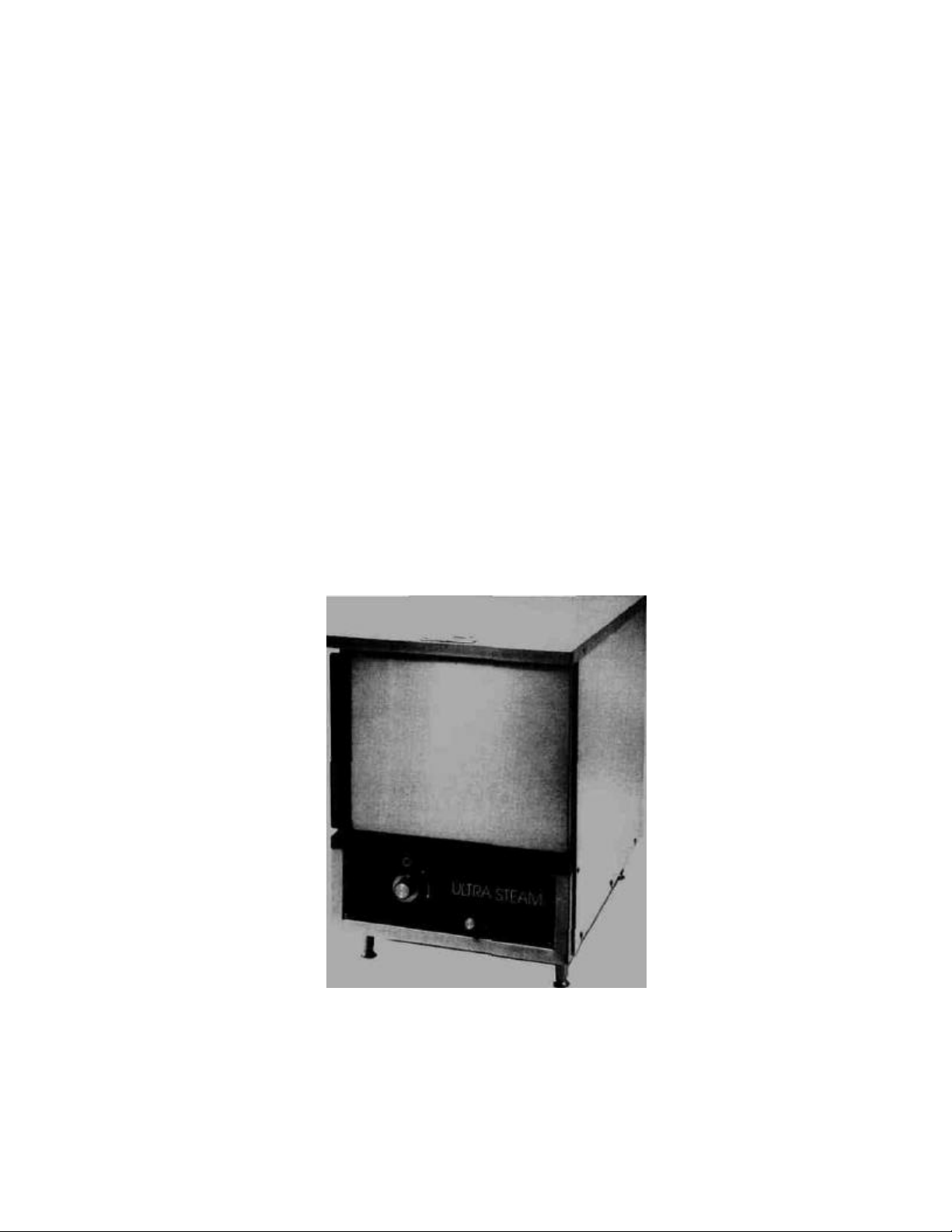
Ultra Steam® Convection Steamer
Models:
3005 CTE
3010 CTE
3015 CTE
Revision No. 1-284
Form Number S-2267A 2/84 Printed in USA
Market Forge Co.
35 Garvey Street Everett, MA02149 Tel. (617) 387-4100,
Telex 94-9414, Cable MAFORCO
Page 2

TABLE OF CONTENTS
Section
SECTION 1 INTRODUCTION
1.1 Description
1.2 Service
SECTION 2 TROUBLE-SHOOTING
2.1 General
2.2 Electrical Fault Isolation
Page
1-1
1-1
2-1
2-1
LIST OF ILLUSTRATIONS
Figure Page
SECTION 2 TROUBLE-SHOOTING
2.1 Schematic & Wiring Diagram, 60Hz. 2-4
2.2 Schematic & Wiring Diagram, 50Hz 2-5
LIST OF TABLES
Tables Page
SECTION 2 TROUBLE-SHOOTING
2.1 Trouble-Shooting Guide 2-1
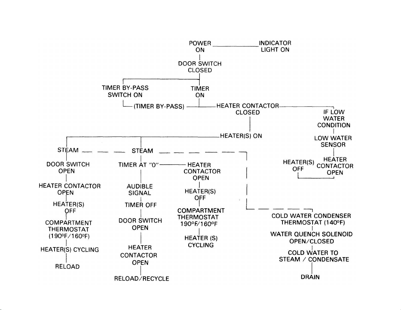
2.2 Ultra Steam® Function 2-3
Section Page
SECTION 3 ILLUSTRATED PARTS LIST
3.1 General 3-1
3.2 Ordering Information 3-1
3.3 Index of Illustrated Parts 3-1
Figure Page
SECTION 3 ILLUSTRATED PARTS LIST
3.1 Base and Steamer Assembly 3-2
3.2 Electrical Assembly 3-4
3.3 Plumbing Assembly 3-6
3.4 Door Assembly 3-10
Tables Page
SECTION 3 ILLUSTRATED PARTS LIST
3.1 Parts List for Base and Steamer Assembly 3-3
3.2 Parts List for Electrical Assembly 3-5
3.3 Parts List for Plumbing Assembly 3-7
3.4 Parts List for Door Assembly 3-11
Page 3

SECTION 1 INTRODUCTION
Ultra Steam® Convection Steamers are electrically powered high-capacity cookers featuring improved energy
efficiency. These units are designed to reduce power consumption by jacketing the cooking compartment with
the steam generator. Because the cooking compartment and steam generator are joined to become a single unit,
the need for steam supply piping has been eliminated.
1.1 Description
The Ultra Steam® Convection Steamer was designed
and built to derive maximum value from energy
supplied. Jacketing of the steam generator around the
sides and bottom of the cooking compartment
produces an efficient cooker. Steam is directed into
the cooking chamber through supply jets.
For ease of maintenance, the steam generator is
accessed from the front through the clean-out port.
This access hole allows service personnel to inspect
interior of generator for evidence of Corrosion, buildup of sediment, or other conditions which may be
detrimental to operation of unit.
1.2 Service
Should repairs be required, a network of authorized
service agencies is available to assist with prompt
service. A current Directory of Authorized Service
Agencies and service assistance may be obtained by
contacting:
Product Service Department
Market Forge Company
35 Garvey Street
Everett, MA 02149
Telephone: (617) 387-4100
The model and serial numbers must be referenced
when corresponding with Market Forge.
1-1
Page 4

SECTION 2 TROUBLE-SHOOTING
PROBLEM
Clean or replace
2.1 General
This section contains trouble-shooting and
maintenance information to assist service personnel in
locating the general source of problems which may
occur with the Ultra Steam® Convection Steamer. It is
recommended that local authorized service be
obtained for assistance in. completing trouble-shooting
procedures.
Table 2-1 serves as a general guide to trouble
shooting. Before attempting to utilize this
information, service personnel should be thoroughly
familiar with the operating instructions and the function
of all controls in Operator's Manual, form number S-
2262.
2.2 Electrical Fault Isolation
Correction of an electrical failure first requires
isolation of the fault to a single circuit or component.
In most cases, the nature of the steamer will be
sufficient to isolate it to one or more circuit elements.
Table 2-2 is provided as a guide for isolating electrical
faults which may occur in operation of the cooker.
Wiring diagram and schematic diagram are provided
for locating the source of the electrical failures.
TROUBLE-SHOOTING GUIDE
This trouble-shooting guide lists some common difficulties which the operator may encounter in using the cooker,
together with possible solutions.
Probable Cause Remedy
SWITCH FAILS TO LIGHT WHEN POWER SWITCH IS PUSHED ON
a. Power to cooker is off
b. Burned out bulb-faulty switch
STEAM GENERATOR FAILS TO PRODUCE STEAM
a. Water supply valve closed
b. Purge/drain valve open
c. Faulty heating element(s)
d. Solenoid valve stuck closed
e. Water level sensor stuck
NO STEAM IN COOKER COMPARTMENT
a. Steam jets restricted
b. Door interlock switch faulty
c. Timer by -pass switch faulty
d. Thermostat faulty
DOOR LEAKS STEAM
a. Door out of adjustment
b. Drain line clogged
Locate external breaker and place it in ON position
Replace switch
Open valve
Close purge/drain valve
Replace heating elements)
a. Clean or replace valve
b. Replace coil
Clean jets with wire or replace
Replace interlock switch
Replace by -pass switch
Replace thermostat make sure proper thermostat
is used 190°F 88° C or 160°F 71°C
Adjust door catch
Clean drain line
Table 2-1 2-1
Page 5

TROUBLE-SHOOTING GUIDE (cont.)
WATER EXITING THROUGH STEAM JETS
a. Generator solenoid valve stuck open a. Clean or replace valve
b. Water level sensor stuck b. Replace coil
GENERATOR FAILS TO PURGE
a. Purge/drain valve clogged a. Clean purge/drain valve
b. Unit operating b. Push ON/OFF switch to OFF position
OPEN DRAIN LINE EMITS STEAM
a. Condenser solenoid valve stuck closed a. Clean or replace valve
b. Condensate thermostat faulty b. Replace coil Replace thermostat
c. Wat er supply to condenser off Open water inlet
TIMER DOES NOT FUNCTION
a. Timer faulty a. Turn timer past 10-minute mark to verify operation
b. Check electrical connections
c. Replace timer
b. Timer by -pass switch faulty a. Place by -pass switch in timer controlled (left) position
b. Replace by -pass switch
Page 6
Page 7

Page 8

Page 9

SECTION 3 ILLUSTRATED PARTS LIST
3.1 General
This section contains a complete listing of all
replaceable parts of the Ultra Steam® Convection
Steamer. For the purpose of parts identification, the
unit is broken down into functional assemblies, and
each assembly is shown in an exploded view which is
keyed to the accompanying parts list. Each parts list
contains the figure index number, the Market Forge
part number, and an abbreviated description.
3.2 Ordering Information
Orders for repair parts should be directed to the
nearest authorized parts distributor. For a current
Market Forge Authorized Parts Distributor List
contact:
Customer Service Department Market
Forge Company 35 Garvey Street
Everett, MA 02149 Telephone: (617)
387-4100
3.3 Index of Illustrated Parts
Figure
or
Table
F3-1 Base and Steamer Assembly
T3-1 Parts List for Base and
Steamer Compartment
F 3-2 Electrical Assembly
T3-2 Parts List for Electric Assembly
F3-3 Plumbing Assembly
T3-3 Parts List For Plumbing Assembly
F3-4 Door Assembly Complete
T3-4 Parts List for Door Assembly
3-1
Page
3-2
3-3
3-4
3-5
3-6
3-7
3-10
3-11
Page 10

Page 11

Parts List for Base Steamer Compartment
Item No. Part No. Description
1 91-7510 Panel, Outer, Left Side
2 91 -7070 Panel, Back
3 91 -7073 Cover, Box, Terminal
4 91 -7505 Panel, Outer, Right Side
5 91-7150 Assy., Top, Outer
6 91 -7501 Rack, Pan
7 91 -7508 Assy., Trough
8 91-7804 Screw, Orifice 5KW
9 91-7515 Screw, Orifice 10& 15KW
10 91-7880 Assembly, Weldment, Strainer & Clip
11 91 -7230 Assy., WIdmt., Base, Bezel & Compt/Boiler
12 91 -7405 Assy., Weldment, Hinge, Door
13 91 -7504 Catch, Door
14 91-7520* Bracket, Mounting, Thermostat
15 10-1764* Screw, Mach., Truss Hd., ST. ST., #10-32 x 1/2" Lg.
16 10-1959* Screw, Mach., Truss Hd., ST. ST., #10-24 x 3/8" Lg.
17 10-0100* Washer, Nylon, .040 Thk., 1/2" OD
18 10-2509* Lockwasher, Med. Series , #10, ST. ST. .062 Wd. x .047 Thk.
19 10-2338* Nut, Hex, ST. ST. #10-24
20 10-1761* Screw, Mach,, Truss Hd., ST. ST. #8-32 x 3/8" Lg.
21 91 -7885 Spacer, Hinge 3/8 OD x 1/2 Lg.
22 10-2413* Washer, Plain, ST. ST. #10
23 10-1956* Screw, Tapping-Truss Hd., #8 x 3/8 Lg.
24 91-7325 Stud, Pan Rack Support
*These parts may be purchased locally Table 3-1
3-3
Page 12

Figure 3-2. Electrical Assembly.
Page 13

Parts List for Electrical Assembly
Item No. Part No. Description
1 91 -7083 Panel, Control
2 10-4485 Knob, Buckeye
3 09-5243 Knob, Skirted with indicator arrow 2" Dia. D-Shaft-Right
4 09-6522 Switch, Push button w/lamp DPDT, reads POWER
5 10-6293 Timer, 60 Minute, 240V, 50/60 Hz
6 10-7903 Switch, Toggle, DPDT, 15 Amp/125VAC, 10 Amp/250VAC, .250 Spade Terminal
7 10-1739* Screw, Mach., Truss Hd., ST. ST., #8-32 x 1/2" Lg.
8 09-3856* Washer, Plain, Nylon, #8, 3/8 OD x 16" Thk.
9
Flange (Part of Heat er Cartridge)
9A 91-7502 Plate, Cover, Blank, Heating Element
10 91-7521 Gasket, Heating Element
11 10-9276 Push Button Boot
12 10-6859 Microswitch
13 09-3424* Screw, Mach., Truss Hd., #10-32 1/4 Lg.
14 09-6484 Contactor, 60 Amp, 3 Pole, 208/240V, 50/60 Hz
14A 10-5476 Contactor, 40 Amp, 3 Pole, 208V, 50/60 Hz
14B 10-5943 Contactor, 40 Amp, 3 Pole, 240V, 50/60Hz
15 91-7128 Bracket, Mounting, Elect. Comp.
16 10-1764* Screw, Mach., Truss Hd., ST. ST., #10-32 x 1/2" Lg.
17 09-6516 Siren, Audio Alert, 120V
18
Knurled Nut (Part of Item 17)
19 10-1739* Screw, Mach., Truss Hd., ST. ST., #8-32 x 1/2" Lg.
20 10-2330* Nut, Hex, ST. ST., #8-32
21 10-2518* Lockwasher, Med. Series, ST. ST., #8, .055 wide, .040 Thk.
22 91-7115 Box, Terminal
23 10-5070 End Piece, Sectional Terminal Block
24 10-5503 Terminal Block
25 10-1959* Screw, Mach., Truss Hd., ST. ST., #10-24 x 3/8" Lg.
26 09-6575 Bushing, Snap, Nylon, 11/16 I.D.
27 10-5492 Ground Lug
28 10-5678 Clip, Cable, Cellulose, 7/16" Dia.
29 10-2509* Lockwasher, Med. Series. ST. ST. #10
30 10-2338* Nut, Hex, #10-24
31 09-6548 Thermostat, Snap Disc, Surface Mounting Type, 190°F 88°C
31A 09-6559 Thermostat, Snap Disc, Surface Mounting Type, for High Altitude 160°F 71°C
32 09-6557 Heater, Cartridge, 2 Wire, 208V (1pH)
32A 09-6553 Heater, Cartridge, 3 Wire, 208V (3pH)
32B 09-6558 Heater, Cartridge, 2 Wire, 240V (1pH)
32C 09-6554 Heater, Cartridge, 3 Wire, 240V (3pH)
32D 09-6556 Heater, Cartridge, 3 Wire, 380V (3pH)
32E 09-6555 Heater, Cartridge, 3 Wire, 415V (3pH)
These parts may be purchased locally Table 3-2
3-5
Page 14

Figure 3-3. Plumbing Assembly
Page 15

Item No. Part No. Description
3A
3B
4
6
7
8
9
10
11
12
13
14
15
16
20
21
22
23
24
25
26
27
28
30
31
32
33
34
35
36
37
Parts List for Plumbing Assembly
1 09-4878 *
2
3
10-2858 *
09-4862
10-8368
10-8369
10-4056 *
5
17
18
19
29
29A
38 91 -7457 Line, Ball Valve to Drain
10-2847 *
10-1120 *
10-2813 *
91-3791
10-2830 *
91-7456
10-3490 *
10-3320 *
09-6549
91-7147
10-2403 *
10-2508 *
10-2336 *
10-2837 *
91-7462
10-2813 *
91-7071
10-3644 *
10-3358 *
10-1055 *
91-7455
91-7072
91-7146
10-3628
10-0865
09-4902
91-7262
10-3357 *
09-4887
91-7451
09-4895 *
91-7216
91-7464
91-7463
Elbow, 90° Reducing, Ml 3/8 x 1/8
Elbow, 90° Comp., Brass, 1/ 4 OD x 1/8 IPS
Nozzle, Jet, Full Cone, 1/4 IPS Pipe Conn., .046 Dia. Orifice (Model
3005 CTE)
Nozzle, Jet, Full Cone, 1/4 IPS Pipe Conn., .062 Dia. Orifice (Model
3010 CTE)
Nozzle, Jet, Full Cone, 1/4 IPS Pipe Conn., .078 Dia. Orifice (Model
3015 CTE)
Bushing, Reducing, Outside Hex, Ml 3/4 IPS x 1/4 IPS
Nipple, Close, Bl, 3/4 IPS
Full Coupling, Steel, 3/4 IPS
Plug, Sq. Hd., Ci, 3/4 IPS (Models 3005 CTE and 3010 CTE only)
Vacuum Breaker, Rework (Model 3015 CTE only)
Elbow, 90° Street, M l, 3/4 IPS
Line, Solenoid -Drain CWC
Tee, Side Outlet, Plain, Ml, 3/4 IPS
"Y" Branch, Ml, 3/4 IPS
Thermostat, Snap Disc, Probe Type
Clamp, Bracket, Cross
Washer, Plain, ST. ST., 1/4
Lockwasher, ST. ST., 1/4
Nut, Hex, ST. ST., 1/4-20
Elbow, 90° Comp., 5/8 OD x 1/2 IPS
Assy. Weldment, Tee, Side Outlet
Plug, Sq. Hd., Brass, 3/4 IPS
Bracket, Mounting, Tee
Plug, Sq. Hd., Brass, 3/8 IPS
Elbow, 90° Comp., 3/8 OD x 3/8 IPS
Tee, Brass, 3/8 IPS
Line, Water, Solenoid to Broiler
Bracket, Support, Tee
Bracket, Outlet, Drain Cross
Adaptor, Comp., Straight, Brass, 1/4 IPS x 3/8 OD
Valve, Solenoid, 240V, 50/60 Hz, 1/4 IPS-N.C.
Valve, Solenoid, 208V, 50/60 Hz, 1/4 IPS-N.C.
Bracket, Mounting, Solenoid
Elbow, 90° Comp., 3/8 OD x 1/4 IPS
Low Water Cutoff
Assembly, Elbow and Line, Broiler to Ball Valve
Valve, Ball, 1/2 IPS
Extension, Knob, Valve, Ball
Channel, Mounting, Drain, Valve, Ball
Clip, Holding, Drain, Valv e, Ball
*These parts may be purchased locally Table 3-3
3-7
Page 16

Table
3-3
(contJ
Parts List for Plumbing Assembly (Cont'd.)
Item No. Part No. Description
39 91 -7521 Gasket, Heating Element
40 91 -7502 Plate, Cover, Blank, Heating Element
41 91-7113 Plate, Cover, Boiler
42 91-7114 Gasket, Water Fill Cover
43 10-8102 Valve, Pressure Relief, 1/2 PSI 3/4 NPT Low Pressure
44 10-2160 * Screw, Mach., Truss Hd., #10-32 x 3/8 Lg.
45 10-2972 * Rivet, Pop, 1/8 Dia. x .232
46 10-1764 * Screw, Mach., Truss Hd., #10-32 x 1/2 Lg.
47 10-1953 * Screw, Mach., Pan Hd., #10-24 x 1/2 Lg.
48 09-3431 * Screw, Mach., Hex Hd., ST. ST., #3/8-16 x 3/4 Lg.
49 10-2507 * Lockwasher, ST. ST., 3/8
50 10-1739 * Screw, Mach.. Truss Hd., ST. ST., #8-32 x 1/2 Lg.
*These parts may be purchased locally
3-8
Page 17

Figure 3-4. Door Assembly (Part No. 91- 7040} 3-10
Page 18

Parts List for Door Assembly
Table
3-4
Item No. Part No. Description
1 91-7046 Door, Outer
2 91 -7045 Door, Inner, Cast Aluminum
3 91-7043 Panel, Door, Inner
4 91-7048 Connector, Door, Inner
5 91-7041 Handle, Door, Acrylic
6 91-7047 Pin, Hinge
7 09-1608 Striker, Casting, Latch, Door
8 91-7049 Spring, Door, Inner
9 09-4213 Gasket, Door, Silicone
10 91-7044+* Insulation, Door, Fiberglass Back, Foil Faced 8-78" x 11-1/16" x 3/8"
11 09-6542 Bearing, Bronze 1/4 ID x 1/2 Long
12 09-6543 Ring, Retaining, Crescent
13 10-2044* Screw, Mach., Hex, ST. ST., #10-24 x 1/2" Lg.
14 10-2526* Washer, Extrenal Tooth, ST. ST., #10
15 10-1768* Screw, Truss Hd., ST. ST., #10-32 x 1" Lg.
16 10-2550* Nut, Acorn, ST. ST., #8-32
17 10-1739* Screw, Truss Hd., ST. ST., #8-32 x 1/2" Lg.
18 10-2518* Lockwasher, ST. ST., #8
19 10-0795* Loctite
20 91-7050+* Insulation. Door, Fiberglass, Front, Foil Faced 11 -1/2 x 12-3/4" x 3/8"
21 10-0100* Washer, Flat, White Nylon
22 10-3522+ Sealant. Adhesive, Clear, #732 RTV
23 09-2610 Bearing, Bronze, 1/4 ID x 3/8 Lg.
*These parts may be purchased locally
+Not shown in exploded view
3-11
 Loading...