

Page 1

OWNER’S MANUAL
A-PLUS STEAM COOKER
Form Number: S-2330 REV: C 07/06
Printed in U.S.A. 35 Garvey Street l Everett l MA l 02149
Tel: (617) 387-4100 l Fax: (617) 387-4456 l Outside MA Fax: (800) 227-2659
E-Mail: CUSTSERV@mi.com l Website: www.mi.com
Page 2

TABLE OF CONTENTS
OPERATING INSTRUCTIONS
The A-Plus Steam Cooker may be used for either:..? ....................................................... 1
Preheating Compartment .................................................................................................. 1
Fig. 1 Door Latches ...........................................................................................................
Convection Steam Cooking ...............................................................................................1
Pressure Cooking ...............................................................................................................
Cleaning ............................................................................................................................2
A-Plus Cooker Facts on Parade .........................................................................................3
Suggested Cooking Times .................................................................................................
TROUBLE-SHOOTING
Description .........................................................................................................................7
Basic Functioning ...............................................................................................................7
Service ................................................................................................................................
General ............................................................................................................................... 7
Electrical Fault Isolation .....................................................................................................7
Fig. 2 Wiring and Schematic Diagram ................................................................................8
General Touble-Shooting Guide .........................................................................................
Electrical Fault Isolation Guide (Upper Compartment) .......................................................
1
2
4
7
9
10
MAINTENANCE
General ..............................................................................................................................11
Preventive Maintenance ....................................................................................................
Drain Screen Cleaning and Removal ................................................................................
Safety Valve Check ............................................................................................................11
Inner Door Cleaning and Removal ....................................................................................11
Door Wheel Lubrication .....................................................................................................12
Steam Condenser Adjustment ...........................................................................................
ASSEMBLY
Door Assembly Instructions ................................................................................................12
ILLUSTRATED PARTS LIST
General ..............................................................................................................................
Ordering Information ..........................................................................................................13
Door Assembly ....................................................................................................................14
Control Panel ......................................................................................................................15
Right Side Control Area ......................................................................................................16
Boiler Base - Side View ......................................................................................................18
Right Rear View ..................................................................................................................18
Front Control Panel .............................................................................................................19
11
11
12
13
Page 3

OPERATING INSTRUCTIONS
The A-PLUS STEAM COOKER may be used for either:
a.) A Steam Pressure Cooker in both compartments (As a Pressure Cooker, it will cook fresh and defrosted foods).
b.) A Convection Steam Cooker in the TOP compartment ONLY (As a Convection Cooker, it will defrost and cook
frozen vegetables or 3/4” thick meat and seafood in a minimal amount of time)
PREHEATING COMPARTMENT:
Before each initial operation of the cooker and at other times
when the cooking compartment is cold, a 5-minute
preheating cycle is required.
1. Check steam supply to insure pressure. a.) Direct
Steam - Turn on valve of external steam supply.
b.) All other Units - Follow steam generator operating
instructions inside cabinet base.
2. Close cooking compartment door to
engage both door latches. If door doesn’t
latch, turn door wheel counterclockwise
until both latches are engaged (see Fig. 1).
3. Seal cooking compartment by turning
door wheel clockwise until wheel is hand tight.
Fig. 1. Door Latches
CAUTION: DON’T WRENCH DOOR WHEEL TIGHT! Damage to door wheel and door gasket may result.
4. Ensure that automatic override switch is in AUTO (Down) position.
5. Set controls for cooking compartment to be preheated:
a.) Top Compartment:
1. Place mode selector switch in the PRESSURE Cooking (Up) position.
2. Set 60-Minute Timer (Top) to 5-Minute position. (Go beyond 15-Minutes and back to 5-
Minutes for accurate timing.)
3. Pull steam control lever out and down. (
unit is operating. If pressure drops below 3 PSI (
see Fig. 1) Indicator light will come on to show that the
0.2 kg/cm2), adjust timer settings.
b.) Bottom Compartment:
1. Set 60-Minute timer to 5-Minute position.
2. Pull steam control lever out and down. (
see Fig. 1) Indicator light will come on to show that the
unit is operating. If pressure drops below 3 PSI (0.2 kg/cm2), adjust timer settings.
6. At end of cooking cycle, steam control lever is released automatically, exhausting steam and condensation
from the compartment, and causing the buzzer to sound. Turn off buzzer by setting timer to OFF position.
7. Allow pressure to return to 0 PSI. Loosen door by turning wheel counterclockwise. Push primary door latch
from door lip. Allow remaining steam to dissipate from the partially open door. Then, after determining that
no water is owing out under the bottom of the door, lift the secondary door latch and open door fully.
NOTE: If automatic controls fail, place automatic override switch to MANUAL (Up) position and time manually.
CONVECTlON STEAM COOKING (Top Compartment Only):
Before loading the cooker, be sure compartment is hot If not hot, follow preheating instructions.
Slide pans of frozen food onto pan supports in top cooking compartment.
1.
1
Page 4

OPERATING INSTRUCTIONS
Close cooking compartment door to engage both door latches If door does not latch, turn door wheel coun-
2.
terclockwise until both latches are engaged. (see Fig. 1)
Place cooking mode selector switch in PRESSURELESS COOKING (Down) position.
3.
Set 15-minute timer (Center) to required cooking time.
4.
5. Turn off buzzer which sounds to indicate cycle complete by setting timer dial to the OFF position.
6. Loosen door by turning wheel counterclockwise. Push primary door latch from door lip. Allow remaining
steam to dissipate from partially open door Then, after determining that no water is owing under bottom of
the door, lift the secondary door latch up and open the door fully.
7. Unload by sliding pans of food from pan supports.
PRESSURE COOKING (Both Compartments):
Before loading the cooker be sure compartment is hot If not hot, follow preheating instructions.
1. Slide pans of food into either cooking compartment
2. Close cooking compartment door to engage both door latches If door does not latch, turn door wheel counterclockwise until both latches are engaged. (see Fig. 1)
3. Ensure that automatic switch is in AUTO (Down) position.
4. Set controls for cooking compartment to be used
a.) Top Compartment:
1. Place mode selector switch in the PRESSURE COOKING (Up) position.
2. Set 60-minute timer (Top) to required cooking time.
3. Pull steam control lever out and down.
b.) Bottom Compartment:
1. Set 60-minute timer to required cooking time.
2. Pull steam control lever out and down.
5. At end of cooking cycle, steam control lever is released automatically exhausting steam and condensate
from the compartment by causing the buzzer to sound. Turn off buzzer by setting timer to the OFF position.
6. Allow pressure to return to 0 PSI. Loosen door by turning door wheel counterclockwise. Push primary door
latch from door lip. Allow remaining steam to dissipate from the partially open door. Then, after determining
that no water is owing out under the bottom of the door, lift the secondary door latch and open the door
fully.
7. Unload by sliding pans of food from pan supports or shelves.
NOTE: If automatic controls fail, place automatic override switch in MANUAL (Up) position and time manually.
CLEANING:
Consult steam generator instructions inside base for shut-down procedure. After each daily operating period,
the A-PLUS should be thoroughly cleaned with mild detergent, making sure compartment is left dry and door is
open.
2
Page 5

OPERATING INSTRUCTIONS
A-PLUS COOKER FACTS ON PARADE
Frozen vegetables should be cooked 6 pans 12” x 20” x 2 1/2” in the PRESSURELESS COOKING MODE
1.
(perforated pans recommended).
Frozen entrees 6 pans 12” x 20” x 2 1/2” should be defrosted and heated in the PRESSURE COOKING
2.
MODE (perforated pans recommended).
Fresh foods 6 pans 12” x 20” x 2 1/2” should be cooked in the PRESSURE COOKING MODE.
3.
Pressureless Cooking should only be used for frozen vegetables or short term defrosting.
4.
All foods, except cakes and pastry, can be cooked in a steam cooking unit.
5.
Steam cooked meals have greater nutritional value since they retain most of their vitamins and minerals.
6.
Because foods are cooked faster by the higher temperature of steam cooking, they can be prepared closer
7.
to serving time, insuring maximum freshness.
Steam cooked food has a higher percent yield -more portions per dollar spent.
8.
Food may be served from the same pan in which it is steam cooked, thus reducing food breakage since
9.
there is no extra handling or transferring of food from cooking pans to serving pans. It also reduces pot
washing tasks.
Some important advantages of steam cooking are: labor saving, reduced operating costs, space saving,
10.
and the lifting of heavy stock pots is eliminated.
Rice and spaghetti products, if thoroughly wet at the start of the cooking process, are very easily prepared.
11.
Foods such as potatoes, poultry, seafood and some meats may be blanched in the steam cooker, thus
12.
reducing the total cooking time and grease absorption.
Fuel is used only when the steam cooking is in operation.
13.
The steam cooker will loosen foods burned on pans making washing easier.
14.
Solid pans are recommended when liquid is to be retained and perforated pans when liquid is not to be
15.
retained.
Eggs may be cooked out of the shell if they are to be chopped, which eliminates peeling after steaming.
16.
The steam cooker can be opened during the cooking period (by rst releasing the steam pressure) to add
17.
or remove items. If any time is lost, an adjustment may be made on the timer.
Steam cooking information, including recommended pan size and type, weight per pan, cooking times, and
18.
pan yields are given on the following pages of this manual.
3
Page 6
OPERATING INSTRUCTIONS
VEGETABLES
RECOMMENDED
APPROX.
FROZEN WT.
ITEM
Snap or Waxed Green Beans 6 # (2.7kg) 2 1/2’ (65mm)
Beets 2” 7 1/2 # (3.4kg) 2 1/2’ (65mm)
Broccoli Stalks 1/2 - 3/4” 6 # (2.72kg) 2 1/2’ (65mm)
Sliced Carrots 9 # (4kg) 2 1/2’ (65mm)
Cauliower Trimmed 1 1/2-2” 6 # (2.72kg) 2 1/2’ (65mm)
Corn on the Cob, Husked 1 doz. 2 1/2’ (65mm)
Cabbage, Head Cored 5 # (2.25kg) 2 1/2’ (65mm)
Onions, 2” 6 # (2.72kg) 2 1/2’ (65mm)
Peas, Shelled 5 # (2.3kg) 2 1/2’ (65mm)
Potatoes, French Fry Cut 10 # (4.5kg) 2 1/2’ (65mm)
Potatoes, Regular Cut 10 # (4.5kg) 2 1/2’ (65mm)
Squash, Clean Cut 3 # (1.4kg) 2 1/2’ (65mm)
Squash, Winter Peeled 9 # (4kg) 2 1/2’ (65mm)
Squash - Summer, Sliced 1” 7 # (3.2kg) 2 1/2’ (65mm)
Turnip, Diced 5 # (2.3kg) 2 1/2’ (65mm)
Canned Vegetables 7 # (3.4kg) 2 1/2’ (65mm)
PER PAN
12” x 20”
PERFORATED
PAN
NUMBER OF
PANS
1-3
4-6
1-3
4-6
1-3
4-4
1-3
4-6
1-3
4-6
1-3
4-6
1-3
4-6
1-3
4-6
1-3
4-6
1-3
4-6
1-3
4-6
1-2
3-4
1-3
4-6
1-3
4-6
1-3
4-6
1-3
4-6
PRESSURELESS
TIMER
SETTINGS
MINUTES
15-20
20-25 25-30 3oz. (85g)
40-45
45-60 30-35 3oz. (85g)
10-15
15-20 25-30 3oz. (85g)
18-21
21-25 35-40 3oz. (85g)
10-15
15-20 30-35 3oz. (85g)
10-12
12-15 12
14-16
16-20 15-20 4oz.(115g)
10-18
15-30 25-30 4oz.(115g)
5-6
7-8 25-30 34oz.(85g)
15-18
18-20 50-3oz. (85g)
20-25
25-30 50-3oz. (85g)
3-5
4-6 3 3/4oz. (105g)
15-20
20-25 25-30 3oz. (85g)
8-12
12-15 30-35 3oz. (85g)
25-30
30-35 20-25 4oz.(115g)
4-5
5-8 25-30 34oz. (85g)
APPROX. NO.
COOKED
SERVINGS
PER PAN
MISCELLANEOUS
Eggs, in Shell 3 doz. 2 1/2’’ (65mm)
Eggs, Out of Shell 4 doz. 2 1/2’’ (65mm)
Rice, Bulletin 16 4 # (1.8kg) 4” (100mm)
Spaghetti, Bulletin 13 3 # (1.4kg) 4” (100mm)
4
1-3
4-6
1-3
4-6
1-2
3-4
1-2
3-4
8-9
9-10
6-7
7-8
22-24
25-27 60-65 3oz. (85g)
20-22
23-26 40-45 4oz. (115g)
36
1 egg each
48
1 egg each
Page 7

FROZEN VEGETABLES
OPERATING INSTRUCTIONS
RECOMMENDED
APPROX.
FROZEN
ITEM
Asparagus Spears 7 1/2 # (3.4kg) 2 1/2’ (65mm) 1-6 8-13 30-3oz. (85g)
Green Beans Regular 6 # (2.7kg) 2 1/2’ (65mm) 1-6 8-13 25-3oz. (85g)
French Cut Green Beans 6 # (2.7kg) 2 1/2’ (65mm) 1-6 4-10 25-3oz. (85g)
Lima Beans 7 1/2 # (3.4kg) 2 1/2’ (65mm) 1-6 12-15 30-3oz. (85g)
Broccoli 6 # (2.7kg) 2 1/2’ (65mm) 1-6 7-10 25-3oz. (85g)
Brussels Sprouts 7 1/2 # (3.4kg) 2 1/2’ (65mm) 1-6 9-14 30-3oz. (85g)
Carrots 6 # (2.7kg) 2 1/2’ (65mm) 1-6 7-12 25-3oz. (85g)
Cauliower 6 # (2.7kg) 2 1/2’ (65mm) 1-6 7-12 25-3oz. (85g)
Cut Corn 7 1/2 # (3.4kg) 2 1/2’ (65mm) 1-6 5-10 30-3oz. (85g)
Mixed Vegetables 7 1/2 # (3.4kg) 2 1/2’ (65mm) 1-6 5-10 30-3oz. (85g)
Peas 7 1/2 # (3.4kg) 2 1/2’ (65mm) 1-6 5-10 30-3oz. (85g)
Spinach 9 # (4kg) 2 1/2’ (65mm) 1-6 Must be Defrosted 30-4oz. (85g)
Squash 7 1/2 # (3.4kg) 2 1/2’ (65mm) 1-6 Must be Defrosted 50-3oz. (85g)
FROZEN PREPARED ENTREES
Lobster Tails
Lobster Tails 6-8 Oz. (170-
225g)
Shrimp C.D.P. 16-20 # (7 1/2-
Green Shrimp 16-20 # (7 1/2-
Bulk Pack, Frozen 3 1/2-4 # (1.6-
Bulk Pack, Defrosted 3 1/2-4 # (1.6-
* Perforated Pan
** Pressure Timer Setting
WT. PER PAN
7-8# (3.2-3.6kg) 2 1/2” (65mm) 1-6 15-20 15-6oz. (170g)
9kg)
9kg)
1.8kg)
1.8kg)
12” x 20”
PERFORATED
PAN
2 1/2” (65mm) 1-6 8-11 75-3oz. (85g)
2 1/2” (65mm) 1-6 11-15 50-3oz. (85g)
2 1/2” (65mm)* 1-6 30-45** 10-6oz. (170g)
2 1/2” (65mm)* 1-6 25-35** 10-6oz. (170g)
NUMBER
OF PANS
PRESSURELESS
TIMER
SETTINGS
MINUTES
APPROX. NO.
COOKED
SERVINGS
PER PAN
5
Page 8

OPERATING INSTRUCTIONS
MEAT
1-3
Chicken, Cut-Up 6 # (2.7kg) 2 1/2’ (65mm)
4# Whole 3 Each 4” (100mm)
Fowl, 5# or More Whole 2 Each 4” (100mm)
Fish Fillets 3 # (1.4kg) 2 1/2’’ (65mm)
Frankforts 5 # (2.3kg) 2 1/2’’ (65mm)
Hamburgers 3 oz. (85g) 5 # (2.3kg) 2 1/2’’ (65mm)
Meatballs * 1 oz. (30g) 6 # (2.7kg) 2 1/2’’ (65mm)
Meatloaf* 15 # (6.8kg) 2 1/2’’ (65mm)
Pork Chops Loin Bone 4 oz.
(115g) 6 # (2.7kg) 2 1/2’’ (65mm)
Sausage 1 1/2 oz. (45g) 6 # (2.7kg) 2 1/2’’ (65mm)
Turkey Carcass 20-22 # (9-10kg) 2 1/2’’ (65mm) 1-2 100-120
10-12 # (4.5-
Turkey off Carcass
5kg) 2 1/2’’ (65mm)
4-6
1-2
3-4
1-2
3-4
1-3
4-6
1-3
4-6
1-3
4-6
1-3
4-6
1-3
4-6
1-3
4-6
1-3
4-6
1-3
4-6
18-25
25-30
45-55
55-65
50-60
65-75
8-12
10-15 12-15 2oz. (55g)
3-4
4-5 35-40 2oz. (55g)
12-14
15-18 20-25 2oz. (55g)
18-22
22-25
35-40
40-45
25-30
30-35
18-21
22-25 18-20 2oz. (55g)
50-60
60-75
Protein
15-20 2oz. (55g)
Protein
25-30 2oz. (55g)
Protein
20-25 2oz. (55g)
Protein
20-25 2oz. (55g)
Protein
50-60 2oz. (55g)
Protein
24 2oz. (55g)
Protein
50-60 2oz. (55g)
Protein
55-65 2oz. (55g)
* Raw weight for Meatballs and Meatloaf including Hamburgers and extenders and yields 2 oz. (56g) protein plus extenders or 3 oz. (85g) total portion.
6
Page 9

TROUBLE-SHOOTING
This service and parts section contains descriptive information. Trouble-shooting procedures, maintenance
information, and parts identication for the A-PLUS Cooker. Only information for those electrical and plumbing
systems which are not included in the A Cooker, but are required for the A-PLUS are included.
DESCRIPTION:
The model A-PLUS is a factory modied model A Cooker equipped for operator selection of either pressure or
free-vented pressureless steam cooking in the upper compartment. Double stacked, independently controlled
compartments are tted with single automatic controls. A separate steam source required for operation is factory mounted under the cooker with all steam, drain and electric interconnections completed (Models A-PLUS
E, A-PLUS G and A-PLUS SC). The cooker can also be supplied on a cabinet containing plumbing controls for
direct connection to an existing steam source (Model A-PLUS D).
BASIC FUNCTIONING:
The upper compartment of the A-PLUS may be converted from a pressure steam cooker to a pressureless,
free-vented steam cooker simply by placing a mode selector switch in the required position followed by setting
a timer:
For pressure cooking, the compartment is automatically sealed by the closing of an exhaust valve and
1.
evacuation of air through a steam trap as steam is injected. The compartment remains at approximately 5
Ibs. steam pressure until the operator-selected cooking duration ends (top timer).
For pressureless cooking, the compartment remains vented to the drain system while steam is injected. In
2.
this manner a continuous ow of steam circulates throughout the compartment and out the exhaust for the
cooking duration (center timer).
The lower compartment functions at all times as described in 1 above and utilizes an independent timer (bottom timer).
SERVICE:
Should repairs be required, a network of authorized service agencies is available to assist with prompt service.
A current Directory of Authorized Service Agencies and service assistance may be obtained by contacting:
Product Service Department
Market Forge, 35 Garvey Street, Everett, Massachusetts 02149-4403, Telephone: (617) 387-4100
The model and serial numbers must be referenced when corresponding with Market Forge.
GENERAL:
This Section contains trouble-shooting guide information to assist service personnel in locating the general
source of problems which may occur with the A-PLUS COOKER. It is recommended that local authorized service be obtained for assistance in completing the trouble-shooting procedures.
The table on page 9 serves as a general guide to trouble-shooting. Before attempting to utilize this information,
service personnel should be thoroughly familiar with the operating instructions and the function of all controls in
the operating instructions.
ELECTRICAL FAULT ISOLATION:
Correction of an electrical failure rst requires isolation of the fault to a single circuit or components. In most
cases the nature of the gure and its effect upon the operation of the cooker will be sufcient to isolate it to one
or more circuit elements. The electrical fault isolated guide is provided on page 10 for isolating electrical faults
which may occur in operation of the upper compartment. Wiring Diagram, and schematic diagram (see Fig. 2) are
also provided for locating the source of electrical failures.
7
Page 10

TROUBLE-SHOOTING
Fig. 2. Wiring and Schematic Diagram
8
Page 11

TROUBLE-SHOOTING
GENERAL TROUBLE-SHOOTING GUIDE
PROBLEM
PROBABLE CAUSE REMEDY
1. INDICATOR LIGHT FAILS TO LIGHT IN PRESSURE COOKING MODE.*
a. Power to A-Plus Cooker off. a. Locate external circuit breaker for incoming power and place in
ON position.
b. Selector Switch in Pressureless Cooking position. b. Place in Pressure Cooking Position.
c. 60-Minute Timer not set. c. Set 60-Minute Timer.
2. INDICATOR LIGHT FAILS TO LIGHT IN PRESSURELESS COOKING MODE.*
a. Power to A-Plus Cooker off. a. Locate external circuit breaker for incoming power and place in
ON position.
b. Selector Switch in Pressure Cooking Position. b. Place in Pressureless Cooking Position.
c. 15-Minute Timer not set. c. Set 15-Minute Timer.
3. INDICATOR LIGHT FAILS TO LIGHT WITH SELECTOR SWITCH IN PRESSURE COOKING POSITION AND 60-MINUTE
TIMER SET.*
a. Power to A-Plus Cooker off. a. Locate external circuit breaker for incoming power and place in
ON position.
b. Indicator Light burned out. b. Replace light.
c. Faulty wiring. c. Inspect condition of wire, and tightness of all connections.
Correct as needed.
d. Faulty Selector Switch. d. Replace Switch.
e. 60-Minute Timer Contact Faulty. e. Replace Timer.
f. Faulty Microswich. f. Replace Switch.
4. INDICATOR LIGHT FAILS TO LIGHT WITH SELECTOR SWITCH IN PRESSURELESS COOKING POSITION AND 15-MINUTE
TIMER SET.*
a. Power to A-Plus Cooker off. a. Locate external circuit breaker for incoming power and place in
ON position.
b. Indicator Light burned out. b. Replace light.
c. Faulty wiring. c. Inspect condition of wire, and tightness of all connections.
Correct as needed.
d. Faulty Selector Switch. d. Replace Switch.
e. 15-Minute Timer Contact Faulty. e. Replace Timer.
5. PRESSURE COOKING MODE FAILS TO STOP.
a. Defective 60-Minute Timer Motor or Contact. a. Replace Timer.
b. Defective Steam Exhaust Valve. b. Replace Valve.
6. PRESSURELESS COOKING MODE FAILS TO STOP.*
a. Defective 15-Minute Timer Motor or Contact. a. Replace Timer.
b. Defective Steam Inlet Solenoid Valve. b. Replace Valve.
7. STEAM FAILS T ENTER COMPARTMENT IN PRESSURELESS COOKING MODE (WITH INDICATOR LIGHT ON).*
a. Compartment door not closed. a. Securely latch door closed.
b. No steam entering steam line. b. Check steam generator and pressure producing valve for
proper operation.
c. Faulty or jammed door interlock switch. c. Adjust or replace switch.
d. Faulty steam inlet solenoid valve. d. Replace valve.
NOTE: * Pertains to upper compartment only.
8. BANGING SOUND OR STEAM ENTERING BOTTOM COMPARTMENT WITH TOP COMPARTMENT IN PRESSURELESS
COOKING MODE.
a. Improperly adjusted cold water ow control valve. a. Adjust valve. Increase ow of steam, decrease for banging.
NOTE: * Pertains to upper compartment only.
9
Page 12
TROUBLE-SHOOTING
GENERAL TROUBLE-SHOOTING GUIDE
PROBLEM
PROBABLE CAUSE REMEDY
9. STEAM ENTERS COMPARTMENT AT ALL TIMES.
a. Faulty inlet solenoid steam valve a. Replace valve.
b. Defective or jammed door interlock switch. b. Clean or replace switch.
c. Defective manual steam valve. c. Check valve and mechanism.
10. NO STEAM PRESSURE GAUGE READING COOKING MODE.
a. Insufcient steam input from steam generator. a. Check generator for 15PSI output. Adjust
b. Faulty pressure gauge. b. Replace gauge
c. Faulty steam exhaust valve. c. Check vavle and mechanism.
d. Faulty relief valve. d. Replace valve.
11. BUZZER FAILS TO SOUND AT END OF PRESSURE COOKING DURATION.
a. Faulty microswitch. a. Replace microswitch.
b. Faulty buzzer. b. Replace buzzer.
12. BUZZER FAILS TO SOUND AT END OF PRESSURELESS COOKING DURATION (WITH INDICATOR LIGHT OFF).*
a. Faulty 15-Minute timer. a. Replace 15-Minute timer.
b. Faulty buzzer. b. Replace buzzer.
13. COOKING COMPARTMENT FAILS TO REACH COOKING TEMPERATURE IN PRESSURE COOKING MODE.
a. Air in cooking compartment. a. Replace steam trap.
b. Low steam pressure. b. See item 7.
14. IN PRESSURE COOKING MODE PULLING UP ON SAFETY VALVE KNOB FAILS TO CAUSE PRESSURE DROP.
a. Defective relief valve. a. Replace relief valve.
15. IN PRESSURE COOKING MODE TOP COMPARTMENT ACCUMULATES WATER.
a. Plugged drain screen. a. Clean.
NOTE: * Pertains to upper compartment only.
ELECTRICAL FAULT ISOLATION GUIDE - UPPER COMPARTMENT
FAILURE LOCATION
1. WILL NOT OPERATE IN EITHER PRESSURE A. INCOMING POWER.
OR PRESSURELESS COOKING MODE. B. SELECTOR SWITCH.
C. WIRING.
2. OPERATES IN PRESSURE MODE BUT NOT IN A. SELECTOR SWITCH.
PRESSURELESS MODE. B. WIRING.
C. 12-MINUTE TIMER.
D. STEAM SOLENOID VALVE.
3. OPERATES IN PRESSURELESS MODE BUT NOT A. SELECTOR SWITCH.
IN PRESSURE MODE. B. WIRING.
C. 60-MINUTE TIMER.
4. INDICATOR LIGHT OFF IN EITHER MODE. A. INDICATOR LIGHT.
B. WIRING.
5. INLET SOLENOID VALVE FAILS TO OPEN BUT A. DOOR INTERLOCK SWITCH.
INDICATOR LIGHT IS ON IN PRESSURELESS B. INLET SOLENOID VALVE COIL.
MODE. C. WIRING.
6. BUZZER FAILS TO SOUND AT END OF EITHER A. 15-MINUTE TIMER.
PRESSURE OR PRESSURELESS COOKING B. BUZZER.
MODE. C. WIRING.
7. WILL NOT STOP OPERATING IN PRESSURE MODE. A. 60-MINUTE TIMER MOTOR.
8. WILL NOT STOP OPERATING IN PRESSURELESS MODE. A. 15-MINUTE TIMER MOTOR.
Page 13
MAINTENANCE
GENERAL:
This section contains both preventive and corrective
maintenance information required for the A-PLUS
Cooker.
Preventive maintenance may be performed by maintenance personnel at the establishment in which the
cooker is installed. It is recommended that user personnel never attempt to make repairs or replacements
to the equipment without the assistance of authorized
service. Assistance in service methods or a current
FREQUENCY PROCEDURE
DAILY 1. CLEANING: Remove pan supports, shelves and shelf supports, and thoroughly wash and
rinse interior of both cooking compartments. Be sure the drain screen, located inside top
compartment, is clear of all food particles.
WEEKLY 1. SAFETY VALVE CHECK: With upper compartment in operation in the pressure cooking
mode, lift up on level of forward mounted safety valve. Repeat for rear mounted safety valve.
Steam should ow freely from outlet port, verifying proper functioning and clearing of accumulated deposits in valves.
2. INNER DOOR CLEANING: Remove inner door from both compartments. Wash inner
door and inside of outer door with mild detergent, rinse and reassemble.
MONTHLY 1. DOOR WHEEL LUBRICATION: Check door hand wheel rotation for ease of motion. If
wheel resists rotation when door is unlatched, lubrication is required. Remove inner door and
apply graphite lubrication to screw threads.
Directory of Authorized Service Agencies may be obtained from Market Forge.
PREVENTIVE MAINTENANCE:
A good preventive maintenance program begins with
the daily cleaning procedure described in the table below. Additional preventive maintenance operations are
presented in this section .
DRAIN SCREEN CLEANING & REMOVAL:
The drain screen inside the top compartment is provided to prevent blockage of the drain line. It must be kept
clean at all times by scrubbing daily with a stiff bristle brush.
WARNING: A plugged drain may cause compartment ooding, resulting in overow of scalding water
when door is opened.
Should the drain screen require removal due to excessive blockage or damage, the truss head screw is loosened and the screen slipped out. The screen must be in position, completely covering the lower drain opening,
prior to reuse of the A-PLUS.
SAFETY VALVE CHECK:
The safety valves are protective devices which automatically relieve excessive pressure (above 8 PSI) in the
unlikely event of equipment malfunction. Manual opening of the valves is also possible and should be done
once a week to assure valves are clear and mechanically sound.
Place upper cooker compartment into operation in the pressure mode and allow pressure to build to about
1.
4 PSI.
Pull up on safety valve lever for forward-mounted valve (closest to manifold box on left side of cooker).
2.
Flow of steam from the valve outlet veries correct manual valve function and clears exhaust passage.
NOTE: Steam is not present at relief valve until steam trap has evacuated all air from the cooker compartment. Presence of adequate steam should be checked (4-5 psi on gauge) before checking valve.
Repeat step 2 for rear-mounted valve.
3.
INNER DOOR REMOVAL & CLEANING:
The door assembly includes an outer door with mounted hand wheel and an inner door with sealing gasket.
The inner door parts should be cleaned weekly to ensure proper sealing against compartment opening.
11
Page 14

MAINTENANCE
S-4021
07/04
35 Garvey StreetEverettMA02149Tel: (617) 387-4100Fax: (617) 387-4456Fax outside MA: (800) 227-2659
E-Mail: custserv@mfii.com Website: mfii.com
Employee Owned Company
Figure 1.
Figure 2.
Figure 3.
STEP 3:
Line up the outer door pins (marked "A")
with the inner door holes (marked "B").
Set the door in place and turn handle
counter-clockwise until you bring the inner
door to the outer door. (
See Figure 3.
)
STEP 2:
Take the inner door (
Shipped as shown in
Figure 2.
) out of cavity. Remove packaging
and discard.
STEP 1:
Make sure the handle on the door is
turned as far clockwise as possible.
(
See Figure 1.
)
DOOR ASSEMBLY INSTRUCTIONS
FOR A SERIES COOKERS
With door opened and hand wheel turned to full clockwise position, grasp tabs and lift inner door up and
1.
away from door.
Wash inner doors, gaskets and inside of outer door with mild detergent, rinse and reassemble.
2.
DOOR WHEEL LUBRICATION:
The door wheel includes the externally mounted wheel and built-in screw mechanism. Rotation of the door
wheel should be checked monthly for ease of motion. If the wheel grinds or is difcult to turn, the screw should
be lubricated with graphite followed by rotation of the wheel to transfer lubricant into threads in door.
STEAM CONDENSER ADJUSTMENT:
The drain and exhaust plumbing assembly for the A-PLUS Cooker is located inside the cabinet base under
the cooking compartments. In addition to the cold water steam condensing system included with the boiler (or
direct steam connection plumbing), an additional steam condensing circuit is supplied in boilers used with the
A-PLUS Cooker. This circuit functions automatically at all times when the cooker is operating in the Pressureless mode.
ASSEMBLY
DOOR ASSEMBLY INSTRUCTIONS
12
Page 15

ILLUSTRATED PARTS LIST
GENERAL:
This section contains a listing of all replaceable parts of the A-PLUS Cooker, specically required for the
A-PLUS. The parts are identied in illustrations and keyed to an accompanying parts list. Modication parts
required for use with the steam generator or steam direct connection plumbing are also listed. Parts list contain
the gure index number, the Market Forge part number and an abbreviated description.
ORDERING INFORMATION:
Orders for repair parts should be directed to the nearest authorized parts distributor. Contact the factory for a
current Market Forge Authorized Parts Distributor List.
All orders should contain the Market Forge part number(s), the part description(s), the model and serial num-
bers.
13
Page 16

ILLUSTRATED PARTS LIST
Fig. 3. Door Assembly
PART
ITEM
1 90-8310 HAND GRIP 13 10-1981 PIVOT HINGE
2 10-6764 GASKET SCREWS 14 90-8328 HANDWHEEL, SPOKED
3 90-8311 GASKET PLATE 15 91-5148 OUTER DOOR, POLISHED
4 10-0433 DOOR GASKET 16 10-2423 THRUST WASHER
5 91-3152 INNER DOOR 17 10-3080 DOOR BUSHING
6 10-2135 5/16 - 10 x 3/4 HX. HD. BOLT 19 90-8119 STRONG BACK
7 10-2426 11/32 ID x 3/4 OD FT. WASHER ST/ST 20 10-2012 CAP SCREW
8 10-1909 5/16 THREADSEAL 21 10-1973 SUPPORT STUD ASSEMBLY
9 90-8114 DOOR SPRING RELEASE 22 10-2302 HX. NUT 3/8 - 16
10 10-3079 DOOR PIVOT BEARING 23 90-8317 HANDWHEEL BUSHING
11 10-2427 1/16 THK. x 1” OD FLAT WASHER 24 10-2013 HX. JAM NUT 3/8 - 16
12 90-8111 HINGE - POLISHED 10-9998 DOOR ADJUSTING TOOL
NO. DESCRIPTION ITEM
90-8147 INNER DOOR ASSEMBLY (ITEM’S 1-5) 18 10-1696 ROLL PIN
90-8316 HINGE - PAINTED
PART
NO. DESCRIPTION
14
Page 17

ILLUSTRATED PARTS LIST
PART
ITEM
1 91-6327
2 10-6291
3 09-5259
4 10-7903
5 10-5940
6 10-7927
7 10-4748
8 91-5163
9 90-8338
10 10-6859
11 91-3308
12 10-5499
NO. DESCRIPTION QTY.
Fig 3. Control Panel
PANEL, CONTROL, A-PLUS
TIMER, 60 MINUTE, 120V
KNOB, TIMER
SWITCH, TOGGLE
LIGHT, PILOT, WHITE LENS, 120V
TIMER, 15 MINUTE, 120V
GAUGE, PRESSURE
ASS’Y, LATCH, SECONDARY
ASS’Y, HANDLE, LATCH
SWITCH, MICRO
ASS’Y, STRAINER
LIGHT, PILOT, RED LENS, 120V
1
1
(PER COMPARTMENT)
1(PER TIMER)
2
1
1
1
1
(PER COMPARTMENT)
1
(PER COMPARTMENT)
1
(PER COMPARTMENT)
1
1
(PER COMPARTMENT)
Fig. 4 Control Panel
15
Page 18

ILLUSTRATED PARTS LIST
1
11
2
3
4
5
19
6
7
9
10
18
17
16
15
20
14
8
12 13
Fig 4. Right Side Control Area
ITEM PART NO. DESCRIPTION QTY.
1 10-7395 BUZZER 1 (PER TIMER)
2 10-5613 MICRO, SWITCH 1 (PER COMPARTMENT)
3 10-2755 SPRING, VALVE OPERATING ARM 1 (PER COMPARTMENT)
4 90-9215 HANDLE, CONTROL 1 (PER COMPARTMENT)
5 90-8534 ARM, PIVOT 1 (PER COMPARTMENT)
6 90-2434 COMBO. STEAM AND EXHAUST VALVE 1 (PER COMPARTMENT)
7 91-6204 GASKET, VALVE BODY 1 (PER COMPARTMENT)
8 10-2756 SPRING, SYNCHRONIZER 1 (PER COMPARTMENT)
9 90-8537 ARM, ACTUATING VALVE 1 (PER COMPARTMENT)
10 90-4153 SYNCHRONIZER 1 (PER COMPARTMENT)
11 10-1133 O-RING 1 (PER COMPARTMENT)
12 10-9174 RELAY, POWER, MIDGET 1 (PER COMPARTMENT)
13 10-9175 SOCKET, RELAY 1 (PER COMPARTMENT)
14 10-7927 TIMER, 15 MINUTE 1 (PER UNIT)
15 10-5997 SOLENOID 1 (PER COMPARTMENT)
16 90-8905 PUSH ROD 1 (PER COMPARTMENT)
17 08-3415 EYE BOLT WITH NUT 1 (PER COMPARTMENT)
18 10-6291 TIMER, 60 MINUTE 1 (PER COMPARTMENT)
19 10-1967 BOLT, SHOULDER - LINKAGE 1 (PER COMPARTMENT)
20 10-2328 NUT, STOP, 1/4-20, STAINLESS STEEL 1 (PER COMPARTMENT)
16
Page 19

ILLUSTRATED PARTS LIST
1
2
3
4
5
Fig 5. Right Side Control Area
PART
ITEM
1 08-4913 HOSE, ST/ST, BRAIDED 1-2 (PER COMP.)
2 08-3415 EYE BOLT WITH NUT 1 (PER COMPARTMENT)
3 90-8905 PUSH ROD 1 (PER COMPARTMENT)
4 10-5997 SOLENOID 1 (PER COMPARTMENT)
5 10-1033 PRESSURE REDUCING VALVE 1 (PER COMPARTMENT)
NO. DESCRIPTION QTY.
2-3 (PER COMP.)
17
Page 20

ILLUSTRATED PARTS LIST
Fig 6. Boiler Base - Side View
PART
ITEM
1 10-7363 STEAM VALVE, INLET TO PRESSURELESS COMPARTMENT 1
NO. DESCRIPTION QTY.
1
1
2
3
Fig 7. Right Rear View
PART
ITEM
1 10-4742 VALVE, SAFETY, 3/4”, 8 LBS. 2
2 10-6156 TRAP, STEAM 1 (
3 08-4813 ADAPTER, 90O, STEAM TRAP 1 (PER COMPARTMENT)
NO. DESCRIPTION QTY.
PER COMPARTMENT)
18
Page 21
ILLUSTRATED PARTS LIST
1
2
3
9
4
6
5
7
8
4
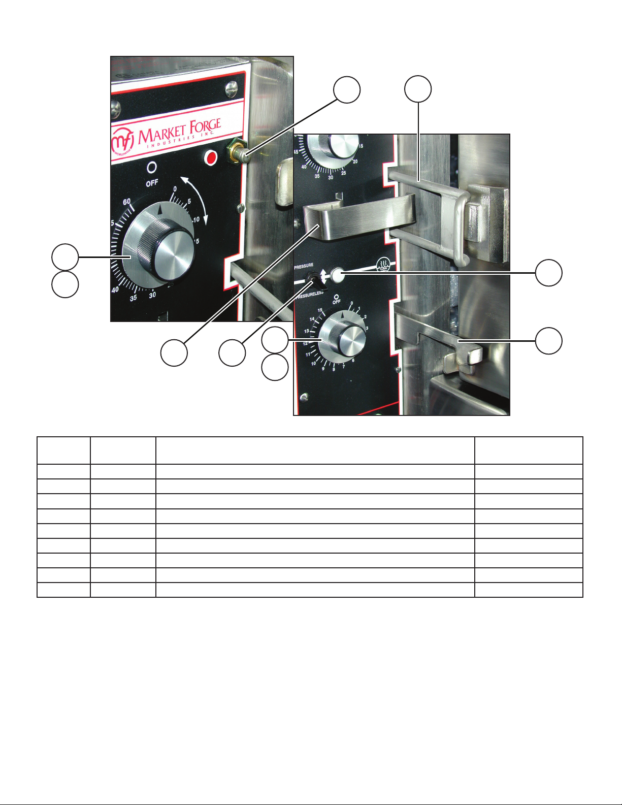
Fig 8. Front Control Panel
PART
ITEM
1 10-6859 MICRO SWITCH 1 (PER COMPARTMENT)
2 90-8338 ASSEMBLY, HANDLE LATCH AND BRACKET 1 (PER COMPARTMENT)
3 10-6291 TIMER, 60 MINUTE 1 (PER COMPARTMENT)
4 09-5259 TIMER, KNOB 1 (PER COMPARTMENT)
5 90-9215 HANDLE, CONTROL 1 (PER COMPARTMENT)
6 10-7927 TIMER, 15 MINUTE 1
7 10-7903 SWITCH, TOGGLE 2
8 91-5163 ASSEMBLY, LATCH, SECONDARY 1 (
9 10-5940 LIGHT, PILOT, WHITE LENS 2
NO. DESCRIPTION QTY.
PER COMPARTMENT)
19
 Loading...