

Page 1
MANUAL
2 A-PLUS STEAM COOKER
Form No.: S-2330
11/03
35 Garvey Street l Everett l MA l 02149
Tel: (617) 387-4100 l Fax: (617) 387-4456 l (800) 227-2659
E-Mail: CUSTSERV@mfii.com l Website: mfii.com
Page 2

PARAGRAPH
SECTION 1 INTRODUCTION
Operating Instructions ...............................................................................................................
A-Plus Cooker Facts on Parade ................................................................................................
Suggested Cooking Times ........................................................................................................
Basic Functioning ......................................................................................................................
SECTION 2 TROUBLE-SHOOTING
2.1 General .................................................................................................................................
2.2 Electrical Fault Isolation ........................................................................................................
SECTION 3 MAINTENANCE
3.1 General .................................................................................................................................
3.2 Preventive Maintenance .......................................................................................................
3.2.1 Drain Screen Cleaning and Removal....................................................................................
3.2.2 Safety Valve Check ..............................................................................................................
3.2.3 Inner Door Cleaning and Removal ........................................................................................
3.2.4 Door Wheel Lubrication .........................................................................................................
3.3 Steam Condenser Adjustment ..............................................................................................
3.4 Repair and Replacement ......................................................................................................
SECTION 4 ILLUSTRATED PARTS LIST
4.1 General .................................................................................................................................
4.2 Ordering Information ..............................................................................................................
TABLE OF CONTENTS
PAGE
1-1
1-3
1-4
1-7
2-1
2-1
3-1
3-1
3-2
3-2
3-2
3-2
3-2
3-2
4-1
4-1
FIGURE
SECTION 1 INTRODUCTION
1.1 A-Plus Door Latches ..............................................................................................................
1.2 A-Plus Control Panel ..............................................................................................................
1.3 Steam Condenser Adjustment ...............................................................................................
SECTION 2 TROUBLE-SHOOTING
2.1 Wiring Diagram A-Plus ...........................................................................................................
2.2 Schematic Diagram A-Plus .....................................................................................................
SECTION 3 MAINTENANCE
3.1 Safety Valve Check ................................................................................................................
3.2 Inner Door Removal ................................................................................................................
3.3 Door Wheel Lubrication ............................................................................................................
3.4 Steam Condenser Adjustment .................................................................................................
SECTION 4 ILLUSTRATED PARTS LIST
4.1 Controls and Steam Header ....................................................................................................
4.2 Detail "D" (50Hz Units Only) ....................................................................................................
4.3 Section B-B Secondary Latch ..................................................................................................
4.4 Section C-C Control Handle .....................................................................................................
TABLE
SECTION 1 INTRODUCTION
1.1 Suggested Cooking Times .......................................................................................................
SECTION 2 TROUBLE-SHOOTING
2.1 General Trouble-Shooting Guide .............................................................................................
2.2 Electrical Trouble-Shooting Guide ...........................................................................................
SECTION 3 MAINTENANCE
3.1 Preventive Maintenance ...........................................................................................................
SECTION 4 ILLUSTRATED PARTS LIST
4.1 Part List ...................................................................................................................................
LIST OF ILLUSTRATIONS
LIST OF TABLES
PAGE
1-1
1-1
1-2
2-5
2-5
3-2
3-2
3-3
3-3
4-2
4-3
4-3
4-3
PAGE
1-4
2-2
2-4
3-1
4-4
Page 3
SECTION 1 INTRODUCTION
OPERATING INSTRUCTIONS
A-PLUS STEAM COOKER
The A-PLUS may be used either:
a. A Steam Pressure Cooker in both compartments. (As a Pressure Cooker, it will
cook fresh and defrosted foods.)
b. A Convection Steam Cooker in the TOP compartment ONLY. (As a Convection
Cooker, it will defrost and cook frozen vegetables or 3/4" thick meat and seafood in
a minimal amount of time.)
PREHEATING COMPARTMENT
Before each initial operation of the cooker and at other times when the cooking
compartment is cold, a 5-minute preheating cycle is required.
1. Check steam supply to insure pressure.
a. Direct Steam - Turn on valve of external steam supply.
b. All other Units - Follow steam generator operating instructions inside cabinet base.
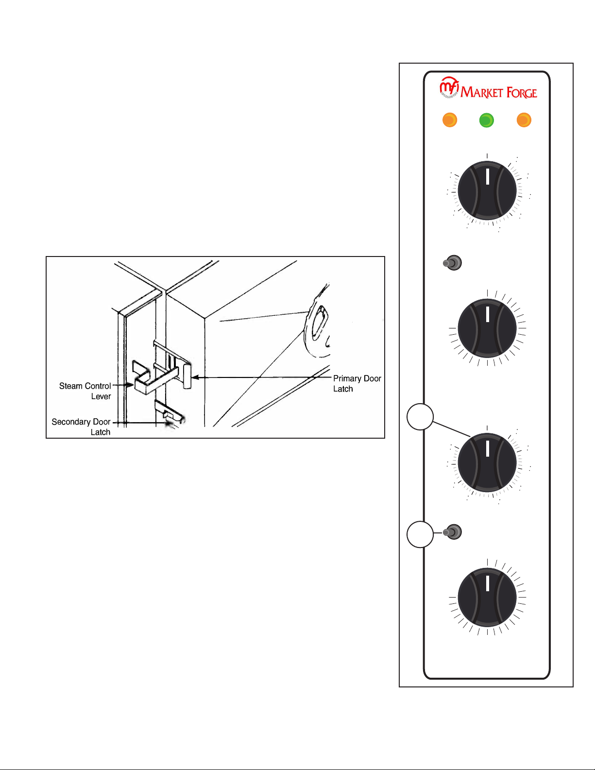
2. Close cooking compartment door to engage both door latches. If door doesn't latch,
turn door wheen counterclockwise until both latches are engaged. (See Fig. 1.1)
500 F
260 C
450 F
230 C
400 F
205 C
350 F
175 C
PRESSURE
PRESSURELESS
0
100 F
40 C
150 F
65 C
200 F
95 C
250 F
120 C
300 F
150 C
0
15
Figure 1.1 (Door Latches)
3. Seal cooking compartment by turning door wheel clockwise until wheel is hand tight.
CAUTION:
DON'T WRENCH DOOR WHEEL TIGHT!
Damage to door wheel and door gasket may result.
4. Ensure that automatic override switch is in AUTO (Down) position. (See Fig. 1.2, #2)
5. Set controls for cooking compartment to be preheated:
a. Top Compartment:
1. Place mode selector switch in the PRESSURE Cooking (Up) position.
2. Set 60-Minute Timer (Top) to 5-Minute position. (Go beyond 15-Minutes and
back to 5-Minutes for accurate timing.)
3. Pull steam control lever out and down. (See Fig. 1.1) Indicator light will come
on to show that the unit is operating. If pressure drops below 3 PSI (.2 kg/cm2),
adjust timer settings.
b. Bottom Compartment:
1. Ste 60-Minute timerto 5-Minute position.
2. Pull steam control lever out and down. (See Fig. 1.1) Indicator light will come
on to show that the unit is operating. If pressure drops below 3 PSI (.2 kg/cm2),
adjust timer settings.
6. At end of cooking cycle, steam control lever is released automatically, exhausting
steam and condensation from the compartment, and causing the buzzer to sound.
Turn off buzzer by setting timer to OFF position. (See Fig. 1.2 #1)
7. Allow pressure to return to 0 PSI. Loosen door by turning wheel counterclockwise.
Push primary door latch from door lip. Allow remaining steam to dissipate from the
120
105
90
75
A - PLUS
350 F
175 C
0
300 F
150 C
0
90
75
1
500 F
260 C
450 F
230 C
400 F
205 C
MANUAL
2
AUTO
120
105
Figure 1.2 (A-Plus Control Panel)
100 F
40 C
15
60
250 F
120 C
60
150 F
65 C
200 F
30
45
95 C
30
45
Page 1-1
Page 4
SECTION 1 INTRODUCTION
partially open door. Then, after determining that no water is flowing out under the bottom of the door, lift the secondary door latch and
open door fully.
NOTE: If automatic controls fail, place automatic override switch to MANUAL (Up) position and time manually.
CONVECTlON STEAM COOKING (Top Compartment Only)
Before loading the cooker, be sure compartment is hot If not hot, follow preheating
instructions.
1. Slide pans of frozen food onto pan supports in top cooking compartment
2. Close cooking compartment door to engage both door latches If door does not latch,
turn door wheel counterclockwise until both latches are engaged. (See Fig. 1.1)
3. Place cooking mode selector switch in PRESSURELESS COOKING (Down)
position.
4. Set 15-minute timer (Center) to required cookIng time.
5. Turn off buzzer which sounds to indicate cycle complete by setting timer dial to the
OFF position.
6. Loosen door by turning wheel counterclockwise. Push primary door latch from door
lip. Allow remaining steam to dissipate from partially open door Then, after
determining that no water is flowing under bottom of the door, lift the secondary door
latch up and open the door fully.
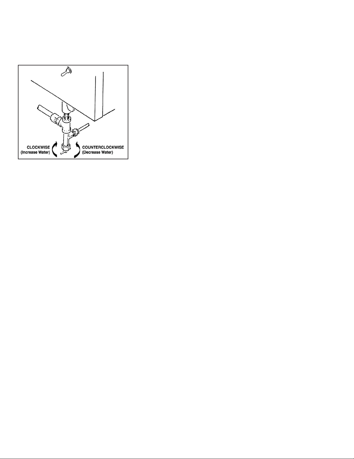
Figure 1.3 (Steam Condensor Adjustment)
PRESSURE COOKING (Both Compartments)
7. Unload by sliding pans of food from pan supports.
Before loading the cooker. be sure compartment is hot If not hot, follow preheating instructions.
1. Slide pans of food into either cooking compartment
2. Close cooking compartment door to engage both door latches If door does not latch, turn door wheel counterclockwise until both
latches are engaged. (See Fig. 1.1)
3. Ensure that automatic switch is in AUTO (Down) position. (See Fig. 1.2 #2)
4. Set controls for cooking compartment to be used
a. Top Compartment:
1. Place mode selector switch in the PRESSURE COOKING (Up) position.
2. Set 60-minute timer (Top) to required cooking time.
3. Pull steam control lever out and down.
b. Bottom Compartment
1. Set 60-minute timer to required cooking time.
2. Pull steam control lever out and down.
5. At end of cooking cycle, steam control lever is released automatically exhausting steam and condensate from the compartment by
causing the buzzer to sound. Turn off buzzer by setting timer to the OFF position. (See Fig. 2 #1)
6. Allow pressure to return to 0 PSI. Loosen door by turning door wheel counterclockwise. Push primary door latch from door lip. Allow
remaining steam to dissipate from the partially open door. Then, after determining that no water is flowing out under the bottom of the
door, lift the secondary door latch and open the door fully.
7. Unload by sliding pans of food from pan supports or shelves.
NOTE: If automatic controls fail, place automatic override switch in MANUAL (Up) position and time manually.
CLEANING
Consult steam generator instructions inside base for shut-down procedure. After each daily operating period, the A-PLUS should be
thoroughly cleaned with mild detergent, making sure compartment is left dry and door is open.
STEAM CONDENSER ADJUSTMENT
The steam condensing system for the A-PLUS Cooker adds cold water to the drain line at all times when the cooker is operating in the
convection (pressureless) mode. A manual flow control valve located underneath the boiler control box should be adjusted by the
operator as required to correct either of two symptoms which may occur during convection cooking.
1. Banging noise -Turn flow control valve counterclockwise to decrease the flow of condensing water. (See Fig. 1.3)
2. Steam billows into lower compartment -Turn flow control valve clockwise to increase flow of condensating water. (See Fig. 1.3)
Page 1-2
Page 5

SECTION 1 INTRODUCTION
A-PLUS COOKER
FACTS ON PARADE
1. Frozen vegetables should be cooked (6 pans 12" x 20" x 2'/2" (1/1-65mm) -7 1/2 # (3.4kg) maximum per
pan) in the PRESSURELESS COOKING MODE (perforated pans recommended).
2. Frozen entrees (6 pans 12" x 20" X2 1/2" (1/1-65mm maximum) should be defrosted and heated in the
PRESSURE COOKING MODE (perforated pans recommended).
3. Fresh foods (6 pans 12" x 20" X2 1/2" (1/1-65mm maximum) should be cooked in the PRESSURE
COOKING MODE.
4. Pressureless Cooking should only be used for frozen vegetables or short term defrosting.
5. All foods, except cakes and pastry, can be cooked in a steam cooking unit.
6. Steam cooked meals have greater nutritional value since they retain most of their vitamins and minerals.
7. Because foods are cooked faster by the higher temperature of steam cooking, they can be prepared closer
to serving time, insuring maximum freshness.
8. Steam cooked food has a higher percent yield -more portions per dollar spent.
9. Food may be served from the same pan in which it is steam cooked, thus reducing food breakage since
there is no extra handling or transferring of food from cooking pans to serving pans. It also reduces pot
washing tasks.
10. Some important advantages of steam cooking are: labor saving, reduced operating costs, space saving,
and the lifting of heavy stock pots is eliminated.
11. Rice and spaghetti products, if thoroughly wet at the start of the cooking process, are very easily prepared.
12. Foods such as potatoes, poultry, seafood and some meats may be blanched in the steam cooker, thus
reducing the total cooking time and grease absorption.
13. Fuel is used only when the steam cooking is in operation.
14. The steam cooker will loosen foods burned on pans making washing easier.
15. Solid pans are recommended when liquid is to be retained and perforated pans when liquid is not to be
retained.
16. Eggs may be cooked out of the shell if they are to be chopped, which eliminates peeling after steaming.
17. The steam cooker can be opened during the cooking period (by first releasing the steam pressure) to add
or remove items. If any time is lost, an adjustment may be made on the timer.
18. Steam cooking information, including recommended pan size and type, weight per pan, cooking times, and
pan yields are given on the following pages of this manual.
Page 1-3
Page 6
SECTION 1 INTRODUCTION
APPROX. RECOMMENDED PRESSURELESS APPROX. NO.
FROZEN 12" x 20" (1/1) TIMER COOKED
WEIGHT PERFORATED NUMBER SETTINGS SERVINGS
ITEM PER PAN PAN OF PANS MINUTES PER PAN
Asparagus
Spears 7 1/2 # (3.4kg) 2 1/2'' (65mm) 1-6 8-13 30-3oz. (85g)
Regular Green
Beans 6 # (2.7kg) 2 1/2'' (65mm) 1-6 8-13 25-3oz. (85g)
French Cut Green
Beans 6 # (2.7kg) 2 1/2'' (65mm) 1-6 4-10 25-3oz. (85g)
Lima Beans 7 1/2 # (3.4kg) 2 1/2'' (65mm) 1-6 12-15 30-3oz. (85g)
Broccoli 6 # (2.7kg) 2 1/2'' (65mm) 1-6 7-10 25-3oz. (85g)
Brussels Sprouts 7 1/2 # (3.4kg) 2 1/2'' (65mm) 1-6 9-14 30-3oz. (85g)
Carrots 6 # (2.7kg) 2 1/2'' (65mm) 1-6 7-12 25-3oz. (85g)
Cauliflower 6 # (2.7kg) 2 1/2'' (65mm) 1-6 7-12 25-3oz. (85g)
Cut Corn 7 1/2 # (3.4kg) 2 1/2'' (65mm) 1-6 5-10 30-3oz. (85g)
Mixed Vegetables 7 1/2 # (3.4kg) 2 1/2'' (65mm) 1-6 5-10 30-3oz. (85g)
Peas 7 1/2 # (3.4kg) 2 1/2'' (65mm) 1-6 5-10 30-3oz. (85g)
Spinach 9 # (4kg) 2 1/2'' (65mm) 1-6 Must be Defrosted 30-4oz. (85g)
Squash 7 1/2 # (3.4kg) 2 1/2'' (65mm) 1-6 Must be Defrosted 50-3oz. (85g)
RECOMMENDED PRESSURELESS APPROX. NO.
12" x 20" (1/1) TIMER COOKED
WEIGHT SOLID NUMBER SETTINGS SERVINGS
ITEM PER PAN PAN OF PANS MINUTES PER PAN
Lobster Tails 7-8 #
6-8 Oz. (170-225g) (3.2-3.6kg) 2 1/2" (65mm) 1-6 15-20 15-6oz. (170g)
Shrimp C.D.P. 16-20 # (7 1/2-9kg) 2 1/2" (65mm) 1-6 8-11 75-3oz. (85g)
Green Shrimp 16-20 # (7 1/2-9kg) 2 1/2" (65mm) 1-6 11-15 50-3oz. (85g)
Bulk Pack 3 1/2-4 #
Frozen (1.6-1.8kg) 2 1/2" (65mm)* 1-6 30-45** 10-6oz. (170g)
Bulk Pack 3 1/2-4 #
Defrosted (1.6-1.8kg) 2 1/2" (65mm)* 1-6 25-35** 10-6oz. (170g)
FROZEN VEGETABLES
FROZEN PREPARED ENTREES
* Perforated Pan
** Pressure Timer Setting
THE TOP COMPARTMENT OF THE A-PLUS COOKER has been specifically designed for frozen foods, yet may be instantly converted to
a 5 PSI (.33kg/cm
method. The bottom compartment is a standard pressure cooker only.
FOR PRESSURELESS COOKING of frozen foods:
a. Adjust selector to pressureless cooking.
b. Set 15-Minute Timer.
2
) pressure steam cooker by adjusting the selector switch. (6) standard 2 1/2" steam table pans may be used with either
FOR PRESSURECOOKING of other foods:
a. Adjust selector switch to pressure cooking.
b. Set 60-Minute Timer.
c. Pull steam control lever.
PRESSURELESS STEAM COOKING TIMER SETTINGS & PORTIONS
Page 1-4
Page 7
SECTION 1 INTRODUCTION
APPROX. RECOMMENDED PRESSURELESS APPROX. NO.
FROZEN 12" x 20" (1/1) TIMER COOKED
WEIGHT PERFORATED NUMBER SETTINGS SERVINGS
ITEM PER PAN PAN OF PANS MINUTES PER PAN
Snap or Waxed 1-3 15-20
Green Beans 6 # (2.7kg) 2 1/2'' (65mm) 4-6 20-25 25-30 3oz. (85g)
Beets 1-3 40-45
2" (50mm)
7 1/2 # (3.4kg) 2 1/2'' (65mm) 4-6 45-60 30-35 3oz. (85g)
Broccoli Stalks 1-3 10-15
1/2-3/4"(12-20mm) 6 # (2.72kg) 2 1/2'' (65mm) 4-4 15-20 25-30 3oz. (85g)
Sliced 1-3 18-21
Carrots 9 # (4kg) 2 1/2'' (65mm) 4-6 21-25 35-40 3oz. (85g)
Cauliflower Trimmed
1 1/2-2" Flower 1-3 10-15
(38-50mm) 6 # (2.72kg) 2 1/2'' (65mm) 4-6 15-20 30-35 3oz. (85g)
Corn on the Cob 1-3 10-12
Husked 1 doz. 2 1/2'' (65mm) 4-6 12-15 12
Cabbage 1-3 14-16
Head Cored 5 # (2.25kg) 2 1/2'' (65mm) 4-6 16-20 15-20 4oz. (115g)
Onions 1-3 10-18
2" (50mm)
6 # (2.72kg) 2 1/2'' (65mm) 4-6 15-30 25-30 4oz. (115g)
Peas 1-3 5-6
Shelled 5 # (2.3kg) 2 1/2'' (65mm) 4-6 7-8 25-30 34oz. (85g)
Potatoes 1-3 15-18
French Fry Cut 10 # (4.5kg) 2 1/2'' (65mm) 4-6 18-20 50-3oz. (85g)
Potatoes 1-3 20-25
Regular Cut 10 # (4.5kg) 2 1/2'' (65mm) 4-6 25-30 50-3oz. (85g)
Spinach 1-2 3-5 10-12
Clean Cut 3 # (1.4kg) 2 1/2'' (65mm) 3-4 4-6 3 3/4oz. (105g)
Squash 1-3 15-20
Winter Peeled 9 # (4kg) 2 1/2'' (65mm) 4-6 20-25 25-30 3oz. (85g)
Squash - Summer 1-3 8-12
Sliced 1" (25mm) 7 # (3.2kg) 2 1/2'' (65mm) 4-6 12-15 30-35 3oz. (85g)
Turnip 1-3 25-30
Diced 5 # (2.3kg) 2 1/2'' (65mm) 4-6 30-35 20-25 4oz. (115g)
APPROX. RECOMMENDED PRESSURELESS APPROX. NO.
FROZEN 12" x 20" (1/1) TIMER COOKED
WEIGHT PERFORATED NUMBER SETTINGS SERVINGS
ITEM PER PAN PAN OF PANS MINUTES PER PAN
Canned 1-3 4-5
Vegetables 7 # (3.4kg) 2 1/2'' (65mm) 4-6 5-8 25-30 34oz. (85g)
VEGETABLES
FRESH 5 PSI
VEGETABLES
CANNED
PRESSURE STEAM COOKING TIMER SETTINGS & PORTIONS
Page 1-5
Page 8

SECTION 1 INTRODUCTION
APPROX. RECOMMENDED PRESSURELESS APPROX. NO.
FROZEN 12" x 20" (1/1) TIMER COOKED
WEIGHT PERFORATED NUMBER SETTINGS SERVINGS
ITEM PER PAN PAN OF PANS MINUTES PER PAN
Chicken 1-3 18-25 Protein
Cut-Up 6 # (2.7kg) 2 1/2' (65mm) 4-6 25-30 15-20 2oz. (55g)
Chicken 1-2 45-55 Protein
4# Whole 3 Each 4" (100mm) 3-4 55-65 25-30 2oz. (55g)
Fowl 1-2 50-60 Protein
5# or More Whole 2 Each 4" (100mm) 3-4 65-75 20-25 2oz. (55g)
Fish 1-3 8-12
Fillets 3 # (1.4kg) 2 1/2'' (65mm) 4-6 10-15 12-15 2oz. (55g)
1-3 3-4
Frankforts 5 # (2.3kg) 2 1/2'' (65mm) 4-6 4-5 35-40 2oz. (55g)
Hamburgers 1-3 12-14
3 oz. (85g) 5 # (2.3kg) 2 1/2'' (65mm) 4-6 15-18 20-25 2oz. (55g)
Meatballs* 1-3 18-22 Protein
1 oz. (30g) 6 # (2.7kg) 2 1/2'' (65mm) 4-6 22-25 20-25 2oz. (55g)
1-3 35-40 Protein
Meatloaf* 15 # (6.8kg) 2 1/2'' (65mm) 4-6 40-45 50-60 2oz. (55g)
Pork Chops Loin 1-3 25-30 Protein
Bone 4 oz. (115g) 6 # (2.7kg) 2 1/2'' (65mm) 4-6 30-35 24 2oz. (55g)
Sausage 1-3 18-21
1 1/2 oz. (45g) 6 # (2.7kg) 2 1/2'' (65mm) 4-6 22-25 18-20 2oz. (55g)
Turkey Protein
Carcass 20-22 # (9-10kg) 2 1/2'' (65mm) 1-2 100-120 50-60 2oz. (55g)
Turkey 1-3 50-60 Protein
off Carcass 10-12 # (4.5-5kg) 2 1/2'' (65mm) 4-6 60-75 55-65 2oz. (55g)
APPROX. RECOMMENDED PRESSURELESS APPROX. NO.
FROZEN 12" x 20" (1/1) TIMER COOKED
WEIGHT PERFORATED NUMBER SETTINGS SERVINGS
ITEM PER PAN PAN OF PANS MINUTES PER PAN
Eggs 1-3 8-9 36
in Shell 3 doz. 2 1/2'' (65mm) 4-6 9-10 1 egg each
Eggs 1-3 6-7 48
Out of Shell 4 doz. 2 1/2'' (65mm) 4-6 7-8 1 egg each
Rice 1-2 22-24
Bulletin 16 4 # (1.8kg) 4" (100mm) 3-4 25-27 60-65 3oz. (85g)
Spaghetti 1-2 20-22
Bulletin 13 3 # (1.4kg) 4" (100mm) 3-4 23-26 40-45 4oz. (115g)
MEAT
POULTRY, FISH
MISCELLANEOUS
CANNED
extenders or 3 oz. (85g) total portion.
* Raw weight for Meatballs and Meatloaf including Hamburgers and extenders and yields 2 oz. (56g) protein plus
PRESSURE STEAM COOKING TIMER SETTINGS & PORTIONS
Page 1-6
Page 9

SECTION 1 INTRODUCTION
This service and parts section contains descriptive information. trouble-shooting procedures, maintenance information,
and parts identification for the A-PLUS Cooker. Only information for those electrical and plumbing systems which are
not included in the A Cooker, but are required for the A-PLUS are included.
1.1 DESCRIPTION
The model A-PLUS is a factory modified model A
Cooker equipped for operator selection of either
pressure or free-vented pressureless steam cooking
in the upper compartment. Double stacked,
independently controlled compartments are fitted
with single automatic controls. A separate steam
source required for operation is factory mounted
under the cooker with all steam, drain and electric
interconnections completed (Models A-PLUS E, APLUS G and A-PLUS SC). The cooker can also be
supplied on a cabinet containing plumbing controls
for direct connection to an existing steam source
(Model A-PLUS D).
1.2 BASIC FUNCTIONING
The upper compartment of the A-PLUS may be
converted from a pressure steam cooker to a
pressureless, free-vented steam cooker simply by
placing a mode selector switch in the required
position followed by setting a timer:
1. For pressure cooking, the compartment is
automatically sealed by the closing of an exhaust
valve and evacuation of air through a steam trap
as steam is injected. The compartment remains at
approximately 5 Ibs. steam pressure until the
operator-selected cooking duration ends (top
timer).
2. For pressureless cooking, the compartment
remains vented to the drain system while steam is
injected. In this manner a continuous flow of steam
circulates throughout the compartment and out the
exhaust for the cooking duration (center timer).
The lower compartment functions at all times as
described in 1 above and utilizes an independent
timer (bottom timer).
1.3 SERVICE
Should repairs be required, a network of authorized
service agencies is available to assist with prompt
service. A current Directory of Authorized Service
Agencies and service assistance may be obtained by
contacting:
Product Service Department
Market Forge
35 Garvey Street
Everett, Massachusetts 02149-4403
Telephone: (617) 387-4100
The model and serial numbers must be referenced
when corresponding with Market Forge.
Page 1-7
Page 10

SECTION 2 TROUBLE-SHOOTING
2.1 GENERAL
This Section contains trouble-shooting guide
information to assist service personnel in loacting the
general source of problems which may occur with the
A-PLUS COOKER. It is recommended that local
authorized service be obtained for assistance in
completeting the trouble-shooting procedures.
Table 2-1 serves as a general guide to troubleshooting. Before attempting to utilize this information,
service personnel should be thoroghly familiar with
the operating instructions and the function of all
controls in the operating instructions.
2.2 ELECTRICAL FAULT ISOLATION
Correction of an electrical failure first requires
isolation of the fault to a single circuit or components.
In most cases the nature of the fiure and its effect
upon the operation of the cooker will be sufficient to
isolate it to one or more circuit elements. Tble 2-2 is
provided as a guide for isolating electrical faults
which may occur in operation of the upper
compartment. Wiring Diagram, Figure 2-1 and
scematic diagram Figure 2-2 are provided for
locating the source of electrical failures.
Page 2-1
Page 11

SECTION 2 TROUBLE-SHOOTING
PROBLEM
PROBABLE CAUSE REMEDY
a. Power to A-Plus Cooker off.
a. Locate external circuit breaker for incoming
power and place in ON position.
b. Selector Switch in Pressureless Cooking
b. Place in Pressure Cooking Position.
Position.
c. 60-Minute Timer not set.
c. Set 60-Minute Timer.
a. Power to A-Plus Cooker off. a. Locate external circuit breaker for incoming
power and place in ON position.
b. Selector Switch in Pressure Cooking Position. b. Place in Pressureless Cooking Position.
c. 15-Minute Timer not set. c. Set 15-Minute Timer.
a. Power to A-Plus Cooker off. a. Locate external circuit breaker for incoming
power and place in ON position.
b. Indicator Light burned out. b. Replace light.
c. Faulty wiring. c. Inspect condition of wire, and tightness of all
connections. Correct as needed.
d. Faulty Selector Switch. d. Replace Switch.
e. 60-Minute Timer Contact Faulty. e. Replace Timer.
f. Faulty Microswich. f. Replace Switch.
a. Power to A-Plus Cooker off. a. Locate external circuit breaker for incoming
power and place in ON position.
b. Indicator Light burned out. b. Replace light.
c. Faulty wiring. c. Inspect condition of wire, and tightness of all
connections. Correct as needed.
d. Faulty Selector Switch. d. Replace Switch.
e. 15-Minute Timer Contact Faulty. e. Replace Timer.
a. Defective 60-Minute Timer Motor or Contact. a. Replace Timer.
b. Defective Steam Exhaust Valve. b. Replave Valve.
a. Defective 15-Minute Timer Motor or Contact. a. Replace Timer.
b. Defective Steam Inlet Solenoid Valve. b. Replave Valve.
a. Compartment door not closed. a. Securely latch door closed.
b. No steam entering steam line. b. Check steam generator and pressure producing
valve for proper operation.
c. Faulty or jammed door interlock switch. c. Adjust or replace switch.
d. Faulty steam inlet solenoid valve. d. Replace valve.
NOTE: * Pertains to upper compartment only.
6. PRESSURELESS COOKING MODE FAILS TO STOP.*
7. STEAM FAILS T ENTER COMPARTMENT IN PRESSURELESS COOKING MODE
(WITH INDICATOR LIGHT ON).*
COOKING POSITION AND 60-MINUTE TIMER SET.*
4. INDICATOR LIGHT FAILS TO LIGHT WITH SELECTOR SWITCH IN PPRESSURELESS
COOKING POSITION AND 15-MINUTE TIMER SET.*
5. PRESSURE COOKING MODE FAILS TO STOP.
2. INDICATOR LIGHT FAILS TO LIGHT IN PRESSURELESS COOKING MODE.*
3. INDICATOR LIGHT FAILS TO LIGHT WITH SELECTOR SWITCH IN PPRESSURE
TABLE 2-1
GENERAL TROUBLE-SHOOTING GUIDE
1. INDICATOR LIGHT FAILS TO LIGHT IN PRESSURE COOKING MODE.*
Page 2-2
Page 12

SECTION 2 TROUBLE-SHOOTING
PROBLEM
PROBABLE CAUSE REMEDY
a. Improperly adjusted cold water flow control
a. Adjust valve. Increase flow of steam,
valve.
decrease for banging.
a. Faulty inlet solenoid steam valve
a. Replace valve.
b. Defective or jammed door interlock switch.
b. Clean or replace switch.
c. Defective manual steam valve.
c. Check valve and mechanism.
a. Insufficient steam input from steam generator.
a. Check generator for 15PSI output. Adjust
b. Faulty pressure gauge.
b. Replace gauge
c. Faulty steam exhaust valve.
c. Check vavle and mechanism.
d. Faulty relief valve.
d. Replace valve.
a. Faulty microswitch.
a. Replace microswitch.
b. Faulty buzzer.
b. Replace buzzer.
a. Faulty 15-Minute timer.
a. Replace 15-Minute timer.
b. Faulty buzzer.
b. Replace buzzer.
a. Air in cooking compartment.
a. Replace steam trap.
b. Low steam pressure.
b. See item 7.
a. Defective relief valve.
a. Replace relief valve.
a. Plugged drain screen.
a. Clean.
10. NO STEAM PRESSURE GAUGE READING COOKING MODE.
11. BUZZER FAILS TO SOUND AT END OF PRESSURE COOKING DURATION.
9. STEAM ENTERS COMPARTMENT AT ALL TIMES.
12. BUZZER FAILS TO SOUND AT END OF PRESSURELESS COOKING DURATION.
(WITH INDICATOR LIGHT OFF).*
13. COOKING COMPARTMENT FAILS TO REACH COOKING TEMPERATURE IN PRESSURE
COOKING MODE.
14. IN PRESSURE COOKING MODE PULLING UP ON SAFETY VALVE KNOB FAILS TO
CAUSE PRESSURE DROP.
15. IN PRESSURE COOKING MODE TOP COMPARTMENT ACCUMULATES WATER.
NOTE: * Pertains to upper compartment only.
COMPARTMENT IN PRESSURELESS COOKING MODE.
TABLE 2-1 Continued
GENERAL TROUBLE-SHOOTING GUIDE
8. BANGING SOUND OR STEAM ENTERING BOTTOM COMPARTMENT WITH TOP
Page 2-3
Page 13

SECTION 2 TROUBLE-SHOOTING
FAILURE LOCATION
1. WILL NOT OPERATE IN EITHER PRESSURE
A. INCOMING POWER.
OR PRESSURELESS COOKING MODE.
B. SELECTOR SWITCH.
C. WIRING.
2. OPERATES IN PRESSUREMODE BUT NOT IN
A. SELECTOR SWITCH.
PRESSURELESS MODE.
B. WIRING.
C. 12-MINUTE TIMER.
D. STEAM SOLENOID VALVE.
3. OPERATES IN PRESSURELESS MODE BUT NOT
A. SELECTOR SWITCH.
IN PRESSURE MODE.
B. WIRING.
C. 60-MINUTE TIMER.
4. INDICATOR LIGHT OFF IN EITHER MODE.
A. INDICATOR LIGHT.
B. WIRING.
5. INLET SOLENOID VALVE FAILS TO OPEN BUT
A. DOOR INTERLOCK SWITCH.
INDICATOR LIGHT IS ON IN PRESSURELESS
B. INLET SOLENOID VALVE COIL.
MODE.
C. WIRING.
6. BUZZER FAILS TO SOUND AT END OF EITHER
A. 15-MINUTE TIMER.
PRESSURE OR PRESSURELESS COOKING
B. BUZZER.
MODE.
C. WIRING.
D. MICROSWITCH.
7. WILL NOT STOP OPERATING IN PRESSURE
A. 60-MINUTE TIMER MOTOR.
MODE.
8. WILL NOT STOP OPERATING IN
A. 15-MINUTE TIMER MOTOR.
PRESSURELESS MODE.
TABLE 2-2
ELECTRICAL FAULT ISOLATION GUIDE - UPPER COMPARTMENT
Page 2-4
Page 14

SECTION 2 TROUBLE-SHOOTING
Page 2-5
Page 15

SECTION 3 MAINTENANCE
3.1 GENERAL
3.1 GENERAL
This section contains both preventive and corrective
This section contains both preventive and corrective
maintenance information required for the A-PLUS
maintenance information required for the A-PLUS
Cooker.
Cooker.
Preventive maintenance may be performed by
Preventive maintenance may be performed by
maintenance personnel at the establishment in which
maintenance personnel at the establishment in which
the cooker is installed. It is recommended that user
the cooker is installed. It is recommended that user
personnel never attempt to make repairs or
personnel never attempt to make repairs or
replacements to the equipment without the
replacements to the equipment without the
assistance of authorized service. Assistance in
assistance of authorized service. Assistance in
service
service
TABLE 3-1
PREVENTIVE MAINTENANCE
methods or a current Directory of Authorized Service
methods or a current Directory of Authorized Service
Agencies may be obtained from Market Forge.
Agencies may be obtained from Market Forge.
3.2 PREVENTIVE MAINTENANCE
3.2 PREVENTIVE MAINTENANCE
A good preventive maintenance program begins with
A good preventive maintenance program begins with
the daily cleaning procedure described in Table 3-1.
the daily cleaning procedure described in Table 3-1.
Additional preventive maintenance operations are
Additional preventive maintenance operations are
presented in this section .
presented in this section .
FREQUENCY
DAILY
WEEKLY
MONTHLY
PROCEDURE
1. CLEANING:
Remove pan supports, shelves and shelf supports, and thoroughly
wash and rinse interior of both cooking compartments. Be sure to
drain screen, located inside top compartment, is clear of all food
particles.
1. SAFETY VALVE CHECK:
With upper compartment in operation in te pressure cooking
mode, lift up on level of forward mounted safety vavle. Repeat for
rear mounted safety valve. Steam should flow freely from outlet
port, verifying proper functioning and clearing of accumulated
deposits in valves.
2. INNER DOOR CLEANING:
Remove inner door from both compartments. Wash inner door and
inside of outer door with mild detergent, rinse and reassemble.
1. DOOR WHEEL LUBRICATION:
Check door hand wheel rotation for ease of motion. If wheel resits
rotation when door is unlatched, lubrication is required. Remove
inner door and apply graphite lubrication to screw threads.
Page 3-1
Page 16

SECTION 3 MAINTENANCE
3.2.1 DRAIN SCREEN CLEANING & REMOVAL
The drain screen inside the top compartment is
provided to prevent blockage of the drain line. It must
be kept clean at all times by scrubbing daily with a
stiff bristle brush.
WARNING
A plugged drain may cause compartment flooding,
resulting in overflow of scalding water when door is
opened.
Should the drain screen require removal due to
excessive blockage or damage, the truss head screw
is loosened and the screen slipped out. The screen
must be in position, completely covering the lower
drain opening, prior to reuse of the A-PLUS.
3.2.2. SAFETY VALVE CHECK
The safety valves are protective devices which
automatically relieve excessive pressure (above 8
PSI) in the unlikely event of equipment malfunction.
Manual opening of the valves is also possible and
should be done once a week to assure valves are
clear and mechanically sound.
1. Place upper cooker compartment into operation in
the pressure mode and allow pressure to build to
about 4 PSI.
3.2.4 DOOR WHEEL LUBRICATION
The door wheel includes the externally mounted
wheel and built-in screw mechanism. Rotation of the
door wheel should be checked monthly for ease of
motion. If the wheel grinds or is difficult to turn, the
screw should be lubricated with graphite followed by
rotation of the wheel to transfer lubricant into threads
in door.
3.3 STEAM CONDENSER ADJUSTMENT
The drain and exhaust plumbing assembly nfor the
A-PLUS Cooker is located inside the cabinet base
under the cooking compartments. In addition to the
cold water steam condensing system included with
the boiler (or direct steam connection plumbing), an
additional steam condensing circuit is supplied in
boilers used with the A-PLUS Cooker. This circuit
functions automatically at all times when the cooker
is operating in the Pressureless mode.
To adjust the amount of additional cold water
admitted to the drain line, a second cold water
solenoid valve is included with a flow control valve
connected to the outlet side. The manual flow control
valve is located underneath the boiler control box as
shown in (Figure 3.1).
2. Pull up on safety valve lever for forward-mounted
valve (closest to manifold box onleft side of
cooker). Flow of steam from the valve outlet
verifies correct manual valve function and clears
exhaust passage.
NOTE
Steam is not present at relief valve until steam trap
has evacuated all air from the cooker compartment.
Presence of adequate steam should be checked (4-5
psi on gauge) before checking valve.
3. Repeat step 2 for rear-mounted valve.
3.2.3 INNER DOOR REMOVAL & CLEANING
The door assembly includes an outer door with
mounted hand wheel and an inner door with sealing
gasket. The inner door parts should be cleaned
weekly to ensure proper sealing against
compartment opening.
1. With door opened and hand wheel turned to full
clockwise position, grasp tabs and lift inner door
up and away from door.
2. Wash inner doors, gaskets and inside of outer
door with mild detergent, rinse and reassemble.
The manual valve is properly adjusted when the
drain operates silently and without steam backing up
into the lower compartment when the upper
compartment is operating in the Pressureless mode.
Adjustment characteristics are as follows:
1. Steam enters lower compartment condensing
water flow must be increased by turning valve
clockwise (as viewed from above), until steam is
eliminated.
2. Banging sound in drain line condensing water flow
must be decreased by turning valve counterclockwise until silent operation is achieved.
3.4 REPAIR AND REPLACEMENT
Section 4 of this manual contains a listing of
replaceable parts and associated illustrations of parts
specifically used in the A-PLUS Cooker, but not in
the A Cooker. Disassembly procedures for A-PLUS
parts will be obvious from the illustrations.
Page 3-2
Page 17

SECTION 4 ILLUSTRATED PARTS LIST
4.1 GENERAL
This section contains a listing of all replaceable parts
of the A-PLUS Cooker, specifically required for the APLUS. The parts are identified in illustrations and
keyed to an accompanying parts list. Modification
parts required for use with the steam generator or
steam direct connection plumbing are also listed.
Parts list contain the figure index number, the Market
Forge part number and an abbreviated description.
4.2 ORDERING INFORMATION
Orders for repair parts should be directed to the
nearest authorized parts distributor. Contact the
factory for a current Market Forge Authorized Parts
Distributor List (see sub-section 1.3).
All orders should contain the Market Forge part
number(s), the part description(s), the model and
serial numbers.
Page 4-1
Page 18

SECTION 4 ILLUSTRATED PARTS LIST
Figure 4.1 (Side View) Controls and Steam Header
Page 4-2
Page 19

SECTION 4 ILLUSTRATED PARTS LIST
Figure 4.2 Detail "D" (50Hz Units Only)
Figure 4.3 Section B-B Secondary Latch Figure 4.5 Control Panel Front View
Figure 4.4 Section C-C Control Hadle
Page 4-3
Page 20

SECTION 4 ILLUSTRATED PARTS LIST
No. Part No. Description No. Part No. Description
1 Ref. Assy., Weldment, Body, Enamel 44 08-3415 Bolt, Eye, W INut! 8-32
Ref. Assy., Weldment, Body, St. St. 45 90-9952 Angle, Lift, Operating, Arm
2 91-3308 Assy., Strainer 46 10-1761 Screw, Truss No., 8-32x318 Lg.
3 90-2434 Assy., Valve 47 10-3360 Elbow, Compression, 1181.P.S. x3116 O.D.
4 10-6156 Trap, Steam 48 90-8141 Tee, Rework
5 90-9211 Assy., Arm, Operating Valve 49 10-2972 Rivet, Pop, 118 Dia. x .232 Lg.
6 10-2756 Spring, Synchronization 50 Ref Loctite, Screwlock
7 90-9215 Handle, Control 51 10-1790 Screw, Hex Hd., 114-20x718 Lg., St. St.
8 90-8338 Assy., Handle, Latch & Bracket 52 95-3631 Spacer, 9132 Lg.
9 10-2755 Spring, Arm, Operating 53 91-5165 Spring, Torsion, Latch, Secondary
10 90-8963 Tubing, Copper, 3/16" O.D. x 18" Lg. 54 10-2508 Washer, Lock, 114-, St. St.
11 08-4813 Adaptor 90°, 318 N.P.T. Steam Trap 55 91-5161 Housing, Latch, Secondary
12 10-2549 Retainer, Bolt, **10 56 10-2412 Washer, Plain, 3/8 Ni. PJ.
13 10-3761 Nipple,3141.P.S. 57 91-5163 Arm, Latch, Secondary
14 09-5259 Knob, Timer 58 10-2403 Washer, Flat, 1/4 St. St.
15 Ref. Plate, Name, Serial Number 59 10-2019 Screw, Mach., Truss Hd.
16 10-4261 Plug, Button, 7/8" Dia. Hole 60 91-5168 Nut, Spacer
17 10-4107 Nut, Type J, 8-32 61 Ref. Loctite #24205
18 Ref. Seal. N.S.F. 62 08-6343 Relay, General Purpose, 240 V.
19 Ref. Label, Caution When Washing -Do Not 63 10-9174 Relay, Power Midget
Hose Down 64 08-6344 Socket, Screw Relay, 240 V.
20 91-5173 Assy., Weldment, Bracket, Relay 240V 65 10-9175 Socket
21 90-9238 Assy., Enclosure, Cover, Top, Painted 66 08-1201 Clamp, Hose, Double Tang
90-9237 Assy., Enclosure, Cover, Top, Polished 67 08-1202 Fitting, Hose, Nipple, Male 1" I.D.
22 90-9187 Enclosure, Support Bottom Painted Hose x 3/4 N.P.T.
90-9186 Enclosure, Support Bottom Polished 68 10-9262 Plate, Name, Identification, 120 V.
23 90-9185 Enclosure, Side Back, Painted 91-3716 Plate, Name, Identification, 240 V.
90-9184 Enclosure, Side Back, Polished 69 08-4850 Tubing, P.V.C., Clear, 1" I.D.x11/4 O.D.
24 10-4741 Valve, Safety, 314, 8 Ibs., Bronze 70 10-1949 Screw, Pan No., #6, Type "A", 3/8 Lg.
10-4742 Valve, Safety, 314, 8 Ibs., Bronze Satin 71 09-5242 Knob, Timer
25 10-1059 Elbow, Street, 90°, 3141PS, Chrome PI. 72 10-2948 Rivet, Pop, Domed No.118 Dia.
10-2830 Elbow, Street, 90°, 314 IPS, M.I. 73 10-2858 Elbow, Compression, 90°, 1/4 O.D. x
26 90-9189 Enclosure, Panel Cover, Painted 1 /8 I.P .S.
90-9188 Enclosure, Panel Cover, Polished 74 90-9217 Assy., Guide Bracket & Micro Switch
27 91-5192 Assy., Door & Hinge, Painted 75 10-1652 Pin, Cotter, 1/16 Dia. x 1" Lg., St. St.
91-5193 Assy., Door & Hinge, Polished 76 *90-8138 Assy., Door & Lubrication Procedure
28 10-2841 Elbow, 90°, 3141.P.S., M.I. 77 10-9277 Spring, Holddown, Midget Relay
10-1053 Elbow 90°, 314 I.P.S., Chrome PI. 78 90-9195 Insulation, Buzzer
29 10-1742 Screw, Truss HO., 10-24 x 314 Lg. 79 10-6682 Buzzer, 120 V,
30 91-5444 Assy., Control Panel, A-Plus, 120V., 60Hz. 10-6665 Buzzer, 240 V.
91-5445 Assy., Control Panel, A-Plus, 240V., 50Hz. 80 10-5997 Solenoid, 120 V.
31 10-1812 Screw, Mach., Rd. Hd., 10-32 x 112 Lg. 10-6881 Solenoid, 240 V.
32 10-2432 Washer, Flat, **10 Ni., PI. 81 90-8905 Rod, Push, Solenoid
33 10-2328 Nut, Stop, 114-20 82 10-5678 Clip, Cable, Plastic
34 10-2422 Washer, Flat, 114 Ni. PI. 83 Ref. Tape, Electrical, 3/4" Wide
35 10-2500 Washer, Lock, 114 Cad. PI. 84 *08-5829 Label, Reduced Wriing Diag.
36 10-1701 Screw, Mach., Rd. Hd., 114-20x318, Cad. PI. 85 --37 10-2154 Screw, Pan Hd., Type "B", 112 Lg. Cad. PI. 86 10-2160 Screw, Truss Hd., 10-32 x 3/8 Lgo
38 10-2124 Screw, Cap, Hex Hd., 318-16x1 Ye Lg., St. St. 87 10-2505 Washer, Lock, #10
39 10-2503 Washer, Lock. 318, Cad. PI. 88 10-2523 Washer, Lock, External Tooth 1/4"
40 10-1967 Screw, Shoulder, 114-20 89 10-2336 Nut, Hex, Mach., 1/4-20 St. St.
41 10-2521 Washer, Lock, Hel. Spiral Type, **8, Ni. PI. 90 10-1932 Screw, Mach., Rd. Hdo, 6-32 x 7/8 Lg.
42 10-1865 Screw, Rd., Hd., 8-32x1 '/4 Lg. 91 08-4843 Assy., Hose, Teflon, W/Braid St. St.
43 10-2330 Nut, Nex, 8-32 92 91-6204 Gasket, Valve Body, 1 /8 Thick
* NOT SHOWN.
Parts List
Page 4-4
Page 21

SECTION 4 ILLUSTRATED PARTS LIST
No. Part No. Description No. Part No. Description
93 10-3511 Compound, Sealing, Gasket 113 90-4946 Plate, Insulation, Microswitch
94 10-3669 Nipple, 3/410PoS. x 13/4 Lg. 114 10-1883 Screw, Mach., Rd, Hd., 6-32 x 1" lg.
95 10-3670 Tee, Reducing, Screwed, 3/4XV2XV2 115 10-2515 Washer, lock #6
96 90-7100 Nipple, Close, V2 I.PoSo 116 10-2337 Nut 6-32
97 10-8958 Name Plate, A-Plus 117 09-6431 Switch, Micro
98 10-3756 Elbow Street 3/4 10PoSo 118 10-2420 Washer #6, 156 I.D. x 375 O.D.
99 10-2847 Nipple, Close, 3/4 I.PoS. 119 *10-4287 Rap, Tie
100 10-3721 y Branch, 45°, Screwed, 1- loP oSo 120 *10-0753 Rack, Pan, Side (Top Comp)
101 10-3479 Bushing, Outside Hex, 13/4 loP oSo 121 *10-0755 Rack, Pan, Side (Top Comp)
102 10-2347 Receiver, Stud, 3/16 122 10-4748 Gauge, Pressure
103 10-4393 Nipple, Close, 1" I.PoSo 123 10-6293 Timer, 1 Hour 240 V 50Hz
104 10-1003 Reducer, Screwed 10-6291 Timer, 1 Hour 120 V 60Hz
105 *Ref. Wiring Drag & Schematic 124 09-6468 Timer, 15 Minte 240 V 50Hz
106 *Ref. Wire Lead Schedule 10-7927 Timer, 15 Minte 120 V 50Hz
107 91-3093 Ass yo, Header, Steam 125 10-6880 Lamo Inidcator, RCD 230 V
108 10-8920 Nut, 3/4-. St. St. 10-5499 Lamo Inidcator, Red 125 V
109 10-8918 Washer, Rubber, Neoprene, 1 V2- O.Do, 126 10-6876 Light, Pilot, White Lens 240 V
1" I.Do 10-5940 Light, Pilot, White Lens 120 V
110 91-3174 Washer, St St 1 1/161D x 13/4 OoDo 127 10-7903 Switch Toggle
111 95-3095 Assy., Piping, Jet 128 10-4424 Bezell, Name Plate
112 91-6205 Washer, 1 V2 O.D. x 1-I.D. x Ve thick 129 10-6859 Switch, Micro
Parts List (Continued)
* NOT SHOWN.
Page 4-5
 Loading...