

Page 1

OWNER’S MANUAL
MODEL A COOKER
Form Number: S-5099 REV: B 07/06
Printed in U.S.A. 35 Garvey Street l Everett l MA l 02149
Tel: (617) 387-4100 l Fax: (617) 387-4456 l Outside MA Fax: (800) 227-2659
E-Mail: CUSTSERV@mi.com l Website: www.mi.com
Page 2

TABLE OF CONTENTS
INTRODUCTION
Your “Set it and Forget it” Market Forge Model A
Steam Cookers ....................................1
How to use this manual .....................................................................................................1
Ordering Information .........................................................................................................1
INSTALLATION INSTRUCTIONS
Installation of the pedestal base .......................................................................................2
OPERATING INSTRUCTIONS
Model A Compartment Steam Cooker ...............................................................................
Preheating Manual Controls ..............................................................................................3
Preheating Automatic Controls
..........................................................................................3
Basic Operating Instructions for Automatic Controls ..........................................................4
Basic Operating Instructions for Manual Controls ..............................................................4
Helpful Hints ......................................................................................................................5
A Cooker Facts on Parade
Suggested Cooking Times
................................................................................................5
.................................................................................................6
3
MAINTENANCE
General ..............................................................................................................................9
Preventive Maintenance ....................................................................................................9
Drain Screen Cleaning and Removal ................................................................................9
Safety Valve Check ............................................................................................................9
Inner Door Cleaning and Removal ....................................................................................9
Door Wheel Lubrication .....................................................................................................10
Steam Condenser Adjustment
...........................................................................................10
Door Assembly Instructions ................................................................................................10
To replace a worn or damaged door gasket ......................................................................11
LLUSTRATED PARTS LIST
Ordering Information ..........................................................................................................11
Notes for pages 12 through 17 ...........................................................................................11
Illustrated Parts List for pages 15 through 17 ....................................................................12
Main Assembly, Automatic and Manual Controls ...............................................................15
Control Panel .....................................................................................................................16
Control Box Assembly, Automatic and Manual Controls .....................................................17
Door Assembly ...................................................................................................................18
Header, Steam and Exhaust Assembly .............................................................................19
ELECTRICAL INFORMATION
2 Compartment Wiring Diagram ........................................................................................21
2 Compartment Schematic Diagram ...................................................................................22
3 Compartment Wiring Diagram ........................................................................................23
3 Compartment Schematic Diagram ...................................................................................24
4 Compartment Wiring Diagram ........................................................................................25
...................................................................................26
4 Compartment Schematic Diagram
%8//(7,1
...................................................................................2
i
i
Page 3

INTRODUCTION
YOUR “SET IT AND FORGET IT’ MARKET FORGE MODEL A STEAM COOKERS are the ultimate in steam
cooking advancement and were developed through extensive research and engineering skills to satisfy an ur-
gent demand for an easy-to-operate, east-to-service steam cooker.
Independently controlled cooking compartments constitute a remarkable and superior feature.
Each compartment can be used alone, or all three can be employed simultaneously, because each has it’s own
timing, steam control and signal devices.
The careful factory workmanship of Market Forge craftsman in developing this newest scientic triumph in steam
cooking equipment is your guarantee of efcient, dependable performance.
HOW TO USE THIS MANUAL:
This manual contains maintenance and service instructions for the automatic and manuals A cooker. The ex-
ploded views of components are sids to identify, disassemble and assemble parts. The parts listings provided
information necessary to order the correct replacement parts when needed. (When requesting parts and service
always give the model and serial number of you unit.) The serial number is located on the left side under the bezzel on the control panel, or on the very top (roof) of the unit. The boiler serial number is located inside the front
panel. A listing of Factory Authorized Service Agencies who maintain Market Forge equipment will be supplied
without charge upon request.
ORDERING REPAIR PARTS:
The following information provided below are steps that should be taken when reordering replacement parts:
1.
Quantity, part number and description of part.
2.
Model and serial number for which the part is required.
3.
Please specify which type of shipping method preferred. If this information is not furnished we will ship the
best and most economical way. Note: All part orders received before 2:00 PM/EST are shipped the same day
the order is received.
1
Page 4
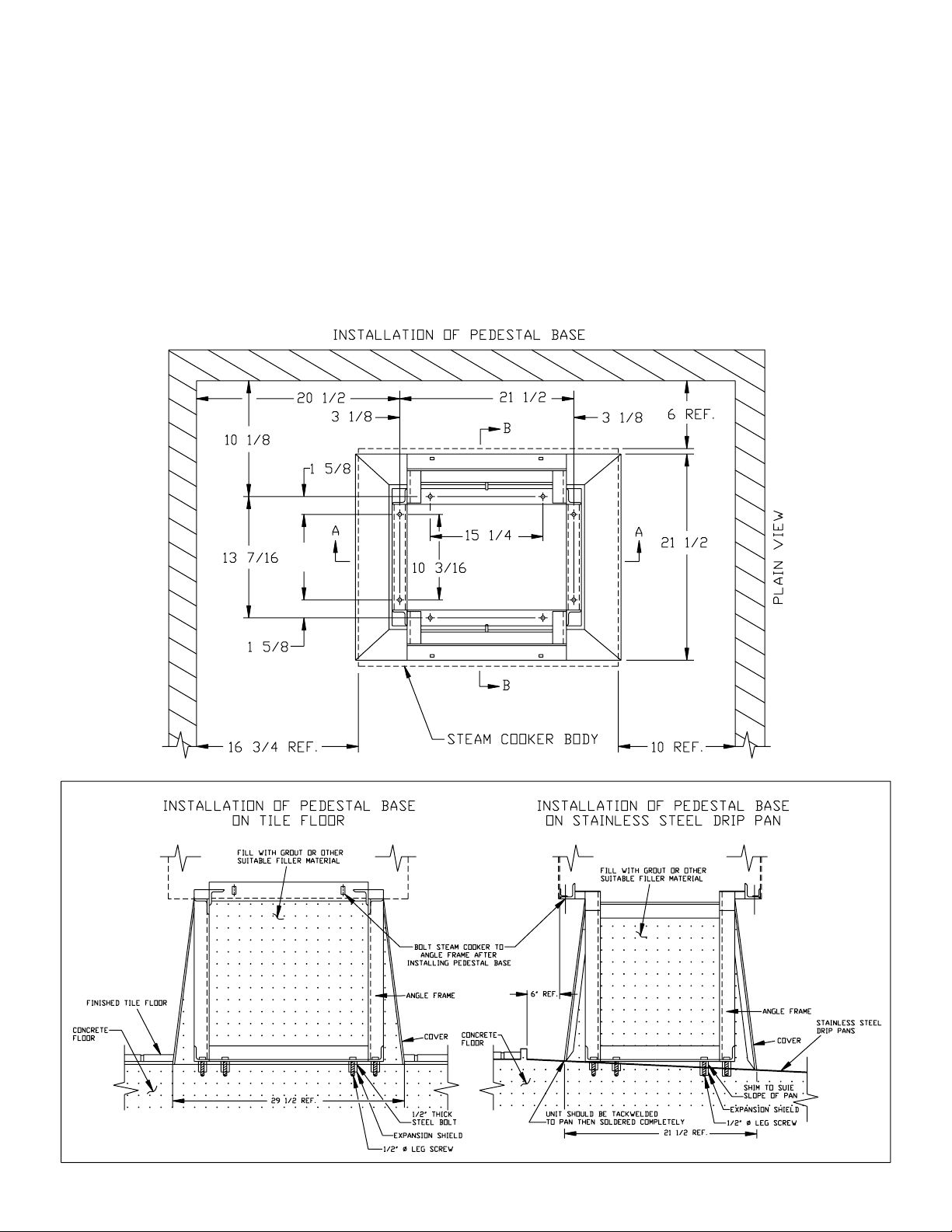
INSTALLATION INSTRUCTIONS
INSTALLATION OF THE PEDESTAL BASE:
Drop angle iron frame inside stainless steel cover. Place frame in position and secure the oor by using eight
1.
1/2” lag screws.
NOTE: Be sure that angle iron frame is level. If not, shim where necessary.
Fill with grout (cement).
2.
NOTE: If base is being mounted on a stainless steel drip pan, cover should be tackwelded to stainless steel
drip pan, then soldered to seal joint.
Bolt steam cooker to angle iron frame after installing pedestal base.
3.
2
Page 5
OPERATING INSTRUCTIONS
MODEL A COMPARTMENT STEAM COOKER:
1. Be sure that steam pressure is at the unit.
Direct Steam - Turn on external steam supply valve.
a)
All other Units - Follow steam generator operating
b)
instructions on control box cover plate inside
cabinet base.
Be sure that 1
c)
to the unit.
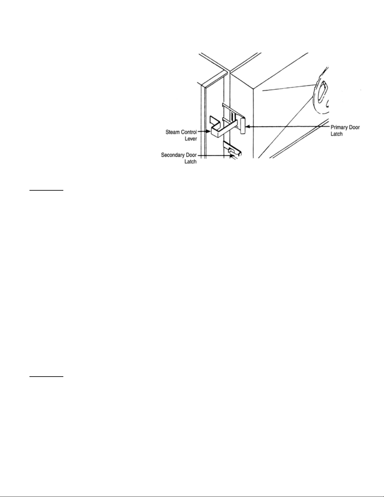
PREHEATING-MANUAL CONTROLS:
Close compartment door engaging both
1.
door latches. If door does not latch, turn
door wheel counterclockwise until both
latches are engaged.
Seal cooking compartment door by turning door wheel clockwise until wheel is hand tight.
2.
CAUTION: Do not wrench door wheel tight. This action can cause needless damage to both the door
wheel and door gasket over a period of time.
Start preheating by pulling steam control lever out and down.
3.
NOTE: Always start on compartment at a time. Each compartment has an individual steam control and is oper-
ated independently.
When pressure gauge indicates a minimum of 3 PSI, set timer at 5 minutes by going beyond 15 minutes and
4.
back to 5 minutes for accurate timing.
15 volt connection has been made
Compartment timer will sound to end preheating.
5.
Release steam control valve by lifting lever.
6.
Allow time for steam and condensate to leave the compartment before opening the door.
7.
Allow pressure to return to 0 PSI. Loosen door by turning wheel counter clockwise. Push primary door latch
8.
from door lip. Allow remaining steam to dissipate from the partially open door. Then, latch, and open the door
fully.
PREHEATING-AUTOMATIC CONTROLS:
Close compartment door engaging both door latches. If door does not latch, turn door wheel counterclockwise
1.
until both latches are engaged.
Seal cooking compartment door by turning door wheel clockwise until wheel is hand tight.
2.
CAUTION: Do not wrench door wheel tight. This action can cause needless damage to both the door
wheel and door gasket over a period of time.
Place automatic override switch in AUTO (down position).
3.
When pressure gauge indicates a minimum of 3 PSI, set timer at 5 minutes by going beyond 15 minutes and
4.
back to 5 minutes for accurate timing.
Pull steam control lever out and down. Pilot light will come on indicating that unit is operating. If pressure drops
5.
below 3 PSI, adjust timer setting.
The sound of the buzzer indicates the end of cycle and that steam and condensate are being exhausted.
6.
Steam control lever will release automatically. Time indicates 0 minutes.
Turn off buzzer by setting timer to OFF position from 0 minute setting.
7.
3
Page 6

OPERATING INSTRUCTIONS
Allow tine r all steam and condensate to leave the compartment before opening the door.
8.
NOTE: If AUTOMATIC CONTROLS fail, place automatic override switch in MANUAL (up position) and time all
procedures manually.
Allow pressure to return to 0 PSI. Loosen door by turning wheel counter-counter-clockwise. Push primary door
9.
latch from door lip. Allow remaining steam to dissipate from the partially open door. Then, latch, and open the
door fully.
BASIC OPERATING INSTRUCTIONS FOR AUTOMATIC CONTROLS:
Check to be sure the steam pressure gauge registers between 4 and 5 pounds.
1.
Place pans of food into the cooking compartment to be used.
2.
Close and latch the door.
3.
urning the door wheel clockwise to seal the cooking compartment.
T
4.
WARNING: Do not permit steam to leak. Set the door tight enough to make a rm seal. Steam
leakage will cause undue wear to the gasket.
Turn timer pointed clockwise to the 60 minute mark, and then to the desired cooking time.
5.
Pull the operating handle out and allow it to lock in this position. The pilot light will signify this cooking com-
6.
partment is in operation. A the end of the cooking cycle the AUTOMATIC controls will release the operating
handle, shutting off the steam supply and exhausting the steam from the cooking compartment. The pilot light
will turn off and the buzzer will signify that cooking has been terminated.
Press the buzzer release knob to silence the buzzer.
7.
BASIC OPERATING INSTRUCTIONS FOR MANUAL CONTROLS:
Check to be sure the steam pressure gauge registers between 4 and 5 pounds.
1.
Place pans of food into the cooking compartment to be used.
2.
Close and latch the door.
3.
urning the door wheel clockwise to seal the cooking compartment.
T
4.
WARNING: Do not permit steam to leak. Set the door tight enough to make a rm seal. Steam
leakage will cause undue wear to the gasket.
Turn timer pointed clockwise to the 60 minute mark, and then to the desired cooking time.
5.
Set timer. When bell rings, lift handle and push in to shut off cooker.
6.
4
Page 7

OPERATING INSTRUCTIONS
HELPFUL HINTS:
Always preheat compartments for satisfactory operation.
1.
When all compartments are to be used at once, let steam into each compartment separately (after food is
2.
loaded) allowing pressure for one compartment to recover to 3 pounds before letting steam into the next com-
partment.
Should steam seep out and around compartment door, check to see that the door wheel is adequately hand
3.
tightened. If, after tightening the door wheel, steam continues to seep around door, door gasket should be
replaced. It is a good procedure to keep an extra door gasket on hand for this purpose.
If greasy foods have been cooked in the compartment steam cooker, steam should be passed through the
4.
lines after the cooking period to help remove any fat that might remain in the line. To do this, follow the same
procedure as preheating (Steps 3-8 under PREHEATING-MANUAL CONTROLS).
To prolong gasket life, leave compartment doors slightly ajar when unit is not in use. Under no circumstances,
5.
however, should all compartment doors be left wide open at the same time.
Keep compartment door wheels free and easy to turn by periodically removing inner door and applying small
6.
amounts of door lubricant to acme type screw. Be sure inner threads are also lubricated by turning wheel a
number of times. To remove, open door, turn door wheel clockwise as far as possible, then lift inner door up
and pull out.
A COOKER FACTS ON PARADE
Frozen vegetables should be cooked 6 pans 12” x 20” x 2 1/2” in the PRESSURELESS COOKING MODE
1.
(perforated pans recommended).
Frozen entrees 6 pans 12” x 20” x 2 1/2” should be defrosted and heated in the PRESSURE COOKING
2.
MODE (perforated pans recommended).
Fresh foods 6 pans 12” x 20” x 2 1/2” should be cooked in the PRESSURE COOKING MODE.
3.
Pressureless Cooking should only be used for frozen vegetables or short term defrosting.
4.
All foods, except cakes and pastry, can be cooked in a steam cooking unit.
5.
Steam cooked meals have greater nutritional value since they retain most of their vitamins and minerals.
6.
Because foods are cooked faster by the higher temperature of steam cooking, they can be prepared closer
7.
to serving time, insuring maximum freshness.
Steam cooked food has a higher percent yield -more portions per dollar spent.
8.
Food may be served from the same pan in which it is steam cooked, thus reducing food breakage since there
9.
is no extra handling or transferring of food from cooking pans to serving pans. It also reduces pot washing
tasks.
Some important advantages of steam cooking are: labor saving, reduced operating costs, space saving, and
10.
the lifting of heavy stock pots is eliminated.
Rice and spaghetti products, if thoroughly wet at the start of the cooking process, are very easily prepared.
11.
Foods such as potatoes, poultry, seafood and some meats may be blanched in the steam cooker, thus re-
12.
ducing the total cooking time and grease absorption.
Fuel is used only when the steam cooking is in operation.
13.
5
Page 8

OPERATING INSTRUCTIONS
The steam cooker will loosen foods burned on pans making washing easier.
14.
Solid pans are recommended when liquid is to be retained and perforated pans when liquid is not to be re-
15.
tained.
Eggs may be cooked out of the shell if they are to be chopped, which eliminates peeling after steaming.
16.
The steam cooker can be opened during the cooking period (by rst releasing the steam pressure) to add or
17.
remove items. If any time is lost, an adjustment may be made on the timer.
Steam cooking information, including recommended pan size and type, weight per pan, cooking times, and
18.
pan yields are given on the following pages of this manual.
FROZEN VEGETABLES
RECOMMENDED
APPROX.
FROZEN
ITEM
Asparagus Spears 7 1/2 # (3.4kg) 2 1/2’ (65mm) 1-6 8-13 30-3oz. (85g)
Green Beans Regular 6 # (2.7kg) 2 1/2’ (65mm) 1-6 8-13 25-3oz. (85g)
French Cut Green Beans 6 # (2.7kg) 2 1/2’ (65mm) 1-6 4-10 25-3oz. (85g)
Lima Beans 7 1/2 # (3.4kg) 2 1/2’ (65mm) 1-6 12-15 30-3oz. (85g)
Broccoli 6 # (2.7kg) 2 1/2’ (65mm) 1-6 7-10 25-3oz. (85g)
Brussels Sprouts 7 1/2 # (3.4kg) 2 1/2’ (65mm) 1-6 9-14 30-3oz. (85g)
Carrots 6 # (2.7kg) 2 1/2’ (65mm) 1-6 7-12 25-3oz. (85g)
Cauliower 6 # (2.7kg) 2 1/2’ (65mm) 1-6 7-12 25-3oz. (85g)
Cut Corn 7 1/2 # (3.4kg) 2 1/2’ (65mm) 1-6 5-10 30-3oz. (85g)
Mixed Vegetables 7 1/2 # (3.4kg) 2 1/2’ (65mm) 1-6 5-10 30-3oz. (85g)
Peas 7 1/2 # (3.4kg) 2 1/2’ (65mm) 1-6 5-10 30-3oz. (85g)
Spinach 9 # (4kg) 2 1/2’ (65mm) 1-6 Must be Defrosted 30-4oz. (85g)
Squash 7 1/2 # (3.4kg) 2 1/2’ (65mm) 1-6 Must be Defrosted 50-3oz. (85g)
FROZEN PREPARED ENTREES
Lobster Tails
Lobster Tails 6-8 Oz. (170225g)
Shrimp C.D.P. 16-20 # (7 1/2-
Green Shrimp 16-20 # (7 1/2-
Bulk Pack, Frozen 3 1/2-4 # (1.6-
Bulk Pack, Defrosted 3 1/2-4 # (1.6-
* Perforated Pan
** Pressure Timer Setting
WT. PER PAN
7-8# (3.2-3.6kg) 2 1/2” (65mm) 1-6 15-20 15-6oz. (170g)
9kg)
9kg)
1.8kg)
1.8kg)
12” x 20”
PERFORATED
PAN
2 1/2” (65mm) 1-6 8-11 75-3oz. (85g)
2 1/2” (65mm) 1-6 11-15 50-3oz. (85g)
2 1/2” (65mm)* 1-6 30-45** 10-6oz. (170g)
2 1/2” (65mm)* 1-6 25-35** 10-6oz. (170g)
NUMBER
OF PANS
PRESSURELESS
TIMER
SETTINGS
MINUTES
APPROX. NO.
COOKED
SERVINGS
PER PAN
6
Page 9

OPERATING INSTRUCTIONS
VEGETABLES
RECOMMENDED
APPROX.
FROZEN WT.
ITEM
Snap or Waxed Green Beans 6 # (2.7kg) 2 1/2’ (65mm)
Beets 2” 7 1/2 # (3.4kg) 2 1/2’ (65mm)
Broccoli Stalks 1/2 - 3/4” 6 # (2.72kg) 2 1/2’ (65mm)
Sliced Carrots 9 # (4kg) 2 1/2’ (65mm)
Cauliower Trimmed 1 1/2-2” 6 # (2.72kg) 2 1/2’ (65mm)
Corn on the Cob, Husked 1 doz. 2 1/2’ (65mm)
Cabbage, Head Cored 5 # (2.25kg) 2 1/2’ (65mm)
Onions, 2” 6 # (2.72kg) 2 1/2’ (65mm)
Peas, Shelled 5 # (2.3kg) 2 1/2’ (65mm)
Potatoes, French Fry Cut 10 # (4.5kg) 2 1/2’ (65mm)
Potatoes, Regular Cut 10 # (4.5kg) 2 1/2’ (65mm)
Squash, Clean Cut 3 # (1.4kg) 2 1/2’ (65mm)
Squash, Winter Peeled 9 # (4kg) 2 1/2’ (65mm)
Squash - Summer, Sliced 1” 7 # (3.2kg) 2 1/2’ (65mm)
Turnip, Diced 5 # (2.3kg) 2 1/2’ (65mm)
Canned Vegetables 7 # (3.4kg) 2 1/2’ (65mm)
PER PAN
12” x 20”
PERFORATED
PAN
NUMBER OF
PANS
1-3
4-6
1-3
4-6
1-3
4-4
1-3
4-6
1-3
4-6
1-3
4-6
1-3
4-6
1-3
4-6
1-3
4-6
1-3
4-6
1-3
4-6
1-2
3-4
1-3
4-6
1-3
4-6
1-3
4-6
1-3
4-6
PRESSURELESS
TIMER
SETTINGS
MINUTES
15-20
20-25 25-30 3oz. (85g)
40-45
45-60 30-35 3oz. (85g)
10-15
15-20 25-30 3oz. (85g)
18-21
21-25 35-40 3oz. (85g)
10-15
15-20 30-35 3oz. (85g)
10-12
12-15 12
14-16
16-20 15-20 4oz.(115g)
10-18
15-30 25-30 4oz.(115g)
5-6
7-8 25-30 34oz.(85g)
15-18
18-20 50-3oz. (85g)
20-25
25-30 50-3oz. (85g)
3-5
4-6 3 3/4oz. (105g)
15-20
20-25 25-30 3oz. (85g)
8-12
12-15 30-35 3oz. (85g)
25-30
30-35 20-25 4oz.(115g)
4-5
5-8 25-30 34oz. (85g)
APPROX. NO.
COOKED
SERVINGS
PER PAN
MISCELLANEOUS
Eggs, in Shell 3 doz. 2 1/2’’ (65mm)
Eggs, Out of Shell 4 doz. 2 1/2’’ (65mm)
Rice, Bulletin 16 4 # (1.8kg) 4” (100mm)
Spaghetti, Bulletin 13 3 # (1.4kg) 4” (100mm)
7
1-3
4-6
1-3
4-6
1-2
3-4
1-2
3-4
8-9
9-10
6-7
7-8
22-24
25-27 60-65 3oz. (85g)
20-22
23-26 40-45 4oz. (115g)
36
1 egg each
48
1 egg each
Page 10

OPERATING INSTRUCTIONS
MEAT
1-3
Chicken, Cut-Up 6 # (2.7kg) 2 1/2’ (65mm)
4# Whole 3 Each 4” (100mm)
Fowl, 5# or More Whole 2 Each 4” (100mm)
Fish Fillets 3 # (1.4kg) 2 1/2’’ (65mm)
Frankforts 5 # (2.3kg) 2 1/2’’ (65mm)
Hamburgers 3 oz. (85g) 5 # (2.3kg) 2 1/2’’ (65mm)
Meatballs * 1 oz. (30g) 6 # (2.7kg) 2 1/2’’ (65mm)
Meatloaf* 15 # (6.8kg) 2 1/2’’ (65mm)
Pork Chops Loin Bone 4 oz.
(115g) 6 # (2.7kg) 2 1/2’’ (65mm)
Sausage 1 1/2 oz. (45g) 6 # (2.7kg) 2 1/2’’ (65mm)
Turkey Carcass 20-22 # (9-10kg) 2 1/2’’ (65mm) 1-2 100-120
10-12 # (4.5-
Turkey off Carcass
5kg) 2 1/2’’ (65mm)
4-6
1-2
3-4
1-2
3-4
1-3
4-6
1-3
4-6
1-3
4-6
1-3
4-6
1-3
4-6
1-3
4-6
1-3
4-6
1-3
4-6
18-25
25-30
45-55
55-65
50-60
65-75
8-12
10-15 12-15 2oz. (55g)
3-4
4-5 35-40 2oz. (55g)
12-14
15-18 20-25 2oz. (55g)
18-22
22-25
35-40
40-45
25-30
30-35
18-21
22-25 18-20 2oz. (55g)
50-60
60-75
Protein
15-20 2oz. (55g)
Protein
25-30 2oz. (55g)
Protein
20-25 2oz. (55g)
Protein
20-25 2oz. (55g)
Protein
50-60 2oz. (55g)
Protein
24 2oz. (55g)
Protein
50-60 2oz. (55g)
Protein
55-65 2oz. (55g)
* Raw weight for Meatballs and Meatloaf including Hamburgers and extenders and yields 2 oz. (56g) protein plus extenders or 3 oz. (85g) total portion.
8
Page 11

MAINTENANCE
WARNING:
DO NOT HOSE DOWN UNIT AS IT
CONTAINS ELECTRICAL COMPONENTS.
GENERAL:
This section contains both preventive and corrective
maintenance information required for the A-PLUS
Cooker.
Preventive maintenance may be performed by main-
tenance personnel at the establishment in which the
FREQUENCY PROCEDURE
DAILY 1. CLEANING: Remove pan supports, shelves and shelf supports, and thoroughly wash and
rinse interior of both cooking compartments. Be sure the drain screen, located inside top
compartment, is clear of all food particles.
WEEKLY 1. SAFETY VALVE CHECK: With upper compartment in operation in the pressure cooking
mode, lift up on level of forward mounted safety valve. Repeat for rear mounted safety valve.
Steam should ow freely from outlet port, verifying proper functioning and clearing of accu-
mulated deposits in valves.
2. INNER DOOR CLEANING: Remove inner door from both compartments. Wash inner
door and inside of outer door with mild detergent, rinse and reassemble.
MONTHLY 1. DOOR WHEEL LUBRICATION: Check door hand wheel rotation for ease of motion. If
wheel resists rotation when door is unlatched, lubrication is required. Remove inner door and
apply graphite lubrication to screw threads.
cooker is installed. It is recommended that user per-
sonnel never attempt to make repairs or replacements
to the equipment without the assistance of authorized
service. Assistance in service methods or a current
Directory of Authorized Service Agencies may be ob-
tained from Market Forge.
PREVENTIVE MAINTENANCE:
A good preventive maintenance program begins with
the daily cleaning procedure described in the table be-
low. Additional preventive maintenance operations are
presented in this section .
DRAIN SCREEN CLEANING & REMOVAL:
The drain screen inside the top compartment is provided to prevent blockage of the drain line. It must be kept
clean at all times by scrubbing daily with a stiff bristle brush.
WARNING: A plugged drain may cause compartment ooding, resulting in overow of scalding water
when door is opened.
Should the drain screen require removal due to excessive blockage or damage, the truss head screw is loosened
and the screen slipped out. The screen must be in position, completely covering the lower drain opening, prior
to reuse of the A-PLUS.
SAFETY VALVE CHECK:
The safety valves are protective devices which automatically relieve excessive pressure (above 8 PSI) in the
unlikely event of equipment malfunction. Manual opening of the valves is also possible and should be done once
a week to assure valves are clear and mechanically sound.
Place upper cooker compartment into operation in the pressure mode and allow pressure to build to about
1.
4 PSI.
Pull up on safety valve lever for forward-mounted valve (closest to manifold box on left side of cooker). Flow
2.
of steam from the valve outlet veries correct manual valve function and clears exhaust passage. NOTE:
Steam is not present at relief valve until steam trap has evacuated all air from the cooker compartment. Pres-
ence of adequate steam should be checked (4-5 psi on gauge) before checking valve.
Repeat step 2 for rear-mounted valve.
3.
INNER DOOR REMOVAL & CLEANING:
The door assembly includes an outer door with mounted hand wheel and an inner door with sealing gasket. The
inner door parts should be cleaned weekly to ensure proper sealing against compartment opening.
9
Page 12

MAINTENANCE
S-4021
07/04
35 Garvey StreetEverettMA02149Tel: (617) 387-4100Fax: (617) 387-4456Fax outside MA: (800) 227-2659
E-Mail: custserv@mfii.com Website: mfii.com
Employee Owned Company
Figure 1.
Figure 2.
Figure 3.
STEP 3:
Line up the outer door pins (marked "A")
with the inner door holes (marked "B").
Set the door in place and turn handle
counter-clockwise until you bring the inner
door to the outer door. (
See Figure 3.
)
STEP 2:
Take the inner door (
Shipped as shown in
Figure 2.
) out of cavity. Remove packaging
and discard.
STEP 1:
Make sure the handle on the door is
turned as far clockwise as possible.
(
See Figure 1.
)
DOOR ASSEMBLY INSTRUCTIONS
FOR A SERIES COOKERS
With door opened and hand wheel turned to full clockwise position, grasp tabs and lift inner door up and away
1.
from door.
Wash inner doors, gaskets and inside of outer door with mild detergent, rinse and reassemble.
2.
DOOR WHEEL LUBRICATION:
The door wheel includes the externally mounted wheel and built-in screw mechanism. Rotation of the door wheel
should be checked monthly for ease of motion. If the wheel grinds or is difcult to turn, the screw should be lubri-
cated with graphite followed by rotation of the wheel to transfer lubricant into threads in door.
STEAM CONDENSER ADJUSTMENT:
The drain and exhaust plumbing assembly for the A Cooker is located inside the cabinet base under the cooking
compartments. In addition to the cold water steam condensing system included with the boiler (or direct steam
connection plumbing), an additional steam condensing circuit is supplied in boilers used with the A Cooker. This
circuit functions automatically at all times when the cooker is operating in the Pressureless mode.
ASSEMBLY
DOOR ASSEMBLY INSTRUCTIONS
Page 13

MAINTENANCE
TO REPLACE A WORN OR DAMAGED DOOR GASKET:
Remove the screws from the gasket of the inner door. Slip out the old gasket. Clean the face of the inner door
and the gasket plate. Place the new gasket and gasket plate in position and fasten the screws through the as-
sembly as illustrated below. Tighten the screws enough to make a rm seal. It is recommended that a spare
gasket be kept on hand in event of an emergency. Replacement gaskets may be obtained for your model by re-
questing MODEL “A” DOOR GASKET #100433. Include the serial number of your steam cooker with your order
when ordering parts.
ILLUSTRATED PARTS LIST
ORDERING INFORMATION:
Orders for repair parts should be directed to the nearest authorized parts distributor. Contact the factory
for a current Market Forge Authorized Parts Distributor List.All orders should contain the Market Forge part
number(s), the part description(s), the model and serial numbers.
NOTES FOR PAGES 12 THROUGH 17:
11
Page 14

ILLUSTRATED PARTS LIST
The Following Parts List is Injunction with the Illustrations on pages 15 Through 17.
ITEM PART NO. DESCRIPTION
1 90-9208 ASSY, WELDMENT, BODY, 2A COOKER
1 90-9209 ASSY, WELDMENT, BODY, 3A COOKER
1 90-9210 ASSY, WELDMENT, BODY, 4A COOKER
2 91-3308 ASSY,STRAINER
3 90-9970 ASSY, HEADER, STEAM AND EXHAUST 2A COOKER
3 90-9969 ASSY, HEADER, STEAM AND EXHAUST 3A COOKER
3 90-9968 ASSY, HEADER, STEAM AND EXHAUST 4A COOKER
4 10-6156 TRAP, STEAM
5 90-9211 ASSY, ARM, OPERATING VALVE
6 10-2756 SPRING, SYNCHRONIZER
7 90-9215 HANDLE, CONTROL
8 90-8338 ASSY, HANDLE, LATCH AND BRACKET
9 10-2755 SPRING, ARM, OPERATING
10 90-8963 TUBING, PRESSURE GAUGE
11 08-4813 ADAPTOR 90
12 10-3623 NIPPLE 3/4 IPS x 8” LONG (BRASS)
13 NPN KNOB, TIMER (MANUAL (PART OF 98-1480 TIMER)
13 09-5259 KNOB, TIMER (AUTOMATIC)
14 10-6924 PLATE, NAME, SERIAL NUMBER
15 10-4261 PLUG BUTTON 7/8 DIA. HOLE (SEE NOTE #2 ON PAGE 11)
16 10-4107 NUT, TYPE J 8-32 C1690
17 10-5488 SEAL, NSF
18 08-5846 LABEL
19 91-5173 ASSY, WELDMENT, BRAKET RELAY, 240V
20 90-9237 ASSY, ENCLOSURE, COVER TOP, POLISHED
21 90-9186 ENCLOSURE SUPPORT BOTTOM POLISHED
22 90-9184 ENCLOSURE SIDE BACK, POLISHED, 2A
22 90-9231 ENCLOSURE SIDE BACK, POLISHED, 3A
22 90-9896 ENCLOSURE SIDE BACK, POLISHED, 4A
23 10-4742 VALVE SAFETY, 3/4, 8 LBS. BRONZE SATIN, CHROME
24 08-5447 ELBOW, STREET, 90
25 91-9737 PANEL, SIDE ENCLOSURE 2 COMPARTMENT
25 91-9747 PANEL, SIDE ENCLOSURE 3 COMPARTMENT
25 90-9203 ENCLOSURE PANEL, COVER, 4A POLISHED
26 91-5195 ASSY, DOOR AND HINGE, POLISHED 4A (SEE TAB. DWG. 91-5194)
26 91-5180 ASSY, DOOR AND HINGE, POLISHED 3A (SEE TAB. DWG. 91-5194)
26 91-5191 ASSY, DOOR AND HINGE, POLISHED 2A (SEE TAB. DWG. 91-5194)
27 10-1740 SCREW, TRUSS HD. 8-32 x 3/4 LONG STAINLESS STEEL
28 91-5446 ASSY, CONTROL PANEL, 2A MANUAL (SEE TAB. DRAWING NO. 91-5448)
28 91-5440 ASSY, CONTROL PANEL, 2A AUTO, 120V, 60HZ (SEE TAB. DWG. 91-5448)
O
, 3/8 NPT STEAM TRAP
O
, 3/4 IPS BRASS
12
Page 15

ILLUSTRATED PARTS LIST
28 91-5442 ASSY, CONTROL PANEL, 2A AUTO, 240V, 50HZ (SEE TAB. DWG. 91-5448)
28 91-5447 ASSY, CONTROL PANEL, 3A MANUAL (SEE TAB. DWG. 91-5448)
28 91-5441 ASSY, CONTROL PANEL, AUTO, 120V, 60HZ (SEE TAB. DWG. 91-5448)
28 91-5443 ASSY, CONTROL PANEL, AUTO, 240V, 50HZ (SEE TAB. DWG. 91-5448)
28 91-7441 ASSY, CONTROL PANEL, 4A MANUAL (SEE TAB. DRAWING NO. 91-5448)
28 91-7442 ASSY, CONTROL PANEL, 4A AUTO, 120V, 60HZ (SEE TAB. DWG. 91-5448)
28 91-7443 ASSY, CONTROL PANEL, 4A AUTO, 240V, 50HZ (SEE TAB. DWG. 91-5448)
29 91-9753 CHANNEL, 2 COMPARTMENT
29 91-9739 CHANNEL, 3 COMPARTMENT (THIS ITEM IS NOT USED ON 4A MODELS)
30 NPN SCREW, SHEET METAL, TYPE “B”, SLOT PAN HD., ST/ST, 10 x 1/2 LONG (USE
THIS ITEM ON 4A MODELS TO FILL HOLES IN ITEM’S 20 AND 21)
31 10-2328 NUT, STOP, 1/4-20
32 10-3822 WASHER, FLAT 1/4 STAINLESS STEEL
33 10-2508 WASHER, LOCK 1/4 STAINLESS STEEL
34 10-1701 SCREW, MACH. RD. HD. 1/4-20 x 3/8 LONG CADMIUM PLATED
35 10-2154 SCREW, PAN HD. TYPE “B” 1/2 LONG STAINLESS STEEL
36 10-2124 SCREW, CAP, HEX HD. 3/8-16 x 1 1/8 LONG STAINLESS STEEL
37 10-2503 WASHER, LOCK 3/8 CADIUM PLATED
38 10-1967 SCREW, SHOULDER 1/4-20
39 10-2521 WASHER LOCK HEL. SP. TYPE #8 NP
40 10-1865 SCREW RD. HD. 8-32 x 1 1/4 LONG
41 10-2330 NUT, HEX 8-32
42 08-3415 EYE BOLT WITH NUT 8-32
43 90-9952 ANGL.E EFT, OPERATING ARM
44 10-1761 SCREW, TRUSS HD. 8-32 x 3/8 LONG
45 10-3360 ELBOW COMPRESSION 1/8 IPS x 3/16 OD
46 10-2972 RIVET, POP 1/8 DIA. x 0.232 LONG
47 10-3503 LOCTITE SCREWLOCK
48 10-2508 WASHER, LOCK 1/4 STAINLESS STEEL
49 91-5163 ASSEMBLY, LATCH SECONDARY
50 10-2403 WASHER, FLAT 1/4 STAINLESS STEEL
51 10-1864 SCREW, MACH. HEX. HD. 1/4-20 x 1/2 LONG
52 08-6343 RELAY, GENERAL PURPOSE 240V
53 10-9174 RELAY POWER MIDGET
54 10-9175 SOCKET
55 10-9262 PLATE, NAME, IDENTIFICATION AUTOMATIC
56 91-3715 PLATE, NAME, IDENTIFICATION MANUAL
57 10-1949 SCREW, PAN HD. #6 TYPE A 3/8 LONG (4A ONLY)
58 10-2948 RIVET, POP, DOMED HD. 1/8 DIZ.
59 90-9217 ASSEMBLY GUIDE BRACKET AND MICRO SWITCH
60 10-1652 PIN COTTER 1/16 DIA. x 1l LONG STAINLESS STEEL
61 90-8138 ASSEMBLY, DOOR AND LUBRICATION PROCEDURE
13
Page 16

ILLUSTRATED PARTS LIST
62 10-9277 SPRING HOLD DOWN, MIDGET RELAY
63 90-9195 INSULATION, BUZZER
64 10-7395 BUZZER 120V
64 10-7396 BUZZER 240V
65 10-5997 SOLENOID 120V
65 10-6881 SOLENOID 240V
66 90-8905 ROD PUSH SOLENOID
67 10-5678 CLIP, CABLE, PLASTIC (SEE NOT #3 ON PAGE 11)
68 10-6289 TAPE ELECTRICAL 3/4 WIDE
69 NPN LABEL, RED-WIRING DIA. 4A (MADE FROM 91-7448)
69 NPN LABEL, RED-WIRING DIA. 3A (MADE FROM 91-7336)
69 NPN LABEL, RED-WIRING DIA. 2A (MADE FROM 91-6335)
70 90-9233 ASSEMBLY KIT CONNECTION AND FUSE BOX (SEE NOTE #1 ION PAGE 11)
71 10-2160 SCREW TRUSS HD. 10-32 x 3/8 LONG ZINC PLATE
72 10-2505 WASHER LOCK #10
73 10-2523 WASHER, LOCK, EXTERNAL TOOTH 1/4
74 10-2336 NUT, HEX, MACH. 1/4
75 10-1932 SCREW MACH. RD. HD. 6-32 x 7/8 LONG
76 91-6204 GASKET VALVE BODY 1/8 TH.
77 10-3511 COMPOUND, SEALING, GASKET
78 10-3455 ELBOW 90
79 08-8344 SOCKET, SCREW, RELAY, 240V
80 91-6335 WIRING DIAGRAM AND SCHEMATIC, 2A AUTO, 50/60HZ
80 91-6336 WIRING DIAGRAM AND SCHEMATIC, 3A AUTO, 50/60HZ
80 91-7448 WIRING DIAGRAM AND SCHEMATIC, 4A AUTO, 50/60HZ
81 91-6334 WIRE LEAD SCHEDULE, 120V AND 240V
82 08-5847 LABEL, PROLONG GASKET LIFE (NOT SHOWN)
83 10-1904 SCREW, MACH. PAN HD. #6-32 x 3/8 STAINLESS STEEL (2A AND 3A ONLY)
O
, 3/4 IPS, BRASS
14
Page 17

ILLUSTRATED PARTS LIST
FIGURE 3. MAIN ASSEMBLY, AUTOMATIC AND MANUAL CONTROLS
15
Page 18

ILLUSTRATED PARTS LIST
16
Page 19

ILLUSTRATED PARTS LIST
FIGURE 5. CONTROL BOX ASSEMBLY, AUTOMATIC AND MANUAL CONTROLS
17
Page 20

ILLUSTRATED PARTS LIST
FIGURE 6. DOOR ASSEMBLY
PART
ITEM
1 90-8310 HAND GRIP 13 10-1981 PIVOT HINGE
2 10-6764 GASKET SCREWS 14 90-8328 HANDWHEEL, SPOKED
3 90-8311 GASKET PLATE 15 91-5148 OUTER DOOR, POLISHED
4 10-0433 DOOR GASKET 16 10-2423 THRUST WASHER
5 91-3152 INNER DOOR 17 10-3080 DOOR BUSHING
6 10-2135 5/16 - 10 x 3/4 HX. HD. BOLT 19 90-8119 STRONG BACK
7 10-2426 11/32 ID x 3/4 OD FT. WASHER ST/ST 20 10-2012 CAP SCREW
8 10-1909 5/16 THREADSEAL 21 10-1973 SUPPORT STUD ASSEMBLY
9 90-8114 DOOR SPRING RELEASE 22 10-2302 HX. NUT 3/8 - 16
10 10-3079 DOOR PIVOT BEARING 23 90-8317 HANDWHEEL BUSHING
11 10-2427 1/16 THK. x 1” OD FLAT WASHER 24 10-2013 HX. JAM NUT 3/8 - 16
12 90-8111 HINGE - POLISHED 10-9998 DOOR ADJUSTING TOOL
NO. DESCRIPTION ITEM
90-8147 INNER DOOR ASSEMBLY (ITEM’S 1-5) 18 10-1696 ROLL PIN
90-8316 HINGE - PAINTED
PART
NO. DESCRIPTION
18
Page 21

ILLUSTRATED PARTS LIST
FIGURE 7. HEADER, STEAM AND EXHAUST ASSEMBLY
19
Page 22

ILLUSTRATED PARTS LIST
FIGURE 7. HEADER, STEAM AND EXHAUST ASSEMBLY
PART
ITEM
1 90-2434 ASSEMBLY, VALVE, BRASS 2 3 4
2 10-2584 TEE, REDUCING, BRASS 3/4 x 1/2 X 1/2 NPT 1 1 1
3 10-24849 NIPPLE, CLOSE, BRASS 1/2 NPT 2 3 4
4 08-1202 NIPPLE, HOSE 3/4 NPT MALE x 1” ID, HOSE
5 09-4877 NIPPLE, BRASS 3/4 NPT x 1 3/4 LG. 1 1 1
6 10-4137 CLAMP, HOSE 2 4 6
7 10-0239 NIPPLE, CLOSE, BI 3/4 NPT 2 1 1
8 10-3756 ELBOW, STREET 45
9 10-3320 Y BRANCH, 45
10 90-8141 TEE, REWORK 1 1 1
11 08-4913 ASSEBLY HOSE, TEFLON WITH BRAIDED ST/ST
12 10-3455 ELBOW, 90
13 10-2847 NIPPLE, CLOSE BI 3/4 NPT 1 2 2
14 91-6204 GASKET, VALVE BODY 2 3 4
15 10-3352 TEE BRASS 1/2 NPT 1 1 2
16 10-0239 HOSE, 1” ID x 1 1/4 OD X 9 3/8 LG. 1 1 1
NO. DESCRIPTION
ZINC PL.
O
MI 3/4 NPT 1 2 3
O
MI 3/4 NPT 1 2 3
(SEE TAB. DWG. C08-4910)
O
, BRASS 3/4 NPT 1 1 1
QTY.
2 COMPARTMENT
2 4 6
1 2 3
QTY.
3 COMPARTMENT
4 COMPARTMENT
QTY.
20
Page 23

ELECTRICAL INFORMATION
FIGURE 8. 2 COMPARTMENT WIRING DIAGRAM
21
Page 24

ELECTRICAL INFORMATION
FIGURE 9. 2 COMPARTMENT SCHEMATIC DIAGRAM
22
Page 25

ELECTRICAL INFORMATION
FIGURE 10. 3 COMPARTMENT WIRING DIAGRAM
23
Page 26

ELECTRICAL INFORMATION
FIGURE 11. 3 COMPARTMENT SCHEMATIC DIAGRAM
24
Page 27

ELECTRICAL INFORMATION
FIGURE 12. 4 COMPARTMENT WIRING DIAGRAM
25
Page 28

ELECTRICAL INFORMATION
FIGURE 13. 4 COMPARTMENT SCHEMATIC DIAGRAM
26
Page 29

Page 30

 Loading...