

Page 1
A SERIES
PRESSURE STEAM COOKERS
INSTALLATION - OPERATION - MAINTENANCE
MODELS
2AM36G, 2 compartment, modular base gas boiler
2AM36E, 2 compartment, modular base electric boiler
2AM36D, 2 compartment, modular base direct steam
3AM36G, 3 compartment, modular base gas boiler
3AM36E, 3 compartment, modular base electric boiler
3AM36D, 3 compartment, modular base direct steam
2A, 2 compartment, direct steam on legs
3A, 3 compartment, direct steam on legs
44 Lakeside Avenue, Burlington, Vermont 05401 USA
Telephone: (802) 658-6600 Fax: (802) 864-0183
www.mi.com PN 14-0297 Rev D (4/16)
© 2016 - Market Forge Industries Inc.
Page 2

Your Service Agency’s Address:
Model
Serial number
Steamer installed by
Installation checked by
Page 3

IMPORTANT
TABLE OF CONTENTS
WARNING: Improper installation, adjustment, alternation,
service or maintenance can
cause property damage, injury or death. Read the installation, operation and maintenance instructions thoroughly
before installing or servicing
this equipment.
INSTRUCTIONS TO BE FOLLOWED IN THE EVENT THE
USER SMELLS GAS MUST BE
POSTED IN A PROMINENT LOCATION. This information may
be obtained by contacting your
local gas supplier.
FOR YOUR SAFETY
Do not store or use gasoline or
other ammable vapors or liquids in the vicinity of this or any
other appliance.
INSTALLATION
Service Connections ..................................................... 2
PRV – Pressure Reducing Valve Maintenance and Adjustments .............. 6
OPERATION
Preheating .............................................................. 7
Basic Operating Instructions .............................................. 8
Cooking Tips ............................................................ 9
Suggested Steam Times ................................................. 10
MAINTENANCE
Preventative Maintenance ............................................... 13
Drain Screen Cleaning & Removal .................................... 13
Safety Valve Check .................................................. 13
Inner Door Removal & Cleaning ...................................... 14
Door Wheel Lubrication .............................................. 14
Replacing Worn or Damaged Door Gasket ............................ 14
Door Assembly Instructions .............................................. 15
The information contained in this
manual is important for the proper installation, use, and maintenance of this steamer. Adherence to these procedures and
instructions will result in satisfactory baking results and long,
trouble free service. Please
read this manual carefully and
retain it for future reference.
ERRORS: Descriptive, typographic or pictorial errors are
subject to correction. Specications are subject to change
without notice.
Page 4
Service Connections
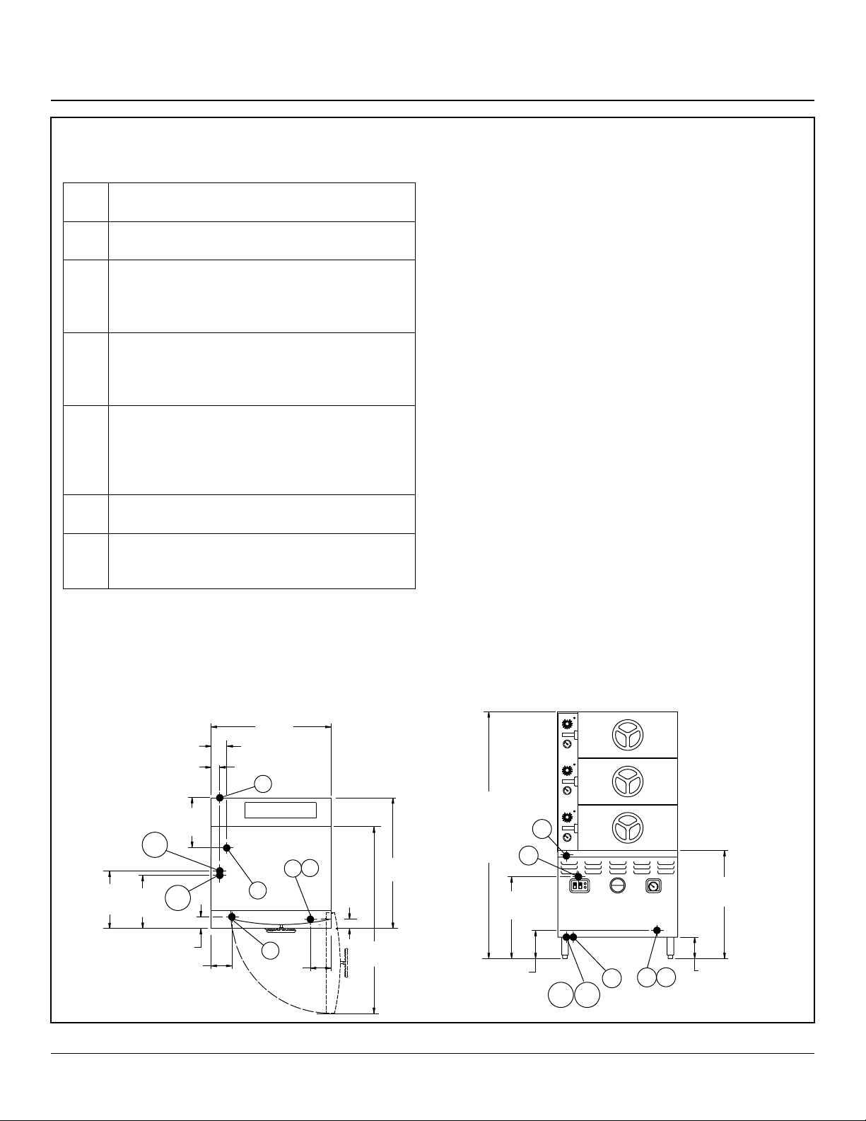
2AM36G & 3AM36G
SERVICE CONNECTIONS
G Gas Connection - 3/4” (19mm) N.P.T. female for
200,000 BTU boiler.
G1 Gas Connection - 1” (25mm) N.P.T. female for
300,000 BTU boiler.
CW1 Cold Water - 3/8” (10mm) NPT for cold water to
boiler. Cold water lines will have a maximum of
50 PSI (3.5kg/cw2) and a minimum of 25 PSI
(1.8 kg/cw2) water pressure.
CW2 Cold Water - 3/8” (10mm) NPT for cold water to
condenser. Cold water lines will have a maximum of 50 PSI (3.5kg/cw2) and a minimum of
25 PSI (1.8 kg/cw2) water pressure.
D Drain - Pipe full 2” (50mm) NPT to ush oor
drain capable of receiving water owing at a
maximum rate of 5 gallons (19 liters) per minute. DO NOT MAKE SOLID CONNECTION TO
FLOOR DRAIN.
EC Electrical Connection - 120 Volts AC, 60 Hz, single
phase, and a 9 foot Power Cord/NEMA 5-15.
ST Steam Take-off - Connection for operations of
adjacent steam powered equipment. Requires
steam take-off kit (optional at extra cost).
DIMENSIONS ARE IN INCHES [MM]
OPERATION WILL BE BY
Gas red, A.S.M.E. constructed and National Board Reg-
2
istered, 15 PSI (1 kg/cm
) steam boiler rated at 200,000
BTU
Notes: If equipment is installed where elevation exceeds
2,000 feet (609.6 meters) above sea level, specify instal-
lation altitude so that proper gas orices can be provided.
The only available space to supply utilities to the gas
boiler is the 6” (152mm) space between the oor and the
cabinet.
Allow 3” (76mm) space from side wall and 6” (152mm)
from rear wall if adjoining walls are combustible.
PVC & CPVC PIPE ARE NOT ACCEPTABLE MATERIALS FOR DRAINS.
CAUTION: REMOTE KETTLE OPERATION If this boiler
is feeding a remote kettle that will be more than 5 feet
(1.5 meters) away, consult factory before ordering.
WATER SUPPLY
Good quality water feed is the responsibility of the owner.
Water quality must be within the following general guide-
lines.
TDS: 40-125 ppm Chlorides: <25 ppm
Silica: <13 ppm pH: 7.0 - 8.5
Chloramine: <0.2 ppm Chlorine: <0.2 ppm
Hardness: 35-100 ppm
The best defense against poor water quality is a water
treatment system designed to meet your water quality
conditions.
CW1
12.5
10.5
[318
[267]
INSTALLATION
4[102]
2.5 [64]
10.5
[267]
CW2
3 [76]
5 [127]
36 [914]
EC
FLUE
D
ST
5 [127]
68 [1730]
3AM36G
22
[559]
8 [203]
ST
EC
28
[711]
6 [152]
G1
G
D
CW1CW2
55 [1397]
G1
G
2.75
[70]
33
[838]
53
[1346]
2AM36G
Figure 1
2
Page 5
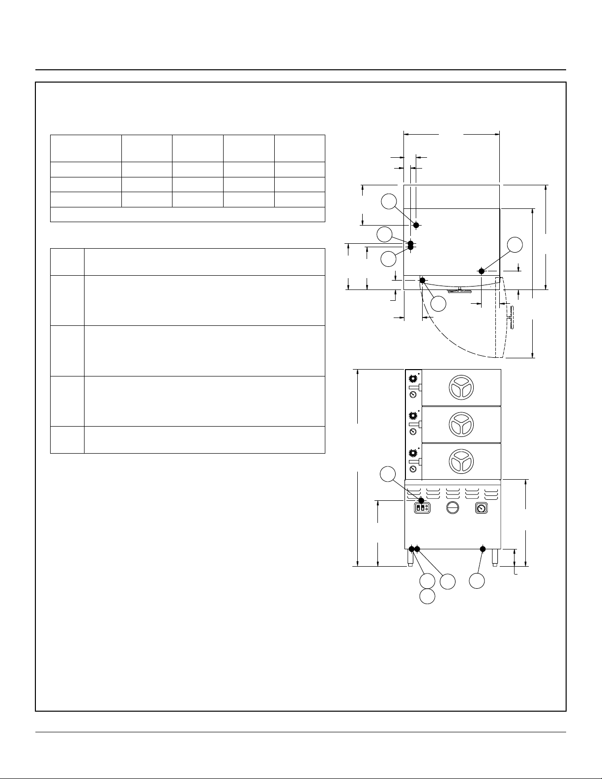
2AM36E & 3AM36E
Service Connections
ELECTRICAL REQUIREMENTS
24kW
3pH
36kW
3pH
42kW
3pH
48kW
3pH
208 (197-219) 66 100 117 --
240 (220-240) 58 87 -- 116
480 (360-500) 29 44 -- 58
Details of other electrical systems available upon request.
SERVICE CONNECTIONS
EP Power Supply - Use wire suitable for at least 90°C.
Nominal amp per line wire:
CW1 Cold Water - 3/8” (10mm) NPT for cold water to boil-
er. Cold water lines will have a maximum of 50 PSI
(3.5kg/cw2) and a minimum of 25 PSI (1.8 kg/cw2)
water pressure
CW2 Cold Water - 3/8” (10mm) NPT for cold water to con-
denser. Cold water lines will have a maximum of 50
PSI (3.5kg/cw2) and a minimum of 25 PSI (1.8 kg/
cw2) water pressure.
D Drain - Pipe full 2” (50mm) NPT to ush oor drain ca-
pable of receiving water owing at a maximum rate of
5 gallons (19 liters) per minute. DO NOT MAKE SOLID CONNECTION TO FLOOR DRAIN.
ST Steam Take-off - Connection for operation of adjacent
steam powered equipment.
OPERATION WILL BE BY:
Electrically powered, A.S.M.E. constructed and National Board
Registered, 15 PSI (1 kg/cm2) steam boiler rated at
24kW
NOTE: The only available space to supply utilities to the boiler is
the 6” (152mm) space between the oor and the cabinet base.
PVC & CPVC Pipe are not acceptable materials for drains.
CAUTION: REMOTE KETTLE OPERATION If this boiler is feeding a remote kettle that will be more than 5 feet (1.5 meters)
away, consult factory before ordering.
WATER SUPPLY
Good quality water feed is the responsibility of the owner. Water
quality must be within the following general guidelines.
DIMENSIONS ARE IN INCHES [MM]
4 [102]
2.5 [64]
10.5
[267]
12.5
[318]
68 [1730]
3AM36E
55 [1397]
2AM26E
10.5
[267]
D
CW1
CW2
3 [76]
5 [127]
ST
22
[559]
CW1
CW2
36 [914]
ST
D
6 [152]
EP
[152]
EP
33
[838]
6
56
[1346]
28
[711]
6 [152]
TDS: 40-125 ppm Hardness: 35-100 ppm Chlorine: <0.2 ppm
Silica: <13 ppm Chlorides: <25 ppm
Chloramine: <0.2 ppm pH: 7.0 - 8.5
The best defense against poor water quality is a water treatment
system designed to meet your water quality conditions.
Figure 2
3
INSTALLATION
Page 6
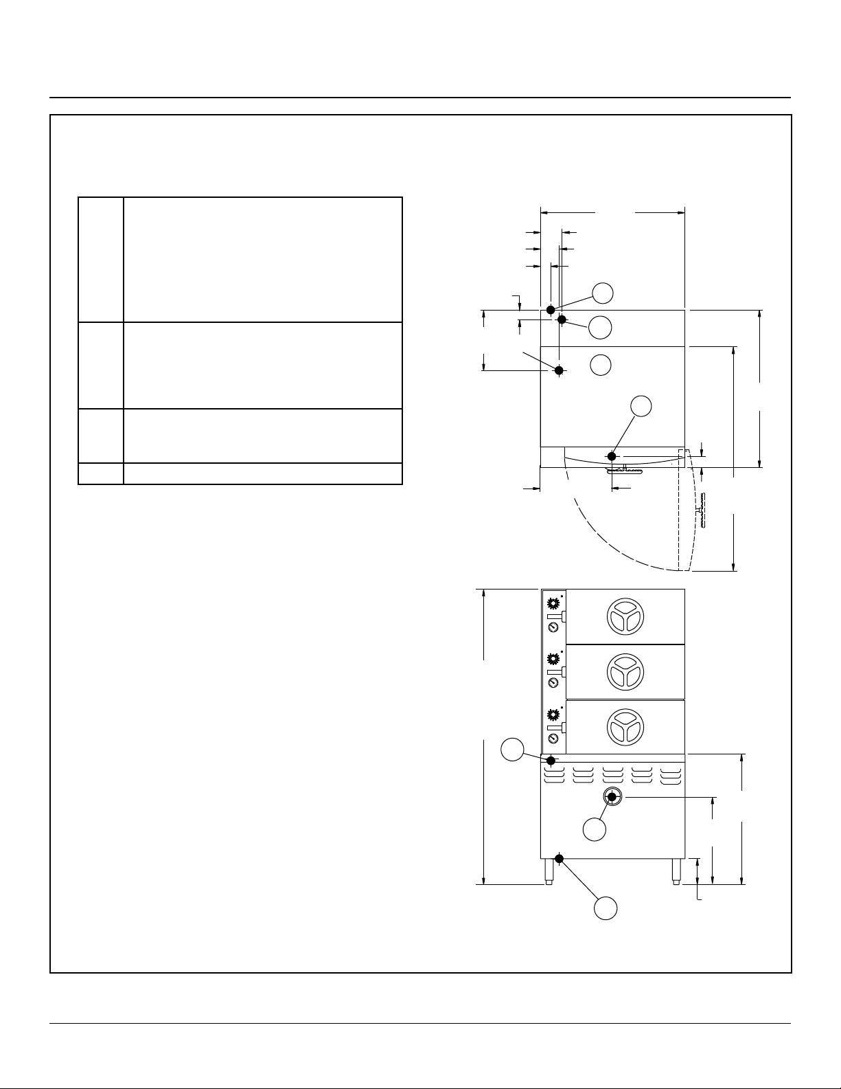
Service Connections
2AM36D & 3AM36D
SERVICE CONNECTIONS
S Steam Supply: 3/4” (19mm) NPT Shall have
a minimum incoming pressure of 15 PSI.
Pressure reducing valve will reduce incom-
ing pressure (up to 200 PSI) to required 5
PSI (0.4kg/cm2).
NOTE: Steam supply must be food grade
quality.
D Drain - Pipe full 1” (25mm) NPT to ush oor
drain capable of receiving water owing at
a maximum rate of 5 gallons (19 liters) per
minute. DO NOT MAKE SOLID CONNECTION TO FLOOR DRAIN.
EC Electrical Connection - 120 Volts AC, 60 Hz,
single phase, and a 9 foot Power Cord/
NEMA 5-15.
CR Condensate Return - Optional
NOTES: Allow 12” (305mm) spacing on left and 6”
(152mm) spacing on right if height of adjoining wall or
equipment exceeds 29” (737mm).
PVC and CPVC pipe are not acceptable materials for
drains.
DIMENSIONS ARE IN INCHES [MM]
4.3 [109]
4 [102]
2.5 [64]
2 [51]
10.5
[267]
17 [432]
36 [914]
EC
CR
D
33
S
3 [76]
[838]
53
[1346]
WATER SUPPLY
Good quality water feed is the responsibility of the owner. Water
quality must be within the following general guidelines.
TDS: 40-125 ppm Chlorides: <25 ppm
Silica: <13 ppm pH: 7.0 - 8.5
Chloramine: <0.2 ppm Chlorine: <0.2 ppm
Hardness: 35-100 ppm
The best defense against poor water quality is a water treatment
system designed to meet your water quality conditions.
Appliance to be installed with backflow protection according to
federal, state or local codes.
Figure 3
68 [1730]
3AM36D
55 [1397]
2AM26D
EC
28
[711]
S
D
17
[432]
6 [152]
INSTALLATION
4
Page 7

2A & 3A
Service Connections
SERVICE CONNECTIONS
S Steam Supply - 3/4” (19mm) NPT Shall have a
minimum incoming pressure of 15 PSI (1kg/
cm2). Pressure reducing valve will reduce in-
coming pressure (up to 200 PSI) to required
5 PSI (0.4kg/cm2). NOTE: STEAM SUPPLY
MUST BE FOOD GRADE QUALITY.
D Drain - Pipe full 1” (25mm) NPT to ush oor
drain capable of receiving water owing at a
maximum rate of 5 gallons (19 liters) per minute. DO NOT MAKE SOLID CONNECTION TO
FLOOR DRAIN.
EC Electrical Connection - 120 Volts AC, 60 Hz,
single phase, and a 9 foot Power Cord/NEMA
5-15.
NOTES: Allow 12” (305mm) spacing on left and 6”
(152mm) spacing on right if height of adjoining wall or
equipment exceeds 29” (737mm).
PVC and CPVC pipe are not acceptable materials for
drains.
One BHP is required per compartment.
WATER SUPPLY
Good quality water feed is the responsibility of the owner. Water
quality must be within the following general guidelines.
TDS: 40-125 ppm Chlorides: <25 ppm
Silica: <13 ppm pH: 7.0 - 8.5
Chloramine: <0.2 ppm Chlorine: <0.2 ppm
Hardness: 35-100 ppm
The best defense against poor water quality is a water treatment
system designed to meet your water quality conditions.
Appliance to be installed with backflow protection according to
federal, state or local codes.
DIMENSIONS ARE IN INCHES [MM]
6
7
[178]
Hold down flanges
from center line of leg
4 [102]
[152]
S
7.5 [191]
1.5 [38]
1.5 [38]
must be bolted
down within a
1-5/16” [33] Ø
2 [51]
EC
D
3 [76]
EC
D
34.5 [876]
32.5 [826]
1/2” [13] Ø 2 holes
for 3/8” [10] bolt
8
[203]
20.25
[514]
55 [1400] - 2A
58 [1480] - 3A
30 [762]
53 [1346]
Figure 4
5
28 [711] - 2A
18 [457] - 3A
S
20 [508] - 2A
10 [254] - 3A
22 [559] - 2A
12 [304] - 3A
INSTALLATION
Page 8

PRV – Pressure Reducing Valve Maintenance and Adjustments
WATTS PRESSURE REDUCING VALVE –
MARKET FORGE PART NUMBER 10 - 1033
To provide adequate steam pressure regulation, your
cooker / steamer may be equipped with a Watts Pressure
Reducing Valve ( PRV ). The ¾” PRV is designed to regulate an incoming Maximum pressure of 200 PSI down to
Operating pressures between 5 – 20 PSI. The PRV will
safely regulate the incoming steam to your type of unit.
The chart below indicates the required Incoming Pressure
for the following Market Forge Models.
Model Max. Operation
Pressure
A - cooker 5 PSI 200 PSI
Max. Incoming
Pressure
ADJUSTING WATTS ¾” PRESSURE REDUCING
VALVE
1. Release the locking wing nut (Item 1) and loosen the
adjusting screw spring (Item 2)
2. Turn the inlet steam supply to full open. Then turn
adjusting screw (Item 2) clockwise just enough to allow the valve to open slightly. Allow cooker / steamer
to operate in this manner for several minutes by pulling out the steam operating handle or turning on the
timer.
3. Turn adjusting screw (Item 2) down slowly at intervals
until reduced pressure reaches the desired set-point
per the chart below.
4. Tighten locking wing nut (Item 1)
5. If a chattering noise should occur, move adjusting lever or screw (Item 3 as shown) located in bottom half
of the valve body, clockwise or counter-clockwise, until chattering stops.
2
1
3
Figure 5
INSTALLATION
6
Page 9

Preheating
MODEL A COMPARTMENT STEAM COOKER:
1. Be sure that steam pressure is at the unit.
a. Direct Steam - Turn on external steam supply
valve.
b. All other Units - Follow steam boiler operating in-
structions on control box cover plate inside cabinet base.
c. Be sure that 115 volt connection has been made
to the unit.
PREHEATING-MANUAL CONTROLS:
1. Close compartment door engaging both door latches.
If door does not latch, turn door wheel counterclockwise until both latches are engaged.
2. Seal cooking compartment door by turning door
wheel clockwise until wheel is hand tight.
CAUTION
Do not wrench door wheel tight. This action
can cause needless damage to both the door
wheel and door gasket over a period of time.
3. Start preheating by pulling steam control lever out
and down.
NOTE: Always start one compartment at a time.
Each compartment has an individual steam
control and is operated independently.
4. Pull steam control lever out and down.
5. Compartment timer will sound to end preheating.
6. Release steam control valve by lifting lever.
7. Allow time for steam and condensate to leave the
compartment before opening the door.
8. Allow pressure to return to 0 PSI. Loosen door by
turning wheel counter clockwise. Push primary door
latch from door lip. Allow remaining steam to dissipate from the partially open door. Then lift secondary
latch, and open the door fully.
PREHEATING-AUTOMATIC CONTROLS:
1. Close compartment door engaging both door latches.
If door does not latch, turn door wheel counterclockwise until both latches are engaged.
2. Seal cooking compartment door by turning door
wheel clockwise until wheel is hand tight.
CAUTION
Do not wrench door wheel tight. This action
can cause needless damage to both the door
wheel and door gasket over a period of time.
3. Place automatic override switch in AUTO (down position).
4. When pressure gauge indicates a minimum of 3 PSI,
set timer at 5 minutes by going beyond 15 minutes
and back to 5 minutes for accurate timing.
5. Pull the operating handle out and down and allow it
to lock in this position. Pilot light next to the timer will
come on indicating that unit is operating.
6. The sound of the buzzer indicates the end of cycle
and that steam and condensate are being exhausted. Steam control lever will release automatically.
Time indicates 0 minutes.
7. Turn off buzzer by setting timer to OFF position from
0 minute setting.
8. Allow time for all steam and condensate to leave the
compartment before opening the door.
NOTE: If AUTOMATIC CONTROLS fail, place auto-
matic override switch in MANUAL (up position) and time all procedures manually.
9. Allow pressure to return to 0 PSI. Loosen door by
turning wheel counter-counter-clockwise. Push primary door latch from door lip. Allow remaining steam
to dissipate from the partially open door. Then lift secondary latch, and open the door fully.
7
OPERATION
Page 10

Basic Operating Instructions
BASIC OPERATING INSTRUCTIONS FOR AUTOMATIC CONTROLS:
1. Check to be sure the steam pressure gauge registers
between 4 and 5 pounds.
2. Place pans of food into the cooking compartment to
be used.
3. Close and latch the door.
4. Turning the door wheel clockwise to seal the cooking
compartment.
WARNING
Do not permit steam to leak. Set the door tight
enough to make a rm seal. Steam leakage
will cause undue wear to the gasket.
5. Turn timer pointed clockwise to the 60 minute mark,
and then to the desired cooking time.
6. Pull the operating handle out and down and allow it
to lock in this position. Pilot light next to the timer will
come on indicating that unit is operating.
7. The pilot light will signify this cooking compartment
is in operation. At the end of the cooking cycle the
AUTOMATIC controls will release the operating handle, shutting off the steam supply and exhausting the
steam from the cooking compartment. The pilot light
will turn off and the buzzer will signify that cooking
has been terminated.
BASIC OPERATING INSTRUCTIONS FOR MANUAL
CONTROLS:
1. Check to be sure the steam pressure gauge registers
between 4 and 5 pounds.
2. Place pans of food into the cooking compartment to
be used.
3. Close and latch the door.
4. Turning the door wheel clockwise to seal the cooking
compartment.
WARNING
Do not permit steam to leak. Set the door tight
enough to make a rm seal. Steam leakage
will cause undue wear to the gasket.
5. Pull the operating handle out and down and allow it to
lock in this position.
6. Turn timer pointed clockwise to the 60 minute mark,
and then to the desired cooking time.
7. Set timer. When bell rings, lift handle and push in to
shut off cooker.
8. To silence the buzzer, turn the TIMER KNOB to the
OFF position.
OPERATION
8
Page 11

Cooking Tips
HELPFUL HINTS
1. Always preheat compartments for satisfactory operation.
2. When all compartments are to be used at once, let
steam into each compartment separately (after food
is loaded) allowing pressure for one compartment to
recover to 3 pounds before letting steam into the next
compartment.
3. Should steam seep out and around compartment
door, check to see that the door wheel is adequately
hand tightened. If, after tightening the door wheel,
steam continues to seep around the door, the door
gasket should be replaced. It is a good procedure to
keep an extra door gasket on hand for this purpose.
4. If greasy foods have been cooked in the compartment steam cooker, steam should be passed through
the lines after the cooking period to help remove any
fat that might remain in the line. To do this, follow
the same procedure as preheating (Steps 3-8 under
PREHEATING-MANUAL CONTROLS).
5. To prolong gasket life, leave compartment doors
slightly ajar when unit is not in use. Under no circumstances, however, should all compartment doors be
left wide open at the same time.
6. Keep compartment door wheels free and easy to
turn by periodically removing inner door and applying
small amounts of door lubricant to acme type screw.
Be sure inner threads are also lubricated by turning
wheel a number of times. To remove, open door, turn
door wheel clockwise as far as possible, then lift inner
door up and pull out.
6. Food may be served from the same pan in which it
is steam cooked, thus reducing food breakage since
there is no extra handling or transferring of food from
cooking pan to serving pans. It also reduces pot
washing tasks.
7. Some important advantages of steam cooking are:
reduce fuel costs, decrease food cost, cut cooking
and clean up time, cook more food in less space and
increase employee productivity.
8. Rice and spaghetti products, if thoroughly wet at the
start of the cooking process are very easily prepared.
9. Foods such as potatoes, poultry, seafood and some
meats may be blanched in the steam cooker, thus reducing the total cooking time and grease absorption.
10. Fuel is used only when the steam cooking unit is in
operation.
11. The steam cooker will loosen foods burned on pans
making washing easier.
12. Solid pans are recommended when liquid is to be re-
tained and perforated pans when the liquid is not to
be retained.
13. Eggs may be cooked out of the shell if they are to be
chopped which eliminates peeling after steaming.
14. Frozen or stale bread may be readied for serving with
a small amount of steam.
15. The steam cooker can be opened during the cooking
period (by rst releasing the steam pressure) to add
or remove items. If any time is lost, an adjustment
may be made on the timer.
A COOKER FACTS ON PARADE
1. Many foods, except those requiring dry heat can be
cooked in a steam cooking unit.
2. Steam cooked foods have a greater nutritional value since more of their vitamins and minerals are retained.
3. Because foods are cooked faster by the higher temperatures of steam cooking, they can be prepared
closer to serving time, insuring maximum freshness.
4. Steam cooked food has a higher percent yield - more
portions per dollar spent.
5. The principle upon which the steam cooker is based
can be likened to the domestic pressure cooker.
16. All frozen foods must be thoroughly defrosted in order
to obtain the most satisfactory results.
17. Steam cooking information, including recommended
pan sizes and type, weight per pan, cooking times
and pan yields are given on the following pages of
this bulletin.
9
OPERATION
Page 12

Suggested Steam Times
The steam cooker compartment is a pressure cooker which operates at 5 PSI (0.33kg/cm2). This enables the cook to prepare foods nearer to the time of service. The gures given below are timer settings and should be set on a pre-heated compartment either with manual or automatic controls. If a large or cold load is put in, it will be necessary to set the timers after
a minimum of three pounds pressure shows on the compartment steam gauge. On the manual units the timer will sound
and the steam must be manually exhauster, where as it is automatically exhausted on the others, thus stopping the cooking
cycle. Six 12” x 20” x 21/2” or Four 12” x 20” x 4” pans may be used in each compartment. Suggested pan sizes for various
foods are give below and on the next two pages.
FROZEN VEGETABLES, DEFROSTED
Six 12” x 20” x 21/2” pans of thoroughly defrosted vegetables may be done at once. For uniform results, it is recommended
that not more than 5# (2.3kg) of frozen vegetables be evenly distributed in a 12” x 20” x 21/2” perforated pan. Loosen pack
peas, corn and diced carrots may be cooked, once package per 12” x 20” x 21/2” pan, in the frozen state if time does not
allow for defrosting.
WEIGHT
ITEM
Asparagus, Spears
Beans,Green Regular
Beans,Green French Cut
Beans,Lima
Broccoli
Brussel Sprouts
Carrots,Diced
Caliower
Corn
Peas
* All portions are equivalent to approximately
PER PAN
5#
(2.3kg)
5#
(2.3kg)
5#
(2.3kg)
5#
(2.3kg)
6#
(2.7kg)
5#
(2.3kg)
5#
(2.3kg)
5#
(2.3kg)
5#
(2.3kg)
5#
(2.3kg)
SIZE OF PAN
PERFORATED
12” x 20” x 21/2”
12” x 20” x 21/2”
12” x 20” x 21/2”
12” x 20” x 21/2”
12” x 20” x 21/2”
12” x 20” x 21/2”
12” x 20” x 21/2”
12” x 20” x 21/2”
12” x 20” x 21/2”
12” x 20” x 21/2”
1
/2 cup cooked.
NUMBER
OF PANS
1-3
4-8
1-3
4-8
1-3
4-8
1-3
4-8
1-3
4-8
1-3
4-8
1-3
4-8
1-3
4-8
1-3
4-8
1-3
4-8
TIMER
SETTINGS IN
MINUTES
10-12
13-15
10-12
13-15
10-12
13-15
10-12
13-15
8-10
10-12
10-12
13-15
9-10
11-13
11-12
13-15
9-10
11-13
6-7
8-9
NO. OF COOKED
PORTIONS PER PAN*
3 oz. (65g)
23-25
23-25
23-25
23-25
18-20
23-25
23-25
23-25
23-25
23-25
VEGETABLES, CANNED
WEIGHT
ITEM
Canned, Vegetables
* All portions are equivalent to approximately
PER PAN
71/2 #
(3.4kg)
OPERATION
SIZE OF PAN
PERFORATED
12” x 20” x 21/2”
1
/2 cup cooked.
10
NUMBER
OF PANS
1-3
4-8
TIMER
SETTINGS IN
MINUTES
4-5
5-8
NO. OF COOKED
PORTIONS PER PAN*
3 oz. (65g)
26-30
Page 13

VEGETABLES, FRESH
Suggested Steam Times
WEIGHT
ITEM
Green Beans, Wax
Broccoli, 1/2” - 3/4” , Stalks
Cabbage , Cored - 1/4
1/6 of Head
Carrots, Sliced
Cauliower
Con on the Cob, Husked 1 Doz. 12” x 20” x 21/2”
Potatoes, French Fry Cut
Potatoes, Regular Cut
Spinach, Cut and Cleaned
Squash, Summer,
1” Slices
Squash, Winter, Diced
Turnip, Diced
* All portions are equivalent to approximately
PER PAN
6#
(2.7kg)
6#
(2.7kg)
5#
(2.3kg)
9#
(4kg)
6#
(2.7kg)
10#
(4.5kg)
10#
(4.5kg)
3#
(1.4kg)
7#
(3.2kg)
9#
(4kg)
5#
(2.3kg)
SIZE OF PAN
PERFORATED
12” x 20” x 21/2”
12” x 20” x 21/2”
12” x 20” x 21/2”
12” x 20” x 21/2”
12” x 20” x 21/2”
12” x 20” x 21/2”
12” x 20” x 21/2”
12” x 20” x 4”
12” x 20” x 21/2”
12” x 20” x 21/2”
12” x 20” x 21/2”
1
/2 cup cooked.
NUMBER
OF PANS
1-3
4-8
1-3
4-8
1-3
4-8
1-3
4-8
1-3
4-8
1-3
4-8
1-3
4-8
1-3
4-8
1-2
3-4
1-3
4-8
1-3
4-8
1-3
4-8
TIMER
SETTINGS IN
MINUTES
15-20
20-25
10-15
15-20
14-16
16-20
18-21
21-25
10-15
15-20
10-12
12-15
15-18
18-20
25-30
30-35
3-5
4-8
8-12
12-15
15-20
20-25
25-30
30-35
NO. OF COOKED
PORTIONS PER PAN*
3 oz. (65g)
30-35
25-30
12-20
25-40
30-35
12
50
50
10-12
30-35
30-35
20-25
MISCELLANEOUS
WEIGHT
ITEM
Eggs, in Shell
Eggs, out of Shell
Rice, 1 Gallon of Water 4# 12” x 20” x 4”
Spagetti, 1
* All portions are equivalent to approximately 1/2 cup cooked.
1
/2 - 2 Gallons Water 3# 12” x 20” x 4”
PER PAN
3 doz.
4 doz.
SIZE OF PAN
SOLID
12” x 20” x 21/2”
PERFORATED
12” x 20” x 21/2”
11
NUMBER
OF PANS
1-3
4-8
1-3
4-8
1-2
3-4
1-2
3-4
TIMER
SETTINGS IN
MINUTES
8-9
9-10
6-7
7-8
22-24
25-27
20-22
23-26
NO. OF COOKED
PORTIONS PER PAN*
2 oz. (55g)
36
48
60
3 oz. (85g) Portions
40-45
4 oz. (110g) Portions
OPERATION
Page 14

Suggested Steam Times
MEAT - POULTRY - FISH
WEIGHT
ITEM
Chicken, Cut Up, Blanched
Chicken, Whole
Fish, Fillets
Fowl %# or More, Whole
Fankforts
Hamburgers, 3 ounce
Meatballs, ** 1 Ounce
Meatloaf **
Pork Chops, Loin,
4 Ounces with Bone 6#
Sausages, 10 Per Pound
Turkey, on Carcass
Turkey, off Carcass
* All portions are equivalent to approximately
PER PAN
8#
(3.6kg)
three 4#
(1.8kg)
3#
(1.4kg)
two 5#
(2.3kg)
5#
(2.3kg)
5#
(2.3kg)
6#
(2.7kg)
15#
(6.8kg)
6#
20-22#
10-12#
SIZE OF PAN
SOLID
12” x 20” x 21/2”
12” x 20” x 4”
12” x 20” x 21/2”
12” x 20” x 4”
12” x 20” x 21/2”
PERFORATED
12” x 20” x 21/2”
12” x 20” x 21/2”
12” x 20” x 21/2”
12” x 20” x 21/2”
12” x 20” x 21/2”
12” x 20” x 4”
12” x 20” x 21/2”
1
/2 cup cooked.
NUMBER
OF PANS
1-3
4-6
1-2
3-4
1-3
4-6
1-2
3-4
1-3
4-6
1-3
4-6
1-3
4-6
1-3
4-6
1-3
4-6
1-3
4-6
1-2 100-120
1-3
4-6
SETTINGS IN
MINUTES
TIMER
18-25
25-30
45-55
55-65
8-12
10-15
50-65
60-75
3-4
4-5
12-14
15-18
18-22
22-25
40-45
45-50
25-30
30-35
18-21
22-25
50-60
60-75
NO. OF COOKED
PORTIONS PER PAN*
3 oz. (65g)
15-20
Protein
25-30
Protein
12-15
Protein
20-25
Protein
35-40
Protein
20-25
Protein
20-25
Protein
50-60
Protein
24
Protein
18-20
Protein
50-60
Protein
55-65
Protein
** Raw weight for meatballs and meatloaf includes hamburg and extenders and yields 2 ounces protein plus extenders, or
3 ounces total portion.
OPERATION
12
Page 15

Preventative Maintenance
CAUTION
DO NOT HOSE DOWN UNIT AS IT CONTAINS ELECTRICAL COMPONENTS.
GENERAL
This section contains both preventive and corrective maintenance information required for the A Cooker. Preventive maintenance may be performed by maintenance personnel at the establishment in which the cooker is installed. It is recommended
that user personnel never attempt to make repairs or replacements to the equipment without the assistance of authorized
service. Assistance in service methods or a current Directory of Authorized Service Agencies may be obtained from Market
Forge.
PREVENTIVE MAINTENANCE
A good preventive maintenance program begins with the daily cleaning procedure described in the table below. Additional
preventive maintenance operations are presented in this section.
FREQUENCY PROCEDURE
DAILY 1. CLEANING: Remove pan supports, shelves and shelf supports, and thoroughly wash and rinse
interior of both cooking compartments. Be sure the drain screen, located inside top compartment,
is clear of all food particles.
WEEKLY 1. SAFETY VALVE CHECK: With upper compartment in operation in the pressure cooking mode, lift
up on level of forward mounted safety valve. Repeat for rear mounted safety valve. Steam should
ow freely from outlet port, verifying proper functioning and clearing of accumulated deposits in
valves.
2. INNER DOOR CLEANING: Remove inner door from both compartments. Wash inner door and
inside of outer door with mild detergent, rinse and reassemble.
MONTHLY 1. DOOR WHEEL LUBRICATION: Check door hand wheel rotation for ease of motion. If wheel resists
rotation when door is unlatched, lubrication is required. Remove inner door and apply graphite lubrication to screw threads.
DRAIN SCREEN CLEANING & REMOVAL
The drain screen inside the top compartment is provided
to prevent blockage of the drain line. It must be kept clean
at all times by scrubbing daily with a stiff bristle brush.
WARNING
A plugged drain may cause compartment
ooding, resulting in overow of scalding
water when door is opened.
Should the drain screen require removal due to excessive
blockage or damage, the truss head screw is loosened
and the screen slipped out. The screen must be in position, completely covering the lower drain opening, prior to
reuse of the A Cooker.
SAFETY VALVE CHECK
The safety valves are protective devices which automatically relieve excessive pressure (above 8 PSI) in the un-
likely event of equipment malfunction. Manual opening of
the valves is also possible and should be done once a
week to assure valves are clear and mechanically sound.
1. Place upper cooker compartment into operation in
the pressure mode and allow pressure to build to
about 4 PSI.
2. Pull up on safety valve lever for forward-mounted
valve (closest to manifold box on left side of cooker).
Flow of steam from the valve outlet veries correct
manual valve function and clears exhaust passage.
NOTE: Steam is not present at relief valve until steam
trap has evacuated all air from the cooker
compartment. Presence of adequate steam
should be checked (4-5 psi on gauge) before
checking valve.
3. Repeat step 2 for rear-mounted valve.
13
MAINTENANCE
Page 16

Preventative Maintenance
INNER DOOR REMOVAL & CLEANING
The door assembly includes an outer door with mounted
hand wheel and an inner door with sealing gasket. The inner door parts should be cleaned weekly to ensure proper
sealing against compartment opening.
1. With door opened and hand wheel turned to full
clockwise position, grasp tabs and lift inner door up
and away from door.
Wash inner doors, gaskets and inside of outer door with
mild detergent, rinse and reassemble.
DOOR WHEEL LUBRICATION
The door wheel includes the externally mounted wheel
and built-in screw mechanism. Rotation of the door wheel
should be checked monthly for ease of motion. If the
wheel grinds or is difcult to turn, the screw should be
lubricated with graphite followed by rotation of the wheel
to transfer lubricant into threads in door.
REPLACING WORN OR DAMAGED DOOR GASKET
Remove the screws from the gasket of the inner door. Slip
out the old gasket. Clean the face of the inner door and
the gasket plate. Place the new gasket and gasket plate
in position and fasten the screws through the assembly
as illustrated below. Tighten the screws enough to make
a rm seal. It is recommended that a spare gasket be kept
on hand in event of an emergency. Replacement gaskets
may be obtained for your model by requesting MODEL
“A” DOOR GASKET #10-0433. Include the serial number
of your steam cooker with your order when ordering parts.
Figure 6
MAINTENANCE
14
Page 17

Door Assembly Instructions
1. Make sure the handle on the door is turned as far
clockwise as possible.
Figure 7
2. Take the inner door out of cavity. Remove packaging
and discard.
3. Line up the outer door pins (marked “A”) with the inner door holes (marked “B”). Set the door in place
and turn handle counter-clockwise until you bring the
inner door to the outer door.
Figure 9
Figure 8
15
MAINTENANCE
 Loading...