

Market Forge 2800 Service Manual
MODULAR ELECTRIC CONVECTION OVEN
AREA CODE
617 387
-
4100
MODEL NUMBERS 2600, 2800
STYLE A & B
PARTS & SERVICE MANUAL
TABLE OF CONTENTS
Subject Code No. Page
OPERATING INSTRUCTIONS 5194 2
EXPLODED VIEW & PARTS LIST 5195 3
HEATING ELEMENTS ASSEMBLY & PARTS LIST 5196 4
SERVICING THE CONTROL PANEL 5197 5
SERVICING INNER OVEN COMPONENTS 5197 5
SERVICING CONVECTION FAN & THERMOSTAT 5185 6
CONTROL PANEL VIEW 5199 7
CONTROL PANEL COMPONENTS 81 BLOWER GUARD
STACKED ELECTRIC OVENS 5201 9
OVEN DOOR VIEW - STYLE A 5190 10
OVEN DOOR VIEW - STYLE B 5191 11
OVEN DOOR INSTRUCTIONS 5192 12
WIRING DIAGRAM (C-99-1694) 5202 13
WIRING DIAGRAM (C-99-3050) 5203 14
WIRING DIAGRAM (C-99-1693) 5204 15
WIRING DIAGRAM (B -99-3036) 5205 16
WIRING DIAGRAM (C-99-3036) 5206 17
5200 8
Printed in U.S.A.
Rev 12/79
5198

OPERATING INSTRUCTIONS
Do not attempt to operate ovens without first reading the following instructions thoroughly:
1. Be sure that power is available to the unit.
2. Be sure that both the blower quard and deflector are properly mounted.
3. Snap on "Power On" switch with doors open.
4. Arranqe shelf positions dependent upon item to be baked or roasted. Refer to cooking chart on right panel of
oven and to Recipe Cards for correct positioning.
5. Close doors. Blower should come on and rotate clockwise, otherwise unit is not operating correctly. If blower
does not start or starts and immediately stops, this may indicate an electrical overload. Reset circuit breaker
on control panel. If blower still does not operate, this is an indication of incorrect wiring or other electrical
problems. Have your electrician check the wiring if this is an initial operation, otherwise call your dealer from
whom this equipment was purchased.
6. Preheat to temperature and allow to cycle once to obtain even temperature throughout oven. Total time,
approximately 15 minutes.
7. Oven is ready to cook and may be loaded when indicator light goes off. The load should be adjacent to the
oven to facilitate rapid loading so that doors will be open as short a time as possible.
8. If using the convection oven for long term roasting of meats, fish or poultry, place about a quart of water in a
suitable container in the oven or under a trivet in the same pan as the meat.
9. Close doors and set timer for desired cooking time.
10. Interior lights may be turned on or off as desired. If lights fail to operate reset circuit breaker on control panel.
If lights still fail to operate this indicates faulty bulbs. If lights still fail to operate this indicates an internal
electrical fault and an electrician should be notified.
11. Bell will ring when cooking is completed. Oven is ready to unload.
12. If oven temperature is to be lowered, set thermostat to the desired temperature. Keep the blower operating
by leaving right door closed and left door open.
When indicator light comes ON, oven is at lower temperature. Close both doors. When indicat or light goes off
— oven is ready to use.
13. When oven is to be turned off, turn oven thermostat to off — turn power switch to off. Leave doors ajar.
NOTE: Fan should always operate in a clockwise rotation.
2

ELECTRIC OVENS
1 Top Panel
………………………………………
99-
1570
99-
1569
Socket Ass'y……………………………………
31 Thermostat Guard
……………………………
99-
3039
99-
3039
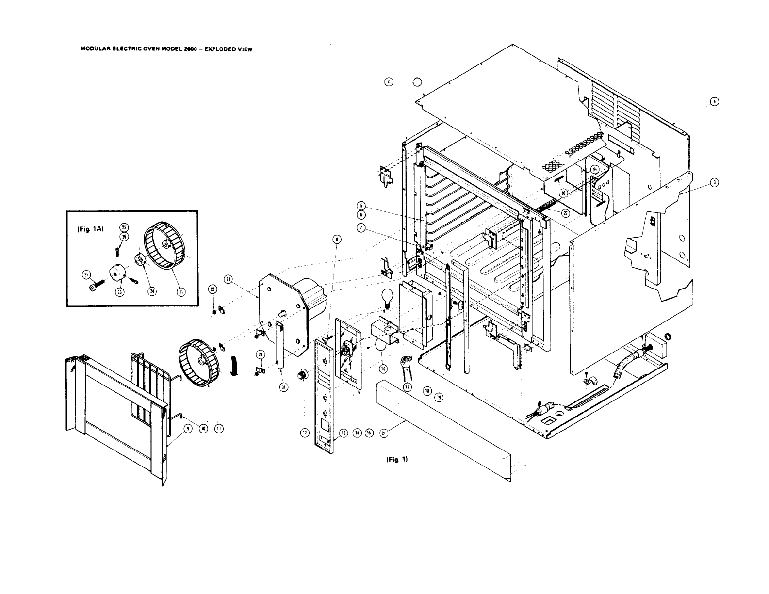
MASTER ILLUSTRATION - Parts List
Item No Description Standard Deep
2 L H Panel Ass'y……………………………… 99-1574 99 1578
3 R H Panel Ass'y……………………………… 99-1576 99-1580
4 Rear Panel …………………………………… 99-1572 99-1572
5 LH Rack Support …………………………… 10 1295 10-1296
6 RH Rack Support …………………………… 10-1295 10-1296
7 Clip ……………………………………………… 99-1925 99-1925
8 Wing Screw …………………………………… 10-1988 10-1988
9 Deflector Ass'y ……………………………… 99-0959 99-0959
10 Fan Guard ……………………………………… 10-5957 10-5957
11 Blower Wheel ………………………………… 10-5453 10-5453
12 Knob …………………………………………… 10-4472 10-4472
13 Control Panel Ass'y…………………………… 99-3049 99-3049
14 Thermostat …………………………………… 10-4714 10-4714
15 Glass Ass'y …………………………………… 99-3026 99-3026
16 Light Bulb ……………………………………… 10-5148 10-5148
17
18 Insulation ……………………………………… 99-3052 99-3052
19 Door Switch …………………………………… 10-6209 106209
20 Motor Ass'y 60Hz 115/230V ……………… 99-0665 99-0665
Motor Assy - 50 Hz 110/220V……………… 99-0675 99-0675
Motor Assy - 60 Hz 460 V…………………… 99-0676 99-0676
21 Bottom Panel Ass'y…………………………… 99-3035 99-3035
22 1/2"-13 Allen Soc Hd Cap Screw ………… 10-1984 10-1984
23 Wheel Puller …………………………………… 99-3333 99-3333
24 Collar (Use with Small Hub) ………………… 99-3332 99-3332
25 5/16"-18 Allen Soc Hd Cap Screw ………… 10-1985 10-1985
26 5/16"-24 Allen Soc Hd Cap Screw ………… 10-1986 10-1986
27 Capillary Tube Guard ………………………… 99-3040 99-3040
28 Clip ……………………………………………… 99-0951 99-0951
29 Hex Nut - 5/16-18 ……………………………… 10-2335 10-2335
30 5/16-18 Hex Head Cap Screw 2-1/4" Lg…… 10-2117 102117
10-5149 10-5149
3a 5195
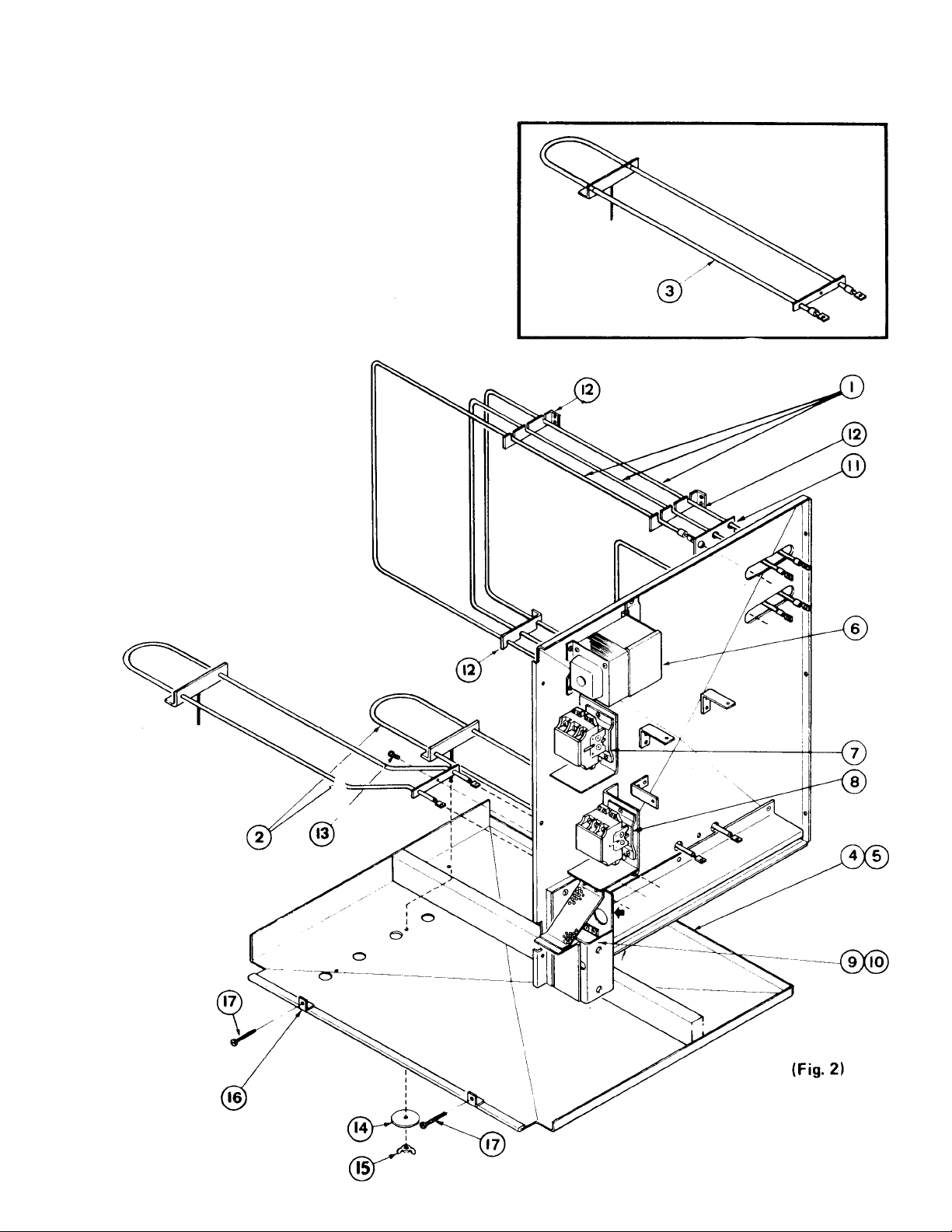
MODULAR ELECTRIC OVEN MODEL 2600 - HEATING ELEMENTS
4

ELECTRIC OVEN HEATING ELEMENTS - Parts List
INSIDE OVEN LINER STYLE B
Item No. Description Part No.
1 Heating Elements, Standard Oven, 3100 Watts, 208 V 10-6084
Heating Elements, Standard Oven, 3100 Watts, 230 V 10-6085
2 Heating Elements, Standard Oven, 1400 Watts, 208 V 10-6650
Heating Elements, Standard Oven, 3100 Watts, 440/479 V 10-6086
Heating Elements, Standard Oven, 3100 Watts, 480 V 10-6087
Heating Elements, Deep Oven, 4000 Watts, 208 V 10-6678
Heating Elements, Deep Oven, 4000 Watts, 230 V 10-6843
Heating Elements, Deep Oven, 4000 Watts, 440/479 V 10-6844
Heating Elements, Deep Oven, 4000 Watts, 480 V 10-6845
BELOW OVEN LINER STYLE B
Heating Elements, Standard Oven, 1400 Watts, 230 V 10-6651
Heating Elements, Standard Oven, 1400 Watts, 440/479 V 10-6652
Heating Elements, Standard Oven, 1400 Watts, 480 V 10-6653
Heating Elements, Deep Oven, 1800 Watts, 208 V 10-6677
Heating Elements, Deep Oven, 1800 Watts, 230 V 10-6684
Heating Elements, Deep Oven, 1800 Watts, 440/479 V 10-6685
Heating Elements, Deep Oven, 1800 Watts, 480 V 10-6686
BOTTOM ELEMENTS STYLE A
3 Heating Elements, St'd. and Deep Ovens, 1400 Watts, 208 V 10-6527
4 Retaining Shield Ass'y. - Standard 99-3055
5 Retaining Shield Ass'y. - Deep 99-3043
6 Transformer, 440-480 V 10-5396
7 Contactor, 208 V 10-5466
8 Contactor, 230 V, 440-480 V 10-5467
9 Terminal Block, 440-480 V. Units Only 10-5503
10 Circuit Breaker, 208/230 V. 70 Amps 10-6520
11 Insulation 99-1882
12 Bracket - 208/230 V 99-1653
13 # 8 Sheet Metal Screw 10-1735
14 Washer 99-1789
15 Wing Nut, #8-32 10-2382
16 Weld Bracket, # 8-32 10-2356
17 Pan Head Slotted Machine Screw # 8-32 x 1-5/8" Lg. 10-1954
Heating Elements, St'd. and Deep Ovens, 1400 Watts, 230 V 10-6528
Heating Elements, St'd. and Deep Ovens, 1400 Watts, 440/479 V
Heating Elements, St'd. and Deep Ovens, 1400 Watts, 480 V 10-6530
Bracket - 440/480 V 99-1820
4a 5196
10-6529

SERVICING THE CONTROL PANEL
5 5197
1. Remove 6 screws from control panel (Fig.
1) (13). All controls on the control panel are
serviceable from the front.
WARNING
Be sure that the entire power supply is
disconnected before removing front control
panel to avoid accidental shorting.
REPLACEMENT OF CONTACTORS,
TRANSFORMERS OR CIRCUIT BREAKERS
1. Remove (4) screws from top panel (Fig. 1)
(1) on right hand side of oven and 4 screws
from rear panel (4).
2. Remove (6) screws from control panel (13).
3. Remove right side panel (3) to gain access
to controls.
2. Unscrew two screws and remove brackets
(12) on bottom of heating elements (1) on right
and left hand side of oven liner.
3. Slide heating element (1) out. Remove two
screws from heating element terminal end
holding wire to element.
4. Replace with new element (1) and install in
reverse sequence of above.
REPLACING BOTTOM HEATING ELEMENTS
1. Drop bottom front panel of oven (Fig. 1) (21).
2. Remove wing nut (Fig. 2) (15) and washer
(14) from retaining panel inside of oven liner.
Remove two screws (17) from front of oven liner.
3. Lower retaining panel (4) (5). Remove screw
(13) from insulated bracket of heating elements
(2).
4. Replace defective part and reassemble.
Note: Transformer only present on 440-480 V
units and foreign.
REPLACING REAR HEATING ELEMENTS
1. Unscrew three screws and remove
insulated bracket (Fig. 2) (11) on top rear right
hand corner of inside of oven liner.
4. Slide heating element (2) out. Remove
two screws from heating element terminal end
holding wire to element.
5. Replace new element (2) and install in
reverse sequence of above.

CHANGING FAN
1. To remove fan (Fig. 1A) (11), obtain wheel
puller (Part No. 99-3334) from Market Forge.
2. Remove baffle (9) and fan guard (10). Place
wheel puller over hub of fan (11). Tighten
set screws on wheel puller into hub.
3. Gradually tighten hex bolt on front of wheel
puller until fan slides out from shaft.
REMOVING FAN MOTOR
6. Slip thermostat bulb (14) out from clips
and through hole in side of oven.
7. Slide entire assembly out through front of
oven through the control area.
TO CALIBRATE THERMOSTAT
1. Be sure thermocouple is installed in clips
provided in the oven.
2. Attach your thermocouple lead to the
bulb of the thermostat (14).
1. Remove baffle (Fig. 1) (9) and fan guard (10).
2. Unscrew four hex nuts (29) from studs
(30). Disconnect wiring connected to fan
motor (20). Refer to wiring diagram B-99-
1 790. Motor is pulled forward off studs (30).
3. When remounting motor (20) be sure it is
mounted in the same position and that
deflector assembly is installed as outlined
below.
INSTALLING DEFLECTOR ASSEMBLY
Deflector assembly (Fig. 1) (9) should be installed
so it is equidistant in all directions (north, south,
east, west). If adjustment is required, use adjustment clips (28) located on fan motor assembly.
TO REPLACE THERMOSTAT
1. Remove six screws from top panel (Fig. 1) (1)
on right hand side of oven and four screws
from rear panel (4).
2. Remove six screws from control panel (13).
3. Remove right side panel (3).
4. Remove guard (31) that covers thermostat
bulb (14) secured to fan motor housing
inside oven liner.
5. Remove five screws that secure perforated
capillary tube guard (27) to oven liner.
3. With the line switch in the "on" position, set
the thermostat control switch to 400° F and
carefully remove the switch control knob.
4. Allow the unit to heat until the pilot light
goes out.
5. Adjust the thermostat setting (using a fine
blade screw driver in the stem of the
thermostat).
6. With the oven temperature set at 400°F
the cycling should retain a peak of 420°F
and a low of 380°F after two stabilizing
cycles. A good indication of proper calibration is the time when the heating
elements or burners cut off and cut in and
should be:
Example: Cut off 400°F to 405°F
Cut in 380°F to 385°F
7. After calibration has been complete, apply
Duco cement to the adjusting screw of the
thermostat switch and replace the knob.
IMPORTANT: If it is found that the
thermostat is our of calibration by 50°F or
more, the thermostat should be replaced
not calibrated.
6 5185
 Loading...