

Page 1
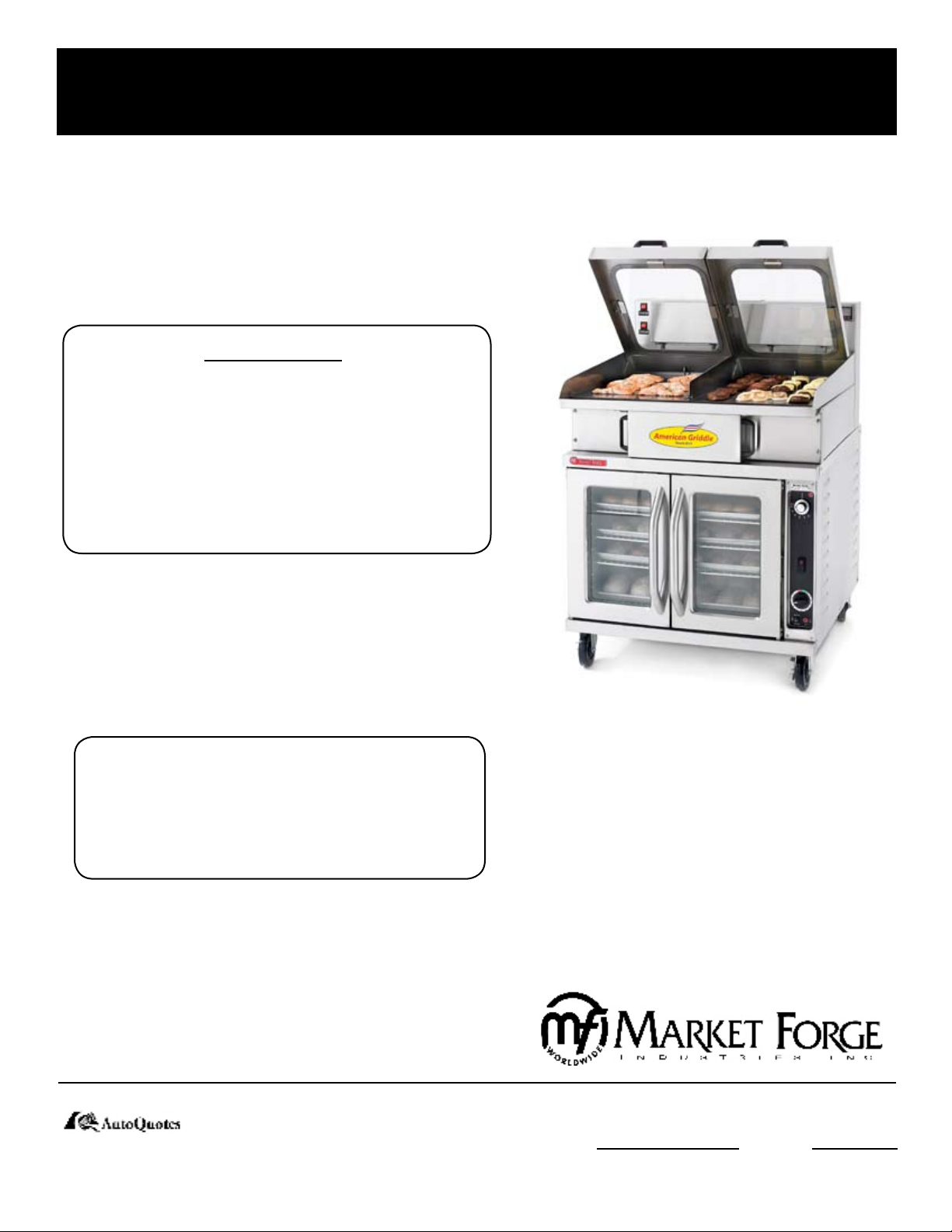
ELECTRIC PURR-FECT HEIGHT STEAM SHELL
GRIDDLE CONVECTION OVEN COMBO
OWNER’S MANUAL
WARNING:
NEVER MAKE ANY REPAIRS
OR ADJUSTMENTS TO THE
GRIDDLE/OVEN WHEN HOT
OR IN OPERATION. THIS CAN
RESULT IN SERIOUS INJURY.
MODELS:
STEAM PRESSURE MUST BE
REDUCED TO 0 PSI BEFORE
ATTEMPTING REPAIRS!
Form Number: S-6040 12/06
Printed in U.S.A. 35 Garvey Street l Everett l MA l 02149
Fax: (617) 387-4456 l Outside MA Fax: (800) 227-2659
E-Mail: CUSTSERV@mi.com l Website: www.mi.com
2624 (without Steam)
•
2624S (with Steam)
•
2636 (without Steam)
•
2636S (with Steam)
•
An Employee Owned Company
Tel: (617) 387-4100 l Toll Free: (888) 698-3188
Page 2

TABLE OF CONTENTS
2624, 2624S, 2636, 2636S GRIDDLE
INTRODUCTION 1
INSTALLATION 1
GENERAL 1
CLEARANCES 1
WATER CONNECTION 1
ELECTRICAL CONNECTION 2
ELECTRICAL SPECIFICATION AND PLUG TYPES 2
GRIDDLE SPECIFICATIONS 2
FILLING THE BOILER WITH WATER 3
TURN OFF WATER SUPPLY 3
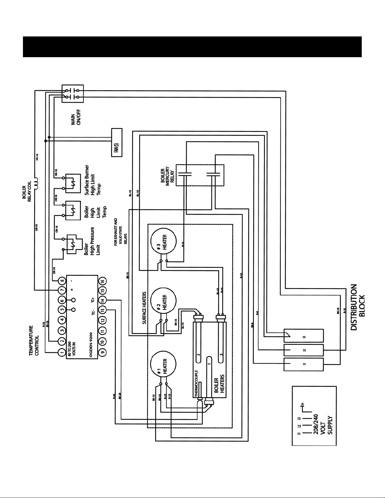
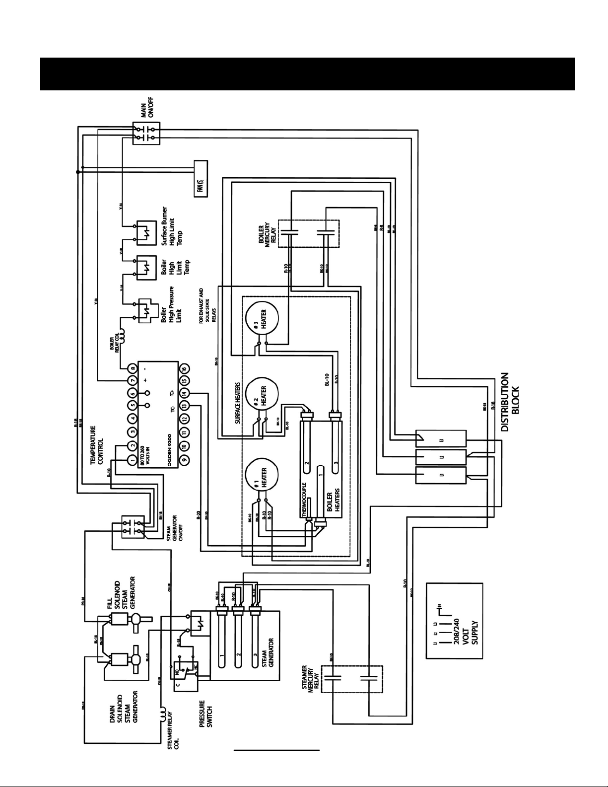
WIRING DIAGRAM 4
OPERATION 6
SETTING THE GRIDDLE 6
GRIDDLE SHUT DOWN PROCEDURE FOR UN-HEATED STORAGE 6
HOT TO SET TEMPERATURE 6
GRIDDLE CLEANING AND SEASONING 7
GRIDDLE COOKING GUIDE AND TIMES 8
TROUBLE-SHOOTING 9
CLEANING / PREVENTIVE MAINTENANCE 10
DE-SCALING STEAM GENERATOR 10
ILLUSTRATIONS 11
APPENDIX 22
2600PHE OVEN
YOUR ENERGY EFFICIENT CONVECTION OVEN 23
HOW THE OVEN OPERATES 23
OPERATING CONTROLS AND INDICATORS 24
CLEANING / PREVENTIVE MAINTENANCE 25
TROUBLE-SHOOTING 25
ILLUSTRATED PARTS 26
APPENDIX 33
i
Page 3
2624, 2624S, 2636, 2636S Griddle
INTRODUCTION
The high performance Market Forge Purr-fect Height Steam Shell Griddle Convection Oven Combo creates a new class of
steam cooking equipment. More heat is delivered per square inch than any other griddle and assures food safety. Additionally, steam is injected into the cooking compartments. This technology allows the food to be cooked from both sides, dramatically decreasing cooking times and allowing for broader menu items. These items include seafood, stir-fry, vegetables
and pork. With the glass window in the cooking lids, food can be observed while cooking.
INSTALLATION
GENERAL: Once the unit is installed it must be elec-
trically grounded and comply with local codes, or in the
absence of codes with the National Electrical Code ANSI
NFPA 70-1999. Installation in Canada must comply with
CSA Standard C22. NO. 109-M1987.
CLEARANCES: Allow at least a three in clearance between the back of the unit and any wall obstruction for
proper ventilation, room for plumbing and electrical connections. The ventilation opening on the back of the griddle must have access to cool air. Griddle needs to be placed
on a level surface to provided ultimate performance. A nonlevel unit could lead to heating element damage.
THIS PROCEDURES SHOULD BE FOLLOWED BY
QUALIFIED PERSONNEL ONLY. DAMAGE WILL
VOID WARRANTY!
All griddles are shipped with a de-scaling filter. Installing
the de-scaling filter according to the manufacturers instructions. See manual included with de-scaler. If de-scaler filter
is not included with the griddle when shipped, contact the
factory. Failure to use approved de-scaler system may void
warranty.
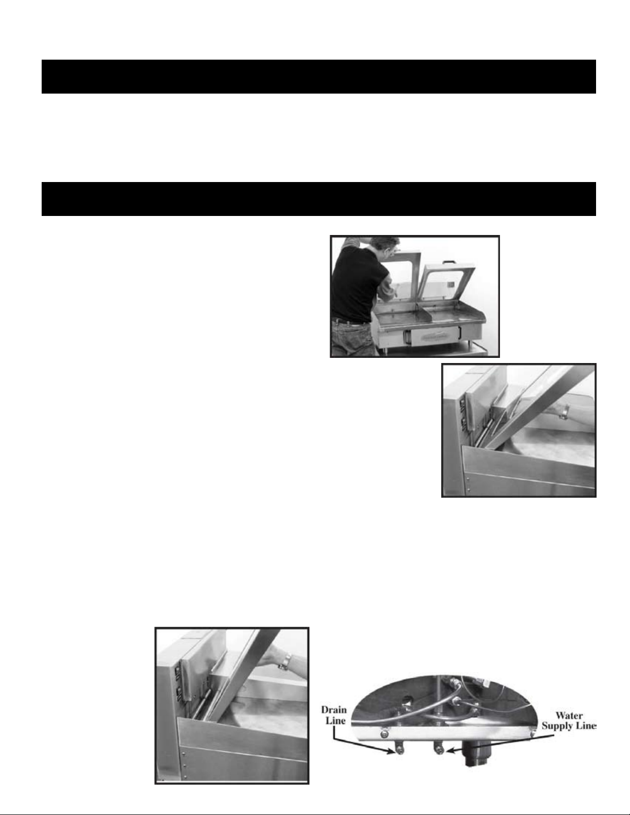
TO INSTALL:
Unpack carefully. Remember to report any damage to
1.
the freight company immediately.
Do not remove any tags or labels until the unit is in-
2.
stalled and working properly.
Set the unit on a level floor.
3.
Install lids as shown in figures 1 through 3.
4.
CAUTION:
Glass Doors!
Use extra caution
when unpacking.
Figure 1
Lift lid with both
hands and set para llel to back of unit.
Figure 2
Figure 3
Once lid is securely
seated under counterweight bar, lower lid
slowly parallel to surface
of griddle.
WATER CONNECTION:
Connect to cold waterline, 1/4” tubing. DO NOT CONNECT
TO HOT WATER SOURCE! Waterline pressure should be
30 PSI minimum. Recommended 1/4” stainless steel braided
hose for water supply line. Dp not use transparent water tubing. Connect 1/4” tubing to drain fitting and run to drain location.
A water de-scaling filter system must be installed to comply
with warranty. If you do not have your own water de-scaling
and filter system contact our factory immediately.
Slide lid until lift flange
on lid is under counterweight bar.
1
Page 4
2624, 2624S, 2636, 2636S Griddle
INSTALLATION
ELECTRICAL CONNECTIONS:
Electrical supply to unit must conform to the National Electrical Codes. See appliance nameplate for service requirements.
For proper connection of field wiring to junction box, see the wiring diagram on page 4-53. Make sure the input voltage
and phase match the requirements shown on the serial plate. (The serial plate is located on the rear of the grill cabinet.)
NOTE: Depending on the model of the griddle it may require two power sources. DO NOT ALLOW ANY TAMPERING
OR ADJUSTMENT OF ANY CONTROL OR WIRING. THE UNIT IS FACTORY SET AND ADJUSTMENT OF ANY
INTERNAL COMPONENT OTHER THAN THE JUNCTION BOX CAN VOID WARRANTY.
ELECTRICAL SPECIFICATION AND PLUG TYPES
MODEL VOLTS PH TOTAL
AMP
2’ 208/240 3 45 60 (3) 2500WATT (3) 3500 WATT-BOILER HEATERS
HZ STEAMER HEATERS @
16.8 AMPS
BOILER & SURFACE HEATERS
@ 29 AMPS
(3) 1500 WATT-SURFACE HEATERS
STEAMER HEATERS @
18 AMPS
3’ 208/240 3 58 60 (3) 3500 WATT (3) 3500 WATT-BOILER HEATERS
STEAMER HEATERS @
18 AMPS
4’ 208/240 3 85 60 (3) 4500 WATT (3) 3500 WATT-BOILER HEATERS
BOILER & SURFACE HEATERS
@ 40 AMPS
(3) 1500 WATT-SURFACE HEATERS
BOILER & SURFACE HEATERS
@ 40 AMPS
(3) 1500 WATT-SURFACE HEATERS
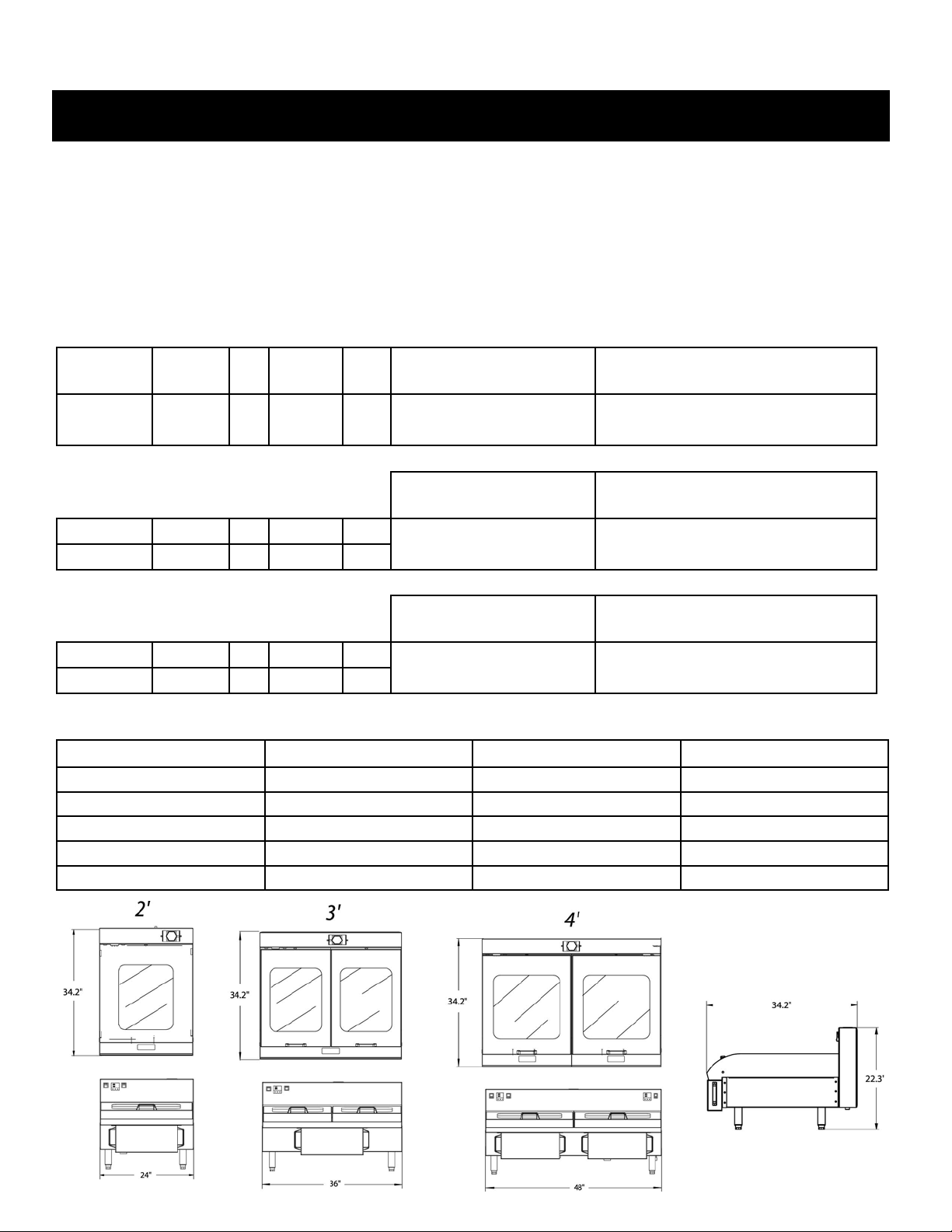
GRIDDLE SPECIFICATIONS
2’ 2’ 4’
Griddle Surface 23.8” Wide x 26.5” Deep 35.8” Wide x 26.5” Deep 47.8” Wide x 26.5” Deep
Cooking Compartments 1 1 2
Temperature Zone 1 1 2
Exterior Dimensions 24” W x 34.2” D x 22.3” H 36” W x 34.2” D x 22.3” H 48” W x 34.2” D x 22.3” H
Max Operating Temperature 390oF 390oF 390oF
2
Page 5
2624, 2624S, 2636, 2636S Griddle
INSTALLATION
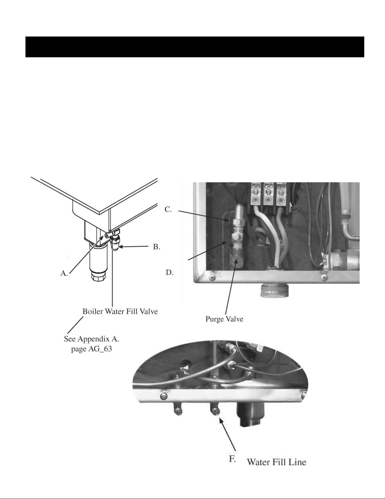
FILLING BOILER WITH WATER:
CAUTION: MAKE SURE POWER IS OFF AND GRIDDLE IS COOL.
TURN OFF WATER SUPPLY:
Locate boiler water fill valve located front right of the griddle and remove caps (A & B). Locate purge valve
left back of griddle inside power head and remove caps (C & D). Detach existing water fill hose rear of
unit (F) and attach to boiler water fill located front right of griddle (A). Open valve; allow water to run until
water exits purge valve then close purge valve. Close fill valve. Turn water line at its source and disconnect.
Replace caps on all fittings.
3
Page 6
2624, 2624S, 2636, 2636S Griddle
INSTALLATION
4
Page 7
2624, 2624S, 2636, 2636S Griddle
INSTALLATION
5
Page 8
2624, 2624S, 2636, 2636S Griddle
OPERATION
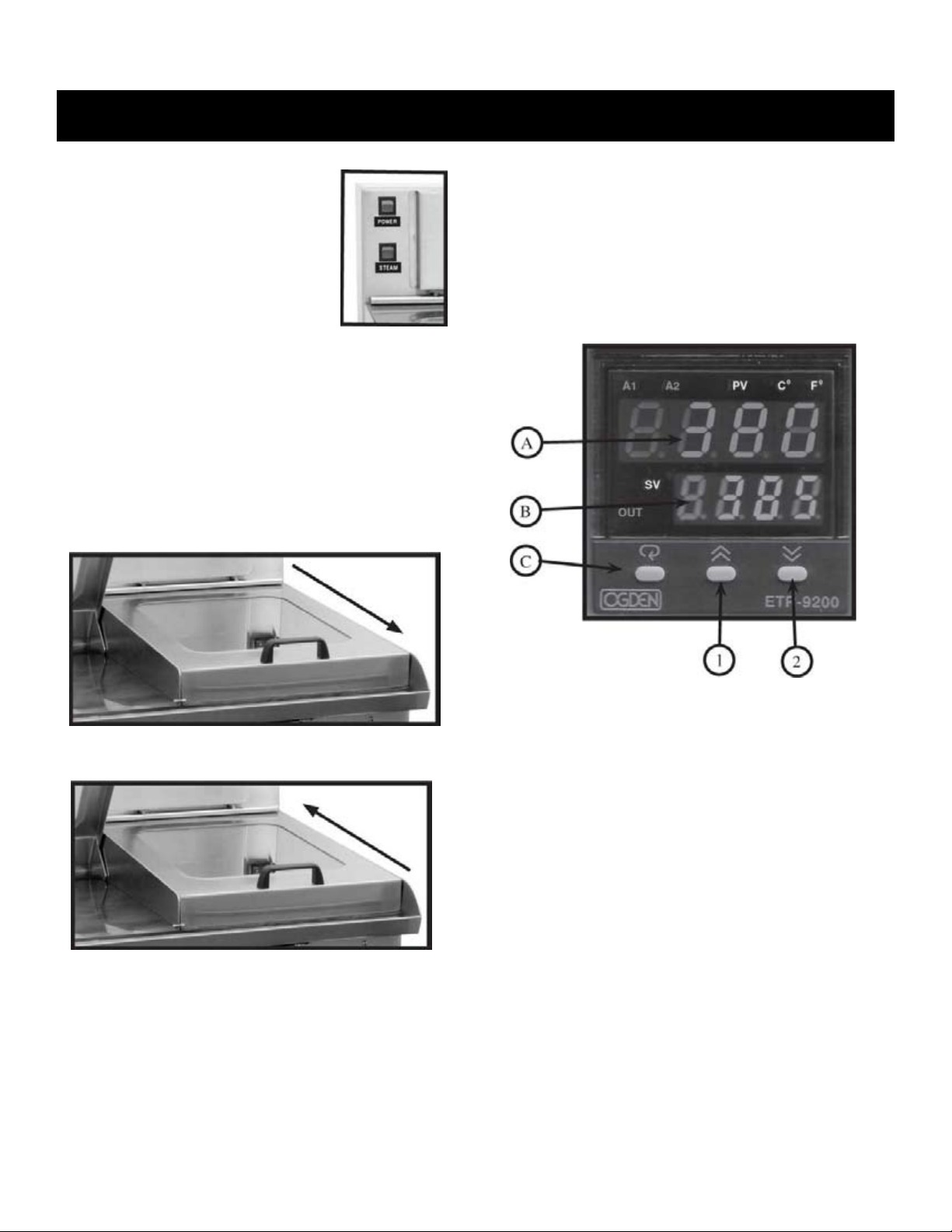
STARTING THE GRIDDLE:
1. Turn on the main power switch for the
griddle.
a. Main power switch.
b. Power switch on the steam
generator.
2. Set control to the desired temperature.
(265oF minimum to cook, heating period is 20 mins.)
3. Allow griddle to reach set point temperature before
beginning to cook. Heating period is 20 mins.
STARTING AUTOMATIC STEAM INJECTION LIDS
WHEN COOKING:
NOTE: Steam injection will not turn on unless lid is lowered
to closed position and pushed towards back of griddle.
Slightly lifting lid and pulling forward will turn off steam.
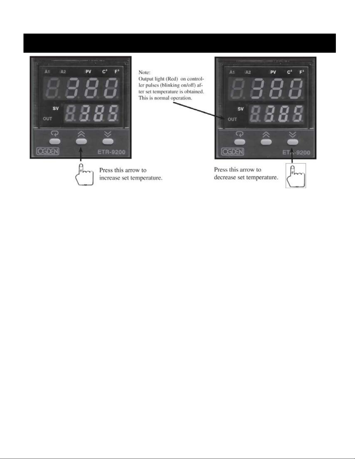
HOW TO SET TEMPERATURE:
A. Actual temperature reading.
B. Desired set temperature.
C. Factory set program function.
1. Increase desired set temperature.
2. Decrease desired set temperature.
Pushing lid back will turn steam back on.
GRIDDLE SHUT DOWN PROCEDURE FOR UNHEATED STORAGE:
1. Disconnect water and electrical supply.
2. Water will need to be drained and blown out with com pressed air from all components. It is recommended that
a qualified service agent do this.
OGDEN CONTROLLER 9200
Tap button 1 or 2 (up or down key) for less than 1 sec-
•
ond.
All four temperature digits on the lower display will light
•
with the first digit being brighter.
Advance to the digit you want to change by pressing but-
•
ton 1 or 2 (up or down key) for less than 1 second.
To change the value of the digit hold in the up or down
•
key. After 10 seconds the new value will be entered and
the display will read normally.
Tap either arrow button once to highlight all digits.
•
Once desired digit is highlighted hold the proper button
•
in to increase or decrease digits.
Refer to page 6 for illustrated help.
6
Page 9
2624, 2624S, 2636, 2636S Griddle
OPERATION
GRIDDLE CLEANING AND SEASONING:
1. Seasoning is a process to protect the griddle from rusting and prevent foods from sticking to the surface
during cooking.
2. Use only a small amount of vegetable oil, such as Wesson. Spread is around evenly (avoiding Corners)
while heating.
3. Pour salt over griddle surface and rub in circular motions over entire griddle surface with a handle and
grill screen.
4. When the oil begins to smoke, turn off griddle and squeegee off salt and oil. Let griddle cool for a 30
minute period.
5. Repeat the process one of two more times.
6. Re-season as needed.
7. Do not use water, soaps or griddle cleaners to clean griddle surface. If you do, you must re-season griddle
surface. In between normal cooking operation scrape griddle with a plastic scraper to keep clean. DO
NOT THROW COLD WATER ON A HOT GRIDDLE! it may cause the griddle surface to warp.
7
Page 10

TYPE PRODUCT PORTIONS MINUTES
Beef Hamburger 4 oz. 3-4
Beef Hamburger 6 oz. 5-6
Beef Hamburger 8 oz. 6-8
Beef Hamburger 12 oz. 9
Poultry Chicken Breast 4 oz. 4
Poultry Chicken Breast 5 oz. 5
Poultry Chicken Breast 6 oz. 6
Poultry Thighs 6 oz. 6
Poultry Quarters 10 oz. 20
Poultry Quarters Marinated 10 oz. 16-18
Seafood Crab Legs 1 lb. 12
Seafood Lobster 6 oz 6
Seafood Shrimp 16/20 1 oz 1 1/2
Seafood Snow Crab 1 lb. 8-9
Seafood Scallops - Cape 4 oz 3
Seafood Crab Cakes 4 oz 4
Seafood Crab Stuffed Mushrooms 6 oz 6
Fish Haddock 4-5 oz. 3-4
Fish Yellow Fin Tuna 5 oz. 4
Fish Salmon 8 oz. 4-5
Fish Cod 4 oz. 4
Eggs Fried 2 Each Under 1
Eggs Omelet 3 Eggs Under 1
Eggs Scrambled 2 Each Under 1
Breads Grilled BLT 7-8 oz. 5
Breads Grilled Cheese 4.5 oz. 2
Breads Reuben Sandwich 7-8 oz. 4
Breads Tortilla 20” 20
Breads Potato Pancakes 4 oz. 4
Breads French Toast 2-3 oz. 3
Breads Pattie Melt 4 oz. 4
Breads Quesadillas 12” Under 1
Sausages Patties / Thick 2 oz. 5
Sausages Patties / Thin 1/4” 2 oz. 3
Sausages Links 1 oz. 6-8
Sausages Brats 4 oz. 7
Sausages Hot Dog 5/1 6
Sausages Polish 4 oz. 6
Sausages Italian Rope 16 oz. 7 1/2
GRIDDLE COOKING GUIDE AND TIMES
Vegetables Broccoli Florets 16 oz. 6-7
Vegetables Asparagus 11 oz. 5-6
Vegetables Mushrooms, Large Whole 16 oz. 6-7
Vegetables Mushrooms, Sliced 16 oz. 3
Vegetables Peppers & Onions 1/2” Cut 24 oz. 3
Vegetables Carrots 16 oz. 6-7
Vegetables Corn 16 oz. 5
Pork Chop Center Cut 6 oz. 6
Pork BBQ Rib Slab 6 or less
Pork Cutlet 4 oz. 4
Lamb Chops / Thick 3/4” 1 1/2-2 oz. 4
8
Page 11

2624, 2624S, 2636, 2636S Griddle
TROUBLE-SHOOTING
The griddle is designed to operate smoothly and efficently is properly maintained. However, the following is
a list of checks to make in the event of a problem.
Wiring diagrams are furnished inside the service panel as well as in this manual.
IF AN ITEM ON THE LIST IS FOLLOWED BY AN (*), THE WORK SHOULD BE DONE BY A QUALIFIED SERVICE AGENT.
PROBLEM PROBABLE CAUSE REMEDY
LOW WATER IN BOILER 1. Steam system leak. 1. Repair leak.*
HEATER(S) NOT WORKING Unit not wired properly.
GRIDDLE HOTTER THEN SET POINT Temperature controller out of cali-
GRIDDLE HEATS UP TOO SLOWLY Heater(s) not working.
GRIDDLE NOT HEATING UP Temperature control not set high
UNEVEN SURFACE TEMPERATURE Air in system.
NO POWER Power switch off.
NO STEAM COMES OUT OF NOZZLE Start up procedure not done.
STEAM GENERATOR WATER LOW Water supply to steam generator off.
NOT ENOUGH STEAM PRESSURE Heater(s) not working.
HEATER(S) NOT WORKING Wired incorrectly.
1.
Heater(s) bad.
2.
Contactor or solid state relays not
3.
working.
Failed temperature controller.
4.
1.
bration.
Thermocouple sensor defective.
2.
Solid stare relay(s) stuck on.
3.
Failed temperature controller.
4.
1.
Too much water in boiler.
2.
1.
enough.
Low water in boiler.
2.
Failed temperature controller.
3.
Heater(s) not working.
4.
1.
Low water in boiler.
2.
1.
Not plugged in.
2.
Breaker off or tripped.
3.
1.
Steam generator low on water.
2.
Lid not closed.
3.
Heater(s) not working.
4.
Steam solenoid defective.
5.
1.
Water solenoid plugged or defective.
2.
1.
Pressure switch out of adjustment or
2.
defective.
Pressure switch waterlogged.
3.
1.
Heater(s) bad.
2.
Pressure switch out of adjustment or
3.
defective.
Pressure switch waterlogged.
4.
Check wiring.*
1.
Replace heater(s).*
2.
Repair or replace.*
3.
Replace temperature controller.*
4.
Recalibrate temperature controller.*
1.
Replace thermocouple.*
2.
Replace solid state relay(s).*
3.
Replace temperature controller.*
4.
Purge air per instruction.
1.
Remove excess water.
2.
Adjust to desired temperature.
1.
See ”low water in boiler”.
2.
Replace temperature controller.*
3.
See “heater(s) not working”.
4.
Check water level and purge air from
1.
system. Check for leaks.
Check water level in boiler. Add
2.
water if needed.
Turn on power switch.
1.
Check plug.
2.
Check breaker.
3.
Check for shorts.*
4.
Perform “start up procedure”.
1.
See “steam generator water low”/
2.
Lid must be closed to activate steam.
3.
See “heater(s) not working”.
4.
Replace.
5.
Check water supply.
1.
Repair or replace.*
2.
See “heater(s) not working”.
1.
Repair or replace.*
2.
Restore air trap for pressure switch
3.
and repair air leak.
Check wiring.*
1.
Replace heater(s).*
2.
Repair or replace.*
3.
Restore air trap for pressure switch
4.
and repair air leak.
9
Page 12

2624, 2624S, 2636, 2636S Griddle
CLEANING / PREVENTIVE MAINTENANCE
Cleaning procedures for griddle and stainless steel surfaces:
1. Suggested tools: Rubber Squeegee, rubber or plastic
scrapers, plastic wool, cloth, griddle cleaner and sanitizer.
2. Precautions: Before any cleaning, reduce temperature to
325oF.
3. Remove glass lids and divider. CAUTION: LIDS AND
DIVIDER MAY BE HOT!
4. Clean all food contact surfaces as soon as possible after
use, preferably while the griddle is still hot. Scrape
griddle with a spatula to remove loose food debris. BE
CAREFUL NOT TO SCRAPE THE GRIDDLE SURFACE WITH METAL UTENSILS.
5. Prepare a solution of griddle cleaner as instructed by the
supplier, clean the griddle surface thoroughly.
6. To remove materials stuck to the surface use a brush,
sponge, cloth, rubber scraper, plastic scraper or plastic
wool along with the detergent solution. To minimize the
effort required in washing let the detergent solution sit
on the unit and soak into the residue or heat the detergent
briefly. DO NOT use any abrasive materials or metal
implements that might scratch the surface. Scratches
make the surface hard to clean and provide places for
bacteria to grow. DO NOT use steel wool which may
leave particles imbedded in the surface, causing corrosion and pitting.
7. Rinse the griddle thoroughly with clean water.
8. When the equipment needs to be sanitized, use a sanitizing solution. Contact our factory to ask which sanitizing
solution is best. Follow the instructions on the sanitation solution bottle and apply to the unit after it has been
cleaned and drained. Rinse off the sanitizing solution
thoroughly with clean water.
9. Turn the griddle on and allow surface to heat up enough
to dry thoroughly. Once dry, coat the griddle surface
with a thin layer of liquid shortening.
Cleaning the glass lids:
A. During daily cooking, the glass lid window can be
cleaned using a rubber squeegee and a wet towel.
B. The lids can be removed and placed into the dish-
washer for easily cleaning.
WARNING:
KEEP WATER AND SOLUTIONS AWAY FROM CONTROL PANEL! NEVER HOSE OR SPRAY
CONTROL PANEL OR OUTSIDE OF UNIT!
Add 32 oz. of de-scaling solution & 3 qts. of clean water
DE-SCALING STEAM GENERATOR:
CAUTION: DO NOT USE “LIME AWAY” OR OTHER HIGH
ACID DELIMING SOLUTIONS (if they cause excessive foaming).
USE WHITE VINEGAR OR CITRUS BASE DE-SCALING
CHEMICALS. Use a minimum of 32 oz. of citrus de-scaler solution.
De-scaling os steam generator: (Every 60 days, more if you have
hard water) This procedure must be done while steam generator is
off and all lids are pulled forward and in the closed position.
Power off steam generator.
1.
Remove steam cap inspection plate located on topside of
2.
power head.
Ensure release of pressure by rotating 1/4 turn. Remove cap.
3.
Drain water from steam generator using valve located at the
4.
bottom center of griddles backside.
Close drain valve after draining is complete.
5.
6.
through fill opening.
Replace cap by tightening fully.
7.
Power on steam generator.
8.
Allow generator to reach operating temperature.
9.
Close lids and pull forward slightly to deactivate steam injec-
10.
tion. Allow steam generator to cycle for 15-20 minutes.
Push lids forward to allow steam injection to operate for 10
11.
minutes to allow de-scaling of steam nozzle lines.
Power steam generator off and allow 5 minutes for pressure
12.
relief.
Repeat steps 3-6.
13.
Add 1 gallon clean water through fill opening.
14.
Repeat steps 5-6 to flush de-scaling solution.
15.
Again add 1 gallon of clean water through fill opening.
16.
Replace cab by tightening fully.
17.
Power on steam generator as normal for continued operation.
18.
Alternate method:
turn power off to steam generator.
1.
Let solution set overnight.
2.
Follow steps 2-18 above.
3.
10
Page 13

2624, 2624S, 2636, 2636S Griddle
ILLUSTRATIONS
4’ Griddle Power Head
11
Page 14

2624, 2624S, 2636, 2636S Griddle
ILLUSTRATIONS
4’ Griddle Power Head
ITEM
NO.
1 90485 POWER SWITCH - RIGHT SIDE
2 90520 OGDEN 9200 CONTROLLER 240 VOLT - RIGHT SIDE
3 90645 MERCURY SWITCH BOILER & CONDENSATION HEATERS - RIGHT
4 09645 MERCURY SWITCH BOILER & CONDENSATION HEATERS - LEFT
5 91155 SIPHON HOSE FROM STEAM GENERATOR
6 90645 MERCURY SWITCH STEAM GENERATOR HEATERS
7 90760 STEAM GENERATOR PRESSURE CAP
8 91158 STEAM GENERATOR FILL TUBE
9 90600 BOILER HIGH LIMIT THERMOSTAT @ 450oF - RIGHT SIDE
10 90600 BOILER HIGH LIMIT THERMOSTAT @ 450oF - LEFT
11 90520 ORDEN 9200 CONTROLLER 240 VOLT - RIGHT SIDE
12 90485 POWER SWITCH - RIGHT SIDE
13 90485 STEAM POWER SWITCH
14 90303 COOLING FAN
15 90115 WATER FILL SOLENOID @ 240 VOLT
16 90650 PRESSURE REGULATOR
17 91445 SHRADER VALVE
18 ~NPN~ ----- --------------------------------------------------------------------------------------------
19 ~NPN~ ----- WATER FILL CAPILARY TUBE
20 90845 WATER FILL CONNECTION 1/4”
21 90845 WATER DRAIN SOLENOID
22 909850-90855 STEAM GENERATOR HEATER(S)
23 / 24 90570 2’ - HEATER
25 91155 STEAM GENERATOR SIGHT GLASS
26 90595 SNAP DISK
27 90657 DRAIN
28 ~NPN~ ----- STEAM GENERATOR
29 ~NPN~ ----- STEAM INJECTOR TUBES
30 91158 HEATERS (2) LEFT - (refer to 23 / 34)
31 91150 LOW PRESSURE SWITCH
32 90330 POWER TERMINAL BLOCK
33 90780 HIGH PRESSURE SAFETY SWITCH 250 PSI FOR BOILER
34 90695 PURGE VALVE - RIGHT & LEFT SIDE
35 90303 COOLING FAN
AG
PART NO.
90575 3’ - HEATER
90489 4’ - HEATER
90596 O-ring
PART
NO. DESCRIPTION
12
Page 15

2624, 2624S, 2636, 2636S Griddle
ILLUSTRATIONS
4’ Griddle Bottom View
Controller Wiring Chart
1. N/A
2. N/A
3. N/A
4. To Thermo Probe - Red Wire (-)
5. To Thermo Probe - White Wire (+)
6. To Power Source
7. To Power Terminal Strip
8. To Solid State Relay
9. To Solid State Relay
10. N/A
Controller Rear View
13
Page 16

2624, 2624S, 2636, 2636S Griddle
ILLUSTRATIONS
3’ Griddle Power Head
14
1. Controller
2. Mercury Switch
3. Steam Generator Fill Assy
4. High Limit Thermostat
5. Fan
6. Steam Generator Power Switch
7. Power Switch
8. Water Fill Solenoid
9. Boiler Access Panel (Heaters)
10. Heater Exchange
11. Steam Generator Solenoid
12. Steam Generator
13. Ground Block
14. Power Cord Grip
15. Power Terminal
16. Fan
Page 17

2624, 2624S, 2636, 2636S Griddle
ILLUSTRATIONS
3’ Griddle Bottom View
15
Page 18

2624, 2624S, 2636, 2636S Griddle
ILLUSTRATIONS
2’ Griddle Power Head
16
Page 19

2624, 2624S, 2636, 2636S Griddle
ILLUSTRATIONS
2’ Griddle Bottom View
17
Page 20

2624, 2624S, 2636, 2636S Griddle
ILLUSTRATIONS
Steam Generator Assy
19
Page 21

2624, 2624S, 2636, 2636S Griddle
ILLUSTRATIONS
1. Power Head
2. Steam Generator Fill Cap Plate
3. Lid Counter Weight Assy
4. Conttroller
5. Heat Exchanger - Steam Generator
6. Back Plate
7. Right Splash Plate
8. Right Skirt
9. Right Skit Bracket
10. Water Fill Valve - Boiler
11. Griddle Plate
12. Front Waste Trap Channel
13. Front Skirt
14. Waste Trap
15. Left Skirt Plate Bracket
16. Left Splash Plate
17. Left Skirt
18.Lid Divider Rail
19. Lid Assy
20
Page 22

2624, 2624S, 2636, 2636S Griddle
ILLUSTRATIONS
1. Water Fill Valve
2. Surface Plate Retaining Plate
3. Air Tank Assy
4. Surface Heaters - 1500 Watts
5. Serpentine Steam Channel
6. Rupture Disk
7. 5” Adjustable Stainless Steel Legs
8. Boiler Reservoir
9. Griddle Plate
10. Boiler Heaters
11. Controller Thermostat Probe
12. Condensate Return Tube
13. Condensate Return Reservoir
14. NPT Plug
21
Page 23

2624, 2624S, 2636, 2636S Griddle
APPENDIX
22
Page 24

2600 PHE OVEN
YOUR ENERGY EFFICIENT CONVECTION OVEN
The Purr-fect Height Convection Oven is electrically
powered, high capacity ovens featuring high energy
efficiency. These ovens are designed to radically cut
power consumption, delivering the cooking power
of a 16 KW oven from only 11 KW’s of energy input. Improvement of energy use is made possible by
a carefully designed insulating system which keeps
heat inside the oven longer.
A convector fan distributes heat uniformly through-
HOW THE OVEN OPERATES
The Purr-fect Height Convection Oven operates by
use of two simple controls-a power switch for turning on the fan motor and control circuit, and a thermostat for setting the oven temperature. The oven
is otherwise automatic. A thermostat maintains oven
temperature by cycling heating elements on and
off, with temperature fluctuating no more than 20°F
from the setting. Uniform distribution of heat within
the oven is assured by continuous operation of a convector fan.
out the oven interior, for fast even roasting and
baking.
Like all Market Forge products, our ovens are built
to the highest standards of workmanship, employing only the finest materials and components Of
course, Power Saver II ovens are fully approved by
UL, UL Sanitation, and other official testing authorities.
A 60-minute and Constant Heat timer serves as an
aid in using the oven, when the timer expires the
heating elements shut off. To prevent unnecessary
loss of heat when the doors are opened, a interlock
switch stops fan operation whenever the rightside door is opened. Should the operator wish to
cool the oven, opening just the left- side door will
quickly ventilate the oven interior.
23
Page 25

0
C
O
O
K
5
10
15
20
25
30
35
40
45
50
55
60
C
O
N
S
T
A
N
T
O
F
F
246˚C
475˚F
246
450
204
400
177
350
149
300
121
250
93˚C
200˚F
OFF
OFF
HIGH FAN
LOW FAN
POWER
ON
ON
LIGHT
6
4
5
3
1
2
2600PHE OVEN
OPERATING CONTROLS & INDICATORS
The controls required to operate the oven are listed in the
following table. together with a short functional description
of each. The physical location of each control is shown in
FIG.1.
ITEM DESCRIPTION FUCTION
1 Thermostat Control Regulates oven temper-
ature. controls heating
element operation.
2 Thermostat Light Indicates when the
thermostat is calling for
heat and the elements
are ON.
3 Timer/Constant Heat Electrical timer to aid
in time ccoking cycles.
Controls oven and constant heat mode.
4 Power Light Indicates power is ON.
5 Fan Switch Three position fan
switch. Controls fan
speed either HIGH/
LOW or in the middle
position the oven is
OFF.
6 Light
Momentary Switch
FIG. 1 Operating Controls & Indicators
Check that power is available to the oven
1.
Arrange shelf positions according to the item to be
2.
cooked.
Close doors. Move fan switch to HIGH or LOW. Fan
3.
should come on.
Set thermostat dial to desired cooking temperature. Ele-
4.
ment indicator light should come on
Allow oven to preheat for about 5-10 minutes. Preheat-
5.
ing is complete when indicator light goes out and the
buzzer sounds. Do not waste energy by turning the oven
on too early.
Load oven. The load should be adjacent to the oven, so
6.
the doors will be open as short a time as possible.
Close doors. Set timer for desired cooking time.
7.
Buzzer will sound at end of preset interval. Oven is
8.
ready to unload.
If oven temperature is to be lowered, set the thermostat
9.
to the desired temperature to cool interior. Fan will continue to run with left door open and right door closed.
Where indicator light comes on, oven is at lower temperature. Close left door. When light goes off, oven is
ready for use.
For daily shutdown, place oven thermostat and power
10.
switch in OFF position. For extended shut- down, leave
doors ajar as well.
24
Page 26

2600PHE OVEN
CLEANING/PREVENTIVE MAINTENANCE
A good preventive maintenance program in the form of
daily cleaning procedures is outlined in the following
steps:
Remove oven shelves and wash in mild detergent
1.
and water. Rinse and dry.
Remove left and right hand shelf supports by lift-
2.
ing up and out toward center of oven. Wash, rinse
and dry.
Remove fan baffle by lifting up and out. Wash,
3.
rinse and dry.
Wash interior sides, bottom, and top with mild
4.
detergent and water. A stainless steel cleaner (not
polish) should be used for the interior. Rinse and
dry.
Replace fan baffle, shelf supports and shelves.
5.
Wash both sides of doors, top & bottom trim using
6.
a stainless steel cleaner. Rinse and dry.
TROUBLE-SHOOTING GUIDE
PROBLEM Probable Cause REMEDY
CONVECTOR FAN FAILS TO OPERATE.
a. Power to oven is off. Locates external circuit breaker for power and place in
ON position.
b. Power switch off. Place in ON position.
c. Right oven door open. Close Door.
d. Control circuit breaker off. Place in ON position.
e. Faulty circuit breaker, door interlock switch, fan
motor, or wiring.
INDICATOR LIGHT FAILS TO LIGHT WITH FAN OPERATING, THERMOSTAT SET.
a. Indicator light burned out. Replace light. See service and parts manual for proce-
b. Electrical failure. Refer to wiring diagram or obtain outside service.
FAN OPERATION - NO HEAT.
a. Thermostat not set. Set thermostat.
b. Faulty contactor, wiring, electrical failure. Refer to wiring diagram or obtain outside service.
LIGHT INSIDE COOKING COMPARTMENT
a. Light fails to turn on. Replace bulb.
Refer to wiring diagram or obtain outside service.
dure.
25
Page 27

2600PHE OVEN
TROUBLE-SHOOTING GUIDE
FIG. 2 Wiring Diagram
26
Page 28

2600PHE OVEN
ILLUSTRATED PARTS LIST
RECOMMENDED SPARE PARTS LIST (P/N 98-3623)
PART NO. DESCRIPTION QTY.
10-7371 Power Switch 1
10-5052 Light, Fan Power 1
10-5052 Light, Heating Element 1
08-6308 Reed Switch 1
08-6472 Relay, 120V
08-6475 Relay, Socket
10-4714 Thermostat, 475oF
09-5259 Thermostat, Knob
08-6464 Timer
08-3826 Timer, Knob
10-5944 Contactor
09-7248 Motor, 2 Speed
08-6351 Hi-Limit, Thermostat
08-6468 Fuse, 5Amp
09-6475 Transformer, 500VA
10-7395 Buzzer, 120 Volt
08-7978 Fan, Cooling
98-1717 Element, Heating
08-6469 Fuse, Holder
1
1
1
1
1
1
1
1
1
2
1
1
1
1
1
27
Page 29

2600PHE OVEN
ILLUSTRATED PARTS LIST
FIG. 3 Electric Control Panel with Probe Option
ITEM NO. PART NO. DESCRIPTION
1 08-7978 Fan, Cooling
2 08-6472 Relay, 120 Volts
3 08-6469 Fuse, Holder
4 08-6552 Terminal Strip
5 09-6575 Plug, Hole
6 10-5944 Contactor
7 98-1720 Terminal Block
8 08-6475 Base, Relay
9 98-3562 Panel, Electric Controls
10 08-6468 Fuse, 5 Amps
11 10-1720 Screw, #6-32 Thread x 1/2” Long, Stainless Steel
12 08-7993 Screw, #6-32 Thread x 1 1/2” Long, Stainless Steel
13 10-1761 Screw, #8-32 Thread x 3/8” Long, Stainless Steel
28
Page 30

2600PHE OVEN
ILLUSTRATED PARTS LIST
FIG. 4 Glass Door Assembly
ITEM NO. PART NO. DESCRIPTION
1 98-3683 Weld Assy, Outer Door, 2600 PHE
2 98-3652 Door, Inner with Window
3 98-3672 Bracket, Magnet Mounting
4 98-3671 Cover, Mounting Plate, Reed Switch
5 08-5027 Magnet, Reed Switch
6 09-1154 Assy, Glass Window
7 99-5602 Pin, Door Bottom, No Pin
8 98-3552 Bearing, Block, Door, Brass
9 93-0135 Handle, Door, Stainless Steel
10 98-3669 Door Stop, Left Side
11 99-5950 Embossed Door Latch
12 10-1737 Screw, #6-32, Stainless Steel, 1/2” Long
13 98-3551 Pin, Door Top, with Dowel Pin
14 09-3427 Hex Head Bolt, 1/4-20 Thd.
15 99-6154 Support, Bracket Pin Support
16 10-1761 Screw, #8-32, Stainless Steel, 3/8” Long
17 98-3680 Plate, Handle Support, Door
18 10-2928 Pop Rivet
19 10-2045 Screw, #10-32 Hex Head, Stainless Steel, 5/8”
29
Page 31

2600PHE OVEN
ILLUSTRATED PARTS LIST
FIG. 5 Solid Door Assembly
ITEM NO. PART NO. DESCRIPTION
1 98-3684 Outer Door, Solid 2600PHE
2 98-3686 Weld Assy, Door, Inner Solid, 2600 PHE
3 98-3672 Bracket, Magnet Mounting
4 98-3671 Cover, Mounting Plate, Reed Switch
5 08-5027 Magnet, Reed Switch
6 99-5602 Pin, Door Bottom, No Pin
7 98-3552 Bearing, Block, Door, Brass
8 93-0135 Handle, Door, Stainless Steel
9 98-3669 Door Stop, Left Side
10 99-5950 Embossed Door Latch
11 10-1737 Screw, #6-32, Stainless Steel, 1/2” Long
12 98-3551 Pin, Door Top, with Dowel Pin
13 09-3427 Hex Head Bolt, 1/4-20 Thd.
14 99-6154 Support, Bracket Pin Support
15 10-1761 Screw, #8-32, Stainless Steel, 3/8” Long
16 98-3680 Plate, Handle Support, Door
17 10-2948 Pop Rivet
18 10-2045 Screw, #10-32 Hex Head, Stainless Steel, 5/8”
30
Page 32

2600PHE OVEN
ILLUSTRATED PARTS LIST
ITEM
NO.
1 98-1717 Control Panel, Embossed
2 10-7395 Buzzer
3 10-5052 Light, Power & Fan
4 09-5259 Knob, Thermostat
5 10-4717 Thermostat
7 08-6597 Switch, Mode
8 08-3826 Knob, Timer
9 08-6464 Timer
10 10-7371 Switch, Power
PART
NO. FIG. 5 DESCRIPTION
FIG. 6 Control Panel
31
Page 33

2600PHE OVEN
ILLUSTRATED PARTS LIST
2600PHE Mounting Instructions:
1. Assemble stand (#1) per instructions
provided with stand.
2. Remove the side panels from oven.
3. Set the oven in place on top of the stand.
Align the holes in the bottom of the oven
with the sloted holes in the stand.
NOTE:
Oven is shown with
side panel removed.
FIG. 7 2600PHE Mounting Assembly
ITEM PART NO. DESCRIPTION QTY.
1 99-4480 Open Stand with Shelf REF.
2 10-2002 Hex Hd. Cap Screw 3/8-16 x 1-1/4 Lg. 4
3 10-2401 Plain Washer 3/8” 8
4 10-2503 Lock Washer 3/8” 4
5 10-2302 Hex Nut 3/8-16
4
4. Fasten the oven to the stand with four
(#2) screws, eight (#3) washers, four
(#4) lock washers and four (#5) nuts, as
shown in figure 7.
5. Replace the side panels to the oven.
2692PHE Mounting Instructions:
1. Attach four (#1) feet to bottom of the
oven. Remove both side panels and
remove knock-outs in the top panels from
the bottom oven.
NOTE: Bottom oven
is shown with side panel
removed.
FIG. 8 2692PHE Mounting Assembly
ITEM PART NO. DESCRIPTION QTY.
1 10-0631 6” Adjustable Leg 4
2 10-2564 Hex Hd. Cap Screw 3/4-10 x 1-1/2 Lg. 4
32
2. Set top oven in place on the bottom oven.
Align the holes in the top of the bottom
oven with the weld nhuts in the bottom of
the top oven.
3. Fasten the two ovens together with the
four (#2) screwa as shown.
4. Replace the side panels to bottom oven.
Page 34

2600PHE OVEN
APPENDIX
SERVICE CONNECTIONS - Electrically Operated
EC Electrical Connection - Connection for incoming
power supply wire on terminal block.
EP Power supply - 1 3/8 (44mm) E access holes for
power supply wires. Use wire suitable for at least
90°C. Nominal amp per line wire per oven: 11 kW
VOLTS 1pH 3pH
208V 53 31
240V 46 27
480V --- 15
D Interior Drain Connection - 3/4” E (
open floor drain.
CW Cold Water Connection for optional spray hose 1/2”
NPT.
NOTE: Details of other electrical systems available upon request.
19mm) NPT to
MODEL 2600PHE MODEL 2692PHE
33
Page 35

2600PHE OVEN
APPENDIX
A. OVEN PERFORMANCE
A.1 Verification Check List
1. Verify that the doors are properly aligned and that there is no interference occuring at room temperature and 400oF.
2. Verify that all screws and bolts are tight.
3. Verify that the blower fan can operate at high and low speeds.
4. Clean oven with a rag and run oven for 2 hours to burn off oil, clean interior prior to use.
5. Verify that the racks do not bind at 400oF.
Verify the accuracy of the oven’s thermostat at 350oF by comparing the temperature control setting to the temperature
at the center of the over (one thermocouple). The maximum difference is to be no more than +/- 5oF.
PART
NO.
10-7371 Power Switch 1
10-5052 Light, Fan Power 1
10-5052 Light Heating Element 1
08-6308 Reed, Switch 1
08-6472 Relay, 120 Volt 1
10-4714 Thermostat, 475oF 1
09-5259 Thermostat, Knob 1
08-6464 Timer 1
08-3826 Timer, knob 1
10-5944 Contactor 1
09-7248 Motor, 2 Speed 1
08-6351 Hi-Limit, Thermostat 1
08-6468 Fuse, 5 Amp 2
09-6475 Transformer, 500 VA 1
10-7395 Buzzer, 120 Volt 1
08-7978 Fan, Cooling 1
98-4066 Element, Heating, 208 Volt (Nest of three) 1
98-4067 Element, Heating, 240 Volt (Nest of three) 1
98-4065 Element, Heating, 480 Volt (Nest of three) 1
08-8004 Loctite 268 1
08-8003 RTV 106 Silicone Sealant 1
08-7999 * Hardware Kit (Fasteners) 1
98-3623 Complete Spare Parts Kit 1
08-8032 Replacement Bulb 1
08-8033 Replacement Lens 1
08-8034 Replacement Lens Gasket 1
* NOTE: For individual fasteners refer below for specific part numbers.
SPARE PARTS LIST
DESCRIPTION QTY.
34
Page 36

2600PHE OVEN
APPENDIX
PART
NO.
10-1864
10-1814
08-7840
08-7995
08-7956
10-2045
08-7996
10-2146
10-1728
08-7994
10-1749
10-1761
10-2571
08-8005
08-7992
10-1790
10-1939
08-7991
08-7990
08-3822
PARTS LIST OF FASTENERS
DESCRIPTION
SCREW CAP HEX HEAD
SCREW CAP HEX HEAD
NUT, SERRATED FLANGE
BOLT, HEX HEAD
NUT, SERRATED FLANGE
SCREW CAP HEX HEAD
TEK SCREW PHILLIPS PAN HEAD #2
SCREW, SLOTTED PAN HEAD
SCREW, PHILLIPS FLAT HEAD C-SUNK
SCREW, PHILLIPS FLAT HEAD C-SUNK
SCREW, MACHINE ROUND HEAD
SCREW, MACHINE TRUSS HEAD
NUT, KEPS
NUT, SERRATED FLANGE
SOCKET SET SCREW
SCREW, CAP HEX HEAD
BOLT, SHOULDER
SCREW, SLOTTED FLAT HEAD C-SUNK
SCRW, SLOTTED TRUSS HEAD
WASHER, STAINLESS STEEL TYPE B
LENGTH
(inches)
0.5 1/4”-20 77
0.75 1/4”-20 7
3 5/16”-18 4
0.5 #10-32 2
0.5 #10-16 10
0.25 #6-32 26
1 #10-32 8
0.25 #8-32 6
1 #8-32 4
0.5 1/4”-20 4
0.5 #8-32 2
0.5 1/4”-20 3
THREAD
SIZE QTY.
1/4”-20 73
5/16”-18 8
#8-32 8
#8-32 41
#8-32 20
#10-32 8
1/4”-20 8
1/4” 4
35
 Loading...