

Page 1
OWNER’S MANUAL
High Efciency Electric Convection Oven
MODELS:
●
2600 HE
●
2800 HE
●
2692 HE
●
2892 HE
An Employee Owned Company
35 Garvey Street ● Everett ● MA ● 02149-4403 Form No. S-5198
Tel: (617) 387-4100 ● Fax: (617) 387-4456 (MA)
Toll Free: (866) 698-3188 ● Outside MA Fax: (800) 227-2659
Customer Service: custserv@mi.com ● Visit Us At: www.mi.com
●
03/07
Page 2

TABLE OF CONTENTS
INSTALLATION
INSTALLATION INSTRUCTIONS .......................................................1
DETAILS & DIMENSIONS ...................................................................2
ASSEMBLY INSTRUCTIONS - 28” MODULAR STAND .....................
ASSEMBLY INSTRUCTIONS - STACKED OVENS ON STAND .........
ASSEMBLY INSTRUCTIONS - 7” STAND ..........................................5
WIRING DIAGRAMS ...........................................................................6-16
OPERATION
OPERATING INSTRUCTIONS ............................................................17
CONTROL PANEL COMPONENTS ....................................................
MAINTENANCE
PREVENTIVE MAINTENANCE ...........................................................18
REMOVAL & REPLACEMENT OF DOOR STYLE A ...........................18
REPLACE &/OR ADJUST CATCH ......................................................
REPLACE DOOR FILLER STRIP .......................................................
REMOVAL & REPLACEMENT OF DOOR STYLE B ..........................18
THERMOSTAT CALIBRATION ............................................................18
FAN MOTOR REMOVAL .....................................................................18
3
4
17
18
18
ILLUSTRATED PARTS
STACKED ELECTRIC OVEN ..............................................................20
MODULAR ELECTRIC OVEN EXPLODED VIEW ..............................21-22
MODULAR ELECTRIC OVEN HEATING ELEMENTS .......................23-24
ELECTRIC CONTROL PANEL ............................................................25
i
Page 3

INSTALLATION
For single oven installation on 28” stand use gure 1 for stand assembly. For stacked ovens in-
1.
stalled on a 7” stand see gure 2 for stacking instructions and gure 3 for stand assembly.
Mount oven on stand. Secure to stand using 3/8” - 16 x 3/4” hex. hd. screws (P/N 10-2034) and four
2.
3/8” plain washers (P/N 10-2401) as provided.
Be sure that both the blower guard and deectors are properly installed (refer to blower guarde im-
3.
age below)
With a level on the oven shelves, be sure that the oven is level front to back, left to right and diago-
4.
nally. To adjust oven turn feet in stand legs.
The electrical supply connection to the 208-230V oven is made to the circuit breaker located behind
5.
the access panel just below the control panel. The electrical supply connection to the 440-480V is
made to the terminal strip at the same location. Check that supply voltage is the same as the voltage
stamped on the oven rating plate (refer to gure 2). If it is necessary to convert from three phase to
single phase power or vice-versa, change internal connections at the terminal block as indicated on
the wiring diagrams (refer to gure 2W and 4W).
NOTE: Always make sure that a goo ground connection is made to the oven frame. Never use a
neutral leg for oven grounding.
On 440V, 460V and 480V installation, check that the blower rotates in a clockwise direction. If it
does not, simply switch positions of any two of the three power input wires at the circuit breaker or
terminal block.
After installation is complete a nal check of the controls and wiring should be made by turning the
6.
oven on and heating it up to 350oF, for ve minutes (refer to “operating instructions”). During this
period check the current draw (refer to chart below). After this check is complete, turn thermostat
and main power switch off.
Amp Values for Standard Ovens
Single Phase Three Phase
Volts: 208 230 208 230 440 460 480
Amps: 63 57 36 33 17 16 15
1
Page 4
INSTALLATION
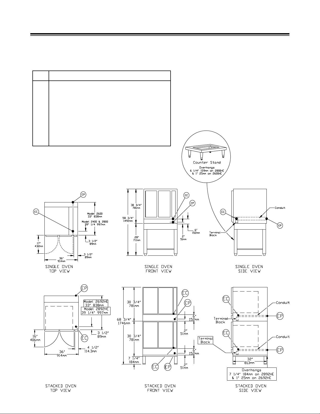
DETAILS & DIMENSIONS
SERVICE CONNECTIONS
Electrically Operated
EC Electrical Connection- for incoming power supply wires
on terminal block.
EP
Power Supply- 1 3/4” (44mm) DIA. access holes for
power supply wires. Use wire suitable far at least 90oC.
Nominal amp per line wire per oven 10.4KW
Volts 1pH 3pH
208 (197-219) 50 30
230 (220-240) 44 25
480 (460-500) -- 12.5
Details of other electrical systems available upon request.
NOTES: Allow 2” space from side wall and 2”
space from rear wall if adjoining wall is combustible.
All stands are 32” front to back. When used
with deep oven overhang may either front or
back as desired (recommended overhang is
in back). Allow 3 3/4” on front for door handles
and controls.
2
Page 5
INSTALLATION
ASSEMBLY INSTRUCTIONS FOR 28” MODULAR (SINGLE OR MULTIPLE) OVENS STAND: (Figure 1)
Insert adjustable foot (#5) to leg assembly (#4).
1.
Assemble leg assembly (#4) to top frame assembly (#1) using hardware (#6 & #7).
2.
Place into position front and rear channel assembly (#2) and side channel (#3).
3.
Use hardware (Item #7) plain washer and (Item #6) 3/18-16 hx. hd. cap screw to mount stand to oven.
4.
When joining stands, do not attach side channel skirt, two legs may be discarded joining stands together.
5.
“OBSOLETE”
ITEM #
1 99-0838 99-0838 TOP FRAME ASSEMBLY - PAINTED*
2 99-0840 FRONT & REAR CHANNEL ASSEMBLY
3 99-0841 SIDE CHANNEL
4 90-9131 90-9114 LEG ASSEMBLY
5 10-0644 10-0644 FOOT
6 10-2034 10-2034 3/18-16 HX. HD. CAP SCREW
7 10-2401 10-2401 3/8 PLAIN WASHER
8 10-3035 10-3035 3/8-16 HX. NUT
* PAINTED PARTS ARE NO LONGER AVAILABLE (OBSOLETE).
ITEMS 2 & 3 ARE LOOSE PARTS AND THEY ARE TIED TOGETHER WITH MOUNTING OF OVEN TO STAND.
*PAINTED PART #
STAINLESS STEEL
PART # DESCRIPTION
Figure 1.
3
Page 6
INSTALLATION
IMPORTANT NOTE: If stacked ovens are adjacent to moisture producing equipment (i.e. kettles or steam cookers) it is necessary to seal the
seam between the stacked ovens and the moisture producing equipment to prevent condensation from entering control section of the bottom
oven. Silicone synthetic rubber is recommended for a sealant.
Figure 2.
ASSEMBLY INSTRUCTIONS (208/230V & 440/480V) STACKED OVENS WITH 7” STAND: (Figure 2)
Mount bottom oven on stand using hardware (#4 & #5). Either oven may serve as bottom oven.
1.
Stack top oven on bottom oven. Be sure ovens in position are level front to back, side to side and diagonally.
2.
Place lower oven in position, level it and make necessary adjustments prior to placing second oven. This
includes all adjustments to doors. The screws that hold the front trim at the top of the oven on the lower oven
should be removed prior to placing the top oven in position. This will permit removal of the cover or front trim
so that door adjustments may be made at a later time.
Pull bottom trim panel forward to release from spring catches and lower to full open position as shown in gure
3.
2 above.
Remove screws and circuit breaker cover (#3 & #6) from 208/230V oven to make power supply connection.
4.
Remove screws and circuit breaker cover (#3 & #2) from 440/480V oven to make power supply connection.
Bring power supply line in through 1 3/4” diameter knockout in rear panel.
If space is available, right side panels can be removed from ovens to increase accessibility in making power
5.
connections.
“OBSOLETE”
ITEM #
1 99-0851 99-0853 SUPPORT STAND 7” HIGH
2 99-3335 99-3335 TERMINAL BLOCK COVER
3 10-2352 10-2352 BINDING HD. SCREW TYPE A #8 x 1/2” LG.
4 10-2401 10-2401 PLAIN WASHER 3/8
5 10-2034 10-2034 HX. HD. CAP SCREW 3/8-16 x 3/4 LG.
6 99-3293 99-3293 CIRCUIT BREAKER COVER
* PAINTED PARTS ARE NO LONGER AVAILABLE (OBSOLETE).
*PAINTED PART #
STAINLESS STEEL
PART # DESCRIPTION
4
Page 7
INSTALLATION
Figure 3
ASSEMBLY INSTRUCTIONS 7” STAND FOR MODULAR STACKED OVENS: (Figure 3)
Screw legs (#4) into top frame assembly (#1).
1.
Drop front and rear angle assembly (#2) and side angle (#3) over top frame assembly (#1).
2.
“OBSOLETE”
ITEM #
1 99-0845 99-0845 TOP FRAME ASSEMBLY - PAINTED*
2 99-0857 FRONT & REAR ANGLE ASSEMBLY
3 99-0854 SIDE ANGLE
4 10-0631 10-0631 LEG
* PAINTED PARTS ARE NO LONGER AVAILABLE (OBSOLETE).
ITEMS 2 & 3 ARE LOOSE PARTS AND THEY ARE TIED TOGETHER WITH MOUNTING OF OVEN TO STAND.
*PAINTED PART #
STAINLESS STEEL
PART # DESCRIPTION
5
Page 8

INSTALLATION
Figure 1W
6
Page 9

INSTALLATION
Figure 2W
7
Page 10

INSTALLATION
Figure 3W
8
Page 11

INSTALLATION
Figure 4W
9
Page 12

INSTALLATION
Figure 5W
10
Page 13

INSTALLATION
Figure 6W
11
Page 14

INSTALLATION
Figure 7W
12
Page 15

INSTALLATION
Figure 8W
13
Page 16

INSTALLATION
Figure 9W
14
Page 17

INSTALLATION
Figure 10W
15
Page 18

INSTALLATION
Figure 11W
16
Page 19

OPERATION
Do not attempt to operate oven without rst reading the
following instructions thoroughly.
Be sure that power is available to unit.
1.
Be sure that both the blower guard and deector are
2.
properly mounted.
Turn on power with doors open.
3.
Arrange shelf positions dependent upon item to be
4.
baked or roasted.
Close doors. Blower should come on and rotate
5.
clockwise, otherwise unit is not operating correctly.
If blow does not start or starts and immediately
stops, this may indicate an electrical overload. Reset
circuit breakers on control panel. If blower still does
not operate, this is an indication of incorrect wiring
or other electrical problems. Have your electrician
check the wiring if this is an initial operation, other-
wise contact your local service agency. For a Service
Agency Listing Go To: http://www.mi.com/ and click
on Service or call our factory at 866-698-3188 and
ask for Service Department.
Preheat to desired temperature and allow to cycle
6.
once for 15 minutes to obtain even temperature
throughout oven.
Oven is ready to cook and may be loaded when
7.
indicator light goes off. The load should be adjacent
to the oven to facilitate rapid loading so that doors
will be open as short a time as possible.
If using the convection oven for long term roasting of
8.
meats, sh or poultry, place about a quart of water
in a suitable container in the oven under a trivet in
the same pan as the product.
Close doors and set to desired cooking time.
9.
Interior lights nay be turned on or off as desired. If
10.
light fail to operate reset circuit breaker on control
panel. If lights still fail to operate this indicates faulty
bulbs. If light still fail to operate this indicates an
internal electrical fault and an electrician should be
notied.
Bell will sound when cooking is complete. Oven is
11.
ready to unload.
If oven temperature is to be lowered, set thermostat
12.
to the desired temperature. Keep the blower operating by leaving the right door closed and left door
open. When indicator light comes on, oven is at lower
temperature. Close both doors. When indicator light
goes off the oven is ready to use.
When oven is to be turned off, turn oven thermostat
13.
off, turn power switch off and leave doors ajar.
NOTE:
Fan should always operate in a clockwise rotation.
CONTROL PANEL COMPONENTS:
Interior Light Switch: This switch controls the interior oven
lights. These are special heat resistant 120 volt lamps. Proper
replacements are available through the factory. It is not advisable to use inferior hardware store bulbs as replacements.
Power On Switch: This switch is located on the bottom of the
control panel. This switch must be ipped to the right before
any current can ow to either the thermostat of the fan motor.
It is a single pole, single throw toggle switch and its purpose
is to insure that the convector fan motor is on when the oven
is on. With the switch in the left (off) position the oven will not
operate.
Light Reset Switch: This switch is located on the control panel
above the Power On switch. it serves as a circuit breaker for
the oven lights.
Circuit Breaker: This switch controls the power to the control
panel and fan motor of the oven. If an overload should occur
the switch will ip down (off) automatically. In doing so, it breaks
the circuit to the contactors, shutting down the entire oven.
Power to the oven is restored by ipping the external circuit
breaker switch up (on) provided the cause of the overload has
been remedied.
NOTE:
When working on the heating elements the internal circuit
breaker of the oven should be shut down.
Thermostat Control: With the Power On switch in the ght
hand (on) position, the thermostat control may be dialed to a
desired temperature. Heating elements will turn on and off to
maintain constant temperature at the thermostat setting.
Indicator Light: the red light glows when the heating ele-
ments are on. It will go on and off as the oven cycles.
Motor Reset Button: This serves as an automatic circuit
breaker on the convector motor circuit to protect the motor
from sudden overloads. Pressing the motor rest button will
re-establish the circuit provided the cause of the overload has
been remedied.
60 Minute Timer: For timing cooking cycles of less than 60
minute durations. Upon completion of timing cycle a bell will
sound to signify that the present time has elapsed and foods
may be removed.
5 Hour Timer: For timing cooking cycles of more then one
hour and upon completion of timing cycle a bell will sound to
signify that the present time has elapsed and foods may be
removed.
17
Page 20

MAINTEANCE
PREVENTIVE MAINTENANCE
A good preventive maintenance program in the form of daily
cleaning procedures is outlined in the following steps.
Remove oven shelves and wash in mild detergent and
1.
water. Rinse and dry.
Remove left and right hand shelf supports by lifting up and
2.
out toward center of oven. Wash, rinse and dry.
Remove fan guard by lifting up and out. Wash, rinse and
3.
dry.
Wash interior sides, bottom and top with mild detergent
4.
and water. A stainless steel cleaner, not polish, should be
used for the interior. Rinse and dry.
Replace fan guard shelf supports and shelves.
5.
Wash both sides of doors using a stainless steel cleaner.
6.
Rinse and dry.
REMOVAL & REPLACEMENT OF DOOR STYLE A:
Refer to gure 4 on page 19:
Remove screw (#1) from hinge plate (#2) at top and bot-
1.
tom and remove door from oven.
Remove side channel (#3) and slide out glass insert (#4)
2.
from door trim (#5).
Assemble new glass insert in reverse order.
3.
REPLACE &/OR ADJUST CATCH:
Refer to gure 4 on page 19:
Follow above instructions rst.
1.
Remove glass insert (#4) from door trim (#5).
2.
Take off retaining clip (#6) remove old catch (#7) and
3.
install new catch.
REPLACE DOOR FILLER STRIP:
Refer to gure 4 on page 19:
Remove ve drive screws (#9) and remove ller strip (#8).
1.
Add new ller strip (#8) and secure drive screws (#9). If
ller strip is secured with pop rivets, drill out.
For door ller strip addition (#8) see view A. Drill ve 1/8”
2.
diameter holes using door ller strip as a template and
secure with ve drive screws (#8 & #9).
REMOVAL & REPLACEMENT OF DOOR STYLE B:
Refer to gure 5 on page 19:
Remove screw (#1) from hinge plate (#2) at top and bot-
1.
tom and remove door from oven.
Remove side channel (#3) and slide out glass insert (#4)
2.
from door trim (#5).
Assemble new glass insert in reverse order.
3.
Thermostat Calibration
If the oven components are operating but the unit is not cooking properly, the thermostat may need calibration. To calibrate,
proceed as follows:
Attach a thermocouple lead to the bulb of the thermostat
1.
and close oven doors.
Place power switch in the ON position.
2.
Set thermostat dial at 400°F and carefully remove the
3.
switch control knob.
Allow the unit to heat until the indicator light has gone
4.
out twice.
Note the temperature reading on the thermocouple.
5.
a) If the temperature reading is off 500 or more, the thermostat must be replaced.
b) If the reading is off less than 50°F, adjust the thermostat
setting using a ne blade screw-driver in the stem of the
thermostat.
With the oven temperature set at 400°F, the cycling
6.
should retain a peak of 420°F and a low of 380°F after two
stabilizing cycles. A good indication of proper calibration is
the temperature at which the burners ignite and shut off.
It should be:
Cut off 400-405°F
Cut in 380-385°F
After completing calibration, apply Duco cement or
7.
equivalent to the adjusting screw of the thermostat and
replace the knob.
Fan Motor Removal
Motor removal is completed from inside the oven. With external
circuit breaker shut off, proceed as follows:
Remove fan guard.
1.
Remove four nuts and clips from motor assembly.
2.
Pull motor forward, carefully disconnect electrical wiring,
3.
and slide motor off screws.
Install replacement motor assembly as required.
4.
Thermostat Removal
Remove six screws from top panel on right side of oven.
1.
Remove four screws from rear panel.
2.
Remove four screws from control panel.
3.
Remove right side panel.
4.
Remove ve screws that secure perforated capillary tube
5.
guard to oven liner.
Slide thermostat bulb out from clips and through hole in
6.
side of oven.
Slide entire assembly out front of oven through the control
7.
area.
Install replacement thermostat as required.
8.
18
Page 21

Figure 4
MAINTEANCE
Figure 5
19
Page 22

ILLUSTRATED PARTS
Figure 6
20
Page 23

ILLUSTRATED PARTS
Figure 7
21
Page 24

Figure 7 (see page 21)
ILLUSTRATED PARTS
STANDARD
ITEM #
1 99-1570 99-1569 TOP PANEL
2 99-1574 99-1578 L.H. PANEL ASSY
3 99-1576 99-1580 R.H. PANEL ASSY
4 99-1572 99-1572 REAR PANEL
5 10-1295 10-1296 L.H. RACK SUPPORT
6 10-1295 10-1296 R.H. RACK SUPPORT
7 99-1625 99-1625 CLIP
8 10-1988 10-1988 WING SCREW
9 99-0959 99-0959 DEFLECTOR ASSY
10 10-5957 10-5957 FAN GUARD
11 10-5453 10-5453 BLOWER WHEEL
12 10-4472 10-4472 KNOB
13 99-3049 99-3049 CONTROL PANEL ASSY
14 10-4714 10-4714 THERMOSTAT
15 99-3026 99-3026 GLASS ASSY
16 10-5148 10-5148 LIGHT BULB
17 10-5149 10-5149 SOCKET ASSY
18 99-3052 99-3052 INSULATION
19 10-6209 10-6209 DOOR SIWTCH
20 99-0665 99-0665 MOTOR ASSY - 60 Hz, 115/230V
21 99-3035 99-3035 BOTTOM PANEL ASSY
22 10-1984 10-1984 1/2”-13 ALLEN SOC. HD. CAP SCREW
23 99-3333 99-3333 WHEEL PULLER
24 99-3332 99-3332 COLLAR (USE WITH SMALL HUB)
25 10-1985 10-1985 5/16”-18 ALLEN SOC. HD. CAP SCREW
26 10-1986 10-1986 5/16”-24 ALLEN SOC. HD. CAP SCREW
27 99-3040 99-3040 CAPILLARY TUBE GUARD
28 99-0951 99-0951 CLIP
29 10-2335 10-2335 HEX NUT 5/16”-18
30 10-2117 10-2117 5/16”-18 HEX HD. CAP SCREW 2-1/4” LG.
31 99-3039 99-3039 THERMOSTAT GUARD
PART #
99-0675 99-0675 MOTOR ASSY - 50 Hz, 110/220V
99-0676 99-0676 MOTOR ASSY - 60 Hz, 460V
DEEP
PART # DESCRIPTION
22
Page 25

Figure 8
ILLUSTRATED PARTS
23
Page 26

ILLUSTRATED PARTS
Figure 8 (see page 23)
ITEM
# PART # DESCRIPTION
INSIDE OVEN LINER (STYLE B):
1 10-6084 HEATING ELEMENTS, STANDARD, 3100 WATTS, 208V
10-6085 HEATING ELEMENTS, STANDARD, 3100 WATTS, 230V
10-6086 HEATING ELEMENTS, STANDARD, 3100 WATTS, 440/479V
10-6087 HEATING ELEMENTS, STANDARD, 3100 WATTS, 480V
10-6678 HEATING ELEMENTS, DEEP, 4000 WATTS, 208V
10-6843 HEATING ELEMENTS, DEEP, 4000 WATTS, 230V
10-6844 HEATING ELEMENTS, DEEP, 4000 WATTS, 440/479V
10-6845 HEATING ELEMENTS, DEEP, 4000 WATTS, 480V
BELOW OVEN LINER (STYLE B):
2 10-6650 HEATING ELEMENTS, STANDARD , 1400 WATTS, 208V
10-6651 HEATING ELEMENTS, STANDARD , 1400 WATTS, 230V
10-6652 HEATING ELEMENTS, STANDARD , 1400 WATTS, 440/479V
10-6653 HEATING ELEMENTS, STANDARD , 1400 WATTS, 480V
10-6677 HEATING ELEMENTS, DEEP , 1800 WATTS, 208V
10-6684 HEATING ELEMENTS, DEEP , 1800 WATTS, 230V
10-6685 HEATING ELEMENTS, DEEP , 1800 WATTS, 440/479V
10-6686 HEATING ELEMENTS, DEEP , 1800 WATTS, 480V
BOTTOM ELEMENTS (STYLE A):
3 10-6527 HEATING ELEMENTS, STANDARD + DEEP , 1400 WATTS, 208V
10-6528 HEATING ELEMENTS, STANDARD + DEEP , 1400 WATTS, 230V
10-6529 HEATING ELEMENTS, STANDARD + DEEP , 1400 WATTS, 440/479V
10-6530 HEATING ELEMENTS, STANDARD + DEEP , 1400 WATTS, 480V
4 99-3055 RETAINING SHIELD ASSY, STANDARD
5 99-3043 RETAINING SHIELD ASSY, DEEP
6 10-5396 TRANSFORMER, 440-480V
7 10-5466 CONTACTOR, 208V
8 10-5467 CONTACTOR, 230V, 440-480V
9 10-5503 TERMINAL BLOCK, 440-480V UNITS ONLY
10 10-6520 CIRCUIT BREAKER, 208/230V, 70 AMPS
11 99-1882 INSULATION
12 99-1653 BRACKET, 208/230V
99-1820 BRACKET, 440/480V
13 10-1735 #8 SHEET METAL SCREW
14 99-1789 WASHER
15 10-2382 WING NUT #8-32
16 10-2356 WELD BRACKET #8-32
17 10-1954 PAN HD. SLOTTED MACHINE SCREW #8-32 x 1-5/8” LG.
24
Page 27

Figure 9
ILLUSTRATED PARTS
Figure 9
ITEM
# PART # DESCRIPTION
*1 99-3049 CONTROL PANEL ASSY
2 10-4472 CONTROL KNOB 9 10-6264 ON-OFF TOGGLE SWITCH
3 99-3027 NAMEPLATE PANEL 10 10-5016 PILOT LIGHT
4 10-6415 NAMEPLATE BEZEL 11 10-6267 LIGHT RESET, 208/230V
5 10-4714 THERMOSTAT 12 10-6270 LIGHT RESET, 440/480V
6 10-5520 60 MINUTE TIMER 13 10-6265 MOTOR REST, 208/230V
7 10-5553 5 HOUR TIMER 14 10-6269 MOTOR RESET, 440/480V
*DOES NOT INCLUDE THERMOSTAT.
“COMPLETE”
ITEM
# PART # DESCRIPTION
8 10-6280 CIRCUIT BREAKER
25
 Loading...