

Page 1
SERVICE & PARTS MANUAL
Models:
Power Saver II Electric Convection Oven
2600HE
MARKET FORGE CANADA LTD.
Mississauga, Ontario, Canada
Form Number 17-0393 3/81
2692HE
2800HE
2892HE
Page 2

TABLE OF CONTENTS
Paragraph Page
SECTION 1 INTRODUCTION
1.1 Description 1-1
1.2 Oven Components 1-1
1.3 Basic Functioning 1-1
1.4 Service 1-1
SECTION 2 INSTALLATION
2.1 Receiving 2-1
2.2 Assembly 2-1
2.2. 1 Single Oven On Modular Base 2-1
2.2.2 Oven On 7"{178mm) Stand 2-1
2.2 3. Stacked Ovens On 7" (178mm)
Stand 2-1
2.2.4 Oven on 28"( 711 mm) Open
Stand 2-1
2.3 Electrical Connection 2-3
2.4 Installation Check-Out 2-3
2.4.1 Oven Check Out & Adjustments 2-3
2.4.2 Shut -Down Procedure 2-4
SECTION 3 OPERATION
3.1 Operating Controls and Indicators 3-1
3.2 Operating Procedures 3-1
3.2.1 Preheating 3-1
3.2.2 Cooking 3-1
SECTION 4 PRINCIPLES OF OPERATION
4.1 General 4-1
4.2 Heating Circuits 4-1
4.3 Electrical Circuits and Controls 4-1
4.3.1 Circuit Breaker 4-1
4.3.2 On-Off Switch 4-1
4.3.3 Door Interlock Switch 4-1
4.3.4 Thermostat Control 4-1
4.3.5 Indicator Light 4-1
SECTION 5 TROUBLE-SHOOTING
5.1 General 5-1
Paragraph Page
5.2 Trouble-Shooting Guide 5-1
5.3 Electrical Fault Isolation 5-2
5.4 Electrical Trouble-Shooting
Procedures 5-2
5.4.1 Incoming Power 5-2
5.4.2 Electrical Inspection 5-2
5.4.3 Thermostatic Control 5-2
5.4.3.1 Thermostat Contacts 5-2
5.4.3.2 Thermostat Capillary 5-2
5.4.4 Wiring 5-3
SECTION 6 MAINTENANCE
6.1 General 6-1
6.2 Preventive Maintenance 6-1
6.3 Adjustment Procedures 6-1
6.3.1 Oven Door Adjustments 6-1
6.3.1.1 Door Catch Adjustment 6-1
6.3.1.2 Door Switch Adjustment 6-1
6.3.1.3 Oven Door Horizont al Adjustment 6-2
6.3.1.4 Oven Door Vertical Adjustment 6-2
6.4.1 Control Panel and Contactor
Removal 6-2
6.4.2 Right Side Panel Removal 6-2
6.4.3 Fan Disassembly and Repair 6-2
6.4.3.1 Fan Blade Removal 6-2
6.4.3.2 Fan Motor Removal 6-3
6.4.4 Heating Element Removal 6-3
6.4.4.1 Rear Heating Element Removal 6-3
6.4.4.2 Bottom Heating Element Removal 6-3
6.4.5 Thermostat Removal 6-3
SECTION 7 ILLUSTRATED PARTS LIST
7.1 General 7-1
7.2 Ordering Information 7-1
7.3 Index Of Illustrated Parts List 7-1
iii 17-0393
Page 3

LIST OF ILLUSTRATIONS
17 0393
IV
Figure
SECTION 2 INSTALLATION
2-1 Counter Stand Assembly 2-2
2-2 Stacked Oven Assembly 2-2
2-3 Open Stand Assembly (Inverted) 2-2
2-4 Electrical Connection 2-3
SECTION 3 OPERATION
3-1 Operating Controls & Indicators 3-2
SECTION 5 TROUBLE SHOOTING
5-1 Wiring Diagram, 208/240 V 5-4
5-1 Wiring Diagram, 440/480 V 5-5
5-3 Wiring Diagram, 220/240/380/415V. 5-6
LIST OF TABLES
Table Page
SECTION 3 OPERATION
3-1 Operating Controls & Indicators 3-2
Figure Page
5-4 Schematic Diagram, 208/240/380 V. 5-7
5-5 Schematic Diagram, 440/460/480 V. 5-8
SECTION 6 MAINTENANCE
6-1 Blower Guard/Deflector Assembly 6-1
6-2 Wheel Puller Kit Components 6-2
SECTION 7 ILLUSTRATED PARTS LIST
7-1 Cabinet & Frame Assembly 7-2
7-2 Door Assembly 7-4
Heating Element Assembly 7-6 7-3
Control Panel Assembly 7-8
Table Page
SECTION 5 TROUBLE-SHOOTING
5-1 Trouble-Shooting Guide 5-1
5-2 Electrical Fault Isolation Guide 5-3
Page 4

SECTION 1 INTRODUCTION
1-1
17-0393
This service and parts manual contains general information, installation, operation, principles of operation, trouble-
shooting and maintenance information for the Market Forge Power Saver II High Efficiency Electric Convection
Oven. Also included are parts lists, in which each replaceable part is identified and shown in an accompanying
exploded view.
1.1 DESCRIPTION
The Market Forge Power Saver II High Effi ciency
Electric Convection Oven is an electrically powered
convection ove n designed to achieve high-volume
cooking with a minimum of power consumption. The
unit consists of a heavily insulated cooking
compartment fitted with a convector fan and heated by
electric elements. All oven controls are located on a
recessed panel on the right front of the oven as seen
from the front.
1.2 OVEN COMPONENTS
The major assemblies of the Power Saver II are
the stainless steel or baked enamel-finish cabinet
enclosure, solid doors, stainless steel cooking
compartment with nine-position shelf supports,
heating element and contactor assembly, and control
panel assembly. Controls and indicators include the
thermostat, main power switch, ELEMENTS on
indicator light, 60-minute and 5-hour timers, and twopole circuit breaker. The oven is available in a variety
of mounting configurations: 7" 178mm high counter
stand, on legs with shelf and optional storage rack, or
stacked on top of another Power Saver II with the
bottom unit on 6" 152mm stainless steel legs.
1.3 BASIC FUNCTIONING
The Power Saver II becomes operational when the
power switch is placed in the ON position, doors are
closed, and thermostat set. Contactors located in the
control section close the
circuit to heating elements located underneath and at
the rear of the cooking chamber. When the chamber
reaches the preset temperature, the thermostat
contacts open, causing the contactors to interrupt the
circuit to the heating elements. When the temperature
in the chamber drops enough to close the thermostat
contacts, the circuit closes again. Any number of such
cycles might occur during the cooking time, indicated
by the ELEMENT indicator light coming on and off.
1.4 SERVICE
Required service, both preventive and corrective, is
explained in section 6. Should repairs be required, a
network of authorized agencies is available to assist
with prompt service. A current directory of Authorized
Service Agencies may be obtained by contacting:
Product Service Department
Market Forge
35 Garvey Street
Everett, Massachusetts 02149
(617) 387-4100
Product Service Department Market Forge
Canada, Ltd. 1375 Aimco Blvd., Unit 5
Mississauga, Ontario, Canada L4W 1B5
(416)621-9252
The model and serial number must be referenced
when corresponding with Market Forge. The data
plate with serial number is located on the center of the
bottom front trim ledge.
Page 5

SECTION 2 INSTALLATION
2.1 RECEIVING
The unit is shipped strapped and bolted to a skid,
and covered by a corrugated container. Packing
materials must be removed prior to installation
Examine shipment for external or internal damage
and completeness. A complete shipment normally
includes the oven unit, two shelf supports and five
interior shelves, a carton containing stand
components (if a stand has been specified), and a
packet of documents pertaining to the unit.
GENERAL CAUTION: Tilt oven onto back or left
side (seen from front) to access bottom when
necessary DO NOT AT ANY TIME LAY THE OVEN
DOWN ON ITS TOP , RIGHT SIDE, OR FRONT TO
DO SO MAY DAMAGE THE EQUIP MENT AND
INVALIDATE THE WARRANTY.
2.2 ASSEMBLY
Set-up assembly procedures for the various oven
configurations are described in the following
paragraphs. Assembly requires that the stand be
completely assembled first, then set in place and the
oven mounted upon it before service connections
are completed.
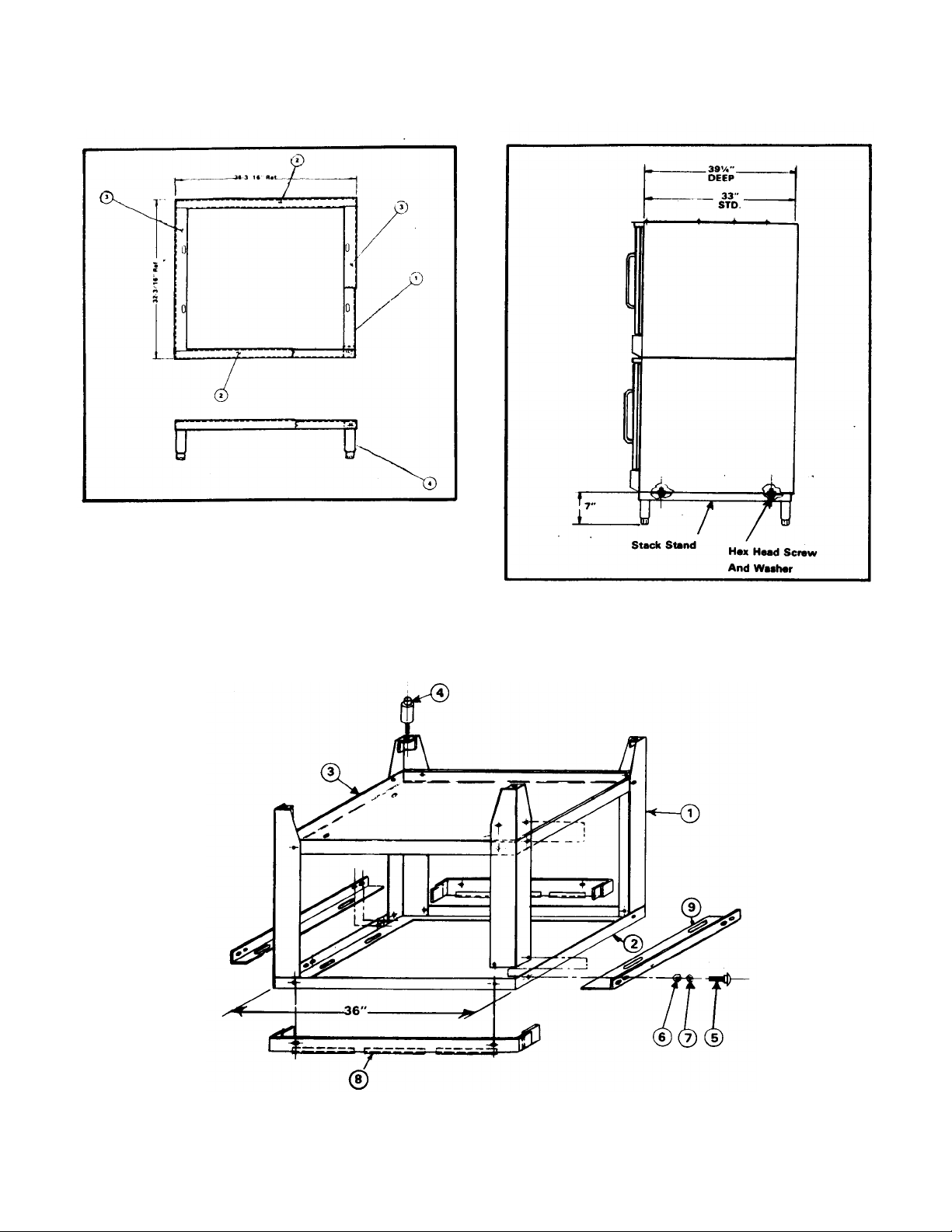
2.2.3 Stacked Ovens on 7" (178mm) Stand
1. Mount bottom oven on stand (Figure 2-2) using
hex head screws and washers provided.
NOTE
Stand is 32" 813mm front to back. When used
with deep oven, overhang may be either front or
back, as desired. (Recommended overhang is in
back)
2. Remove upper trim strip screws on front of lower
oven. This is necessary to permit door
adjustment, if required, at a later date.
3. Stack top oven on bottom oven.
NOTE
If stacked ovens are adjacent to moisture
producing equipment (such as kettles or steam
cookers) it is necessary to prevent
condensation from entering the control section
of the bottom oven. The seam between the two
ovens, and between the ovens and the moisture
producing equipment, must be sealed with
silicone synthetic rubber or equal high grade
sealant.
4. Proceed to subsection 2.3.
2.2.1 Single Oven on Modular Base
1. Screw adjustable feet into cabinet base.
2. Mount oven to base using four 3/ 8 - 1 6 x 3/4 Ig.
hex head cap screws and four 3/ 8 plain
washers provided.
3. Proceed to subsection 23.
2.2.2. Oven on 7" (178mm) Stand
1. Screw legs ( Figure 2-1, #4) into top frame assembly
(1).
2. Place into position front and rear channel assembly
(2) and side angles (3). These items are loose parts
and are secured with mounting of oven to stand.
3. Mount oven to stand using four % - 1 6 x % Ig. hex
head cap screws and four % plain washers
provided.
4. If oven is to be stacked, proceed to paragraph 2.2.4.
2.2.4 Oven on 28" (711mm) Open Stand
1. Plac e top frame (Figure 2-3, #2) upside down on a
clean, smooth surface.
2. Place front and rear angle assemblies (8)
(Stainless stands only) and legs (1) into position.
3. Align holes in legs, frame and angles. Secure
using carriage bolts, lockwashers and hex nuts
provided.
4. Align holes in shelf (3) with leg holes and secure
using hardware (5,6,7).
5. Screw adjustable feet (4) into stand legs.
6. Install four clips for oven rack supports inside top
frame using hardware (5,6,7) (included with rack
support opt ion).
7. Place stand in upright position. Install rack.
2-1
17 0393
Page 6
2-2 POWER SAVER II ELECTRIC CONVECTION OVEN
Figure
2-1
Counter Stand Assembly
. 17-0393
Figure 2-2 Stacked Oven Assembly .
Figure 2-3 Open Stand Assembly (Inverted)
Page 7
INSTALLATION 23
supports (if supplied), inserting ends through
holes in clips and shelf.
8. Mount oven to stand using four 3/8 - 1 6 x 3/4 Ig.
hex head cap screws and four 3/8 plain washers
provided.
2.3 ELECTRICAL CONNECTION
Where applicable, all wiring shall be done in
accordance with the Canadian Electrical Code ANSI
C1 - 1975. Figures 5-1, 5-2 and 5-3 show the
various internal wiring configurations for the different
models and voltages.
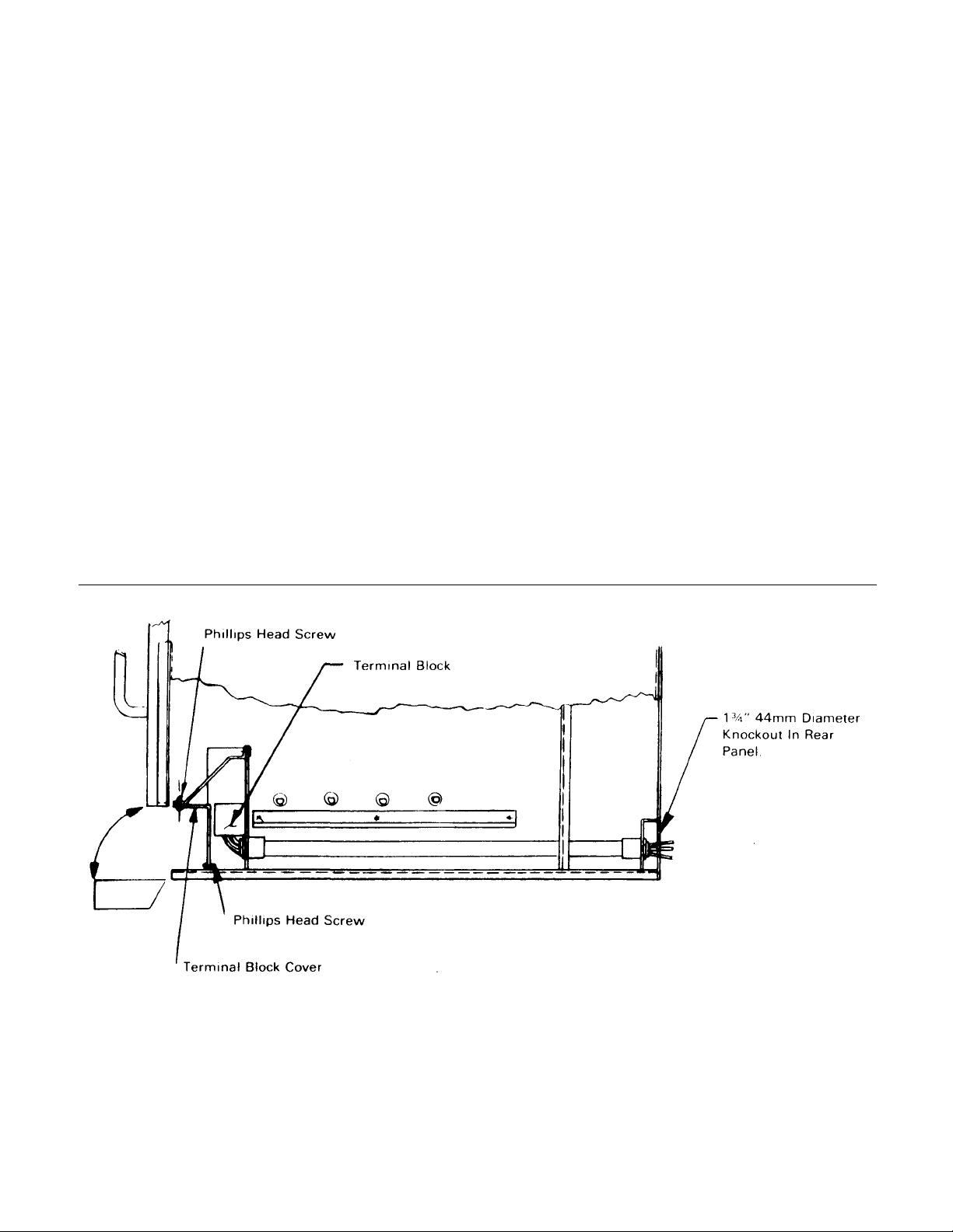
1. Pull bottom trim panel forward to release
from spring catches and lower to full open
position as shown. See Figure 2-4.
2. Remove screws and terminal block cover
(3,2).
3. Bring power supply line in through 1 3/4"
44mm access hole in rear panel and feed
through conduit.
NOTE
If desired, right side panel(s) may be removed
from oven(s) to facilitate connec tion.
5. If required, ground unit to ground lug located at
lower right (seen from front) of terminal block.
Consult appropriate electrical codes.
2.4 INSTALLATION CHECK-OUT
After the oven is completely assembled and
properly located with electrical supply connected, the
unit should be given a thorough check-out before
being put into operation. Check-out procedures for
the oven are given in subsection 2.4.1. If the unit fails
to operate as described, consult the trouble-shooting
guide in Section 5 for corrective action.
Before making this check-out, the operator must
be thoroughly familiar with the operating procedures
in Section 3, and with the function of each control
described in Table 3-1. Reference Figure 3-1 for
identification of controls.
2.4.1 Oven Check-Out & Adjustments
Begin check-out procedure with power switch and
thermostat dial in OFF positions. A final check of the
controls and connections should be made as follows:
1. Make sure that the fan guard and deflector
are properly installed. See Figure 6-1.
4. Connect line to terminal block. This is a 1/2" 1
3mm conduit connection. Use wire suitable for at
least 90°C.
17-0393
Figure 2-4 Electrical Connection.
Page 8

24
2. Seat wire shelf supports in mounting locations
inside oven, and slide shelves into position with
raised 'stop' edge at rear.
NOTE
Make sure wire shelf supports are in, not on,
brackets
3. With a level on the oven shelves, make sure the
oven is level both front and back, left and right To
adjust, turn feet in stand legs.
4. Make sure power supply is available to the oven
5. Set thermostat dial at 350°F.
6. Place power switch in the ON position with doors
open
7. Close doors. Indicator light should come on;
fan should come on and rotate clockwise
POWER SAVER II ELECTRIC CONVECTION OVEN
(seen from front). If not, see Table 5-1.
8. Indicator light will remain on while oven is heating,
and go out when preset temperature is reached.
During the heat -up period, some slight smoke or
fumes may be produced by oil or grease on metal
surfaces. This should cease after five minutes.
9. After this check is completed, turn thermostat dial
and power switch to the OFF position.
2.4.2 Shut-Down Procedure
1. For daily shut -down, place thermostat dial and
power switch in OFF position.
2. For extended shut -down, place thermostat dial and
power switch in OFF position. Leave doors ajar.
170393
Page 9

SECTION 3 OPERATION
3.1 OPERATING CONTROLS AND
INDICATORS
All the controls required to operate the oven are
listed in Table 3-1, with a short functional description
of each. Figure 3-1 shows the physical location of
each control and indicator.
3.2 OPERATING PROCEDURES
Before attempting to use the oven for cook ing, be
sure that proper electrical connections have been
made, and fan guard and deflector are properly
mounted. (See Figure 6-1).
3.2.1 Preheating
1. Arrange shelf positions according to the item to be
cooked. Refer to Test Kitchen Bulletin #41 for
correct positioning.
2. Place ON-OFF switch in the ON position and
close doors. Fan will begin rotating. If not, reset
circuit breaker.
3. Set thermostat dial to desired cooking temperature. Element indicator light should come on.
4. Allow oven to preheat for about 15 minutes.
Preheating is complete when indicator light
goes out. Do not waste energy by turning the
oven on too early,
3.2.2 Cooking
The oven is ready for cooking use when the
element indicator light goes off. The load should be
adjacent to the oven so that the doors will be open for
as short a time as possible.
1. Load oven.
2. Close doors and set timer for desired cooking time.
Buzzer will sound at end of preset interval.
3. Unload oven and proceed as follows:
a) If oven is to be turned off, place thermostat dial
and ON-OFF switch in the OFF position.
b) If oven temperature is to be lowered, reset the
thermostat to the desired temperature and close
the right door. Fan will continue to operate with
left door open. When light comes on, oven is at
lower temperature. Right door is then closed until
light comes on to show that temperature is
stabilized.
4. Place thermostat dial and ON-OFF switch in OFF
position for daily shut -down. For extended shutdown, place dial and switch in OFF position and
leave doors ajar.
3-1 17-0393
Page 10

POWER SAVER II ELECTRIC CONVECTION OVEN
1
REF.
3-2 POWER SAVER
II
TABLE 3-
OPERATING CONTROLS AND INDICATORS
FIG.
3-1
DESCRIPTION FUNCTION
Regulates oven temper-
1 Thermostat Control
ature. Controls heating
element operation.
Electric timer to aid
2 60-Minute Timer
operator in timing cook ing
cycle. Does not control
oven operation.
3 5-Hour Timer Same as 60-Minute Timer.
Controls electrical power to
4 ON-OFF Switch
thermostat and fan motor.
Must be in ON position for
oven to operate.
Indicates when lit that
5 Indicator Light
heating elements are
operating. Cycles on and
off with thermostat control.
Protects fan motor and
6 Circuit Breaker
control circuits. Must be in
ON position for oven to
operate.
Figure 3-1 Operating Controls & Indicators
17-0393
Page 11

SECTION 4 PRINCIPLES OF OPERATION
4.1 GENERAL
The Power Saver II electric convection oven uses a
carefully designed insulation system, which achieves
optimal cooking heat from power consumed. A
convector fan distributes heated air uniformly
throughout the oven interior. Heat is supplied by
electric elements, controlled by a thermostat mounted
on the control panel.
4.2 HEATING CIRCUITS
With electrical power available, power switch on,
doors closed and thermostat set, a circuit is closed to
a contactor mounted behind the oven controls. This
contactor in turn closes, supplying power to the oven
heating elements, located beneath and at the rear of
the cooking chamber.
4.3 ELECTRICAL CIRCUITS AND CONTROLS
Input power is connected at the terminal block
mounted at the right front of the oven, behind the
hinged lower trim. The control circuit is shown in the
schematic drawings. Figures 5-4 & 5-5. They show the
relationship of each control and the sequence of
operation. A brief description of major electrical circuit
components is included in the following paragraphs.
4.3.1 Circuit Breaker
A 15 Amp circuit breaker located at the bottom of
the control panel provides overload protection for the
208/240 volt branch circuit to controls. Input
connection is made from L1 and L3 for 3-phase
connection, L1 and L2 for single-phase, and N and L3
for four-wire, 3-phase. It feeds power to the poles of
the power switch.
4-1 17 0393
4.3.2. ON-OFF Switch
Control of power to the oven control circuits is
provided by the ON-OFF Switch. It is a double-pole,
double-throw toggle switch connected between the
circuit breaker and the door switch.
4.3.3 Door Interlock Switch
The door interlock switch is a single pole, two
position microswitch with normally open contacts. The
switch lever is operated by an actuat ing bar built into
the door jamb of the right side door. When the door is
open, the bar remains retracted with the switch
contacts in the normally open position. When the door
is closed, the door pushes the actuating bar against
the switch lever to close the contacts. Connected into
the circuit for the fan and thermostat, the door switch
interrupts fan operation and deactivates the heating
circuits when the door is opened.
4.3.4 The rmostat Control
The thermostat is a bulb and capillary type system,
manually adjustable from 200-475°F 94-246°C. The
oven is put into an automatic heating cycle with the
setting of the thermostat to any of its calibrated
temperature settings. Expansion and contraction of
gas within the capillary/bellows system in response to
temperature change opens and closes the thermostat
contacts, energizing and deenergizing the heat ing
element circuit.
4.3.5 Indicator Light
The Indicator Light is wired to operate only when
the circuit is completed through the thermostat control
to the coil of the heater contactor. It is on only when
the heating elements are under power.
Page 12

SECTION 5 TROUBLE-SHOOTING
a) Indicator light burned out.
5.1 GENERAL
The information in this section is intended to assist
both the operator and service personnel in locating
the general source of problems which may occur with
the Power Saver II. Before following any of the
procedures given in this section, the operator should
be thoroughly familiar with the operating instructions
and the function
TABLE 5-1 TROUBLE -SHOOTING
of all controls described in Section 3. If the problem
cannot be readily corrected, the operator should
contact the nearest authorized Market Forge service
agency for assistance.
5.2 TROUBLE-SHOOTING GUIDE
A general trouble-shooting guide for use by service
personnel is given in Table 5-1.
GUIDE
PROBLEM
Probable Cause
1. CONVECTOR FAN FAILS TO OPERATE.
a) Power to oven is off.
b) Control circuit breaker open.
c) ON-OFF switch off.
d) Right oven door open.
e) Faulty circuit breaker, ON-OFF switch,
door switch, fan motor, wiring.
2. OVEN WILL NOT HEAT WITH THERMOSTAT AT MAXIMUM SETTING, (FAN OPERATING).
a) Faulty thermostat or wiring.
b) Thermostat contacts or coil faulty.
3. INDICATOR LIGHT FAILS TO LIGHT WITH THERMOSTAT SET, FAN OPERATING, OVEN HOT.
b) Faulty wiring.
4. ERRATIC OVEN TEMPERATURE.
a) Faulty thermostat operation.
Remedy
Locate external circuit breaker for power and place in ON
position. Reset to ON position. Place in ON position. Close
door. Test each component and connecting wiring.
Replace as required.
Test thermostat and connecting wiring. Replace as
required. Replace Thermostat.
Replace light. Check wiring and repair as needed.
Recalibrate or replace as required. See subsections 6.3.2
and 6.4.5.
5. UNEVEN HEATING.
a) One or more heating elements
inoperative.
Check wiring to elements; check for burned-out elements.
Replace as required.
5-1 17-0393
Page 13

52 POWER SAVER II ELECTRIC CONVECTION OVFN
5.3 ELECTRICAL FAULT ISOLATION
Correction of an electrical fault first requires
isolation of the fault to a single circuit or component
In most cases, the nature of the failure and its effect
upon the operation of the oven will he sufficient to
isolate it to one or more circuit elements Table 52 is
provided as a guide for isolating electrical faults
5.4 ELECTRICAL TROUBLE SHOOTING
PROCEDURES
Before performing the trouble-shooting procedures in this section, the servicer must be familiar
with the function of all controls as described in
Section 3 and the Principles of Operation described
in Section 4.
Electrical trouble-shooting procedures which
follow require access to components and terminals
of the operating controls. Electrical controls are
reached by removing the control panel as described
in paragraph 6.4.1. Wiring and terminal locations are
shown in figures 5-1, 52, and 5-3 Figures 54 and 5-5
show the circuits in schematic form.
5.4.1 Incoming Power
Before trouble-shooting any of the electrical
parts or assemblies, make sure power is being
supplied to the terminal block (figure 7-3, 8A).
With power connected to the oven an a-c voltmeter
is used to measure 208 or 240 volts (depending on
the oven model) across terminals. Make sure the
unit is properly grounded to the ground lug beside
the terminal block. If the proper voltage (as noted on
the unit rating plate) is pres ent, the fault lies in the
electrical circuits of the oven
5.4.2 Electrical Inspection
The first step in any electrical trouble-shooting
procedure is a thorough inspection of all wiring
connections. To access the electrical components,
remove panel as des cribed in subsection 6 4.1
Before removing the control panel or checking
connections or wiring, make sure incoming
power is shut off. When power is supplied, all
exposed terminals carry at least 208 volts.
Check all connections by hand to ensure that all
connection points are tightly secured. Use a
screwdriver to tighten if necessary Inspect all quickdisconnect terminals for evidence of corrosion.
Terminals in this condition should be replaced.
5.4.3 Thermostatic Control
5.4.3.1 Thermostat Contacts
Defective contacts will result in failure of the oven
to operate properly. If the oven fails to heat when the
thermostat knob is set to the desired temperature, the
fault may be the thermostat switch contacts or
thermostat wiring. When this occurs, remove the
control panel (subsection 6.4.1) and proceed as
follows:
1. Turn off power to the oven at circuit breaker
2. Disconnect all wires from thermostat terminals.
(See Figures 5-1, 5-2, and 5-3).
3. Rotate the thermostat knob to the maximum
setting. With the oven cool, a zero ohm reading
should be obtained on the ohmmeter. If zero
reading cannot be obtained, contacts are defective
and the thermostat must be replaced.
4. Remove ohmmeter and replace all leads on
terminals as shown on appropriate wiring diagram.
5.4.3.2 Thermostat Capillary
A defective or punctured capillary/bellows system
may cause continuous operation of the elements. If
continuous operation occurs and recalibration of the
thermostat as explained in subsection 6.3.2 fails to
correct the problem, the entire thermostat control
must be replaced.
WARNING
170393
Page 14

TROUBLE SHOOTING 53
a. Incoming power
c. Thermostat control
OFF switch
f. Contactor
b. Contactor coil
OFF switch
c. Door switch
a. Indicator light
TABLE 5-2 ELECTRICAL FAULT ISOLATION
FAILURE FAULT LOCATION
1 Oven will not operate when thermostat is set.
b. Door switch
d. ONe. Circuit breaker
g. Wiring
2 Intermittent operation of heaters. a. Thermostat control
c. Wiring
3. Convector fan fails to operate. a. Circuit breaker
b. ON-
d. Fan motor
e. Wiring
4. Indicator light off, (heater under power).
b. Wiring
5 Uneven heating. a. Heating elements
b. Wiring
5.4.4 Wiring
All the electrical components of the Power Saver II
(ON-OFF switch, door switch, thermostat control,
contactors, circuit breaker, fan motor, and indicator
light) are connected to each other by wiring shown in
figures 5-1, 5-2, or 5-3. If all the electrical components
are operating correctly and the incoming power has
been checked, but the unit fails to operate, the fault
lies in the wiring.
Using an ohmmeter, wiring continuity between the
connections, shown on the wiring diagrams, is readily
verified. This is best done in stages, removing only
those wires required for each continuity check. As
each lead is replaced, it should be checked for
evidence of corrosion and cleaned if necessary. All
leads must be tightly attached to provide a good
electrical connection.
17-0393
Page 15

FIG. 5-1 WIRING DIAGRAM-208/240V 60HZ 1 OR 3 PHASE
Page 16

55
Troubleshooting 5-5
Figure 5-2. Wiring Diagram — 440/480 Volt, 60 Hz, 3 Phase
Page 17

5-6
Power Saver II Electric Convection Oven
Figure 5-3. Wiring Diagram — 220/240/380/415 Volt, 50/60 Hz.. 3 Phase.
Page 18

TROUBLE SHOOTING
5-7
Figure 5-4 Schematic Diagram — 208/240/380/415 Volt, 50/60 Hz.. 1 or 3 Phase
Page 19

POWER SAVER II ELECTRIC CONVECTION OVEN
5-8
Figure 5-5. Schematic Diagram — 440/460/480 Volt, 60 Hz., 3 Phase.
17-0393
Page 20

SECTION 6 MAINTENANCE
6-1
17
-
0393
6.1 GENERAL
This section contains both preventive and
corrective maintenance information. Preventive
maintenance may be performed by maintenance
personnel at the establishment where the oven is
installed. It is recommended that us er personnel
never attempt to make repairs without the assistance
of an authorized service agency. Assistance in
service methods or a current directory of authorized
Service Agencies may be obtained from Market
Forge. (See subsection 1.3).
6.2 PREVENTIVE MAINTENANCE
A good preventive maintenance program in the
form of daily cleaning procedures is outlined in the
following steps. Use mild detergent and water for
washing unless otherwise directed.
1. Remove oven shelves. Wash, rinse and dry.
2. Remove left and right hand shelf supports by lifting
up and out toward center of oven. Wash, rinse and
dry.
3. Remove deflector and fan guard (Figure 6-1) by
lifting up and out. Wash, rinse and dry.
4. Clean interior sides, bottom and top using stainless
steel cleaner (not polish). Rinse as required and
dry.
5. Replace deflector, fan guard, shelf supports and
shelves.
6. Clean both sides of doors, using a stainless steel
cleaner. Rinse as required and dry.
6.3 ADJUSTMENT PROCEDURES 6.3.1
Oven Door Adjustments
Access to adjustable parts is obtained by first
removing upper oven trim (Figure 7-2 #17), held in
place by screws (1 and 2), and lower trim (34), which
can be pulled forward without removing hardware.
Figure 6-1 Blower Guard/Deflector Assembly.
6.3.1.1 Door Catch Adjustment
1. Loosen door catch assembly mounting screws
(Figure 7-2, 4) at top and bottom of door frame.
2. Move door catch assembly (7) in or out as required
to hold door firmly against oven front. Do not leave
any gaps or space between roller on door catch
assembly and dimple on door trim.
3. Tighten the screws (4) and replace trim.
6.3.1.2 Door Switch Adjustment
If convector fan fails to turn on when the right -side
oven door is closed and power is on (circuit breaker
and ON-OFF switch in ON positions) the door switch
may require adjustment. With upper trim removed
switch (Figure 7-2, 20) is fully exposed. Adjustment is
made by bending the actuator arm until correct
operation is obtained.
1. Bend lever to left (away from switch) to shorten
switch action throw. Bend right to lengthen throw.
2. Open and close door several times to check switch
adjustment. Repeat step 1 as required to obtain
proper ON-OFF operation of con-vector fan.
3. Replace upper trim (17).
Page 21

6-2
6.3.1.3 Oven Door Horizontal Adjustment
To adjust the doors horizontally (either left to right
or front to back, remove upper and lower trim and
proceed as follows:
1. Loosen the four hex nuts (Figure 7-2, 10)
[two at top and two (not shown) at bottom] on both
doors.
2. Close both doors, and reposition so that doors are
square with top angle and control panel. The gap
between the raised embossments of abutting door
edges should be approximately 1/32" 1mm. It is
important that this gap be maintained the full
height of the doors. Tighten nuts (10).
3. Open each door. Check that inside surface of door
trim contacts raised edge of oven liner at top and
bottom. Readjust if necessary.
4. Replace trim.
6.3.1.4 Oven Door Vertical Adjustment
To adjust the doors vertically:
1. Loosen the two hex nuts (Figure 7-2, 9).
2. Back off top door pivot pin (8).
3. Reposition door by turning bottom door pivot pin
(8). Turn pin clockwise (up) or counter-clockwise
(down) as required. Top of doors should be level
with each other and equally spaced between top
and bottom trim.
4. Retighten the two hex nuts.
5. Replace trim.
POWER SAVER II ELECTRIC CONVECTION OVEN
6.4.2 Right Side Panel Removal
1. Remove six screws from top panel (Figure 7-1, 11)
on right side.
2. Remove four screws from rear of right side panel.
(2).
3. Remove four screws (22) from control panel. (14).
WARNING
Controls carry 208 volts. Make sure external circuit
breaker is shut off before removing panel, to avoid
accidental shock or short circuit.
4. Remove right side panel.
6.4.3 Fan Disassembly and Repair
6.4.3.1 Fan Blade Removal
Removal of the fan requires use of a wheel puller
kit (part #99-3334) supplied by Market Forge. Wheel
puller kit components are shown in Figure 6-2. To
remove fan blade, proceed as follows:
1. Remove deflector and fan guard (Figure 7-1, 18,
17).
2. Remove Allen head set screws which secure fan to
motor shaft.
3. Install wheel puller over hub of fan using Allen
head cap screws.
4. Gradually tighten hex bolt on wheel puller until fan
slides off motor shaft.
5. Remove wheel puller from fan blade and reinstall
replacement fan on motor shaft as required.
6.4.1 Control Panel and Contactor Removal
All controls of the oven are serviceable from the
front. By removing the control panel (Figure 7-1, 14)
all panel components and the contactor mounted
behind the panel are accessible for replacement.
1. Remove screws (Figure 7-1, 22) from control panel
(14).
2. Pull panel forward being careful to avoid damaging
controls and wiring.
WARNING
Controls carry a minimum of 208 volts. Make sure
external circuit breaker supplying power to the
oven is shut off before removing panel.
3. Remove contactor (Figure 7-3, 6) or panel
components identified in Figure 7-4 as required
and reassemble.
17-0393
Figure 6-2 Wheel Puller Kit Components .
Page 22

MAINTENANCE 6-3
6.4.3.2 Fan Motor Removal
Motor removal is completed from inside the oven
With external circuit breaker shut off, proceed as
follows 1 Remove deflector and fan guard (Figure 71, 18,17)
2. Remove four nuts (20) and clips (19, 21 and 23)
from motor assembly.
3. Pull motor forward. Carefully disconnect electrical
wiring.
4. Slide motor off screws. Identify and tag wires.
5. Install replacement motor assembly as required
6.4.4 Heating Element Removal
6.4.4.1 Rear Heating Element Removal
Removal of rear heating elements (Figure 7-3, 1)
is completed from inside the oven. With external
circuit breaker shut off, proceed as follows:
1. Remove oven shelves, shelf supports, (Figure 7-1,
12) deflector (18) and fan guard (1 7).
2. Remove screw from heating element bracket at
top right rear of oven liner.
3. Lift element up and off retaining brackets (Figure
7-3, 3).
4. Gently pull bracketed end of element away from
oven liner. Remove terminal screws from
elements and tag wires for identificat ion.
5. Replace with new element as required, proceeding
in reverse sequence of above.
6.4.4.2 Bottom Heating Element Removal
Removal of bottom heating elements is completed
from the front of the oven. With external circuit
breaker shut off, proceed as follows:
1. Lower hinged bottom front panel of oven, (Figure
7-2, 34).
2. Remove wing nut (Fig. 7-3, 12) and washer (10)
from underside of retaining panel (9).
3. Remove screws (11) from front of retaining panel,
and lower panel.
4. Remove screws (4) from heating element brackets.
5. Gently slide element (2) out. Remove terminal
screws from elements and tag wires for
identification.
6. Replace with new element as required, proceeding
in reverse sequence of above.
6.4.5 Thermostat Removal
1. Remove screws (Figure 7-1, 22) from control panel
(14).
2. Remove five screws that secure perforated
capillary tube guard (9) to oven liner.
3. Slide thermostat bulb out from clips (19 & 21) and
thread capillary tube through hole leading to the
control area.
4. Remove thermostat control (Fig. 7-4, 4) from
control panel.
5. Slide entire assembly out front of oven through the
control area.
6. Install replacement thermostat as required.
17-0393
Page 23

SECTION 7 ILLUSTRATED PARTS LIST
7.1 General
This section contains a complete listing of all
replaceable parts of the Power Saver II Electric
Convection Oven. For the purpose of parts
identification, the unit is broken down into functional
assemblies, and each assembly is shown in an
exploded view which is keyed to the accompanying
parts list. Each parts list contains the figure index
number, the Market Forge part number, and an
abbreviated description.
7.2 Ordering Information
Orders for repair parts should be directed to the
nearest authorized parts distributor. For a current
Market Forge Authorized Parts Distributor List
contact:
Customer Service Department
Market Forge
35 Garvey Street
Everett, Massachusetts 02149
Telephone: (617) 387-4100
Customer Service Department Market Forge
Canada Ltd. 1375 Aimco Boulevard, Unit 5
Mississauga, Ontario, Canada L4W 1B5
Telephone: (416) 621-9252
7.3 Index of Illustrated Parts Lists
Figure
7-1 Cabinet and Frame Assembly 7-3
7-2 Door Assembly
7-3 Heating Element Assembly
7-4 Control Panel
Page
7-5
7-7
7-8
7-1 17-0393
Page 24

7-2
Power Saver II Electric Convection Oven
Figure 7-1 Cabinet & Frame Assembly .
Page 25

ILLUSTRATED PARTS LISTS 7-3
Fig. 7-1
Item No.
1A 99-1681 Rear Panel, stainless steel
1B 99-1572 Rear Panel, enamel
2A 99-3327 Side Panel, right, 33" standard oven. s/s
2B 99-3244 Side Panel, right, 33" standard oven, enamel
2C 99-3328 Side Panel, right, 39" deep oven, s/s
2D 99-3222 Side Panel, right, 39" deep oven, enamel
3 99-4403 Inner Panel, rear
4 99-3018 Mounting Plate, conduit
5A 99-3981 Base Assembly, standard
5B 99-4368 Base Assembly, deep
6 — Conduit Assembly, see Figure 7-3, #7
7 99-3939 Spacer, motor mount
8 99-3558 Bracket, top panel, left side
9 99-3271 Guard, capillary tube
10A 99-3329 Side Panel, left, 33" standard oven, s/s
10B 99-3239 Side Panel, left, 33" standard oven, enamel
10C 99-3330 Side Panel, left, 39" deep oven, s/s
10D 99-3223 Side Panel, left, 39" deep oven, enamel
11A 99-4435 Top Panel, 33" standard oven, s/s
11B 99-4431 Top Panel, 33" standard oven, enamel
11C 99-4434 Top Panel, 39" deep oven, s/s
11D 99-4429 Top Panel, 39" deep oven , enamel
12A 10-1295 Rack Support, 33" standard oven
12B 10-1296 Rack Support, 39" deep oven
13 99-1925 Clip, rack support
14 — Control Panel Assembly, see Figure 7-4
15A 99-3932 Fan Motor Assembly, 1/2 HP, 115/230V, single ph, 60Hz
15B 99-3936 Fan Motor Assembly, 1/2 HP 208/240/480V, 3 ph, 60Hz
15C 99-3933 Fan Motor Assembly, 1/2 HP 110/220V, single ph, 50Hz
16 10-5453 Fan Wheel
17 10-5957 Fan Guard
18 99-3955 Deflector, electric oven
19 99-0950 Bracket, thermometer bulb, top
20 10-2335 Nut. 5/16-18
21 99-4560 Bracket, thermometer bulb, bottom
22 10-1836 Screw, #8-32 x 1/2" Ig.
23 99-0951 Clip, fan guard
24 99-1925 Screw, sht. mtl.
Part No. Description
17-0393
Page 26

7-4 POWER SAVER II ELECTRIC CONVECTION OVEN
Figure 7-2 Door Assembly .
Page 27

ILLUSTRATED PARTS LISTS 7-5
Fig. 7-2
Item No.
1 10-1717 Screw, rnd. hd., #8-32 x 3/8" Ig.
2 10-1956 Screw, Phillips truss hd., #10-32 x 3/8" Ig,
3 10-2341 Washer, #10, thin
4 10-1759 Screw, rnd. hd., #10-32 x 3/8" Ig.
5 10-2509 Lock Washer, #10
6 10-2432 Washer, #10, medium
7 99-3362 Spring Catch Assembly
8 99-3279 Pivot Pin, door
9 10-2552 Nut, 3/8" - 24
10 10-2330 Nut, #8-32
11 10-2518 Lock Washer, #8
12 99-4466 Retention Clip, spring
13 99-3557 Support Bracket
14 10-1761 Screw, Truss hd., #8-32 x 3/8" Ig.
15 99-3562 Trip Lever
16 99-3559 Bushing
17 99-3236 Upper Trim
18 10-1883 Screw, rnd. hd., #6-32 x 1" Ig.
19 99-4308 Insulator
20 09-6431 Micro Switch
21 09-4401 Spring
22 99-3338 Support Link
23 99-4309 Bracket
24 10-2420 Lock Washer, #6
25 10-2337 Nut, #6-32
26 10-1996 Screw, flat hd., #8-32 x 5/8" Ig.
27 99-3237 Shield Assembly, right, front
28 99-3283 Front Frame Assembly
29 99-3279 Spacer, door pivot
30 10-2308 Nut, 1/4" -20
31 10-1990 Screw, button socket, # 10-24 x 1 3/4" Ig.
32 99-3534 Door Assembly, stainless steel
33 10-0657 Door Handle
34 99-3230 Lower Trim
35 10-1907 Screw, hex hd., 1/4-20 x 5/8" Ig.
36 10-2400 Washer, 1/4"
37 90-3795 Spacer
38 10-2500 Lock Washer, 1/4"
Part No. Description
17-0393
Page 28

7-6
POWER SAVER II ELECTRIC CONVECTION OVEN
Figure 7-3 Heating Element Assembly .
17-0393
Page 29

ILLUSTRATED PARTS LISTS 7-7
Item No.
Fig. 7-3
1A 09-6426 Heating Element, rear, 208V, 60Hz
1B 09-6436 Heating Element, rear, 240V, 60Hz
1C 09-6437 Heating Element, rear, 440V, 60Hz
1D 09-6438 Heating Element, rear, 480V, 60Hz
1E 09-6443 Heating Element, rear, 415V, 60Hz
1F 09-6482 Heating Element, rear, 380V, 50Hz
2A 09-6425 Heating Element, bottom, 208V, 60Hz
2B 09-6433 Heating Element, bottom, 240V, 60Hz
2C 09-6434 Heating Element, bottom, 440V, 60Hz
2D 09-6435 Heating Element, bottom, 480V, 60Hz
2E 09-6442 Heating Element, bottom, 415V, 60Hz
2F 09-6481 Heating Element, bottom, 380V, 50Hz
3A 99-1653 Bracket, rear elements, 208/240 volt
3B 99-1820 Bracket, rear elements, 440/480 volt
4 10-1735 Screw, #8, sheet metal
5A 99-3950 Retainer Assembly, electric comp., 33" standard oven
5B 99-3953 Retainer Assembly, electric comp., 39" deep oven
6A 10-5476 Contactor, 40 Amp, 208 volt
6B 10-5943 Contactor, 40 Amp, 240 volt
6C 10-5467 Contactor, 30 Amp, 240/440/480 volt
7A 99-4571 Conduit, 60Hz, standard & 50Hz deep ovens
7B 99-4570 Conduit, 60Hz, 39" deep oven
7C 99-4748 Conduit, 50Hz, 33" standard oven
8 99-3335 Cover, terminal block box
8A 10-6962 Terminal Block, (not shown)
9A 99-3575 Bottom Retainer Assembly, 33" standard oven
98 99-3576 Bottom Retainer Assembly, 39" deep oven
10 99-1789 Washer
11 10-1954 Screw, pan hd., #8-32 1 5/8"
12 10-2382 Wing Nut, #8-32
13 99-3290 Shield, terminal block
14 10-5396 Transformer, 480/240 volt, 50/60Hz, (for 440/480
volt service - not shown)
Part No. Description
1 7-0393
Page 30

7-8 POWER SAVER II ELECTRIC CONVECTION OVEN
1 10-6415
Bezel, panel
Fig. 7-4
Item No.
17-0393
Figure 7-4 Control Panel Assembly .
Part No. Description
2 10-6307 Knob, control
3 99-4561 Nameplate, 60Hz panel
4 10-4714 Thermostat
5 10-5520 Timer, 60-minute
6 10-5553 Timer, 5-hour
7 10-6669 Indicator Light, red
8 10-7903 Toggle Switch, OFF/ON
9 10-6280 Circuit Breaker, 15 Amp
10 10-6521 Mounting Plate, circuit breaker
11 10-1979 Screw, flat hd., #4-40
12 10-2541 Speed Nut, light
13 10-1836 Screw, rd. hd. , #8-32 x 1/2 Ig.
14 10-2332 Nut, #8-32
 Loading...