

Page 1
SERVICE & PARTS MANUAL
Models:
Form No.
17-0400 2/81
Printed in u S A
35 Garvey Street Everet
t,
ADDENDUM
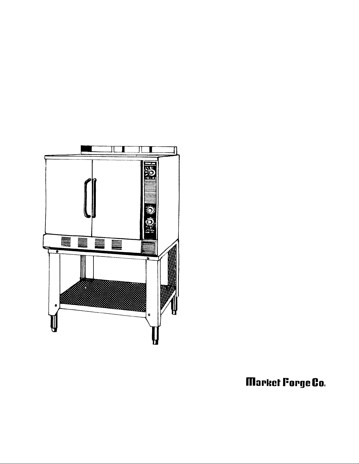
High Efficiency Gas Convection Oven
2500 HEC
2700 HEC
2592 HEC
2792 HEC
Addendum to S-2207, for ovens
equipped with Carborundum
Ignition Systems.
MA 02149
Tel. (617) 387-4100, Telex 94-9414, Cable MAFORCO
Facsimiled 617-387-4456
Page 2

TABLE OF CONTENTS
Paragraph Page Paragraph Page
SECTION 1 INTRODUCTION SECTION 3 MAINTENANCE & PARTS LIST
1.1 Description 1-1 3.1 General 3-1
1.2 Basic Functioning 1-1 3.2 Repair and Replacement 3-1
1.3 Service 1-1 3.3 Direct Spark to Igniter System
SECTION 2 TROUBLE-SHOOTING
2.1 General 2-1
2.2 Electrical Fault Isolation 2-1
Conversion 3-1
3.4 Illustrated Parts List 3-2
17-0400 ii
Page 3

SECTION 1 INTRODUCTION
1-1
17 0400
This service and parts addendum to High Efficiency Gas Convection Oven Service & Parts Manual contains descriptive
information, trouble shooting and maintenance information, and parts identification for ovens equipped with igniter ignition
systems Only information pertinent to the igniter system is contained in this addendum For details of the direct spark ignition
1.1 DESCRIPTION
High Efficiency Gas Convection Ovens having model suffix
' —HEC' are equipped with Silicon Carbide gas igniter
ignition systems manufactured by the Carborundum
Company in lieu of the standard direct spark ignition
system (model suffix '—HE') Igniter systems are incorporated in ovens used with LP or butane gas (Direct
spark systems are used primarily with natural gas )
1.2 BASIC FUNCTIONING
The oven with igniter ignition system operates in the same
manner as other Market Forge High Efficiency Gas Ovens
except for the method of initiating combustion of gas at the
burners With the power switch in the ON position, doors
closed and thermostat set, the circuit is completed to the
fan motor (which operates continuously) and the
igniter/thermal delay relay (T D R ) circuit is energized As
current begins to flow, the igniter starts to heat, causing its
resistance to decrease At an igniter temperature of
approximately 1,800°F, the resistance has decreased to
the point that current flowing through the T D R heater
raises the relay temperature to the operating level At the
operating level normally open contacts of the T D R are
closed, energizing the coil of the gas solenoid valve,
allowing gas to flow and ignition to occur
The entire ignition sequence is completed in 10 to 20
seconds, with combustion occurnng after a normal short
delay On initial combustion the igniter temperature
continues to rise until it reaches approximately 2,300°F , at
which its
system and all other oven assemblies, see Service & Parts Manual S 2207
resistance increases, effectively holding the circuit current
at the operating level of the T D R The igniter TDR and
gas valve circuits remain energized with TDR contacts
closed throughout the combustion cycle Only when the
oven temperature reaches the thermostat setting, causing
thermostat contacts to open, are the circuits interrupted
The complete ignition/combustion duty cycle is completed
repeatedly as required by the thermostat control
All other oven operation is as described in the Service &
Parts Manual for the High Efficiency Gas Convection
Oven
1.3 SERVICE
Should repairs be required, a network of authorized
service agencies is available to assist with prompt service
A current Directory of Authorized Service Agencies and
service assistance may be obtained by contacting
Product Service Department
Market Forge
35 Garvey Street
Everett, Massachusetts 02149
Tel (617)387-4100
Product Service Department Market Forge Canada, Ltd
1375 Aimco Boulevard, Unit 5 Mississauga, Ontario,
Canada L4W 1 B5 Tel (416)621-9252
The model and serial numbers must be referenced when
corresponding with Market Forge
Page 4

SECTION 3 MAINTENANCE & PARTS LIST
3.1 GENERAL
This section contains corrective maintenance
and parts identification information for the igniter
ignition system included in all "HEC" suffix gas
convection ovens For details of other subassemblies
and maintenance procedures, see Service & Parts
Manual, form number S-2207
3.2 REPAIR AND REPLACEMENT
Figures 3-1 and 3-2 include igniter system
assemblies together with a listing of replaceable parts.
Reference is made to these as well as illustrations in
form S-2207, Section 7 in the following procedures.
3.2.1. REPAIR AND REPLACEMENT
3.2.1. Igniter Removal
1. Remove bottom front louvered trim by sliding
forward off frame
2. Remove #8-32 x 1/2 screws securing control panel
to oven front and carefully pull panel forward to the
extent of free-play in connecting wiring.
WARNING
Avoid electrical shock by shutting off incoming
electrical service to the oven Exposed
terminals carry 120 volts.
3. Remove the two phillips head screws (figure
3-1, 16) which fasten the combustion box
manifold shield to the burner pan and lift
shield out.
4. Disconnect igniter leads #44 and #47 by twisting
off wire nuts. (See figure 2-1, 2-2, or 2-3).
5. Remove two #8 x 3/8 screws (41) from igniter
mounting flange and take igniter (40) out
6. Inspect and replace igniter as required and
reassemble in reverse of above.
3.2.2 Thermal Delay Relay Removal
The relay is a pin-mounted vacuum tube
located behind the control panel To access for
replacement and testing remove the control panel
as described in paragraph 321, step 2 The relay is
mounted in a socket base attached to support
bracket (figure 3-2, 5) By sliding shield (4) up off
the socket, the relay (3) is exposed for removal
3.3 Direct Spark to Igniter
System Conversion
Ovens equipped with Fenwal direct spark
ignition systems may be converted to the
Carborundum system when required A conversion
kit (part number 99-4698) containing all required
parts is available for this purpose
3.4 Illustrated Parts List
A complete listing of all replaceable parts of
the Carborundum ignition system for the High
Efficiency Gas Convection Oven is included in
Tables 2-1 and 2-2. Each parts list contains the
figure index number, the Market Forge part
number and an abbreviated description.
Orders for repair parts should be directed to the
nearest authorized parts distributor and should
include the part number, description as well as the
serial number and model number of the oven.
3-1
Page 5

HIGH
EFF|CIFN( Y
(
ONVFI [ION OVI N H.r.NIIFH
Figure
3-1
Gas Burner and Mainiold Assembly
IGNITION ADDENDUM
Page 6

MAINTENANCE
&
PARTS LIST
3-3
FIG. 3-1
ITEM NO.
PART NO. DESCRIPTION
1 10-7694 Gas Valve - Magnetic Solenoid
2 10-8225 Pressure Regulator
3 99-4424 Cross & Bracket Ass'y
4 10-3258 Gas Burner
5 99-3968 Manifold Ass'y
6 99-4349 Burner Pan Ass'y (33" Standard Oven)
6 a 99-4366 Burner Pan Ass'y (39" Deep Oven)
7 10-2400 Washer 1/4 Plain
8 10-2330 Hex Nut 8-32
9 10-2518 Lockwasher #8
10 99-4355 End Seal — Manifold Shield Ass'y
11 10-1804 Hex Hd Screw 1/4 - 20 x 5/8" Ig
12 10-1722 Screw Mach Rd Hd #6-32 x 3/8" Ig , (Fenwal system only)
13 10-2347 Speednut
14 10-1956 Phill Truss Hd Scr Type "A" #8-32
15 99-4358 Support Clip — Electrode Wires
16 10-1954 Phill Rd Hd Mach Scr #8-32 x1 5/8
17 99-4542 Manifold Shield Ass'y
18 10-1735 Phill Rd Hd Sheet Scr 3/8 Ig
19 10-1735 Phill Rd Hd Sheet Scr 3/8" Ig
20 99-4356 Bottom Seal — Manifold Shield Ass'y
21 10-1855 Pan Hd Scr Type "F" 8-32 x 3/8" Ig
22 10-3366 Burner Orifice #49 ( 078) Natural Gas
23 10-3367 Burner Orifice #56 ( 465) Propane
24 10-8226 Burner Orifice #57 ( 043) Butane
25 10-8351 Ignition Electrode, Fenwal
26 99-3925 Flame Baffle Ass'y (33" Standard Oven)
26 a 99-3927 Flame Baffle Ass'y (39" Deep Oven)
27 10-1954 Pan Hd Mach Scr #8-32 x 3/8"
28 10-2330 Washer #8
29 10-2408 Hex Nut #8-32
30 99-3564 Support Bracket
31 99-4362 Front Support Clips - Flame Baffle
32 10-1761 Truss Hd Mach Scr #8-32 x 3/8
33 10-2811 Street Elbow 90° M I 1/2
34 10-2810 Close Nipple B I 1/2"
35 10-3332 Union M I 1/2
36 10-2876 Reducing Coupling M I 3/4-1/2
37 99-4359 Retaining Clip — Electrode Wires
38 99-4469 Gas Burner With Electrode Bracket, (Fenwal system only)
39 99-4342 Gas Burner with Igniter Bracket, (Carborundum system only)
40 10-8259 Igniter, Carborundum(Model #420 GRS)
41 10-1855 Screw, Pan Hd , #8-32 x 3/8 (Carborundum system only)
42 99-4541 Adapter Enclosure
17 0400
Page 7

HIGH EFFICIENCY CONVECTION OVEN IGNITER
IGNITION ADDENDUM
7-0400
Figure 3-2 Temperature Delay Relay Assembly
FIG. 3-2
ITEM NO.
PART NO. DESCRIPTION
1 99-3537 Socket Base with connect, wires
2 10-9179 Screw, pan hd., #4-40 x 5/16" Ig.
3 10-8262 Relay, temperature delay
4 10-8261 Shield, relay
5 99-4454 Support Bracket
6 10-0265 Bushing, Heyco SB-750-9
7 99-4538 Nameplate, control panel (not shown)
Page 8

SECTION 2 TROUBLE-SHOOTING
2.1 GENERAL
This section contains trouble-shooting information to
assist service personnel in locating the general
source of problems which may occur with the model
"—HEC" suffix High Efficiency Gas Convection
Oven It is recommended that local authorized
service be obtained for assistance in completing
trouble shooting procedures
Table 2-1 serves as a general guide to troubleshooting Before attempting to utilize this
information, service personnel should be thoroughly
familiar with the operating instructions and the
function of all controls in Operator's Manual, form
number S-2206
TABLE 2-1 GENERAL TROUBLE-SHOOTING GUIDE
2.2 ELECTRICAL FAULT ISOLATION
Correction of an electrical failure first requires
isolation of the fault to a single circuit or
component In most cases the nature of the failure
and its effect on oven operation will be sufficient
to isolate it to one or more circuit elements Table
2 2 is provided as a guide for isolating electrical
faults which may occur in operation of the oven
equipped with igniter ignition system Wiring
Diagrams Figure 2 1 2-2 and 2-3 are provided for
locating the source of electrical failures
PROBLEM
Probable Cause
1. CONVECTOR FAN FAILS TO OPERATE
a. Power to oven is off Locate external circuit breaker for
b. Motor reset circuit breaker open Press MOTOR RESET button
c. Right oven door open Close door
d. ON-OFF switch off Place in ON position
e. Faulty motor reset, power switch, Test each component and connecting wiring
door switch, fan motor or wiring Replace as required
2. IGNITER NOT GLOWING, FAN OPERATING
a. Thermostat control not set Turn dial to required temperature setting
b. Faulty temperature delay relay Replace relay
c. Faulty igniter Replace igniter
d. Damaged or loose wiring Trace all wiring and check that all connections
3. GAS BURNERS FAIL TO IGNITE WITH IGNITER GLOWING
a. External gas supply shut -off closed Open valve
b. Gas solenoid valve fails in closed
position
Remedy
power and place in ON position
are secure
Replace valve
2- 1 17 0400
Page 9

TABLE 2-1 GENERAL TROUBLE-SHOOTING GUIDE (CONT )
4.
ERRATIC OVEN TEMPERATURE
PROBLEM
Probable Cause
3. GAS BURNERS FAIL TO IGNITE WITH IGNITER GLOWING (CONT'D)
c. Faulty temperature delay relay Replace relay
d. Damaged or loose wiring Trace all wiring and check that connections
are secure
a. Faulty thermostat operation Recalibrate or replace as required See
Remedy
Service & Parts Manual, form number
S-2207, subsection 632
TABLE 2-2 ELECTRICAL FAULT ISOLATION GUIDE
FAILURE FAULT LOCATION
1. Fan will not operate a. Incoming power
2. Igniter will not light with fan a. Thermostat control
operating b. Temperature delay relay
3. Gas burners will not operate with a. Incoming gas supply off
igniter glowing b. Temperature delay relay
4. Intermittent operation of burners a. Thermostat malfunction
5. Indicator light off, (system operating) a. Indicator light
b. Motor reset open
c. ON-OFF switch
d. Door switch
e. Wiring
f . Fan motor
c. Igniter
d. Wiring
c. Gas solenoid valve
d. Wiring
b. Temperature delay relay
c. Wiring
b. Wiring
Page 10

TROUBLE SHOOTING
Figure 2-1 Wiring Diagram — Igniter System, 115 volt, 60 Hz
Page 11

HIGH EFFICIENCY CONVECTION OVEN IGNITER
IGNITION ADDENDUM
Figure 2-2 Wiring Diagram — Igniter System, 220-240 volt, 50/60 Hz
Page 12

Figure 2-3 Wiring Diagram — Igniter System 700 Volt, 50/60 Hz, 2 wire
 Loading...