

Market Forge 2500HE Service Manual
SERVICE & PARTS MANUAL
Models:
2500 HE
2700 HE
2592 HE
High Efficiency Gas Convection Oven
2792 HE
MARKET FORGE industries Inc
Employee Owned Company
World Headquarters: 35 Garvey Street, Everett, MA 02149
Tel. (617) 387-4100, Fax 800-227-2659 (U.S. Except MA) or (617) 387-4456 (In MA)
Form No. S-2207 6/94 Printed in U.S.A.

TABLE OF CONTENTS
Paragraph Page Paragraph Page
SECTION 1 INTRODUCTION
11 Description 1-1 51 General 5-1
12 Basic Functioning 1-1 52 Trouble-Shooting Guide 5-1
13 Service 1-1 53 Electrical Fault Isolation 5-3
SECTION 2 INSTALLATION
21 Receiving 2-1 541 Incoming Power 5-3
22 Assembly 2-1 542 Electrical Inspection 5-3
221 Oven on 7" (178mm} Stand 2-1 543 Direct Spark Ignition System 5-3
222 Oven on Modular Base 2-1 544 Thermostatic Control 5-5
223 Oven on 28" (711mm} Open Stand 2-1 545 Solenoid Gas Valve 5-5
224 Stack Oven on 7" (178mm} Stand 2-1 546 Wiring 5-5
23 Gas Connection 2-3 547 Buzzer Relay 5-5
231 Placement 2-3
232 Materials 2-3 SECTION 6 MAINTENANCE
233 Connection 2-3 61 General 6-1
234 Gas Leak Test 2-3 62 Preventive Maintenance 6-1
24 Electrical Connection 2-3 63 Adjustment Procedures 6-1
25 Ventilation 2-5 631 Oven Door Adjustments 6-1
251 Flue Deflector Installation 2-5 632 Thermostat Calibration 6-2
26 Installation Check-Out 2-5 64 Repair and Replacement 6-2
261 Initial Control Settings 2-5 641 Control Panel Removal 6-2
262 Oven Check-Out 2-5 642 Right Side Panel Removal 6-3
263 Shut -Down Procedure 2-6 643 Fan Blade Removal 6-3
SECTION 3 OPERATION
31 Operating Controls and Indicators 3-1 646 Gas Valve Removal 6-4
32 Operating Procedures 3-1 647 Thermostat Removal 6-4
321 Preheating 3-1 648 Ignition Control Board Removal 6-4
322 Cooking 3-1 65 Adjustments and Operational
SECTION 4 PRINCIPLES OF OPERATION
41 General 4-1 652 Regulator Adjustment 6-4
42 Combustion/Vent Circuits 4-1
43 Electrical Circuits 4-2 SECTION 7 ILLUSTRATED PARTS LISTS
431 Control Circuit Components 4-2 71 General 7-1
SECTION 5 TROUBLE -SHOOTING
54 Electrical Trouble-Shooting
Procedures 5-3
644 Burner Pan Removal 6-3
645 Electrode Removal 6-4
Checks of Burner Components 6-4
651 Gas Burners 6-4
72 Ordering Information 7-1
73 Index of Illustrated Parts Lists 7-1

LIST OF ILLUSTRATIONS
Figure
Page
SECTION 1 INTRODUCTION
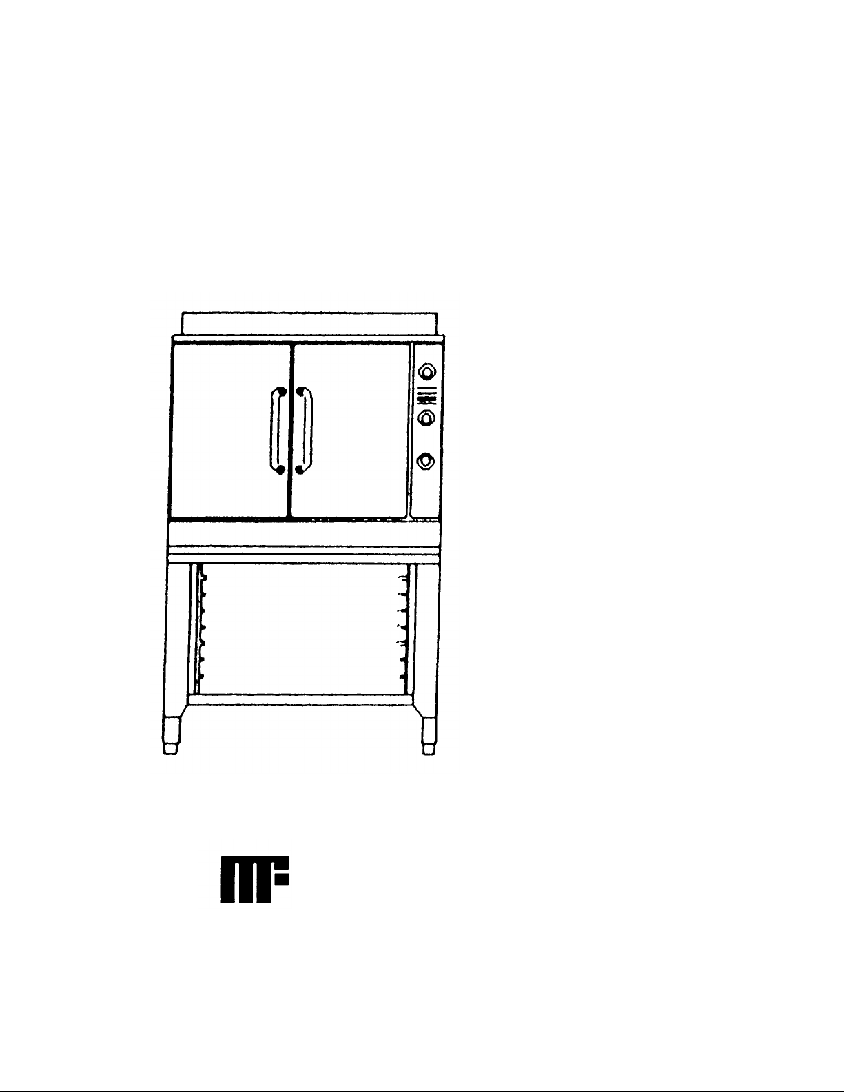
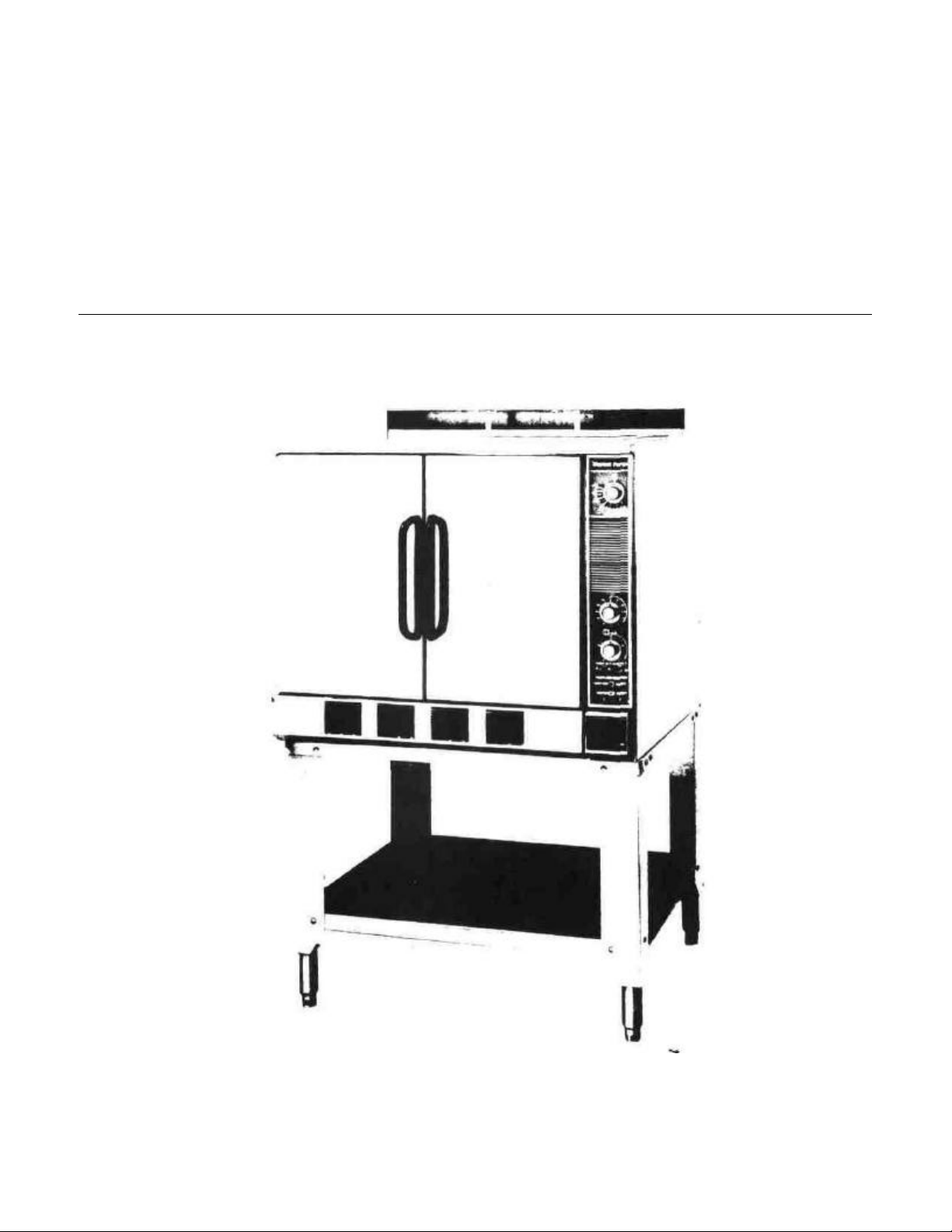
1-1 High Efficiency Gas Convection Oven
SECTION 2 INSTALLATION
2-1 7" Stand 2-1
2-2 28" Stand 2-2
2-3 Stacked Ovens 2-2
2-4 Service Connections 2-4
SECTION 3 OPERATION
3-1 Control Panel 3-2
SECTION 4 PRINCIPLES OF OPERATION
4-1 Cutaway Oven 4-1
4-2 Schematic Control Circuits 4-2
1-2
LIST OF TABLES
Figure
SECTION 5 TROUBLE -SHOOTING
5-1 Wiring Diagram 5-3
5-2 Flame Current Meter Placement 5-4
SECTION 6 MAINTENANCE
6 1 Blower Guard 6-1
6-2 Wheel Puller Kit 6-3
6-3 Air Shutter Adjustment 6-5
SECTION 7 ILLUSTRATED PARTS LISTS
7-1 Frame & Cabinet Assembly 7-2
7-2 Manifold & Burner Pan Assembly 7-4
7-3 Door Assembly 7-6
7-4 Control Panel Assembly 7-8
7-5 Ignition Control Board Assembly 7-10
Page
Table Page Table
SECTION 3 OPERATION SECTION 5 TROUBLE-SHOOTING
3-1 Control Panel Components 3-3 5-1 General Trouble-Shooting Guide 5-1
5-2 Electrical Fault Isolation Guide 5-2
Page

SECTION 1 INTRODUCTION
This service and parts manual contains general information, installation, operation, principles of operation, trouble-
shooting, and maintenance information for the Market Forge High Efficiency Gas Convection Oven Also included
are parts lists, in which each replaceable part is identified and shown in an accompanying exploded view
1.1 DESCRIPTION
The Market Forge Model HE Gas Convection
Oven is a gas fired, pilotless, direct-spark-igni-tion
system convection oven The unit is designed to
operate from a natural, propane, or butane gas
supply when equipped with appropriate gas orifices
It consists of a heavily insulated cooking
compartment fitted with a convector fan and heated
by a gas burner system designed to achieve optimal
efficiency from the fuel burned All oven controls are
located on a recessed panel on the right front of the
oven as seen from the front
The major assemblies of the HE oven are the
stainless steel or baked enamel finish cabinet
enclosure, solid doors, stainless steel cooking
compartment with nine shelf supports, convector
fan, pressure regulator and gas valve manifold
assembly, burner box assembly consisting of gas
burners, orifices, and direct spark ignition elec trode
The control panel assembly includes the thermostat,
electronic ignition control board, 60-minute and 5hour mechanical timers, red indicator light, ON-OFF
power switch, warning buzzer, and ignition and
motor reset switches
The unit is available in a variety of mounting
configurations 7" (178mm) counter stand, 28"
(711mm) modular base, open stand on legs with
shelf and optional storage rack, or stacked on top of
another HE oven with the bottom unit on 6" (152mm)
stainless steel legs
1.2 BASIC FUNCTIONING
The HE oven becomes operational when the
power switch is placed in the ON position, doors are
closed, and thermostat set Electronic ignition
activates, energizing the burner electrodes and
opening the gas valve (The fan operates continuously
with power on and doors closed, regardless of
thermostat setting ) Gas passes through the regulator
and valve to the burners, where it is ignited by the
sparking of the elec trodes The resulting flame heats a
flame baffle plate mounted under the cooking
chamber, which in turn heats the chamber The fan
circulates air uniformly through the chamber When the
chamber reaches the preset temperature, the
thermostat contacts open and the gas valve closes
When the temperature drops enough to close the
contacts, the ignition system reactivates Any number
of such cycles might occur during the cooking time If
for any reason the burners fail to ignite, the system
automatically closes the gas valve Should the burners
go out prematurely, the system will automatically activate the ignition electrodes, and if flame is not
established the system will shut down and close the
gas valve
1.3 SERVICE
Required service, both preventive and corrective,
is explained in Section 6 Should repairs be required, a
network of authorized agencies is
available to assist with prompt service. A current directory
of Authorized Service Agencies may be obtained by
contacting:
Product Service Department
Market Forge
35 Garvey Street
Everett, Massachusetts 02149
Telephone (617) 387-4100
Product Service Department
Market Forge Canada Ltd.
1375 Aimco Blvd., Unit 5
Mississauga, Ontario, Canada L4W 1B5
Telephone (416) 621-9252
The model and serial numbers must be referenced when
corresponding with Market Forge. The data plate with serial
number is located on the center of the bottom front trim
ledge.
Figure 1-1. High Efficiency Gas Convection Oven on Optional Stand
SECTION 2 INSTALLATION
2.1 RECEIVING
The oven is shipped bolted to a skid and cov ered by
a carton which is nailed to the skid, these must be
carefully removed prior to installation DO NOT AT ANY
TIME LAY THE OVEN ON ITS TOP, SIDE, OR FRONT
TO DO SO MAY DAMAGE THE EQUIPMENT AND
INVALIDATE THE WARRANTY
2.2 ASSEMBLY
Set-up and assembly procedures for the various oven
configurations are described in the following paragraphs
2.2.1 Oven on 7" (178mm) Stand
1. Screw legs (Figure 2-1, #4) into top frame assembly
(1)
2. Place into position front and rearchannel assembly
(2) and side angles (3) These items are loose parts
and are tied together with mounting of oven to stand
3. For single oven, mount oven to stand using four
3/8-16 x 3/4 Ig hex head cap screws and four 3/8
plain washers provided
4. For stacked oven, proceed to paragraph 2 2 4
5. For single oven, proceed to subsection 2 3
2.2.2 Oven on Modular Base
1. Screw adjustable feet into cabinet base
2. Mount oven to base using four 3/8- 16 x 3/4 Ig
hex head cap screws and four % plain washers
provided
3. Proceed to subsection 2 3
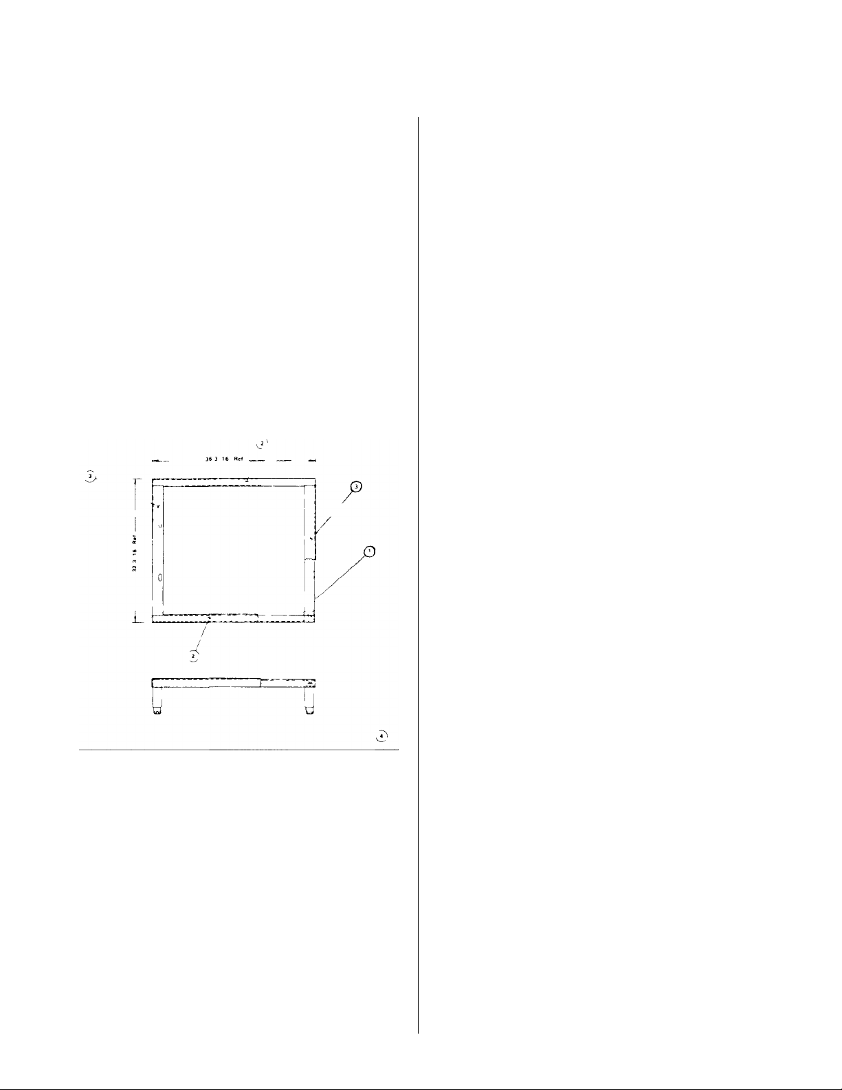
2.2.3 Oven on 28" (711mm) Open Stand
1. Place top frame (Figure 2-2, #2) upside down on
a clean smooth surface
2. Place into position front and rear angle as semblies (8) (stainless only) and legs (1)
3. Align holes in legs, frame, and angle assemblies
Secure using carriage bolts, lockwash-ers, and
nuts provided (5,6,7)
4. Align holes in shelf (3) with leg holes and secure
using hardware (5,6,7)
5. Screw adjustable feet (4) into stand legs
6. Install four clips for oven rack support inside top
frame using hardware (5,6,7) optional
7. Place stand in upright position Install rack
support, if supplied, inserting ends through holes
in clips and shelf
8. Mount oven to stand using four ¾-16 x 3/4 Ig
hex head cap screws and four 3/8 plain washers
provided
9. Proceed to subsection 2. 3
Figure 2-1. 7" (178mm) Stand
2.2.4 Stack ovens on 7" (178mm) stand
See 2.2.1 for stand assembly and proceed as
Follows:
1. Remove rear panels from both ovens by
removing 14 Phillips head screws from each
rear panel.
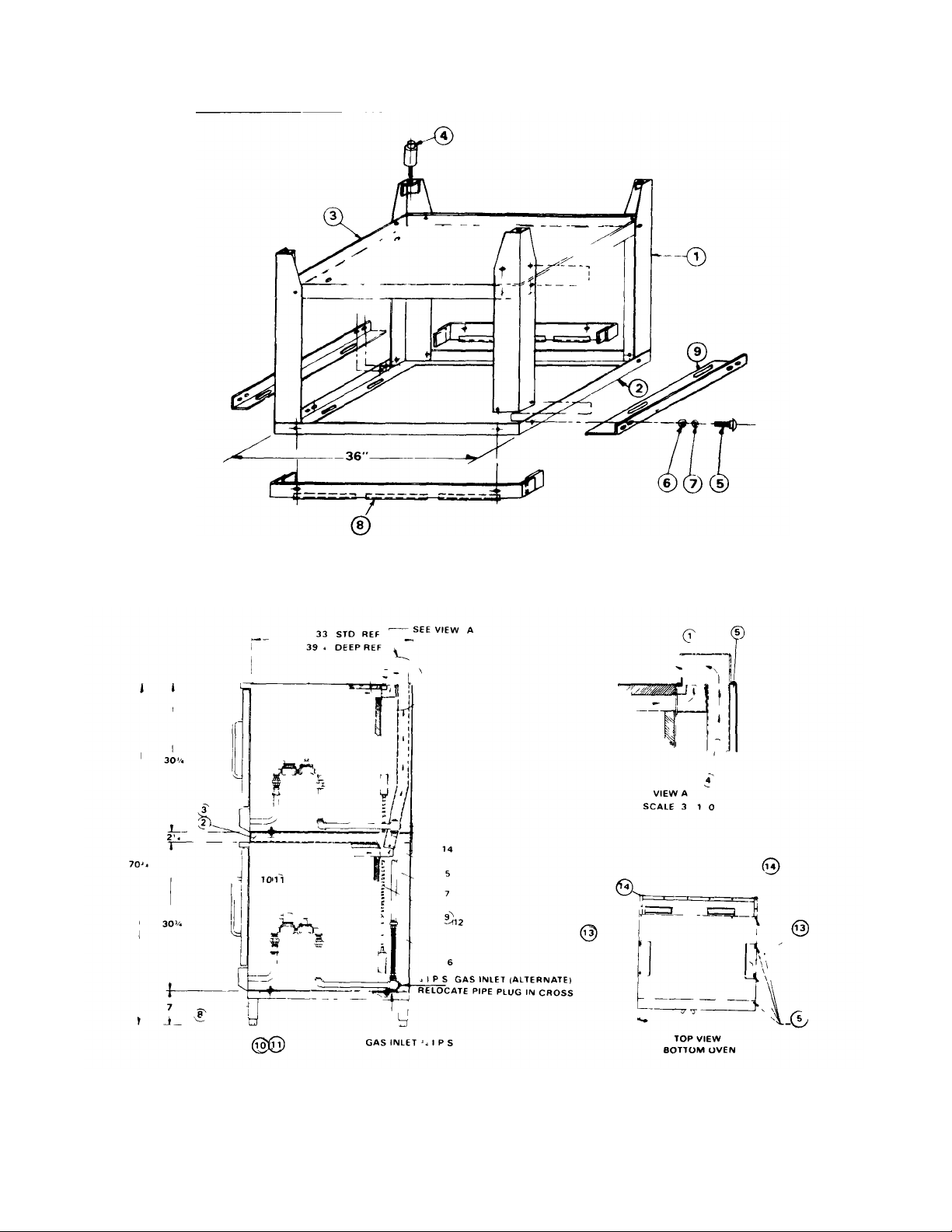
Figure 2-2 28" (711mmi Open Stand (Inverted for Assembly)
Figure 2-3 Stacked Ovens

2. Tilt ovens onto left sides as seen from front to
access bottoms DO NOT AT ANY TIME LAY THE
OVENS DOWN ON TOPS, RIGHT SIDES, OR
FRONTS. TO DO SO MAY DAMAGE THE
EQUIPMENT AND INVALIDATE THE WARRANTY
3. Install 7" (178mm} stand to bottom oven using
hardware (Figure 2-3, #10, 11). Either oven may
serve as bottom oven. Stand is 32" (813} front to
back. When used with deep ovens, overhang may
be either front or back, as desired. (Recommended
overhang is in back )
4. Stand bottom oven upright, onto stand.
5. Install top retaining brackets (13) on top of bottom
oven by removing two screws from top panel, left
and right, as shown, and replacing through holes in
brackets.
6. Install spacer assembly (2 or 3) on bottom of top
oven using hardware (10, 11).
7. Stack top oven on bottom oven.
8. Attach long flue assemblies (4) to top and bottom
ovens. See Figure 2-3, view "A".
NOTE
If stacked ovens are adjacent to moisture producing
equipment (such as kettles or steam cookers) it is
necessary to seal the seam between the stacked ovens
and the moisture producing equipment to prevent
condensation from entering the control section of the
bottom oven Silicone synthetic rubber is recommended
for a sealant
rear wall if adjoining wall is combustible Allow 6" (152mm}
clearance on right from another gas fired heat generating
piece of equipment, unless the equipment is another Market
Forge High Efficiency Oven, in which case no spacinq is
needed.
2.3.2 Materials
Use new pipe 3/4" (19mm} IP S properly reamed, free from
chips, and threaded to the proper length. If pipe dope is
used, apply a moderate amount, leaving two end threads
bare If Teflon tape is used, apply one and one-half turns,
leave ing the two end threads bare
2.3.3 Connection
Connect the gas line into the oven bottom at the right rear as
seen from the front, or alternate connection right rear back.
See Figure 2-4 For stacked ovens, connect gas pipe lines
between ovens using 3/4" (19mm} I.P.S. flexible connector
(Figure 2-3, #6) and 3/4" (19mm} I.P.S. x 20 1/4 tg nipple
(7). Install 3/4" (19mm} external gas supply shut -off valve
(furnished with unit) in an easily accessible location.
NOTE:
MANIFOLD PRESSURE MUST BE 4.0" (102mm} WATER
COLUMN FOR NATURAL GAS OVENS AND 10.0"
(254mm} FOR LP GAS OVENS SUPPLY PRESSURE
MUST BE AT LEAST 6.0" (152mm} FOR NATURAL GAS
AND 100" (254mm} FOR LP GAS. INSTALL PIPE PLUG IN
SIDE OF PIPE NOT BEING USED TO FEED GAS TO UNIT
2.3 GAS CONNECTION
This oven is factory adjusted for a gas consumption
rate of 60,000 BTU/hour. Read the nameplate on the
lower front access panel If this plate is marked for a
different gas than that being supplied, notify your dealer
immediately. DO NOT CONNECT GAS LINES Only a
qualified service technician should make the installation.
Installation must conform with the National Fuel Gas
Code ANSI Z223 1-1974, or CSAB1491 installation
codes, where applicable.
2.3.1 Placement
Allow 2" (51mm} clearance from side wall and
2.3.4 Gas Leak Test
Perform a gas leak test of all newly made joints, as well as
those leading to the main gas control valve. Check for leaks
using soap solution. DO NOT USE FLAME.
2.4 ELECTRICAL CONNECTION
Where applicable, installation must conform with
National Electrical Code ANSI C1-1975 or Canadian
Electrical Code C22 1, and/or local codes.
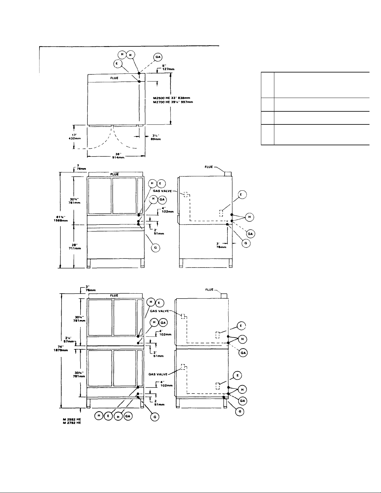
SERVICE CONNECTIONS
Hz.
1/2" 13mm conduit connection or equivalent
amps per oven Use wire suitable for at
Alternate
2.
Access to electrical junction box
GAS OPERATED
E
Electrical connection — 120 volt AC. 60
10
least 90°C
G 3/4" 19mm I.P.S Gas Connection Inlet,
Standard
GA 3/4" 19mm I.P.S Gas Connection Inlet,
H 1 3/4" 44mm dia. access holes for
1. Alternate gas supply connection GA

1. Connect the power supply wires to the junction
box at the right back of the oven Use wire
suitable for at least 90°C Ensure that hot wire
connects to terminal L1 and neutral wire to L2
2. For stacked ovens, connect power supply to
bottom oven junction box Install flexible conduit
assembly (Figure 2-3, #9 or 12) between top
and bottom junction boxes
3. Ground unit using ground lug in supply box
4. Replace rear panel(s)
5. For stacked ovens, add back retainer clips
(Figure 2-3, #14) to back of both units using
existing screws
2.5 VENTILATION
Proper ventilation is highly important for good
oven operation The use of a mechanical exhaust
system is ideal A properly designed unit will extend
approximately 4" to 6" (102-152mm) beyond all
sides of the oven unit In such instances the oven will
be equipped with a flue deflector, which is shipped
separate from the oven in the stand carton If the flue
outlet is to be connected directly to a chimney, then
a down draft diverter should be employed AT NO
TIME SHOULD A DAMPER BE INSTALLED IN THE
EXHAUST SYSTEM OF THIS OVEN
2.5.1 Flue Deflector Installation
To install deflector, remove back row of screws from
oven top panel Add flue deflector with open side
facing front, and replace screws For stacked ovens,
see Figure 2-3, view "A"
2.6 INSTALLATION CHECK-OUT
After the oven is completely assembled and
properly located with gas and electrical supplies
connected, the unit should be given a thorough
check-out before being put into operation Check-out
procedures for the oven are given in subsection 2 6
2 If the unit fails to perform as described, consult the
trouble shooting guides in section 5 for corrective
action
Before making this check-out, the operator must
be thoroughly familiar with the operating procedures
in Section 3, and with the function of
each control described in Table 3 1 Reference Figure
3-1 for identification of controls
2.6.1 Initial Control Settings
Power switch and thermostat dial are in OFF
position
2.6.2 Oven Check-Out
A final check of the controls and connections
should be made as follows
1. Make sure that the blower guard is properly
mounted See Figure 6-1
2. With a level on the oven shelves make sure that
the oven is level both front and back left and right
To adjust, turn feet in stand legs NOTE Be sure
wire shelf supports are in, not on, brackets
3. Make sure that gas and electrical supplies are
available to the unit
4. Set thermostat dial at 350°F
5. Place power switch in the ON position with doors
open
6. Close doors Indicator light should come on, fan
should come on and rotate clockwise (seen from
front) NOTE Buzzer may sound for an instant
a) If fan does not start, or starts and immediately
stops, press MOTOR RESET
b) If buzzer sounds, press IGNITION RESET
7. If fan still does not work or buzzer sounds again,
see Tables 5-1 and 5-2 for troubleshooting and
electrical fault isolation
8. Indicator light will remain on while oven is heating,
and go out when preset temperature is reached
During the heat -up period, some slight smoke or
fumes may result due to oil or grease on metal
surfaces This should cease after five minutes
9. During initial burner operation, observe flame
angle of each burner through the louvers on the
lower front panel If flames are not vertical, burners
may not be positioned properly, see subsection
6.4.4
10. After this check is completed, turn thermostat dial
and power switch to OFF position

2.6.3 Shut-Down Procedure
1. For daily shut -down, place thermostat dial
and power switch in OFF position.
2. For extended shut-down, place thermostat dial and
power switch in OFF position. Close external gas
supply shut -off valve. Leave doors ajar.

SECTION 3 OPERATION
3.1 OPERATING CONTROLS AND
INDICATORS
All the controls required to operate the oven are
listed in Table 3-1 with a short functional description
of each. Figure 3-1 shows the physical location of
each control and indicator.
3.2 OPERATING PROCEDURES
Before attempting to use the oven for cook ing,
be sure that proper gas and electrical connections
have been made, gas supply valve is open, and fan
guard properly mounted.
3.2.1 Preheating
1. Arrange shelf positions according to the item to
be cooked. Refer to Test Kitchen Bulletin #41
for correct positioning.
2. Place power switch in the ON position. Close
doors. Fan should come on and rotate clockwise. If not, depress the MOTOR RESET but ton. If fan still does not operate, consult Table 5-
1.
3. Set thermostat dial to desired temperature.
Indicator light should come on. Burners should
ignite. If not, buzzer will sound. Depress the
IGNITION RESET button. If burners still do not
ignite, consult Table 5-1.
4. Preheat to temperature and allow to cycle once
(indicator light on, off, on) to obtain
even temperature throughout oven Total time:
approximately 15 minutes
3.2.2 Cooking
The oven is ready for cooking use when the
indicator light goes off. The load should be adjacent to
the oven, so that doors will be open as short a time as
possible during loading.
1. Load oven. If using oven for long term roasting of
meats, fish, or poultry, place about a quart of
water in the oven in a suitable container or under
a trivet in the same pan as the food.
2. Close doors and set timer for desired cooking
time.
NOTE: Timer is for convenience only and does not
control oven operation. Bell will ring at end of
preset interval.
3. Unload oven and proceed as follows:
a) If oven is to be turned off, place thermostat
dial and power switch in the OFF position.
b) If oven temperature is to be lowered, set
thermostat to desired temperature. Close right
door and leave left door open. Fan will
continue to run. When light comes on, oven is
at lower temperature. Close left door. When
light goes off, oven is ready to use.
4. Place thermostat dial and power switch in OFF
position for daily shut -down. For extended shutdown, place dial and switch in OFF position,
close gas supply valve, and leave doors ajar.
3-1
 Loading...