


V-4224
PLAY IT SAFE!
OPERATION, MAINTENANCE
AND INSTALLATION MANUAL
FOR
VERTICAL RECYCLER BALER
V-4224
Marathon Equipment Co. OMI Manual No. 0011CE, Rev. 02/02
VERNON, AL - FAYETTE, AL
YERINGTON, NV - CLEARFIELD, PA
CE RATED MODEL

Introduction .................................................................. 1-1
EC Declaration of Conformity....................................... 1-2
Pre-Operating Instructions ....................................... 1-3
Controls ....................................................................... 1-4
Control Description ...................................................... 1-5
Operating Instructions
Making A Bale ................................................... 1-6
Bale Tie Off/Bale Eject ...................................... 1-7
Diagram ................................................. 1-8
Tie Slot Cleaning ......................................................... 1-9
Decals ......................................................................... 1-10
Decal Placement ......................................................... 1-11
Lock-Out & Tag-Out Instructions ............................. 2-1
Supporting Of Platen ................................................... 2-2
Periodic Maintenance .................................................. 2-3
Pressure Setting .......................................................... 2-4
Interlock Testing .......................................................... 2-5
Cylinder Removal And Rebuilding .............................. 2-6
Feed Gate Latch Adjustment ...................................... 2-7
Principles Of Operation ............................................... 2-8
Charts ......................................................................... 2-9
Panel Box .................................................................... 2-10
Power Unit ................................................................... 2-11
Electrical Schematic .................................................... 2-12
Hydraulic Schematic ................................................... 2-13
Parts List ..................................................................... 2-14
Recommended Oil ...................................................... 2-14
Motor Warranty ........................................................... 2-14
General Installation ..................................................... 3-1
Anchoring To Concrete Pad ........................................ 3-2
Electrical Installation ................................................... 3-3
Start-Up Instructions .................................................... 3-4
CONTENTS
Copyright © 2002 Marathon Equipment Company
SECTION 1 - Operation
SECTION 2 - Maintenance
SECTION 3 - Installation

1 OPERATION
INTRODUCTION
THANK YOU FOR PURCHASING A MARATHON VERTICAL BALER.
This product is designed to give you reliable service and superior performance for years
to come. To guarantee top performance and the safest operation of the baler, each
person involved in the operation, maintenance and installation of the baler should read
and thoroughly understand the instructions in this manual and follow all warnings.
The employer(s) involved in the operation, maintenance and installation of the baler
should read and understand the most current version of the following applicable
standards:
ANSI Standard No. Z245.5, “Safety Requirements For Baling Equipment”
A copy of this standard may be obtained from:
Environmental Industries Association
4301 Connecticut Avenue, N.W.
Suite 300
Washington, D.C. 20008
Telephone: 1-202-244-4700
OSHA 29 CFR, Part 1910.147, “The control of hazardous energy (lockout/tagout)”
IF YOU SHOULD NEED FURTHER ASSISTANCE, PLEASE CONTACT YOUR
DISTRIBUTOR. YOU WILL NEED TO PROVIDE THE BALER SERIAL
NUMBER, INSTALLATION DATE, AND ELECTRICAL SCHEMATIC NUMBER
TO YOUR DISTRIBUTOR.
IF YOU HAVE ANY SAFETY CONCERNS WITH THE EQUIPMENT, OR
NEED FURTHER INFORMATION, PLEASE CONTACT US AT:
Marathon Equipment Company
P.O. Box 1798
Vernon, Al 35592-1798
Attn: Field Service Department
1-800-633-8974
1-1
ALL SERVICE OR REPAIR PROCEDURES DESCRIBED IN THIS
MANUAL SHOULD BE PERFORMED BY AUTHORIZED, FULLY
TRAINED PERSONNEL.
Any service or repairs that go beyond the scope of this manual
should be performed by factory authorized personnel only.

EC DECLARATION OF CONFORMITY
The Supply of Machinery (Safety) Regulations 1992
Pursuant to The Council of The European Communities Directive 89/392/EEC, as amended by
91/36P/EEC
The Machine/Installation:
PRODUCT: V-4224 Vertical Recycler Baler
SERIAL NUMBER: As specified for EC export
YEAR OF MANUFACTURE: 2006
The above has been developed, designed and manufactured in accordance with the above relevant
statutory provisions by:
Marathon Equipment Company
950 County Road
Vernon AL, USA 35592
THIS DECLARATION WILL BECOME INVALID IF, FOLLOWING HAND OVER, THE
MACHINE/INSTALLATION IS ALTERED IN ANY WAY.
The following harmonized standards have been applied:
1991 EN 292/1 and EN 292/2, Safety of machines, devices and installations
1992 EN 418, Safety of Machinery, Emergency Stop Equipment, Functional Aspects.
Principals for Design
1992 EN 294, Safety distance to prevent access to danger zones
1993 EN 60 204-1, Safety of Machinery, Electrical Equipment of Machines
1993 EN 349, Safety of Machinery, Minimum Gaps to Avoid Crushing Parts of the
Human Body
1996 BS EN 982, Safety Requirements of fluid systems and components
1997 BS EN 1050, Safety of Machinery, Principles for Risk Assessment
1998 BS EN 953, Safety of machinery, Guards.
Technical documentation is available upon request.
The operating manual for the machine/installation is provided.
(* ) in the language of the country of manufacture
(*) in the national language of the user
P.O. Box 1798
Vernon, AL 35592-1798
800-633-8974
205-695-9105
http//www.marathonequipment.com
1-2
1 OPERATION
PRE-OPERATING INSTRUCTIONS
06-0045
460
VOLTS
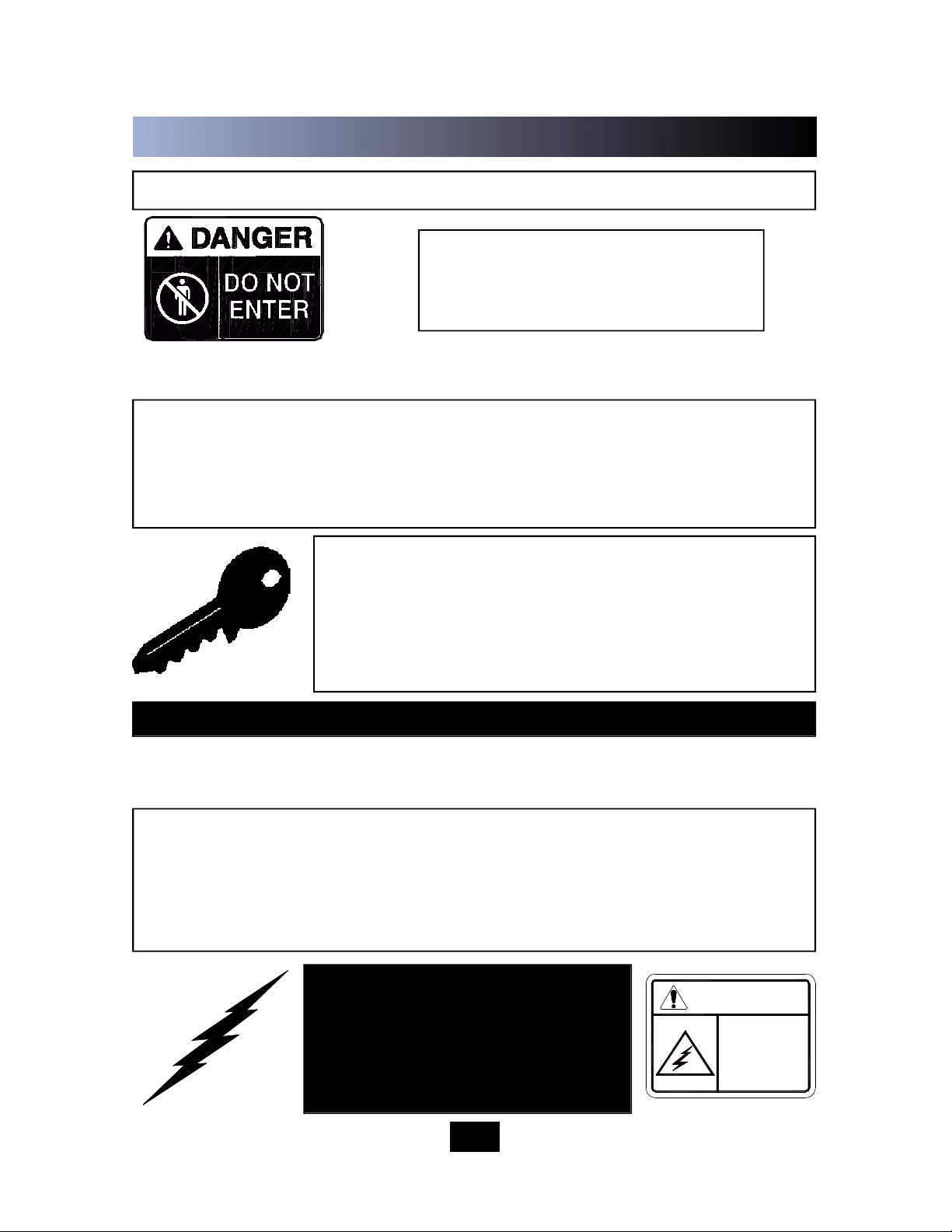
DANGER
NEVER ENTER ANY PART OF THE BALER UNLESS THE DISCONNECT
SWITCH HAS BEEN TURNED OFF AND PADLOCKED. Before starting the
baler, be sure no one is inside. Be certain that everyone is clear of all points of
operation and pinch point areas before starting. See Lock-Out & Ta g - O u t
instructions in the Maintenance section.
THE EMP LOY ER SH OUL D ALLOW ON LY
AUTHORIZED AND TRAINED PERSONNEL TO
OPERATE THIS BALER. This baler is equipped with
a key operated locking system. The key(s) should be
in the possession of only authorized personnel. Turn
off and remove key after use.
Pay close attention to the RED WARNING LIGHT on the control panel. If the light
is illuminated w hen the feed gate is raised, there is a malfunction of the
magnetic interlock system. IN THIS EVENT, DISCONTINUE USE OF THE BALER
AND LOCK-OUT & TAG-OUT THE BALER PER THE INSTRUCTIONS IN THE
MAINTENANCE S ECTION, PAGE 2-1. Perform necessary repairs before
continuing operation of the baler.
O N LY AUT H ORIZE D P ERSONN E L
SHOULD BE ALLOWED INSIDE THE
PA N E L B O X . The panel box contains
high voltage components. See Lock-Out
& Ta g -Out i n struc ti ons i n the
Maintenance section.
BE CERTAIN TURNBUCKLE AND LATCH IS FULLY LOCKED IN PLACE ON BALE
CHAMBER DOOR BEFORE STARTING BALER.
STAND CLEAR WHILE
BALER IS IN OPERATION.
WARNING: DO NOT OPERATE BALER UNTIL OPERATING INSTRUCTIONS ARE
THOROUGHLY UNDERSTOOD.
1-3
Federal regulation prohibits operation by persons under 18 years of age.
1 OPERATION
400
1 OPERATION
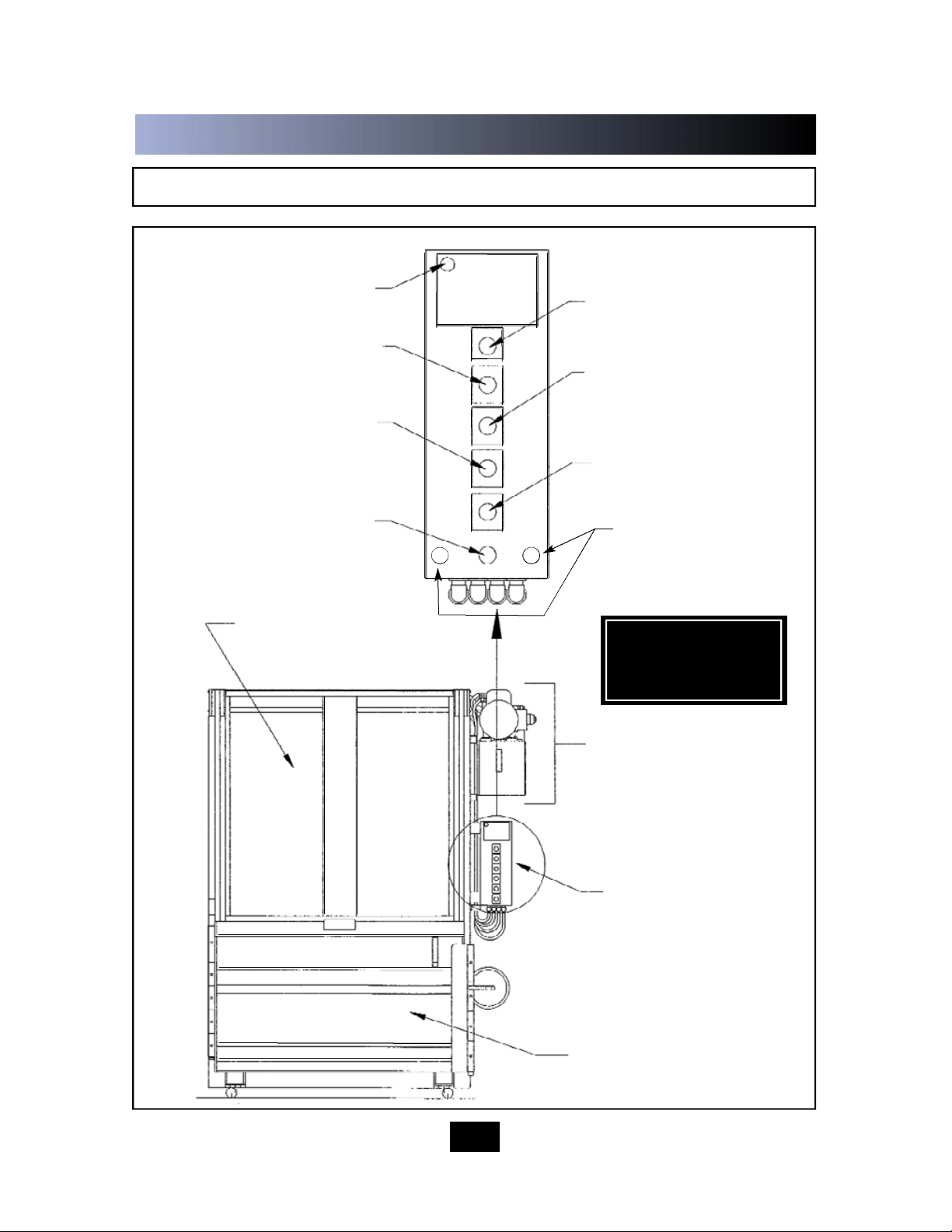
C O N T R O L S
1-4
MANUAL DOWN BUTTON
RED WARNING LIGHT
KEYED ON/OFF SWITCH
MANUAL UP BUTTON
BALE MADE LIGHT
EMERGENCY STOP BUTTON
CONTROL PANEL
FEED GATE
BALE DOOR
POWER UNIT
AUTOCYCLE BUTTON
*SEE CONTROL
DESCRIPTION ON
FOLLOWING PAGE
RESET INTERLOCK
OVERRIDE

1 OPERATION
CONTROL DESCRIPTION
1.
2.
3.
4.
5.
6.
7.
1-5
ON-OFF (Keyed Selector Switch)
Turning this switch to the ON position activates the other controls in the control panel. The
baler can not be operated unless the key is in the switch and the switch is in the ON
position. The purpose of this switch is to allow only authorized and trained personnel to
operate the baler. The key should be removed from the baler when not in use and should
stay in the possession of only responsible and trained personnel.
EMERGENCY STOP (Red Mushroom Head Pushbutton)
Depressing this button will stop the machine at any point in the cycle.
AUTOCYCLE (Green Pushbutton)
The AUTOCYCLE button can be used only when the feed gate and bale door are closed
and the keyswitch is in the ON position. Once depressed, the A U T OCYCLE button will
cause the platen to move to the fully down position and back to the fully raised position
(one complete cycle).
MANUAL UP (Black Pushbutton)
This button will only start the baler with the keyswitch in the ON position. Depressing this
button will raise the platen with the feed gate and bale door opened or closed. It is normally
used during bale ejection. It can also be used to interrupt the automatic cycle and raise the
platen should it become necessary. The MANUAL U P button is a “Hold To Run” control,
causing the baler to stop wh
en it is released. WA R N I N G : S T AY CLEAR OF MOVING
PARTS WHEN USING THE MANUAL UP BUTTON WITH THE FEED GATE OPEN.
MANUAL DOWN (Black Pushbutton)
This button will only start the baler with the keyswitch in the ON position. Depressing this
button will lower the platen only if the feed gate and bale door are closed. It can be used to
interrupt the automatic cycle and lower the platen should it become necessary. T h e
M A N U A L DOWN button is a “Hold To Run” control, causing the baler to stop when it is
released.
RED WARNING LIGHT
This light will warn the operator of a magnetic interlock switch malfunction. If the light is on,
and the feed gate is in the up position, there is a problem. Discontinue use of the baler.
Turn off the baler and Lock-out and Tag-out per the instructions on page 2-1. Then call a
qualified service person. The light SHOULD BE ON when the feed gate is in the down
position.
BALE MADE LIGHT
This light will come on if enough material has been compacted to make a complete bale.
IN CASE OF EMERGENCY:
Push the large red button to
STOP
OPERATING INSTRUCTIONS - MAKING A BALE
WA R N I N G : DO NOT O P E R A TE BALER UNTIL O P E R A TING INSTRUCTIONS A R E
UNDERSTOOD.
See page 1-4 for control panel layout.
1-6
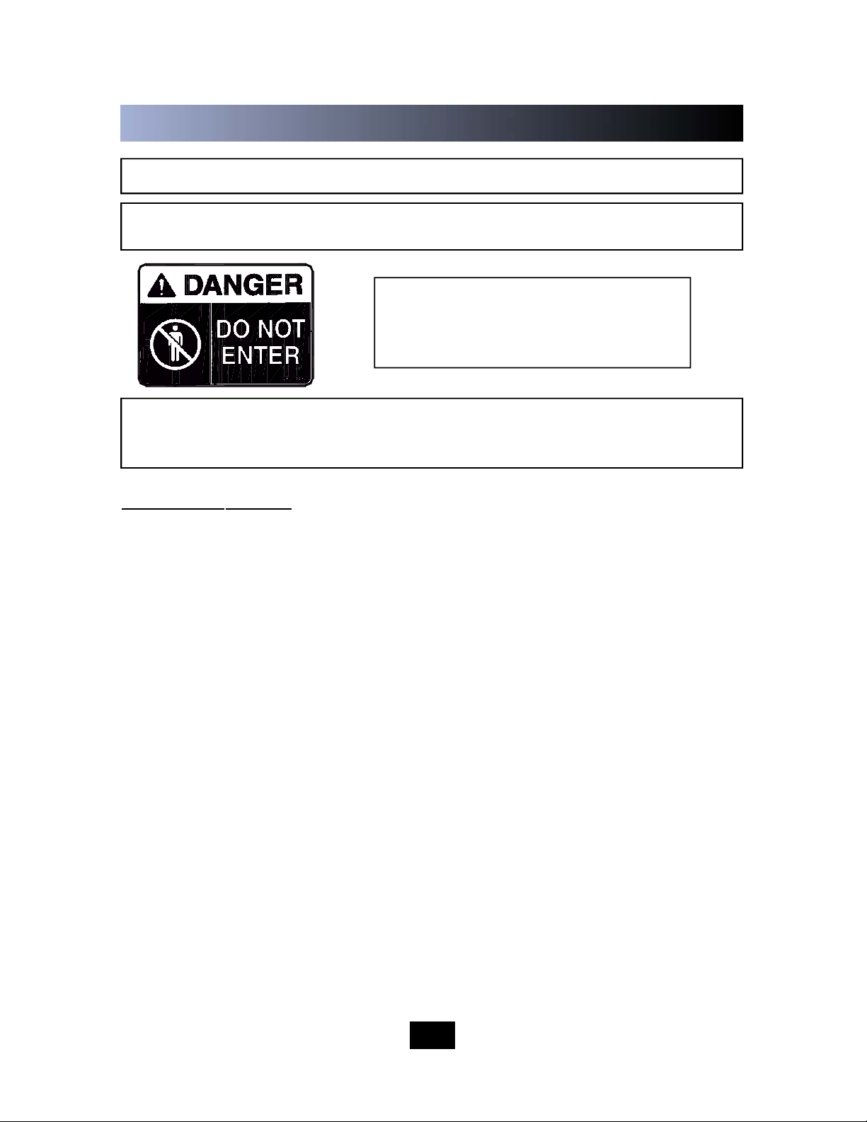
WARNING: Interloc ks and safety devices were installed on this u nit for your
p r o t e c t i o n . Never disable or bypass any interlock or safety device. Failure to
comply with this warning could result in serious injury or death.
TO MAKE A BALE :
1. Feed material into baler. If starting a new bale, place a large flat piece of
material flat on the baler floor. NOTE: Do not attempt to overfill the feed
chamber by forcing material into the chamber with the feed gate. This can cause
gate release malfunction and may damage baler.
2. Pull gate handle down to close feed gate. NOTE: Check red warning light
before closing feed gate. If gate is open and light is on, discontinue use of the
baler and call for service.
3. To start the baler, insert the key into the keyswitch and turn to the ON
position.
4. Press the AUTOCYCLE button. The platen will make a complete cycle down
and back up. When the platen is in the full up position, the feed gate will
automatically open and the motor will automatically shutdown.
5. Repeat steps 1 through 4 until the platen stops in the down position, and the
“BALE MADE” light comes on.
NOTE: In normal operation, the feed gate will be open when you walk up to
place material into the baler. For added security, the feed gate can be manually
closed after the AUTOCYCLE(S). To open the gate, you will have to insert the
key into the keyswitch and run the baler through a complete AUTOCYCLE.
1 OPERATION

OPERATING INSTRUCTIONS - BALE TIE OFF/BALE EJECT
1-7
When the “BALE MADE” light comes on it is time to tie off the bale and eject the bale
from the baler. See page 1-4 for control panel layout and location. See the following
page for a diagram of the following steps.
FOR BALE TIE OFF & BALE EJECT:
1. Press the MANUAL UP button until the platen is in the up position and the feed
gate raises.
2. Insert a large, flat piece of material across the top of the bale. With the platen in
the “up” position, make sure there is no cardboard, or other baled materials,
stuck between the back of the platen and the back wall of the baler. Remove any
materials found in this area.
3. Close feed gate and press the AUTOCYCLE button. The platen will move to the
down position and the BALE MADE light will come back on.
4. Release the bale chamber door latch on the side of baler and open the
bale chamber door all the way. Feed gate is closed but will raise when the bale
chamber door is opened.
5. CAUTION: Wear safety glasses and leather gloves during the following
operation: Facing the front of the bale, tie off bale by inserting bale ties (loop
end first) through the platen. Always insert bale ties through the tie slots in
the platen, first. Feed wire through until it comes out of the tie slot in the baler
floor. Tie off each tie. Bale ties should be tightened only hand tight, allowing for
bale expansion when released. See Diagram on Following Page.
6. Standing at the side, make sure all personnel are clear of the front of
the baler. Press and hold the MANUAL UP button until the bale ejects.
7. Remove bale from in front of baler. Close and latch the bale door completely.
Failure to close and latch the bale door completely may result in serious damage
to the bale ejector.
8. Close the feed gate, and press the AUTO CYCLE button and let the machine
run through a complete cycle to reset the bale ejector hook. When the feed gate
raises, the machine is ready to start the next bale.
NOTE: You can close the feed gate at this time if added security is required. To
open the gate you will have to run the baler through a complete AUTOCYCLE.
1 OPERATION
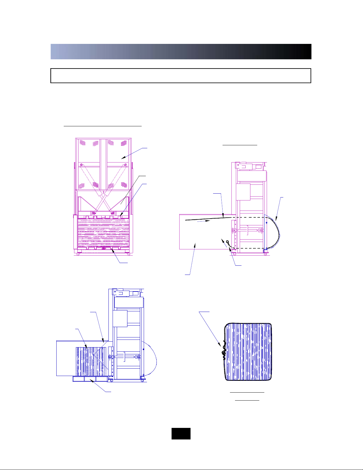
DIAGRAM - BALE TIE OFF/BALE EJECT
FRONT VIEW OF BALER
BALE TIE - TIGHTENED
HAND TIGHT
BALE DURING
EJECTION
PALLET OR BALE CART
RECOMMENDED FOR
SUPPORTING BALE
SIDE VIEW
BALE CHAMBER
DOOR OPENED
SIDE VIEW
- BALE
1-8
BALE TIES ENTER
THROUGH PLATEN
LOOPED END FIRST
BALE TIES EXIT
THROUGH FLOOR
EJECTED
BALE
BALE TIE SLOTS
PLATEN
BALE TIE SLOTS
FEED GATE OPENS
WHEN BALE DOOR
IS OPENED
BALE TIES
FOLLOW
WIRE
GUIDES
1 OPERATION
 Loading...