

Page 1

PLAY IT SAFE!
OPERATION, MAINTENANCE
AND INSTALLATION MANUAL
FOR
VERTICAL RECYCLER BALER
V-4224
Marathon Equipment Co. OMI Manual No. 0011CE, Rev. 02/02
VERNON, AL - FAYETTE, AL
YERINGTON, NV - CLEARFIELD, PA
CE RATED MODEL
Page 2

Introduction .................................................................. 1-1
EC Declaration of Conformity....................................... 1-2
Pre-Operating Instructions ....................................... 1-3
Controls ....................................................................... 1-4
Control Description ...................................................... 1-5
Operating Instructions
Making A Bale ................................................... 1-6
Bale Tie Off/Bale Eject ...................................... 1-7
Diagram ................................................. 1-8
Tie Slot Cleaning ......................................................... 1-9
Decals ......................................................................... 1-10
Decal Placement ......................................................... 1-11
Lock-Out & Tag-Out Instructions ............................. 2-1
Supporting Of Platen ................................................... 2-2
Periodic Maintenance .................................................. 2-3
Pressure Setting .......................................................... 2-4
Interlock Testing .......................................................... 2-5
Cylinder Removal And Rebuilding .............................. 2-6
Feed Gate Latch Adjustment ...................................... 2-7
Principles Of Operation ............................................... 2-8
Charts ......................................................................... 2-9
Panel Box .................................................................... 2-10
Power Unit ................................................................... 2-11
Electrical Schematic .................................................... 2-12
Hydraulic Schematic ................................................... 2-13
Parts List ..................................................................... 2-14
Recommended Oil ...................................................... 2-14
Motor Warranty ........................................................... 2-14
General Installation ..................................................... 3-1
Anchoring To Concrete Pad ........................................ 3-2
Electrical Installation ................................................... 3-3
Start-Up Instructions .................................................... 3-4
CONTENTS
Copyright © 2002 Marathon Equipment Company
SECTION 1 - Operation
SECTION 2 - Maintenance
SECTION 3 - Installation
Page 3

1 OPERATION
INTRODUCTION
THANK YOU FOR PURCHASING A MARATHON VERTICAL BALER.
This product is designed to give you reliable service and superior performance for years
to come. To guarantee top performance and the safest operation of the baler, each
person involved in the operation, maintenance and installation of the baler should read
and thoroughly understand the instructions in this manual and follow all warnings.
The employer(s) involved in the operation, maintenance and installation of the baler
should read and understand the most current version of the following applicable
standards:
ANSI Standard No. Z245.5, “Safety Requirements For Baling Equipment”
A copy of this standard may be obtained from:
Environmental Industries Association
4301 Connecticut Avenue, N.W.
Suite 300
Washington, D.C. 20008
Telephone: 1-202-244-4700
OSHA 29 CFR, Part 1910.147, “The control of hazardous energy (lockout/tagout)”
IF YOU SHOULD NEED FURTHER ASSISTANCE, PLEASE CONTACT YOUR
DISTRIBUTOR. YOU WILL NEED TO PROVIDE THE BALER SERIAL
NUMBER, INSTALLATION DATE, AND ELECTRICAL SCHEMATIC NUMBER
TO YOUR DISTRIBUTOR.
IF YOU HAVE ANY SAFETY CONCERNS WITH THE EQUIPMENT, OR
NEED FURTHER INFORMATION, PLEASE CONTACT US AT:
Marathon Equipment Company
P.O. Box 1798
Vernon, Al 35592-1798
Attn: Field Service Department
1-800-633-8974
1-1
ALL SERVICE OR REPAIR PROCEDURES DESCRIBED IN THIS
MANUAL SHOULD BE PERFORMED BY AUTHORIZED, FULLY
TRAINED PERSONNEL.
Any service or repairs that go beyond the scope of this manual
should be performed by factory authorized personnel only.
Page 4

EC DECLARATION OF CONFORMITY
The Supply of Machinery (Safety) Regulations 1992
Pursuant to The Council of The European Communities Directive 89/392/EEC, as amended by
91/36P/EEC
The Machine/Installation:
PRODUCT: V-4224 Vertical Recycler Baler
SERIAL NUMBER: As specified for EC export
YEAR OF MANUFACTURE: 2006
The above has been developed, designed and manufactured in accordance with the above relevant
statutory provisions by:
Marathon Equipment Company
950 County Road
Vernon AL, USA 35592
THIS DECLARATION WILL BECOME INVALID IF, FOLLOWING HAND OVER, THE
MACHINE/INSTALLATION IS ALTERED IN ANY WAY.
The following harmonized standards have been applied:
1991 EN 292/1 and EN 292/2, Safety of machines, devices and installations
1992 EN 418, Safety of Machinery, Emergency Stop Equipment, Functional Aspects.
Principals for Design
1992 EN 294, Safety distance to prevent access to danger zones
1993 EN 60 204-1, Safety of Machinery, Electrical Equipment of Machines
1993 EN 349, Safety of Machinery, Minimum Gaps to Avoid Crushing Parts of the
Human Body
1996 BS EN 982, Safety Requirements of fluid systems and components
1997 BS EN 1050, Safety of Machinery, Principles for Risk Assessment
1998 BS EN 953, Safety of machinery, Guards.
Technical documentation is available upon request.
The operating manual for the machine/installation is provided.
(* ) in the language of the country of manufacture
(*) in the national language of the user
P.O. Box 1798
Vernon, AL 35592-1798
800-633-8974
205-695-9105
http//www.marathonequipment.com
1-2
1 OPERATION
Page 5
PRE-OPERATING INSTRUCTIONS
06-0045
460
VOLTS
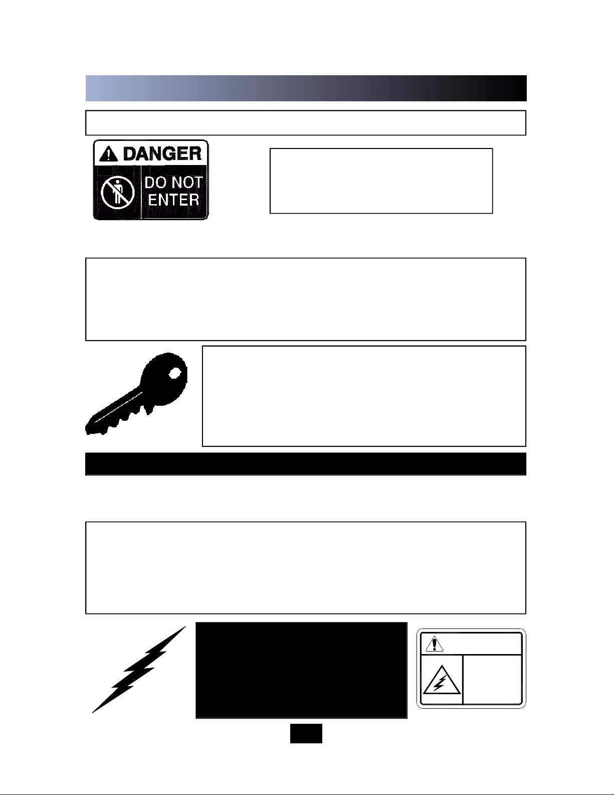
DANGER
NEVER ENTER ANY PART OF THE BALER UNLESS THE DISCONNECT
SWITCH HAS BEEN TURNED OFF AND PADLOCKED. Before starting the
baler, be sure no one is inside. Be certain that everyone is clear of all points of
operation and pinch point areas before starting. See Lock-Out & Ta g - O u t
instructions in the Maintenance section.
THE EMP LOY ER SH OUL D ALLOW ON LY
AUTHORIZED AND TRAINED PERSONNEL TO
OPERATE THIS BALER. This baler is equipped with
a key operated locking system. The key(s) should be
in the possession of only authorized personnel. Turn
off and remove key after use.
Pay close attention to the RED WARNING LIGHT on the control panel. If the light
is illuminated w hen the feed gate is raised, there is a malfunction of the
magnetic interlock system. IN THIS EVENT, DISCONTINUE USE OF THE BALER
AND LOCK-OUT & TAG-OUT THE BALER PER THE INSTRUCTIONS IN THE
MAINTENANCE S ECTION, PAGE 2-1. Perform necessary repairs before
continuing operation of the baler.
O N LY AUT H ORIZE D P ERSONN E L
SHOULD BE ALLOWED INSIDE THE
PA N E L B O X . The panel box contains
high voltage components. See Lock-Out
& Ta g -Out i n struc ti ons i n the
Maintenance section.
BE CERTAIN TURNBUCKLE AND LATCH IS FULLY LOCKED IN PLACE ON BALE
CHAMBER DOOR BEFORE STARTING BALER.
STAND CLEAR WHILE
BALER IS IN OPERATION.
WARNING: DO NOT OPERATE BALER UNTIL OPERATING INSTRUCTIONS ARE
THOROUGHLY UNDERSTOOD.
1-3
Federal regulation prohibits operation by persons under 18 years of age.
1 OPERATION
400
Page 6
1 OPERATION
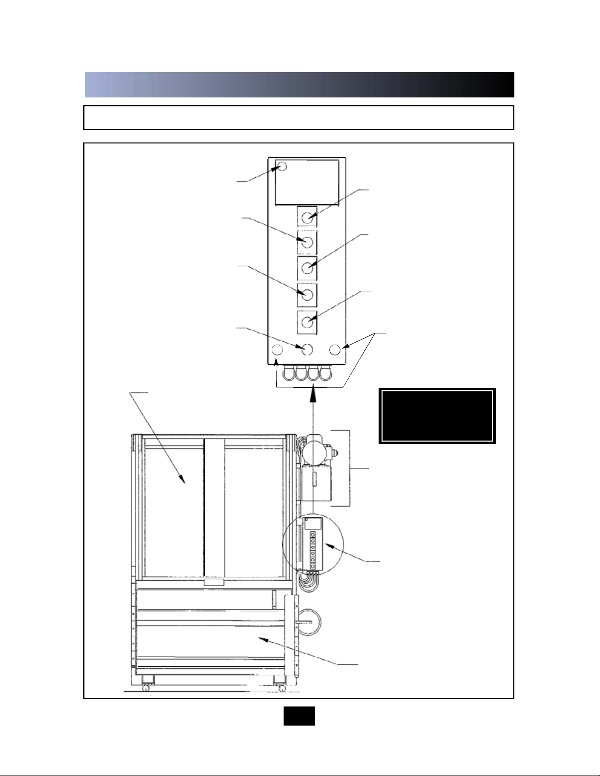
C O N T R O L S
1-4
MANUAL DOWN BUTTON
RED WARNING LIGHT
KEYED ON/OFF SWITCH
MANUAL UP BUTTON
BALE MADE LIGHT
EMERGENCY STOP BUTTON
CONTROL PANEL
FEED GATE
BALE DOOR
POWER UNIT
AUTOCYCLE BUTTON
*SEE CONTROL
DESCRIPTION ON
FOLLOWING PAGE
RESET INTERLOCK
OVERRIDE
Page 7

1 OPERATION
CONTROL DESCRIPTION
1.
2.
3.
4.
5.
6.
7.
1-5
ON-OFF (Keyed Selector Switch)
Turning this switch to the ON position activates the other controls in the control panel. The
baler can not be operated unless the key is in the switch and the switch is in the ON
position. The purpose of this switch is to allow only authorized and trained personnel to
operate the baler. The key should be removed from the baler when not in use and should
stay in the possession of only responsible and trained personnel.
EMERGENCY STOP (Red Mushroom Head Pushbutton)
Depressing this button will stop the machine at any point in the cycle.
AUTOCYCLE (Green Pushbutton)
The AUTOCYCLE button can be used only when the feed gate and bale door are closed
and the keyswitch is in the ON position. Once depressed, the A U T OCYCLE button will
cause the platen to move to the fully down position and back to the fully raised position
(one complete cycle).
MANUAL UP (Black Pushbutton)
This button will only start the baler with the keyswitch in the ON position. Depressing this
button will raise the platen with the feed gate and bale door opened or closed. It is normally
used during bale ejection. It can also be used to interrupt the automatic cycle and raise the
platen should it become necessary. The MANUAL U P button is a “Hold To Run” control,
causing the baler to stop wh
en it is released. WA R N I N G : S T AY CLEAR OF MOVING
PARTS WHEN USING THE MANUAL UP BUTTON WITH THE FEED GATE OPEN.
MANUAL DOWN (Black Pushbutton)
This button will only start the baler with the keyswitch in the ON position. Depressing this
button will lower the platen only if the feed gate and bale door are closed. It can be used to
interrupt the automatic cycle and lower the platen should it become necessary. T h e
M A N U A L DOWN button is a “Hold To Run” control, causing the baler to stop when it is
released.
RED WARNING LIGHT
This light will warn the operator of a magnetic interlock switch malfunction. If the light is on,
and the feed gate is in the up position, there is a problem. Discontinue use of the baler.
Turn off the baler and Lock-out and Tag-out per the instructions on page 2-1. Then call a
qualified service person. The light SHOULD BE ON when the feed gate is in the down
position.
BALE MADE LIGHT
This light will come on if enough material has been compacted to make a complete bale.
Page 8
IN CASE OF EMERGENCY:
Push the large red button to
STOP
OPERATING INSTRUCTIONS - MAKING A BALE
WA R N I N G : DO NOT O P E R A TE BALER UNTIL O P E R A TING INSTRUCTIONS A R E
UNDERSTOOD.
See page 1-4 for control panel layout.
1-6
WARNING: Interloc ks and safety devices were installed on this u nit for your
p r o t e c t i o n . Never disable or bypass any interlock or safety device. Failure to
comply with this warning could result in serious injury or death.
TO MAKE A BALE :
1. Feed material into baler. If starting a new bale, place a large flat piece of
material flat on the baler floor. NOTE: Do not attempt to overfill the feed
chamber by forcing material into the chamber with the feed gate. This can cause
gate release malfunction and may damage baler.
2. Pull gate handle down to close feed gate. NOTE: Check red warning light
before closing feed gate. If gate is open and light is on, discontinue use of the
baler and call for service.
3. To start the baler, insert the key into the keyswitch and turn to the ON
position.
4. Press the AUTOCYCLE button. The platen will make a complete cycle down
and back up. When the platen is in the full up position, the feed gate will
automatically open and the motor will automatically shutdown.
5. Repeat steps 1 through 4 until the platen stops in the down position, and the
“BALE MADE” light comes on.
NOTE: In normal operation, the feed gate will be open when you walk up to
place material into the baler. For added security, the feed gate can be manually
closed after the AUTOCYCLE(S). To open the gate, you will have to insert the
key into the keyswitch and run the baler through a complete AUTOCYCLE.
1 OPERATION
Page 9

OPERATING INSTRUCTIONS - BALE TIE OFF/BALE EJECT
1-7
When the “BALE MADE” light comes on it is time to tie off the bale and eject the bale
from the baler. See page 1-4 for control panel layout and location. See the following
page for a diagram of the following steps.
FOR BALE TIE OFF & BALE EJECT:
1. Press the MANUAL UP button until the platen is in the up position and the feed
gate raises.
2. Insert a large, flat piece of material across the top of the bale. With the platen in
the “up” position, make sure there is no cardboard, or other baled materials,
stuck between the back of the platen and the back wall of the baler. Remove any
materials found in this area.
3. Close feed gate and press the AUTOCYCLE button. The platen will move to the
down position and the BALE MADE light will come back on.
4. Release the bale chamber door latch on the side of baler and open the
bale chamber door all the way. Feed gate is closed but will raise when the bale
chamber door is opened.
5. CAUTION: Wear safety glasses and leather gloves during the following
operation: Facing the front of the bale, tie off bale by inserting bale ties (loop
end first) through the platen. Always insert bale ties through the tie slots in
the platen, first. Feed wire through until it comes out of the tie slot in the baler
floor. Tie off each tie. Bale ties should be tightened only hand tight, allowing for
bale expansion when released. See Diagram on Following Page.
6. Standing at the side, make sure all personnel are clear of the front of
the baler. Press and hold the MANUAL UP button until the bale ejects.
7. Remove bale from in front of baler. Close and latch the bale door completely.
Failure to close and latch the bale door completely may result in serious damage
to the bale ejector.
8. Close the feed gate, and press the AUTO CYCLE button and let the machine
run through a complete cycle to reset the bale ejector hook. When the feed gate
raises, the machine is ready to start the next bale.
NOTE: You can close the feed gate at this time if added security is required. To
open the gate you will have to run the baler through a complete AUTOCYCLE.
1 OPERATION
Page 10
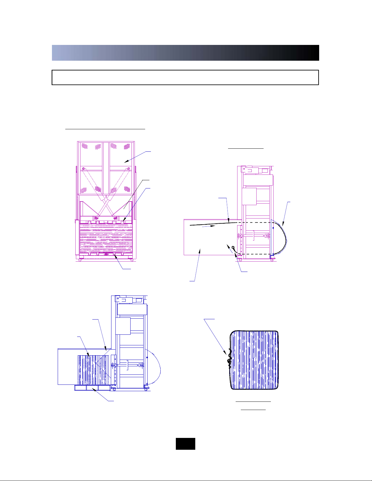
DIAGRAM - BALE TIE OFF/BALE EJECT
FRONT VIEW OF BALER
BALE TIE - TIGHTENED
HAND TIGHT
BALE DURING
EJECTION
PALLET OR BALE CART
RECOMMENDED FOR
SUPPORTING BALE
SIDE VIEW
BALE CHAMBER
DOOR OPENED
SIDE VIEW
- BALE
1-8
BALE TIES ENTER
THROUGH PLATEN
LOOPED END FIRST
BALE TIES EXIT
THROUGH FLOOR
EJECTED
BALE
BALE TIE SLOTS
PLATEN
BALE TIE SLOTS
FEED GATE OPENS
WHEN BALE DOOR
IS OPENED
BALE TIES
FOLLOW
WIRE
GUIDES
1 OPERATION
Page 11

TIE SLOT CLEANING
1-9
FRONT VIEW
BALE
FEED GATE
TIE SLOTS
SLOT CLEANING TOOL
HANDLE
AT TIMES THE TIE SLOTS MAY BECOME OBSTRUCTED WITH MATERIAL AND PREVENT THE
WIRE TIES FROM PROPER INSERTION THROUGH THE SLOTS AND AROUND THE BALE. THE
BALER IS SUPPLIED WITH A SLOT CLEANING TOOL FOR RODDING OUT THE TIE SLOTS.
TO USE, INSERT THE TOOL INTO THE BLOCKED SLOT AND PUNCH OR DRAG THE MATERIAL
OUT.
IF THE WIRE GUIDES BECOME OBSTRUCTED WITH MATERIAL , THE BALER SHOULD BE
EMPTIED, LOCKED OUT AND TAGGED OUT, AND THE PLATEN SHOULD BE CHOCKED AS
SHOWN IN THE MAINTENANCE SECTION OF THIS MANUAL (2-2) BEFORE CLEANING THE WIRE
GUIDES.
1 OPERATION
Page 12

WARNING DECAL REQUIREMENTS
When your baler leaves the factory, several WARNING DECALS are installed for
protection. These labels are subject to wear and abuse due to the nature of the
operation. THESE DECALS MUST BE MAINTA I N E D . Additional decals may be
purchased through your distributor.
DECALS
1-10
1 06-2682 1 MARATHON LOGO/A DOVER COMPANY
2 06-3309 6 CE RATED DANGER STRIPE (275mm)
3 06-2582 1 NO ACCESS FOR UNAUTHORIZED PERSONS
4 06-2755 1 DO NOT ENTER/CONFINED SPACE
5 06-0419 1 READ MANUAL
6 06-0130 2 OPERATING INSTRUCTIONS
7 06-2702 1 PINCH POINT/MOVING PARTS
8 06-2681 3 HOT SURFACE/BURN HAZARD
9 06-0468 1 CE MODEL/SERIAL NUMBER
10 06-2757 1 ELECTRICAL LOCKOUT
11 06-2758 1 ELECTRICAL SHOCK HAZARD
DESCRIPTION
See next page for Decal Placement.
1 OPERATION
Page 13

DECAL PLACEMENT
1-11
1 OPERATION
Page 14

2 MAINTENANCE
LOCK-OUT & TAG-OUT INSTRUCTIONS
06-0045
460
VOLTS
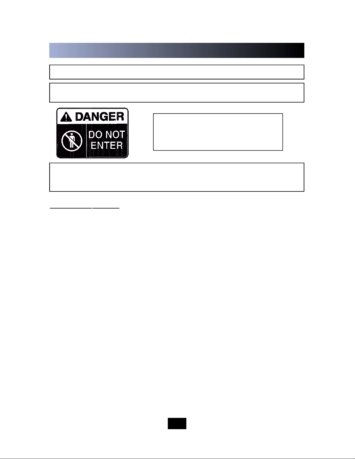
DANGER
ELECTRICAL: The panel box contains high voltage
components. Only authorized service personnel
should be allowed inside the box. Authorized service
personnel should be allowed inside the box only
after the baler has been locked-out and tagged-out.
FOREWORD: Before entering any part of the baler, be
sure that all sources of energy have been shut off, all
potential hazards have been eliminated, and the baler
is locked-out and tagged-out in a ccordance w ith
O S H A and ANSI requirements. Before servicing the
hydraulic system or the inside of the bale chamber,
THE PLATEN MUST BE PROPERLY SUPPORTED A S
SHOWN ON THE NEXT PA G E.
The specific lock-out and
tag-out instructions may vary from company to company (i.e.
multiple locks may be required, or other machinery may need to
be locked-out and tagged-out). The following instructions are
provided as minimum guidelines.
HYDRAULIC: Stored hydraulic energy must be removed from the baler hydraulic
circuit for complete lock-out and tag-out. Make sure that this energy has been relieved
by manually depressing the solenoid valve pin located in the center of the coil end of
each valve. See Diagrams on pages 2-4 and 2-11.
2-1
INSTRUCTIONS
1. Move the main disconnect lever to the OFF position.
2. Padlock the disconnect lever with a keyed padlock and take the
key with you.
3. Along with the padlock, place an appropriate, highly visible,
warning tag on the disconnect lever.
The tag should provide a warning such
as: “ Danger: Do not operate equipment. Person working on equipment. Warning: Do
not energize without the permission of _________________________.”
4. After locking and tagging the baler, try to start and operate the
baler (as outlined in the Operating Instructions) to make sure the
lock-out and tag-out is effective. If the lock-out and tag-out is
effective, remove the key from the keyswitch and take with you.
(Typical disconnect shown, other
types may lock-out differently.)
OFF
400
Page 15

SUPPORTING OF PLATEN
BALE CHAMBER
DOOR, OPEN
FEED GATE OPEN PLATEN IN UP
POSITION
100mm x100mm
WOOD BEAM IN
EACH REAR
CORNER
FRONT VIEW OF BALER
WARNING: BEFORE ENTERING BALE CHAMBER FOR SERVICE, BE SURE THAT
THE PLATEN IS SECURELY SUPPORTED. AT A MINIMUM, USE TWO WOODEN
100mm x 100mm BEAMS (GOOD CONDITION), CUT TO FIT SNUG IN EACH REAR
CORNER OF THE CHAMBER WHILE SUPPORTING THE PLATEN IN THE UP
POSITION. THE TOP END OF EACH BEAM SHOULD BE IN THE EXTREME
CORNER, WHILE THE BOTTOM END SHOULD BE POSITIONED OVER THE
OUTER TIE SLOT IN THE FLOOR. SEE DIAGRAM BELOW.
BEAM OVER
OUTER TIE
SLOT IN FLOOR
2-2
DANGER: DO NOT CLIMB ON SIDES OF BALER. USE A LADDER OR WORK
P L ATFORM WHEN WORKING ON TO P OF THE BALER OR OTHER AREAS OF
THE BALER THAT CANNOT BE REACHED FROM GROUND LEVEL.
WARNING: FEED GATE WILL EXTEND ABOVE THE TOP OF THE BALER
WHEN THE FEED GATE IS RAISED.
CAUTION: TURN DISCONNECT TO THE OFF POSITION, LOCK-OUT AND TAG-
OUT POWER BEFORE SUPPORTING THE PLATEN.
2 MAINTENANCE
Page 16

Check external hoses for chafing, rubbing, leakage, or other deterioration and
damage. Tighten all fittings as necessary. Check hydraulic cylinder, cylinder pin and
bolts for signs of wear and fatigue.
Check for any obvious unsafe conditions, such as operator obstructions, in baler
area.
Check oil level in hydraulic reservoir.
Lubricate the door hinge, and mechanical door lock with oil.
Check magnetic interlock on feed gate for proper operation.
Apply a light coating of all purpose grease in the feed gate tracks.
Apply a light application of all purpose oil to the feed gate latch moving parts.
Remove any pieces of materials on top of the platen.
Check functional operation of controls and options (stop button, timers, lights, etc.).
Check hydraulic cylinders, and hoses, for leakage, chafing and wear.
PERIODIC MAINTENANCE
1.
2.
3.
4.
5.
6.
7.
8.
1.
2.
MONTHLY
THREE MONTHS
ANNUAL FILTER MAINTENANCE
ANNUALLY
1.
2.
3.
Replace the hydraulic fluid. See Recommended Oil (page 2-14).
Electric motor bearings should be lubricated once a year.
Clean the top of the power unit to remove the dirt build up.
2-3
WARNING: BEFORE PERFORMING ANY MAINTENANCE OR SERVICE PROCEDURES ON THE
BALER, MAKE SURE THE BALER IS LOCKED-OUT AND TAGGED-OUT PER THE INSTRUCTIONS
ON PAGE 2-1. FOR MAINTENANCE INSIDE THE BALE CHAMBER, SEE THE PLATEN CHOCKING
PROCEDURE ON PAGE 2-2.
The hydraulic filter should be cleaned at regular annual intervals.
The filter may be removed from the power unit through the cleanout cover in the top
of the reservoir.
Care should be exercised in cleaning the filter to insure that the element is not torn.
Clean the element with a soft brush and standard industrial solvent.
Replace the filter after cleaning and check fittings for tightness. Pump noise and a
"crackle" sound is most often caused by air ent ering the pump suction line.
Tightening the suction fittings will usually eliminate the problem.
1.
2.
3.
4.
2 MAINTENANCE
Page 17

1.
2.
3.
4.
5.
6.
7.
8.
9.
10.
11.
12.
13.
PRESSURE SETTING
HYDRAULIC SYSTEM PRESSURE SETTING
DANGER: DO NOT CLIMB ON SIDES OF BALER. USE A LADDER OR WORK PLATFORM
WHEN WORKING ON TOP OF THE BALER OR OTHER AREAS OF THE BALER THAT CAN
NOT BE REACHED FROM GROUND LEVEL.
Using the “MANUAL DOWN” button, run
the platen to the fully down position.
Lock-out and Tag-out the power per the
instructions on page 2-1.
Relieve any stored hydraulic pressure by
pressing in on the solenoid valve pins
located on each end of the directional
contro l valve. Use a small blade
screwdriver or s mall allen wrench to
perform this operation.
Remove the 1/4” plugs in the “A” and “B”
port fittings where the hydraulic hoses
enter the back of the baler, and install a
pressure gauge in each port (2 gauges
required).
RELIEF VALVE
“A” PORT
“B” PORT
COUNTERBALANCE VALVE
Loosen the lock nut on the counterbalance valve and adjust the valve counter
clockwise all the way out.
Remove the Lock-out and Tag-out.
Insert the key into the key switch and turn the key to the “ON” position.
Press the “MANUAL UP” button and raise the platen to the fully up position.
While continuing to hold the “MANUAL UP” button, loosen the lock nut on the Relief
Valve and adjust the relief pressure to 150 psi. Use the pressure gauge in the “B”
port to read this pressure. Release the “MANUAL UP” button.
Press the “MANUAL DOWN” button and adjust the counterbalance valve clockwise
until the platen moves in the downward direction freely. Tighten the lock nut on the
counterbalance valve.
Continue to hold the “MANUAL DOWN” button and adjust the Relief Valve to 650
psi. Use the pressure gauge in “A” port to read this pressure. Release the
“MANUAL DOWN” button.
Remove the cap from the Unloading Valve adjustment screw located on the pump.
Press the “MANUAL DOWN” button again and adjust the unloading valve screw to
unload the high flow section of the pump. Turning the screw clockwise increases the
unloading pressure, while turning the screw counter clockwise decreases the
unloading pressure. With the relief pressure at 500 psi., the pump will have a
destinctive sound when the pump unloads. Replace the cap on the Unloading Valve
adjustment screw.
SUBPLATE
02-3965
2-4
WARNING: FEED GATE WILL EXTEND ABOVE THE TO P OF THE BALER WHEN THE
FEED GATE IS RAISED.
(CONTINUED ON NEXT PAGE)
2 MAINTENANCE
Page 18

PRESSURE SETTING AND INTERLOCK TESTING
DANGER: DO NOT CLIMB ON SIDES OF BALER. USE A LADDER OR WORK PLATFORM
WHEN WORKING ON TOP OF THE BALER OR OTHER AREAS OF THE BALER THAT CAN
NOT BE REACHED FROM GROUND LEVEL.
WA R N I N G : FEED GATE WILL EXTEND ABOVE THE TO P OF THE BALER WHEN T H E
FEED GATE IS RAISED.
HYDRAULIC SYSTEM PRESSURE SETTING-(continued)
Continue to press the “MANUAL DOWN” button and adjust the Relief Valve to
1800 psi.
While holding 1800 psi. adjust the pressure switch until Relay 3 (R3) energizes.
Continuing to press the MANUAL DOWN button, adjust the relief valve to 2000 psi.
Tighten the lock nut on the Relief Valve.
Lock-out and Tag-out power per the instructions on page 2-1.
Relieve any stored hydraulic pressure by pressing in on the solenoid valve pins as
described in Step 3.
Remove the pressure gauges from the “A” and “B” ports and reinstall the 1/4” plugs.
Remove the Lock-out and Tag-out and turn the power “ON”. The pressure settings
are now complete.
14.
15.
16.
17.
18.
19.
20.
21.
This baler is equipped with a solid state output magnetic interlock switch. Because
it is a semiconductor device, it can not be checked with a continuity light or OHM
tester. The switch must be checked with the power ON. The RED WARNING
LIGHT on the control panel has been provided to indicate if the switch is working
properly.
To check the switch, turn the keyswitch to the ON position. When the feed gate or
bale door is open, the light should be off. When the bale door and feed gate are
closed, the light should be on.
If further verification is required, a voltmeter (120V) may be connected to terminal
#2A and terminal #7 in the panel box. The meter should read “0” volts with the gate
open and 120 volts with the gate closed.
In no instance should the baler operate in either MANUAL DOWN or AUTOCYCLE
with the feed gate up or bale door open.
1.
2.
3.
4.
MAGNETIC INTERLOCK TESTING
2-5
WARNING: IF THE INTERLOCK IS NOT WORKING PROPERLY, DISCONNECT
THE POWER AND LOCK-OUT AND TAG-OUT THE BALER UNTIL REPAIRS CAN
BE MADE.
2 MAINTENANCE
Page 19

CYLINDER REMOVAL AND REBUILDING
CYLINDER REMOVAL
Close the feed gate.
Turn on power and lower the platen using the MANUAL DOWN button. Turn off power.
Disconnect and Lock-out and Tag-out power per instructions on page 2-1.
Open the bale door. When the bale door is opened, the feed gate will raise.
Support platen with fork lift to take pressure off of the cylinder pins and to prevent the platen from
falling when pins are removed.
Remove bolts and cotter pins from the cylinder pins.
Remove platen from front of baler.
Turn on power and retract cylinder rods.
Disconnect and Lock-out and Tag-out power per instructions on page 2-1.
Relieve hydraulic pressure by manually depressing solenoid valve (both sides).
Relieve pressure on the counter balance valve. Loosen the locknut on the counterbalance valve
and adjust the valve clockwise all the way in to relieve the pressure.
Disconnect one hydraulic hose at a time. Plug the hose port before disconnecting another hose.
NOTE: Remove hose fittings slowly.
WARNING: BE SURE HYDRAULIC CYLINDERS ARE SECURELY SUPPORTED BEFORE
PROCEEDING.
With the hydraulic cylinders supported, remove the cylinder pins.
Remove cylinders.
Before reinstalling cylinders, check cylinder pins, bolts, and cylinder rods for signs of fatigue. Do not
reuse parts if wear or cracks are present.
To reinstall the cylinders, reverse the above steps.
NOTE:Use new bolts, nuts, and cotter pins when re-installing the cylinder pins.
After reinstallation of cylinder(s), readjust pressure on the counter balance valve. See Page 2-4 for
proper procedures.
1.
2.
3.
4.
5.
6.
7.
8.
9.
10.
11.
12.
13.
14.
15.
16.
17.
DANGER: DO NOT CLIMB ON SIDES OF BALER. USE A LADDER OR WORK PLATFORM WHEN
WORKING ON TOP OF THE B ALER OR OTHER AREAS OF THE BALER THAT CAN NOT BE
REACHED FROM GROUND LEVEL.
WARNING: FEED GATE WILL EXTEND ABOVE THE TOP OF THE BALER WHEN THE FEED GATE
IS RAISED.
2-6
CYLINDER REBUILDING
1.
2.
3.
4.
5.
6.
7.
8.
9.
10.
11.
Remove hydraulic cylinder from baler.
Remove retainer nut from gland.
Remove internal retaining ring.
Remove rod from cylinder barrel.
Remove piston locknut and piston from cylinder rod.
Replace all seals. Discard old seals and old piston locknut.
Replace gland on rod.
Install piston on cylinder rod using new locknut (included in seal kit).
NOTE: Do not reuse old locknut. Torque new locknut to 275 - 330 ft-lbs.
Install piston and rod assembly in cylinder barrel. Be careful not to damage seals.
Install gland in barrel. Install internal retaining ring.
Install retainer nut to gland. Reinstall cylinder in baler.
2 MAINTENANCE
Page 20

FEED GATE LATCH A D J U S T M E N T
FEED GATE
LATCH
SPRING
FEED GATE
STRIKER
TENSION
ADJUSTMENT
NUT
NOTE: Adjustment is made by tightening or
loosening the TENSION ADJUSTMENT NUT with
the feed gate in the up position. Spring tension
should not exceed 5 lbs to prevent excessive
wear on the feed gate latch and striker.
NOTE: In the event of excessive wear, the feed gate latch
STRIKER is removable and replaceable. Striker may be
replaced by removing the two (2) striker bolts. Access to the
striker bolts can be achieved by removing the front cover
from the bale door
2-7
BALE DOOR
BOLTS
FOR
STRIKER
2 MAINTENANCE
Page 21

PRINCIPLES OF OPERATION
2-8
OPERATING CHARACTERISTICS:
With the key switch in the ON position, and the bale door and feed gate closed, pressing the
AUTOCYCLE push button will cause the machine to operate one complete cycle. Pressing the
AUTOCYCLE switch closes three sets of contacts: (1) energizes Relay 1, (2) energizes Relay
2, (3) energizes the motor starter coil. With the motor running, oil is supplied to the subplate and
directional control valve. With Relay 1 energized, oil is directed to the base end of the cylinders
and causes the platen to move in the downward direction. The platen will move in the
downward direction until enough pressure is detected by the pressure switch to de-energize
Relay 1 and shift the directional control valve to direct the oil to the rod end of the cylinders and
start the platen moving in the upward direction. When the platen raises high enough to catch
and open the feed gate, the control voltage in the magnetic interlock switch is broken and
deenergizes the motor starter and the power unit shuts down. When the motor starter is
deenergized, an auxiliary contact de-energizes Relay 2.
When Relay 2 energizes, a contact is closed to start Timer 1. Timer 1 is used to shut the power
unit down if the pressure switch never opens by either: (1) not enough pressure, or (2) by
malfunction. Timer 1 sets at 50 seconds. If Timer 1 times out, Relay 2 is de-energized which
deenergizes the motor starter coil. When the motor starter is de-energized, it also de-energizes
Relay 1, and the power unit shuts down.
When enough material has been compacted in the bale chamber to stop the platen while
holding the limit switch in the open position, and the pressure switch actuates, Relay 2 will
deenergize. When Relay 2 de-energizes, the motor starter coil will de-energize, the power unit
will shut down, and the BALE MADE LIGHT will come on.
NOTE: When the BALE MADE LIGHT comes on, it is time to tie the bale. See Bale Tie Off
instructions on page 1-7.
2 MAINTENANCE
Page 22

FULL LOAD
AMPERAGE
DISCONNECT
SIZE (MAX)
TIME DELAY
FUSE (MAX)
INVERSE TIME
CIRCUIT BREAKER (MAX)
30 m
60 m
90 m
CHARTS
2-9
2 MAINTENANCE
ELECTRICAL REQUIREMENTS
16.7 15.2 8.5
30 AMP 30 AMP 30 AMP
30 AMP 25 AMP 15 AMP
40 AMP 40 AMP 20 AMP
10 10
12 AWG/ 4mm
2
6 8
12AWG/ 4mm
2
4 6
10AWG/ 6mm
2
VOLTAGE
208 VAC 230 VAC
WIRE SIZE (75 C)
400 VAC/50 HZ
20 m 12
12
12 AWG/ 4mm
2
5 HP 400V 3 PHASE 50HZ
Page 23

PANEL BOX
2-10
TERMINAL
BLOCK
MOTOR
STARTER
W/OVERLOADS
2 AMP
FUSE
RELAYS AND BASES
TERMINAL STRIP
GROUND
GROUND
TIMER
OVERLOAD
ADJUSTMENT
2 MAINTENANCE
Page 24

POWER UNIT
2-11
BREATHER CAP
DIRECTIONAL CONTROL
VALVE
SUBPLATE
RELIEF VALVE (RV1)
SIGHT GAUGE
COUNTERBALANCE VALVE
SUCTION FILTER
(LOCATED IN
RESERVOIR)
CLEAN OUT COVER
PUMP
PUMP/MOTOR
ADAPTER
HUB COUPLING
MOTOR
NOTE: See RECOMMENDED OIL
on page 2-14.
2 MAINTENANCE
Page 25

ELECTRICAL SCHEMATIC
2-12
E-6415
2 MAINTENANCE
Page 26

HYDRAULIC SCHEMATIC
2-13
2 MAINTENANCE
E-0489
5 HP / 3.7 KW
6 GPM / 22.7LPM
Page 27

PARTS LIST
2-14
WARRANTY AND SERVICE ON MOTORS
If the baler motor fails under warranty, have it checked by a qualified electrician or service person. If
there is no problem with fuses or wiring, the motor should be taken to the nearest authorized motor
warranty shop. If you do not have a list of qualified shops, contact Marathon Equipment Co. The motor
warranty shop will be able to inspect the motor and determine if it is factory defective. If the motor failed
due to defects in material or workmanship, contact the factory to determine if the motor will be replaced
or repaired. If motor failure was not due to defective material or workmanship, it will be repaired only if
customer agrees to pay for expenses. Marathon Equipment Co. will not absorb cost for pickup and
delivery to service centers. Removal and reinstallation are covered in the standard warranty policy.
6. Shell -Turbo 46, Tellus 46
7. Quaker State - Dextron ll (ATF)
8. Citgo - Pacemaker 46, Tellus - AW46
9. Amoco - (Rycon)
1. Union - Unax-46, Unax-AW46
2. Gulf - Harmony 47, Harmony 48-AW
3. Exxon - Teresstic 46, Nuto 46
4. Texaco - Rando 46
5. Chevron - AW 46
RECOMMENDED OILS
PART # DESCRIPTION
02-0050 SUCTION FILTER
02-0197 BREATHER
02-0198 SIGHT GAUGE
02-0219 CLEAN OUT COVER
02-0628 DIRECTIONAL CONTROL VALVE
02-3902 COUNTER BALANCE VALVE
02-4037 PUMP/MOTOR ADAPTER
02-4207 SUBPLATE
02-0242 HUB COUPLING
99-7778 PUMP
02-4018 RELIEF VALVE
03-0010 LIMIT SWITCH ARM
03-0012 LIMIT SWITCH
03-4152 RELAY SAFETY MONITORING
03-4730 PLC EXPANSION 4 IN 2 OUT
03-4729 PLC 6 IN 4 OUT
03-5013 MOTOR STARTER OVERLOAD
03-0335 RED OMNIGLOW LIGHT
03-0351 TIMER RETAINING CLIP
PART # DESCRIPTION
03-4585 MAGNETIC SWITCH
03-0013 PRESSURE SWITCH
03-4832 MOTOR STARTER
03-0928 PUSHBUTTON SWITCH (BLACK)
03-0939 EMERGENCY STOP SWITCH
03-0934 KEY SWITCH
03-0936 CONTACT BLOCK N/O
03-0937 CONTACT BLOCK N/C
03-0987 PUSHBUTTON SWITCH (GREEN)
03-5165 MOTOR, 5 HP, 3 PHASE
04-3134 CYLINDER, 3B 1.5R 25S
05-0277 SPRING
05-0283 CHAIN, 2040 RIVIT
05-0285 SPROCKET F/GATE
05-0664 CHAIN MASTER LINK
05-2384 TURNBUCKLE W/200mm WHEEL
06-1409 CASTER
2 MAINTENANCE
Page 28

These instructions are not intended as a substitute for training and
experience in proper use, safety procedures, maintenance, or installation
of this equipment.
Marathon does not assume responsib ility for the insta llation
procedures of this equipment. Conformance to applicable local,
state, and federal laws concerning installation rests with the
customer.
3 INSTALLATION
GENERAL INSTALLATION
CAUTION:
DECALS
Installation of the baler is not complete until an inspection of the warning
decals has been made. Decals should be clearly visible, legible, securely
applied, and in the proper location. For decal description and location, see
DECALS and DECAL PLACEMENT in Section 1, pages 10 & 11.
3-1
DANGER: DO NOT CLIMB ON SIDES OF BALER. USE A LADDER OR
WORK PLATFORM WHEN WORKING ON TO P OF THE BALER OR
OTHER AREAS OF THE BALER THAT CAN NOT BE REACHED FROM
GROUND LEVEL.
WA R N I N G : PA RTS OF THE FEED GATE WILL EXTEND ABOVE T H E
TOP OF THE BALER WHEN THE FEED GATE IS FULLY RAISED.
This baler is designed for INDOOR USE ONLY.
Review this manual before beginning the installation. Study the
jobsite and installation requirements carefully to be certain all
necessary safeguards and/or safety devices are provided to protect
all personnel and equipment during the installation and as a
completed system.
Page 29

ANCHORING TO CONCRETE PAD
3-2
The concrete pad should be level, and a minimum of 3000 PSI concrete,
steel reinforced, 150mm thick. Anchor baler to floor using anchor brackets
on sides of baler base. Two 18mm diameter anchor bolts required, Red
Head type recommended.
1. Roll baler to the desired location.
2. Unbolt the Anchor Bracket from the baler.
(both sides)
3. Turn the Anchor Brackets over and re-bolt
them to the baler.
4. Anchor the Anchor Bracket to the floor.
(both sides)
ANCHOR BRACKET IN
SHIPPING POSITION
TURN ANCHOR BRACKET
OVE AND ANCHOR TO
FLOOR
3 INSTALLATION
Page 30

06-0045
460
VOLTS
DANGER
The panel box contains high voltage
components. Only authorized service
personnel should be allowed inside.
See Lock-Out & Tag-Out instructions in
the Maintenance section.
ELECTRICAL INSTALLATION
WARNING: BEFORE MAKING ANY ELECTRICAL CONNECTION, BE SURE
THAT THE
MAIN DISCONNECT SWITCH HAS BEEN LOCKED-OUT AND TAGGED-
OUT PER THE LOCK-OUT AND TAG-OUT INSTRUCTIONS ON PAGE 2-1.
1. BRANCH CIRCUIT PROTECTION IS NOT PROVIDED WITH THIS UNIT,
AND
MUST BE PROVIDED BY THE INSTALLER. This disconnect switch
must be fused, lockable, and within sight of, and not to exceed 17m
from the baler, per the National Electrical Code. Additional local codes
may apply. Use the FUSE AND CIRCUIT BREAKER chart and the WIRE
SIZE chart in the MAINTENANCE section of this manual for reference
during the electrical installation.
2. Before connecting power to the baler, check the incoming line voltage
with a voltmeter. Also, check voltage wiring in the baler panel box. If the
baler is not wired to the proper voltage, make necessary corrections
before proceeding.
3. A lockable disconnect switch IS NOT PROVIDED in the panel box.
Incoming power should be connected to the top of the terminal block. Be
careful not to let incoming wires touch each other. A properly sized
equipment ground wire should be connected to the enclosure ground lug.
3-3
DANGER
: All equipment should be grounded per National Electric Code.
GROUNDING INSTRUCTIONS
This appliance must be connected to a grounded, metal, permanent wiring system; or
an equipment grounding conductor must be run with the circuit conductors and
connected to the equipment grounding terminal or lead on the appliance.
If there is any doubt whether the equipment is properly grounded, a qualified electrican
should be consulted.
3 INSTALLATION
400
Page 31

WARNING: BEFORE START-UP, REPLACE THE 3/4” PLUG ON THE TOP OF THE
POWER UNIT R E S E R VOIR WITH THE FILLER BREATHER CAP. THIS CAP I S
SHIPPED INSIDE OF THE PANEL BOX.
D A N G E R : DO NOT CLIMB ON SIDES OF BALER. USE A LADDER OR WORK
PLATFORM WHEN WORKING ON TOP OF THE BALER OR OTHER AREAS OF THE
BALER THAT CAN NOT BE REACHED FROM GROUND LEVEL.
C A U T I O N : MAKE SURE PERSONS AND MAT E R I A L ARE CLEAR OF CHARGE
BOX AREA.
1. After the electrical connections are complete, check motor rotation by the
following:
MOTOR ROTATION APPLIES TO THREE PHASE UNITS ONLY.
a. Close bale chamber door and feed gate.
b. Turn disconnect switch to the ON position.
c. Have someone turn ON the keyswitch and depress the AUTO-
CYCLE button for one second and then immediately depress the
EMERGENCY STOP button. Check motor rotation by watching the
hub coupling through the slot in the pump-to-motor adapter. There
is a rotation decal on the power unit showing correct rotation. In the
event that this decal is missing, look at the hub coupling from the
motor end. Rotation should be clockwise.
CAUTION: If the pump rotates backward,
STOP IMMEDIATELY!
The pump will be damaged if it is operated in reverse even for
short periods. Reversing any two incoming power lines will change
the motor/pump rotation.
2. With the platen fully raised, check to be sure the oil reservoir is filled to the 3/4
level on the sight gauge (Refer to page 2-14 for hydraulic oil recommendations).
The hydraulic system pressure has been factory set.
3. The baler is equipped with an electrical interlock which prevents the use of
the AUTOCYCLE and MANUAL DOWN functions when the feed gate is in the up
position. If either of these buttons start the baler when the feed gate is up,
discontinue use of the baler until repairs have been made.
4.
MAKE SURE THAT THE OPERATORS ARE TRAINED IN THE
PROPER USE OF THIS EQUIPMENT.
START-UP INSTRUCTIONS
3-4
WARNING: PARTS OF THE FEED GATE WILL EXTEND ABOVE THE TOP OF THE
BALER WHEN THE FEED GATE IS FULLY RAISED.
3 INSTALLATION
 Loading...