

Page 1

UNIPRO v3.5
Users Manual
COPYRIGHT © 1998
MARATHON MONITORS INC
Page 2

Marathon Monitors Inc.
Description and Applications
The Marathon Monitors Inc. UNIPRO Controller/Programmer
represents the latest technology in microprocessor-based process
control instrumentation. Through flexible PID (Proportional,
Integral, Digital) control along with programmable features, even
the most complex, system can be handled. For a thorough
explanation of PID please refer to Zeigler and Nichols; “Optimum
Settings for Automatic Controllers”, Transactions of ASME, Nov.
1942. Or St. Clair, David W.; Controller Tuning and Control Loop
Performance, a Primer; Straight-Line Control Company, Newark
,Delaware 1989.
The UNIPRO's control actions are based upon input from a
Thermocouple, RTD, Voltage or Current source. The
UNIPRO allows Manual, Automatic, or Programmed control
of a single loop. Its built-in RS-422 computer interface
allows it to be completely supervised by a computer, either
on-site or in some remote location within the plant. The
Programmer can be used, and is strongly recommended, to
allow complete control of temperature or other process
cycles.
The following features have been included to allow use of the
instrument in a wide variety of applications:
Fully site-configurable for single point control from one of three
(3) fully isolated analog input sources, each separately configurable
for thermocouple, RTD, voltage, or current.
Powerful process/logic programmer that can store up to
two-hundred (200) programs, each consisting of nineteen (19)
steps, subroutine calls, test and branch capability, and full access to
all instrument parameters.
Unipro 3.5 Process Control 1 Aug. 1997
Page 3

Marathon Monitors Inc.
Two (2) control output triacs for use in single or dual control
mode.
Two (2) fully isolated analog outputs, each separately configurable
for voltage or current output.
Two (2) configurable alarm triacs, assignable as process Alarms,
deviation alarms, program alarms, or fault alarms.
Four (4) programmer events, assignable in any combination as
either inputs or outputs (expandable to 16 I/O with external event
boards).
Three (3) communication ports for talking with host computers,
controllers, and discrete digital and / or analog event expansion
racks.
This manual provides all of the information required to install,
operate and maintain the MMI UNIPRO.
The manual is divided into parts: Installation, Setup and
Configuration, Operation, Programming, and Maintenance and
Troubleshooting. Installation and Setup and Configuration will be
used initially to get the instrument into use. Operation and
Programming will be used daily. Maintenance and
Troubleshooting will be used for servicing the instrument
periodically or if trouble occurs.
Unipro 3.5 Process Control 1 Aug. 1997
Page 4

Marathon Monitors Inc.
Installation
Installation Location
The UNIPRO instrument is designed for 1/8 inch panel mounting in
a DIN standard opening of 5.43 inches square (adapter panels
available by special order). Required rear clearance is 10.5 inches
to allow for wiring. As with all solid state equipment, the
controller should be away from excessive heat, humidity, and
vibration (refer to specifications). Since the unit uses red LED
display devices, avoid placing it in direct sunlight to reduce
interference with the display's visibility. The instrument requires
100/120/200/240 VAC (jumper selectable on power interconnect
board inside the rear panel) 50/60 Hz. It should not be on the
same circuit with other noise-producing equipment such as
induction machines, large electrical motors, etc. All instrument
wiring must be run separate from all control wiring.
Panel Mounting/Removal
Because the instrument uses a ventilated enclosure, it is not
dust-tight and should therefore always be mounted in a sealed
control panel. To mount the UNIPRO in a control panel, a hole
must be cut 5.43 inches square in the necessary location on the
panel. The following procedure should be followed to mount the
UNIPRO in the panel.
1. Insert the unit into previously cut out 5.43 inches square
hole in the panel.
2. While supporting the unit, insert one slotted clamping
bracket, with head of the bolt facing to the rear of the unit, into the
0.62 inch by 0.82 inch cutout on the side of the unit.
Unipro 3.5 Process Control 1 Aug. 1997
Page 5

Marathon Monitors Inc.
Unipro 3.5 Process Control 1 Aug. 1997
Page 6

Marathon Monitors Inc.
3. Repeat step 2 for the opposite side of the unit.
4. With 1/8 inch HEX KEY wrench, alternately tighten bolts
on either side of the instrument to a torque of 4 in-lbs. (See warning
below). Insure rigidity of mounting.
Warning
To prevent warping of the unit's case, do not over tighten the
clamp bolts.
5. To remove the unit, loosen the side clamping brackets and
reverse steps 1 through 3 above.
Note
Unipro 3.5 Process Control 1 Aug. 1997
Page 7

Marathon Monitors Inc.
On subsequent removals and installations the rear
panel can be removed (4 screws) and the wiring
does not have to be disturbed.
Warning
All connections, rear panel installations and removals; plus
triac board installations and removals must be done with
power removed from TBA and TBB. All PC boards should
only be removed or installed with power off via the switch
mounted on the triac board. Otherwise, serious personal
and/or equipment damage can occur.
Thermocouples and Other Signal Wires
The wiring used to connect the signal wires to the instrument
should be run in a conduit, separate from any AC lines in the area.
This provides noise immunity and physical protection.
Thermocouples should be wired with the appropriate alloy
extension wire with no termination other than at the instrument. As
with all cold-junction compensating instruments, extreme care
should be used when an existing thermocouple is to be used for
both the Controller and another instrument at the same time.
Control Devices
The UNIPRO provides simple ON/OFF as well as Proportional
control through its two contact closure Control Outputs (TBA-7,
TBB-7, TBA-8, and TBB-8) and two Analog Outputs (TBD-13
through TBD-16). Refer to the Section on Control Modes for
more details on the outputs. This allows control through simple
ON/OFF devices or through Proportional control methods.
SIMPLE ON/OFF CONTROL: Set Control Mode for
ON/OFF Control. This provides contact closure at Control Output
#1 to control absolute heat application/removal for such devices as
heating elements, etc.
Unipro 3.5 Process Control 1 Aug. 1997
Page 8

Marathon Monitors Inc.
Three types of Proportional control are:
1. Time-Proportioning: Referring to the
modulation of the duty cycle. That is,
changing the ratio of On Time versus Off
Time in systems that use such devices as
heating elements, electronically
operated/assisted valves, or servo drives that
use analog command signals for control.
2. Position-Proportioning: Referring to the
adjustment of a variable positioning device
such as a positioning motor with slidewire
feedback.
3. Voltage or Current Output Proportioning:
An Analog output's (voltage or current)
amplitude is varied based on input from
rheostats, thermocouples, ammeters, etc. to
control heat applications.
The UNIPRO provides many ways to use the above control
methods. Setup has details for setting the Control Modes to
determine the method to be used. Some typical applications for the
Proportioning method are:
1. HIGH/LOW or HEAT COOL heat application system: Set
Control Modes for Time-Proportioning. This provides that
CONTROL OUTPUT #1 (TBA-7, TBB-7) and CONTROL
OUTPUT #2 (TBA-8, TBB-8) are in opposite conditions at either
extreme of the control range and are both OFF at the midpoint of
the control range.
2. ANALOG OUTPUT control: Set Control Modes for
Time-Proportioning. This provides a 0 to 5 VDC or 4 to 20 mA
output which is selectable on the ANALOG OUTPUT BOARD
(TBD-13 through TBD-16, see Section 2.14 and Section 8.0 for
Unipro 3.5 Process Control 1 Aug. 1997
Page 9

Marathon Monitors Inc.
more details). The output control is based on 0 to 99% of the
output device's control range. For example, 50% control would
equal 2.5 VDC out where 5 VDC equals maximum heat output of
the drive. This can be used with servo drives that require a voltage
or current command signal for controlling heat output or servo
positioning.
3. POSITIONING MOTOR with SLIDEWIRE FEEDBACK:
Set Control Modes for Single Position-Proportioning with slidewire
feedback. CONTROL OUTPUT #1 will drive the motor in the
open direction, CONTROL OUTPUT #2 in the close direction.
Remember, the above methods are just examples of the typical
applications of the UNIPRO. Please call your MMI representative
or application engineer for questions concerning your particular
system.
Chart Recorders
If a chart recorder is to be used, it must have input specifications
within the following ranges:
0 to 4 VDC
0 to 45 mA
corresponding to a FRONT PANEL display of 0-2000. The ideal
location of the recorder is adjacent to the instrument but it may be
located remotely if the connecting wires are properly shielded.
Long wiring runs from the chart recorder outputs may require
resistive termination
(2 K ohms or so) at the chart recorder input(s) should be isolated
from ground.
Computer Interface
If you wish to take advantage of the UNIPRO's RS-422 digital
communications capabilities, refer to "Communications" for more
details.
Unipro 3.5 Process Control 1 Aug. 1997
Page 10

Marathon Monitors Inc.
Alarms
Two user-programmable triac alarm contacts are available for
connection in appropriately-engineered systems.
Programmer
The Programmer can run an entire process, depending on how
thoroughly the capabilities are set up and used. Refer to
"Operation" and "Programming" for further information.
Unipro 3.5 Process Control 1 Aug. 1997
Page 11
Marathon Monitors Inc.
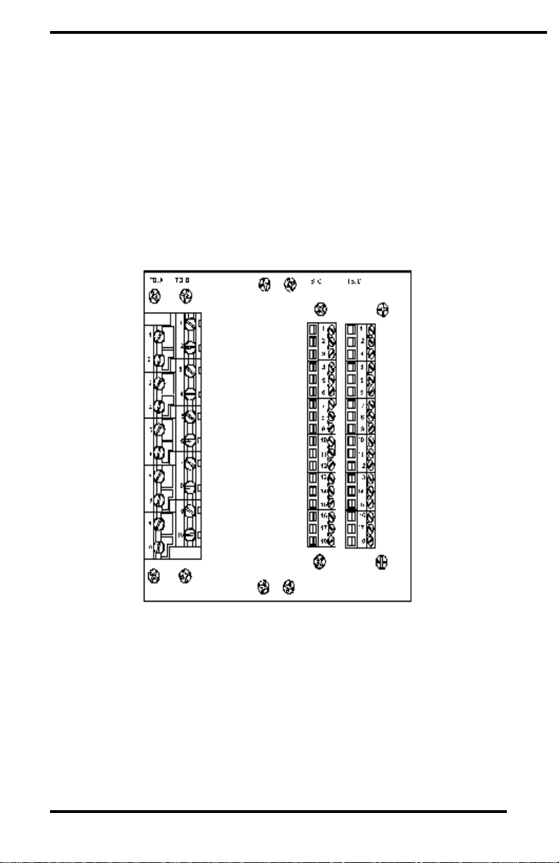
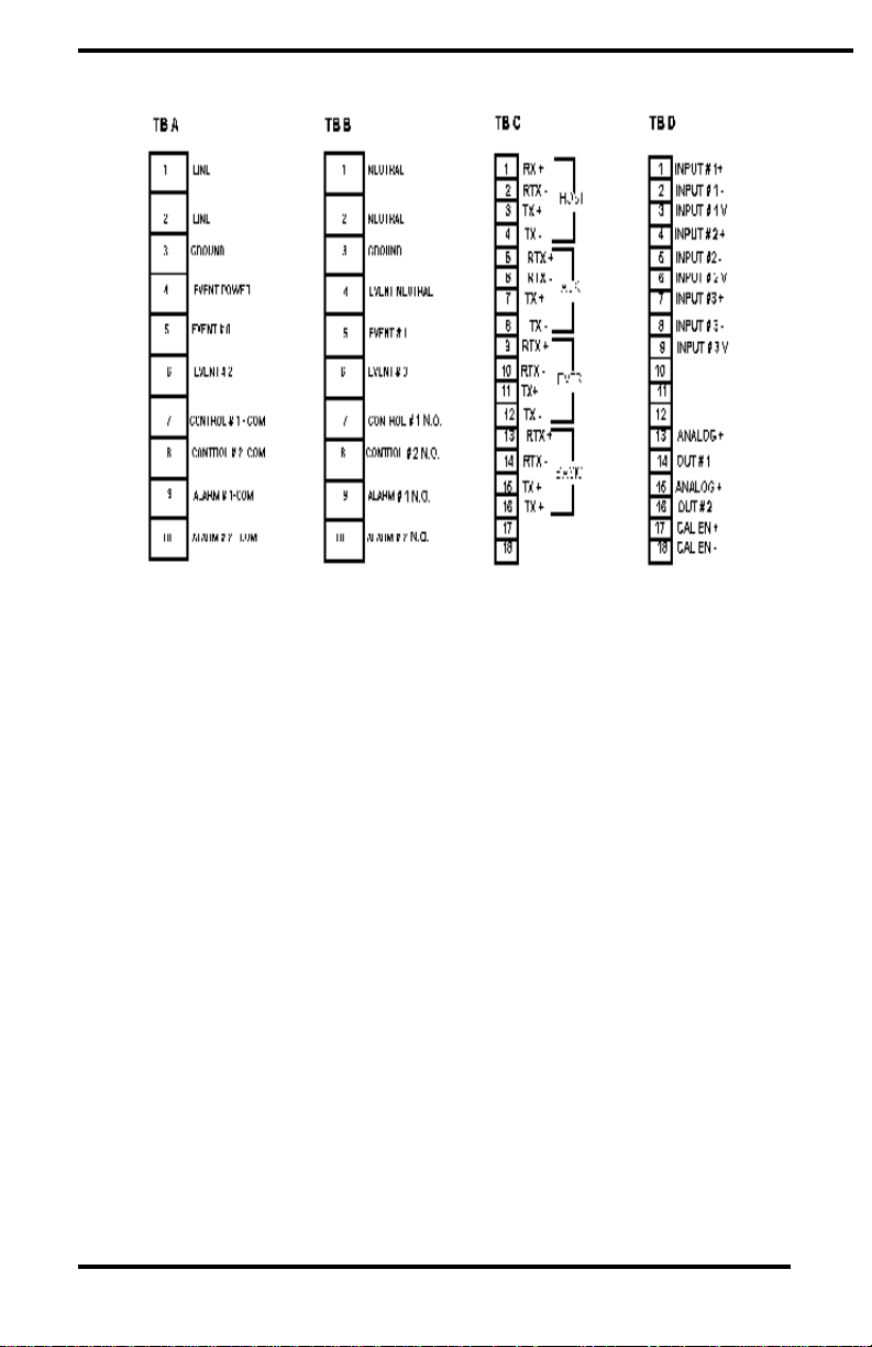
Electrical Connections
Connections to the unit are made via four terminal blocks, on the
rear panel, labeled TBA, TBB, TBC, and TBD. (Position 1 is at
the top the position 10 (TBA and TBB) or 18 (TBC and TBD) is at
the bottom of the terminal strip.) AC power, event, control, and
alarm connections are made on TBA and TBB. All
communications are on TBC and all analog I/O signals are on TBD.
Refer to the Figure below for a complete layout of the UNIPRO
rear panel connections.
Unipro 3.5 Process Control 1 Aug. 1997
Page 12

Marathon Monitors Inc.
Unipro 3.5 Process Control 1 Aug. 1997
Page 13
Marathon Monitors Inc.
UNIPRO Rear Panel
UNIPRO Electrical connections
AC Power
The UNIPRO requires 100/120/200/240 VAC at 1 AMP,
Communications
Three communications busses are at TBC and use RS-422 full or
half duplex protocol for all ports. (Refer to "Communications" in
Maintenance and Troubleshooting.) Typically, the HOST port will
connect to a host computer, the AUXILIARY BUSS to other
instruments, and the OPTOMUX PORT to OPTOMUX
I/O devices.
Unipro 3.5 Process Control 1 Aug. 1997
Page 14

Marathon Monitors Inc.
Analog Inputs
The UNIPRO allows for three analog inputs with their individual
functions determined by "daughter board" located on the analog
input board inside the unit. The standard connection, at TBD, will
have the first input as a thermocouple, the second for the oxygen
probe, and the third optionally used to input voltage or milliamp
signals.
Analog Outputs
Two, separate, isolated analog outputs are provided on TBD and
can be selected as 4-20 mV (for maximum accuracy, see
Specifications for further details) or 0-10 V output through DIP
switch settings on the analog output board. Additionally, outputs
can be calibrated by placing a jumper on the two terminals supplied.
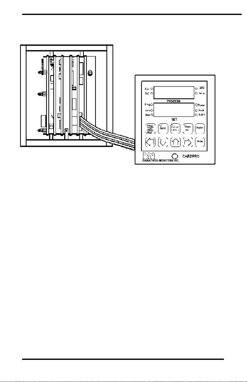
DIP Switch Setup
The user may use the UNIPRO in a multi-instrument system by
giving the instrument a unique HOST address, specified by using
the DIP switches on the Interface Board inside the UNIPRO
To get to the DIP switches, loosen the black knurled knob on the
front panel by turning in a counterclockwise direction. Carefully
remove the front panel but DO NOT remove the ribbon cable
connecting the front panel to the Interface Board. Safely support
the front panel near the instrument. Adjust the DIP switches per
Section 2.16 for the desired operating mode. When switch
adjustment is complete, replace the front panel to prevent
contamination.
Unipro 3.5 Process Control 1 Aug. 1997
Page 15
Marathon Monitors Inc.
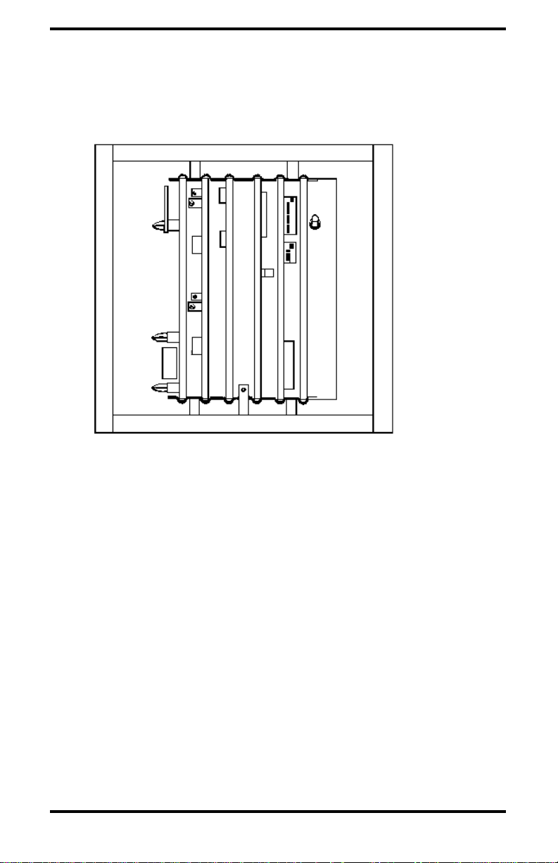
UNIPRO Front Panel Removal
Find the appropriate switches by referring to the figure below.
Unipro 3.5 Process Control 1 Aug. 1997
Page 16
Marathon Monitors Inc.
UNIPRO Internal Layout
DIP Switch Assignments
Bank 0
Switch # Description
1 Unassigned
2 Unassigned
3 Slide wire Deadband (see the following table)
4 Slide wire Deadband (see the following table)
5 Slide wire Deadband (see the following table)
6 Unassigned
7 Unassigned
8 Service (Must be OFF)
Selectable deadband for slidewire feedback control.
Unipro 3.5 Process Control 1 Aug. 1997
Page 17

Marathon Monitors Inc.
Slidewire Dead Band Offset
offset Switch 3 Switch 4 Switch 5
0.4% OFF OFF OFF
0.8% ON OFF OFF
1.2% OFF ON OFF
1.6% ON ON OFF
2.0% OFF OFF ON
2.4% ON OFF ON
2.8% OFF ON ON
3.2% ON ON ON
Unipro 3.5 Process Control 1 Aug. 1997
Page 18

Marathon Monitors Inc.
Each UNIPRO in a multiple instrument system must have a unique
address for proper communications.
HOST address selection switches: Bank 1Address
DEC HEX SW1 SW2 SW3 SW4
0 0 OFF OFF OFF OFF
1 1 ON OFF OFF OFF
2 2 OFF ON OFF OFF
3 3 ON ON OFF OFF
4 4 OFF OFF ON OFF
5 5 ON OFF ON OFF
6 6 OFF ON ON OFF
7 7 ON ON ON OFF
8 8 OFF OFF OFF ON
9 9 ON OFF OFF ON
10 A OFF ON OFF ON
11 B ON ON OFF ON
12 C OFF OFF ON ON
13 D ON OFF ON ON
14 E OFF ON ON ON
15 F ON ON ON ON
Unipro 3.5 Process Control 1 Aug. 1997
Page 19
Marathon Monitors Inc.
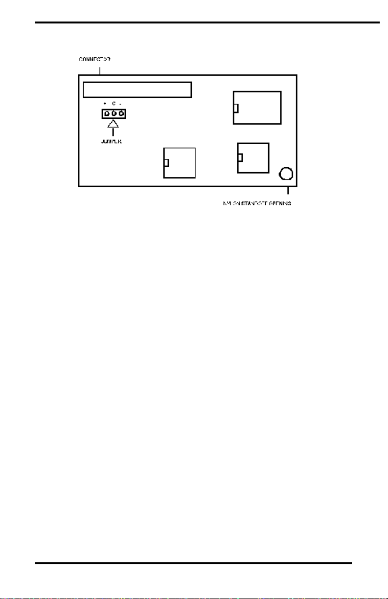
Thermocouple Burnout Jumper Selection
The thermocouple jumper selects either a full upscale or a full down
scale reaction to take place when a thermocouple fails or becomes
open. The jumper can be found on the thermocouple board, and
has two possible settings (see Figure). For full scale upwards, place
the jumper from the + to the C, and for full scale downwards, place
the jumper from the - to the C.
Unipro 3.5 Process Control 1 Aug. 1997
Page 20
Marathon Monitors Inc.
Setup And Configuration
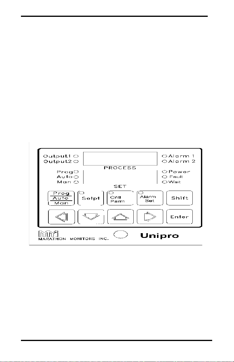
Front Panel
The front panel of the UNIPRO consists of three main parts, two
display windows and a keyboard. Refer to the figure shown below
for a layout of the front panel. The display windows each contain
four 14-segment digits that are used to display helpful messages
and numerical parameter values.
PROCESS Display
This 4 digit 14-segment display provides the value of the current
process value, along with messages for ease of operator use when
setting up parameters. The PROCESS window displays the step
number and OPCODE when in the Program Editor.
SET Display
Unipro 3.5 Process Control 1 Aug. 1997
Page 21

Marathon Monitors Inc.
This 4 digit 14-segment display provides the value of the process
setpoint value during Auto and Program operation. In Manual
mode the Time-Proportioning % Output value is displayed. During
operator input procedures this display shows the data being
entered. The SET window displays the corresponding data for the
OPCODES displayed in the PROCESS window when in the
Program Editor.
LEDs
Several small LEDs indicate operations and functions of the
UNIPRO. Ten are on the face and three are in the keys.
Output 1 indicates when the Output 1 Control relay is closed.
Output 2 indicates when the Output 2 Control relay is closed.
Alarm 1 indicates when the process value has closed the relay
based upon trip point and type of alarm.
Alarm 2 indicates when the process value has closed
the relay based upon the trip point and type of alarm. Also, if
Switch 6, Bank 1 is ON the LED indicates the closed control
output relay.
Prog indicates that a program is running and Automatic control is
activated. If flashing, the program is in HOLD. Refer to the
section "The Programmer".
Auto indicates that the UNIPRO is in Automatic control mode. If
flashing, a program is in HOLD.
Manual indicates that no control action is being executed by the
UNIPRO. If flashing, a program is in HOLD.
Power indicates that the UNIPRO's 5 volt power supply is
functioning.
Unipro 3.5 Process Control 1 Aug. 1997
Page 22

Marathon Monitors Inc.
Fault indicates that an open circuit is detected at the signal input.
Wait indicates that the Programmer is waiting for some condition
to be satisfied before continuing.
Setpt indicates that the Setpt Enter mode has been selected.
Cntrl Parm indicates that the Control Parameter Enter mode has
been selected.
Alarm Set indicates that the Alarm Setup mode has been selected
or one or both alarm values are non-zero.
Unipro 3.5 Process Control 1 Aug. 1997
Page 23
Marathon Monitors Inc.
Keyboard
The UNIPRO keyboard consists of ten keys for operating and
programming the instrument. There are no "hidden" keys on the
UNIPRO keyboard.
Various operations with the UNIPRO involve dual-key operations
using the [Shift] key in the same way a shift key on a typewriter is
used. When activating a dual-key assignment do not try to press
both keys simultaneously; rather, follow the sequence below:
1. Press and hold the[ Shift] key,
2. Press and release the second key,
3. Release the [Shift] key.
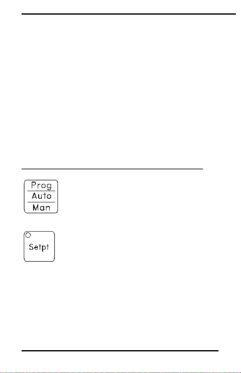
KEY DESCRIPTION
This key selects the operating mode of the
UNIPRO. The mode selected is indicated by
the illuminated LED.
This key selects the Setpoint Enter mode
where the Setpoint, Setpoint Offset and
Reference Number can be accessed and
altered. When used in the dual-key
operation Shift/Setpt it allows the operator
to pull any program into the edit space or
decrease the remaining time of a program step
if a program is currently running.
Unipro 3.5 Process Control 1 Aug. 1997
Page 24
Marathon Monitors Inc.
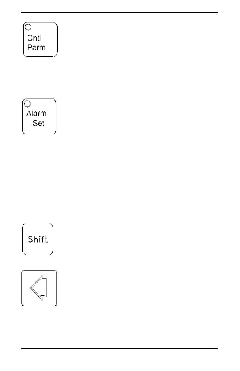
This key selects the Control Parameter Enter
mode where the Proportional Band, Reset,
Rate, Cycle Time and Percent Output values
(if in solenoid mode) can be accessed and
altered. When used in the dual-key
operation Shift/Cntrl Parm it selects the
keyboard Lock Level change mode.
This key selects the Alarm Setup mode where
the Alarm 1 and Alarm 2 conditions can be
accessed and altered or Alarm 2 can be used
to determine setpoint for auxiliary control
loop. When used in the dual-key operation
Shift/Alarm Set it selects the Thermocouple
Type, Custom Features, and Events Partition.
After Shift/Alarm Set the Thermocouple Type
is initially displayed, if Enter is pressed the
Custom Feature option is available while the
second press of Enter allows the Events
Partition to be observed and altered if
necessary.
This key has no function by itself. The
function of the Shift key is for all dual-key
operations, Security Sequence and the
start-up sequences.
Unipro 3.5 Process Control 1 Aug. 1997
Page 25

Marathon Monitors Inc.
usually used to select which digit is to be
modified in a data entry mode. In Manual
mode this key will cause the control output
to go to the full reverse control direction
while the value is displayed in the SET
window. In Automatic mode pressing "left
arrow" causes the % on-time valve position
to be displayed in the SET window.
(positive-Output 1, negative-Output 2). In
the Programmer Status Display it causes the
display to move to a new page.**
usually used to decrease the value of a digit in
the data entry mode or scroll through various
parameter sequences. In Manual mode this
key will cause the control action
to move toward the Output 2 direction.
When used in the dual-key operation
Shift/"down arrow" it accesses the
Programmer Status Display.
usually used to increase the value of a digit in
the data entry mode or scroll through various
parameter sequences. In Manual mode this key will
cause the control action to move in the Output 1
direction. When used in the dual-key operation
Shift/"up arrow" an LED test is activated, where every segment and
decimal point should light in both displays. If any segment or
decimal point does not light a keyboard problem may exist, contact
a qualified MMI representative.
Unipro 3.5 Process Control 1 Aug. 1997
Page 26

Marathon Monitors Inc.
usually used to select
which digit is to be
modified in a data entry
mode. In Manual mode
this key will cause the
control output to go to the full Output
1 direction. In the Programmer Status
Display mode it causes the display to
move to a new page.
this key is used to enter
data, clear alarms, or
cancel programs.
Unipro 3.5 Process Control 1 Aug. 1997
Page 27

[
C
o
n
t
r
o
l
P
a
r
a
m
Setup and Configuration
Unipro 3.5
e
t
e
r
]
S
e
t
u
p
M
e
Unipro 3.5 Process Control 1 Aug. 1997
Page 28

n
MENU
PROG
auto
xxx
xxx
asev
xxx
lock
pswd
lock
X
u
Setup and Configuration
Unipro 3.5
MENU
CON
pb
xxxx
res
xxxx
rate
xxxx
cyc
xxxx
hipo
xxxx
lopo
xxxx
ldln
xxxx
conv
xxxx
Cm
x xx
setp
xxxx
MENU
INP
in a
xxxx
cjca
xxxx
iaof
xxxx
iasp
xxxx
iadp
xxxx
in b
*
in C
*
Tc
ºX
MENU
AOUT
ao 1
xxxx
ao1o
xxxx
ao1r
xxxx
ao2
xxxx
ao2o
xxxx
ao2r
xxxx
MENU
COM
host
xxxx
auxm
xxxx
aux
xxxx
ssoa
xxx
sso1
xxxx
:
:
sso8
xxxx
n
o
t
e
s
:
*
f
u
l
l
s
e
Unipro 3.5 Process Control 1 Aug. 1997
Page 29

MMI Product Documentation
q
u
e
n
c
e
o
f
“
I
N
A
”
r
e
p
e
a
t
s
f
o
r
i
n
p
u
t
s
B
Unipro 3.5 Process Control 1 Aug. 1997
Page 30

Setup and Configuration
Unipro 3.5
a
n
d
C
.
:
t
h
e
s
c
r
e
e
n
r
e
p
e
a
t
s
f
o
r
n
u
Unipro 3.5 Process Control 1 Aug. 1997
Page 31

MMI Product Documentation
m
b
e
r
s
0
-
8
d
e
c
i
m
a
l
a
n
d
h
e
x
a
n
d
h
e
x
n
Unipro 3.5 Process Control 1 Aug. 1997
Page 32

u
m
b
e
r
s
9
-
f
.
T
h
i
s
Setup and Configuration
Unipro 3.5
i
n
d
i
c
a
t
e
s
t
h
a
t
t
h
e
Unipro 3.5 Process Control 1 Aug. 1997
Page 33

MMI Product Documentation
r
e
p
e
a
t
i
n
g
s
c
r
e
e
n
s
h
a
v
e
b
e
e
n
l
e
f
t
o
u
t
Unipro 3.5 Process Control 1 Aug. 1997
Page 34

b
e
t
w
e
e
n
t
h
e
f
i
r
s
t
Setup and Configuration
Unipro 3.5
a
n
d
l
a
s
t
n
u
m
b
e
r
s
.
Unipro 3.5 Process Control 1 Aug. 1997
Page 35

MMI Product Documentation
Control Parameter Key
Menu Selections
The following shows the
order of configuration options
set from the [Cntl Parm] key
and their range of values.
Press [ENTER] to go
forward to the next option, or
[Shift] to back up to a
previous option. The arrow
keys are used to change the
option within its limits see the
keys portion of this section
for a complete description of
how they are used. Pressing
[Cntl Parm] at any time will
exit from this option setup
sequence.
Note
Options are saved as they are
changed.
CON menu
Proces
Unipro 3.5 Process Control 1 Aug. 1997
s
d
i
s
p
l
a
y
S
Page 36

Setup and Configuration
Unipro 3.5
e
t
d
i
s
p
l
a
y
o
p
t
i
o
n
s
D
e
s
c
r
i
p
t
i
o
n
0 to 9999
Propor
Unipro 3.5 Process Control 1 Aug. 1997
Page 37

MMI Product Documentation
tional
band
0 to 99.99
Reset
0 to
9.99
Rate
1 to
250
Cycle
time in
second
0 to
100
High
limit
s
Unipro 3.5 Process Control 1 Aug. 1997
Page 38

Setup and Configuration
Unipro 3.5
percent
output
-100 to
100
percent
output
-100 to 100
on
Low
limit
on
Load
Unipro 3.5 Process Control 1 Aug. 1997
Line
Page 39

MMI Product Documentation
CON menu Continued...
Process
display
Set
display
Descri
ption
xxx
Contro
l mode
XXX=
X__ =
D or R
direct
reverse
Unipro 3.5 Process Control 1 Aug. 1997
for
or
.
Page 40

Setup and Configuration
Unipro 3.5
_XX =
tp for
propor
tioning
time
.
tc for
time
propor
tioning
with
compli
ment
td for
time
propor
tioning
dual
Unipro 3.5 Process Control 1 Aug. 1997
Page 41

MMI Product Documentation
ms for
motor
with
slide
wire
feedba
ck
of for
OFF /
control
oc for
OFF /
compli
Unipro 3.5 Process Control 1 Aug. 1997
ON
ON
with
ment
Page 42

Setup and Configuration
Unipro 3.5
od for
OFF /
pp for
positio
propor
tioning
ON
dual
n
LOC
C
Setpoi
source;
local or
input C
Unipro 3.5 Process Control 1 Aug. 1997
, IN
nt
Page 43

Page 44

INP menu
Input A, B, or C values and
actions are programmed from
this menu. Display choices
shown are for input A. The
other input choices follow
through the same cycle.
Exceptions are noted in the
table. Thermocouple degree
choices for temperature
display come at the end of the
full menu cycle.
Setup and Configuration
Unipro 3.5
Proces
s
d
i
s
p
l
a
y
S
e
t
Unipro 3.5 Process Control 1 Aug. 1997
d
i
s
p
l
a
y
c
Page 45

MMI Product Documentation
h
o
i
c
e
s
D
e
s
c
r
i
p
t
i
o
n
Unipro 3.5 Process Control 1 Aug. 1997
L
I
N
,
T
c
,
O
f
f
,
Page 46

Setup and Configuration
Unipro 3.5
P
r
o
g
L
i
n
e
a
r
i
z
a
t
i
o
n
Unipro 3.5 Process Control 1 Aug. 1997
f
o
r
i
n
p
u
t
A
:
Page 47

MMI Product Documentation
L
I
N
f
o
r
l
i
n
e
a
r
Unipro 3.5 Process Control 1 Aug. 1997
T
c
?
F
o
r
t
h
e
Page 48

Setup and Configuration
Unipro 3.5
r
m
o
c
o
u
p
l
e
t
y
p
e
*
Unipro 3.5 Process Control 1 Aug. 1997
O
f
f
P
Page 49

MMI Product Documentation
r
o
g
f
o
r
P
r
o
g
r
a
m
m
e
d
.
Unipro 3.5 Process Control 1 Aug. 1997
I
n
p
u
t
C
h
a
s
t
h
r
e
e
Page 50

Setup and Configuration
Unipro 3.5
m
o
r
e
c
h
o
i
c
e
s
L
3
0
,
Unipro 3.5 Process Control 1 Aug. 1997
L
5
0
,
a
n
d
L
1
0
0
.
Page 51

MMI Product Documentation
Y
E
S, NO
Cold
junctio
n
compe
nsation
active
for
input A
-999
to
9999
Input
offset
progra
mode
-999 to 999
Input
A span
value
progra
Unipro 3.5 Process Control 1 Aug. 1997
A
for
m
for
Page 52

Setup and Configuration
Unipro 3.5
mode
0 to 3
display
decima
l point
locatio
progra
mode.
m
Input
A
ed
n for
m
deg C
Tempe
rature
display
Notes:
* thermocouple types are found in
the specifications. Values and types are also
found in Maintenance and Troubleshooting.
Unipro 3.5 Process Control 1 Aug. 1997
de
g
F,
units
Page 53

MMI Product Documentation
AOUT menu
P
Unipro 3.5 Process Control 1 Aug. 1997
Page 54

Setup and Configuration
Unipro 3.5
O
,
I
N
B
,
P
2
0
,
P
2
P
Unipro 3.5 Process Control 1 Aug. 1997
Page 55

MMI Product Documentation
1
,
A
n
a
l
o
g
o
u
t
p
u
t
REFN, PROG, TEMP,
AUX
1
s
o
u
r
c
e
*
-
9
Unipro 3.5 Process Control 1 Aug. 1997
Page 56

Setup and Configuration
Unipro 3.5
9
9
t
o
9
9
9
9
A
n
a
l
o
g
Unipro 3.5 Process Control 1 Aug. 1997
o
u
t
p
u
t
1
o
f
f
s
e
t
Page 57

MMI Product Documentation
0
t
o
9
9
9
9
A
n
a
l
o
g
Unipro 3.5 Process Control 1 Aug. 1997
o
u
t
p
u
t
1
r
a
n
g
e
Page 58

Analog out put 2
choices are the same
menu items repeated.
*Analog output
source 1 menu items:
PO = percent
output
P 20 & P 21 are specialized parameter
settings. Check with your programmer
Setup and Configuration
Unipro 3.5
IN B = input B
before entering data.
REFN = the reference number
PROG = the program
TEMP = temperature
AUX =Auxiliary output
Unipro 3.5 Process Control 1 Aug. 1997
Page 59

MMI Product Documentation
COM menu
P
r
o
c
e
s
s
d
i
s
p
l
a
y
S
e
t
d
i
s
p
l
a
y
D
e
s
c
r
i
p
Unipro 3.5 Process Control 1 Aug. 1997
Page 60

Setup and Configuration
Unipro 3.5
t
i
o
n
commu
nicatio
and 0 to 3
H or
F, E
or N
Host
ns
setup
TE
M
or
UDC
Aux
commu
nicatio
ns port
mode;
MMI
10Pro
or
Honey
well
UDC3
000
Unipro 3.5 Process Control 1 Aug. 1997
Page 61

MMI Product Documentation
H or
F, E or
N
Aux
commu
nicatio
ns
setup
and
0
t
o
3
Slave
setpoin
t offset
active
to 500
Slave
temper
ature
Unipro 3.5 Process Control 1 Aug. 1997
NO,
YES
-500
Page 62

Setup and Configuration
Unipro 3.5
control
setpoin
t offset
UNIPR
O can
transfe
temper
atures
offset
Addres
original
UNIPR
ler
The
r 7
slave
and
have
an
for
each.
s 1 is
the
O.
Notes:
communications choices for the
UNIPRO are:
H = Half
F = full duplex
E = even
N = no parity
BAUD rate code
0 = 1200
1 = 4800
Unipro 3.5 Process Control 1 Aug. 1997
or
or
Page 63

MMI Product Documentation
2 = 9600
3 = 19.2k
Unipro 3.5 Process Control 1 Aug. 1997
Page 64

PROG menu
Setup and Configuration
Unipro 3.5
P
r
o
c
e
s
s
d
i
s
p
l
a
y
S
e
t
d
i
s
p
l
a
y
D
e
s
c
r
i
Unipro 3.5 Process Control 1 Aug. 1997
Page 65

MMI Product Documentation
p
t
i
o
n
NO,
YES
Auto
start-
up
NO,
YES
Auto
progra
m start
NO, YES
Asynch
ronous
event
3
Unipro 3.5 Process Control 1 Aug. 1997
0 to
Page 66

Setup and Configuration
Unipro 3.5
accessi
level is
3, the
least is
0. To
passwo
rd see
below.
Lock
level
The
most
ble
set a
Password Entry
The password can be entered by
pressing the Dual-key sequence
[Shift] + [Cntl. Parm] keys. Any
order of keys, except for the
[Shift] or [ENTER] key, can be
entered as a password, up to nine
keys maximum. Press [ENTER]
to save the password. The
number in the set display will
count the number of keys
entered. Pressing [ENTER]
without pressing any other key
(i.e. set display=0) will clear the
password. So to have no
password the sequence [Shift] +
Unipro 3.5 Process Control 1 Aug. 1997
Page 67

MMI Product Documentation
[Cntl Parm], [Enter], [Enter]
,[Enter] must be pressed.
Unipro 3.5 Process Control 1 Aug. 1997
Page 68

Setup and Configuration
Unipro 3.5
EVTS menu
P
r
o
c
e
s
s
d
i
s
p
l
a
y
S
e
t
Unipro 3.5 Process Control 1 Aug. 1997
d
i
s
p
l
a
y
o
p
t
i
o
n
s
Page 69

MMI Product Documentation
D
e
s
c
r
i
p
t
i
o
n
NO,
YES
Extern
event
boards
active
1200
, 4800
Events
commu
nicatio
ns
baud
rate
al
Unipro 3.5 Process Control 1 Aug. 1997
Page 70

Setup and Configuration
Unipro 3.5
0 to 4
partitio
internal
16
Extern
analog
board
partitio
Eve
nts
n
0 to
al
n ?
Where
0,1, 2,
3, 4, 5,
6, 7, 8,
B, C,
D, E, F
Repres
enting
module
Unipro 3.5 Process Control 1 Aug. 1997
? is
9, A,
s 0
Page 71

MMI Product Documentation
throug
h 15
respect
ively.
XXX
Extern
al
analog
board
module
lineariz
ation.
Where
XXX =
lin,
prog,
n/a or
thermo
couple
type
and
value *
Unipro 3.5 Process Control 1 Aug. 1997
Page 72

Setup and Configuration
Unipro 3.5
All thermocouple displays have TC X format where X =
thermocouple type. See the list below
Thermocouple list:
Display T/c Type
B
C
K
N
E
J
Unipro 3.5 Process Control 1 Aug. 1997
NM
R
S
T
Page 73

MMI Product Documentation
[Alarm Set] key
The [Alarm Set] key also sets some
parameters. Its menu is limited to alarm
functions. Again [Enter] and [Shift] move
forward or back through the selections while
setting up, [arrow] keys change values and
[Alarm Set] exits. All values are saved as
they are changed.
Alarm Set key
P
r
o
c
e
s
s
Unipro 3.5 Process Control 1 Aug. 1997
d
i
s
p
l
a
y
S
e
t
d
i
s
p
l
Page 74

Setup and Configuration
Unipro 3.5
a
y
o
p
t
i
o
n
s
D
e
s
c
r
i
p
t
i
o
n
Rev. 8.00
November 30, 1995
See
not
es
Alarm
1
mode.
Selects
which
variabl
e, type
Page 75

MMI Product Documentation
of
alarm,
and
whethe
r direct
or
reverse
acting.
See
notes
below.
-999 to
9999
Alarm
1
value.
Decim
al point
is
automa
tically
set
based
on
control
variabl
e and
type of
alarm.
250
Unipro 3.5 Process Control 1 Aug. 1997
0 to
Page 76

Setup and Configuration
Unipro 3.5
Alarm
1 turn
time in
second
250
Alarm
1 turn
time in
second
on
delay
s.
0 to
off
delay
s.
At this point, if there is no need for ALARM 2 to be set, press
[Alarm Set] to exit alarm parameters.
If ALARM 2 does need to be set, press [Enter]. Use the
information starting at the top of the table for ALARM 1. The
process display will change only from a 1 to a 2. All other
information in the table remains accurate for ALARM 2.
Notes:
Variable Description
Rev. 8.00
November 30, 1995
Page 77

MMI Product Documentation
D This is
operation for
alarm actuation
(i.e. the contact is
normally open
until it reaches the
trigger limit
specified in the
ALARM VALUE
then the contact
R REVERSE operation (opposite of
NORMAL) for ALARM actuation (i.e. the
alarm contact is normally closed until it
reaches the trigger limit specified in the
ALARM VALUE then the contact opens).
DIRECT
closes).
Notes: continued
Variable Description
IN B Alarm actuation is based on the
analog signal at Input B inputs exceeding the
limit in the Alarm Value. Input B inputs is
physically located at TBD-4, TBD-5, and
TBD-6 on the unit's rear connectors.
AUX Alarm actuation is based on the analog signal
at Input C exceeding the limit in the
ALARM VALUE. Input C is physically
located at TBD-7, TBD-8, and TBD-9 on
the unit's rear conductors.
BND Alarm actuation uses BAND WIDTH
control above and below a programmed
setpoint limit. (i.e. If the band is set by the
ALARM VALUE to 0.10 and the
Unipro 3.5 Process Control 1 Aug. 1997
Page 78

Setup and Configuration
Unipro 3.5
programmed setpoint is at 0.80, the alarm
will trigger at 0.90 and 0.70.)
DEV Alarm actuation uses DEVIATION
control above or below the programmed
setpoint. The + and - symbols determine if
the deviation is allowed or if it is above (+)
the programmed setpoint or below (-) it.
(i.e. If deviation of 0.10 is placed in the
ALARM VALUE and 0.80 is the
programmed SETPOINT the alarm will
trigger at 0.90 or 0.70, for -0.10.)
FLT An input FAULT, or a program
alarm is to be used as basis for the actuation.
The ALARM VALUE is ignored.
PRG An Internal program will actuate the
alarm.
PERCENT OUTPUT exceeding the limit in
Rev. 8.00
November 30, 1995
PO Alarm actuation is based on the
the ALARM VALUE .
PV PROCESS control mode. Alarm
actuation is based on the PROCESS
VARIABLE exceeding the limit in the
ALARM VALUE.
Page 79

MMI Product Documentation
[SETPT] key
Parameter entry under the [Setpt] key is
the same procedure as under the other
two keys controlling parameters. [Enter]
moves forward [Shift] moves back and
[arrow] keys change the values in a
parameter. [Setpt] exits and values are
saved when changed.
Setpt key
P
r
o
c
e
s
s
Unipro 3.5 Process Control 1 Aug. 1997
d
i
s
p
l
a
y
S
e
t
d
i
s
p
l
Page 80

Setup and Configuration
Unipro 3.5
a
y
o
p
t
i
o
n
s
D
e
s
c
r
i
p
t
i
o
n
Rev. 8.00
November 30, 1995
-999 to
9999
Contr
ol loop
setpoi
nt.
The
locatio
n of
Page 81

MMI Product Documentation
the
setpoi
nt will
be
autom
aticall
y set
based
on the
contro
l loop
proces
s
variab
le.
0 to 9999
Refere
numbe
9999
Opera
input
which
can be
Unipro 3.5 Process Control 1 Aug. 1997
nce
r.
-999
to
tor
Page 82

Setup and Configuration
Unipro 3.5
access
ed by
compu
system
the
host
ter
.
Rev. 8.00
November 30, 1995
Page 83

MMI Product Documentation
Unipro 3.5 Process Control 1 Aug. 1997
Page 84

OPERATION
Once installation and setup
and configuration are complete,
the day to day operation needs of
the UNIPRO depend upon the
application. The basics are found
in the Quick Reference Guide.
TO RESPOND TO ALARM
MESSAGES:
Note the alarm and
determine what caused the alarm.
Press [ENTER] once to
deactivate (silence) alarm
relay contact and continue
program execution.
After acknowledging the alarm, one of the
following actions may be appropriate:
Abort the program by pressing the
In the case of a timed-out LIMIT
statement (message #93), it is normally
desirable to continue the program by
re-executing the offending LIMIT
statement to be sure it is satisfied. This is
done automatically when the [ENTER]
key is pressed to acknowledge the alarm.
If you do not want to re-execute the
LIMIT statement, pressing the [SETPT]
key will cause the LIMIT statement to be
skipped and the program to continue to
Operation
UNIPRO 3.5
[Prog/Auto/Man] key.
the next STEP.
Rev. 11.00
December 30,1995
Page 85

MMI Product Documentation
Correct the problem or do what
the programmed alarm indicates: see
“Maintenance and Troubleshooting”: the
alarm messages for complete information
on programmed alarms. Then press
[Enter] to continue the program.
If any alarm is only to be acknowledged and the operation is to
continue, press [ENTER] to silence the alarm and then press
[SETPT] to skip to the next operation.
CHANGING THE SETPOINT
AND THE REFERENCE NUMBER
[SETPT] is used to enter the setpoint, the Reference
Number, and the Operator Inputs. The first press of [SETPT]
will allow the arrow keys to adjust the value of the setpoint.
Use the [LEFT ARROW] or [RIGHT ARROW] keys to select
the character to be altered. Once the character to be changed
is flashing, use the [UP ARROW] or [DOWN ARROW] keys to
select the desired number or symbol. After all characters are
as desired, press [ENTER] to place the value in nonvolatile
memory and to continue paging through the parameters.
Pressing [ENTER] again allows the Reference Number to be
changed. Pressing [SHIFT] at any time allows the operator to
“back up”to the to the step before [ENTER] was pressed. An
additional press of [ENTER] allows the operator Input to be
changed. Anytime during the setting of values [SETPT] may
be pressed to save the value and exit.
All the parameters in this group have a lock level of 3.
Unipro 3.5 Process Control 1 Aug. 1997
Page 86

Operation
UNIPRO 3.5
SETPOINT PARAMETERS
Display Parameters Description
Stpt Setpoint
The SET
display window line
represents the basic
parameter for the
Control Loop that
the process needs.
REF Reference
Number
Assign
s a number to
a program for
reference.
numbers can
range from 0
to 9999.
future
These
Rev. 11.00
December 30,1995
NM Operator Input
SET display
window line = -999
to 9999. Allows the
operator to enter
information that
may be needed by a
program. This input
may be used
similarly to the
reference number.
Page 87

MMI Product Documentation
PROG/AUTO/MAN
The Operation Mode for control
of programs is selected by the
[Prog/Auto/Man] key. Pressing
this key allows access to the
operation mode selection controls.
The first selection, after pressing
[Prog/Auto/Man], allows for
control of the program to be
entered. The key presses that
follow it depend upon the state of
the program. If a program is not
running see “Running A Program”
below. Anytime during the
selection process [Prog/Auto/Man]
may be pressed to exit the selection
process. All of the parameters
under this key have a Lock Level
of 3.
MANUAL MODE.
In Manual mode the process
variable is displayed in the
PROCESS display, the SET
display shows the appropriate
control value, and no control
action is computed. The arrow
keys can also be used to activate
the control output.
Unipro 3.5 Process Control 1 Aug. 1997
Page 88

Either the percent ON time
(time-proportion) or valve position
(position proportion) is displayed
in the SET window. For single
control mode operation this
number is always positive
(0/50/100). The [UP ARROW] and
the [DOWN ARROW] keys
increase or decrease the percent
ON time or the valve position
toward its fully opened or closed
positions by approximately 1%.
This continues for as long as the
key is pressed. The [RIGHT
ARROW] and [LEFT ARROW]
keys force the CONTROL
OUTPUTs to increase or decrease
the percent output by
approximately 10%.
Operation
UNIPRO 3.5
AUTOMATIC MODE
In Automatic Mode the process
variable is displayed in the
PROCESS display, the
SETPOINT is displayed in the
SET display, and control action is
computed based upon the PID
parameters and the input(s).
Pressing and holding the [LEFT
ARROW] key will cause the SET
display to show the control action
as described previously in
"Manual Mode.”
Rev. 11.00
December 30,1995
Page 89

MMI Product Documentation
PROGRAM OPERATIONS
Running a Program
1. Press [PROG/AUTO/MAN]
until the instrument's Prog LED
lights.
2. The Program Number is
displayed in the SET
display, select the program
to be run using the arrow
keys.
3. OPTIONAL: If beginning at a step other than 1
Repeatedly press the [SHIFT] key to select the
step upon which the program should start. The
step number will appear in the PROCESS
display.
4. Press [ENTER] to run the program.
5. If the Program Number in the SET display
begins to flash, there is something wrong with
the program (i.e. memory disruption, wrong
command, etc.). Press the [PROG/AUTO/MAN]
key to escape, or select a new program using the
arrow keys. Troubleshoot the program and then
restart this procedure.
Stopping a Program
1. Press [PROG/AUTO/MAN] UNTIL either the
Auto or Man LEDs begin to flash, indicating a
program is in HOLD. Press [ENTER] to cancel
the program (flashing will stop).
OR
Unipro 3.5 Process Control 1 Aug. 1997
Page 90

Operation
UNIPRO 3.5
Press the [PROG/AUTO/ MAN] key until the
Auto or Man LED is flashing, indicating a
program is in HOLD. Return to the program
mode by pressing [PROG/AUTO/MAN] and the
PROCESS window will display the word HOLd.
The SET window indicates the program number
that is in hold. Press any of the arrow keys to
cancel the program. The hold symbol will be
replaced by the run symbol.
Placing a Program in HOLD
1. Press [PROG/AUTO/MAN] UNTIL the
instrument is in either Auto or Man mode as
indicated by the LEDs. The flashing LED
signifies the program is in HOLD.
OR
Press [SHIFT]+[LEFT ARROW].
Note
If the instrument is in Manual mode and a program is in
HOLD, no automatic control is taking place.
If the instrument is in Automatic mode and a program is in
HOLD, automatic control is continuing.
Rev. 11.00
December 30,1995
Page 91

MMI Product Documentation
Restarting a Program From HOLD
1. Press [PROG/AUTO/MAN] UNTIL the
instrument is in Programmer mode as indicated
by the Prog LED. The LED should be flashing
signifying a program is in HOLD.
OR
Press [SHIFT] +[LEFT ARROW].
2. Do not alter the program number, otherwise, the
program will start from the first step and not
where it had left off.
3. Press [ENTER] and the program will continue
executing with the step where the HOLD was
initiated.
To Enter Program Editor*
1. Press Shift/Setpt
2. Select the program to be edited using the "arrow
keys"(Edit / 0001)
3. Press Enter
* Note that the unit will allow editing of a program that
might be running. This editing will not affect the
currently-running copy of this program until the program is
actually restarted, either manually or by a program jump.
To Edit Program Steps
1. Use the [LEFT ARROW] and [RIGHT ARROW]
keys to select digits to be changed (either the
OPCODE or the data)
2. Use the [UP ARROW] and [DOWN ARROW]
keys to change the selected digit
3. Press [ENTER] to move forward to the next step, or
4. Press [Shift] to move backward to the previous step
5. If at any point the program does not advance or
back up, and the entire SET display starts flashing,
Unipro 3.5 Process Control 1 Aug. 1997
Page 92

Operation
UNIPRO 3.5
the data in the SET display is invalid for the
OPCODE shown. Use the [arrow keys] to enter the
correct data and then press [ENTER].
To Insert A Step
1. Go to the step of the desired insertion, using either
the [ENTER] or [Shift] keys
2. Press [Control Parm]
3. Enter the new step, OPCODE and data
4. Press [ENTER]
To Delete A Step
1. Go to the step to be deleted, using either[ Enter] or [Shift]
2. Press [Alarm Set]
Rev. 11.00
December 30,1995
Page 93

MMI Product Documentation
To Exit the Editor Without Saving the Program
1. Press [Setpt ]at any time, the edited program is lost (the
copy in non-volatile memory is unchanged)
To Exit the Editor Saving the Program
1. Edit through step 19 as required, inserting NOP's
wherever no operation is to be executed
2. Press [ENTER]
3. Select the program number in the SET display using the
[arrow keys] until the desired program number is being displayed
(SAVE / 0000)
4. Press [ENTER], the program stored in that location
previously is now lost (SAVE / Done)
CHANGING PARAMETERS
All of the UNIPRO parameters, program numbers,
OPCODES, and data values can be altered using the following
procedure:
Press [Pr. Fact. / Ctrl. Param.]. The word
MENU will appear in the PROCESS window.
The Parameter group will appear in the SET
window. Press [ENTER]. The symbol for the
parameter is displayed in the PROCESS window
while the current alterable data is shown in the
SET window. The flashing character is the one
that can be altered.
Use the [LEFT ARROW] or [RIGHT ARROW]
keys to select the character to be altered.
Once the character to be changed is flashing, use
the [UP ARROW] or [DOWN ARROW] keys to
select the desired number or symbol.
Unipro 3.5 Process Control 1 Aug. 1997
Page 94

Operation
UNIPRO 3.5
After all characters are as wanted, press the
[ALARM SET] key to place the value in
memory and exit,
press [ENTER] to save the value and continue
(forward) editing other parameters,
[SHIFT] to save the value and continue (back)
editing other parameters.
NOTE
If an entered number value is not within the acceptable data
range, the maximum/minimum value will flash in the SET
display. Repeat the above procedure until an acceptable value
has been entered.
See “Setup and Configuration” for the Menu table and
parameter definitions. The Alarms are also found there.
or
or
VIEWING A PROGRAM WHILE IT IS RUNNING
See “Status Display Page” in Maintenance and
Troubleshooting
Rev. 11.00
December 30,1995
Page 95

Page 96

Programming
Unipro3.5
Programmer
Operations
Introduction to
Programming
Techniques
The UNIPRO Programmer
uses a step/OPCODE
approach rather than a
segment approach.
The advantages of using
OPCODES (operation
code) are:
1) only what is to be
changed is entered,
2) features can be added to older instruments,
and
3) less information needs to be saved for each
step therefore more programs can be stored.
The step approach is very similar to what an operator would
do if he were manually controlling the process.
Some of the features in the OPCODEs may not be obvious as
to how they would be used until more experience is gained.
However, with a little practice and experimentation the
Programmer can soon be mastered.
Each program in the UNIPRO consists of nineteen steps (one
OPCODE per step). Some OPCODEs allow programs to be
linked together. The UNIPRO can store up to 200 programs in
non-volatile memory.
Rev. 11.00
December 30, 1995
Page 97

MMI Product Documentation
Description of OPCODEs
The following "alphabet" lists all of the
available OPCODEs for the UNIPRO
Programmer.
Programmer Alphabet
OPCO
Unipro 3.5 Process Control 1 Aug. 1997
Page 98

A
Programming
Unipro3.5
A
L
A
R
M
0
0
0
1
0
0
7
9
Rev. 11.00
December 30, 1995
8
0
8
3
*
M
E
S
S
A
G
E
Page 99

MMI Product Documentation
#
S
o
u
n
d
a
n
d
d
i
s
p
l
a
y
Unipro 3.5 Process Control 1 Aug. 1997
a
l
a
r
m
t
o
s
u
m
m
o
n
Page 100

Programming
Unipro3.5
o
p
e
r
a
t
o
r
a
n
d
c
o
n
v
e
y
a
m
e
s
s
a
g
e
.
b
BRAN
0000-0
019
Rev. 11.00
December 30, 1995
 Loading...