

Page 1

Marathon Monitors Inc.
AACC 2000 (Carbon) Monitor / Controller
Installation and Operation Handbook
COPYRIGHT © 1998
MARATHON MONITORS INC
Page 2

Marathon Monitors Inc.
Part # F200047
COPYRIGHT © 1998
MARATHON MONITORS INC.
3100 East Kemper Road, Cincinnati, Ohio 45241
1-800-322-4444 (513) 772-7788 FAX: (513) 772-7853
No part of this document may be stored or reproduced by any means whatsoever
without prior written permission of Marathon Monitors Inc.
All trademarks used in this publication are duly marked and the sole property of
their respective owners. No attempt at trademark or copyright infringement is
intended or implied.
Marathon Monitors makes no warranties express or implied beyond the written
warranty presented at initial purchase. Marathon Monitors Inc. is not responsible
for any product, process, damage or injury incurred while using this equipment.
Marathon Monitors makes no representations or warranties with respect to the
contents hereof and specifically disclaims any warranties of merchantability or
fitness for any particular application or purpose.
“This product is covered by one or more of the following US Patents:
5,484,206; Additional patents pending.
REVISION 1.1.1 - 1998-02-26 ADD TYPICAL WIRING DIAGRAM.
REVISION 1.1.2 - 1998-04-30 ADD HEADER AND FOOTER TO PAGE 36.
AACC 2000 Carbon Nov. 1, 1997
2
Page 3

Marathon Monitors Inc.
Table of contents:
SAFETY and EMC INFORMATION................................................................... 4
Installation Safety Requirements ........................................................................... 5
Installation requirements for EMC.................................................................... 7
Technical Specification......................................................................................... 8
Installation ..........................................................................................................11
Introduction.....................................................................................................13
MECHANICAL INSTALLATION ..................................................................13
Wiring of 2-wire EIA-485 serial communications link.....................................21
OPERATION ......................................................................................................23
FRONT PANEL LAYOUTs.............................................................................24
Basic operation ................................................................................................26
Operating modes ..............................................................................................27
Automatic mode...............................................................................................28
MANUAL MODE ...........................................................................................29
PARAMETERS AND HOW TO ACCESS THEM ...........................................30
Parameter names..............................................................................................32
Navigation Diagram.........................................................................................33
PARAMETER TABLES..................................................................................37
Alarms.............................................................................................................44
Diagnostic alarms............................................................................................45
ACCESS LEVELS ..............................................................................................47
Edit level .........................................................................................................50
Setting operator access to a parameter ..............................................................50
TUNING .............................................................................................................53
AUTOMATIC TUNING..................................................................................54
MANUAL TUNING........................................................................................56
Setting the cutback values................................................................................57
motorized valve control....................................................................................59
Gain scheduling...............................................................................................62
CONFIGURATION.............................................................................................63
Selecting configuration level............................................................................64
Changing the passwords ..................................................................................65
User calibration ...................................................................................................85
User Calibration Enable...................................................................................86
Offset calibration .............................................................................................87
Two-point calibration.......................................................................................89
Calibration points and Calibration offsets.........................................................92
Parameter Table (Default)....................................................................................93
INDEX.............................................................................................................. 102
AACC 2000 Carbon Nov. 1, 1997
3
Page 4

Marathon Monitors Inc.
SAFETY and EMC INFORMATION
Please read this section carefully before installing the controller
This controller is intended for industrial temperature and process control applications where
it will meet the requirements of the European Directives on Safety and EMC. Use in other
applications, or failure to observe the installation instructions of this handbook may impair
the safety or EMC protection provided by the controller. It is the responsibility of the
installer to ensure the safety and EMC of any particular installation.
Safety
This controller complies with the European Low Voltage Directive 73/23/EEC, amended by
93/68/EEC, by the application of the safety standard EN 61010.
Electromagnetic compatibility
This controller conforms with the essential protection requirements of the EMC Directive
89/336/EEC, amended by 93/68/EEC, by the application of a Technical Construction File.
This instrument satisfies the general requirements of an industrial environment as described
by EN 50081-2 and EN 50082-2. For more information on product compliance refer to the
Technical Construction File.
SERVICE AND REPAIR
This controller has no user serviceable parts. Contact your nearest MMI Service center
(800-322-4444) for repair.
Caution: Charged capacitors
Before removing an instrument from its case, disconnect the supply and wait at least two
minutes to allow capacitors to discharge. Failure to observe this precaution will expose
capacitors that may be charged with hazardous voltages. In any case, avoid touching the
exposed electronics of an instrument when withdrawing it from the case.
Electrostatic discharge precautions
When the controller is removed from its case, some of the exposed electronic components
are vulnerable to damage by electrostatic discharge from someone handling the controller.
To avoid this, before handling the unplugged controller discharge yourself to ground.
Cleaning
Do not use water or water based products to clean labels or they will become illegible.
Isopropyl alcohol may be used to clean labels. A mild soap solution may be used to clean
other exterior surfaces of the product.
AACC 2000 Carbon Nov. 1, 1997
4
Page 5

Marathon Monitors Inc.
Installation Safety Requirements
Safety Symbols
Various symbols are used on the instrument, they have the following meaning:
Caution, (refer to the
!
accompanying documents)
The functional earth connection is not required for safety purposes but to ground RFI filters.
Personnel
Installation must only be carried out by qualified personnel.
Enclosure of live parts
To prevent hands or metal tools touching parts that may be electrically live, the controller
must be installed in an enclosure.
Caution: Live sensors
The fixed digital inputs, non-isolated dc, logic and outputs and the logic output of dual
output modules, are all electrically connected to the main process variable input. If the
temperature sensor is connected directly to an electrical heating element then these nonisolated inputs and outputs will also be live. The controller is designed to operate under
these conditions. However you must ensure that this will not damage other equipment
connected to these inputs and outputs and that service personnel do not touch connections to
these i/o while they are live. With a live sensor, all cables, connectors and switches for
connecting the sensor and non-isolated inputs and outputs must be mains rated.
Functional earth
(ground) terminal
Wiring
It is important to connect the controller in accordance with the wiring data given in this
handbook. Take particular care not to connect AC supplies to the low voltage sensor input
or other low level inputs and outputs. Only use copper conductors for connections (except
thermocouple inputs) and ensure that the wiring of installations comply with all local wiring
regulations. For example in the in the UK use the latest version of the IEE wiring
regulations, (BS7671). In the USA use NEC Class 1 wiring methods.
Power Isolation
The installation must include a power isolating switch or circuit breaker. This device
should be in close proximity to the controller, within easy reach of the operator and marked
as the disconnecting device for the instrument.
Earth leakage current
Due to RFI Filtering there is an earth leakage current of less than 0.5mA. This may affect
the design of an installation of multiple controllers protected by Residual Current Device,
(RCD) or Ground Fault Detector, (GFD) type circuit breakers.
AACC 2000 Carbon Nov. 1, 1997
5
Page 6

Marathon Monitors Inc.
Overcurrent protection
To protect the internal PCB tracking within the controller against excess currents, the AC
power supply to the controller and power outputs must be wired through the fuse or circuit
breaker specified in the technical specification.
Voltage rating
The maximum continuous voltage applied between any of the following terminals must not
exceed 264Vac:
• line or neutral to any other connection;
• relay or triac output to logic, dc or sensor connections;
• any connection to ground.
The controller should not be wired to a three phase supply with an unearthed star
connection. Under fault conditions such a supply could rise above 264Vac with respect to
ground and the product would not be safe.
Voltage transients across the power supply connections, and between the power supply and
ground, must not exceed 2.5kV. Where occasional voltage transients over 2.5kV are
expected or measured, the power installation to both the instrument supply and load circuits
should include a transient limiting device.
These units will typically include gas discharge tubes and metal oxide varistors that limit
and control voltage transients on the supply line due to lightning strikes or inductive load
switching. Devices are available in a range of energy ratings and should be selected to suit
conditions at the installation.
Conductive pollution
Electrically conductive pollution must be excluded from the cabinet in which the controller
is mounted. For example, carbon dust is a form of electrically conductive pollution. To
secure a suitable atmosphere in conditions of conductive pollution, fit an air filter to the air
intake of the cabinet. Where condensation is likely, for example at low temperatures,
include a thermostatically controlled heater in the cabinet.
Over-temperature protection
When designing any control system it is essential to consider what will happen if any part of
the system should fail. In temperature control applications the primary danger is that the
heating will remain constantly on. Apart from spoiling the product, this could damage any
process machinery being controlled, or even cause a fire.
Reasons why the heating might remain constantly on include:
• the temperature sensor becoming detached from the process;
• thermocouple wiring becoming a short circuit;
• the controller failing with its heating output constantly on;
• an external valve or contactor sticking in the heating condition;
• the controller setpoint set too high.
AACC 2000 Carbon Nov. 1, 1997
6
Page 7

Marathon Monitors Inc.
Where damage or injury is possible, we recommend fitting a separate over-temperature
protection unit, with an independent temperature sensor, which will isolate the heating
circuit.
Please note that the alarm relays within the controller will not give protection under all
failure conditions.
Grounding of the temperature sensor shield
In some installations it is common practice to replace the temperature sensor while the
controller is still powered up. Under these conditions, as additional protection against
electric shock, we recommend that the shield of the temperature sensor is grounded. Do not
rely on grounding through the framework of the machine.
Installation requirements for EMC
To ensure compliance with the European EMC directive certain installation precautions are
necessary as follows:
• For general guidance refer to MMI Controls EMC Installation Guide, HA025464.
• When using relay or triac outputs it may be necessary to fit a filter suitable for
suppressing the emissions. The filter requirements will depend on the type of load. For
typical applications we recommend Schaffner FN321 or FN612.
• If the unit is used in table top equipment which is plugged into a standard power socket,
then it is likely that compliance to the commercial and light industrial emissions
standard is required. In this case to meet the conducted emissions requirement, a
suitable mains filter should be installed. We recommend Schaffner types FN321 and
FN612.
Routing of wires
To minimise the pick-up of electrical noise, the wiring for low voltage dc and particularly
the sensor input should be routed away from high-current power cables. Where it is
impractical to do this, use shielded cables with the shield grounded at both ends.
AACC 2000 Carbon Nov. 1, 1997
7
Page 8

Marathon Monitors Inc.
Technical Specification
Environmental ratings
Panel sealing: Instruments are intended to be panel mounted. The
rating of panel sealing is IP65, (EN 60529), or 4X, (NEMA
250).
Operating temperature: 0 to 55oC. Ensure the enclosure provides adequate
ventilation.
Relative humidity: 5 to 95%, non condensing.
Atmosphere: The instrument is not suitable for use above 2000m
or in explosive or corrosive atmospheres.
Equipment ratings
Supply voltage: 100 to 240Vac -15%, +10%, or optionally:
Supply frequency: 48 to 62Hz.
Power consumption: 15 Watts maximum.
Relay 2-pin (isolated): Maximum: 264Vac, 2A resistive. Minimum: 12Vdc, 100mA.
Relay changeover (isolated): Maximum: 264Vac, 2A resistive. Minimum: 6Vdc, 1mA.
Triac outputs (isolated): 30 to 264Vac. Maximum current: 1A resistive.
Leakage current: The leakage current through triac and relay contact
suppression components is less than 2mA at 264Vac, 50Hz.
Over current protection: External over current protection devices are required that
match the wiring of the installation. A minimum of 0.5mm2 or
16awg wire is recommended. Use independent fuses for the
instrument supply and each relay or triac output. Suitable
fuses are T type, (EN 60127 time-lag type) as follows;
Instrument supply: 85 to 264Vac, 2A, (T).
Relay outputs: 2A (T). Triac outputs: 1A (T).
Low level i/o: All input and output connections other than triac and relay are
intended for low level signals less than 42V.
Single logic output: 18V at 24mA. (Non-isolated.)
DC output (Isolated): 0 to 20mA (600Ω max), 0 to 10V (500Ω min).
DC output (Non isolated): 0 to 20mA (600Ω max), 0 to 10V (500Ω min).
Fixed digital inputs: Contact closure. (Non isolated.)
Triple contact input: Contact closure. (Isolated.)
Triple logic input: 11 to 30Vdc. (Isolated.)
DC or 2nd PV input: As main input plus 0-1.6Vdc, Impedance, >100MΩ.
(Isolated.)
Potentiometer input: 0.5V excitation, 100Ω to 1.5kΩ Potentiometer. (Isolated.)
Transmitter supply: 24Vdc at 20mA. (isolated.)
Strain gauge supply: 10Vdc. Minimum bridge resistance 300Ω. (Isolated.)
Digital Communications: EIA-232, 2-wire EIA-485 or 4-wire EIA-485 (All isolated).
AACC 2000 Carbon Nov. 1, 1997
8
Page 9

Marathon Monitors Inc.
General
Main PV Input range: +100mV, 0 to 10Vdc (auto ranging) and 3 wire Pt100.
Calibration accuracy: The greater of +0.2% of reading, +1 LSD or +1oC.
Cold junction compensation >30:1 rejection of ambient temperature, (for thermocouple
i/p).
Electrical safety
Standards: EN 61010, Installation category II, pollution degree
2.
CSA C22.2 No.142-M1987.
Installation category II: Voltage transients on any mains power connected to the
instrument must not exceed 2.5kV.
Pollution degree 2: Conductive pollution must be excluded from the
cabinet in which the instrument is mounted.
Isolation: All isolated inputs and outputs have reinforced
insulation to provide protection against electric shock. The
fixed digital inputs, non-isolated dc, logic, and the logic output
of dual output modules, are all electrically connected to the
main process variable input, (thermocouple etc.).
AACC 2000 Carbon Nov. 1, 1997
9
Page 10

Marathon Monitors Inc.
AACC 2000 Carbon Nov. 1, 1997
10
Page 11
Installation
Marathon Monitors Inc.
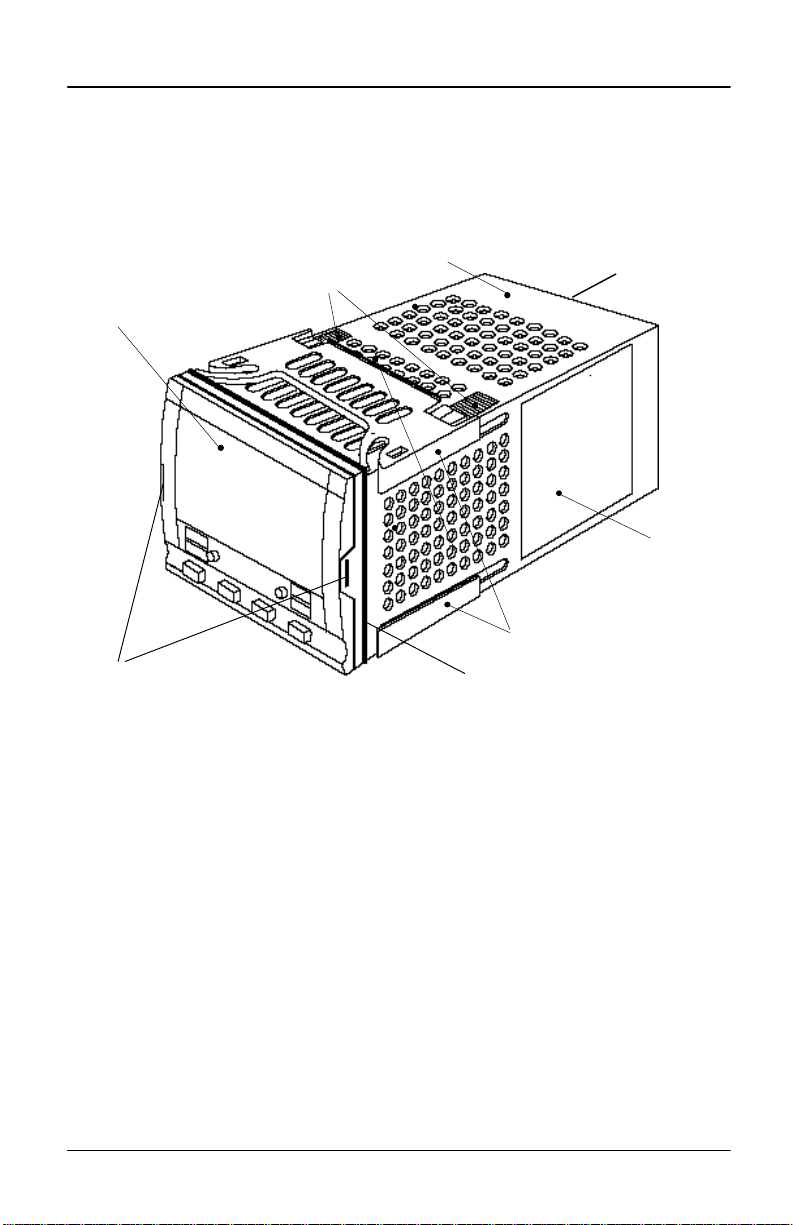
Display screen
Latching ears
Ratchets
AACC 2000 1/4 DIN controller
Case
Figure 1 - 3
Terminal
Label
Panel retaining clips
Panel sealing gasket
AACC 2000 Carbon Nov. 1, 1997
11
Page 12
Marathon Monitors Inc.
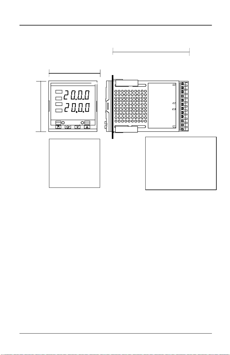
Outline dimensions Model 2000
96mm
3.78in
96mm
3.78in
Panel cut-out
92 x 92 mm
3.62 x 3.62 in
Figure 1-4 Outline dimensions Model 2000 controller
-0
+0.8
-0
+0.03
Recommended
minimum
spacing of
controllers
150mm
5.91in
The electronic assembly of the controller plugs into a rigid plastic case, which in turn fits
into the standard DIN size panel cut-out shown in Figures 1-3 and 1-4.
AACC 2000 Carbon Nov. 1, 1997
12
Page 13

Marathon Monitors Inc.
Introduction
Model AACC 2000’s are high stability, process controllers with self and adaptive tuning.
They have a modular hardware construction which accepts up to three plug-in Input/Output
modules and two interface modules to satisfy a wide range of control requirements. Two
digital inputs and an optional alarm relay are included as part of the standard hardware.
Before proceeding, please read the, Safety and EMC Information.
Controller labels
The labels on the sides of the controller identify the ordering code, the serial number, and
the wiring connections.
Appendix A, Understanding the Ordering Code, explains the hardware and software
configuration of your particular controller.
MECHANICAL INSTALLATION
To install the controller
1. Prepare the control panel cut-out to the size shown in Figure 1-3, or 1-4.
2. Insert the controller through the panel cut-out.
3. Spring the upper and lower panel retaining clips into place. Secure the controller in
position by holding it level and pushing both retaining clips forward.
Note: If the panel retaining clips subsequently need removing, in order to extract the
controller from the control panel, they can be unhooked from the side with either your
fingers, or a screwdriver.
Unplugging and plugging-in the controller
If required, the controller can be unplugged from its case by easing the latching ears
outwards and pulling it forward out of the case. When plugging the controller back into its
case, ensure that the latching ears click into place in order to secure the IP65 sealing.
AACC 2000 Carbon Nov. 1, 1997
13
Page 14
Marathon Monitors Inc.
All electrical connections are made to the screw terminals at the rear of the controller. If
you wish to use crimp connectors, the correct size is AMP part number 349262-1. They
accept wire sizes from 0.5 to 1.5 mm2 (16 to 22 AWG). A set of connectors is supplied with
the controller. The terminals are protected by a clear plastic hinged cover to prevent hands,
or metal, making accidental contact with live wires.
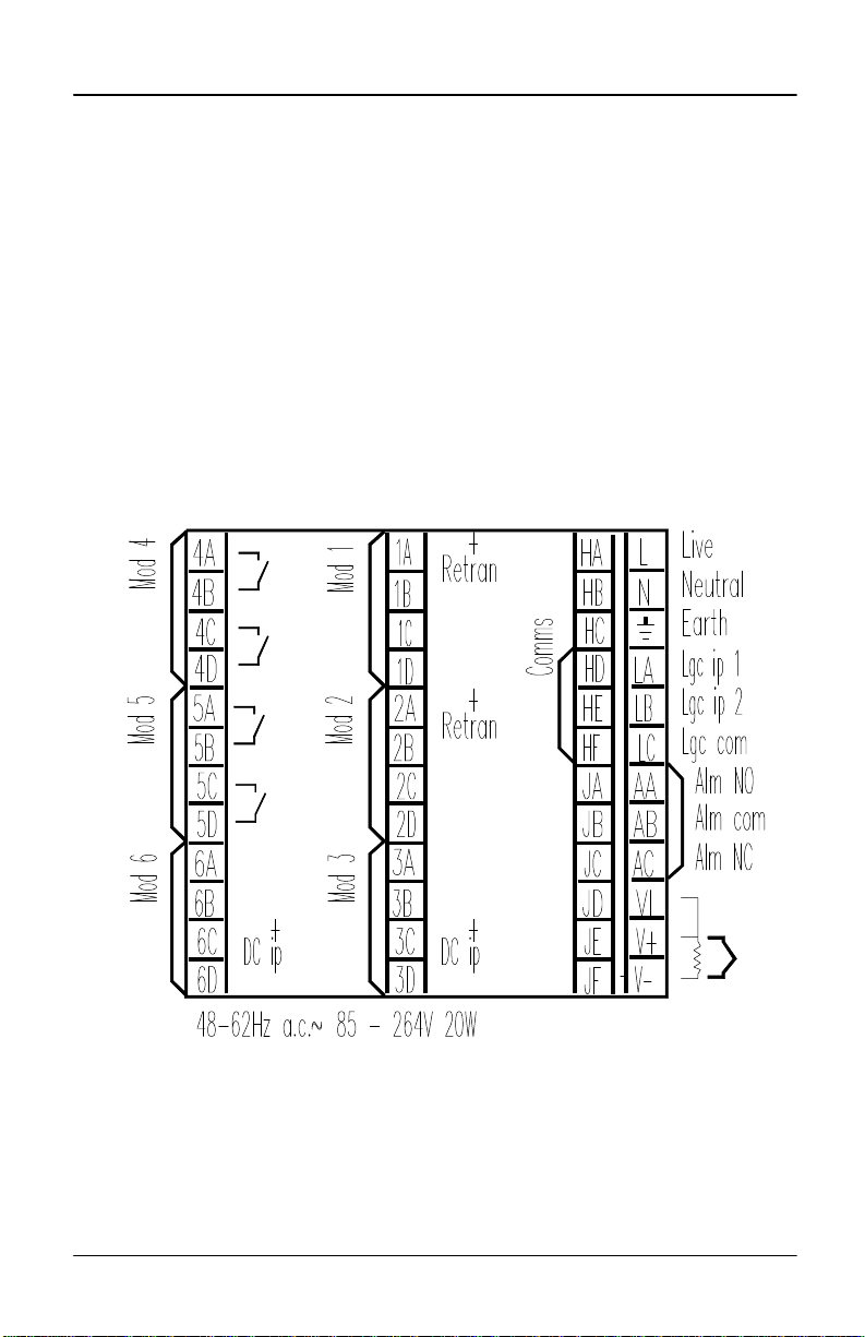
Rear terminal layouts
The rear terminal layouts are shown in Figure 1-6. The right-hand column carries the
connections to the power supply, digital inputs 1 and 2, alarm relay and sensor input. The
second and third columns from the right carry the connections to the plug-in modules. The
connections depend upon the type of module installed, if any. To determine which plug-in
modules are fitted, refer to the ordering code and wiring data on the controller side labels.
Model AACC 2000 rear terminal layout
Figure 1-6 Rear terminal layout
AACC 2000 Carbon Nov. 1, 1997
14
Page 15
Marathon Monitors Inc.
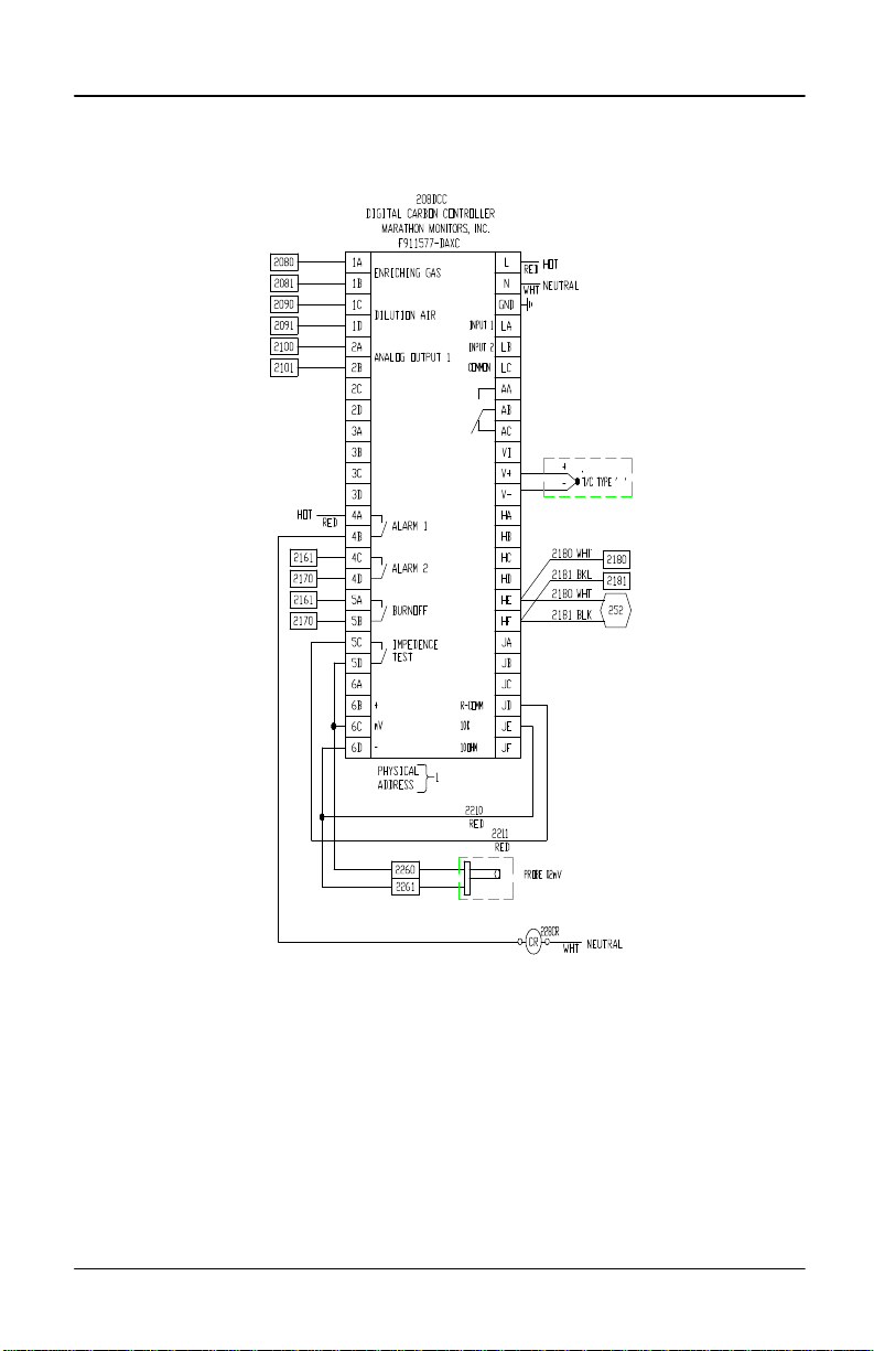
The display below shows a typical wiring diagram for the AACC2000
Carbon Controller:
Typically a series of letters appear after the part number, see chart below.
D – Dual Relay
A – Analog Output
X – Not Installed
C – Communications
I – Analog Input (typically in position 3)
AACC 2000 Carbon Nov. 1, 1997
15
Page 16

Marathon Monitors Inc.
P
V
Sensor input connections
The connections for the various types of sensor input are shown below.
Thermocouple
V1
V+
v-
PLUG-IN MODULE CONNECTIONS
Module 1, 2 and 3
Module positions 1, 2 and 3 are plug-in modules. They can be either two terminal modules
of the types shown in Table 1-1, or four terminal modules of the types shown in Table 1-2.
The tables show the connections to each module and the functions that they can perform.
Resistance
thermometer
V1
V+
v-
Fig 1-7 Sensor input connections
mA input Volts or mV inputs
V1
V+
v-
2.49Ω
current
sense
resistor
V1
V+
v-
AACC 2000 Carbon Nov. 1, 1997
16
Page 17
Marathon Monitors Inc.
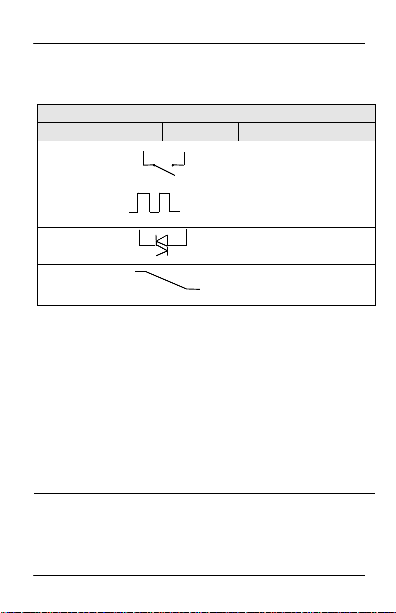
Two terminal modules
Note: Module 1 is connected to terminals 1A and 1B
Module 2 is connected to terminals 2A and 2B
Module 3 is connected to terminals 3A and 3B.
Terminal identity
Module type A B C D Possible functions
Relay: 2-pin
(2A, 264 Vac max.)
Logic - non-isolated
(18Vdc at 20mA)
Triac
(1A, 30 to 264Vac)
DC output:
- non-isolated
(10Vdc, 20mA max.)
++
−−
Line Load
++ −
Table 1-1 Two terminal module connections
Unused Heating, cooling, alarm,
program event, valve raise,
or valve lower
Unused Heating, cooling, mode 1,
mode 2, program event
Unused Heating, cooling, program
event, valve raise, or valve
lower
Unused Heating, or cooling, or
retransmission of PV,
setpoint, or control output
Snubbers
The relay and triac modules have an internal 15nF/100Ω ‘snubber’ connected across their
output, which is used to prolong contact life and to suppress interference when switching
inductive loads, such as mechanical contactors and solenoid valves.
WARNING
When the relay contact is open, or the triac is off, the snubber circuit passes 0.6mA at
110Vac and 1.2mA at 240Vac. You must ensure that this current, passing through the
snubber, will not hold on low power electrical loads. It is your responsibility as the
installer to ensure that this does not happen. If the snubber circuit is not required, it
can be removed from the relay module (BUT NOT THE TRIAC) by breaking the PCB
track that runs crosswise, adjacent to the edge connectors of the module. This can be
done by inserting the blade of a small screwdriver into one of the two slots that bound
it, and twisting.
AACC 2000 Carbon Nov. 1, 1997
17
Page 18
Marathon Monitors Inc.
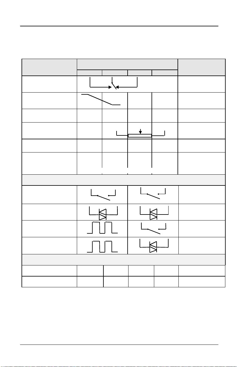
Four terminal modules
Note: Module 1 is connected to terminals 1A, 1B, 1C and 1D
Module 2 is connected to terminals 2A, 2B, 2C and 2D
Module 3 is connected to terminals 3A, 3B, 3C and 3D
Module type Terminal identity Possible functions
A B C D
lay: changeover
(2A, 264 Vac max.)
Heating, cooling,or
alarm,
DC control: Isolated
(10V, 20mA max.)
24Vdc transmitter supply
Potentiometer input
100Ω to 15KΩ
DC retransmission
DC remote input or
Process Value 2
(Module 3 only)
Dual output modules
Dual relay
(2A, 264 Vac max.)
Dual Triac
(1A, 30 to 264Vac)
Dual logic + relay
(Logic is non-isolated)
Dual Logic + triac
(Logic is non-isolated)
Triple logic input and output modules - see ratings on the next page
Triple contact input Input 1 Input 2 Input 3 Common
++ −−
+ −
+0.5Vdc
+ −
0-10Vdc RT source
(Refer to Fig. 1-8)
Line
+ −
+ −
Load
±100mV
0-20mA
Line
Line
0V
COM
Load
Load
Heating, or cooling
To power process
inputs
Motorised Valve
Position feedback
Retrans. of setpoint,
or process value
Remote Setpoint
Second PV
Heating + cooling
Dual alarms
Valve raise & lower
Heating + cooling
Valve raise & lower
Heating + cooling
Heating + cooling
Triple logic input Input 1 Input 2 Input 3 Common
Table 1-2 Four terminal module connections.
AACC 2000 Carbon Nov. 1, 1997
18
Page 19

Marathon Monitors Inc.
3D
3D
3D
3D
3D
Connections for Process Value 3 in module position 3
Thermocouple
3A
3B
3C
−
Resistance
thermometer
3A
3B
3C
Figure 1-8 Connections for Process Value 2 (PV2)
mA input
3A
3B
3C
Current
sense
resistor
2.49Ω
+
−
Volts or
mV inputs
3A
3B
3C
0-1.6Vdc
High Impedance
or mVdc
+
−
The diagrams above show the connections for the various types of input.
The input will have been configured in accordance with the ordering code.
10V inputs
+
3A
3B
0-10Vdc
3C
-
AACC 2000 Carbon Nov. 1, 1997
19
Page 20

Marathon Monitors Inc.
Communication module 1
The Models AACC 2000 will accept a plug-in communications modules.
The possible module types are shown in the table below.
The serial communications can be configured for either Modbus, or MMI protocol.
Communications module 1 Terminal identity (COMMS 1)
Module type HA HB HC HD HE HF
2-wire EIA-485 serial
communications
EIA-232 serial communications
Table 1-3 Communication module 1 connections
− − −
− − −
Common A (-) B (+)
Common Rx Tx
AACC 2000 Carbon Nov. 1, 1997
20
Page 21
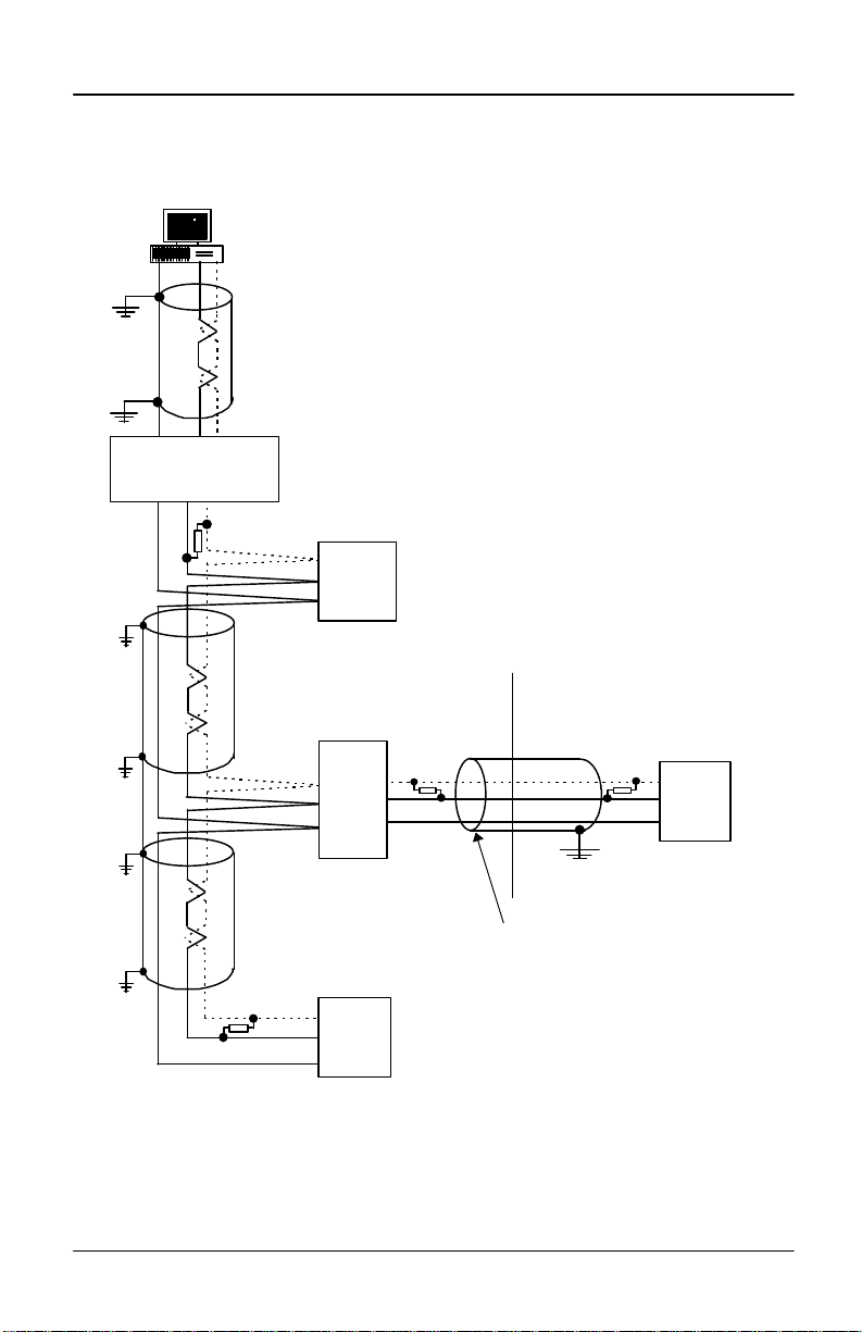
Marathon Monitors Inc.
Com
Note:
All resistors are 220 ohm 1/4W carbon composition.
Local grounds are at equipotential. Where equipotential is not available wire into
separate zones using a galvanic isolator.
Use a repeater (KD845) for more than 32 units.
ABPC
MMI Universial
RXTXCom
ComTXRX
Up to 32 S2000 controllers or
Interface Units may
be included on the network
232
ComBA
ComAB
ComAB
Com
ABLocal Earth
Area 1
ComABEFDLocal
Earth
HE-
HF+HDSeries 2000
Controller
HE-
HF+HDSeries 2000
Controller
For reasons of safety
do
not
connect to
local earth here.
Local
Earth
Local
Earth
Local
Earth
Local
Earth
Local
Earth
HE -
HF+
HD
Series 2000
Controller
Galvanic
Isolation
Barrier
Wiring of 2-wire EIA-485 serial communications link
2-wire EIA-485 is a connection which allows up to 32
controllers to be multi-dropped from a single
communications link over a distance of up to 1.2Km.
To ensure reliable operation of the communications
link, (without data corruption due to noise or line
reflections) the connections between the controller
should be made using a twisted pair of wires inside a
screened cable with the connections terminated with
resistors in the manner shown in this diagram.
Converter
Local
Ground
Zone 1
Local
Ground
Zone 1
Local
Ground
Zone 1
Local
Ground
Zone 1
Local
Ground
Zone 2
Figure 1-9 EIA-485 wiring
AACC 2000 Carbon Nov. 1, 1997
21
Page 22

Marathon Monitors Inc.
AACC 2000 Carbon Nov. 1, 1997
22
Page 23

Marathon Monitors Inc.
OPERATION
This chapter has nine topics:
• FRONT PANEL LAYOUTS
• BASIC OPERATION
• OPERATING MODES
• AUTOMATIC MODE
• MANUAL MODE
• PARAMETERS AND HOW TO ACCESS THEM
• NAVIGATION DIAGRAM
• PARAMETER TABLES
• ALARMS
AACC 2000 Carbon Nov. 1, 1997
23
Page 24
Marathon Monitors Inc.
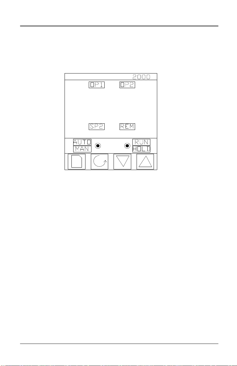
FRONT PANEL LAYOUTs
Figure 2-1 Model AACC 2000 front panel layout
26.0
20.0
Button Button Button Button
Page Scroll Down Up
AACC 2000 Carbon Nov. 1, 1997
24
Page 25
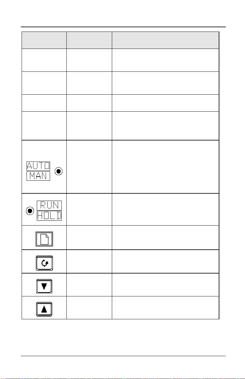
Button or
indicator
OP1
OP2
Marathon Monitors Inc.
Name Explanation
Output 1
Output 2
When lit, it indicates that the output installed in
module position 1 is on. This is normally the
heating output on a temperature controller.
When lit, it indicates that the output installed in
module position 2 is on. This is normally the
cooling output on a temperature controller.
SP2 Setpoint 2
REM Remote setpoint
Run/Hold button
When lit, this indicates that setpoint 2, (or a
setpoint 3-16) has been selected.
When lit, this indicates that a remote setpoint
input has been selected.
‘REM’ will also flash when communications is
active.
When pressed, this toggles between automatic
and manual mode:
• If the controller is in automatic mode the
Auto/Manual
button
AUTO light will be lit.
• If the controller is in manual mode, the MAN
light will be lit.
The Auto/Manual button can be disabled in
configuration level.
• Press once to start an automatic Probe care
cycle
• This RUN light indicates when ever a probe
care function is in progress
Page button Press to select a new list of parameters.
Scroll button Press to select a new parameter in a list.
Down button Press to decrease a value in the lower readout.
Up button Press to increase a value in lower readout.
Figure 2-3 Controller buttons and indicators
AACC 2000 Carbon Nov. 1, 1997
25
Page 26
Marathon Monitors Inc.
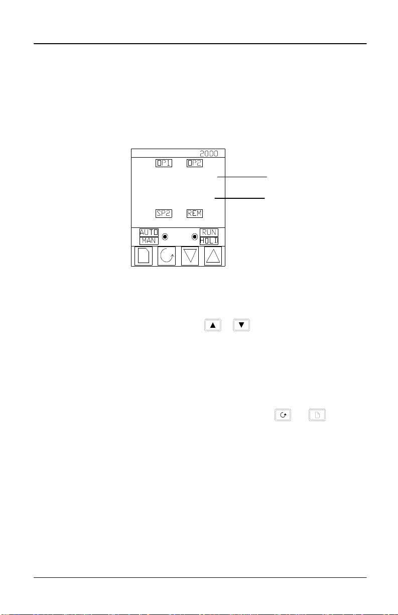
Basic operation
Switch on the power to the controller. It runs through a self-test sequence for about three
seconds and then shows the process value, in the upper readout and the setpoint, in the
lower readout. This is called the Home display.
26.0
20.0
Figure 2-4 Home display
You can adjust the setpoint by pressing the or buttons. Two seconds after
releasing either button, the display blinks to show that the controller has accepted the
new value.
OP1 will light whenever output 1 is ON. This is normally the heating output when used
as a temperature controller.
OP2 will light whenever output 2 is ON. This is normally the cooling output when used
as a temperature controller.
Note: You can get back to this display at any time by pressing and together.
Alternatively, you will always be returned to this display if no button is pressed for 45
seconds, or whenever the power is turned on.
Process Value (PV)
Setpoint
Alarms
If the controller detects an alarm condition, it flashes an alarm message in the Home
display. For a list of all the alarm messages, their meaning and what to do about them,
see Alarms at the end of this chapter.
AACC 2000 Carbon Nov. 1, 1997
26
Page 27

Marathon Monitors Inc.
Operating modes
The controller has two basic modes of operation:
• Automatic mode in which the output is automatically adjusted to maintain the
temperature or process value at the setpoint.
• Manual mode in which you can adjust the output independent of the setpoint.
You toggle between the modes by pressing the AUTO/MAN button. The displays which
appear in each of these modes are explained in this chapter.
AACC 2000 Carbon Nov. 1, 1997
27
Page 28
Marathon Monitors Inc.
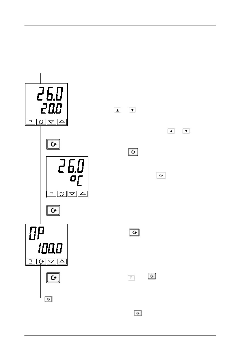
Automatic mode
You will normally work with the controller in automatic mode. If the MAN light is on,
press the AUTO/MAN button to select automatic mode. The AUTO light comes on
Power on
x 2
The Home display
Check that the AUTO light is on.
The upper readout shows the measured
temperature.
The lower readout shows the setpoint.
To adjust the setpoint up or down, press
or .
(Note: If Setpoint Rate Limit has been
enabled, then the lower readout will show
the active setpoint. If or is pressed,
it will change to show and allow
adjustment of, the target setpoint.)
Press once
Display units
A single press of will flash the
display units for 0.5 seconds, after which
you will be returned to the Home display.
Flashing of the display units may have
been disabled in configuration in which
case a single press will take you straight to
the display shown below.
Press twice
% Output power demand
The % output power demand is displayed
in the lower readout. This is a read-only
value. You cannot adjust it.
Press and together to return to the
Home display.
Pressing from the Output Power display may access further parameters. These may
be in this scroll list if the ‘Promote’ feature has been used (see Chapter 3, Access Level).
When you reach the end of this scroll list, pressing will return you to the Home
display.
AACC 2000 Carbon Nov. 1, 1997
28
Page 29
Marathon Monitors Inc.
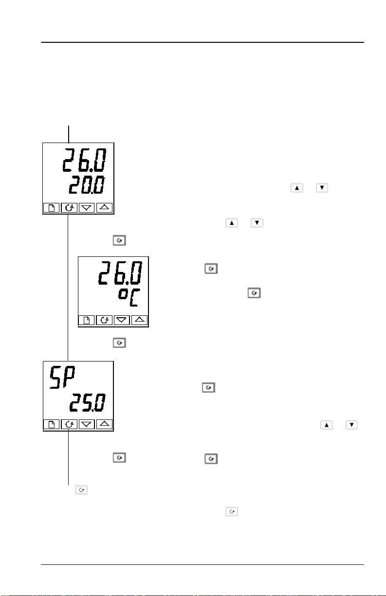
MANUAL MODE
If the AUTO light is on, press the AUTO/MAN button to select manual mode.
The MAN light comes on.
Power on
x 2
Pressing from the Output Power display may access further parameters. These may
be in this scroll list if the ‘Promote’ feature has been used (see Chapter 3, Edit Level).
When you reach the end of this scroll list, pressing will return you to the Home
display.
The Home display
Check that the MAN light is on.
The upper readout shows the measured
temperature, or process value. The lower
readout shows the % output.
To adjust the output, press or . .
(Note: If Output Rate Limit has been enabled,
then the lower readout will show the working
output. If or . is pressed, it will
change to show and allow adjustment of, the
target output.)
Press once.
Display units
A single press of flashes the display units
for 0.5 seconds, after which you are returned
to the Home display.
Flashing of the display units may have been
disabled in configuration, in which case a
single press will take you straight to the
display shown below.
Press twice.
Setpoint
To adjust the setpoint value, press or .
Press .
AACC 2000 Carbon Nov. 1, 1997
29
Page 30
Marathon Monitors Inc.
PARAMETERS AND HOW TO ACCESS THEM
Parameters are settings, that determine how the controller will operate. For
example, alarm setpoints are parameters that set the points at which alarms will
occur. For ease of access, the parameters are arranged in lists as shown in the
navigation diagram on Pages 2-10 and 2-11. The lists are:
Home list
Probe list
Care list
User list
Alarm list
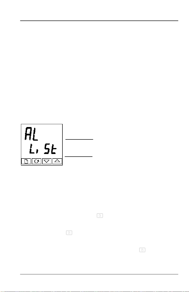
Each list has a ‘List Header’ display.
List header displays
Figure 2-5 Typical list header
display
A list header can be recognized by the fact that it always shows ‘LiSt’ in the
lower readout. The upper readout is the name of the list. In the above example,
‘AL’ indicates that it is the Alarm list header. List header displays are readonly.
To step through the list headers, press . Depending upon how your controller
has been configured, a single press may momentarily flash the display units. If
this is the case, a double press will be necessary to take you to the first list
header. Keep pressing to step through the list headers, eventually returning
you to the Home display.
To step through the parameters within a particular list, press . When you
reach the end of the list, you will return to the list header. From within a list you
Autotune list
PID list
Motor list
Setpoint list
Input list
List name
Always displays LiST
Output list
Communications
list
Information list
Access list.
AACC 2000 Carbon Nov. 1, 1997
30
Page 31

Marathon Monitors Inc.
can return to the current list header at any time can by pressing . To step to
the next list header, press once again.
AACC 2000 Carbon Nov. 1, 1997
31
Page 32

Marathon Monitors Inc.
Parameter names
In the navigation diagram, each box shows the display for a selected parameter.
The Operator parameter tables, later in this chapter, list all the parameter names
and their meanings.
The navigation diagram shows all the parameters that can, potentially, be
present in the controller. In practice, a limited number of them appear, as a
result of the particular configuration.
The shaded boxes in the diagram indicate parameters that are hidden in normal
operation. To view all the available parameters, you must select Full access
level. For more information about this, see Chapter 3, Access Levels.
Parameter displays Each list has a ‘List Header’ display.
Parameter displays
Figure 2-6 Typical parameter display
Parameter displays show the controller’s current settings. The layout of
parameter displays is always the same: the upper readout shows the parameter
name and the lower readout its value. In the above example, the parameter name
is 1FSL (indicating Alarm 1, full scale low), and the parameter value is 10.0.
To change the value of a parameter
First, select the required parameter.
To change the value, press either or . During adjustment, single presses
change the value by one digit.
Keeping the button pressed speeds up the rate of change.
Two seconds after releasing either button, the display blinks to show that the
controller has accepted the new value.
parameter name
parameter value
AACC 2000 Carbon Nov. 1, 1997
32
Page 33

Marathon Monitors Inc.
Navigation Diagram (Part A) (THE PARAMETERS THAT APPEAR DEPEND UPON
HOW THE CONTROLLER HAS BEEN CONFIGURED)
Home
List
20.0
20.0
OP
100.0
m-A
Auto
rEF
1
Probe
List
Prob
LIST
PF
0.1
OFFS
0.01
H-CO
10.0
Ptc
10
Pmu
10
AIin
10
Care
List
CArE
LIST
Care
Prt.r
0.0
tmin
0.1
Pti
1OFF
imp.h
10.0
Ptrt
10.0
bot
15.0
bort
10.0
FDE
5.0
t2C
0.0
imP.r
0.0
User
List
USEr
LIST
n1
0.1
n2
0.1
n3
0.1
n4
0.1
n5
0.1
n15
0.1
Alarm
List
AL
LIST
1---
1
2---
1
3---
1
4---
1
HY 1
1
HY 2
1
HY 3
1
HY 4
1
Lbt
OFF
diAG
no
AACC 2000 Carbon Nov. 1, 1997
33
Page 34

Autotune
List
Atu
n
tunE
OFF
Adc
mAn
PID
List
Pid
LiSt
G.SP
500
SEt
PID.1
Pb
5
Ti
300
Td
60.0
rES
0.0
Hcb
Auto
Lcb
Auto
rEL
Pb2
10
Marathon Monitors Inc.
Ti.2
300
Td.2
500
rES.2
0.0
Hcb2
Auto
Lcb2
Auto
rEL.2
1.00
FF.Pb
0.0
FF.du
100.0
Motor
List
mtr
LiSt
tm
30.0
In.t
OFF
bAcT
OFF
mP.T
Auto
U.br
DWn
Setpoint
List
SP
LiSt
SSEL
SP 1
SP 1
20.0
SP 2
0.0
SPL
0.0
SPH
100.0
SP2L
0.0
SP2H
100.0
SPrr
OFF
HbtY
OFF
AACC 2000 Carbon Nov. 1, 1997
34
Page 35

Marathon Monitors Inc.
Input
List
iP
LiSt
FiLT
OFF
FLt.2
1P.1
PU.1P
OFF
FLT.3
OFF
CAL
FACT
ofs1
0F
ofs2
0
mv.1
0
mv.2
0
mv.3
0
cjc1
0
L1.1
0
L1.2
0
L1.3
0
PVSL
1P1
Output
List
oP
LiSt
OP.Lo
0.0
OP.Hi
100.0
OPrr
OFF
FOP
0.0
CYC.1
20.0
hYS.1
1.0
onT.1
Auto
CYC.2
5.0
hYS.2
1.0
onT.2
Auto
db
0.0
Sb.OP
100.0
Comms
List
cmS
LiSt
Addr
1
Information
List
inF
o
diSP
STD
LoG.L
0.0
LoG.H
100.0
LoG.A
50.0
LoG.T
100.0
LoG.u
0.0
rES.L
no
mCT
0
w.OP
0.0
FF.OP
0
AACC 2000 Carbon Nov. 1, 1997
35
Page 36

P OP
19
1 OP
10
d OP
1.
Access
List
ACCS
LiST
codE
PASS
GoTo
OPEr
Page 37

Marathon Monitors Inc.
PARAMETER TABLES
Name Description
Home list
Home Measured value and Setpoint
OPOP
SPSP
m-Am-A
reFreF
+ Extra parameters, if the ‘Promote’ feature has been used (see Chapter 3, Edit
Level).
Name Description
ProbProb
PFPF
OFFSOFFS
H-COH-CO
PTcPTc
PmuPmu
AinAin
Name Description
CareCare
CareCare
PrtrPrtr
TminTmin
PTiPTi
imp.Himp.H
PtrtPtrt
botbot
bortbort
FdEFdE
t2Ct2C
imp.rimp.r
% Output level
Target setpoint (if in Manual mode )
Auto-man select
Customer defined identification number
Probe list
Process Factor
Millivolt input OFFSET
Hydrogen or CO constant
Probe Temperature
Probe millivolts
AUX input
Care list
Probe care operation selection
MMI actual Probe recovery time
Minimum temperature for care procedure
Probe care cycle time
Maximum probe impedance
Impedance test recovery time
Burn off time
Burn off recovery time
Final delay time
Time to next care
impedance test result
AACC 2000 Carbon Nov. 1, 1997
37
Page 38

Marathon Monitors Inc.
Name Description
UserUser
n1n1
n2n2
n3n3
n4n4
n5-15n5-15
Name Description
ALAL
11 -- -- --
22 -- -- --
33 -- -- --
44 -- -- --
In place of dashes, the last three characters indicate the alarm type. See alarm types
table:
HYHY 11
HYHY 22
HYHY 33
HYHY 44
LbLb tt
diAGdiAG Enable Diagnostic alarms ‘no’ / ‘YES’
-FSL-FSL
-FSH-FSH
--dEvdEv
--dHidHi
--dLodLo
--LCrLCr
--HCrHCr
-FL2-FL2
-FH2-FH2
-LOP-LOP
-HOP-HOP
-LSP-LSP
-HSP-HSP
4rAt4rAt
AtunAtun
User list
user parameter #1
user parameter #2
user parameter #3
user parameter #4
user parameter #5 - 15
Alarm list
Alarm 1 setpoint value
Alarm 2 setpoint value
Alarm 3 setpoint value
Alarm 4 setpoint value
Alarm 1 Hysteresis (display units)
Alarm 2 Hysteresis (display units)
Alarm 3 Hysteresis (display units)
Alarm 4 Hysteresis (display units)
Loop Break Time in minutes
Alarm types table
PV Full scale low alarm
PV Full scale high alarm
PV Deviation band alarm
PV Deviation high alarm
PV Deviation low alarm
Load Current low alarm
Load Current high alarm
Input 2 Full Scale low alarm
Input 2 Full Scale high alarm
Working Output low alarm
Working Output high alarm
Working Setpoint low alarm
Working Setpoint high alarm
Rate of change alarm (AL 4 only)
Autotune list
AACC 2000 Carbon Nov. 1, 1997
38
Page 39

Marathon Monitors Inc.
tunEtunE
drAdrA
drA.tdrA.t
AdcAdc
One-shot autotune enable
Adaptive tune enable
Adaptive tune trigger level in display units. Range = 1 to 9999
Automatic Droop Compensation (PD control only)
AACC 2000 Carbon Nov. 1, 1997
39
Page 40

Marathon Monitors Inc.
Name Description
PidPid
G.SPG.SP
SEtSEt ‘Pid.1’ or ‘Pid.2’ selected
PbPb Proportional Band (SEt 1)
titi Integral Time in secs(SEt 1)
tdtd Derivative Time in secs (SEt 1)
rESrES Manual Reset (%) (SEt 1)
HcbHcb Cutback High (SEt 1)
LcbLcb Cutback Low (SEt 1)
rEL.CrEL.C Relative Cool Gain (SEt 1)
Pb2Pb2 Proportional Band (SEt 2)
ti2ti2 Integral Time in secs(SEt 2)
td2td2 Derivative Time in secs (SEt 2)
rES.2rES.2 Manual Reset (%) (SEt 2)
Hcb2Hcb2 Cutback High (SEt 2)
Lcb2Lcb2 Cutback Low (SEt 2)
rEL.2rEL.2 Relative Cool Gain (SEt 2)
The following three parameters are used for cascade control. If this facility is not
being used, then they can be ignored.
FF.PbFF.Pb
FF.trFF.tr
FF.dvFF.dv PID feedforward limits ± %
mtrmtr
tm
In.t
bAc.t
mp.t
U.br
PID list
If Gain Scheduling has been enabled (see Chapter 4), this parameter sets
the PV below which ‘Pid.1’ is active and above which ‘Pid.2’ is active.
(in display units)
SP, or PV, feedforward propband
Feedforward trim %
Motor list - see Table 4-3
Valve travel time in seconds
Valve inertia time in secs
Valve backlash time in secs
Minimum ON time of output pulse
Valve sensor break strategy
AACC 2000 Carbon Nov. 1, 1997
40
Page 41

Marathon Monitors Inc.
Name Description
SPSP
SSEL Select SP 1 to SP16, depending on configuration
SP 1
SP 2
SP L
SP H
SP2.L
SP2.H
SPrr
Hb.ty Holdback Type for setpoint rate limit (OFF, Lo, Hi, or bAnd)
iPiP
FiLt
FLt.2
PV.ip Selects ‘ip.1’ or ‘ip.2’
FLt.3
CAL
OFS.1
OFS.2
mV.1
mV.2
mV.3
CJC.1
CJC.2
Li.1
Li.2
Li.3
PV.SL
Setpoint list
Setpoint one value
Setpoint two value
Setpoint 1 low limit
Setpoint 1 high limit
Setpoint 2 low limit
Setpoint 2 high limit
Setpoint Rate Limit
Input list
IP1 filter time constant (0.0 - 999.9 seconds).
IP2 filter time constant (0.0 - 999.9 seconds).
DC input Filter Time Constant
User Calibration Enable
simple offset
PV2 simple offset
ADC Converter millivolts
ADC Converter millivolts PV2
Second PV millivolts input
IP1 cold junction temp. reading
IP2 cold junction temp. reading
IP1 linearised value
IP2 linearised value
DC Input 3
Current Input or Inputs used for PV
AACC 2000 Carbon Nov. 1, 1997
41
Page 42

Marathon Monitors Inc.
Name Description
oPoP
Does not appear if Motorised Valve control configured.
OP.Lo
OP.Hi
OPrr
FOP
CYC.H
hYS.H
ont.H
CYC.C
hYS.C
ont.C
HC.db
Sb.OP
cmScmS
Addr
inFoinFo
diSP
LoG.L
LoG.H
LoG.A
Log.t
Log.v
Output list
Low power limit (%)
High power limit (%)
Output Rate Limit (% per sec)
Forced output level (%)
Heat cycle time (0.2S to 999.9S)
Heat hysteresis (display units)
Heat output min. on-time (secs)
Auto (0.05S), or 0.1 - 999.9S
Cool cycle time (0.2S to 999.9S)
Cool hysteresis (display units)
Cool output min. on-time (secs)
Auto (0.05S), or 0.1 - 999.9S
Heat/cool deadband (display units)
Sensor Break Output Power (%)
Comms list
Communications Address
Information list
Configure lower readout of Home display to show:
VPoS Valve position
Std Standard - display setpoint
AmPS Load current in amps
OP Output
Stat Program status
PrG.t Program time remaining in hours
Li 2 Process value 2
rAt Ratio setpoint
PrG Selected program number
rSP Remote setpoint
PV minimum
PV maximum
PV mean value
Time PV above Threshold level
PV Threshold for Timer Log
AACC 2000 Carbon Nov. 1, 1997
42
Page 43

Marathon Monitors Inc.
Name Description
Information list - continued
inFoinFo
rES.L
mCt
w.OP
FF.OP
VO
P OP
I OP
d OP
codE
Goto Goto level - OPEr, FuLL, Edit or conF
ConF
Logging Reset - ‘YES/no’
The following set of parameters is for diagnostic purposes.
Processor utilisation factor
Working output
Feedforward component of output
PID output to motorised valve
Proportional component of output
Integral component of output
Derivative component of output
Access List
ACCSACCS
Access password
Configuration password
AACC 2000 Carbon Nov. 1, 1997
43
Page 44

Marathon Monitors Inc.
Alarms
Alarm annunciation
Alarms are flashed as messages in the Home display. A new alarm is displayed as a
double flash followed by a pause, old (acknowledged) alarms as a single flash followed
by a pause. If there is more than one alarm condition, the display cycles through all the
relevant alarm messages. Table 2-1 and Table 2-2 list all of the possible alarm messages
and their meanings.
Alarm acknowledgement and resetting
Pressing both and at the same time will acknowledge any new alarms and reset
any latched alarms.
Alarm modes
Alarms will have been set up to operate in one of several modes, either:
• Non-latching, which means that the alarm will reset automatically when the Process
Value is no longer in the alarm condition.
• Latching, which means that the alarm message will continue to flash even if the
alarm condition no longer exists and will only clear when reset.
• Blocking, which means that the alarm will only become active after it has first
entered a safe state on power-up.
Alarm types
There are two types of alarm: Process alarms and Diagnostic alarms.
Process alarms
These warn that there is a problem with the process which the controller is trying to
control.
Alarm
Display
_FSL*
_FSH*
_dEv*
_dHi*
_dLo*
_LCr*
p.FLt
What it means
PV Full Scale Low alarm
PV Full Scale High alarm
PV Deviation Band alarm
PV Deviation High alarm
PV Deviation Low alarm
Load Current Low alarm
Probe impedance test
fault.
* In place of the dash, the first character will indicate the alarm number.
Alarm
Display
_FL2*
_FH2*
_LOP*
_HOP*
_LSP*
What it means
Input 2 Full Scale Low
alarm
Input 2 Full Scale High
alarm
Working Output Low
alarm
Working Output High
alarm
Working Setpoint Low
alarm
Table 2-1 Process alarms
AACC 2000 Carbon Nov. 1, 1997
44
Page 45

Marathon Monitors Inc.
Diagnostic alarms
These indicate that a fault exists in either the controller or the connected devices.
Display
shows
EE.ErEE.Er
S.brS.br
L.brL.br
Hw.ErHw.Er
no.iono.io
rmt.Frmt.F
LLLLLLLL
HHHHHHHH
Err1Err1
Err2Err2
Err3Err3
Err4Err4
Err5Err5
What it means What to do about it
Electrically Erasable Memory
Error:
The value of an operator, or
configuration, parameter has
been corrupted.
Sensor Break:
Input sensor is unreliable or
the input signal is out of
range.
Loop Break
The feedback loop is open
circuit.
Hardware error
This fault will automatically take you into
Configuration level. Check all of the
configuration parameters before returning
to Operator level. Once in Operator level,
check all of the operator parameters
before resuming normal operation. If the
fault persists, or occurs frequently,
contact MMI Controls.
Check that the sensor is correctly
connected.
Check that the heating and cooling
circuits are working properly.
Check that the correct modules are fitted.
Indication that a module is of
the wrong type, missing, or
faulty.
No I/O
None of the expected I/O
modules is fitted.
Remote input failure. the
remote DC input, is open or
short circuit
Out of range low reading
Out of range high reading
This error message normally occurs
when pre-configuring a controller without
installing any of the required I/O modules.
Check for open, or short circuit wiring on
the remote DC input.
Check the value of the input.
Check the value of the input.
Error 1: ROM self-test fail Return the controller for repair.
Error 2: RAM self-test fail Return the controller for repair.
Error 3: Watchdog fail Return the controller for repair.
Error 4: Keyboard failure
Stuck button, or a button was
pressed during power up.
Error 5: Faulty internal
communications.
Switch the power off and then on, without
touching any of the controller buttons.
Check printed circuit board
interconnections. If the fault cannot be
cleared, return the controller for repair.
AACC 2000 Carbon Nov. 1, 1997
45
Page 46

Marathon Monitors Inc.
Table 2-2b Diagnostic alarms
AACC 2000 Carbon Nov. 1, 1997
46
Page 47

Marathon Monitors Inc.
ACCESS LEVELS
This chapter describes the different levels of access to the operating parameters within
the controller.
There are three topics:
• THE DIFFERENT ACCESS LEVELS
• SELECTING AN ACCESS LEVEL
• EDIT LEVEL
THE DIFFERENT ACCESS LEVELS
There are four access levels:
• Operator level, which you will normally use to operate the controller.
• Full level, which is used to commission the controller.
• Edit level, which is used to set up the parameters that you want an operator to be able
to see and adjust when in Operator level.
• Configuration level, which is used to set up the fundamental characteristics of the
controller.
Access
level
Operator
Full
Edit
Configuration
Display
shows
OPEr
FuLL
Edit
conF
What you can do Password
Protection
In this level, operators can view and adjust the
value of parameters defined in Edit level (see
below).
In this level, all the parameters relevant to a
particular configuration are visible. All alterable
parameters may be adjusted.
In this level, you can determine which parameters
an operator is able to view and adjust in Operator
level. You can hide, or reveal, complete lists,
individual parameters within each list and you can
make parameters read-only or alterable. (See Edit
level at the end of this chapter).
This special level allows access to set up the
fundamental characteristics of the controller.
No
Yes
Yes
Yes
Figure 3-1 Access levels
AACC 2000 Carbon Nov. 1, 1997
47
Page 48

Marathon Monitors Inc.
SELECTING AN ACCESS LEVEL
Access to Full, Edit or Configuration levels is protected by a password to prevent
unauthorised access.
If you need to change the password, see Chapter 6, Configuration.
Access list header
Press until you reach the access list header
‘ACCS’.
Press
Password entry
The password is entered from the ‘codE’ display.
Enter the password using or . Once the
correct password has been entered, there is a two
second delay after which the lower readout will
change to show ‘PASS’ indicating that access is
now unlocked.
The pass number is set to ‘1’ when the controller is
shipped from the factory.
Note; A special case exists if the password has
been set to ‘0’. In this case access will be
permanently unlocked and the lower readout will
always show ‘PASS’.
Press to proceed to the ‘Goto’ page.
(If an incorrect password has been entered and the
controller is still ‘locked’ then pressing returns
you to the ‘ACCS’ list header.)
Access to Read-only Configuration
From this display, pressing and
together will take you into Read-Only
Configuration without entering a password.
This will allow you to view all of the
configuration parameters, but not adjust them.
If no button is pressed for ten seconds, you
will be returned to the Home display.
Alternatively, pressing and together
takes you immediately back to the Home
display
AACC 2000 Carbon Nov. 1, 1997
48
Page 49

Marathon Monitors Inc.
Alternative path if
‘conF’ selected
Level selection
The ‘Goto’ display allows you to select the
required access level.
Use and to select from the following
display codes: OPEr: Operator level
FuLL: Full level
Edit: Edit level
conF: Configuration level
Press
If you selected either ‘OPEr’, ‘FuLL’ or
‘Edit’ level you will be returned to the
‘ACCS’ list header in the level that you
chose. If you selected ‘conF’, you will get
a display showing ‘ConF’ in the upper
readout (see below).
Configuration password
When the ‘ConF’ display appears, you must
enter the Configuration password in order to
gain access to this level. Do this by
repeating the password entry procedure
described in the previous section.
The configuration password is set to ‘2’
when the controller is shipped from the
factory. If you need to change the
configuration password, see Chapter 6,
Configuration.
Press
Configuration level
The first display of configuration is shown.
See Chapter 6, Configuration, for details of
the configuration parameters.
For instructions on leaving configuration
level, see Chapter 6, Configuration.
AACC 2000 Carbon Nov. 1, 1997
49
Page 50

Marathon Monitors Inc.
Returning to Operator Level
To return to operator level from either ‘FuLL’ or ‘Edit’ level, repeat entry of the
password and select ‘OPEr’ on the ‘Goto’ display.
In ‘Edit’ level, the controller will automatically return to operator level if no button is
pressed for 45 seconds.
Edit level
Edit level is used to set which parameters you can view and adjust in Operator level. It
also gives access to the ‘Promote’ feature, which allows you to select and add (‘Promote’)
up to twelve parameters into the Home display list, thereby giving simple access to
commonly used parameters.
Setting operator access to a parameter
First you must select Edit level, as shown on the previous page.
Once in Edit level, you select a list, or a parameter within a list, in the same way as
you would in Operator, or Full, level − that is to say, you move from list header to list
header by pressing , and from parameter to parameter within each list using .
However, in Edit level what is displayed is not the value of a selected parameter, but a
code representing that parameter’s availability in Operator level.
When you have selected the required parameter, use and buttons to set its
availability in Operator level.
There are four codes:
ALtrALtr Makes a parameter alterable in Operator level.
PrOPrO Promotes a parameter into the Home display list.
rEAdrEAd Makes a parameter, or list header, read-only (it can be viewed but not altered).
HIdEHIdE Hides a parameter, or list header.
For example:
The parameter selected is Alarm 2, Full Scale Low
It will be alterable in Operator level
Hiding or revealing a complete list
To hide a complete list of parameters, all you have to do is hide the list header. If a list
header is selected, only two selections are available: rEAd and HIdE.
(It is not possible to hide the ‘ACCS’ list, which always displays the code: ‘LiSt’.)
AACC 2000 Carbon Nov. 1, 1997
50
Page 51

Marathon Monitors Inc.
Promoting a parameter
Scroll through the lists to the required parameter and choose the ‘PrO’ code. The
parameter is then automatically added (promoted) into the Home display list. (The
parameter will also be accessible, as normal, from the standard lists.) A maximum of
twelve parameters can be promoted. Promoted parameters are automatically ‘alterable’.
AACC 2000 Carbon Nov. 1, 1997
51
Page 52

Marathon Monitors Inc.
This sheet intentionally left blank
AACC 2000 Carbon Nov. 1, 1997
52
Page 53

Marathon Monitors Inc.
TUNING
Before tuning, please read Chapter 2, Operation, to learn how to select and change a
parameter.
This chapter has five topics:
• WHAT IS TUNING?
• AUTOMATIC TUNING
• MANUAL TUNING
• COMMISSIONING OF MOTORISED VALVE CONTROLLERS
• GAIN SCHEDULING
WHAT IS TUNING?
In tuning, you match the characteristics of the controller to those of the process being
controlled in order to obtain good control. Good control means:
• Stable, ‘straight-line’ control of the process variable at setpoint without fluctuation
• No overshoot, or undershoot, of the process variable setpoint
• Quick response to deviations from the setpoint caused by external disturbances,
thereby rapidly restoring the process variable to the setpoint value.
Tuning involves calculating and setting the value of the parameters listed in Table 4-1.
These parameters appear in the ‘Pid’ list.
Parameter
Proportional
band
Code
Pb
Meaning or Function
The bandwidth, in display units, over which the output power is
proportioned between minimum and maximum.
Integral time
Derivative time
High Cutback
Low cutback
Relative cool
gain
Hcb
Lcb
rEL
AACC 2000 Carbon Nov. 1, 1997
Determines the time taken by the controller to remove steady-
ti
state error signals.
Determines how strongly the controller will react to the rate-of-
td
change of the measured value.
The number of display units, above setpoint, at which the
controller will increase the output power, in order to prevent
undershoot on cool down.
The number of display units, below setpoint, at which the
controller will cutback the output power, in order to prevent
overshoot on heat up.
Only present if cooling has been configured and a module is
fitted. Sets the cooling proportional band, which equals the Pb
value divided by the rEL value.
53
Page 54

Marathon Monitors Inc.
AUTOMATIC TUNING
Two automatic tuning methods are provided in the AACC 2000:
• A one-shot tuner, which automatically sets up the initial values of the parameters
listed in Table 4-1 on the previous page.
• Adaptive tuning, which continuously monitors the error from setpoint and modifies
the PID values, if necessary.
One-shot Tuning
The ‘one-shot’ tuner works by switching the output on and off to induce an oscillation in
the measured value. From the amplitude and period of the oscillation, it calculates the
tuning parameter values.
If the process cannot tolerate full heating or cooling being applied during tuning, then the
level of heating or cooling can be restricted by setting the heating and cooling power
limits in the ‘oP’ list. However, the measured value must oscillate to some degree for the
tuner to be able to calculate values.
A One-shot Tune can be performed at any time, but normally it is performed only once
during the initial commissioning of the process. However, if the process under control
subsequently becomes unstable (because its characteristics have changed), you can retune again for the new conditions.
It is best to start tuning with the process at ambient process variable. This allows the
tuner to calculate more accurately the low cutback and high cutback values which restrict
the amount of overshoot, or undershoot.
How to tune
1. Set the setpoint to the value at which you will normally operate the process.
2. In the ‘Atun’ list, select ‘tunE’ and set it to ‘on’.
3. Press the Page and Scroll buttons together to return to the Home display. The display
will flash ‘tunE’ to indicate that tuning is in progress.
4. The controller induces an oscillation in the process variable by first turning the
heating on, and then off. The first cycle is not complete until the measured value has
reached the required setpoint.
5. After two cycles of oscillation the tuning is completed and the tuner switches itself
off.
6. The controller then calculates the tuning parameters listed in Table 4-1 and resumes
normal control action.
If you want ‘Proportional only’, ‘PD’, or ‘PI’ control, you should set the ‘ti’ or ‘td’
parameters to OFF before commencing the tuning cycle. The tuner will leave them off
and will not calculate a value for them.
AACC 2000 Carbon Nov. 1, 1997
54
Page 55

Marathon Monitors Inc.
Typical automatic tuning cycle
Process Variable
Calculation of the cutback values
Low cutback and High cutback are values that restrict the amount of overshoot, or
undershoot, that occurs during large step changes in process variable (for example, under
start-up conditions).
If either low cutback, or high cutback, is set to ‘Auto’ the values are fixed at three times
the proportional band, and are not changed during automatic tuning.
Adaptive tune
Adaptive tuning is a background algorithm, which continuously monitors the error from
setpoint and analyses the control response during process disturbances. If the algorithm
recognises an oscillatory, or under-damped, response it recalculates the Pb, ti and td
values.
Adaptive tune is triggered whenever the error from setpoint exceeds a trigger level. This
trigger level is set in the parameter ‘drA.t’, which is found in the Autotune list. The
value is in display units. It is automatically set by the controller, but can also be
manually
re-adjusted.
Setpoint
Time
Adaptive tune should be used with:
1. Processes whose characteristics change as a result of changes in the load, or setpoint.
2. Processes that cannot tolerate the oscillation induced by a One-shot tune.
Adaptive tune should not be used:
1. Where the process is subjected to regular external disturbances that could mislead the
adaptive tuner.
2. On highly interactive multiloop applications. However, moderately interactive loops,
such as multi-zone extruders, should not give a problem.
AACC 2000 Carbon Nov. 1, 1997
55
Page 56

Marathon Monitors Inc.
MANUAL TUNING
If for any reason automatic tuning gives unsatisfactory results, you can tune the controller
manually. There are a number of standard methods for manual tuning. The one
described here is the Ziegler-Nichols method.
With the process at its normal running process variable:
1. Set the Integral Time ‘ti’ and the Derivative Time ‘td’ to OFF.
2. Set High Cutback and Low Cutback, ‘Hcb’ and ‘Lcb’, to ‘Auto’.
3. Ignore the fact that the process variable may not settle precisely at the setpoint.
4. If the process variable is stable, reduce the proportional band ‘Pb’ so that the process
variable just starts to oscillate. If the process variable is already oscillating, increase
the proportional band until it just stops oscillating. Allow enough time between each
adjustment for the loop to stabilise. Make a note of the proportional band value ‘B’
and the period of oscillation ‘T’.
5. Set the Pb, ti, td parameter values according to the calculations given in Table 4-2.
Type of control Proportional
band ‘Pb’
Proportional only 2xB OFF OFF
P + I control 2.2xB 0.8xT OFF
P + I + D control 1.7xB 0.5xT 0.12xT
Table 4-2 Tuning values
AACC 2000 Carbon Nov. 1, 1997
Integral time
56
‘ti’
Derivative time
‘td’
Page 57

Marathon Monitors Inc.
Setting the cutback values
The above procedure sets up the parameters for optimum steady state control. If
unacceptable levels of overshoot or undershoot occur during start-up, or for large step
changes in process variable, then manually set the cutback parameters ‘Lcb’ and ‘Hcb’.
Proceed as follows:
1. Set the low and high cutback values to three proportional bandwidths (that is to say,
Lcb = Hcb = 3 x Pb).
2. Note the level of overshoot, or undershoot, that occurs for large atmosphere changes
(see the diagrams below).
In example (a) increase ‘Lcb’ by the overshoot value. In example (b) reduce ‘Lcb’ by
the undershoot value.
Example (a)
Atmosphere
Overshoot
Setpoint
Example (b)
Atmosphere
Setpoint
Undershoot
Time
Where the atmosphere approaches setpoint from above, you can set ‘Hcb’ in a similar
manner.
AACC 2000 Carbon Nov. 1, 1997
57
Page 58

Marathon Monitors Inc.
Integral action and manual reset
In a full three-term controller (that is, a PID controller), the integral term ‘ti’
automatically removes steady state errors from the setpoint. If the controller is set up to
work in two-term mode (that is, PD mode), the integral term will be set to ‘OFF’. Under
these conditions the measured value may not settle precisely at setpoint. When the
integral term is set to ‘OFF’ the parameter manual reset (code ‘rES’) appears in the
‘Pid LiSt’ in ‘FuLL’ level. This parameter represents the value of the power output
that will be delivered when the error is zero. You must set this value manually in order
to remove the steady state error.
Automatic droop compensation (Adc)
The steady state error from the setpoint, which occurs when the integral term is set to
‘OFF’ is sometimes referred to as ‘droop’. ‘Adc’ automatically calculates the manual
reset value in order to remove this droop. To use this facility, you must first allow the
process variable to stabilise. Then, in the autotune parameter list, you must set ‘Adc’ to
‘on’. The controller will then calculate a new value for manual reset, and switch ‘Adc’
to ‘OFF’.
‘Adc’ can be repeated as often as you require, but between each adjustment you must
allow time for the process variable to stabilise.
AACC 2000 Carbon Nov. 1, 1997
58
Page 59

Marathon Monitors Inc.
Motorized valve control
The AACC 2000 can be configured for motorised valve control as an alternative to the
standard PID control algorithm. This algorithm is designed specifically for positioning
motorised valves.
These are ordered pre-configured as Model numbers:
• 2000/VC motorised valve controllers
• 2000/VP motorised valve controllers with a single setpoint programmer
• 2000/V4 motorised valve controllers storing four setpoint programs.
• 2000/VM motorised valve controllers storing twenty setpoint programs.
Figure 1-11 in Chapter 1 shows how to connect a motorised valve controller. The control
is performed by delivering open, or close, pulses in response to the control demand
signal.
The motorised valve algorithm can operate in one of three ways:
1. The so-called boundless mode, which does not require a position feedback
potentiometer for control purposes; although one can be connected and used purely to
display the valve’s position.
2. Bounded, (or position), control mode, which requires a feedback potentiometer.
This is closed-loop control determined by the valve’s position.
The desired control mode is selected in the ‘inst’ list in configuration level.
The following parameter list will appear in the navigation diagram shown in Chapter 2, if
your controller is configured for motorised valve control.
Name Description Values
mtrmtr
tm
In.t
bAc.t
mp.t
U.br
AACC 2000 Carbon Nov. 1, 1997
Motor list Min Max Default
Valve travel time in seconds.
This is the time taken for the valve to travel
from its fully closed position to its fully open
position.
Valve inertia time in seconds.
This is the time taken for the valve to stop
moving after the output pulse is switched off.
Valve backlash time in seconds.
This is the minimum on-time required to
reverse the direction of the valve. i.e. the
time to overcome the mechanical backlash.
Output pulse minimum on-time, in seconds.
Valve sensor break strategy.
59
0.1 240.0 30.0
OFF 20.0 OFF
OFF 20.0 OFF
Auto 100.0 Auto
rESt, uP, dwn dwn
Page 60

Marathon Monitors Inc.
COMMISSIONING THE MOTORISED VALVE CONTROLLER
The commissioning procedure is the same for both bounded and boundless control modes,
except in bounded mode you must first calibrate the position feedback potentiometer, as
described in the section below.
Proceed as follows:
1. Measure the time taken for the valve to be raised from its fully closed to its fully
open position and enter this as the value in seconds into the ‘tm’ parameter.
2. Set all the other parameters to the default values shown in Table 4-3.
The controller can then be tuned using any of the automatic, or manual, tuning procedures
described earlier in this chapter. As before, the tuning process, either automatic or
manual, involves setting the values of the parameters in Table 4-1. The only difference
with boundless control is that the derivative term ‘td’, although present, will have no
effect.
Adjusting the minimum on-time ‘mp.tmp.t’
The default value of 0.2 seconds is satisfactory for most processes. If, however, after
tuning the process, the valve activity is excessively high, with constant oscillation
between raise and lower pulses, the minimum on-time can be increased.
The minimum on-time determines how accurately the valve can be positioned and
therefore the control accuracy. The shorter the time, the more precise the control.
However, if the time is set too short, process noise will cause an excessively busy valve.
Inertia and backlash settings
The default values are satisfactory for most processes, i.e. ‘OFF’.
Inertia is the time taken for the valve to stop after the output pulse is turned off. If this
causes a control problem, the inertia time needs to be determined and then entered into
the parameter, ‘In.t’. The inertia time is subtracted from the raise and lower output
pulse times, so that the valve moves the correct distance for each pulse.
Backlash is the output pulse time required to reverse the direction of the valve, i.e. the
time taken to overcome the mechanical backlash of the linkages. If the backlash is
sufficient to cause a control problem, then the backlash time needs to be determined and
then entered into the parameter, ‘bac.t’.
The above two values are not part of the automatic tuning procedure and must be entered
manually.
CALIBRATING THE POSITION FEEDBACK POTENTIOMETER
Before proceeding with the feedback potentiometer calibration, you should ensure, in
configuration level, that module position 2 (2a), or 3 (3a), has its ‘id’ indicating
‘Pot.i’, (meaning Potentiometer Input). Continue to scroll down the module
AACC 2000 Carbon Nov. 1, 1997
60
Page 61

Marathon Monitors Inc.
configuration list. ‘func’ should be set to ‘Vpos’, ‘VAL.L’ must be set to ‘0’ and
‘VAL.H’ to ‘100’.
Exit from configuration and you are now ready to calibrate the position feedback
potentiometer. Proceed as follows.
1. In Operator level, press the AUTO/MAN button to put the controller in Manual mode.
2. Drive the valve to its fully open position using .
3. Press until you get to ‘ip-List’.
4. Press to get to ‘PCAL-OFF’.
5. Press or to turn ‘PCAL’ to ‘on’.
6. Press and the upper readout indicates ‘Pot’.
7. Press or to get to ‘Pot-3A.Hi’. (Assuming that the Potentiometer Input
Module is in module position 3.)
8. Press to go to ‘GO-no’.
9. Press or to see ‘GO-YES’, which starts the calibration procedure.
10. Calibration is complete when the display returns to ‘GO-no’.
11. Press and together to return directly to the Operator level.
12. The controller should still be in Manual mode.
13. Drive the valve to its fully closed position using .
14. Press until you get to ‘ip-List’.
15. Press to get to ‘PCAL-OFF’.
16. Press or to turn ‘PCAL’ to ‘on’.
17. Press and the upper readout indicates ‘Pot’.
18. Press or to get to ‘Pot-3A.Lo’
19. Press to go to ‘GO-no’.
20. Press or to see ‘GO-YES’, which starts the calibration procedure.
21. Calibration is complete when the display returns to ‘GO-no’.
22. Press and together to return directly to the Operator level.
23. Press the AUTO/MAN button to place the controller in AUTO and the calibration of
the position feedback potentiometer is now complete.
AACC 2000 Carbon Nov. 1, 1997
61
Page 62

Marathon Monitors Inc.
Gain scheduling
Gain scheduling is the automatic transfer of control between one set of PID values and
another. In the case of the AACC 2000 controllers, this is done at a presettable process
value. It is used for the more difficult to control processes which exhibit large changes
in their response time or sensitivity at, for example, high and low process variables, or
when heating or cooling.
The AACC 2000 has two sets of PID values. You can select the active set from either a
digital input, or from a parameter in the PID list, or you can transfer automatically in gain
scheduling mode. The transfer is bumpless and will not disturb the process being
controlled.
To use gain scheduling, follow the steps below:
Step1: Enable in configuration level
Gsch
Gain scheduling must first be enabled in
Configuration level. Goto the Inst Conf list,
select the parameter Gsch, and set it to YES.
YES
Step 2: Set the transfer point
G.SP
350
Step 3: Tuning
Once gain scheduling has been enabled, the
parameter G.SP will appear at the top of the
Pid list in FuLL access level. This sets the
value at which transfer occurs. PID1 will be
active when the process value is below this
setting and PID2 when the process value is
above it. The best point of transfer depends on
the characteristics of the process. Set a value
between the control regions that exhibit the
greatest change
You must now set up the two sets of PID values. The values can be
manually set, or automatically tuned as described earlier in this chapter.
When tuning automatically you must tune twice, once above the switching
point G.SP and again below the switching point. When tuning, if the
process value is below the transfer point G.SP the calculated values will
automatically be inserted into PID1 set and if the process value is above
G.SP, the calculated values will automatically be inserted into PID2 set.
AACC 2000 Carbon Nov. 1, 1997
62
Page 63

Marathon Monitors Inc.
CONFIGURATION
This chapter consists of six topics:
• SELECTING CONFIGURATION LEVEL
• LEAVING CONFIGURATION LEVEL
• SELECTING A CONFIGURATION PARAMETER
• CHANGING THE PASSWORDS
• NAVIGATION DIAGRAM
• CONFIGURATION PARAMETER TABLES.
In configuration level you set up the fundamental characteristics of the controller.
These are:
• The type of control (e.g. reverse or direct acting)
• The Input type and range
• The Setpoint configuration
• The Alarms configuration
• The Programmer configuration
• The Digital input configuration
• The Alarm Relay configuration
• The Communications configuration
• The Modules 1, 2 & 3 configuration
• Calibration
• The Passwords.
WARNING
Configuration is protected by a password and should only be carried out by a
qualified person, authorised to do so. Incorrect configuration could result in
damage to the process being controlled and/or personal injury. It is the
responsibility of the person commissioning the process to ensure that the
configuration is correct.
AACC 2000 Carbon Nov. 1, 1997
63
Page 64

Marathon Monitors Inc.
Selecting configuration level
There are two alternative methods of selecting Configuration level:
• If you have already powered up, then follow the access instructions given in Chapter
3, Access levels.
Alternatively, press and together when powering up the controller. This will
take you directly to the ‘ConF’ password display.
Password entry
When the ‘ConF’ display appears, you must enter the
Configuration password (which is a number) in order to gain
access to Configuration level.
Enter the password using the or buttons.
The configuration password is set to ‘2’ when the controller
is shipped from the factory.
Once the correct password has been entered, there is a two
second delay, after which the lower readout will change to
‘PASS’ indicating that access is now unlocked.
Note: A special case exists if the password has been set to
‘0’. In this situation, access is permanently unlocked and the
lower readout will always show ‘PASS’.
AACC 2000 Carbon Nov. 1, 1997
Press to enter configuration.
(If an incorrect password has been entered and the controller
is still ‘locked’ then pressing at this point will take you
to the ‘Exit’ display with ‘no’ in the lower readout. Simply
press to return to the ‘ConF’ display.)
You will obtain the first display of configuration.
64
Page 65

Marathon Monitors Inc.
LEAVING CONFIGURATION LEVEL
To leave the Configuration level and return to Operator level Press until the
‘Exit’ display appears.
Alternatively, pressing and together will take you directly to the ‘Exit’ display
Use or to select ‘YES’. After a twosecond delay, the display will blank and revert to
the Home display in Operator level.
SELECTING A CONFIGURATION PARAMETER
The configuration parameters are arranged in lists as shown in the navigation diagram
in
Figure 6.1.
To step through the list headers, press the Page button.
To step through the parameters within a particular list press the Scroll button.
When you reach the end of the list you will return to the list header.
You can return directly to the list header at any time by pressing the Page button.
Parameter names
Each box in the navigation diagram shows the display for a particular parameter. The
upper readout shows the name of the parameter and the lower readout its value. For a
definition of each parameter, see the Configuration Parameter Tables at the end of this
chapter. To change the value of a selected parameter, use the and buttons.
The navigation diagram shows all the lists headers and parameters that can, potentially,
be present in the controller. In practice, those actually present will vary according to
the particular configuration choices you make.
Changing the passwords
There are TWO passwords. These are stored in the Password configuration list and can
be selected and changed in the same manner as any other configuration parameter.
The password names are: ‘ACC.P’ which protects access to Full level and Edit level
‘cnF.P’ which protects access to Configuration level.
AACC 2000 Carbon Nov. 1, 1997
65
Page 66

Marathon Monitors Inc.
NAVIGATION DIAGRAM (PART A)
Instrument
List
Process
Value List
Input Config
List
Setpoint
Config
Alarms
Config
inST
LiSt
2rFn
CArB
CTrL
Pid
TYPE
ctrL
AcT
REU
cool
LIN
TiTd
SEc
Fwd.t
none
SbrT
SB.OP
FOP
no
bcd
nonE
GSch
no
PU
ConF
uniT
°C
dEc.p
nnnn
rnGL
0
rnGH
2000
iP
ConF
inPT
htc
CJC
Auto
imP
Auto
SP
ConF
nSP
2
rmTr
OFF
m.Tr
OFF
rmPU
PSEc
rmT
nonE
AL
ConF
AL1
FSH
LTch
on
bLoc
on
AL2
FSH
LTch
on
bLoc
on
dtYP
PU
m-A
D1SA
r-h
ENAB
AL3
FSH
LTch
on
bLoc
on
PwrF
AACC 2000 Carbon Nov. 1, 1997
66
Page 67

Marathon Monitors Inc.
AL4
FSH
LTch
on
bLoc
on
Logic
Config
LAb
ConF
id
LoG
Func
Man
Alarms
Config
AA
ConF
id
RELY
Func
nor
SEnS
nor
IFSH
yes
2FSL
no
Comms1
Config
Ha
ConF
id
CMS
Func
bAud
9600
PrTY
nonE
rES
FuLL
Comms2
Config
JA
ConF
id
NONE
Module1
Config
1A
ConF
id
dCrE
Func
OP1
UaL.L
0
UALH
100
uniT
mA
AL3
no
AL4
no
dELY
no
OuTL
4.0
OuTH
20.0
Plus
Event
Outputs
AACC 2000 Carbon Nov. 1, 1997
67
Page 68

Marathon Monitors Inc.
Module2
Config
2A
ConF
id
dCrE
Func
OP2
UaL.L
0
UALH
100
uniT
mA
Module3
Config
3A
ConF
id
dCrE
Func
H-CO
inPT
Hr1n
imP
off
inPL
0.0
Module4
Config
4A
ConF
id
rELY
Func
DIG
SEnS
inu
1FSH
YES
2FSL
no
Module
Config
4C
ConF
id
rELY
Func
DIG
SEnS
inu
1FSH
no
2FSL
YES
Module
Config
5A
ConF
id
rELY
Func
DIG
SEnS
nor
1FSH
no
2FSL
no
Module
Config
5C
ConF
id
rELY
Func
DIG
SEnS
nor
1FSH
no
2FSL
no
OuTL
4.0
OuTH
20.0
AACC 2000 Carbon Nov. 1, 1997
inPH
2.0
UALL
0
UALH
2000
AL3
no
AL4
no
68
AL3
no
AL4
no
AL3
no
AL4
no
imp
Yes
burn
yes
UEri
no
PFLT
no
AL3
no
AL4
no
imp
Yes
burn
yes
UEri
no
PFLT
no
Page 69

Marathon Monitors Inc.
Module
Config
6A
ConF
id
rELY
Func
PMV
inPT
HiLn
imP
Auto
inPL
-0.2
Custom
Config
CUST
ConF
in1
0.0
UAL1
0.0
in2
1.0
UAL2
200.0
in3
2.0
Calibration
Config
CAL
ConF
cAL
nonE
UCAL
NO
Pt1L
Pt1H
OF1L
0.0
Password
Config
PASS
ConF
ACCP
cnFP
Exit
Exit
inPH
1.8
UALL
-200
UALH
1800
UAL.3
350.0
OF1H
0.0
Pt2L
Pt2H
in8
7.0
OF2L
0.0
UAL.8
800.0
AACC 2000 Carbon Nov. 1, 1997
OF2H
0.0
69
Page 70

Marathon Monitors Inc.
CONFIGURATION PARAMETER TABLES
Name Description Values Meaning
inStinSt
ZrFn
CtrL
tYPE
Act
CooL
ti.td
m-A
r-h
PwrF
Fwd.t
Sbr.t
FOP
bcd
Instrument configuration
Instrument Function
Control type
Instrument USE
Control action
Type of cooling
Integral & derivative
time units
Front panel Auto/Man button
Front panel Run/Hold button
Power feedback
Feed forward type
Sensor break output
Forced manual output
BCD input function
Carb
Pid
On.OF
VP
VP b
ctrL
Mon
rEv
dir
Lin
oiL
H2O
FAn
ProP
on.OF
SEc
min
EnAb
diSA
EnAb
diSA
on
OFF
none
FEEd
SP.FF
PV.FF
Sb.OP
HoLd
no
trac
Step
none
prog
sp
% Carbon
PID control
On/off control
Boundless motorised valve
control - no feedback
required
Bounded motorised valve
control - feedback required
Controller
Monitor
Reverse acting
Direct acting
Linear
Oil (50mS minimum ontime)
Water (non-linear)
Fan (0.5S minimum ontime)
Proportional only to error
On/off cooling
Seconds, OFF to 9999
Minutes, OFF to 999.9
Enabled
Disabled
Enabled
Disabled
On
Off
None
Normal feed forward
Setpoint feed forward
PV feed forward
Go to pre-set value
Freeze output
Bumpless Auto/Manual
transfer
Returns to the Manual
value that was set when
last in Manual mode
Steps to forced output
level. Value set in ‘FOP’ of
‘op-List’ in Operator
Level
Not used
Select program number
Select setpoint number
AACC 2000 Carbon Nov. 1, 1997
70
Page 71

Marathon Monitors Inc.
gsch
pVpV
unit
dec.p
rng.l
rng.h
Gain schedule enable
Process value config
Inststrument units
Decimal places in the
displayed value
Range low Low range limit. Also setpoint limit for
Range high High range limit. Also setpoint limit for
0
C
0
F
0
k
none
nnnn
nnn.n
nn.nn
no
yes
Celsius
Farenheit
Kelvin
Display units blanked
None
One
Two
alarms and programmers
alarms and programmers
Name Description Values Meaning
iPiP
inPt
Input configuration
Input type
* see “CUST” List.
J.tc
k.tc
L.tc
r.tc
b.tc
n.tc
t.tc
S.tc
PL 2
C.tc
rtd
mV
voLt
mA
Sr V
Sr A
mV.C
V.C
mA.C
J thermocouple
K thermocouple
L thermocouple
R thermocouple (Pt/Pt13%Rh)
B thermocouple (Pt30%Rh/Pt6%Rh)
N thermocouple
T thermocouple
S thermocouple (Pt/Pt10%Rh)
PL 2 thermocouple
Custom downloaded t/c (default = type
C)
100Ω platinum resistance thermometer
Linear millivolt
Linear voltage
Linear milliamps
Square root volts
Square root milliamps
8-point millivolt custom linearisation*
8-point Voltage custom linearisation*
8-point milliamp custom linearisation*
Disabled
Enabled
Name Description Values Meaning
CJC
imp
AACC 2000 Carbon Nov. 1, 1997
Cold Junction
Compensation
Sensor Break Impedance
Auto
0oC
45oC
50oC
OFF
Off
Auto
Hi
Hi.Hi
71
Automatic internal compensation
0oC external reference
45oC external reference
50oC external reference
No cold junction compensation
Disabled (only with linear inputs)
Factory set
Impedance of input > 5KΩ
Impedance of input > 15KΩ
Page 72

Marathon Monitors Inc.
Linear Input Scaling − The next 4 parameters only appear if a linear or sq rt input is chosen.
inp.L
inp.H
Displayed Value
VAL. H
Input value low
Input value high
VAL.L
VAL.H
VAL. L
Electrical
Input
inP.HinP.L
Displayed reading low
Displayed reading high
Name Description Values Meaning
SPSP
nSP
rm.tr
m.tr
rmP.U
rmt
Setpoint configuration
Number of setpoints
Remote Tracking
Manual Track
Setpoint rate limit units
Remote setpoint configuration
2, 4, 16
OFF
trAc
OFF
trAc
PSEc
Pmin
PHr
nonE
SP
Loc.t
rmt.t
Select number of setpoints available
Disable
Local setpoint tracks remote setpoint
Disable
Local setpoint tracks PV when in
manual
Per second
Per minute
Per hour
Disable
Remote setpoint
Remote setpoint + local trim
Remote trim + local setpoint
AACC 2000 Carbon Nov. 1, 1997
72
Page 73

Marathon Monitors Inc.
Alarm configuration Values
ALAL
The controller contains four ‘soft’ alarms, which are configured in this list. Once configured,
they can be attached to a physical output as described in the alarm relay configuration list,
‘AA Conf’.
Alarm 1 Type
AL1
Latching
Ltch
Blocking
bLoc
Alarm 2 Type
AL2
Latching
Ltch
Blocking
bLoc
Alarm 3 Type
AL3
Latching
Ltch
Blocking
bLoc
Alarm 4 Type
AL4
Latching
Ltch
Blocking (not if ‘AL4’ = ‘rAt’)
bLoc
Table A - Alarm types
Value Alarm type
OFF
FSL
FSH
dEv
dHi
dLo
LCr
HCr
FL2
FH2
LOP
HOP
LSP
HSP
rAt
Alarm Modes
‘no’ means that the alarm will be non-latching.
‘YES’ means that the alarm will be latched, with automatic resetting. Automatic resetting means that if a
reset is actioned before the alarm has cleared, then it will automatically reset when it clears
No alarm
PV Full scale low
PV Full scale high
PV Deviation band
PV Deviation high
PV Deviation low
Load Current low
Load Current high
Input 2 Full Scale low
Input 2 Full Scale high
Working Output low
Working Output high
Working Setpoint low
Working Setpoint high
PV Rate of change
AL4 only
see Table A
no/YES/Evnt/mAn*
no/YES
see Table A
no/YES/Evnt/mAn*
no/YES
see Table A
no/YES/Evnt/mAn*
no/YES
see Table A
no/YES/Evnt/mAn*
no/YES
AACC 2000 Carbon Nov. 1, 1997
73
Page 74

Marathon Monitors Inc.
Name Description Values Meaning
LALA
id
Func
Digital input 1 configuration Action on contact closure
Identity
Function of input
The function is active
when the input has a contact
closure to the common
terminal - LC
These BCD inputs are used to
select either a program number
or the setpoint number
according to the setting of the
parameter ‘bcd’ in the ‘inSt’ bcd.5
configuration list
LoG.i
nonE
mAn
rmt
SP.2
Pid.2
ti H
tunE
drA
Ac.AL
AccS
Loc.b
uP
dwn
ScrL
PAGE
bcd.1
bcd.2
bcd.3
bcd.4
bcd.6
Stby
PV.SL
IMP
Logic input
No function
Manual mode select
Remote setpoint select
Setpoint 2 select
PID set 2 select
Integral hold
One-shot self-tune enable
Adaptive tune enable
Acknowledge alarms
Select Full access level
Keylock
Simulate pressing of the
button
Simulate pressing of the
button
Simulate pressing of the
button
Simulate pressing of the
button
Least significant BCD digit
2nd BCD digit
3rd BCD digit
4th BCD digit
5th BCD digit
Most significant BCD digit
Standby - ALL control outputs
turned OFF (alarm Outputs are
not affected)
PV Select:
Closed = PV1 / Open = PV2
Initiate Impedance test
Lb Digital input 2 configuration Action on contact closure
As per Digital input 1 configuration
AACC 2000 Carbon Nov. 1, 1997
74
Page 75

Marathon Monitors Inc.
Name Description Values Meaning
AAAA
id
Func
SEnS
The following digital events appear after ‘SEnS’. Any one, or more, of the events can be
combined on to the output (see Fig. 6-2) by selecting ‘YES’ in the lower readout.
1 - - 2 - - -
3 - - -
4 - - -
mAn
Sbr
SPAn
Lbr
Ld.F
tunE
dc.F
rmt.F
iP1.F
IMP
burn
VERi
VFLT
PFLT
nw.AL
End
SYnc
Alarm relay configuration
Identity
Function
Digital output sense
Alarm 1 active
Alarm 2 active
Alarm 3 active
Alarm 4 active
Controller in manual mode
Sensor break
PV out of range
Loop break
Load failure alarm
Tuning in progress
Voltage output open circuit, or mA
output open circuit
module connection open circuit
Input 1 Failure
Impedance test in progress
Probe burn off in progress
Probe verification in progress
Verification Fault
Probe Fault
New Alarm has occurred
End of setpoint rate limit, or end of
program
Program Synchronisation active
rELy
nonE
dIG
nor
inv
YES / no (- - -) = alarm type (e.g. FSL).
YES / no
YES / no in ‘AL ConF’ list, then display
YES / no differ:- e.g. Alarm 1 = ‘AL 1’.
YES / no
YES / no
YES / no
YES / no
YES / no
YES / no
YES / no
YES / no
YES / no
YES / no
YES / no
Relay output
No function
Digital output
Normal (output energises when
TRUE, e.g. program events)
Inverted (output de-energises
when TRUE, e.g. alarms)
If an alarm has not been
configured
will
AACC 2000 Carbon Nov. 1, 1997
75
Page 76

Marathon Monitors Inc.
SEnS
Digital Events
OR
Figure 6-2 Combining several digital events on to one output
dIG
nor
inv
Output
Module
Name Description Values Meaning
HAHA
id
Comms 1 module config
Identity of the module installed
cmS
2-wire EIA-485
For ‘idid’ = ‘cms’ (Digital communications) use this parameter table:
Func
bAud
dELy
Prty
The following parameters only appear if the function chosen is Modbus protocol.
rES
Function
Baud Rate
Delay - quiet period, required by
some comms
adaptors
Comms Parity
Comms Resolution
mod
mAr
1200, 2400, 4800, 9600,
19.20(19,200)
no
YES
nonE
EvEn
Odd
FuLL
Int
Modbus protocol
Marathon Monitors protocol
No delay
Delay active - 10mS
No parity
Even parity
Odd parity
Full resolution
Integer resolution
AACC 2000 Carbon Nov. 1, 1997
76
Page 77

Marathon Monitors Inc.
JAJA
module config
NO configuration required
Name Description Values Meaning
(1)
1A1A/bb/CC
id
Module 1 configuration
Identity of module installed
(1) If a dual-, or triple-, channel
module is installed then the list
headers 1b and 1C also appear
nonE
rELy
dC.OP
LoG
LoG.i
SSr
dc.rE
Module not fitted
Relay output
Non-isolated DC output
Logic/ output
Logic input
Triac output
DC retransmission
(isolated)
dc.OP
Isolated DC output
For ‘idid’ = ‘rELy’, ‘LoG’, or ‘SSr’ use this parameter table:
Func
VAL.L
VAL.H
Function
nonE
dIG
(Only Channels 1A and 1C can be HEAt
Heating, or Cooling)
COOL
up
dwn
(Only if ‘id’ = ‘LoG’) SSr.1
(Only if ‘id’ = ‘LoG’) SSr.2
Displayed Value
VAL.H
VAL.L
100%0%
Retransmitted
Output
Function disabled
Digital output function
Heating output
Cooling output
Open motorised valve
Close motorised valve
mode 1 heating
mode 2 heating
% PID demand signal
giving minimum output −
‘Out.L’
% PID demand signal
giving maximum output −
‘Out.H’
Out.L
Out.H
SEnS
Sense of output
(Only if ‘Func’ = ‘dIG’)
nor
Minimum average power
Maximum average power
Normal (output energises
when TRUE, e.g
program events)
inv
Inverted (output deenergises when TRUE,
e.g. alarms)
Notes:
1. When ‘SEnS’ appears, then further parameters are available.
These are identical to those in the ‘AA ConF’ list on Page 6-12.
AACC 2000 Carbon Nov. 1, 1997
77
Page 78

Marathon Monitors Inc.
Out.L
2. To invert a PID output, the Val. H can be set below the Val.L
Name Description Values Meaning
For ‘idid’ = ‘dC.OP’, ‘dc.rE’, or ‘dc.OP’ use this parameter table:
Func
Function
nonE
HEAt
COOL
PV
wSP
Err
OP
VAL.L
%PID, or Retransmission Value
VAL.H
VAL.H
Out.H
Electrical
Output
unit voLt = Volts, mA = milliamps
Out.L
VAL.L
Out.H
For ‘idid’ = ‘LoG.i’ (i.e logic input) use the LA LA Conf’ list on Page 6-11.
Function disabled
Heating output
Cooling output
Retransmission of PV
Retransmission of setpoint
Retransmission of error signal
Retransmission of OP power
% PID, or Retrans’n Value,
giving minimum output
% PID, or Retrans’n Value,
giving maximum output
Minimum electrical output
Maximum electrical output
2A2A/bb/CC
Module 2 configuration
As per module 1 configuration, but excluding the ‘SSr.1’, ‘SSr.2’ functions.
id
Identity of module installed.
As per module 2 plus:
tPSU
Transmitter power
supply
Pot.i
Potentiometer input
Continued on next page
AACC 2000 Carbon Nov. 1, 1997
78
Page 79

Marathon Monitors Inc.
For ‘idid’ = ‘Pot.i (i.e. potentiometer input module) use this parameter
table:
Func
VAL.L
VAL.H
Function
Displayed Value
VAL.H
VAL.L
nonE
rSP
Fwd.i
rOP.h
rOP.L
VPoS
Electrical
Input
inP.HinP.L
Function disabled
Remote Setpoint
Feedforward input
Remote OP power max.
Remote OP power min.
Motorised valve position
Displayed value low
equivalent to 0%
potentiometer position
Displayed value high
equivalent to 100%
potentiometer position
AACC 2000 Carbon Nov. 1, 1997
79
Page 80

Marathon Monitors Inc.
3A3A/bb/CC
As per module 2 configuration, plus ‘id’ = ‘dC.iP’
Module 3 configuration
For ‘idid’ = ‘dC.iP’ use this parameter table.
THIS INCLUDES THE SECOND PV FUNCTIONS
Func
inpt
CJC
imp
Function
Input type
Cold Junction
Compensation
Sensor Break Impedance
nonE
rSP
Fwd.i
rOP.h
rOP.L
Hi
Lo
Ftn
SEL
trAn
Refer to ‘ip Conf’ for all types, + the following:
HiIn
OFF
Auto
0oC
45oC
50oC
Off
Auto
Hi
Hi.Hi
Function disabled
Remote Setpoint
Feedforward input
Remote OP power max.
Remote OP power min.
PV = The highest of iP.1, or iP.2
PV = The lowest of iP.1, or iP.2
Derived function, where
PV = (f.1 x iP1) + (f.2 x iP2).
‘F.1’ and ‘F.2’ are scalars which are
found in ‘ip-List’ of Operator Level
Select ip.1, or ip.2 via Comms, front
panel buttons, or a digital input
Transition of control between ip.1
and ip.2. The transition region is set
by the values of ‘Lo.Ip’ and ‘Hi.Ip’,
which are found in ‘ip-List’ of
Operator Level. PV = ip.1 below
‘Lo.Ip’
PV = ip.2 above ‘Hi.Ip’
High Impedance (range = 0 to 2 volt)
No cold junction compensation
Automatic internal compensation
0oC external reference
45oC external reference
50oC external reference
Disabled (only with linear inputs)
Factory set
Impedance of input > 15KΩ
Impedance of input > 30KΩ
AACC 2000 Carbon Nov. 1, 1997
80
Page 81

Marathon Monitors Inc.
Linear Input Scaling − The next four parameters only appear if a linear input is chosen.
inP.L
inP.H
Displayed value
VAL.H
Input value low
Input value high
VAL.L
VAL.H
VAL.L
0%
100%
Potentiometer
position
Displayed value low
Displayed value high
Name Description Values Meaning
4 A4 A /CC
As per module AA configuration
5 A5 A /CC
As per module AA configuration
Module configuration
Module configuration
Name Description Values Meaning
6A6A
id
Func
inPT
inP.L
inP.H
VAL.L
VAL.H
Module configuration
Identity of module DC input
Function
Input type
Displayed Value
VAL.H
VAL.L
inP.HinP.L
rELy
nonE
HiIn
Electrical
Input
DC input
Pin v probe mv input
High Impedance (range = 0 to 2 volt)
Input value low
Input value high
Displayed value low
Displayed value high
AACC 2000 Carbon Nov. 1, 1997
81
Page 82

Marathon Monitors Inc.
Cust
in 1
VAL.1
in 8
VAL.8
8-point Custom Linearisation
Displayed Value
VAL.8
VAL.3
VAL.1
(1)
Custom input 1
Linearisation Value representing
in 1
Custom input 8
Electrical
Linearisation Value representing
Input
in 8in 1 in 3
in 8
Note:
1. Custom Linearisation is only available when ‘3a-Conf’or iP- ConF list
has ‘inpt’ set to ‘mV.C’, or ‘mA.C’, or ‘V.C’.
1. The values and inputs must be continuously increasing or decreasing
AACC 2000 Carbon Nov. 1, 1997
82
Page 83

Marathon Monitors Inc.
Name Description Values Meaning
CALCAL
In this mode you can
1. Calibrate the instrument using a mV source - rcAL or ref source cal.
2. Offset the calibration to account for errors in actual sensor
3. Return to factory set calibration - FACT or factory set calibration.
rcAL
Calibration
measurement and a ref sensor - UCAL or user calibration
Calibration
point
nonE
PV
PV.2
1A.Hi
1A.Lo
2A.Hi
2A.Lo
3A.Hi
3A.Lo
No calibration
Calibrate main Process Value input.
Calibrate DC input, or PV 2.
Calibrate DC output high - Module 1
Calibrate DC output low - Module 1
Calibrate DC output high - Module 2
Calibrate DC output low - Module 2
Calibrate DC output high - Module 3
Calibrate DC output low - Module 3
INPUT CALIBRATION
For ‘CAL’ = ‘PV’, or ‘PV.2’, the following parameters apply.
PV
GO
PV Calibration Value
1. Select calibration value
2. Apply specified input
3. Press to step to ‘GO’
See Note below.
Start calibration
IdLE
mv.L
mv.H
V 0
V 10
CJC
rtd
HI 0
HI 1.0
FACt
no
Idle
Select 0mV as the calibration
point
Select 50mV as the calibration
point
Select 0Volt as the calibration
point
Select 10V as the calibration
point
o
Select 0
Select 400Ω as the calibration
point
High impedance: 0Volt cal’n
point
High impedance: 1.0 Volt cal’n
point
Restore factory calibration
Waiting to calibrate PV point
C CJC calibration point
Goto User
calibration
table-See also
chapter 7
Go to input
Calibation table
Go to
DC Output
Calibration
table
AACC 2000 Carbon Nov. 1, 1997
83
Page 84

Marathon Monitors Inc.
Select ‘YES’ with or
Wait for calibration to
complete.
Note. When a DC input module is installed for the first time, or there is a requirement to change one,
then the microprocessor in the controller needs to read the factory calibration data stored in the module.
Select ‘FACt’ as the calibration value. Step to ‘GO’ and start calibration.
YES
buSy
donE
FAIL
Start calibration
Busy calibrating
PV input calibration completed
Calibration failed
DC Output Calibration
The following parameters apply to DC output modules ie for rcAL = 1A.Hi to 3A.Lo
cAL.H
cAL.L
Output Calibration High
Output Calibration Low
0 0 = Factory set calibration.
Trim value until output = 9V, or
18mA
0 0 = Factory set calibration.
Trim value until output = 1V, or
2mA
User calibration
UCAL User calibration enable Yes/no
pt1.L
pt1.H
OF1.L
OF1.H
pt2.L
pt2.H
OF2.L
OF2.H
Low calibration point for Input 1 The factory calibration point at which the
low point offset was performed.
High calibration point for Input 1 The factory calibration point at which the
high point offset was performed.
Offset Low for Input 1 Calculated offset, in display units.
Offset High for Input 1 Calculated offset, in display units.
Low calibration point for Input 2 The factory calibration point at which the
low point offset was performed.
High calibration point for Input 2 The factory calibration point at which the
high point offset was performed.
Offset Low for Input 2 Calculated offset, in display units.
Offset High for Input 2 Calculated offset, in display units.
Name Description Values Meaning
PASSPASS
ACC.P
cnF.P
ExitExit
AACC 2000 Carbon Nov. 1, 1997
Password configuration
FuLL or Edit level password
Configuration level password
Exit configuration
no/YES
84
Page 85

Marathon Monitors Inc.
User calibration
This chapter has five topics:
• WHAT IS THE PURPOSE OF USER CALIBRATION?
• USER CALIBRATION ENABLE
• OFFSET CALIBRATION
• TWO POINT CALIBRATION
• CALIBRATION POINTS AND CALIBRATION OFFSETS
To understand how to select and change parameters in this chapter you will need to have
read Chapter 2 - Operation, Chapter 3- Access Levels and Chapter 6 - Configuration.
WHAT IS THE PURPOSE OF USER CALIBRATION?
The basic calibration of the controller is highly stable and set for life. User calibration
allows you to offset the ‘permanent’ factory calibration to either:
1. Calibrate the controller to the your reference standards.
2. Match the calibration of the controller to that of a particular transducer or sensor
input.
3. Calibrate the controller to suit the characteristics of a particular installation.
4. Remove long term drift in the factory set calibration.
User calibration works by introducing a single point, or two-point, offset
onto the factory set calibration.
AACC 2000 Carbon Nov. 1, 1997
85
Page 86

Marathon Monitors Inc.
User Calibration Enable
The User calibration facility must first be enabled in configuration level by setting the
parameter ‘UCAL' in the input conf list to 'YES'. This will make the User calibration
parameters visible in Operator ‘FuLL’ level.
Select configuration level as shown in Chapter 5, Configuration.
The Calibration Configuration List
Press until you reach the ‘CAL-Conf’ list.
Press until you reach ‘UCAL’.
User Calibration Enable
Use or to select:
• YES: Calibration enable
• no: Calibration disabled
Press and together to go to the Exit
+
display.
Exit configuration
Use or to select ‘YES’ to return to Operator
level.
AACC 2000 Carbon Nov. 1, 1997
86
Page 87

Marathon Monitors Inc.
Offset calibration
Offset calibration is used to apply a single fixed offset over the full display range of the
controller.
Displayed Value
Factory Calibration
Fixed Offset
Input
To calibrate, proceed as follows:
1. Connect the input of the controller to the source device to which you wish to calibrate.
2. Set the source to the desired calibration value.
3. The controller will display the current measurement of the value.
4. If the displayed value is correct, then the controller is correctly calibrated and no
further action is necessary. If it is incorrect, then follow the steps shown below.
Select ‘FuLL’ access level, as described in Chapter 3.
Input list header
Press until you reach the input list header.
x 3
AACC 2000 Carbon Nov. 1, 1997
Press until you reach the ‘CAL’ display.
Calibration type
• FACt: Factory Calibration
• USEr: User Calibration
Use or to select ‘FACt’.
Selecting ‘FACt’ reinstates the factory
calibration and allows the application of a single
fixed offset.
Press continued on the next page
87
Page 88

Marathon Monitors Inc.
Set Offset 1
Use or to set the offset value of Process
Value 1 (PV1).
The offset value is in display units Press
Set Offset 2
Use or to set the offset value of
Process Value 2 (PV2), if configured.
The offset value is in display units.
Press
The table below shows the parameters which
appear after ‘OFS.2’. These are all read only
values and are for information. Press to step
through them.
See table on
the right for
additional
parameters.
mV.1
mV.2
CJC.1
CJC.2
Li.1
Li.2
PV.SL
IP1 measured value (at terminals)
IP2 measured value (at terminals), if DC
input in Module 3 position
IP1 Cold Junction Compensation
IP2 Cold Junction Compensation
IP1 Linearised Value
IP2 Linearised Value
Shows the currently selected input
If you do not want to look at these parameters,
then press and this returns you to the ‘iP-
LiSt’ header.
To protect the calibration against unauthorised
adjustment, return to Operator level and make
sure that the calibration parameters are hidden.
Parameters are hidden using the ‘Edit’ facility
described in Chapter 3, Access Levels
AACC 2000 Carbon Nov. 1, 1997
88
Page 89

Marathon Monitors Inc.
Two-point calibration
The previous section described how to apply a offset, or trim, calibration, which applies a
fixed offset over the full display range of the controller. A two-point calibration is used
to calibrate the controller at two points and applies a straight line between them. Any
readings above, or below, the two calibration points will be an extension of this straight
line. For this reason it is best to calibrate with the two points as far apart as possible.
Displayed Value
Calibration high-point value
High-point calibration
Low-point calibration
Calibration low-point value
Proceed as follows:
1. Decide upon the low and high points at which you wish to calibrate.
2. Perform a two point calibration in the manner described below
Input list header
Press until you reach the input list header, ‘ip LiSt’.
Press until you reach the ‘CAL’ display.
x 3
Calibration type
• FACt: Factory Calibration
• USEr: User Calibration
Offset introduced
Offset introduced
User Calibration
Factory Calibration
Use or to select ‘USEr’.
Selecting ‘USEr’ enables two-point calibration.
[If two-point calibration is unsatisfactory, select ‘FACt’ to
return to the factory set calibration.]
Press
AACC 2000 Carbon Nov. 1, 1997
89
Page 90

Marathon Monitors Inc.
Select Low-point Calibration
This is the Calibration Status display. This display shows
that no input is selected for calibration.
• nonE: No selection
• ip1.L: Input 1 (PV1) calibration low-point
selected
• ip1.H: Input 1 (PV1) calibration high-point
selected
• ip2.L: Input 2 (PV2) calibration low-point
selected
• ip2.H: Input 2 (PV2) calibration high-point
selected
Use / to select the parameter for the Low Calibration
point of Input 1, ‘ip1.L’.
Press
Adjust low-point calibration
This is the display for adjusting the Low Calibration point of
Input 1. The lower readout is a live reading of the process
value, which changes as the input changes.
Make sure that the calibration source is connected to the
terminals of Input 1, switched on and feeding a signal to the
controller. It should be set to the desired low-point
calibration value. If the lower readout does not show this
value, then use / to adjust the reading to the required
value.
Press to return to the ‘ip-List’ header.
To perform the High-point Calibration, repeat the above
procedure, selecting ‘ip1.H’ in the ‘CAL.S’ display for
AACC 2000 Carbon Nov. 1, 1997
adjustment.
Press three times.
Calibration type
‘USEr’ was selected for the Low-point Calibration, and has
remained selected.
Press
90
Page 91

Marathon Monitors Inc.
Select High-point Calibration
This is the Calibration Status display, again.
Use / to select the parameter for the High-point
Calibration of Input 1, ‘ip1.H’.
Press
Adjust High-point Calibration
This is the display for adjusting the High Calibration point of
Input 1. The lower readout is a live reading of the process
value, which changes as the input changes.
Feed the desired high-point calibration signal to the
controller, from the calibration source. If the lower readout
does not show this value, then use / to adjust the
reading to the required value.
Press to return to the ‘ip-List’ header.
To protect the calibration against unauthorised adjustment
return to Operator level and make sure that the calibration
parameters are hidden. Parameters are hidden using the
‘Edit’ facility described in Chapter 3.
To perform a User Calibration on Input 2, proceed as with
Input 1 above, except that when ‘CAL.S-nonE’ appears,
press / until ‘CAL.S-iP2.L’ is obtained, then
proceed as with Input 1. Repeat the procedure for ‘iP2.H’
AACC 2000 Carbon Nov. 1, 1997
91
Page 92

Marathon Monitors Inc.
Calibration points and Calibration offsets
If you wish to see the points at which the User calibration was performed and the
value of the offsets introduced, then these are shown in Configuration, in ‘CAL-
Conf’.
The parameters are:
Name Parameter description Meaning
pt1.L
pt1.H
OF1.L
OF1.H
pt2.L
pt2.H
OF2.L
OF2.H
Low calibration point for Input 1 The factory calibration point at which the
low point offset was performed.
High calibration point for Input 1 The factory calibration point at which the
high point offset was performed.
Offset Low for Input 1 Calculated offset, in display units.
Offset High for Input 1 Calculated offset, in display units.
Low calibration point for Input 2 The factory calibration point at which the
low point offset was performed.
High calibration point for Input 2 The factory calibration point at which the
high point offset was performed.
Offset Low for Input 2 Calculated offset, in display units.
Offset High for Input 2 Calculated offset, in display units.
Note: The value of each of the parameters in the above table may
also be altered by using the / buttons.
AACC 2000 Carbon Nov. 1, 1997
92
Page 93

Marathon Monitors Inc.
Parameter Table (Default)
Home list
Process Variable
Target Setpoint
Output power OP
Auto/Manual Mode M-a
Reference Number rEF
Probe List
Process Factor PF
Milivolt Offset OFFS
H-CO Compensation H-CO
Probe Temperature Ptc
Probe Millivolts Pmv
Auxilliary Input Axin
Care List
Care CArE
Measured Recovery Time prt.r
Temperature Minimum tmin
Verification Test Result VrF.r
Probe Test Interval Pti
Maximum Impedance imPH
Probe Test Recovery Time Ptrt
Burn Off Time bot
Burn Off Recovery Time bort
Final Delay FdE
Time Of Average 2 tA2
Probe Impedance Result imp.r
AACC 2000 Carbon Nov. 1, 1997
93
Page 94

Marathon Monitors Inc.
User List
Number 1 n1
Number 2 n2
Number 3 n3
Number 4 n4
Number 5 n5
Number 6 n6
Number 7 n7
Number 8 n8
Number 9 n9
Number 10 n10
Number 11 n11
Number 12 n12
Number 13 n13
Number 14 n14
Number 15 n15
Alarm List
Alarm 1 Setpoint 1-- Alarm 2 Setpoint 2-- Alarm 3 Setpoint 3-- Alarm 4 Setpoint 4-- Alarm 1 Hysteresis HY1
Alarm 2 Hysteresis HY2
Alarm 3 Hysteresis HY3
Alarm 4 Hysteresis HY4
Loop Break Time Lbt
Enable Diagnostic Messages diAG
Autotune List
Autotune Enable tunE
Automatic manual Reset Calculation Adc
AACC 2000 Carbon Nov. 1, 1997
94
Page 95

Marathon Monitors Inc.
PID List
Gain Scheduler Setpoint G.SP
Current PID Set Set
Proportional Band PID1 Pb
Intergal Time PID1 ti
Derivative Time PID1 td
Manual Reset rES
Cutback High Hcb
Cutback Low PID1 Lcb
Relative Cool Gain PID1 rEL.C
Proportional Band PID2 Pb2
Intergal Time PID2 ti2
Derivative Time PID2 td2
Manual Reset PID2 rES2
Cutback High PID2 Hcb2
Cutback Low PID2 Lcb2
Relative Cool Gain PID2 rEL2
FeedForward Proportional Band FF.Pb
FeedForward Trim Limit FF.du
Motor List
Valve Travel Time tm
Valve Inertia Time Int
Valve Backlash Time bAct
Minimum On Time MP.t
Valve Sensor Break Strategy U.br
Setpoint List
Setpoint Select SSEL
Setpoint 1 SP1
Setpoint 2 Sp2
Setpoint 1 Low Limit SPL
Setpoint 1 High Limit SPH
Setpoint 2 Low Limit SP2L
Setpoint 2 High Limit SP2H
Local Setpoint trim Hbty
AACC 2000 Carbon Nov. 1, 1997
95
Page 96

Marathon Monitors Inc.
Input List
Filter 1 FiLt
Filter 2 FLt2
Filter 3 FLT3
Calibration CAL
CJC Temperature CJC
Output List
Low Power Limit OP.Lo
High Power Limit OP.Hi
Output Rate Limit Oprr
Forced Output Power FOP
Cycle time OP1 CYC.1
Hysteresis OP1 hYS.1
OP1 Minimum On Time ont.1
Cycle time OP2 CYC.2
Hysteresis OP1 hYS.2
OP2 Minimum On time ont.2
Deadband db
Sensor Break Output Power Sb.OP
Comms List
Comms Address Addr
Info List
Custom Display Type diSP
SPC Minimum PV LoG.L
SPC Maximum PV Log.H
SPC Mean PV LoG.A
SPC Time above TIME Trigger LoG.t
PV Threshold for Timer Log LoG
SPC Reset rES
Control task execution
time high water mark mCt
Working Output w.OP
Feedforward Output FF.OP
Proportional Output Pop
Intergral Output IOP
Derivative Output dOP
Continued on next page…..
AACC 2000 Carbon Nov. 1, 1997
96
Page 97

Marathon Monitors Inc.
Configuration Mode Parameters
Inst Conf
Function: O2, %C, Dewpoint, Redox Zr.Fn
Control Type CtrL
Instrument type: Monitor/Controller tYPE
Control Action Act
Control Time Units ti.td
Manual Key Enable m-A
dtYP dtYP
Feedforward Type Fwd.t
Bumpless PD Control Pd.tr
Sensor Break Action Sbr.t
Forced Manual Availability FOP
BCD Input Function bcd
Gain Scheduling Gsch
PV Conf
Instrument Units unit
Display Resolution dEc.P
Exponent ExP
Setpoint Minimum rnG.L
Setpoint maximum rnG.H
IP Conf
Linearisation type inPt
CJC Type CJC
Sensor break Impedance imP
SP Conf
Number of Setpoints nSP
Remote Tracking Configuration rm.tr
manual track Configuration m.tr
SRL rate units rmP.U
Remote Setpoint Configuration rmt
Continued on next page…..
AACC 2000 Carbon Nov. 1, 1997
97
Page 98

Marathon Monitors Inc.
Alarm Conf
Alarm 1 Type AL1
Alarm 1 Latch Ltch
Alarm 1 Block bLoc
Alarm 2 Type AL2
Alarm 2 Latch Ltch
Alarm 2 Block bLoc
Alarm 3 Type AL3
Alarm 3 Latch Ltch
Alarm 3 Block bLoc
Alarm 4 Type AL4
Alarm 4 Latch Ltch
Alarm 4 Block bLoc
LA/B Conf
Logic Input A Ident id
Logic Input A Slot Function Func
Logic Input B Ident id
Logic Input B Slot Function Func
Module AA Conf
Fixed Module AA Ident id
Fixed Module AA Slot Function Func
Summary OP AA invert Sens
Summary OP AA Conf
Module H Conf
Interface Module H Ident id
Interface Module H Slot Function Func
Baud Rate bAud
Comms Parity Prty
Comms Resolution rES
Comms Delay dELY
Module 1A Conf
Module 1A Ident id
Module 1A Slot Function Func
Module 1A Low Value VAL.L
Module 1A High Value VAL.H
Output 1A units unit
Module 1A Low Output Range Out.L
Module 1A High Output Range Out.H
Continued on next page…..
AACC 2000 Carbon Nov. 1, 1997
98
Page 99

Marathon Monitors Inc.
Module 2A Conf
Module 2A Ident id
Module 2A Slot Function Func
Module 2A Low Value VAL.L
Module 2A High Value VAL.H
Output 2A units unit
Module 2A Low Output Range Out.L
Module 2A High Output Range Out.H
Module 3A Conf
Module 3A Ident id
Module 3A Slot Function Func
Module 3A Input Type inPt
Module 3A Sensor break Impedance iMP
Module 3A Input Value Low inP.L
Module 3A Input Value High inP.H
Module 3A Displayed Value Low VAL.L
Module 3A Displayed Value High VAL.H
Module 4A Conf
Module 4A Ident id
Module 4A Slot Function Func
Summary OP 4A Invert SEnS
Summary OP 4A configuration
Module 4C Conf
Module 4C Ident id
Module 4C Slot Function Func
Summary OP 4C Invert SEnS
Summary OP 4C configuration
Module 5A Conf
Module 5A Ident id
Module 5A Slot Function Func
Summary OP 5A Invert SEnS
Summary OP 5A configuration
Module 5C Conf
Module 5C Ident id
Module 5C Slot Function Func
Summary OP 5C Invert SEnS
Summary OP 5C configuration
Continued on next page…..
AACC 2000 Carbon Nov. 1, 1997
99
Page 100

Marathon Monitors Inc.
Module 6A Conf
Module 6A Ident id
Module 6A Slot Function Func
Module 6A Input Type inPt
Module 6A Sensor break Impedance iMP
Module 6A Input Value Low inP.L
Module 6A Input Value High inP.H
Module 6A Displayed Value Low VAL.L
Module 6A Displayed Value High VAL.H
CUST Conf
Input 1 in 1
Value 1 VAL.1
Input 2 in 2
Value 2 VAL.2
Input 3 in 3
Value 3 VAL.3
Input 4 in 4
Value 4 VAL.4
Input 5 in 5
Value 5 VAL.5
Input 6 in 6
Value 6 VAL.6
Input 7 in 7
Value 7 VAL.7
Input 8 in 8
Value 8 VAL.8
CAL Conf
PASS Conf
Access Mode User Password ACC.P
Configuration Mode User Password cnF.P
Continued on next page…..
AACC 2000 Carbon Nov. 1, 1997
100
 Loading...