

Page 1

PLAY IT SAFE!
OPERATION, MAINTENANCE
AND INSTALLATION MANUAL
FOR
VERTICAL RECYCLER BALER
INCLUDING THESE MODELS:
V-4830 V-4830HD V-6030LP
V-6030 V-6030HD V-6042LP
V-7230HD
A
DOVER
INDUSTRIES COMPANY
Marathon Equipment Co. OMI Manual No. 0003, Rev. 01/01
VERNON, AL - YERINGTON, NV - CLEARFIELD, PA
LEEDS, AL - FAYETTE, AL
Page 2

SECTION 1 - Operation
Introduction ................................................................. 1-1
Pre-Operating Instructions ....................................... 1-2
Controls
For HD and V-6030LP Units ................................1-3
For V-6030 and V-4830 Units ..............................1-4
For V6042LP Units .............................................. 1-5
Control Description ...................................................... 1-6
Operating Instructions
Making A Bale - HD and LP Units ....................... 1-7
Making a Bale - V-6030 and V-4830 ................... 1-8
Bale Tie Off - V-6030HD, V-4830HD, V-7230HD 1-9
Diagram .......................................................... 1-10
Bale Tie Off - V-6030LP ...................................... 1-11
Diagram .......................................................... 1-12
Bale Tie Off - V-6042LP ...................................... 1-13
Diagram .......................................................... 1-14
Bale Tie Off - V-4830 and V-6030 ...................... 1-15
Diagram .......................................................... 1-16
Tie Slot Cleaning-Diagram ........................................ 1-17
Decals ......................................................................... 1-18
Decal Placement For Vertical Balers ...........................1-20
SECTION 2 - Maintenance
Lock-Out & Tag-Out Instructions ............................ 2-1
Supporting of Platen ................................................... 2-2
Periodic Maintenance ................................................. 2-3
Procedures
Pressure Setting .................................................. 2-4
Interlock Testing .................................................. 2-4
Cylinder Removal ................................................ 2-5
Cylinder Rebuilding ............................................ 2-6
Limit Switch Adjustment ...................................... 2-6
Warranty and Service on Motors ......................... 2-6
Feed Gate Latch Adjustment ...............................2-7
Principles of Operation ............................................... 2-8
Baler Specifications..................................................... 2-10
Timer Adjustment ....................................................... 2-11
Charts ......................................................................... 2-12
Parts List .....................................................................2-13
Panel Box
For HD and LP Units ........................................... 2-14
For V-6030 and V-4830 Units ............................. 2-15
CONTENTS
Page 3

CONTENTS
SECTION 2 - Maintenance (continued)
Power Unit
For 4830, 6030, 4830HD, 6030HD, & 7230HD ... 2-16
For 6030LP ......................................................... 2-17
For 6042LP ......................................................... 2-18
Hydraulic Schematic
For Vertical Balers - Typical ................................ 2-19
For V6042LP ....................................................... 2-20
Trouble-Shooting Chart ...............................................2-21
SECTION 3 - Installation
Off-Loading and Up-Ending Of Baler ......................... 3-1
General Installation .................................................... 3-2
Electrical Installation .................................................. 3-3
Start-Up Instructions .................................................. 3-4
Copyright Marathon Equipment Company, January 2001.
Page 4
1 OPERATION
INTRODUCTION
THANK YOU FOR PURCHASING A MARATHON VERTICAL BALER.
This product is designed to give you reliable service and superior performance for years
to come. To guarantee top performance and the safest operation of the baler, each person involved in the operation, maintenance and installation of the baler should read and
thoroughly understand the instructions in this manual and follow all warnings.
The employer(s) involved in the operation, maintenance and installation of the baler
should read and understand the most current version of the following applicable standards:
ANSI Standard No. Z245.5, “Safety Requirements For Baling Equipment”
(A copy of this standard may be obtained from Marathon Equipment
Company, Field Service Department, at 1-800-633-8974).
OSHA 29 CFR, Part 1910.147, “The control of hazardous energy (lockout/tagout)”
IF YOU SHOULD NEED FURTHER ASSISTANCE, PLEASE CONTACT YOUR
DISTRIBUTOR. YOU WILL NEED TO PROVIDE THE BALER SERIAL
NUMBER, INSTALLATION DATE, AND ELECTRICAL SCHEMATIC NUMBER
TO YOUR DISTRIBUTOR.
IF YOU HAVE ANY SAFETY CONCERNS WITH THE EQUIPMENT, OR
NEED FURTHER INFORMATION, PLEASE CONTACT US AT:
Marathon Equipment Company
P.O. Box 1798
Vernon, Al 35592-1798
Attn: Field Service Department
1-800-633-8974
1-1
ALL SERVICE OR REPAIR PROCEDURES DESCRIBED IN THIS
MANUAL SHOULD BE PERFORMED BY AUTHORIZED, FULLY
TRAINED PERSONNEL.
Any service or repairs that go beyond the scope of this manual
should be performed by factory authorized personnel only.
Page 5
1 OPERATION
PRE-OPERATING INSTRUCTIONS
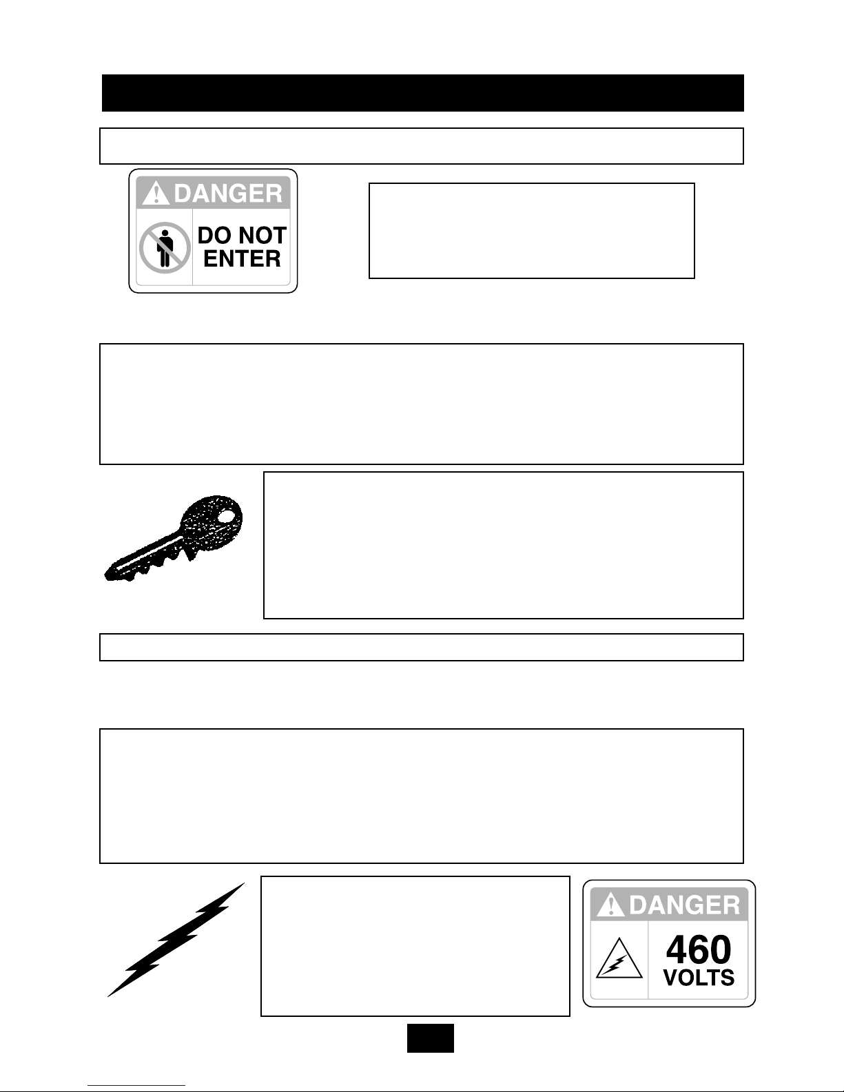
NEVER ENTER ANY PART OF THE BALER UNLESS THE DISCONNECT
SWITCH HAS BEEN TURNED OFF AND PADLOCKED. Before starting the
baler, be sure no one is inside. Be certain that everyone is clear of all points of
operation and pinch point areas before starting. See Lock-Out & Tag-Out
instructions in the Maintenance section.
THE EMPLOYER SHOULD ALLOW ONLY AUTHORIZED AND TRAINED PERSONNEL TO OPERATE
THIS BALER. This baler is equipped with a key oper-
ated locking system. The key(s) should be in the possession of only authorized personnel. Turn off and
remove key after use.
Pay close attention to the RED WARNING LIGHT on the control panel. If the light
is illuminated when the feed gate is raised, there is a malfunction of the magnetic interlock system. IN THIS EVENT, DISCONTINUE USE OF THE BALER AND
LOCK-OUT & TAG-OUT THE BALER PER THE INSTRUCTIONS IN THE
MAINTENANCE SECTION, PAGE 2-1. Perform necessary repairs before continuing operation of the baler.
ONLY AUTHORIZED PERSONNEL
SHOULD BE ALLOWED INSIDE THE
PANEL BOX. The panel box contains
high voltage components. See Lock-Out
& Tag-Out instructions in the
Maintenance section.
BE CERTAIN TURNBUCKLE AND LATCH IS FULLY LOCKED IN PLACE ON BALE
CHAMBER DOOR BEFORE STARTING BALER.
STAND CLEAR WHILE
BALER IS IN OPERATION.
WARNING: DO NOT OPERATE BALER UNTIL OPERATING INSTRUCTIONS ARE
THOROUGHLY UNDERSTOOD.
1-2
Federal regulation prohibits operation by persons under 18 years of age.
Page 6
1 OPERATION
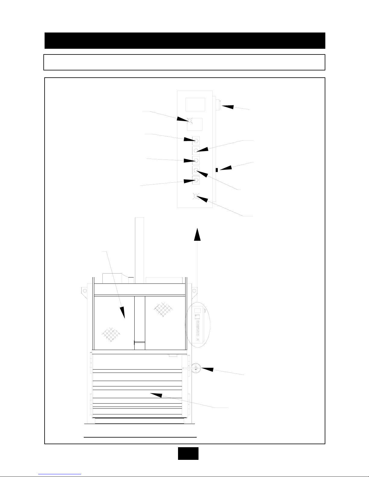
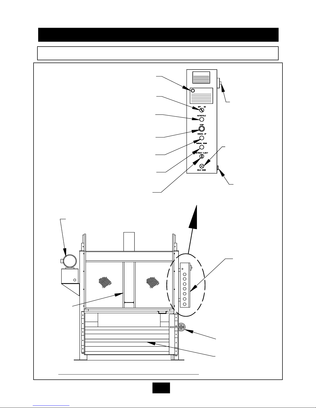
CONTROLS FOR V-4830HD, V-6030HD, V-6030LP, & V-7230HD
FRONT VIEW - VERTICAL BALER
MANUAL DOWN PUSHBUTTON
BALE MADE LIGHT
RED WARNING LIGHT
AUTOCYCLE BUTTON
KEYED ON-OFF SWITCH
EMERGENCY STOP BUTTON
MANUAL UP PUSHBUTTON
MOTOR OVERLOAD
RESET BUTTON
(ON DOOR)
DISCONNECT SWITCH
FEED GATE
CONTROL PANEL
PANEL BOX
TURNBUCKLE TO BALE
CHAMBER DOOR LATCH
BALE CHAMBER DOOR
WARNING
NOTICE
1-3
Page 7
1 OPERATION
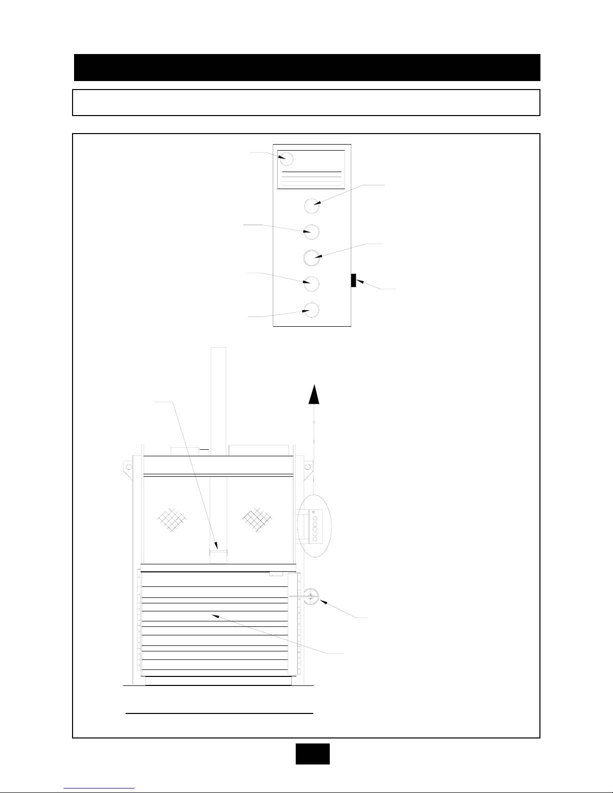
CONTROLS FOR V-6030 & V-4830
WARNING
STOP
MANUAL DOWN
MANUAL UP
AUTO CYCLE
OFF ON
RED WARNING LIGHT
KEYED ON-OFF SWITCH
AUTOCYCLE BUTTON
EMERGENCY STOP
BUTTON
MOTOR OVERLOAD
RESET BUTTON
(ON DOOR)
MANUAL UP BUTTON
MANUAL DOWN BUTTON
FEED GATE
TURNBUCKLE TO BALE
CHAMBER DOOR LATCH
BALE CHAMBER DOOR
CONTROL PANEL
PANEL BOX
NOTE: A fused disconnect is not provided on these models. The disconnect
must be provided, by the installer, per
the installation instructions in the
Installation section of this manual.
FRONT VIEW - VERTICAL BALER
1-4
Page 8
1 OPERATION
CONTROLS FOR V-6042LP
1-5
FRONT VIEW - LOW PROFILE VER
TICAL BALER
RETRACT/EJECT SWITCH
SIDE-MOUNTED
POWER UNIT
MANUAL DOWN PUSHBUTTON
BALE MADE LIGHT
RED WARNING LIGHT
AUTOCYCLE BUTTON
KEYED ON-OFF SWITCH
EMERGENCY STOP BUTTON
MANUAL UP PUSHBUTTON
RESET BUTTON
(ON DOOR)
DISCONNECT
SWITCH
FEED GATE
CONTROL PANEL
PANEL BOX
TURNBUCKLE TO BALE
CHAMBER DOOR LATCH
BALE CHAMBER DOOR
Page 9

ON-OFF (Keyed Selector Switch)
Turning this switch to the ON position activates the other controls on the control station.
The baler can not be operated unless the key is in the switch and the switch is in the ON
position. The purpose of this switch is to allow only authorized and trained personnel to
operate the baler. The key should be removed from the baler when not in use and should
stay in the possession of only responsible and trained personnel.
EMERGENCY STOP (Red Mushroom Head Pushbutton)
Depressing this button will stop the machine at any point in the cycle.
AUTOCYCLE (Green Pushbutton)
The AUTOCYCLE button can be used only when the feed gate and bale door are closed
and the keyswitch is in the ON position. Once depressed, the AUTOCYCLE button will
cause the platen to move to the fully down position and back to the fully raised position
(one complete cycle).
MANUAL UP (Black Pushbutton)
This button will only start the baler with the keyswitch in the ON position. Depressing the
button will raise the platen with the feed gate and bale door opened or closed. It is normally
used during bale ejection. It can also be used to interrupt the automatic cycle and raise the
platen should it become necessary. The MANUAL UP button is a “Hold To Run” control,
causing the baler to stop when it is released. WARNING: STAY CLEAR OF MOVING
PARTS WHEN USING THE MANUAL UP BUTTON WITH THE FEED GATE OPEN.
MANUAL DOWN (Black Pushbutton)
This button will only start the baler with the keyswitch in the ON position. Depressing the
button will lower the platen only if the feed gate and bale door are closed. It can be used to
interrupt the automatic cycle and lower the platen should it become necessary. The MANUAL DOWN button is a “Hold To Run” control, causing the baler to stop when it is released.
RED WARNING LIGHT
This light will warn the operator of a magnetic interlock switch malfunction. If the light is on
and the feed gate is in the up position, there is a problem. Discontinue use of the baler.
Turn off the baler and Lock-out and Tag-out per the instructions on page 2-1. Then call a
qualified service person. The light SHOULD BE ON when the feed gate is in the down position.
BALE MADE LIGHT (Not included on V-6030 and V-4830 models)
This light will come on if enough material has been compacted to make a complete bale.
RETRACT/EJECT (Spring-centered Switch) (USED ON THE V-6042LP ONL
Y)
This spring-centered switch will eject the bale by means of a hydraulic ejector when the
switch is held to the EJECT position. When the button is held to the RETRACT position, the
ejector will retract. The MANUAL UP button must be depressed and held at the same time
the RETRACT/EJECT switch is used.
1 OPERATION
CONTROL DESCRIPTION
1.
2.
3.
4.
5.
6.
7.
8.
1-6
Page 10
1 OPERATION
T
O MAKE A BALE : HD & LP Units
1. Feed material into baler. If starting a new bale, place a large flat piece of mater-
ial flat on the baler floor. NOTE: Do not attempt to overfill the feed chamber by
forcing material into the chamber with the feed gate. This can cause gate release
malfunction and may damage baler.
2. Pull gate handle down to close feed gate. NOTE: Check red warning light
before closing feed gate. If gate is open and light is on, discontinue use of the
baler and call for service.
3. To start the baler, insert the key into the keyswitch and turn to the ON
position.
4. Press the AUTOCYCLE button. The platen will make a complete cycle down
and back up. When the platen is in the full up position, the feed gate will automatically open and the motor will automatically shutdown.
5. Repeat steps 1 through 4 until platen stops in down position and “BALE MADE”
light comes on.
NOTE: In normal operation, the feed gate will be open when you walk up to
place material into the baler. For added security, the feed gate can be manually
closed after the AUTOCYCLE(S). To open the gate, you will have to insert the
key into the keyswitch and run the baler through a complete AUTOCYCLE.
IN CASE OF EMERGENCY:
Push the large red button to
STOP
OPERATING INSTRUCTIONS - MAKING A BALE
WARNING: DO NOT OPERATE BALER UNTIL OPERATING INSTRUCTIONS ARE
UNDERSTOOD.
See pages 1-3 through 1-5 for control panel layout and location.
1-7
WARNING: Interlocks and safety devices were installed on this unit for
your protection. Never disable or bypass any interlock or safety
device. Failure to comply with this warning could result in serious injury or
death.
Page 11
TO MAKE A BALE : V-6030 & V-4830
1. Feed material into baler. If starting a new bale, place a large flat piece of mater-
ial flat on the baler floor. NOTE: Do not attempt to overfill the feed chamber by
forcing material into the chamber with the feed gate. This can cause gate release
malfunction and may damage baler.
2. Pull gate handle down to close feed gate. NOTE: Check red warning light
before closing feed gate. If gate is open and light is on, discontinue use of the
baler and call for service.
3. To start the baler, insert the key into the keyswitch and turn to the ON
position.
4. Press the AUTOCYCLE button. The platen will make a complete cycle down
and back up. When the platen is in the full up position, the feed gate will automatically open and the motor will automatically shutdown.
5. Repeat steps 1 through 4 until the arrow on the platen dwells in direct line with
the arrow on the NOTICE decal on the feed gate, before returning to the up
position.
NOTE: In normal operation, the feed gate will be open when you walk up to
place material into the baler. For added security, the feed gate can be manually
closed after the AUTOCYCLE(S). To open the gate, you will have to insert the
key into the keyswitch and run the baler through a complete AUTOCYCLE.
WARNING: Interlocks and safety devices were installed on this unit for
your protection. Never disable or bypass any interlock or safety
device. Failure to comply with this warning could result in serious injury or
death.
IN CASE OF EMERGENCY:
Push the large red button to
STOP
OPERATING INSTRUCTIONS - MAKING A BALE
1 OPERATION
1-8
WARNING: DO NOT OPERATE BALER UNTIL OPERATING INSTRUCTIONS ARE
UNDERSTOOD.
See pages 1-3 through 1-5 for control panel layout and location.
Page 12

When the BALE MADE light comes on, it is time to tie off the bale and eject the bale
from the baler. See page 1-3 for control panel layout and location. See the following
page for a diagram of the following steps.
FOR BALE TIE OFF & BALE EJECT (HD MODELS):
1. Depress the MANUAL UP button until the feed gate opens.
2. Insert a large, flat piece of material across the top of the bale.
3. Close feed gate and depress the AUTOCYCLE button. The platen
will stop in the down position and the BALE MADE light will be illuminated.
CAUTION: CLEAR ALL PERSONNEL FROM FRONT OF BALER
BEFORE PROCEEDING WITH STEPS 4 THROUGH 8.
4. Release the bale chamber door latch on the side of baler and open
the bale chamber door all the way. Feed gate is closed but will raise
when the chamber door is opened.
5. CAUTION: Wear safety glasses and leather gloves during the following operation:
Tie off bale by inserting bale ties through the platen, “loop end” first.
Always insert bale ties through the tie slots in the platen, first.
Feed wire through until it comes out of the slot in the baler floor.
Tie off each tie. Bale ties should be tightened only hand tight, allowing for bale expansion when released.
6. Standing at the side, make sure all personnel are clear of the front of
the baler. Depress the MANUAL UP button.
7. Hold the MANUAL UP button until bale ejects, then release the
button.
8. Remove bale.
9. Close and latch the bale chamber door. Close feed gate. Depress
AUTOCYCLE to cycle and reset ejector. Bale sequence is ready to
be repeated.
1 OPERATION
OPERATING INSTRUCTIONS BALE TIE OFF/BALE EJECT FOR V-6030HD, V-4830HD, V-7230HD
1-9
Page 13
1 OPERATION
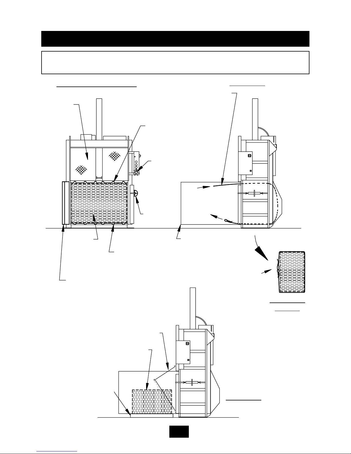
DIAGRAM BALE TIE OFF/BALE EJECT FOR V-6030HD, V-4830HD, V-7230HD
GATE CLOSED.
STEP 3.
PLATEN - BALE TIE
GUIDE, 6 PLACES.
SEE STEP 5.
BALE
MADE
LIGHT
DOOR
LATCH OPEN
BALE CHAMBER DOOR - OPEN.
SEE STEP 4.
FLOOR - BALE TIE
GUIDE, 6 PLACES.
SEE STEP 5.
FEED
FRONT VIEW OF BALER
SIDE VIEW
BALE TIE - TIGHTENED
HAND TIGHT
BALE DURING EJECTION
BALE
PALLET RECOMMENDED
FOR SUPPORTING BALE
SIDE VIEW
BALE CHAMBER
DOOR
SIDE VIEW
- BALE
BALE TIE - INSERT AND PUSH THROUGH
PLATEN GUIDES. TIES WILL CIRCLE THE
BALE AND COME OUT OF THE FLOOR
GUIDES. SEE STEP 5.
BALE
1-10
Page 14

When the BALE MADE light comes on, it is time to tie off the bale and eject the bale
from the baler. See page 1-3 for control panel layout and location. See the following
page for a diagram of the following steps.
FOR BALE TIE OFF & BALE EJECT (V-6030LP):
1. Depress the MANUAL UP button until the feed gate opens.
2. Insert a large, flat piece of material across the top of the bale.
3. Close feed gate and depress the AUTOCYCLE button. The platen
will stop in the down position and the BALE MADE light will be illuminated.
CAUTION: CLEAR ALL PERSONNEL FROM FRONT OF BALER
BEFORE PROCEEDING WITH STEPS 4 THROUGH 8.
4. Release the bale chamber door latch on the side of baler and open
the bale chamber door all the way. Feed gate is closed but will raise
when the chamber door is opened.
5. CAUTION: Wear safety glasses and leather gloves during the following operation:
Facing the front of the bale, tie off bale by inserting bale ties (loop
end first) through the platen. Always insert bale ties through the
tie slots in the platen, first. Go to the rear of the baler and feed
the loop end of the bale ties down and through the aligned tie slots in
the floor. Finally, go to the front of the baler and tie each of the
ties. Bale ties should be tightened only hand tight, allowing for bale
expansion when released.
6. Before ejecting the bale, go to the rear of the baler and manually
engage the bale eject latch (WARNING: Never engage eject latch if
bale door is closed). To engage the latch, pull (rotate) the latch handle up all the way. Standing at the side, make sure all personnel are
clear of the front of the baler. Depress the MANUAL UP button.
7. Hold the MANUAL UP button until bale ejects, then release button.
8. Remove bale.
9. Close and latch bale chamber door. Close feed gate. Depress AUTOCYCLE to cycle and reset ejector. Bale sequence is ready to be
repeated.
1 OPERATION
OPERATING INSTRUCTIONS BALE TIE OFF/BALE EJECT FOR V-6030LP
1-11
Page 15
1 OPERATION
DIAGRAM - BALE TIE OFF/BALE EJECT FOR V-6030LP
FEED
GATE
PLATEN - BALE TIE
GUIDE, 6 PLACES.
SEE STEP 5.
BALE
MADE
LIGHT
DOOR
LATCH OPEN
BALE CHAMBER DOOR OPEN.
SEE STEP 4.
FLOOR - BALE TIE
GUIDE, 6 PLACES.
SEE STEP 5.
FRONT VIEW OF BALER
SIDE VIEW
BALE TIE - TIGHTENED
BALE DURING EJECTION
- STEP 7.
BALE
PALLET RECOMMENDED FOR
SUPPORTING
BALE
SIDE VIEW
BALE CHAMBER
DOOR
SIDE VIEW -
BALE
BALE TIE - INSERT AND PUSH
THROUGH PLATEN GUIDE.
SEE STEP 5.
BALE
- CLOSED.
STEP 3.
HAND TIGHT
BALE EJECT LATCHENGAGED. STEP 6.
FEED TIES
THROUGH
FLOOR
GUIDES STEP 5.
1-12
Page 16

1 OPERATION
OPERATING INSTRUCTIONS BALE TIE OFF/BALE EJECT FOR V-6042LP
1-13
When the BALE MADE light comes on, it is time to tie off the bale and eject the bale
from the baler. See page 1-5 for control panel layout and location. See the following
page for a diagram of the following steps.
FOR BALE TIE OFF & BALE EJECT (V-6042LP):
1. Depress the MANUAL UP button until the feed gate opens.
2. Insert a large, flat piece of material across the top of the bale.
3. Close feed gate and depress the AUTOCYCLE button. The platen
will stop in the down position and the BALE MADE light will be illuminated.
CAUTION: CLEAR ALL PERSONNEL FROM FRONT OF BALER
BEFORE PROCEEDING WITH STEPS 4 THROUGH 8.
4. Release the bale chamber door latch on the side of baler and open
the bale chamber door all the way. Feed gate is closed but will raise
when chamber door is opened.
5.
CAUTION:
Wear safety glasses and leather gloves during the follow-
ing operation: Tie off bale by inserting bale ties through the platen,
“loop end” first. Always insert bale ties through the tie slots in the
platen, first. Feed wire through until it comes out of the slot in the
baler floor. Tie off each tie. Bale ties should be tightened only hand
tight, allowing for bale expansion when platen is released.
6. Depress the MANUAL UP button until the platen reaches its up position.
7. Standing at the side, make sure all personnel are clear of the front of
the baler. Depress and hold the MANUAL UP button and hold the
RETRACT/EJECT switch to the right (EJECT) until the bale ejects.
Depress and hold the MANUAL UP button and hold the RETRACT/
EJECT switch to the left (RETRACT) until the ejector retracts all the
way. Baler will not function if ejector is not fully retracted.
8. Remove bale from in front of baler.
9. Close and latch the bale chamber door. Bale sequence is ready to be
repeated.
NOTE: You can close the feed gate at this time if added security is required. To
open the gate you will have to run the baler through a complete AUTOCYCLE.
Page 17

1 OPERATION
DIAGRAM - BALE TIE OFF/BALE EJECT FOR V-6042LP
1-14
FEED GATE CLOSED.
STEP 3.
PLATEN - BALE TIE
SLOT, 6 PLACES.
SEE STEP 5.
BALE
MADE
LIGHT
DOOR
LATCH OPEN
BALE CHAMBER DOOR - OPEN.
SEE STEP 4.
FLOOR - BALE TIE
SLOT, 6 PLACES.
SEE STEP 5.
FRONT VIEW OF BALER
SIDE VIEW
BALE TIE - TIGHTENED
HAND TIGHT
BALE DURING EJECTION
SEE STEP 7
RECOMMEND
SUPPORTING
BALE WITH
PALLET JACK
OR FORK LIFT
SIDE VIEW
BALE
CHAMBER
DOOR
SIDE VIEW
- BALE
BALE TIE - INSERT AND PUSH
THROUGH PLATEN TIE SLOTS.
TIES WILL COME OUT OF THE
FLOOR TIE SLOTS. SEE STEP 5.
BALE
Page 18

1 OPERATION
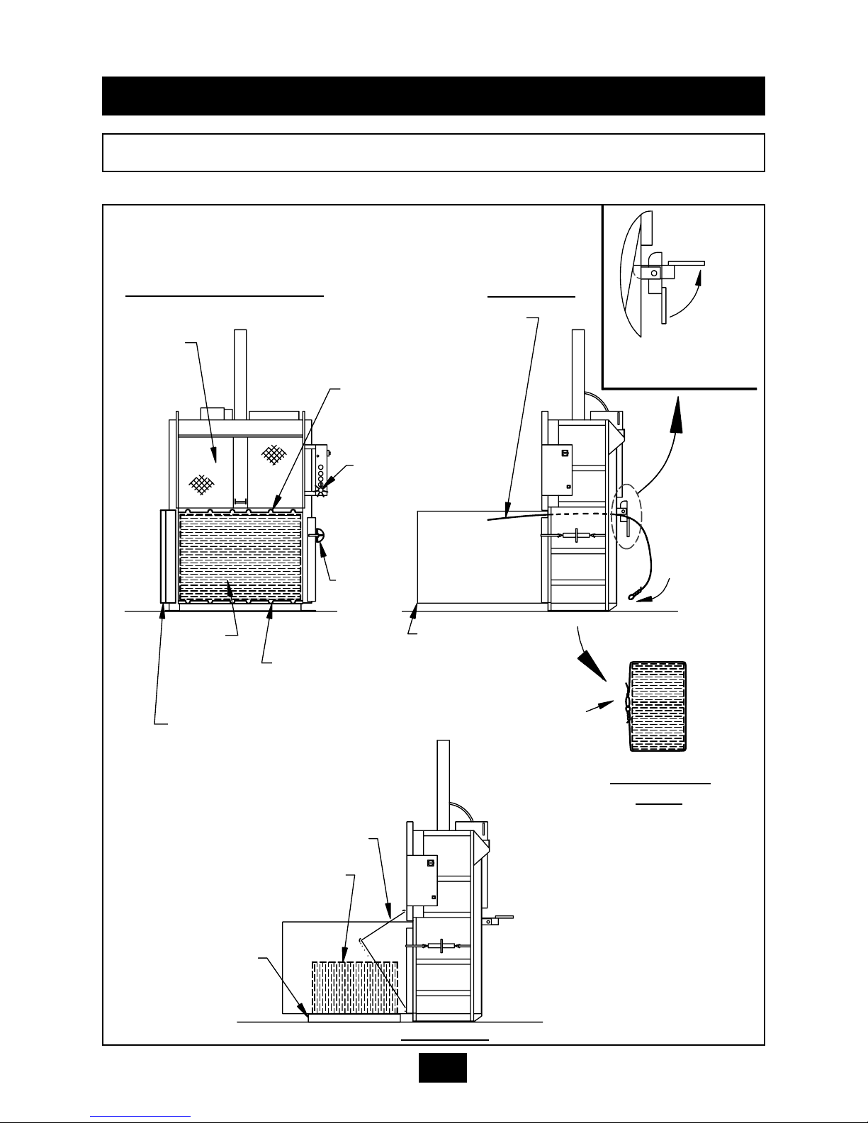
OPERATING INSTRUCTIONS BALE TIE OFF/BALE EJECT FOR V-4830 & V-6030
When the arrow decal on the platen dwells in direct line with the notice decal arrow on
the feed gate, it is time to tie off the bale and eject the bale from the baler. See page
1-4 for control panel layout and location. See the following page for a diagram of the following steps.
FOR BALE TIE OFF & BALE EJECT (V-4830 & V-6030):
1. Insert a large, flat piece of material across the top of the bale.
2. Close feed gate and depress the MANUAL DOWN button. The platen
will dwell in the down position and the arrows on the platen and feed
gate will be in direct line. Release the MANUAL DOWN button.
3. Place the ejector hook on the platen (located on the rear of machine).
CAUTION: CLEAR ALL PERSONNEL FROM FRONT OF BALER
BEFORE PROCEEDING WITH STEPS 4 THROUGH 7.
4. Release the bale chamber door latch on the side of baler and open the
bale chamber door all the way. Feed gate is closed but will raise when
chamber door is opened.
5. CAUTION: Wear safety glasses and leather gloves during the follow-
ing operation: Tie off bale by inserting bale ties through the platen,
“loop end” first. Always insert bale ties through the tie slots in the
platen, first. Feed wire through until it comes out of the slot in the
back of baler. Go to the rear of the baler and feed the looped end of
the bale ties down and through the aligned tie slots in the floor.
Finally, go to the front of the baler and tie each of the ties. Bale ties
should be tightened only hand tight, allowing for bale expansion
when platen is released.
6. Standing at the side, make sure all personnel are clear of the front of
the baler. Depress and hold the MANUAL UP button until the bale
ejects.
7. Remove bale from in front of baler. Close and latch the bale door.
8. Close the feed gate, and press the MANUAL DOWN button until the
ejector hook releases from the platen
10. Press and hold the MANUAL UP button until the platen is in the up
position, and the feed gate raises. Bale sequence is ready to be
repeated.
NOTE: You can close the feed gate at this time if added security is required. To
open the gate you will have to run the baler through a complete AUTOCYCLE.
1-15
Page 19

DIAGRAM - BALE TIE OFF/BALE EJECT FOR V-4830 & V-6030
1 OPERATION
FRONT VIEW
SIDE VIEW
WIRE GUIDES
ARROWS ALIGNED
TO SHOW BALE
MADE POSITION
EJECTOR HOOK ON
PLATEN
INSERT WIRE TIES
THROUGH FLOOR
GUIDES
PALLET RECOMMENDED
HOOK POSITION WHILE
BALING
BALE DOOR
BALE DOOR LATCH
FEED GATE
BALE TIE- INSERT AND PUSH
THROUGH PLATEN AND FLOOR
GUIDES. TIE BALE TIES HAND
TIGHT TO ALLOW FOR EXPANSION.
BALE- AFTER
EJECTION
BALE- DURING
EJECTION
EJECTOR
HOOK WHEN
BALE IS
EJECTED
1-16
Page 20

1 OPERATION
DIAGRAM - TIE SLOT CLEANING
1-17
AT TIMES THE TIE SLOTS MAY BECOME OBSTRUCTED WITH MATERIAL AND PREVENT THE
WIRE TIES FROM PROPER INSERTION THROUGH THE SLOTS AND AROUND THE BALE. THE
BALER IS SUPPLIED WITH A SLOT CLEANING TOOL FOR RODDING OUT THE TIE SLOTS.
TO USE, INSERT THE TOOL INTO THE PROBLEM SLOT AND PUNCH OR DRAG THE MATERIAL
OUT.
IF THE WIRE GUIDES BECOME OBSTRUCTED WITH MATERIAL , THE BALER SHOULD BE
EMPTIED, LOCKED OUT AND TAGGED OUT, AND THE PLATEN SHOULD BE CHOCKED AS
SHOWN IN THE MAINTENANCE SECTION OF THIS MANUAL BEFORE CLEANING THE WIRE
GUIDES.
FRONT VIEW
SIDE VIEW
BALE
WARNING LIGHT
FEED GATE
WIRE GUIDES
TIE SLOTS
SLOT CLEANING T
OOL
HANDLE
Page 21

WARNING DECAL REQUIREMENTS
When your baler leaves the factory, several WARNING DECALS are installed for protection. These labels are subject to wear and abuse due to the nature of the operation.
THESE DECALS MUST BE MAINTAINED. Additional decals may be purchased
through your distributor.
1 OPERATION
DECALS
DANGER: DO NOT ENTER.
DANGER: 208 VOLTS. or
DANGER: 230 VOLTS. or
DANGER: 460 VOLTS.
DANGER: 208 VOLTS. or
DANGER: 230 VOLTS. or
DANGER: 460 VOLTS.
CAUTION: GATE MUST BE CLOSED BEFORE OPERATING
BALER.
DANGER: KEEP HANDS OUT.
CAUTION: STAND CLEAR WHEN BALE IS EJECTED.
CAUTION: STAND CLEAR WHILE OPERATING DOOR
LOCK.
NOTICE: PERIODIC MAINTENANCE IS REQUIRED AND IS
YOUR RESPONSIBILITY.
DANGER. DISCONNECT AND LOCK OUT POWER
BEFORE OPENING THIS PANEL.
WARNING: FEDERAL REGULATION PROHIBITS OPERA-
TION OF THIS EQUIPMENT BY PERSONS UNDER 18
YEARS OF AGE.
MARATHON EQUIPMENT COMPANY.
Decal Number 06-0039 Decal Number 06-0043 Decal Number 06-0044 Decal Number 06-0045 Decal Number 06-0101 Decal Number 06-0102 Decal Number 06-0103 Decal Number 06-0115 -
Decal Number 06-0116 Decal Number 06-0117 Decal Number 06-0118 -
Decal Number 06-0119 -
Decal Number 06-0120 -
Decal Number 06-0121 -
Decal Number 06-0126 -
1-18
Page 22

WARNING DECAL REQUIREMENTS
When your baler leaves the factory, several WARNING DECALS are installed for protection. These labels are subject to wear and abuse due to the nature of the operation.
THESE DECALS MUST BE MAINTAINED. Additional decals may be purchased
through your distributor.
1 OPERATION
DECALS
CAUTION: DO NOT OPERATE BALER UNTIL OPERATING
INSTRUCTIONS ARE UNDERSTOOD. NEVER PLACE ANY
PART OF BODY INSIDE BALE CHAMBER. STAND CLEAR
WHILE BALER IS IN OPERATION. FEDERAL LAW PROHIBITS OPERATION OF THIS EQUIPMENT BY PERSONS
UNDER 18 YEARS OF AGE. TURN OFF AND REMOVE KEY
AFTER USE. STAND CLEAR WHILE EJECTING BALE.
(Also, includes Operating Instructions).
WARNING: STAY CLEAR OF BALE CHAMBER WHEN
LIGHT IS ILLUMINATED. IF LIGHT IS ILLUMINATED WHEN
BALE DOOR OR FEED GATE IS OPEN, DISCONTINUE
USE OF THIS EQUIPMENT AND CALL QUALIFIED SERVICE PERSONNEL.
DANGER: STAY OFF TOP BALER. DO NOT CLIMB ON
SIDES. USE WORK PLATFORM FOR SERVICING.
NOTICE BALE MADE IF ARROW DOES NOT PASS.
(V-4830 & V-6030 ONLY)
ORANGE ARROW.
(V-4830 & V-6030 ONLY)
Decal Number 06-0130 -
Decal Number 06-0132 -
Decal Number 06-0133 -
Decal Number 06-0651-
Decal Number 06-0652 -
1-19
Page 23

1 OPERATION
DECAL PLACEMENT FOR HD & LP MODELS
06-0116
06-0103
06-0039
DISCONNECT
06-0132
06-0117
06-0130
06-0119
06-0120
06-0043
06-0133
06-0118
06-0121
06-0126
06-0115
06-0102 or
06-0101 or
06-0044
06-0045
FRONT
VIEW
SIDE VIEW
1-20
FRONT VIEW OF V-6042LP
06-0101, 06-0102, OR 06-0103 (ON SIDE-MOUNTED POWER UNIT)
ALL OTHER DECALS ON THE
V-6042LP ARE LOCATED AS
SHOWN ABOVE.
NOTE: Installation is not
complete until all decals are
in place.
Page 24

1 OPERATION
DECAL PLACEMENT FOR V-4830 & V-6030
U
L
R
U
L
LISTED
16BF
C
DOVER
VERNON, AL − YERINGTON, NV − CLEARFIELD, PA
1−800−633−8974
VERTICAL BALER
PATENT # 5,044,271
MODEL
SERIAL #
THIS PRODUCT COMPLIES WITH
ANSI Z245.5−1990.
R
R
FRONT VIEW
OF PLATEN
06-0101,
OR 06-0102,
OR 06-0103
06-0652
06-0132
06-0119
PLACE ON
PANEL BOX
BRACKET
06-0121
06-0118
06-0275
FRONT VIEW
SIDE VIEW
06-0120
06-0101,
OR 06-0102,
OR 06-0103
06-0130
06-0133
BOTH SIDES
06-0117
06-0097
06-0039
06-0651
06-0116
06-0115
06-0126
06-0147
NOTE: Installation is not
complete until all decals are
in place.
1-21
Page 25

2 MAINTENANCE
LOCK-OUT & TAG-OUT INSTRUCTIONS
ELECTRICAL: The panel box contains high voltage
components. Only authorized service personnel
should be allowed inside the box. Authorized service
personnel should be allowed inside the box only
after the baler has been locked-out and tagged-out.
FOREWORD: Before entering any part of the baler, be
sure that all sources of energy have been shut off, all
potential hazards have been eliminated, and the baler
is locked-out and tagged-out in accordance with
OSHA and ANSI requirements. Before servicing the
hydraulic system or the inside of the bale chamber,
THE PLATEN MUST BE PROPERLY SUPPORTED AS
SHOWN ON THE NEXT PAGE.
The specific lock-out and
tag-out instructions may vary from company to company (i.e.
multiple locks may be required, or other machinery may need to
be locked-out and tagged-out). The following instructions are
provided as minimum guidelines.
INSTRUCTIONS
1. Move the main disconnect lever to the OFF position. The disconnect switch on
models V-4830 & V-6030 is located in the disconnect panel on the wall. The disconnect
switch on all other models is located in the panel box of the machine.
2. Padlock the disconnect lever with a keyed padlock and take the key with
you.
(To insert the lock through the lock tab on the disconnect handle, pull the lock tab out of
the disconnect handle when the handle is in the OFF position.)
3. Along with the padlock, place an appropriate, highly visible, warning tag on
the disconnect lever. The tag should provide a warning such as: “ Danger: Do not oper-
ate equipment. Person working on equipment.” or “ Warning: Do not energize without the permission of ________________________.”
4. After locking and tagging the baler, try to start and operate the baler (as outlined in the Operating Instructions) to make sure the lock-out and tag-out is
effective. If the lock-out and tag-out is effective, remove the key from the
keyswitch and take it with you.
HYDRAULIC: Stored hydraulic energy must be removed from the baler hydraulic cir-
cuit for complete lock-out and tag-out. Make sure that this energy has been relieved
by manually depressing the solenoid valve pin located in the center of the coil end of
each valve.
2-1
(Typical disconnect shown, other types may lock-out differently.)
Page 26

2 MAINTENANCE
SUPPORTING OF PLATEN
BALE CHAMBER DOOR,
OPEN
FEED GATE OPEN PLATEN IN UP
POSITION
DISCONNECT
IN OFF POSITION AND
LOCKED-OUT
4” X 4” WOOD
BEAM IN EACH
REAR CORNER
FRONT VIEW OF BALER
WARNING: BEFORE ENTERING BALE CHAMBER FOR SERVICE, BE SURE THAT
THE PLATEN IS SECURELY SUPPORTED. AT A MINIMUM, USE TWO WOODEN
4” X 4” BEAMS (GOOD CONDITION), CUT TO FIT SNUG IN EACH REAR CORNER
OF THE CHAMBER WHILE SUPPORTING THE PLATEN IN THE UP POSITION. THE
TOP END OF EACH BEAM SHOULD BE IN THE EXTREME CORNER, WHILE THE
BOTTOM END SHOULD BE POSITIONED OVER THE OUTER TIE SLOT IN THE
FLOOR. SEE DIAGRAM BELOW.
DANGER: DO NOT CLIMB ON SIDES OF BALER. USE A LADDER OR WORK
PLATFORM WHEN WORKING ON TOP OF THE BALER OR OTHER AREAS OF THE
BALER THAT CAN NOT BE REACHED FROM GROUND LEVEL.
WARNING: PARTS OF THE PLATEN WILL EXTEND ABOVE THE TOP OF THE
BALER WHEN THE PLATEN IS FULLY RAISED.
BEAM OVER
OUTER TIE
SLOT IN FLOOR
2-2
Page 27

Check external hoses for chafing, rubbing, leakage, or other deterioration and damage. Tighten all fittings as necessary. Check hydraulic cylinder, cylinder pin and
bolts for signs of wear and fatigue.
Check for any obvious unsafe conditions, such as operator obstructions, in baler
area.
Check oil level in hydraulic reservoir.
Lubricate the door hinge, and mechanical door lock with oil.
Check magnetic interlock on feed gate for proper operation.
Clean out wire guides on machines equipped with them. Follow platen chocking
procedures and lock out and tag out procedures.
Check guide shoes for wear, and lubricate as needed with an all purpose grease.
Apply a light coating of all purpose grease in the feed gate tracks.
Apply a light application of all purpose oil to the feed gate latch moving parts.
Check functional operation of controls and options (stop button, timers, lights, etc.).
Check hydraulic cylinder, and hoses, for leakage, chafing and wear.
The hydraulic filter should be cleaned at regular annual intervals.
The filter may be removed from the power unit through the cleanout cover in the top
of the reservoir.
Care should be exercised in cleaning the fiIter to insure that the element is not torn.
Clean the element with a soft brush and standard industrial solvent.
Replace the filter after cleaning and check fittings for tightness. Pump noise and a
"crackle" sound is most often caused by air entering the pump suction line.
Tightening the suction fittings will usually eliminate the problem.
2 MAINTENANCE
PERIODIC MAINTENANCE
1.
2.
3.
4.
5.
6.
7.
8.
9.
1.
2.
1.
2.
3.
4.
MONTHLY
THREE MONTHS
ANNUAL FILTER MAINTENANCE
ANNUALLY
1.
2.
3.
Replace the hydraulic fluid. See Recommended Oil.
Electric motor bearings should be lubricated once a year.
Clean the top of the power unit to remove the dirt build up.
2-3
WARNING: BEFORE PERFORMING ANY MAINTENANCE OR SERVICE PROCEDURES ON THE
BALER, MAKE SURE THE BALER IS LOCKED-OUT AND TAGGED OUT PER THE INSTRUCTIONS
ON PAGE 2-1. FOR MAINTENANCE INSIDE THE BALE CHAMBER, SEE THE PLATEN CHOCKING
PROCEDURE ON PAGE 2-2.
Page 28

With the key switch in the ON position, use the MANUAL DOWN button to move the
platen to the full down position.
Turn off the power and perform the LOCK-OUT and TAG-OUT procedures
described on page 2-1.
Manually shift the solenoid valve in each direction to relieve pressure.
Remove the 1/4” plug from the 3/4” 90 degree elbow in the valve subplate.
Install a pressure gauge in the 1/4” hole.
Remove the Lock-out and Tag-out provisions and turn on power to the baler.
Have an operator hold the MANUAL DOWN button. This will start the baler and the
hydraulic system will build relief pressure. Turn the adjustment screw on the relief
valve clockwise to increase the pressure, or counter clockwise to decrease the
pressure. See CHARTS for proper setting for your model.
Tighten locknut on adjustment screw.
Have the operator release the MANUAL DOWN button and press the STOP button.
Turn off the power and perform the LOCK-OUT and TAG-OUT procedures
described on page 2-1.
Remove the pressure gauge and reinstall the 1/4” plug.
This procedure is complete.
1.
2.
3.
4.
5.
6.
7.
8.
9.
10.
11.
12.
2 MAINTENANCE
PROCEDURES - PRESSURE SETTING, INTERLOCK TESTING
HYDRAULIC SYSTEM PRESSURE SETTING
MAGNETIC INTERLOCK TESTING
1.
2.
3.
4.
This baler is equipped with a solid state output magnetic interlock switch. Because
it is a semiconductor device, it can not be checked with a continuity light or OHM
tester. The switch must be checked with the power ON. The RED WARNING
LIGHT on the control panel has been provided to indicate if the switch is working
properly.
To check the switch, turn the keyswitch to the ON position. When the feed gate or
bale door is open, the light should be off. When the bale door and feed gate are
closed, the light should be on.
If further verification is required, a volt meter (120V) may be connected to terminal
#2A and terminal #7 in the panel box. The meter should read “0” volts with the gate
open and 120 volts with the gate closed.
In no instance should the baler operate in either MANUAL DOWN or AUTOCYCLE
with the feed gate up or bale door open.
WARNING: IF THE INTERLOCK IS NOT WORKING PROPERLY, DISCONNECT
THE POWER AND LOCK-OUT AND TAG-OUT THE BALER UNTIL REPAIRS CAN
BE MADE.
DANGER: DO NOT CLIMB ON SIDES OF BALER. USE A LADDER OR WORK PLATFORM
WHEN WORKING ON TOP OF THE BALER OR OTHER AREAS OF THE BALER THAT CAN
NOT BE REACHED FROM GROUND LEVEL.
WARNING: PARTS OF THE PLATEN WILL EXTEND ABOVE THE TOP OF THE BALER
WHEN THE PLATEN IS FULLY RAISED.
2-4
Page 29

2 MAINTENANCE
PROCEDURES - CYLINDER REMOVAL
CYLINDER REMOVAL (ALL UNITS EXCEPT LOW PROFILE, LP)
Raise platen up to the top position with the MANUAL UP button.
Disconnect and Lock-out and Tag-out power per instructions on page 2-1.
Remove guide shoes.
Turn on power and lower platen using the MANUAL DOWN button. Turn off power.
Support platen with fork lift to take pressure off of cylinder pin and to prevent platen from falling
when pin is removed.
Remove bolts and cotter pins in cylinder pin.
Remove platen from front of baler.
Turn on power and retract cylinder rod.
Disconnect and Lock-out and Tag-out power.
Relieve hydraulic pressure by manually depressing solenoid valve (both sides).
Disconnect one hydraulic hose at a time. Plug the hose port before disconnecting the other hose.
NOTE: Remove hose fittings slowly.
WARNING: BE SURE HYDRAULIC CYLINDER IS SECURELY SUPPORTED BEFORE PROCEEDING.
With the hydraulic cylinder supported, loosen the 3/4” grade 5 cylinder bolts and grade 5 locknuts.
Remove cylinder.
Before reinstalling cylinder, check cylinder pin, bolts, and cylinder rod for signs of fatigue. Do not
reuse parts if wear or cracks are present.
To reinstall the cylinder, reverse the above steps.
Be sure to use new bolts, nuts, and cotter pins in the cylinder pin.
1.
2.
3.
4.
5.
6.
7.
8.
9.
10.
11.
12.
13.
14.
15.
16.
DANGER: DO NOT CLIMB ON SIDES OF BALER. USE A LADDER OR WORK PLATFORM WHEN
WORKING ON TOP OF THE BALER OR OTHER AREAS OF THE BALER THAT CAN NOT BE
REACHED FROM GROUND LEVEL.
WARNING: PARTS OF THE PLATEN WILL EXTEND ABOVE THE TOP OF THE BALER WHEN THE
PLATEN IS FULLY RAISED.
2-5
MAIN CYLINDER REMOVAL - LOW PROFILE
Raise platen up to the top position with MANUAL UP button. Lock-out and Tag-out power per
instructions on page 2-1. Remove guide shoes.
Turn on power and lower platen using MANUAL DOWN button. Turn off power.
Support platen with fork lift to take pressure off of cylinder pin and to prevent platen from falling
when pin is removed. NOTE: Because of the long pin length, make sure the fork lift is no closer
than 24” to the platen.
Remove the two bolts attaching the cylinder pin assembly to the front of the platen. The cylinder pin
assembly consists of a 21 3/4” long pin (1 1/2” dia) with a ”U” bracket welded to the end. This bracket fastens to the front of the platen with the two bolts. Slide the pin assembly out of the cylinder and
platen.
Remove platen from front of baler. Turn on power and retract cylinder rod.
Disconnect and Lock-out and Tag-out power. Relieve hydraulic pressure per Lock-out and Tag-out.
Disconnect one hydraulic hose at a time. Plug the hose port before disconnecting the other hose.
NOTE: Remove hose fittings slowly.
WARNING: SUPPORT HYDRAULIC CYLINDER BEFORE PROCEEDING.
With the hydraulic cylinder supported, remove the 1” grade 5 cylinder bolts and grade 5 locknuts.
Remove cylinder.
Before reinstalling cylinder, check cylinder pin, bolts, and cylinder rod for signs of fatigue. Do not
reuse parts if wear or cracks are present.
To reinstall the cylinder, reverse the above steps. Be sure to use new bolts, and cotter pins in the
cylinder pin.
1.
2.
3.
4.
5.
6.
7.
8.
9.
10.
11.
12.
Page 30

2 MAINTENANCE
PROCEDURES - CYLINDER REBUILDING, LIMIT SWITCH ADJUSTMENT
CYLINDER REBUILDING
Remove hydraulic cylinder from baler.
Remove bolts and retainer plate from gland.
Remove internal retaining ring.
Remove rod from cylinder barrel.
Remove piston locknut and piston from cylinder rod.
Replace all seals. Discard old seals and old piston locknut.
Replace gland on rod.
Install piston on cylinder rod using new locknut (included in seal kit).
NOTE: Do not reuse old locknut. Torque new locknut to 1000-1200 ft-lbs.
Install piston and rod assembly in cylinder barrel. Be careful not to damage seals.
Install gland in barrel. Install internal retaining ring.
Bolt retainer plate to gland. Reinstall cylinder in baler.
1.
2.
3.
4.
5.
6.
7.
8.
9.
10.
11.
WARRANTY AND SERVICE ON MOTORS
If the baler motor fails under warranty, have it checked by a qualified electrician or service person. If
there is no problem with fuses or wiring, the motor should be taken to the nearest authorized motor warranty shop. If you do not have a list of qualified shops, contact Marathon Equipment Co. The motor warranty shop will be able to inspect the motor and determine if it is factory defective. If the motor failed due
to defects in material or workmanship, contact the factory to determine if the motor will be replaced or
repaired. If motor failure was not due to defective material or workmanship, it will be repaired only if customer agrees to pay for expenses. Marathon Equipment Co. will not absorb cost for pickup and delivery
to service centers. Removal and reinstallation are covered in the standard warranty policy.
2-6
LIMIT SWITCH ADJUSTMENT (ALL HD UNITS)
The baler has only one limit switch. This switch controls the size of the bale and activates the BALE MADE light.
Make a mark on the inside of the bale chamber 39 3/4” from the baler floor (top of
corrugations).
Close the bale chamber door and feed gate and lower the platen until the line just
touches the top of the platen side panel.
Turn off and lock-out and tag-out the power. Adjust the BALE MADE limit switch arm
to the highest point on the actuator.
Remove the Lock-out and Tag-out provisions and turn on power.
1.
2.
3.
4.
LIMIT SWITCH ADJUSTMENT (ALL LP UNITS)
The baler has only one limit switch. This switch controls the size of the bale and activates the BALE MADE light.
Make a mark on the inside of the bale chamber 29 3/4” from the baler floor (top of
corrugations).
Close the bale chamber door and feed gate and lower the platen until the line just
touches the top of the platen side panel.
Turn off and lock-out and tag-out the power. Adjust the BALE MADE limit switch arm
to the highest point on the actuator.
Remove the Lock-out and Tag-out provisions and turn on power.
1.
2.
3.
4.
Page 31

2 MAINTENANCE
PROCEDURES - FEED GA TE LATCH ADJUSTMENT
BALE DOOR
FEED GATE
LATCH
SPRING
FEED GATE
STRIKER
TENSION
ADJUSTMENT
NUT
BOLTS
FOR
STRIKER
NOTE: Adjustment is made by tightening or loosning the TENSION ADJUSTMENT NUT with the
feed gate in the up position. Spring tension
should not exceed 5 lbs to prevent excessive
wear on the feed gate latch and striker.
NOTE: In the event of excessive wear, the feed gate latch
STRIKER is removable and replaceable. Striker may be
replaced by removing the two (2) striker bolts. Access to the
striker bolts can be achieved by removing the front cover
from the bale door
2-7
Page 32

2 MAINTENANCE
PRINCIPLES OF OPERATION
OPERATING CHARACTERISTICS FOR:
V-6030HD, V-4830HD, V-6030LP, AND V-7230HD
When the AUTOCYCLE button is depressed, a contact is made that energizes the motor starter
coil, starting the electric motor and at the same time energizing T1 timer coil, T2 timer coil, and
R1 relay coil. When R1 is energized, the hydraulic oil is directed by the directional control valve
from a signal to the solenoid that shifts the valve. The oil is directed to extend the cylinder and
lower the platen. When T2 times out, the contacts reverse. This de-energizes R1 which causes
the down solenoid to de-energize, and the up solenoid to energize. Oil is directed to the rod end
of the cylinder and the platen is raised. As the platen reaches the full up position, the baler feed
gate opens. Opening the feed gate causes the magnetic interlock contact to open which stops
power to the motor starter coil and shuts the baler down. If the feed gate fails to open, the T1
timer will time out and break power to the motor starter coil, shutting the baler down.
NOTE: The BALE MADE LIGHT will be illuminated if the T2 timer times out while the BALE
MADE limit switch is activated. When this happens, the motor will stop with the platen in the
down position.
2-8
OPERA
TING CHARACTERISTICS FOR:
V-6030, AND V-4830HD
When the AUTOCYCLE button is depressed, a contact is made that energizes the motor starter
coil, starting the electric motor and at the same time energizing T1 timer coil, T2 timer coil, and
R1 relay coil. When R1 is energized, the hydraulic oil is directed by the directional control valve
from a signal to the solenoid that shifts the valve. The oil is directed to extend the cylinder and
lower the platen. When T2 times out, the contacts reverse. This de-energizes R1 which causes
the down solenoid to de-energize, and the up solenoid to energize. Oil is directed to the rod end
of the cylinder and the platen is raised. As the platen reaches the full up position, the baler feed
gate opens. Opening the feed gate causes the magnetic interlock contact to open which stops
power to the motor starter coil and shuts the baler down. If the feed gate fails to open, the T1
timer will time out and break power to the motor starter coil, shutting the baler down.
NOTE: When the platen dwells in the down position with the arrow on the platen in line with the
arrow on the NOTICE decal on the feed gate, it is time to tie the bale. See Bale Tie Off instructions on page 1-15.
Page 33

2 MAINTENANCE
PRINCIPLES OF OPERATION
V-6042 XLP OPERATING CHARACTERISTICS
Feed Gate and Platen Operation
When the AUTOCYCLE button is depressed, a contact is made that energizes the motor starter
coil, starting the electric motor and at the same time energizing T1 timer coil, T2 timer coil, and
R1 relay coil. When R1 is energized, the hydraulic oil is directed by the directional control valve
from a signal to the SV1A solenoid that shifts the valve. The oil is directed to the base end of
the cylinder to extend the cylinder and lower the platen. When T2 times out, the contacts
reverse. This de-energizes R1 which causes the down solenoid to de-energize, and the up
solenoid (SV1B) to energize. Oil is directed to the rod end of the cylinder and the platen is
raised. As the platen reaches the full up position, the baler feed gate opens. Opening the feed
gate causes the magnetic interlock contact to open which stops power to the motor starter coil
and shuts the baler down. If the feed gate fails to open, the T1 timer will time out and break
power to the motor starter coil, shutting the baler down. NOTE: The BALE MADE LIGHT will be
illuminated if the T2 timer times out while the BALE MADE limit switch is activated. When this
happens, the motor will stop with the platen in the down position.
Ejector Operation
When the bale is ejected, the MANUAL UP button must be depressed and held which energizes the motor starter coil, starting the electric motor. At the same time, the RETRACT/EJECT
switch must be turned and held to the right (EJECT). This energizes the coil on the SV2A solenoid valve causing it to shift and direct fluid to the base end of the cylinder which cause the
ejector to eject the bale.
When the ejector is retracted, the MANUAL UP button must be depressed and held which energizes the motor starter coil, starting the electric motor. At the same time, the RETRACT/EJECT
switch must be turned and held to the left (RETRACT). This energizes the coil on the SV2B
solenoid valve causing it to shift and direct fluid to the rod end of the cylinder which cause the
ejector to retract.
2-9
Page 34

2 MAINTENANCE
BALER SPECIFICATIONS
V-4830 V-6030 V-4830HD V-6030HD V-7230HD V-6030LP V-6042LP
Performance:
Cy c le Time:( empty) 69 sec. 69 sec. 69 sec. 69 sec. 48 sec. 48 sec. 48 sec.
Tot al Force: 62,200 lbs. 62,200 lbs. 62,200 lbs. 62,200 lbs. 70,700 lbs. 80,800 lbs. 80,800 lbs.
Platen Face PSI: 47 PSI 37 PSI 47 PSI 37 PSI 35.3 P S I 48 PSI 34 PSI
Electrical:
Control Voltage 120 VAC 120 VAC 120 V AC 120 VAC 120 VAC 120 VAC 120 VAC
M otor: 10 HP 10 HP 10 HP 10 HP 15 HP 10 HP 10 HP
RPM: 1760 RPM 1760 RP M 1760 RPM 1760 RPM 1725 RPM 1760 RPM 1760 RPM
Timer Settings T1 75 75 75 75 51 55 55
T2 38 38 38 38 26 28 28
Hydraulic:
Pump: 9 GPM 9 GPM 9 GPM 9 GPM 13 GPM 9 GPM 9 GPM
Pressure:(3 Phase) 2200 PSI 2200 PSI 2200 PSI 2200 PSI 2500 PSI 2100 PSI 2100 PSI
Pressure:(1 Phase) 1700 PSI 1700 PSI 1700 PSI 1700 PSI N/A 1700 PS I 1700 PSI
Cy linder B or e: 6" 6" 6" 6" 6" 7" 7"
Cy linder Rod: 3" 3" 3" 3" 3" 4" 4"
Cy linder S troke: 48" 48" 48" 48" 48" 26" 26"
Reservoir Capac ity: 14 GAL. 14 GAL. 14 GA L. 14 GAL. 14 G AL. 17 GAL. 17 GAL.
Demensional Data:
Feed O pening Height: 24" 24" 24" 24" 24" 19" 19"
Widt h: 48" 60" 48" 60" 72" 60" 60"
Feed Height : 50" 50" 50" 50" 52" 38" 38"
Bale Siz e-
Widt h: 48" 60" 48" 60" 72" 60" 60"
Depth: 30" 30" 30" 30" 30" 30" 42"
Height: 48" 48" 48" 48" 48" 30" 30"
Bale Door Clearanc e 49" 61" 49" 61" 73" 61" 61"
Overall Height: 139" 139" 139" 139" 141" 95" 95"
Overall Widt h: 68" 80" 68" 80" 92" 93" 93"
Overall Depth: 48 1/4" 48 1/4" 51 1/2" 51 1/2" 51 1/2" 48" 64"
Tot al Weight: 3,600 lbs. 4,050 lbs. 4, 150 lbs. 4, 600 lbs. 6, 000 lbs. 5, 000 lbs. 6, 200 lbs.
Bale Ties 14ga. X 14' 14ga. X 14' 14ga. X 14' 14ga. X 14' 14ga. X 14' 14ga. X 11' 14ga. X 11'
2-10
NOTE: The timer settings are determined by the cycle time of the machine which is
based upon the cylinder bore, rod size, stroke, and pump size. T2 is set at the amount
of time it takes the cylinder to fully extend, and T1 is set at the amount of time it takes to
fully extend and fully retract.
See chart for the correct timer settings for your machine.
Page 35

2 MAINTENANCE
PROCEDURES - TIMER ADJUSTMENT
Determine the cycle time of your machine from the CHARTS section in this manual
under TIMER SETTINGS. To set a timer, move the appropriate binary switches to the
ON position. The timer switch settings are cumulative (all switches in the ON position
add up to the total number of seconds for the timer setting).
Ex. : Switch 1 ( 1 sec) = OFF
Switch 2 ( 2 sec) = OFF
Switch 3 ( 4 sec) = ON 4 sec
Switch 4 ( 8 sec) = ON 8 sec
Switch 5 ( 16 sec) = ON 16 sec
Switch 6 ( 32 sec) = OFF
Switch 7 ( 64 sec) = OFF
Switch 8 (128 sec) = OFF
Switch 9 (256 sec) = OFF
Switch 10 (512 sec) = OFF
Timer Setting = 28 sec
T1
TIMER
T2
TIMER
BINARY SWITCHES FOR
SETTING TIMER
PRINTED CIRCUIT BOARD
(LOCATED IN PANEL BOX)
BINARY SWITCHES FOR
SETTING TIMER
TERMINAL
STRIP
TERMINAL
STRIP
R2
R3
R1
2-11
Page 36

2 MAINTENANCE
CHARTS
FUSES AND CIRCUIT BREAKERS
FULL DUAL ELEMENT INVERSE TIME SERVICE
MOTOR LOAD FUSE BREAKER DISCONNECT
SIZE VAC AMP MAX. SIZE MAX. SIZE AMP
10 HP, 208 30.8 50 80 60
3 PH 230 28.0 50 70 60
460 14.0 25 35 30
575 11.0 20 30 30
10 HP, 208 55.0 100 125 100
1 PH 230 50.0 90 125 100
15 HP, 208 46.2 60 90 60
3 PH 230 42.0 60 90 60
460 21.0 30 40 30
575 17.0 30 40 30
WIRE SIZES
THW Copper 75°C (165°F)
MOTOR SIZE VOLTAGE TO 100’ TO 200’ TO 300’
10 HP, 3 PH 208 6 4 2
230 8 4 3
460 12 10 8
575 12 12 10
10 HP, 1 PH 208 4 1 1/0
230 4 2 1/0
15 HP, 3 PH 208 4 2 1
230 6 3 2
460 10 8 6
575 12 10 8
2-12
1. Union - Unax-46, Unax-AW46
2. Gulf - Harmony 47, Harmony 48-AW
3. Exxon - Teresstic 46, Nuto 46
4. Texaco - Rando 46
5. Chevron - AW 46
6. Shell -Turbo 46, Tellus 46
7. Quaker State - Dextron ll (ATF)
8. Citgo - Pacemaker 46, Tellus - AW46
9. Amoco - (Rycon)
RECOMMENDED OILS
Adjust per FLA of motor.
MOTOR STARTER & HEATER ELEMENTS
MOTOR STARTER HEATER
SIZE VOLTAGE SIZE ELEMENTS
10HP, 3PH 208 2(AB) W-63
230 2(AB) W-63
460 2(AB) W-55
575 2(AB) W-53
15HP, 3PH 208 3(SIEMENS) ADJUST PER FLA OF MOTOR
230 2(AB) W-69
460 2(AB) W-61
575 2(AB) W-58
10HP, 1PH 208 3(SIEMENS) ADJUST PER FLA OF MOTOR
230 3(SIEMENS) ADJUST PER FLA OF MOTOR
Models V-4830 & V-6030 use an IEC contactor and has no NEMA size.
Page 37

2 MAINTENANCE
PARTS LIST
2-13
* After SERIAL NUMBER 127390
** After SERIAL NUMBER 97723
03-0010 LIMIT SW ITCH ARM XXXXXXX
03-0929 PUSHBUTTON, RED MUS HROOM HEAD XXXXXXXXX
03-0934 SWITCH, 2 POS. KEYED SELECTOR XXXXXXXXX
02-3839 PUMP, 9 GP M, VANE X X XXXX
02-1013 PUMP, 13 GP M, VANE X X X
05-0278 TURNBUCKLE, W/8" HA NDWHEEL XXXXXXX
22-4132 FEED GATE STRIKER (BOLT IN) XXXXXXXXX
7230HD
6030LP
6042LP
4830
PART # DESCRIP TION
03-0004 MOTOR, 10 HP, 3 PH
ELECTRICAL
03-0012 LIMIT SW ITCH, 5 DEG. FREE TRAVEL XXXXXXX
03-0288 TRANSFORMER
03-0335 LIGHT, RED OMNI GLOW XXXXXXXXX
03-0343 MOTOR, 15 HP, 3PH X
03-0398 LEGEND, BALE MADE XXXXXXX
03-0403 SOLENOID COIL FOR 02-0357 XXXXXXXXX
03-0148 MOTOR STARTER, SIZE 2 AB XXXXXXX
03-0486 MOTOR STARTER EXTERNAL RESET XXXXXXXXX
03-0488 FUSE, 1.5 AMP XXXXXXXXX
03-0498 SWITCH, MAGNE TIC INTERLOCK XXXXXXXXX
03-0509 LEGEND, AUTOCYCLE, 22mm XXXXXXXXX
03-0510 LEGEND, MANUAL DOWN, 22mm XXXXXXXXX
03-0511 LEGEND, MANUAL UP, 22mm XXXXXXXXX
03-0512 LEGEND, STOP, 22mm XXXXXXXXX
03-0513 LEGEND, OFF/ON, 22mm XXXXXXXXX
03-0600 PRINTED CIRCUIT BOARD XXXXXXXXX
03-0928 SWITCH, BLACK PUSHBUTTON, 22mm XXXXXXXXX
03-0935 KEY, FOR 03-0934 XXXXXXXXX
03-0936 CONTACT 1, N.O . FOR 22mm XXXXXXXXX
03-0937 CONTACT 1, N.C. FOR 22mm XXXXXXXXX
03-0987 SWITCH, GREEN PUHSBUTTON, 22mm XXXXXXXXX
03-1367 ENCLOSURE (PANEL BOX) XXXXXXX
03-1676 MOTOR STARTER, IEC CONTACTOR XX
03-1678 MOTOR STARTER, SOLID STATE XX
03-1679 ENCLOSURE (PANEL BOX) XX
03-1681 MOTOR STARTER, AUX. CONTACT XX
99-6875 DISCONNECT CON VERSION KIT XXXXXXX
HYDRAULIC
02-0050 SUCTION FILTER XXXXXXXXX
02-0197 BREATHER CAP XXXXXXXXX
02-0198 SIGHT GAUGE, 3 INCH XXXXXXXXX
02-0214 RELIEF CARTRIDGE XXXXXXXXX
02-0244 HUB COUPLING XXXXXXXXX
02-0264 SUBPLATE XXXXXXXXX
02-0357 VALVE, DIRECTIONAL CONTROL XXXXXXXXX
(208,230,460 VAC)
(208, 230, 460 VAC)
XXXX XXXX
XXXXXXXXX
6030
4830* 6030**4830HD 6030HD
04-0260 CYL. 6 BORE, 3 ROD, 48 STROKE XXXXX XX
04-0261 SEAL KIT, F/04-0260 XXXXX XX
04-0500 CYL. 2.5 BORE, 18.5 STROKE X
04-0520 CYL. 7 BORE, 26 STROKE X X
04-0521 SEAL KIT, F/04-0520 XX
05-0256 W IRE, BALE TIE XXXXXXXXX
05-0277 SPRIN G, 3/4 OD X 4 LONG X X X X X X
05-0283 CHAIN, 2040 RIVET XXXXXXXXX
05-0285 SPROCKET, F/2040 RIVET CHAIN XXXXXXXXX
05-0664 MASTER LINK, F/2040 RIVET CHAIN XXXXXXXXX
05-2382 CHAIN, F/EJECTOR XX
05-2383 LINK F/EJECTOR CHAIN XX
05-2384 TURNBUCKLE XX
MISC. HARDWARE
Page 38

2 MAINTENANCE
PANEL BOX FOR HD AND LP BALERS
2-14
Page 39

2 MAINTENANCE
PANEL BOX FOR V-6030 & V-4830
TRANSFORMER
PRINTED CIRCUIT BOARD
IEC
MOTOR STARTER
2-15
Page 40

2 MAINTENANCE
POWER UNIT FOR 4830, 6030, 4830HD, 6030HD, & 7230HD
TOP
VIEW
DIRECTIONAL CONTROL VALVE
TO BASE END
OF CYLINDER
TO ROD END OF
CYLINDER
RELIEF VALVE
RETURN LINE
SUCTION LINE
PUMP
ELECTRIC MOTOR
RESERVOIR
REAR SIDE
VIEW
HUB COUPLING
PUMP
DRAIN PLUG
CLEANOUT COVER
SUCTION FILTER
SUCTION LINE
SIGHT GAUGE
FILLER\BREATHER CAP
PRESSURE LINE
PRESSURE LINE
2-16
Page 41

2 MAINTENANCE
POWER UNIT FOR 6030LP
2-17
TOP VIEW
TO BASE END
-CYLINDER
TO ROD END
-CYLINDER
RELIEF VALVE
RETURN LINE
PUMP
ELECTRIC
MOTOR
RESERVOIR
BALER BODY
SIDE VIEW
HUB COUPLING
DRAIN PLUG
CLEANOUT COVER
SUCTION FILTER
SUCTION LINE
SIGHT GAUGE
FILLER\
BREATHER
CAP
PRESSURE
LINE
CONTROL
VALVE
ELECTRIC
MOTOR
RETURN LINE
DRAIN PLUG
PUMP
CONTROL
VALVE
SIGHT
GAUGE
PRESSURE
LINE
RETURN LINE
SUCTION LINE
PRESSURE LINE
TO BASE END
-CYLINDER
TO ROD END
-CYLINDER
Page 42

2 MAINTENANCE
POWER UNIT FOR 6042LP
2-18
TOP VIEW
DIRECTIONAL CONTROL
VALVE
TO BASE END
-CYLINDER
TO ROD END
-CYLINDER
RELIEF VALVE
RETURN LINE
PUMP
ELECTRIC
MOTOR
RESERVOIR
PRESSURE LINE
-EJECT CYL.
SIDE VIEW
HUB COUPLING
DRAIN PLUG
CLEANOUT COVER
SUCTION FILTER
SUCTION LINE
SIGHT GAUGE
FILLER\BREATHER
CAP
PRESSURE LINES
CYLINDER
CONTROL
VALVE
TO EJECT
CYLINDER
EJECTOR
CYLINDER
TO
EJECTOR
CYLINDER
RETURN LINE
BALER BODY
Page 43

2 MAINTENANCE
HYDRAULIC SCHEMATIC FOR VERTICAL BALERS - TYPICAL
2-19
Page 44

2 MAINTENANCE
HYDRAULIC SCHEMATIC FOR V-6042LP
2-20
Page 45

2 MAINTENANCE
TROUBLE-SHOOTING CHART
PROBLEM
UNIT WILL NOT START
UNIT WILL NOT CONTINUE RUNNING WHEN START BUTTON IS
RELEASED
MOTOR RUNS BUT PLATEN DOES
NOT MOVE NORMALLY
UNIT WILL NOT REVERSE
PUMP MAKES NOISE, SOUNDS
LIKE GRAVEL INSIDE
CAUSE
( 1) No electrical power to unit
( 2) No electrical power to control circuit
( 3) No electrical power to motor
( 1) Relay or contacts are inoperative
( 2) Motor Starter auxiliary contacts are
inoperative
( 3) Secondary contact on start button
is inoperative
( 1) Insufficient oil in reservoir
( 2) Low relief pressure
( 3) Oil leakage in cylinder
( 4) Defective pump
( 5) Oil leakage from hose fittings
( 6) Low voltage
( 7) Pump may be driven in the wrong
direction of rotation
( 8) Pump shaft broken, or shaft key
sheared
( 9) Intake pipe from reservoir blocked,
or oil viscosity too heavy to prime
(10) Intake air leaks (foam in oil or
sounds like gravel in pump)
(11) Units shift slowly
(12) Valve response sluggish
(13) Loose hub coupling
( 1) Solenoid valve is inoperative
( 2) Reverse button inoperative
( 3) Timer T2 inoperative
( 1) Partly clogged intake strainer or
restricted intake pipe
( 2) Defective bearing
( 3) Air leak at pump intake pipe joints
SOLUTION
( 1A) Turn on main disconnect
( 1B) Replace fuses or reset breakers
( 2A) Check primary and secondary sides of
transformer
( 2B) Check for correct voltage. Check control fuses.
( 2C) Check stop button
( 2D) Check start button to be sure contact
closes when depressed
( 2E) Check magnetic interlock.
( 3A) Check heater resets
( 1A) Check relay coil, contacts, & wiring
( 2A) Check motor starter contacts and wiring
( 3A) Check contact to be sure it is operating
properly. Check wiring.
( 1A) Fill reservoir with oil
( 2A) Check relief pressure
( 2B) Clean orifice in relief valve & reset pressure
( 2C) Check o-rings on relief valve for damage or leakage
( 3A) Check cylinder for bypassing
( 3B) Replace seal kit, inspect rod and cylinder tube for scoring or nicks.
( 3C) Replace cylinder
( 4A) Replace pump
( 5A) Tighten hose fittings
( 6A) Check voltage
( 7A) Stop immediately to prevent
seizure.Check direction of drive rotation (proper rotation direction is indicated by arrow on
motor)
( 8A) Visually inspect motor and pump shaft
and hub couplings for damage. Replace if
necessary.
( 9A) Drain system. Add clean fluid of proper
viscosity and specifications. Filter as recommended. Check system filter for cleanliness.
(10A) Check intake connections. Tighten
securely and flush system.
(11A) Flow control valve (restrictor) clogged ,
remove and clean orifice.
(12A) Contaminated oil needs replacing.
(12B) Inadequate voltage, check voltage,
check coil
(12C) Disassemble valve and clean
(13A) Tighten set screws on hub coupling
halves
( 1A) Check coil in solenoid valve
( 2A) Check reverse button contacts
( 3A) Check T2 contact to see if it is opening
( 1A) Pump must receive intake fluid freely or
cavitation results. Drain system, clean intake
pipe and clean or replace strainer
( 2A) Replace pump
( 3A) Tighten joints as required.
2-21
Page 46

2 MAINTENANCE
TROUBLE-SHOOTING CHART
PROBLEM
EXCESSIVE HEAT
RAPID WEAR
ERRATIC OPERATION
UNIT DOES NOT SHUT DOWN AT
END OF CYCLE
OVERLOADS TRIP FREQUENTLY
GUIDE SHOES WEARING EXCESSIVELY ONLY ON ONE SIDE
CAUSE
( 1) Continuous running
( 2) Excessive system leakage
( 1) Abrasive matter in the hydraulic oil
being circulated through pump
( 2) Viscosity of oil too low at working
conditions
( 3) Pressure too high
( 4) Air recirculation
( 1) Valve sticking or binding
( 2) Viscosity of oil too high
( 3) Air in system
( 4) Low oil
( 5) Low voltage
( 1) Magnetic interlock malfunction
( 1) Material being loaded unevenly to
one side
SOLUTION
( 1A) When over 140 degrees F or hot in
comparison with circuit lines, pump should
be shut down immediately. Before restarting,
insure that fluid cooling capacity is adequate
to remove system generated heat.
( 1B) Install oil cooler (air or water type)
( 1C) Install oil temperature shut down
switch
( 2A) Check system for bypassing or leaks
( 1A) Install adequate filter or clean.
( 1B) Replace oil more often and clean tank
( 2A) Replace oil with factory recommended
viscosity
( 3A) Reduce pump pressures to factory
specifications.
( 4A) Tighten all suction fittings.
( 1A) Disassemble & clean as necessary
( 2A) Replace oil with factory recommended
viscosity
( 3A) Check for leaks, tighten fittings
( 4A) Fill reservoir with oil
( 5A) Check primary & secondary sides of
transformer for correct voltage.
( 1A) Check interlock per PROCEDURES
( 1A) Check for correct voltage (incoming
power.)
( 1B) Check fuses or breakers at disconnect
( 1C) Check heater elements to be sure
they are tight
( 1D) Check wiring from starter to motor to
make sure all connections are tight
( 1E) Check motor leads to be sure all connections are tight
NOTE: Excessive overload tripping and/or
motor or coil failures may occur if voltage
surges or voltage drops are frequent in your
area. This circumstance can be remedied by
the installation of phase protectors which
drop power to the motor if surges are present.
( 1A) Distribute material evenly when loading the machine
( 1B) Shim the cylinder up on the opposite
side from the wear
2-22
Page 47

3 INSTALLATION
OFF-LOADING AND UP-ENDING OF BALER
1. INSERT THE FORK LIFT FORKS UNDER THE BALER IN THE
APPROXIMATE LOCATIONS SHOWN BELOW AND MARKED BY
“X”. KEEP THE FORKS AS WIDE APART AS POSSIBLE. SET THE
BALER ON LEVEL GROUND.
FORKS
“X” IS RECOMMENDED LOCATION FOR FORK LIFT FORKS
WHEN OFF-LOADING BALER FROM TRAILER
INTEGRAL STAND-OFF
ON BALER
BOTTOM
END
VIEW OF
BALER
8000# CAP.
FORK LIFT
THE FOLLOWING REQUIRES AN EXPERIENCED FORK LIFT DRIVER,
8000# CAPACITY FORK LIFT, AND 8000# CAPACITY CHAINS OR CABLES.
FRONT VIEW
OF BALER ON SIDE
8000# CAP.
FORK LIFT
LEVEL
SURFACE
WOODEN
BLOCK
SIDE VIEW OF
BALER UPPER CORNER
LIFTING LUG LOCATED IN
UPPER CORNERS ON
SIDES
8000# CHAIN OR
CABLE ATTACHED
TO FORK LIFT
GUARD AND UPPER
BALER LIFT LUGS
FORK
LIFT
GUARD
USE THICK CARDBOARD
TO PROTECT BALER
DURING UP-ENDING
2. I
NSERT FORKS UNDER BALER AS SHOWN. DO NOT
LIFT BALER BY HYDRAULIC COMPONENTS. ATTACH AN
8000 LB. CHAIN OR CABLE FROM THE FORK LIFT
GUARD TO EACH UPPER LIFT LUG ON THE UPPER
SIDE OF THE BALER. THE CHAIN/CABLE SHOULD BE OF
SUFFICIENT LENGTH TO ALLOW BALER TO BE PIVOTED FROM A HORIZONTAL TO VERTICAL POSITION.
3. BEFORE UP-ENDING BALER, ATTACH A SAFETY CHAIN FROM EACH
FORK TO THE UPPER LIFT LUGS ON THE BALER THAT ARE CLOSEST TO
THE FORKS (SEE BELOW). TO UP-END THE BALER, SLOWLY RAISE THE
FORKS AND DRIVE FORWARD IN A STRAIGHT LINE.
8000# CHAIN
8000# SAFETY CHAIN/CABLE BETWEEN
FORKS AND BALER LIFT LUGS
TIP: BEFORE UPENDING, PLACE A
1”-2” STACK OF CARDBOARD IN
THIS POSITION, FOR THE BALER
TO SETTLE ON. REMOVE CARDBOARD AFTER BALER IS VERTICAL.
8000# CAP.
FORK LIFT
3-1
Page 48

Review this manual before beginning the installation. Study the jobsite and installation requirements carefully to be certain all necessary
safeguards and/or safety devices are provided to protect all personnel and equipment during the installation and as a completed system.
These instructions are not intended as a substitute for training and experience in proper use, safety procedures, maintenance, or installation of this
equipment.
This baler is designed for INDOOR USE ONLY.
Marathon does not assume responsibility for the installation procedures of this equipment. Conformance to applicable local, state, and
federal laws concerning installation rests with the customer.
3 INSTALLATION
GENERAL INSTALLATION
CAUTION:
ANCHORING TO CONCRETE PAD
The concrete pad should be level, and a minimum of 3000 PSI concrete,
steel reinforced, 6” thick. Anchor baler to floor using anchor plates on sides
of baler base. Four 3/4” diameter anchor bolts required, Red Head type
recommended.
DECALS
Installation of the baler is not complete until an inspection of the warning
decals has been made. Decals should be clearly visible, legible, securely
applied, and in the proper location. For decal description and location, see
DECALS and DECAL PLACEMENT in Section 1.
3-2
DANGER: DO NOT CLIMB ON SIDES OF BALER. USE A LADDER OR
WORK PLATFORM WHEN WORKING ON TOP OF THE BALER OR
OTHER AREAS OF THE BALER THAT CAN NOT BE REACHED FROM
GROUND LEVEL.
WARNING: PARTS OF THE PLATEN WILL EXTEND ABOVE THE TOP
OF THE BALER WHEN THE PLATEN IS FULLY RAISED.
Page 49

3 INSTALLATION
The panel box contains high voltage
components. Only authorized service
personnel should be allowed inside.
See Lock-Out & Tag-Out instructions in
the Maintenance section.
ELECTRICAL INSTALLATION
WARNING: BEFORE MAKING ANY ELECTRICAL CONNECTION, BE SURE
THAT THE DISCONNECT SWITCH HAS BEEN LOCKED-OUT AND TAGGED-OUT
PER THE LOCK-OUT AND TAG-OUT INSTRUCTIONS ON PAGE 2-1.
1. BRANCH CIRCUIT PROTECTION IS NOT PROVIDED WITH THIS UNIT,
AND MUST BE PROVIDED BY THE INSTALLER. Use the FUSE AND
CIRCUIT BREAKER chart and the WIRE SIZE chart in the MAINTENANCE section of this manual for reference during the electrical installation.
2. Before connecting power to the baler, check the incoming line voltage
with a voltmeter. Also, check voltage wiring in the baler panel box. If the
baler is not wired to the proper voltage, make necessary corrections
before proceeding.
3. A lockable disconnect switch IS PROVIDED, in the panel box, on models
V-4830HD, V-6030HD, V-7230HD, V-6030LP, and, V-6042LP, and is sized
in accordance with the baler. Three phase power should be connected to
the top of this switch (a single phase option is also available). Be careful
not to let incoming wires touch each other. A properly sized equipment
ground wire should be connected to the enclosure ground lug.
4. A lockable disconnect switch IS NOT PROVIDED on models V-4830 &
V-6030, and must be provided by the installer at the time of installation.
This disconnect switch must be fussed, lockable, and within sight of, and
not to exceed 50 feet from the baler, per the National Electrical Code.
Additional local codes may apply.
3-3
CAUTION: All equipment should be grounded per the National Electric Code.
Page 50

WARNING: BEFORE START-UP, REPLACE THE 3/4” PLUG ON THE TOP OF THE
POWER UNIT RESERVOIR WITH THE FILLER BREATHER CAP. THIS CAP IS
SHIPPED INSIDE OF THE PANEL BOX.
DANGER: DO NOT CLIMB ON SIDES OF BALER. USE A LADDER WHILE PER-
FORMING THE FOLLOWING PROCEDURES.
WARNING: PARTS OF THE PLATEN WILL EXTEND ABOVE THE TOP OF THE
BALER WHEN THE PLATEN IS FULLY RAISED.
CAUTION: MAKE SURE PERSONS AND MATERIAL ARE CLEAR OF CHARGE
BOX AREA.
1. After the electrical connections are complete, check motor rotation by the
following:
a. Close bale chamber door and feed gate.
b. Turn disconnect switch to the ON position.
c. Have someone turn ON the keyswitch and depress the AUTO-
CYCLE button for one second and then immediately depress the
EMERGENCY STOP button. Check motor rotation by watching the
hub coupling through the slot in the pump-to-motor adapter. There
is a rotation decal on the power unit showing correct rotation. In the
event that this decal is missing, look at the hub coupling from the
motor end. Rotation should be clockwise.
CAUTION: If the pump rotates backward, stop immediately
!
The pump will be damaged if it is operated in reverse even for
short periods. Reversing any two incoming power lines will change
the motor/pump rotation.
2. With the platen fully raised, check to be sure the oil reservoir is filled to the 3/4
level on the sight gauge (Refer to the maintenance chart for hydraulic oil recommendations). The hydraulic system pressure has been factory set.
3. The baler is equipped with an electrical interlock which prevents the use of
the AUTOCYCLE and MANUAL DOWN functions when the feed gate is in the up
position. If either of these buttons start the baler when the feed gate is up, dis-
continue use of the baler until repairs have been made.
4.
MAKE SURE THAT THE OPERATORS ARE TRAINED IN THE
PROPER USE OF THIS EQUIPMENT.
3 INSTALLATION
START-UP INSTRUCTIONS
3-4
 Loading...