

Marathon TS 910 Owner's Manual

TS 910
AUTOMATIC TRANSFER SWITCHES
OWNERS MANUAL
INSTALLATION, OPERATING &
SERVICE
PM140 Rev 2 14/01/23
9087A – 198th Street, Langley, BC Canada V1M 3B1 Telephone (604) 888-0110
Telefax (604) 888-3381 E-Mail: info@thomsontechnology.com www.thomsontechnology.com


TS 910 TRANSFER SWITCH
TABLE OF CONTENTS
1 PRODUCT REVISION HISTORY 1
2 EQUIPMENT STORAGE 1
3 NOTES TO INSTALLER 2
3.1 APPLICATION 2
3.2 CHECK EQUIPMENT DELIVERY 2
3.3 CHECK LINE VOLTAGE/AMPERAGE 2
3.4 INSTALLATION REQUIREMENTS 3
3.5 DIELECTRIC TESTING 6
3.6 SERVICE DISCONNECT ATS CONFIGURATION 7
4 GENERAL DESCRIPTION 8
4.1 PRODUCT MODEL CODE 9
4.2 TS 910 OPTIONAL ACCESSORIES 10
4.3 TYPICAL COMMISSIONING PROCEDURES 10
5 GENERAL THEORY OF OPERATION 11
5.1 AUTOMATIC SEQUENCE OF OPERATION 11
5.2 SERVICE ENTRANCE AUTOMATIC TRANSFER SWITCH OPERATION 11
6 OVER CURRENT PROTECTION 14
6.1 STAND AR D TS 9 1 0 AUTOM ATIC TRAN S FER SWI T C H 14
6.2 SERVICE ENTRANCE RATED TS 910 AUTOMATIC TRANSFER SWITCH 14
7 GENERAL NOTES ON SERVICING TRANSFER SWITCH MECHANISM 14
8 TRANSFER SWITCH MECHANISM OPERATION 15
8.1 AUTOMATIC OPERATION 15
8.2 MAN UAL OPERATION 15
9 RECOMMENDED MAINTENANCE 17
10 FRONT INTERIOR VIEW (100A STANDARD ATS) 18
PM140 REV 2 14/01/23 1 Thomson Power Systems

TS 910 TRANSFER SWITCH
11 FRONT INTERIOR VIEW (100A SERVICE ENTRANCE ATS) 19
12 FRONT INTERIOR VIEW (200A STANDARD ATS) 20
13 FRONT INTERIOR VIEW (200A SERVICE ENTRANCE ATS) 21
14 FRONT INTERIOR VIEW (400A STAN DAR D ATS) 22
15 FRONT INTERIOR VIEW (400A SERVICE ENTRANCE ATS) 23
16 ENCLOSURE DIMENSIONS/CABLE TERMINALS 24
17 REQUIREMENTS FOR UPSTREAM CIRCUIT PROTECTIVE DEVICES 25
17.1 100A, 2P TRANSFER SWITCH UPSTREAM CIRCUIT PROTE CTIVE DEVICES 26
17.2 100A, 3P TRANSFER SWITCH UPSTREAM CIRCUIT PROTE CTIVE DEVICES 26
17.3 200A, 2P TRANSFER SWITCH UPSTREAM CIRCUIT PROTECTIV E DEVICES 27
17.4 200A, 3P TRANSFER SWITCH UPSTREAM CIRCUIT PROTE CTIVE DEVICES 27
17.5 400A, 2P TRANSFER SWITCH UPSTREAM CIRCUIT PROTECTIVE DEVICES 28
17.6 400A, 3P TRANSFER SWITCH UPSTREAM CIRCUIT PROTE CTIVE DEVICES 28
18 TSC 9 TRANSFER SWITCH CONTROLLER 29
18.1 DESCRIPTION 29
18.2 ELECTROSTATIC DISCHARGE PRECAUTIONS 30
18.3 DIELECTRIC TESTING 30
18.4 TSC 9 FACEPLATE 31
18.5 TSC 9 FACEPLATE LIGHTS AND PUSHBUTTON O PERATION 32
18.6 TSC 9 PRINTED CIRCUIT BOARD 33
18.7 TSC 9 OPERATING INSTRUCTIONS 37
18.8 TSC 9 OPERATING MODE DESCRIPTIONS 38
18.9 TEST MO DES 40
18.10 TRANSFER FAIL FAULT RESET 42
18.11 LAMP TEST 43
18.12 TIMER BYPASS 43
18.13 TSC 9 VOLTAGE SENSING 43
PM140 REV 2 14/01/23 2 Thomson Power Systems

TS 910 TRANSFER SWITCH
18.14 TSC 9 GENERATOR FREQUENCY SENSING 43
18.15 TSC 9 CONFIGURATION INSTRUCTIONS 44
18.16 LOAD SHED 49
19 TS 910 SCHEMATIC DIAGRAM 51
20 TROUBLESHOOTING 52
21 REPLACEMENT PARTS 53
22 PRODUCT RETURN POLICY 55
23 NOTES 56
24 APPENDIX A – TYPICAL AUTOMATIC TRANSFER SWITCH COMMISSIONING
PRIOCEDURES 57
a) PRE-ENERGIZATION CHECKS 57
b) EQUIPMENT ENERGIZATION 58
PM140 REV 2 14/01/23 3 Thomson Power Systems


TS 910 TRANSFER SWITCH
1 PRODUCT REVISION HISTORY
The following information provides an historical summary of changes made to this product since the
original release.
Owners Manual Version
Rev 0 12/02/09
Rev 1 12/08/28
Original release
Added 3 Phase Product Information
Contact Thomson Power Systems, to obtain applicable instruction manuals or if in doubt
about any matter relating to installation, operation or maintenance. Soft copy of the most
current version is available at
www.thomsontechnology.com.
NOTE: All information contained in this manual is for reference only and is subject
to change without notice.
2 EQUIPMENT STORAGE
The following procedures are required for correct storage of the transfer switch prior to installation.
CAUTION!!!
Failure to store equipment under the specified environmental conditions may cause
equipment damage and void warranty.
The transfer switch shall be stored in an environment with a temperature range not exceeding -4° t o
+158° Fahrenheit (-20° to +70° Celsius) and a humidity range not exceeding 5%-95% noncondensing. Before storing, unpack sufficiently to check for concealed damage. If concealed
damage is found, notify the ATS supplier and the Carrier immediately. Repack the transfer switch
with the original packing material ( or equivalent). Protect from physical damage. Do not stack. Store
indoors in a clean, dry, well ventilated area free of corrosive agents including fumes, salt and
concrete/cement dust. Apply heat as necessary to prevent condensation.
PM140 REV 2 14/01/23 1 Thomson Power Systems

3 NOTES TO INSTALLER
Arc Flash and Shock Hazard. Will cause severe injury or death.
Do not open equipment until ALL power sources are disconnected
This equipment must be installed and serviced only by qualified electrical
personnel utilizing safe work practices and appropriate Personal Protective
Equipment (PPE). Failur e to do so may cause personal injury or death
3.1 APPLICATION
The TS 910 Transfer Switch is designed and is Listed by Underwriters Laboratories (UL) to
TS 910 TRANSFER SWITCH
DANGER!!!!
Safety Standard UL 1008 for Transfer Switches for Optional Standby applications only. This
product is not intended for installation or operation on legally required standby
applications for emergency power systems as defined by the National Electrical Code.
3.2 CHECK EQUIPMENT DELIVERY
Upon delivery of the transfer switch, remove the product packaging and verify the product
has not been damaged.
WARNING: Damaged Transfer Switch equipment: Do not install or operate the transfer
switch if it appears damaged. Failure to follow these instructions can result in death,
serious injury, or equipment damage.
Check that the model number printed on the inside cover of the transfer switch is the same
as on the delivery note corresponding to the purchase order.
3.3 CHECK LINE VOLTAGE/AMPERAGE
The transfer Switch is designed for a maximum voltage of 120/240V, Single Phase 3 wire
with neutral or 120/208V, three phase 4 wire with neutral. Verify the line voltage and
amperage of the transfer switch matches the site requirements. Note: The tr ansfer switch
can be configured for operation on 208V sources by way of configuration jumper. Ref er to
Section 18.15 CONFIGURATION JUMPERS of this manual for further information.
PM140 REV 2 14/01/23 2 Thomson Power Systems

TS 910 TRANSFER SWITCH
WARNING: Do not install the transf er switch if either voltage or amperage does not match.
Failure to follow these instructions can result in death, serious injury, or equipment
damage.
3.4 INSTALLATION REQUIREMENTS
Before installing the transfer switch, review the following requirements:
3.4.1 Installation Codes/Permits and ATS Sizing
Suitable permits are typically required by local jurisdictions having authority prior to
installing standby generator sets and automatic transfer switches. Per NEC Article
702, Automatic transfer switches shall be sized for either a) entire load whole house,
load calculation per NEC 220, or b) Pre-selected “EM” panel(s) of load being served
or optional standby panel and transfer switch, or c) automatic load shedding feature
to reduce total load imposed on the generator, not to exceed the capacity of the
generator. The TS 910 transfer switch has automatic load shedding capabilities builtin when load shedding control contact is connected. Refer to Load Shedding sec tion
of this manual for further details.
3.4.2 Installation Location
The standard TS 910 transfer switch is designed for indoor wall mounting. For
applications requiring outdoor wall mounting, a NEMA 3R door kit is optionally
available. The transfer switch must be installed in an environment where the
temperature range is within +5° to +122° Fahrenheit (-15° to +50° Celsius) and
humidity range not exceeding 5%-95% non-condensing.
3.4.3 Power Cabling
All power cabling entering/exiting the enclosure must be installed in suitably sized
conduit per NEC requirements. Ampacity, type and voltage rating of current carrying
conductors must also comply with NEC requirements and local jurisdictions having
authority.
Refer to
Section 16 ENCLOSURE DIMENSIONS/CABLE TERMINALS of this
manual for further details.
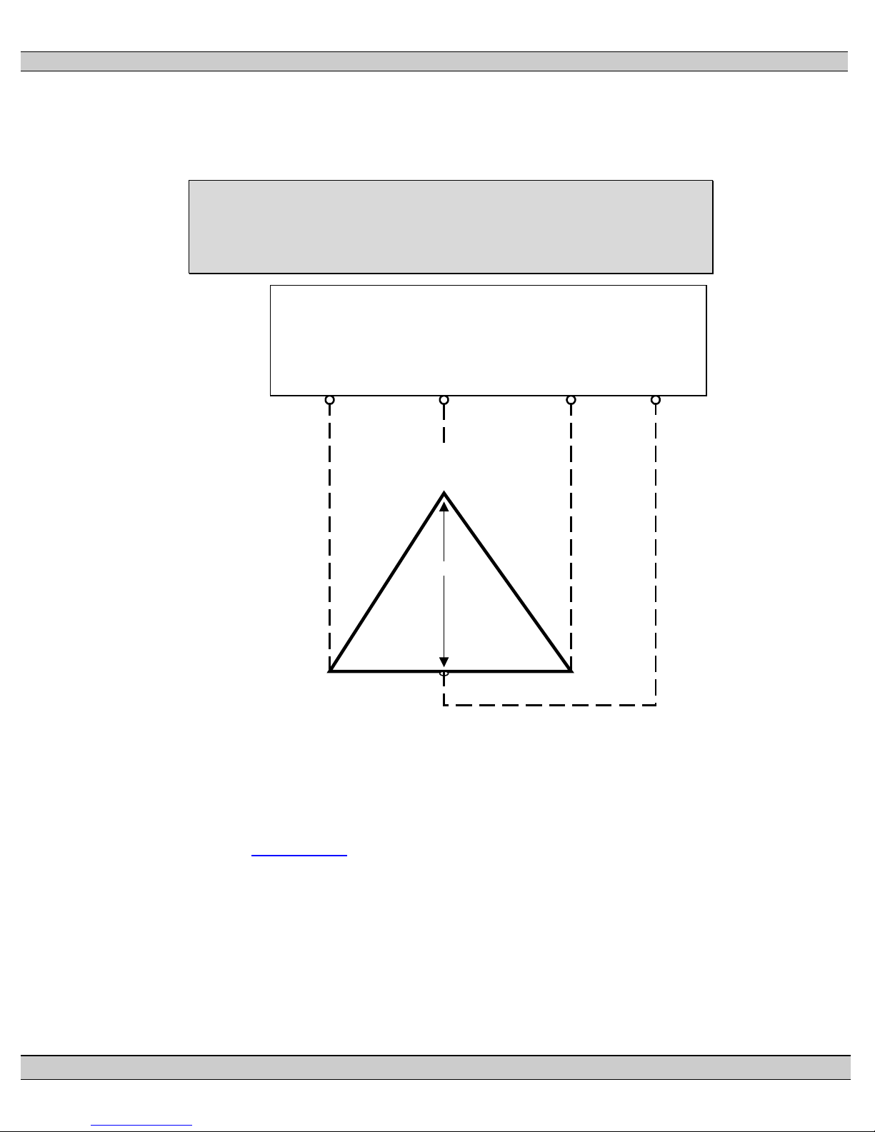
3.4.4 SYSTEM PHASING-HIGH LEG DELTA SYSTEMS
When the transfer switch is connected to 3 phase 4 wire delta systems, the “High” leg, must
be connected to Phase B of the Utility and/or Generator supply inputs to the ATS (Phase B,
PM140 REV 2 14/01/23 3 Thomson Power Systems
TS 910 TRANSFER SWITCH
208V
B
(Orange)
(High Leg)
C
(Yellow)
A
(Red)
N
(White)
PH A
(UA)
Automatic Transfer
Switch (Utility Supply)
PH B
(UB)
PH C
(UC)
Neural
(N)
120V 120V
240V 240V
colored Orange per “NEC 384-3(e)” identified as the leg with highest potential with reference
to ground). This will ensure the ATS control power that is internally connected between
phase A and neutral is maintained at 120VAC. Refer to figure below for further details.
WARNING
Failure to match correct system phasing will result in serious
damage to the Transfer Switch.
Note: For correct voltage sensing operation on High Leg Delta systems, the TSC 9
controller must have the configuration jumpers set at “240V” and “3PH” settings.
Refer to Section 18.15 TSC 9 CONFIG URATION I NSTRUCTI ONS of this manual
for further details.
3.4.5 Control Wiring
PM140 REV 2 14/01/23 4 Thomson Power Systems
All control wiring for engine start, load shed, alarm and remote test must be installed
in separate conduits from all power cabling and must utilize suitably sized conduits
per NEC requirements. All control wiring shall be sized for minimum #14 AWG.

TS 910 TRANSFER SWITCH
Control wiring type and voltage rating must also comply with NEC requirements and
local jurisdictions having authority.
3.4.6 Generator Set Automatic Operation
The standard T S 910 transfer switch operates in conjunction with any generator set
with remote automatic starting capabilities utilizing a 2 wire, remote start control
contact input. A dry contact is provided for remote generator starting control (contact
closes to start generator and opens to stop generator).
Optionally available is a Universal Generator Interface kit (UGI) which allows the TS
910 transfer switch to be applied to multiple types of generator sets utilizing 240V
remote starting control systems. Additional information on the Universal Generator
Interface kit can be obtained from our Website (
www.thomsontechnology.com).
3.4.7 Upstream Overcurrent Protection (Non-Service Entrance Rated TS 910)
Non-Service Entrance Rated TS 910 transfer switch models do not contain any
integral over current protection and require upstream over current protection devices
for both Utility and Generator sources. The standard TS 910 series Automatic
Transfer Switch is rated for 100% system load and is suitable for control of motors,
electric discharge lamps, tungsten filament lamps, and electric heating equipment
where the sum of motor full-load ampere ratings and the ampere ratings of other
loads do not exceed the ampere rating of the switch and the tungsten load does not
exceed 30 percent of the switch rating. Refer to
UPSTREAM CIRCUIT PROTECTIVE DEVICES
Section 17 REQUIREMENTS FOR
of this manual for further details.
3.4.8 Upstream Overcurrent Protection (Service Entrance Rated TS 910)
Service Entrance rated TS 910 transfer switch models contain integral over current
protection for the Utility source as standard. Service Entrance rated TS 910 transfer
switches do not
contain any integral over current protection f or the generator source
and requires upstream generator source over current protection. The Service
Entrance rated TS 910 is rated for 80% maximum continuous loading of all load
types. Refer to
PROTECTIVE DEVICES of this manual for further details.
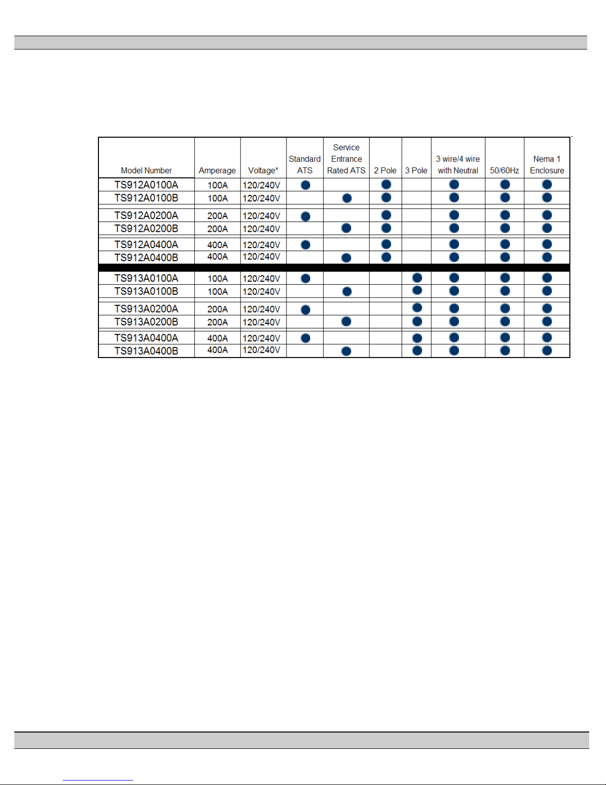
3.4.9 Withstand/Interrupting Current Ratings
Refer to electrical ratings table shown below for withstand/Interrupting current ratings.
Withstand/Interrupting short circuit current ratings shown require use of specific
types/manufacturers of upstream molded case circuit breakers. Refer t o
PM140 REV 2 14/01/23 5 Thomson Power Systems
Section 17 REQUIREMENTS FOR UPSTREAM CIRCUIT
Section 17

TS 910 TRANSFER SWITCH
TS912A0100A
STANDARD
2
240V
100A
10kA
SERVICE
ENTRANCE
TS912A0200A
STANDARD
2
240V
200A
10kA
SERVICE
ENTRANCE
TS912A0400A
STANDARD
2
240V
400A
25kA
SERVICE
ENTRANCE
SERVICE
ENTRANCE
SERVICE
ENTRANCE
SERVICE
ENTRANCE
REQUIREMENTS FOR UPSTRE AM CIRCUIT P ROTE CTIV E DEV ICES of th i s
manual for further details. Short circuit currents listed for Standard type ATS are
Withstand ratings. Short circuit currents listed for Service Entrance type ATS are
Interrupting ratings based on the ratings of the supplied utility service disconnect
circuit breaker utilized .
WARNING: Do not inst all the transfer switch on systems with higher available short
circuit current levels than listed below Failure to follow these instructions can
result in death, serious injury, or equipment damage.
SHORT
CIRCUIT
CURRENT
MODEL ATS TYPE POLES
TS912A0100B
TS912A0200B
TS912A0400B
MAX
VOLTAGE
AMPERAGE
2 240V 100A 10kA
2 240V 200A 10kA
2 240V 400A 25kA
TS913A0100A STANDARD 3 240V 100A 22kA
TS913A0100B
3 240V 100A 10kA
TS913A0200A STANDARD 3 240V 200A 25kA
TS913A0200B
3 240V 200A 10kA
TS913A0400A STANDARD 3 240V 400A 50kA
1
TS913A0400B
1
AMPS RMS Symmetrical
3.5 DIELECTRIC TESTING
Do not perform any high voltage dielectric testing on the transfer switch with the TSC
9 controller connected into the circuit as ser ious damage will occur to the controller.
The control circuit isolation plug connected to the TSC 9 must be removed if high
voltage dielectric testing is performed on the transfer switch.
PM140 REV 2 14/01/23 6 Thomson Power Systems
3 240V 400A 25kA
TS 910 TRANSFER SWITCH
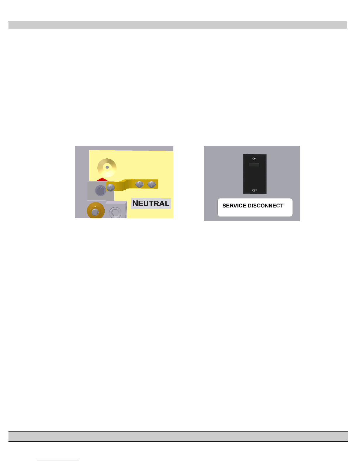
1. Connect the Bonding Strap
2. Apply the Service Disconnect
3.6 SERVICE DISCONNECT ATS CONFIGURATI ON
If the transfer switch is ordered with Service Entrance rat ing type and is to be used as
Service Equipment, following the procedure described below:
WARNING: The transfer switch must be de-energized prior to opening the enclosure
to access Neutral Bonding strap. Failure to follow these instructions can result in
death or serious injury.
to Neutral
label supplied with the ATS to the
front of the door under the circuit
breaker toggle
PM140 REV 2 14/01/23 7 Thomson Power Systems

TS 910 TRANSFER SWITCH
4 GENERAL DESCRIPTION
TS 910 Automatic Transfer Switches employ a power contactor switching unit with a m icroproces sor
based controller to automatically start a generator and transfer system load to a generator supply in
the event of a utility supply failure. System load is automatically re-transferred back to the utility
supply following restoration of the utility power source to within normal operating limits. All load
transfer sequences are “Open Transition” (i.e. “break-before-make”) utilizing an in-phase transfer
detection control sequence.
The TS 910 series transfer switches use a type TSC 9 microprocessor based controller. All
necessary control functions for fully automatic operation are provided by the TSC 9 transfer
controller. The TSC 9 controller is mounted inside the transfer switch enclosure and operating
status is provided via LED indicators that are visible though a fr ont panel opening on NEMA 1 rated
enclosures. For detailed information on the TSC 9 Transfer Switch controller, refer to
Section 18 of
this manual.
The standard TS 910 series Automatic Transfer Switch is rated for 100% system load and is suitable
for control of motors, electric discharge lamps, tungsten filament lamps, and electric heating
equipment where the sum of motor full-load ampere ratings and the ampere ratings of other loads do
not exceed the ampere rating of the switch and the tungsten load does not exceed 30 percent of the
switch rating.
Service Entrance Rated TS 910 Automatic Transfer Switch models are supplied with a utility supply
circuit breaker with over current protection. Refer to
Section 17 of this manual for detailed
information on over current protection.
PM140 REV 2 14/01/23 8 Thomson Power Systems
4.1 PRODUCT MODEL CODE
The type of TS 910 series transfer switch supplied is identified by way of a 11 digit product
code which appears on the equipment rating plate (MODEL) on the inside of the door of the
transfer switch.
TS 910 TRANSFER SWITCH
*Configurable for 120/208V Syste m Voltages
PM140 REV 2 14/01/23 9 Thomson Power Systems

TS 910 TRANSFER SWITCH
Model Code
Description
TS910-HTR
Enclosure Heater, 120VAC Fused, supplied from ATS
Load Bus
TS910-SPD1PH
Surge Protective Device, Single Phase Class 1,
120/240V
TS910-SPD3PH
Surge Protective Device, Three Phase Class 1,
120/208V
TS910-KWLS1PH2
kW Load Shed Control output contact, Single Phase,
ATS Load Bus
TS910-KWLS1PH4
kW Load Shed Control output contact, Single Phase,
ATS Load Bus
TS910-KWLS3PH2
kW Load Shed Control output contact, Three Phase,
ATS Load Bus
TS910-KWLS3PH4
kW Load Shed Control output contact, Three Phase,
ATS Load Bus
TS910-WMS
Wireless Remote Alarm Messaging Module
TS910-N3R100A
TS910-N3R400B
NEMA 3R Door, External Door Mountable to NEMA 1
TS910-UGI
Universal Generator Interface Start Kit
4.2 TS 910 OPTIONAL ACCESSORIES
The following optional ac ces sor i es may be or der ed as field installable kits.
One Stage, 0-200A Current Transformers connected to
One Stage, 0-400A Current Transformers connected to
One Stage, 0-200A Current Transformers connected to
One Stage, 0-400A Current Transformers connected to
TS910-N3R100B
TS910-N3R200A
TS910-N3R200B
TS913-N3R200A
TS913-N3R200B
TS910-N3R400A
ATS Enclosure (Specify matching ATS model number)
Additional information on TS 910 optional accessories can be obtained from our Website
(
www.thomsontechnology.com).
4.3 TYPICAL COMMISSIONING PROCEDURE S
CAUTION:
Commissioning procedures must be performed by qualified
personnel only.
PM140 REV 2 14/01/23 10 Thomson Power Systems
Note: The TYPICAL AUTOMATIC TRANSFE R SW ITCH COMMISSIONING PROCEDURES
MODEL SERIES TS 910 (attached as “Appendix A”) is provided for general information only

TS 910 TRANSFER SWITCH
ed voltage, a generator start sequence will be
timer, provided both
pertaining to typical site installations and applications. Contact Thoms on Power Systems for
further information as may be required.
5 GENERAL THEORY OF OPERATION
5.1 AUTOMATIC SEQUENCE OF OPERATION
Note: Time delays indicate d be lo w ar e f act or y def au lt s ettin gs on l y. Ref er to Section 18.15 of this
manual for alternate time delay settings available on TSC 9 Controller
UTILITY POWER FAIL
GEN START The generator will start following expiry of the 3 second Gen
GEN WARM-UP
TRANSFER TO GEN
LOAD SHED ACTIVATE
UTILITY POWER RETURN
TRANSFER TO UTILITY
LOAD SHED RESET
GEN COOL DOWN
When voltage drops on any phase of the utility supply below
70% of rat
initiated.
Start timer.
A generator warm-up per iod will be initiated once the gener ator
starts and reaches 80% rated voltage and 90% rated frequency.
The load will transfer to the gener ator supply followin g expiry of
the 10 second Gen Warm-up timer.
All non-essential loads connected to Load Shed control circuit
will be de-energized once generator transfers on load (If kW
Load Shed option is installed, refer to Section 18.16 of this
manual for further details).
When utility power is r estored to above 80% r ated volt age on all
phases, a utility power return sequence will be initiated.
The load will transfer from generator to utility power following
expiry of the 120 second Utility Return
generator and utility voltages are in-phase at time of transfer.
All non-essential loads connected to Load Shed control circuit
will be re-energized once load transfers to utility power.
The generator will automatically stop following expiry of the 2
minute Gen Cool Down timer.
5.2 SERVICE ENTRANCE AUTOMATIC TRANSFE R SWITCH OPERATION
5.2.1 OVER CURRENT TRIP
Should the utility breaker trip open due to an over current condition, TSC 9 transfer
controller will initiate an engine start signal and will permit transfer of the load to the
generator supply. The utility source will be locked out and the load will remain on the
generator supply until the Utility Service Entrance breaker is manually reset.
5.2.2 SERVICE DISCONNECT PROCEDURE
To initiate a Utility Supply Service Disconnect, follow procedure shown below:
PM140 REV 2 14/01/23 11 Thomson Power Systems

TS 910 TRANSFER SWITCH
5.2.2.1 TURN OFF GEN STARTING CONTROL: At the generator set, turn it’s automatic starting
control to OFF position to prevent generator set from automatically starting when the Utility
Service disconnect breaker is opened.
5.2.2.2 LOCK OPEN GENERATOR CIRCUIT BREAKER: At the generator set, OPEN its main
generator output power circuit breaker. Attach safety lockout padlock to the circ uit break er
to prevent unauthorized change in operating condition.
WARNING!
Failure to lock open the main generator output
circuit breaker may result in serious personal
injury or death due to electrical shock.
5.2.2.3 LOCK OPEN UTILTY SERVICE DISCONNECT BREAKER: At the transfer switch, OPEN
the Utility Service disconnect circuit breaker. Attach safety lockout padlock directly onto the
Service Disconnect Utility circuit breaker toggle hasp provided to prevent unauthorized
change in operating condition.
NOTE!
On NEMA 3R rated Transfer Switches, A door
locking Padlock hasp is also provided in cases
where the padlock does not fit behind the
NEMA 3R door when closed.
WARNING!
Failure to lock open the Utility Service
disconnect circuit breaker may result in serious
personal injury or death due to electrical shock.
Arc Flash and Shock Hazard. Will cause severe injury or death.
PM140 REV 2 14/01/23 12 Thomson Power Systems
DANGER!!!!

TS 910 TRANSFER SWITCH
Do not open equipment until ALL power sources are disconnected
This equipment must be installed and serviced only by qualified electrical
personnel utilizing safe work practices and appropriate Personal Protective
Equipment (PPE). Failure to do so may cause personal injury or death
5.2.3 RETURN FROM SERVICE DISCONNECT MODE
To return the system back to automatic operation following a Service Disconnect
mode, follow procedure shown below:
5.2.3.1 CLOSE ATS ENCLOSURE DOOR: Prior to Load re-energization, ensure the transfer
switch enclosure door/front cover is adequately closed with all provided fasteners.
5.2.3.2 CLOSE UITLITY SERVICE DISCONNECT BREAKER: T o r e-energ ize the load, remove the
padlock(s) from the Utility Service Disconnect Circuit Break er and or ATS door, and move
the circuit breaker to the CLOSED position. The Load will be re-energized and the transfer
switch will remain in the utility supply position.
5.2.3.3 CLOSE GENERATOR CIRCUIT BREAKER: At the generator set, re-close the main
generator output power circuit breaker.
5.2.3.4 RE-ENABLE AUTOMATIC GEN STARTING CONTROL: At the generator set, turn its
automatic starting control back to the AUTOMATIC position to return the system back to
fully automatic operation.
PM140 REV 2 14/01/23 13 Thomson Power Systems

TS 910 TRANSFER SWITCH
6 OVER CURRENT PROTECTION
6.1 STANDARD TS 910 AUTOMATIC TRANSFER SWITCH
The standard TS 910 Automatic Transfer Switch does not contain any integral over current
protection and requires upstream over current protection devices for both Utility and
Generator sources. The Standard TS 910 is rated for 100% continuous loading and can
withstand a maximum short circuit fault current as noted in
Section 17 of this manual. T he
standard TS 910 transfer switch model without integral over current protection is identified in
the product model code. Refer to
Section 4.1 of this manual for further details on model
coding.
6.2 SERVICE ENTRANCE RATED TS 9 10 AUTOMATIC TRANSFER SWITCH
TS 910 transfer switches have integral over current protection supplied on the Utility source
as standard. For transfer switches rated 100A through 400A, over current protection is nonadjustable thermal-magnetic type.
7 GENERAL NOTES ON SERVICING TRANSFER SWITCH MECHANISM
DANGER!!!!
Arc Flash and Shock Hazard. Will cause severe injury or death.
Do not open equipment until ALL power sources are disconnected
This equipment must be installed and serviced only by qualified electrical
personnel utilizing safe work practices and appropriate Personal Protective
Equipment (PPE). Failure to do so may cause personal injury or death
Only qualified personnel should undertake Service work. Failure to correctly maintain an
automatic transfer switch may present a hazard to life and equipment. Full operational
testing must be done prior to placing a transfer switch in service subsequent to any
maintenance or repair. Any service work involving electrical components requires highpotential testing to ensure that required insulation levels have been maintained.
When performing any service work on the transfer mechanism, it is imperative that the
following be observed:
To maintain mechanical integrity, ensure that:
• All fasteners are adequately tightened.
PM140 REV 2 14/01/23 14 Thomson Power Systems
 Loading...