

Marathon TS 870 Instructions Manual

TS 870
AUTOMATIC TRANSFER SWITCHES
With TSC 900 Controller
INSTALLATION, OPERATING &
9087A – 198th Street, Langley, BC Canada V1M 3B1 Telephone (604) 888-0110
Telefax (604) 888-3381 E-Mail: info@thomsonps.com www.thomsonps.com
SERVICE MANUAL
PM062 Rev 10 15/04/07


TS 870 TRANSFER SWITCH
TABLE OF CONTENTS
1. PRODUCT REVISION HISTORY 1
2. EQUIPMENT STORAGE 2
2.1. ENVIRONMENTAL CONDITIONS 2
3. NOTES TO INSTALLER 2
3.1. UPSTREAM CIRCUIT PROTECTIVE DEVICES/ELECTRICAL CONNECTIONS 3
3.2. TRANSFER SWITCHES WITH INTEGRAL OVER CURRENT PROTECTION 3
3.3. TRANSFER SWITCHES WITH MULTI-TAP VOLTAGE CAPABILITY 4
3.4. REMOTE START CONTACT FIELD WIRING 4
3.5. DIELECTRIC TESTING 5
3.6. INSTALLATION OF OPEN TYPE TRANSFER SWITCHES 5
3.7. MOUNTING OF ENCLOSED TRANSFER SWITCHES 5
4. GENERAL DESCRIPTION 8
4.1. PRODUCT MODEL CODE 10
4.2. TYPICAL COMMISSIONING PROCEDURES 11
5. GENERAL THEORY OF OPERATION 11
5.1. STANDARD AUTOMATIC TRANSFER SWITCH 11
5.2. SERVICE ENTRANCE AUTOMATIC TRANSFER SWITCH 12
5.3. TEST MODES 16
6. OVER CURRENT PROTECTION 16
6.1. STANDARD TS 870 AUTOMATIC TRANSFER SWITCH 16
6.2. OPTIONAL TS 870 AUTOMATIC TRANSFER SWITCH WITH INTEGRAL OVER
CURRENT PROTECTION 16
7. GENERAL NOTES ON SERVICING TRANSFER SWITCH MECHANISM 18
8. TRANSFER SWITCH MECHANISM – 100A-800A, S STYLE 20
8.1. MANUAL OPERATION 20
PM062 REV 10 15/04/07 Thomson Power Systems

TS 870 TRANSFER SWITCH
9. TRANSFER SWITCH MECHANISM –1000A-1200A, T-STYLE 22
9.1. MANUAL OPERATION 22
10. RECOMMENDED MAINTENANCE 23
11. FRONT VIEW (TYPICAL) 3 / 4 POLE 100A-250A S-STYLE TRANSFER
MECHANISM 25
12. FRONT VIEW (TYPICAL) 3 POLE 400A-800A S-STYLE TRANSFER MECHANISM
(MECHANISM FRONT COVER REMOVED) 26
13. FRONT VIEW (TYPICAL) 3 / 4 POLE 1000A-1200A T-STYLE TRANSFER
MECHANISM 27
14. CONNECTION CONFIGURATION OPTIONS 28
CABLE TERMINAL INFORMATION 29
15. REQUIREMENTS FOR UPSTREAM CIRCUIT PROTECTIVE DEVICES 29
15.1. WITHSTAND CURRENT RATINGS (ALL MODELS WITHOUT INTEGRAL
OVERCURRENT PROTECTION OPTION) 29
15.2. INTERRUPTING CAPACITY CURRENT RATINGS (ALL MODELS WITH INTEGRAL
OVERCURRENT PROTECTION OPTION) 30
16. GROUND FAULT SITE TEST REQUIREMENTS 30
16.1. PERFORMANCE TEST 30
17. TROUBLESHOOTING 32
18. REPLACEMENT PARTS 36
19. PRODUCT RETURN POLICY 37
20. NOTES 38
21. PERFORMANCE TEST FORM 39
APPENDIX A – TYPICAL TS 870 ATS COMMISIONING PROCEDURE
APPENDIX B – TS 870 SYSTEM VOLTAGE CHANGE PROCEDURE
APPENDIX C –SEISMIC CERTIFICATE
PM062 REV 10 15/04/07 Thomson Power Systems

TS 870 TRANSFER SWITCH
Rev 0 04/11/19
Original release.
Rev 1 05/03/08
Changes to incorporate reversing style ATS Motor for 100-250A
transfer switches.
Rev 2 05/05/26
Revisions to Section 8 and Section 18.
Rev 3 06/05/08
Revisions to Section 15.
Rev 4 07/07/31
Changes to Incorporate new S-Style 400A mechanism
Rev 5 08/03/05
Changes to Incorporate new S-Style mechanism (100A, 150A,
200A, 250A, 600A, 800A)
Rev 6 08/08/01
Changes to Incorporate optional TSC 80e Transfer Controller
Rev 7 09/01/01
Changes to Incorporate standard TSC 80e Transfer Controller
Rev 8 10/01/25
Changes to Incorporate Seismic Certification and Mounting
Requirements
Rev 9 14/01/08
Update to Marathon Thomson Power System Logo
Rev 10 15/04/07
Changes to incorporate TSC 900 Transfer Switch Controller
1. PRODUCT REVISION HISTORY
The following information provides an historical summary of changes made to this product since the
original release.
Operating & Service Manual Version
Contact Thomson Power Systems, to obtain applicable instruction manuals or if in doubt
about any matter relating to installation, operation or maintenance. Soft copy of the most
current version is available at www.thomsonps.com.
NOTE: All information contained in this manual is for reference only and is subject to
change without notice.
Related Product Instruction Manuals
TS 870 Quick Start Instruction Manual, PM150
TSC 900 Transfer Switch Controller, PM151
TSC 900 ModbusTM Communication, PM152
Contact Thomson Power Systems, to obtain these instruction manuals. Soft copy of the most
current versions of these manuals are available at www.thomsonps.com.
PM062 REV 10 15/04/07 1 Thomson Power Systems

TS 870 TRANSFER SWITCH
2. EQUIPMENT STORAGE
The following procedures are required for correct storage of the transfer switch prior to installation.
2.1. ENVIRONMENTAL CONDITIONS
CAUTION!!!
Failure to store and operate equipment under the specified environmental conditions may
cause equipment damage and void warranty.
2.1.1. EQUIPMENT STORAGE
The transfer switch shall be stored in an environment with a temperature range not
exceeding -4° to +158° Fahrenheit (-20° to +70° Celsius) and a humidity range not
exceeding 5%-95% non-condensing. Before storing, unpack sufficiently to check for
concealed damage. If concealed damage is found, notify the ATS supplier and the
Carrier immediately. Repack with the original, or equivalent packing materials. Protect
from physical damage. Do not stack. Store indoors in a clean, dry, well ventilated
area free of corrosive agents including fumes, salt and concrete/cement dust. Apply
heat as necessary to prevent condensation.
2.1.2. EQUIPMENT OPERATING
The transfer switch shall be operated in an environment with a temperature range not
exceeding +5° to +122° Fahrenheit (-15° to +50° Celsius) and a humidity range not
exceeding 5%-95% non-condensing.
3. NOTES TO INSTALLER
Arc Flash and Shock Hazard. Will cause severe injury or death.
Do not open equipment until ALL power sources are disconnected
This equipment must be installed and serviced only by qualified electrical
DANGER!!!!
personnel utilizing safe work practices and appropriate Personal Protective
Equipment (PPE). Failure to do so may cause personal injury or death
PM062 REV 10 15/04/07 2 Thomson Power Systems

TS 870 TRANSFER SWITCH
3.1. UPSTREAM CIRCUIT PROTECTIVE DEVICES/ELECTRICAL
CONNECTIONS
To ensure satisfactory installation of this equipment be sure to observe "Cable Terminal
Information” regarding power cable connection tightness and "Requirements for Upstream
Circuit Protective Devices" located in this manual.
All mechanical and electrical connections must be checked for tightness prior to placing this
equipment in service to ensure proper operation and to validate applicable warranty
coverage.
3.2. TRANSFER SWITCHES WITH INTEGRAL OVER CURRENT PROTECTION
For models of transfer switch with integral over current protection, the over current protection
must be set prior to operation. The equipment will be shipped from the factory with a longtime current setting of 100% (of the equipment rating) and maximum shorttime/instantaneous current and time delay settings.
WARNING!
Do Not Energize this equipment until
device settings have been verified to
ensure proper system protection &
coordination. Failure to do so may
result in equipment failure.
Refer to Section 5.2.2 of this manual for additional information on operation of the Transfer
switch following an over current trip condition.
Refer to information supplied with the transfer switch documentation package for adjustment
procedures on the power switching units over current protection trip unit. Contact the factory
if any additional information is required.
PM062 REV 10 15/04/07 3 Thomson Power Systems

TS 870 TRANSFER SWITCH
3.3. TRANSFER SWITCHES WITH MULTI-TAP VOLTAGE CAPABILITY
If the transfer switch has programmable multi-tap voltage capability (i.e. ATS Model Code
with Voltage Code “Y”), confirm the transfer switch has been configured for the correct
system voltage prior to installation.
WARNING!
Failure to confirm and match transfer
switch voltage with the system voltage
could cause serious equipment damage.
The voltage selections and connections are shown on the drawings supplied with each
transfer switch. The factory default settings will be indicated on the calibration label attached
on the inside of the enclosure door (supplied loose on open style models). A blank label is
included to record the applicable settings if the configuration is changed from the factory
default settings.
To change the transfer switch voltage, refer to “TS 870 SYSTEM VOLTAGE CHANGE
PROCEDURE” (attached as “Appendix B). Contact Thomson Power Systems for further
information as may be required.
3.4. REMOTE START CONTACT FIELD WIRING
As a minimum, the remote engine start control field wiring shall conform to the local
regulatory authority on electrical installations. Field wiring of a remote start contact
from a transfer switch to a control panel should conform to the following guidelines to
avoid possible controller malfunction and/or damage.
3.5.1. Minimum #14 AWG (2.5mm2) wire size shall be used for distances up to 100ft
(30m)1). For distances exceeding 100 ft. (30m) consult Thomson Power
Systems
3.5.2. Remote start contact wires should be run in a separate conduit.
3.5.3. Avoid wiring near AC power cables to prevent pick-up of induced voltages.
3.5.4. An interposing relay may be required if field-wiring distance is excessively
long (i.e. greater than 100 feet (30m)) and/or if a remote contact has a
resistance of greater than 5.0 ohms.
3.5.5. The remote start contact must be voltage free (i.e. dry contact). The use of a
“powered” contact will damage the transfer controller.
PM062 REV 10 15/04/07 4 Thomson Power Systems

TS 870 TRANSFER SWITCH
3.5. DIELECTRIC TESTING
Do not perform any high voltage dielectric testing on the transfer switch with the TSC
900 controller connected into the circuit as serious damage will occur to the
controller. All AC control fuses and control circuit isolation plugs connected to the
TSC 900 must be removed if high voltage dielectric testing is performed on the
transfer switch.
3.6. INSTALLATION OF OPEN TYPE TRANSFER SWITCHES
Please refer to the factory for additional information.
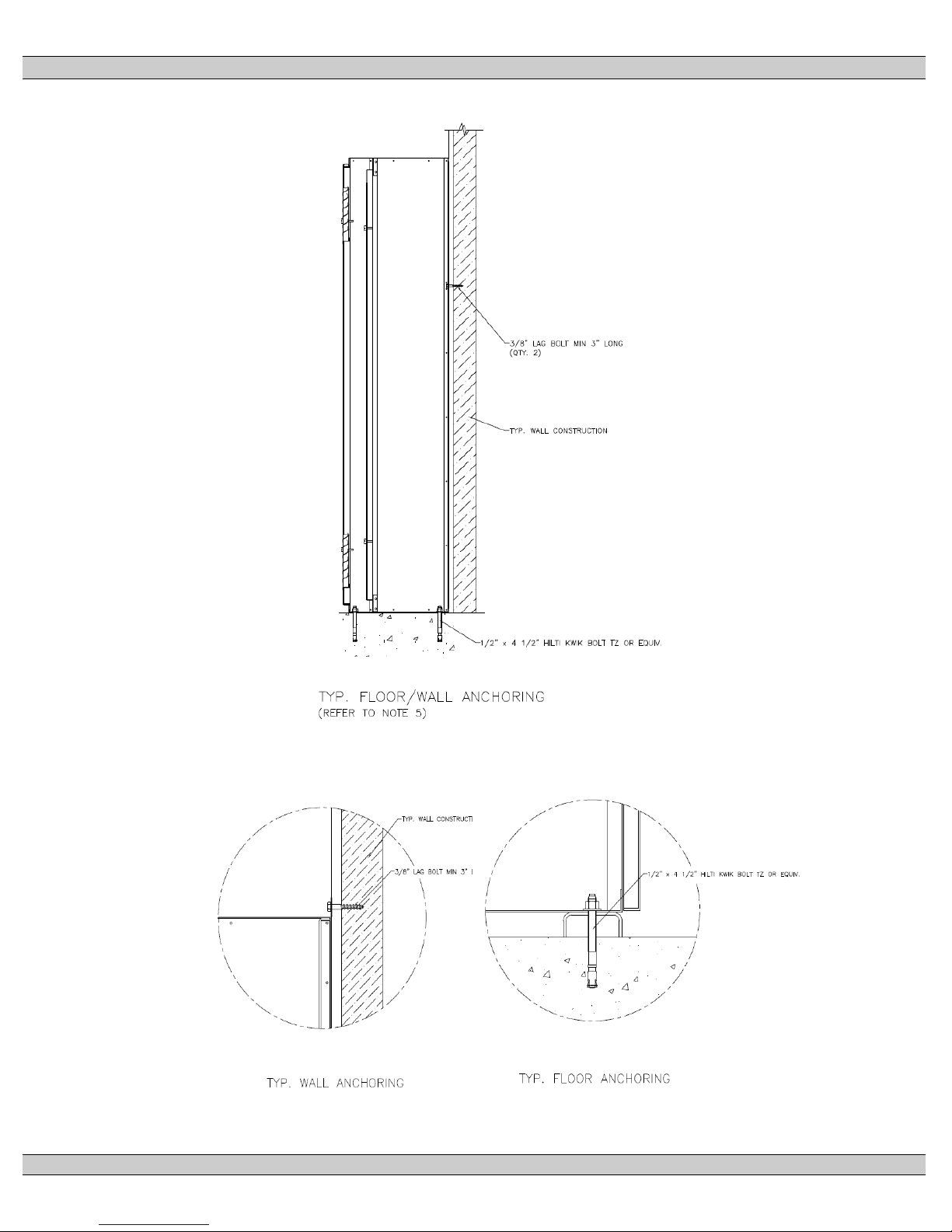
3.7. MOUNTING OF ENCLOSED TRANSFER SWITCHES
Model TS870 Automatic Transfer Switches and Automatic Transfer and Bypass
Isolation Switches in "standard" enclosures are seismic certified under AC156
building code for non-structural components.
"Standard" enclosures are all transfer switch enclosures Thomson Power Systems
offers in NEMA 1, NEMA 2, NEMA 3R and NEMA 4X for the above listed product. If
a customer requests a custom enclosure it would not be covered under the generic
certificate; if certification were a requirement Consult factory before ordering.
The Automatic Transfer Switches are qualified to the highest known level in North
America; based on site class D. Specifically this is a spectral acceleration of 342%.
The transfer switch must be installed per the anchoring details provided for seismic
qualification. The equipment can be mounted in alternate means and still qualify if a
qualified Civil Engineer designs the alternate method of anchoring.
PM062 REV 10 15/04/07 5 Thomson Power Systems
TS 870 TRANSFER SWITCH
PM062 REV 10 15/04/07 6 Thomson Power Systems

Anchoring Notes:
1. Anchoring must be designed according to IBC 2006 or latest version.
2. The anchoring details shown are recommended according to the seismic
certification; design Engineer may use alternate anchors within the scope of IBC.
3. Wall anchors in concrete; use a typical concrete anchor as necessary.
4. Expansion anchors as shown. To be installed according to manufacturer's
recommendation.
5. The 800-1200A NEMA 3R ATS enclosure may be floor/wall mounted or it may be
free standing (floor mounted only); If free standing it must be a minimum of 12"
(305mm) away from pipes, conduits or other obstructions to allow for sway during a
seismic event.
TS 870 TRANSFER SWITCH
PM062 REV 10 15/04/07 7 Thomson Power Systems
TS 870 TRANSFER SWITCH
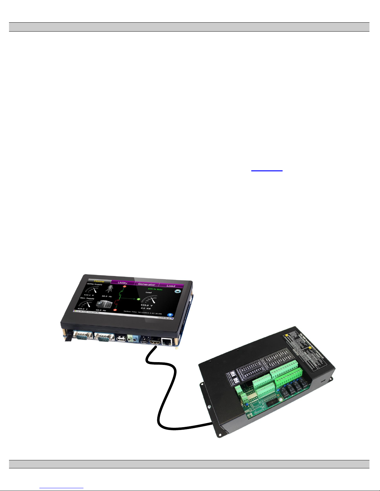
USB 2.0 Cable
GHC
SCU
4. GENERAL DESCRIPTION
Thomson Power Systems TS 870 series of Automatic Transfer Switches employ two mechanically
interlocked enclosed contact power switching units and a microprocessor based controller to
automatically transfer system load to a generator supply in the event of a utility supply failure.
System load is then automatically re-transferred back to the utility supply following restoration of the
utility power source to within normal operating limits.
The standard TS 870 series Automatic Transfer Switch is rated for 100% system load and requires
upstream over current protection. The TS 870 Automatic Transfer Switch may be supplied with
optional integral over current protection within the enclosed contact power switching units for
applications such as Service Entrance Rated equipment. Refer to Section 6 of this manual for
detailed information on over current protection.
The TS 870 series transfer switches use a type TSC 900 microprocessor based controller, which
provides all necessary control functions for fully automatic operation. The TSC 900 controller
consists of two parts; a front door mounted graphical touch screen display (GHC), and a switch
control unit (SCU) which is mounted inside the transfer switch door. The two parts are
interconnected via a USB 2.0 high speed communication cable which includes DC power.
PM062 REV 10 15/04/07 8 Thomson Power Systems

TS 870 TRANSFER SWITCH
For further information on the TSC 900 Transfer Controller, refer to separate instruction manual
PM151.
The power switching devices used for the Utility and Generator sources are operated by an
electrically driven motor mechanism in the transfer switch. The transfer switch motor utilizes the
power from the source to which the electrical load is being transferred. The mechanism provides a
positive mechanical interlock to prevent both power switching units from being closed at the same
time, which allows an open transition, “break-before-make” transfer sequence. The TSC 900
transfer controller provides a standard neutral position delay timer to allow adequate voltage decay
during transfer operation to prevent out of phase transfers.
Note: For the purpose of this manual, the following standard nomenclature is utilized:
Utility: to indicate the source of primary power
Generator: to indicate the source of standby power
Power switching device: to indicate the transfer switch power switching device.
PM062 REV 10 15/04/07 9 Thomson Power Systems
TS 870 TRANSFER SWITCH
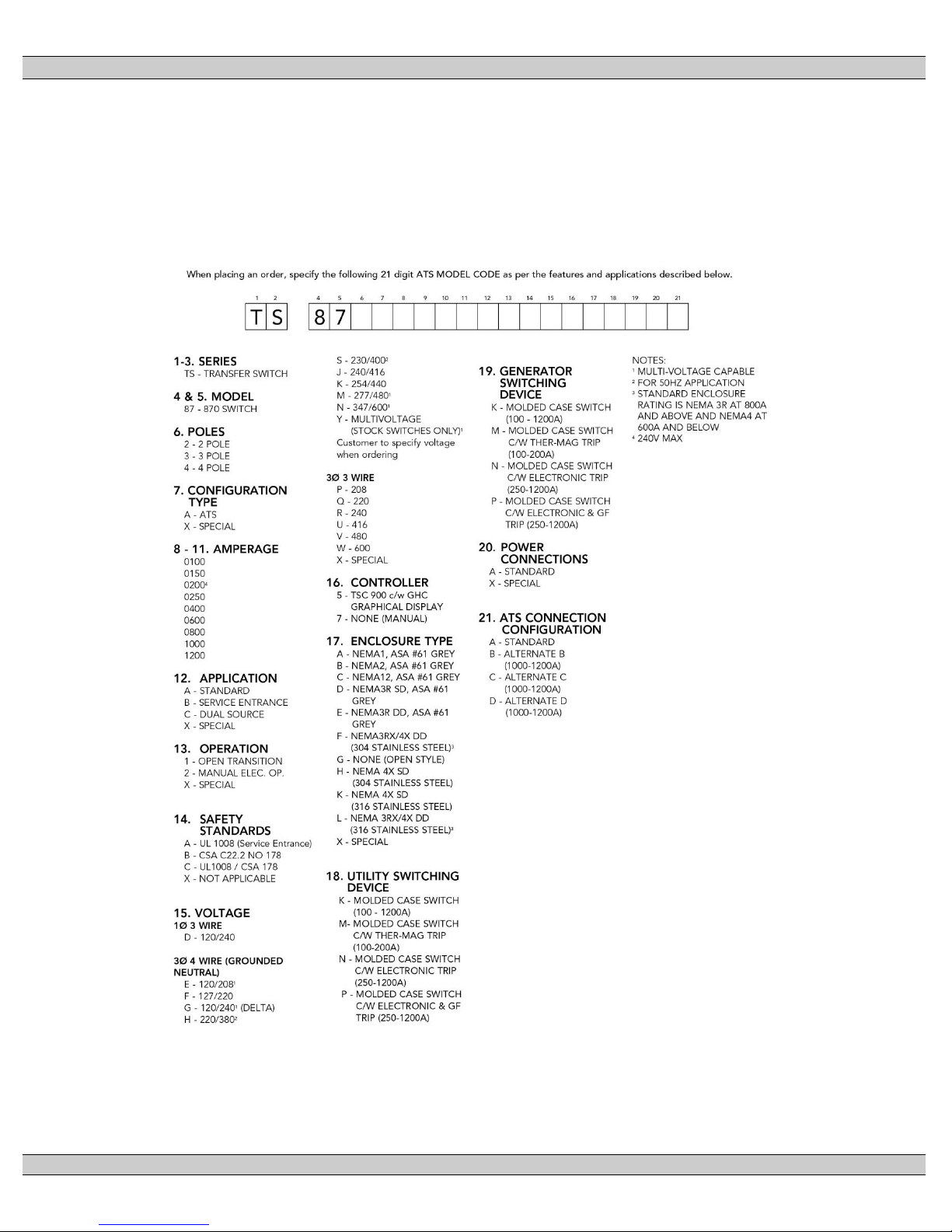
4.1. PRODUCT MODEL CODE
The type of TS 870 series transfer switch supplied is identified by way of a 21 digit product
code which appears on the equipment rating plate (MODEL) on the door of the transfer
switch, and on the transfer switch drawings. The model code structure and definitions are as
follows:
PM062 REV 10 15/04/07 10 Thomson Power Systems

TS 870 TRANSFER SWITCH
4.2. TYPICAL COMMISSIONING PROCEDURES
CAUTION:
Commissioning procedures must be performed by qualified
personnel only. Ensure the Automatic Transfer Switch
(ATS) ATS Power Chassis & Voltage Sensing Isolation
Plugs PL12 & PL 15 are disconnected prior to energizing
the supply sources. Manually place the transfer switch
mechanism in the neutral position prior to applying power.
Failure to do so may result in equipment failure or personal
injury.
Note: The TYPICAL AUTOMATIC TRANSFER SWITCH COMMISSIONING PROCEDURES
MODEL SERIES TS 870 (attached as “Appendix A”) is provided for general information only
pertaining to typical site installations and applications. Contact Thomson Power Systems for
further information as may be required.
5. GENERAL THEORY OF OPERATION
5.1. STANDARD AUTOMATIC TRANSFER SWITCH
5.1.1. NORMAL OPERATION
When utility supply voltage drops below a preset nominal value (adjustable from 70%
to 100% of nominal) on any phase, an engine start delay circuit is initiated and the
transfer to utility supply signal will be removed (i.e. contact opening). Following expiry
of the engine start delay period (adjustable from 0 to 60 sec.) an engine start signal
(contact closure) will be given.
Once the engine starts, the transfer switch controller will monitor the generator
voltage and frequency levels. Once the generator voltage and frequency rises above
preset values (adjustable from 70% to 95% of nominal), the engine warm-up timer will
be initiated. Once the warm-up timer expires (adjustable from 0 to 60 min.), the
Transfer to Generator Supply signal (contact closure) will be given to the transfer
switch mechanism. The load will then transfer from the utility supply to the generator
supply via the motor driven mechanism.
PM062 REV 10 15/04/07 11 Thomson Power Systems

TS 870 TRANSFER SWITCH
The generator will continue to supply the load until the utility supply has returned.
The retransfer sequence is completed as follows: when the utility supply voltage is
restored to above the preset values (adjustable from 70% to 95% of nominal) on all
phases, a transfer return delay circuit will be initiated. Following expiry of the Utility
Return Timer (adjustable from 0 to 60 min.), the Transfer to Generator Supply signal
will be removed (contact opening), then the Transfer to Utility Supply signal (contact
closure) will be given to the transfer switch mechanism. The load will then retransfer
the load from the generator supply back to the utility supply. Note: A neutral delay
timer circuit will delay the transfer sequence in the neutral position (i.e. both power
switching devices open) until the neutral delay time period expires (adjustable from 0
to 60 seconds).
An engine cooldown timer circuit will be initiated once the load is transferred from the
generator supply. Following expiry of the cooldown delay period (adjustable from 0 to
60 minutes), the engine start signal will be removed (contact opening) to initiate
stopping of the generator set.
5.2. SERVICE ENTRANCE AUTOMATIC TRANSFER SWITCH
Note: This applies only to service entrance transfer switches
5.2.1. NORMAL OPERATION
Under normal conditions, the load is energized from the utility supply through the
closed utility transfer power switching device. If the utility power fails, the generator
will start and the load will be re-energized via the closed generator transfer power
switching device.
In the normal operating mode, the Service Disconnect switch shall be in the
“energized” position.
5.2.2. OVER CURRENT TRIP
Should the utility power switching device trip open due to an over current condition,
TSC 900 transfer controller will initiate an engine start signal and will permit transfer
of the load to the generator supply. The utility source will be locked out and the load
will remain on the generator supply until the TSC 900 alarm signal is manually reset.
Refer to the TSC 900 Instruction Manual for further details on Transfer Fail operation.
PM062 REV 10 15/04/07 12 Thomson Power Systems

TS 870 TRANSFER SWITCH
Should the generator power switching device trip open due to an over current
condition, TSC 900 transfer controller will initiate transfer of the load to the utility
supply. The generator source will be locked out and the load will remain on the utility
supply until the TSC 900 alarm signal is manually reset.
5.2.3. SERVICE DISCONNECT PROCEDURE
To perform a service disconnect (i.e. to disconnect the utility and generator supplies),
the following procedure is required:
1. Move the "Service Disconnect" control switch located on the door of the
transfer switch to the "Transfer to Neutral” position and wait 2 seconds for
ATS to transfer to neutral position.
2. Once the ATS has transferred to the neutral position, move the "Service
Disconnect" control switch to the "Disconnected" position.
3. Verify that the "Service Disconnected" pilot light is illuminated. If the Light
is illuminated, the service has been successfully disconnected and it is
safe to perform any maintenance procedures as required. In this
condition, the transfer switch is in the neutral position, with both utility and
generator transfer power switching devices open. The transfer switch will
remain in this condition, regardless of condition of the utility and generator
supplies.
NOTE: If the Service Disconnect Light is not illuminated, additional
procedures are required (refer to the following procedure #5.2.4).
4. Attach safety lockout padlock to the "Service Disconnect" control switch to
prevent unauthorized change in operating condition and verify transfer
switch door is locked closed. If the door is not locked, turn and remove
door key.
WARNING!
Close and lock the transfer switch
enclosure door before connecting
power sources.
5. To re-energize the load, remove the padlock(s) from the service disconnect
control switch, and move the switch to the “energized” position. The transfer
switch will immediately return to the utility or generator supply if within normal
operating limits.
PM062 REV 10 15/04/07 13 Thomson Power Systems
 Loading...