

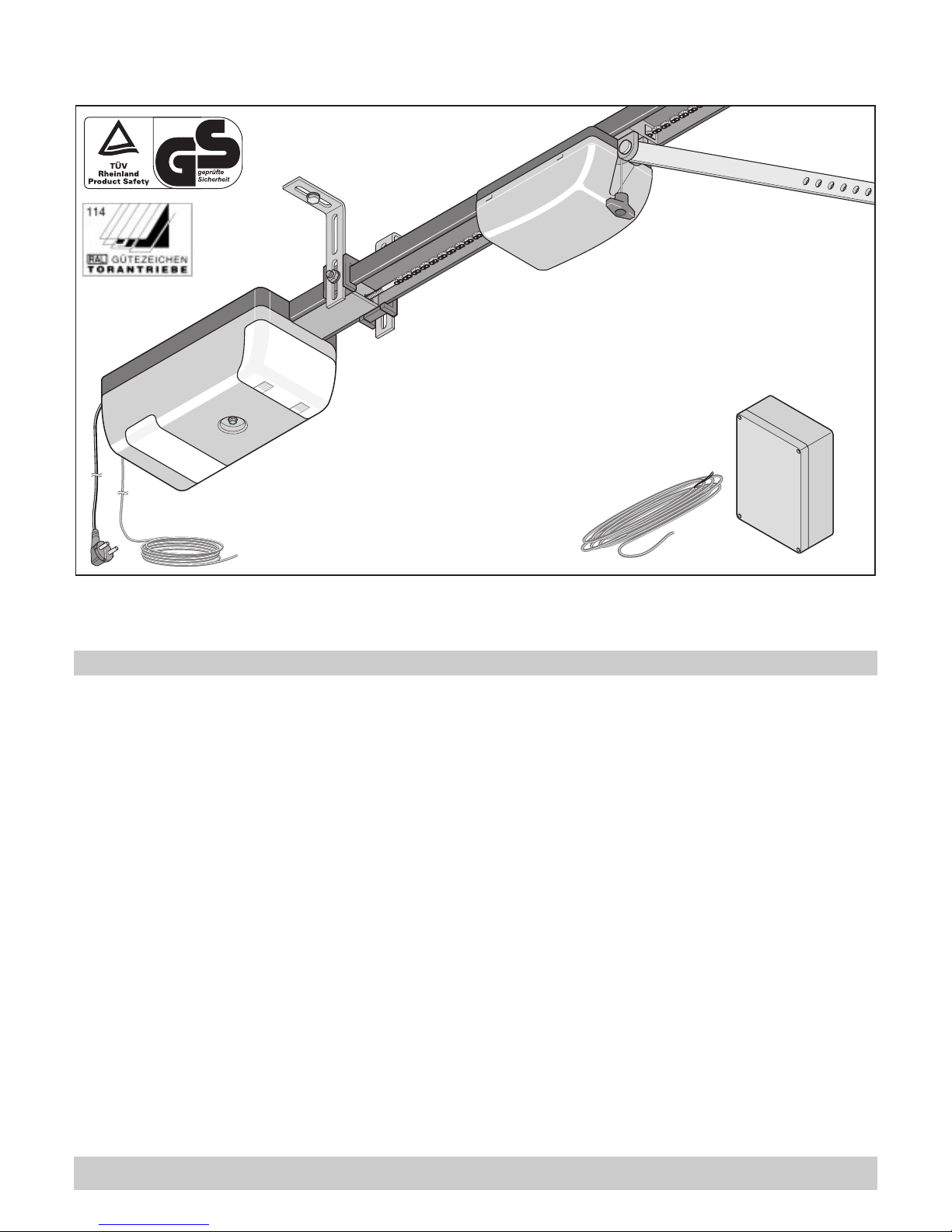
Marathon tiga 800 SL, tiga 1100 SL Instructions Manual
Installation and Operating Instructions 1 - 33
46621V001-342004-0-OCE-Rev.A
marathon tiga 800 SL, marathon tiga 1100 SL

Table of Contents
1
General Information . . . . . . . . . . . . . . . . . . . . . . . . . . . . 2
Symbols 2
Safety Instructions 2
Intended Use 2
Te r ms 3
Functional description 3
Maximum door dimensions* 4
Technical Data 4
EU Manufacturer’s Declaration 4
Preparations for Installation . . . . . . . . . . . . . . . . . . . . . 5
Safety Instructions 5
Scope of Supply 5
Safety Instructions 6
Door Types and Special Accessories* 6
Installation Tips 6
Assembly . . . . . . . . . . . . . . . . . . . . . . . . . . . . . . . . . . . . 6
Accessories 7
Operator Pre-installation 8
Installing the Operator 8
Mounting the control unit 10
Signal light: Installation + connection 10
Inside button: Installation + connection 11
Install the socket outlet 11
Commissioning . . . . . . . . . . . . . . . . . . . . . . . . . . . . . . . 12
Safety Instructions 12
Setting Door OPEN + CLOSED End Positions 12
“Teaching” the Operator 12
Checking End Positions OPEN + CLOSED 13
Checking the emergency release 13
Checking the Force Setting 13
Setting the Maximum Force 13
“Teaching” the remote control transmitter 13
Operation and Handling . . . . . . . . . . . . . . . . . . . . . . . . 15
Safety Instructions 15
Open and close the door 15
Emergency Release 15
Resetting the control unit 15
Adjusting warning time OPEN 15
Setting the CLOSE warning time 15
Setting the clearance time 15
Setting the hold open time 15
Priority switching with time relay 16
Radio Receiver 16
Description of Display and Push-buttons 16
“Teaching” the remote control transmitter 16
Functions . . . . . . . . . . . . . . . . . . . . . . . . . . . . . . . . . . . . 17
Obstruction in the door travel path: Recognition and behaviour (DIP
1) 17
Safety connectionfunction 1 (DIP 2) 17
Priority switching (DIP 3) 17
Premature closing (DIP 4) 17
Extending the hold open time (DIP 5) 17
BackJump (DIP 6) 17
Display type red signal light (DIP 7) 17
Test mode (DIP 8) 17
Connections. . . . . . . . . . . . . . . . . . . . . . . . . . . . . . . . . . 18
Terminal bar, 24-pole 18
Trolley board 18
Connect button 1 (inside) 18
Connect button 2 (outside) 18
Connecting photoelectric cell 1 18
Connect 8.2 k Ohm strip 18
Connecting photoelectric cell 2 19
24 Volt Connection 19
12 Volt Connection 19
Connecting an External Aerial 19
Connecting Fraba System 19
Connections for Signal Light Controller 1 20
Connections for Signal Light Control Unit 2 20
Accessories . . . . . . . . . . . . . . . . . . . . . . . . . . . . . . . . . . 21
Maintenance and Care . . . . . . . . . . . . . . . . . . . . . . . . . 26
Important Information 26
Regular Checks 27
Miscellaneous . . . . . . . . . . . . . . . . . . . . . . . . . . . . . . . . 28
Disassembly 28
Correct Disposal 28
Warranty and After-Sales Service 28
Help in case of malfunction . . . . . . . . . . . . . . . . . . . . . 29
Troubleshooting Tips 29
Replacement part list marathon tiga 800 SL . . . . . . . 31
Replacement part list marathon tiga 1100 SL . . . . . . 32
Schematic diagram . . . . . . . . . . . . . . . . . . . . . . . . . . . . 33
2
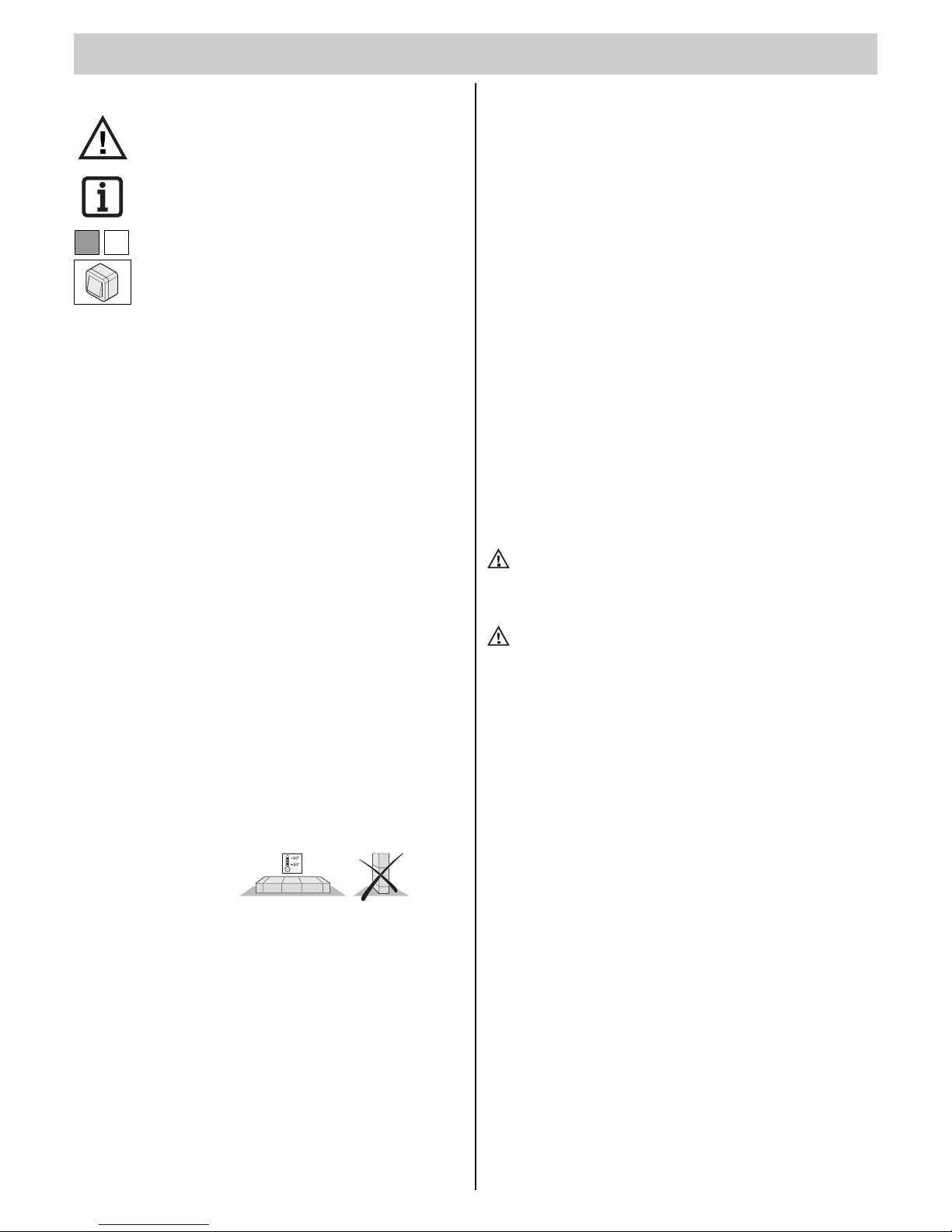
Symbols
Exclamation mark:
Indicates a potential risk! Failure to follow instructions may
result in serious injuries!
Note symbol:
Information, useful advice!
Refers to the relevant illustration in the introduction or main text.
This illustration of a button represents all types of buttons:
such as key-activated buttons, pull-cord switches, etc.
Safety Instructions
General
• These installation and operating instructions must be read, understood,
and complied with, by the person who installs, operates, or maintains the
operator.
• Only specialised personnel should assemble, connect, and commission
the operator.
• Only install the operator to correctly aligned and weight-balanced doors.
An incorrectly aligned door can cause serious injury or damage to the
operator.
• The manufacturer cannot be made liable for any damage or disruptions
to operation occurring due to non-compliance with the Installation and
Operating Instructions.
• Ensure that these Installation and Operating Instructions remain in the
garage in an easily accessible location.
• Observe and comply with accident prevention directives and applicable
standards in the respective countries.
• Observe and comply with the directive on “Power-driven Windows, Doors
and Gates - ZH 1/494” issued by the Employers’ Liability Insurance Association. (Applicable in Germany for the operator)
• Always disconnect (unplug) the operator from the mains supply before
performing any work on the operator.
• Use only manufacturer’s original replacement parts, accessories, and
mounting material.
Storage
• The operator may only be stored indoors, in a dry, enclosed environment
at an ambient temperature between -20°C and +50°C.
• The operator should be stored horizontally.
Operation
• The operator may only be activated if a hazard-free force tolerance has
been set, or if safety is ensured at all times through other safety fixtures.
The force tolerance must be set as low as possible in order to ensure
that the door’s closing force does not constitute a danger, see section
“Force Setting”.
• Keep your hands clear of a moving door or any moving parts.
• Keep children, disabled persons and animals away from the door.
• Only drive into the garage when the door is completely open and the signal light is green.
• There is a risk of persons getting trapped or cutting themselves in/on the
door system’s moving parts or the edges where it closes.
• If the door is not equipped with a slip door, or if there is no separate
access to the garage, then install an emergency release system (emergency release lock or Bowden cable) that can be activated from outside
of the garage.
(1)1
Radio Remote Control
• The radio remote control may only be used for equipment and systems
where defective remote operation of the transmitter or receiver does not
constitute a risk to people, animals or objects, or in cases where this risk
is eliminated by means of additional safety fixtures.
• The user must be made aware of the fact that the remote control of
equipment with accident risk potential may only occur, if at all, when the
equipment concerned is clearly visible.
• Radio remote control may only be used if door travel can be supervised,
and if there are no persons or objects in the travel range.
• Store the remote control transmitter so that there is no risk of it being
accidentally activated; e.g. by children or animals.
• The operator of this radio-controlled equipment is in no way protected
from interference from other telecommunications systems and facilities
(e.g. other radio-controlled equipment that is licensed to operate at the
same frequency range). Should serious interference be encountered,
then please contact your nearest telecommunications office with interference measuring facilities (radio signal localisation)!
• Do not use the remote control transmitter near locations or installations
that are susceptible to radio interference (such as airports or hospitals).
Rating Plate
The rating plate is located on the cover of the control unit housing.
Exact type designation and date of manufacture (month/year) of the opera-
tor are indicated on the rating plate.
Intended Use
Attention! There is a risk of injury or property damage!
Always connect the slip-door safety mechanism to safety input 2
(terminals 8 + 9). If the slip-door safety mechanism is connected
to the trolley, then the operator will not recognise the door position.
Attention! Risk of serious damage to operator!
Do not open or close the door using the operator without first
adjusting the balance weight (springs tensioned). Otherwise, the
motor (gear system) might be seriously damaged.
• The operator is designed for the exclusive purpose of opening and closing doors. Any other use does not constitute intended use. Manufacturer
is not liable for damages that arise due to non-intended use. The risk is
borne solely by the operator. Non-intended use renders the warranty null
and void.
• Doors operating automatically with an operator must comply with the
standards and directives valid at the given time: e.g. EN 12604, EN
12605.
• The operator may only be used in a technically perfect condition, as
intended, in a safety-conscious and hazard-conscious manner, in compliance with the installation and operating instructions.
• Malfunctions that can impair safety must be resolved immediately.
• The door must be stable and warp-proof, i.e. it should not bend or warp
during opening or closing operations.
• The operator is unable to compensate for any defects in the door or for
its incorrect installation.
• Only use the operator in a dry, indoor environment where there is no risk
of explosion.
• Do not use the operator in rooms where a hostile
environment prevails (e.g. salty air).
General Information

General Information
3
Ter ms
Abbreviations
GI Signal light green inside
RI Signal light red inside
GO Signal light green outside
RO Signal light red outside
TorMinal
Programming device The door operator can be adjusted, or special functions can be set, with this unit. See “Accessories”.
“Teaching”
The operator “learns” the required time and the force that it requires to
open and close the door. The operator stores these values, which remain
intact even if there is a power failure.
Door OPEN
The door opens or it is already opened.
Door CLOSE
The door closes or it is already closed.
Warning time
Time prior to opening or closing; during this time the red signal lights flash
and thus indicate that the operator is in motion:
Door OPEN:
Warning time can be adjusted with the TorMinal in a range from 0...63.75
seconds, in intervals of .025 seconds, memory slot (mem) 027.
Factory setting is door OPEN: 4 seconds
Door CLOSE:
The warning time can be adjusted with the TorMinal in a range from
0...63.75 seconds, in intervals of .025 seconds, memory slot (mem) 027.
Factory setting is door CLOSE: 5 seconds
Hold open time
Time that the door remains open. The side (inside / outside) that initiated
the command to open the door gets the green signal. The door can only be
opened by a command issued via a push-button or remote control transmitter; it cannot be closed. When the door is opening, no command issued can
stop it from doing so.
If the door is closing automatically and a command is reissued, then the
door opens fully. Any command issued during the hold open time restarts
the hold open time.
The hold open time can be adjusted with the TorMinal in a range from
2...255 seconds, in 1 second increments, memory slot (mem) 031. Factory
setting: 30 seconds
Clearance time
Time in which the red signal lights are illuminated after expiration of the
hold open time; thus providing time for the persons or vehicles who had the
green light to clear the entries.
Clearance time can be adjusted with the TorMinal in a range from 0 ..63.75
seconds, in 0.25 second increments, memory slot (mem) 032.
Factory setting: 10 seconds
Inside
The side which is inside the garage or the parking area.
Outside
The side which is outside the garage or the parking area.
Command inside
Radio channel 1 or button connection 1 on terminal 2 + 3
(button line connected to the control unit)
Button or radio signal for opening the door from inside and thus drive authorisation for inside, signal light (GI) is green.
Command outside
Radio channel 2 or button connection 2 on terminal 4 + 5
Button or radio signal for opening the door from outside and thus drive
authorization for outside, signal light (GO) is green.
Command side
The side (inside or outside) that issues a command.
Functional description
The command inside/outside, which was first transmitted to the control unit,
has priority, regardless of whether it was transmitted via radio or button
connection.
Priority for “Command Outside” is set with DIP switch 3. As soon
as “Command Outside” is received the hold open time for inside
will be aborted and switched to drive authorization for outside
after the clearance time.
Operator behaviour at factory setting
Behaviour after power connection
Door closed and operator “taught”. All signal lights are switched off. Operator waits for a command from inside/outside. The first travel direction is
always door OPEN; if the door is already open, then the operator recognises this and switches the signal light to green on the side that gave the
command. Then the operator closes the door after the following individual
times expire: Warning, clearance and hold open time.
Behaviour after inside/outside command, door CLOSE
Sequence and display behaviour:
1. Command from inside/outside.
2. Door OPEN warning time starts. Red signal lights flash. Green signal
lights are switched off.
3. The operator opens the door. Red signal lights light up. Green signal
lights are switched off.
4. Door OPEN. Command side green signal light on. Red signal light is on
for the other side.
5. The set hold open time expires.
6. Warning time starts for door CLOSE. Red signal light flashes on the
command side. Red signal light lights up on the other side. Green
signal lights are switched off.
7. Clearance time starts. Red signal lights switch on. Green signal lights
are switched off.
8. The operator closes the door Red signal lights switch on. Green signal
lights are switched off.
9. Door CLOSED All signal lights are switched off.
Behaviour after command inside and then command
outside, door CLOSE
Sequence and display behaviour:
1. Command from inside.
2. Door OPEN warning time starts. Red signal lights flash. Green signal
lights are switched off.
3. The operator opens the door. Red signal lights light up. Green signal
lights are switched off.
4. Door OPEN. Command side green signal light on. Red signal light is on
for the other side.
5. Command from outside. The hold open time which was set for the pre-
vious command expires.
6. Clearance time starts. Red signal lights switch on. Green signal lights
are switched off.
7. Outside gets drive authorization. Command side green signal light
lights up. Red signal light is on for the other side.
8. The set hold open time expires.
9. Warning time starts for door CLOSE. Outside red signal light blinks.
Inside red signal light lights up. Green signal lights are switched off.
10. Clearance time starts. Red signal lights switch on. Green signal lights
are switched off.
11. The operator closes the door Red signal lights switch on. Green signal
lights are switched off.
12. Door CLOSED All signal lights off.

General Information
4
Maximum door dimensions*
marathon tiga 800 SL 1100 SL
max. width:
- Up-and-over door 6000 8000 mm
- Sectional door: 6000 8000 mm
- Wing door **: 2800 2800 mm
- Side sectional door
Rail 2600 2350 2350 mm
- Up-and-over door: 5500 7500 mm
Height (app.)
- Swing door:
Rail 2600 2600 2600 mm
- Sectional door:
Rail 2600 2350 2350 mm
- Wing door **: 3000 3500 mm
- Side sectional door
3000 3500 mm
- Up-and-over door:
Rail 2600 1900 1900 mm
Duration of operation: 40 40 %
* door conforming to EN 12604, EN 12605
** with standard wing-door hinges prod. no. 1501.
Larger doors are only available on request. For higher doors, appropriate
rail lengths must be ordered, or the necessary height can be achieved by
installing rail extensions (see accessories).
Technical Data
General
Rated voltage: 220 ...240 V/AC
Rated frequency: 50/60 Hz
Operating temp. range: -20 ...+50 °C
Safety class IP 20
Workplace-specific emission value < 75 dBA - operator only
marathon tiga 800 SL 1100 SL
maximum traction and pressure force: 800 1100 N
Rated traction: 240 330 N
Rated current consumption: 0,8 0,9 A
Rated power consumption: 160 190 W
Maximum speed: 130 130 mm/s
Power consumption, stand-by: ~ 5 ~ 5 W
Weight with: rail 2600: 18,5 19,0 kg
Packaging (L x W x H):
- Rail 2600 1980 x 240 x 180 mm
EU Manufacturer’s Declaration
The company
SOMMER Antriebs- und Funktechnik GmbH
Hans-Böckler-Straße 21-27
D-73230 Kirchheim/Teck
herewith declares that its operators:
- marathon tiga 800 SL
- marathon tiga 1100 SL
comply with the following directives:
- Machine Directive 98/37/EC
- Low Voltage Directive 73/23/EEC
- EU Directive for Electromagnetic Compatibility 89/336/EEC.
The following standards/draft standards were particularly applied:
- EN 12 453:2000, EN 12 445:2000, EN 60204-1:1997, EN 954-1:1996
- DIN V VDE 0801, EN 60335-1:1994
Note:
The door system may not be commissioned until such time as it has been
established that the system in which the given operator is to be installed,
satisfies the specifications of all relevant EU directives.
Kirchheim, 16.03.04 Frank Sommer
Managing Director
EU Conformity Declaration
Messrs
SOMMER Antriebs- und Funktechnik GmbH
Hans-Böckler-Straße 21-27
D-73230 Kirchheim/Teck
declares herewith that the product designated below complies with the relevant fundamental requirements as per Article 3 of the R&TTE Directive
1999/5/EG, insofar as the product is used correctly, and that the following
standards apply:
Product: RF Remote Control for Doors & Gates
Type:
- RM04-868-2, RM03-868-4, RX01-868-2/4, RFSDT-868-1, RFSW-868-1
- RM02-868-2, RM06-868-2, RM04-868-1, RM02-868-2-TIGA
- RM08-868-2, RM01-868, RM02-434-2, RM03-434-4, RM04-434-2
The relevant guidelines and standards are:
- ETSI EN 300220-1:09-2000, -3:09-2000
- ETSI EN 301489-1:07-2004, -3:08-2002
- DIN EN 60950-1:03-2003
Kirchheim/Teck, 04.08.2004 Frank Sommer
Managing Director
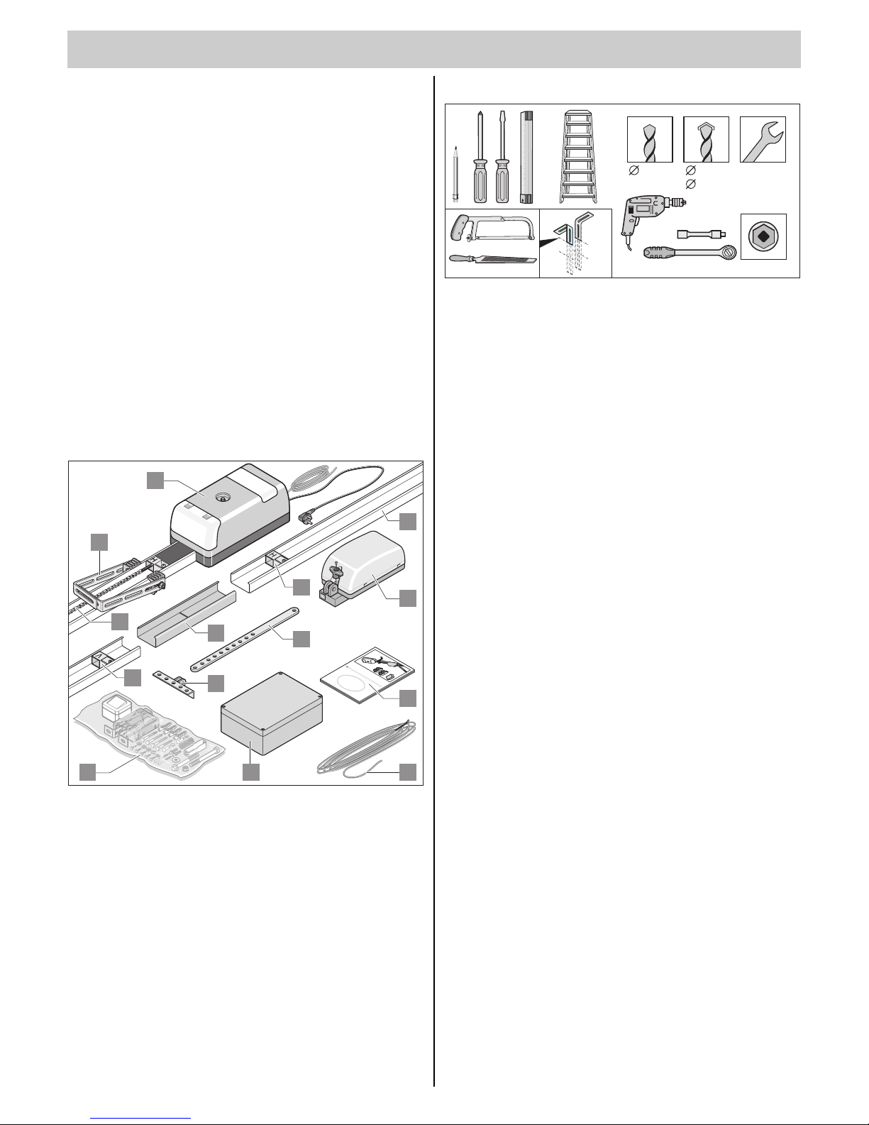
Required Tools
5mm 6mm
10mm
10mm
13mm
10mm
17mm2x
Safety Instructions
• The power cable supplied as standard may neither be shortened nor
lengthened.
• The power supply voltage must correspond to that indicated on the
operator’s rating plate.
• All devices requiring external connection must be equipped with safe
contact separation as per IEC 364-4-41, in order to isolate them from the
mains voltage supply.
• Live parts of the operator (voltage-carrying parts e.g. C-rails) may not be
connected to earth or to the live parts, or to protective conductors of
other circuits.
• IEC 364-4-41 must be observed when laying the external device conduc-
tors.
Installing the Slip-door Safety
Mechanism or Release Lock
• If your garage door is fitted with a slip door but not with a slip-door safety
mechanism, then you need to have one installed (see “Accessories”).
• If your door does not have a slip-door and your garage does not have a
separate entrance, then install a release lock or Bowden cable for operator release from the outside (see “Accessories” instructions).
Scope of Supply
• The scope of supply can vary according to the type of operator supplied.
1. 1 x control unit housing (with button line and power cord)
2. 1 x trolley
3. 2x C-rails
4. 1 x connecting piece
5. 1x switch trigger “H”
6. 1x switch trigger “V”
7. 1x chain
8. 1x connecting rod
9. 1x door hinge
10. 1x ceiling suspension bracket (for marathon tiga 1100 SL 2 units)
11. 1x Installation and Operating Instructions
12. 1x assembly kit
13. 1x signal light control unit
14. 1x signal line (7m)
M
o
n
t
a
g
e
u
n
d
B
e
t
r
i
e
b
s
s
a
n
l
e
i
t
u
n
g
1
3
0
D
D
EBS-II550SL, 800 SL, 1100 SL
1
10
7
3
2
11
1412 13
4
5
6
8
9
Preparations for Installation
5
6
Assembly
Safety Instructions
• Installation, connection and initial operation of the operator may only be
carried out by qualified specialists.
• Do not operate the door if people, animals or objects are in its range of
travel.
• Keep children, disabled persons, and animals away from the door.
• Safety goggles should be worn when drilling the mounting holes.
• Cover the operator when drilling to ensure that no grime penetrates the
unit.
The walls and ceiling must be firm and stable. Only fit the operator to a correctly aligned door. A door that has not been aligned
correctly can cause serious injuries.
• Doors must be stable because they are subjected to high traction and
pressure forces. Light doors made of plastic or aluminium must be reinforced before installation if necessary. Ask your dealer for advice.
• Remove door locking system or disable same.
• Only use approved fixing material (e.g. plugs, screws). The fixing materials must be suitable to the wall and ceiling material.
• Check that the door runs easily.
• The door must be balanced.
Test: Manually open the door half-way. The door must remain in this
position. If the door moves downward or upward, then mechanically readjust it. Ask your dealer for advice.
• Check the clearance between the door’s highest up-position (DHP, see
fig. 7) and the ceiling. The minimum clearance is 35 mm and the maximum clearance is 100 mm; the push arm can be at a max angle of 30°. If
clearance is less than that specified, then the operator must be shifted
towards the rear and an extended operator rail must be fitted. Ask your
local dealer for advice.
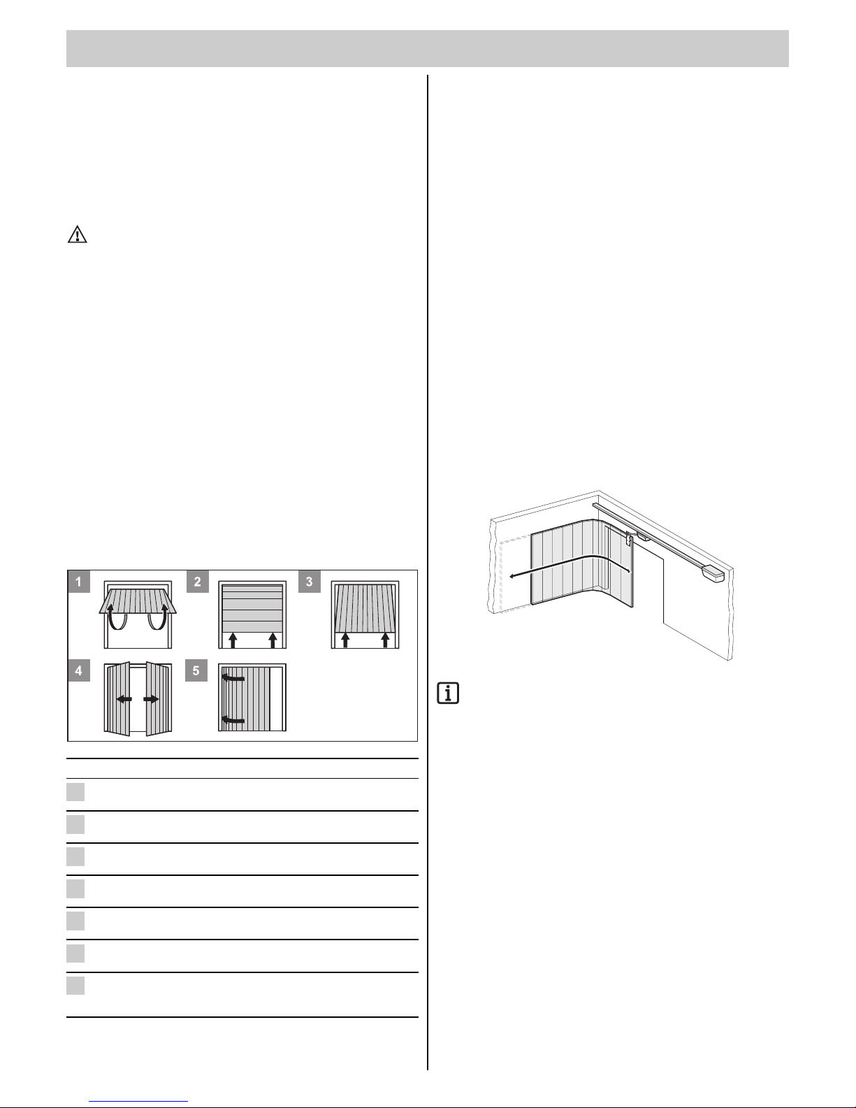
Door Types and Special Accessories*
* Accessories are not included in the delivery specification.
Door type Accessories
Swing door No special accessories required
Sectional door with single Sectional door fitting with
guide rail boomerang *
Vertical sectional door with Sectional door fitting without
double guide rail boomerang *
Rolling shutter door No special accessories required
Up-and-over door Tilting arm *
Wing door Wing-door fitting *
Side-opening sectional door Side opening sectional
door fittings*
Please consult your dealer
5
4
3
2
2
2
1
Installation Tips
• Check that all the parts have been supplied before you start installation
work in order to save time and unnecessary work if a part is missing.
• Installation work can be carried out quickly and reliably by two people.
• The operator can be installed to one side of the door if it cannot be
installed at the centre. In this regard, you must ensure that the door does
not bend and thus jam in the guide rails.
Test: Open and close the door several times by hand, holding it at the
point where you intend fitting the operator. If the door can be
moved at this point without difficulty (in compliance with the
prescribed forces), then the operator can be fitted.
• Emergency Release:
If the garage has no separate entrance (e.g. slip-door), the user must be
able to operate the emergency release mechanism from the outside.
Consequently route the emergency release to the outside. This can be
done with a Bowden cable or an emergency release lock. The backjump
(DIP switch 6 ON) should always be activated in this process.
• Swing doors
As the mechanical lock of a door with an operator must be dismantled or
deactivated, it is possible to open the door manually up to app. 50mm
depending on the door design.
To counter this situation, spring latches can be installed that lock the
door, in addition to the operator. These spring latches are connected to
the operator via a locking set in order to first unlock the spring latches
before the operator opens the door. Ask your dealer for advice.
• Wing door / side-opening sectional door:
For operators that push open a door of the above-mentioned type (see
Fig.):
- the polarity of wires 12 +13 must be swapped in the terminal bar.
Other pulse generators include: Remote control transmitters,
funkcody, radio-operated interior switches and key-operated
buttons. No connection line to the operator needs to be installed
for radio transmission, ask your dealer.
Installation
7
1
4
7
P
2
5
8
0
M
3
6
9
E
sc
0
1
2
1
4
7
P
2
5
8
0
M
3
6
9
Esc
8
2.1
4
6
4 x 0,75 mm
2
3 x 0,75 mm
2
3 x 1,5 mm
2
3 x 1,5 mm
2
3 x 1,5 mm
2
3 x 1,5 mm
2
3
5
2 x 0,75 mm
2
1.2
0
1
2
7
8
1.1
9
10
3
2 (4) x 0,75 mm
2
2 x 0,75 mm
2
2.2
9
Installation Tips
• Determine the mounting points for the operator and the signal light
control unit together with the operator.
• Determine the mounting point of the signal lights and additional
accessories together with the operator.
• Do not install the housing where it can be seen from the street, otherwise
passersby could damage the control unit.
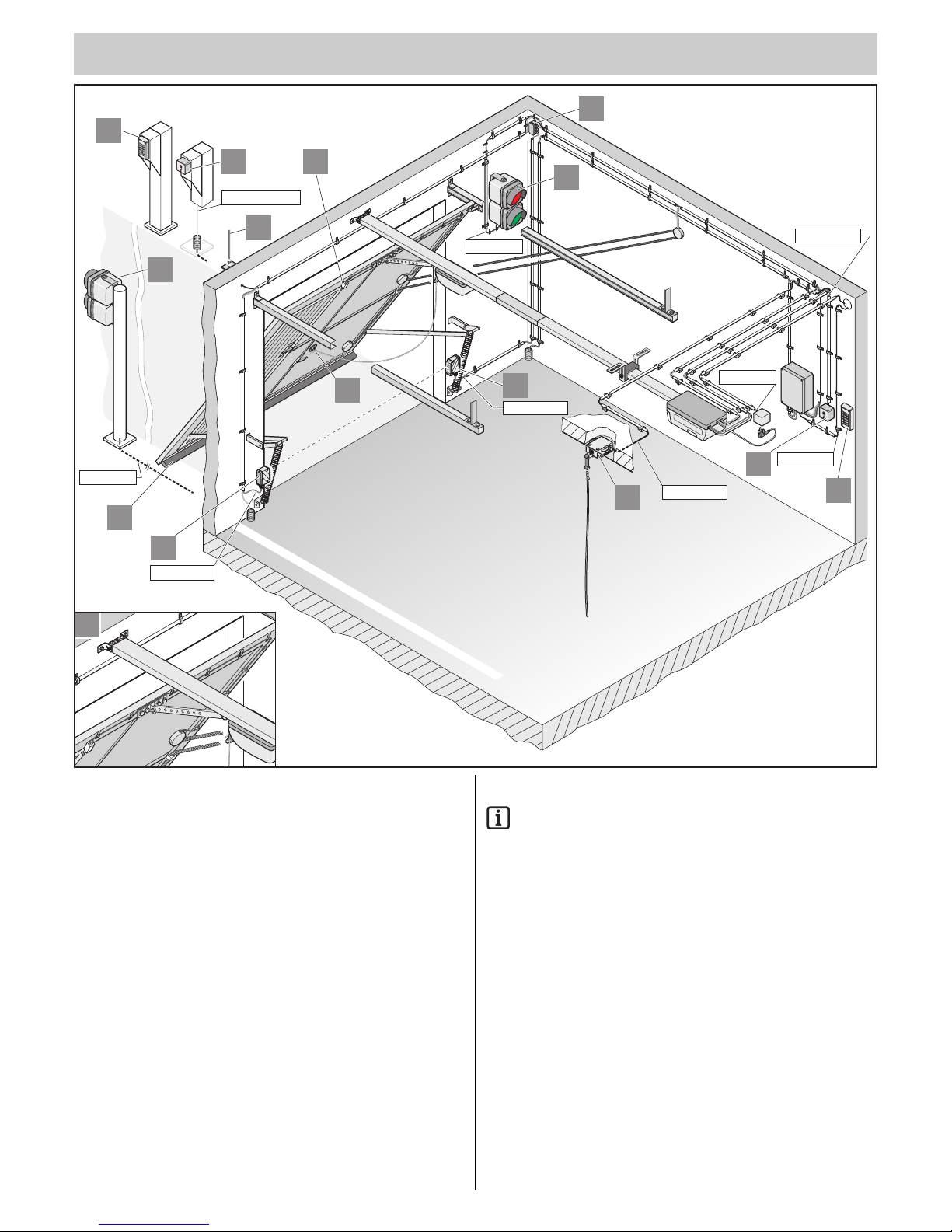
Accessories
Other pulse generators include: Remote control transmitters,
funkcody, radio-operated interior switches and key-operated
buttons. No connection line to the operator needs to be installed
for radio transmission, ask your dealer if you have questions.
1.1 Red / green signal light: Outside
1.2 Red / green signal light: Inside
2.1 Key-operated button, outside
2.2 Key-operated button, inside
3. Photoelectric cell
4. Junction box
5. Flagpole aerial (incl. 6 m, 10 m or 16 m cable)
6. Release lock
7. Pull-cord switch
8. Funkcody
9. Slip-door safety mechanism
10. Safety contact strip: 8.2 k Ohm or Fraba
Additional accessories on request.
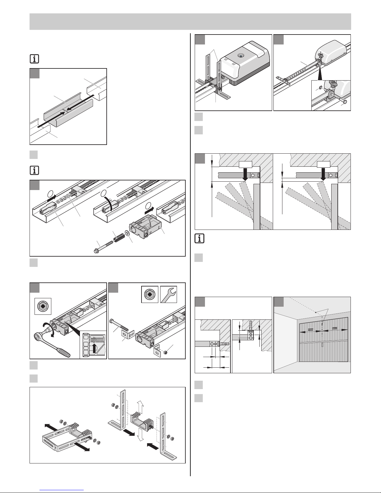
8
• Unscrew two steel angle irons with length adjustment holes (1) and
screw them onto ceiling bracket (2) as shown.
• Dismantle connecting rod (1):
Pull out retainer and remove bolt (3).
Installing the Operator
If the distance between the ceiling and the lower edge of the
C-rail is greater than 245 mm, then extend the suspension
bracket (with perforated steel strip).
• Determine door’s highest up-position (DHP): Open door and
measure smallest clearance (min. 35 mm) between top edge of door
and ceiling. The clearance between the highest up-position and the
bottom edge of the C-rails must be a min. of 5 mm and it may be a
max. of 65 mm; the push arm must be at a max. angle of 30°(for
swing doors) (see Fig. 17)!
• The operator can be mounted on the lintel (S) or ceiling (D).
• Measure front centre point (VM) of door and mark on door and on
lintel or ceiling.
9
8
8
VM
S
30
30
15
15
D
9
7
7
min. 35mm
THP
5 - 65mm
THP
6
5
65
2
1
2
3
1
Operator Pre-installation
• Remove the operator from its packaging.
Dispose of the packaging correctly in accordance with local
requirements.
• Slot two C-rails (1) into the connecting element (2) and push together
as far as they will go.
Note the uncoated inner side of the C-rails, this side must always
be facing the chain.
• Hook tensioner (1) in chain (2) and turn it 90°.
Insert connecting element (6) and push tensioner (1) through it.
Place plain washer (5) and spring (4) onto the tensioning bolt (3) and
screw it into the tensioner (1).
• Tighten chain until the mark (arrow) is reached.
• Mount bracket (2) with screw (1) and nut (3) on the connecting element (4).
4
3
3 4
17mm 17mm
10mm
V
1
2
3
V
2
2
a
c
90°
b
1
2
3
4
5
6
V
V
1
1
1
1
2
Installation
Assembly
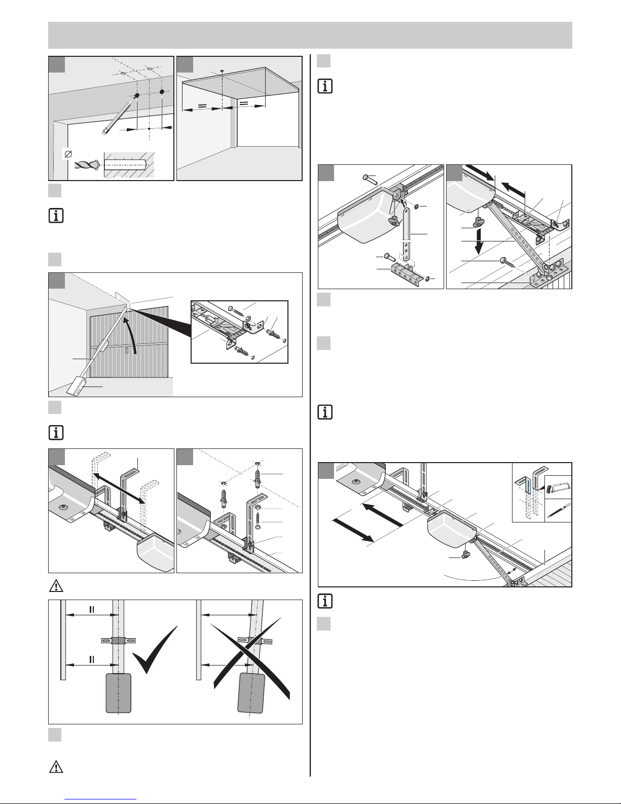
9
• Mark points 74 mm to right and left of the centre of door (VM), and at
same height on lintel or ceiling (see Fig. 8).
Wear safety goggles when drilling!
Check thickness of ceiling, particularly in the case of prefabricated garages!
• Drill two holes (Ø 10 x 65 mm).
• Open door. Transfer door centre mark (HM) to ceiling.
Close door.
• Insert plug (1). Lift up operator (2) at front. Secure lintel fitting (3) at
the front with two screws (4) and plain washers (5).
Protect control unit housing (6) from damage!
Attention !!
Always install operator parallel to the guide rails of the door.
• Lift up operator.
• Align ceiling bracket (1). It should be located within a range of
(R = 0 ...600 mm).
Use a non-slip, stable stepladder!
13
HM
14
B
600
0
1
1
HM
3
2
5
4
13
12
2
6
S10
4
5
31
12
11
10
VM
74mm 74mm
10mm
65mm
HM
10 11
• Align operator mechanism horizontally to rear centre of door (HM).
Mark position of holes.
Wear safety goggles when drilling!
Check thickness of ceiling, particularly in the case of prefabricated garages!
• Drill two holes (Ø 10 x 65 mm).
• Insert plug (1). Fit two screws (2) with plain washers (3). Tighten
screws (2) securely.
• Align C-rail (4) at correct height. If necessary, move screws (5).
Tighten screws (5).
• Mount connecting rod (1):
Introduce bolt (2) and attach the retainer (3).
• Mount door fitting (4)
insert bolt (5) and attach retainer (3).
• Pull once on the emergency release cord (N). This unlocks the trolley
(1). Tighten screw (8) on lintel fitting.
• Use connecting rod (2) to push trolley (1) as far forward as possible
(3). If necessary, release switch-trigger (4).
• Align angle of door fitting with centre of door (VM) and mark 5 drill
holes. Drill 5 holes (Ø 5 mm).
Wear safety goggles when drilling!
Use screws that are suitable for the door material.
• Insert 5 hexagon-head screws (6) and tighten securely.
• Release switch-trigger (4) and push right up to trolley (7).
• Tighten switch-trigger buffer screw (4) securely.
Trim (e.g. saw off and debur) projecting part of ceiling bracket (4).
• Release rear switch-trigger buffer (1) and push right back to stop (2).
Open door (3) by hand.
• Push switch-trigger (1) right up to trolley (5). Securely tighten screw
on switch-trigger (1).
17
4
7
N
1
8
2
6
max. 30°
4
5
3
17
16
15
15
2
3
5
4
3
1
2
48
7
3
6
5
1
N
VM
16
14
Assembly
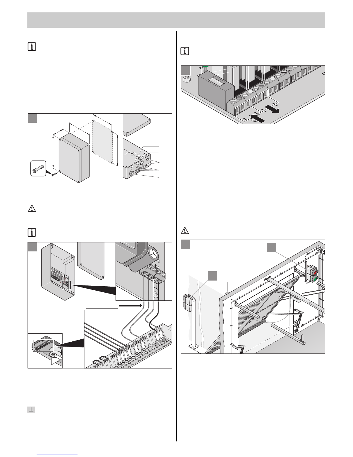
10
Mounting the control unit
Connect to mains voltage according to EN 12453 (all-pole
separating fixture)
• Work on the control unit may only be executed if it is de-energised.
• Dry any moisture that has penetrated with a blower.
• Only qualified electricians may connect the control unit to the mains
supply.
• Always install the control unit housing vertically, with the cable channels
downward, without deformation of the housing, so that water cannot penetrate and so that the lid forms a watertight seal.
• Only attach the housing using the intended fixing points, do not drill
through the rear wall of the housing. The housing will leak.
Connect the signal light control unit to the operator
Attention!
Always lay the cable separately from the house installation. Otherwise it is possible that the house installation can influence the
function of the signal light control unit.
Permissible cable cross-sections for all terminals:
0.5 mm
2
...1.5 mm2.
Signal light control unit Control unit Operator Cable colour
Terminal Terminal
SIG 0 -> 17 grey
SIG 1 -> 19 red
SIG 2 -> 24 blue
-> 23 black
19
2
3
4
5
6
7
8
9
10
11
12
13
14
15
16
17
18
19
20
21
22
23
24
1
L
L
N
N N
N
NGARI
RA
Licht
S
IG
0
S
IG
1
S
IG
2
N
GI
PE
PE
FUSE
5x20
5x20
9
10
11
12
13
14
15
16
17
18
19
20
21
22
23
24
12
14
17
13
15
19
24
23
SIG 0
SIG 1
SIG 2
4 x 0,5 ...1,5 mm
2
18
190
165
4x
254
90
M16
M20
M16
M16
M20
180
Connecting the signal light control unit to the mains
supply
Permissible cable cross-sections for all terminals:
1 mm
2
...2.5 mm2.
Description from left to right
Signal light control unit Mains supply: Input
Terminal
L -> AC 220 ...240 V
N -> Neutral conductor
PE -> Protective earth
Signal light control unit Mains supply: Voltage tap mains power
Terminal
PE -> Protective earth
N -> Neutral conductor
L -> AC 220 ...240 V
Signal light: Installation + connection
Please note!
Connect all signal lights to the signal light controller.
21
B
A
L
L
N
N
NN N
GA
RI
RA Lic
ht
NGI
PE PE
FUSE
5x20
20
 Loading...