

Marathon RJ-100SC, RJ-88SC, RJ-250SC, RJ-250VL User Manual

PLAY IT SAFE!
OPERATIONAL, MAINTENANCE,
AND INSTALLATION MANUAL
FOR
RJ-88SC
RJ-100SC
RJ-250SC
RJ-250VL
Includes HT (Hydraulic Tailgate) Units and SL
(StreamLine, Liquid Removal) Units
RAM-JET SELF-CONTAINED
COMPACTOR CONTAINER
VERNON, AL • FAYETTE, AL
YERINGTON, NV • CLEARFIELD, PA
Marathon Equipment Company • OMI Manual No. 0018, Rev. 9/03

CONTENTS
SECTION 1 - Operation
Introduction ..................................................................................................1-1
Specifications ............................................................................................... 1-2
Pre-Operation Instructions ....................................................................... 1-3
Operator Station .......................................................................................... 1-4
Operating Instructions For RJ-88SC, RJ-100SC, or RJ-250SC .................. 1-5
Operating Instructions For RJ-250VL .......................................................... 1-6
Optional Controls ......................................................................................... 1-7
Decals for RJ-88SC, RJ-100SC, RJ-250SC, or RJ-250VL ..........................1-8
Decal Placement for RJ-88SC, RJ-100SC, RJ-250SC, or RJ-250VL ......... 1-9
Additional Decals and Decal Placement for Hydraulic Tailgate (HT) Units . 1-11
SECTION 2 - Maintenance
Lock-Out & Tag-Out Instructions ............................................................. 2-1
Periodic Maintenance .................................................................................. 2-2
Procedures (Hydraulic System Pressure Check) ........................................ 2-3
Procedures (Ram Control Timer Adjustment) ............................................. 2-4
Procedures (Cylinder Removal, Multi Cycle Timer Adjustment) .................. 2-5
Principles of Operation ................................................................................ 2-6
Tailgate Seal Replacement .......................................................................... 2-7
Charts .......................................................................................................... 2-8
Parts List ...................................................................................................... 2-10
Motor Control Panel .................................................................................... 2-11
Power Unit - Standard 5 HP......................................................................... 2-12
Power Unit - Standard 10 HP........................................................................ 2-13
Hydraulic Schematic - Typical ......................................................................2-14
Trouble-shooting Chart ................................................................................ 2-15
SECTION 3 - Installation
Concrete Pad Requirements ....................................................................... 3-1
Steel Installation Procedures ....................................................................... 3-2
Electrical & Hydraulic Installation ................................................................ 3-3
Through-The-Wall Power Unit Installation ................................................... 3-5
SECTION 4 - Hauler Information
Hauler Instructions - General ....................................................................... 4-1
Hauler Instructions - Door/Latch Operation ..................................................4-2
Hauler Instructions - Hydraulic Tailgate Operation (for optional HT units) ... 4-3
Hauler Instructions - TailGate Manitenance Bar (for optional HT units)........ 4-4
Hauler Instructions - Liquid Removal (for optional SL units) ........................ 4-5
© Copyright March 2002, Marathon Equipment Co.

1 OPERATION
INTRODUCTION 1-1
THANK YOU FOR PURCHASING A MARATHON SELF-CONTAINED
COMPACTOR/CONTAINER.
This product is designed to give you reliable service and superior performance for years
to come. To guarantee top performance and the safest operation of the compactor, each
person involved in the operation, maintenance, and installation of the compactor should
read and thoroughly understand the instructions in this manual and follow all warnings.
The employer involved in the operation, maintenance, and installation of the self-contained compactor/container should read and understand the most current version of the
following applicable standards:
ANSI Standard No. Z245.2, “Stationary Compactors Safety Requirements”
A copy of this standard may be obtained from:
ENVIRONMENTAL INDUSTRIES ASSOCIATION
4301 Connecticut Avenue, NW Suite 300
Washington D.C. 20008
OSHA 29 CFR, Part 1910.147, “The control of hazardous energy (lockout/tagout)”
Any service or repairs that go beyond the scope of this manual should be
performed by factory authorized personnel only.
IF YOU SHOULD NEED FURTHER ASSISTANCE, PLEASE CONTACT YOUR
DISTRIBUTOR. YOU WILL NEED TO PROVIDE THE COMPACTOR SERIAL
NUMBER, INSTALLATION DATE, AND ELECTRICAL SCHEMATIC NUMBER
TO YOUR DISTRIBUTOR.
IF YOU HAVE ANY SAFETY CONCERNS WITH THE EQUIPMENT, OR
NEED FURTHER INFORMATION, PLEASE CONTACT US AT:
Marathon Equipment Company
P.O. Box 1798
Vernon, Al 35592-1798
Attn: Field Service Department
1-800-633-8974
1 OPERATION
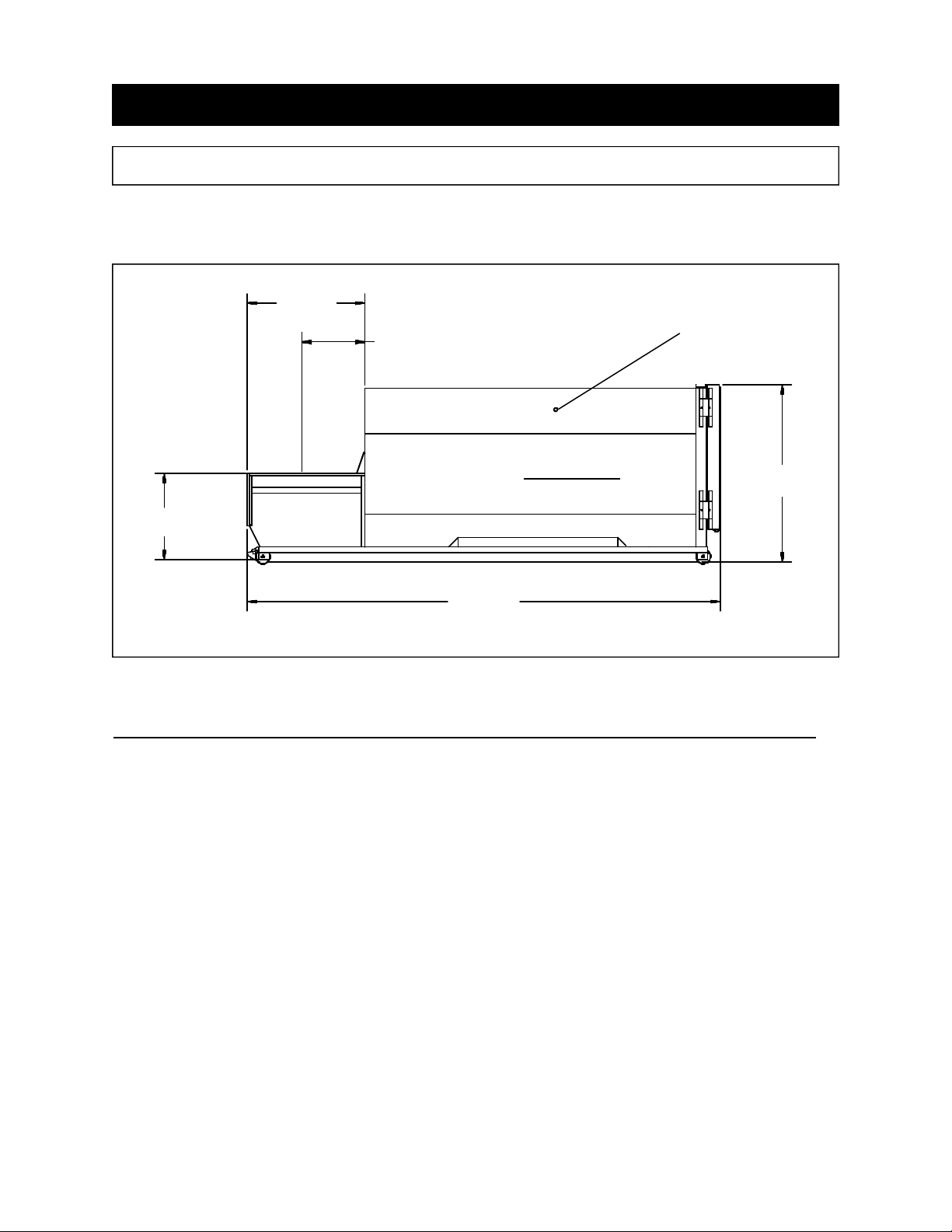
SPECIFICATIONS 1-2
“B”
“A”, Clear Top Opening
SIDE VIEW
COMPACTOR CONTAINER
“C”
“E”
Model
88SC 100SC 250SC 250VL
“A”, Clear Top Opening 30 1/2 x 48 35 x 60 40.5 x 58 35 x 60
(L x W)
Fire Port Each Side
“D”
“B” 70 76 1/8 68 76 1/2
“C” 42 49 5/8 52 1/2 51 1/2
“D” (max.) 96* 104* 104* 104*
“E” (max.) 254 1/2* 276* 275* 288*
Charge Box Capacity 1.00 1.50 1.90 1.90
(cubic yards)
WASTEC .70 1.32 1.53 1.53
Cycle Time (sec) 44 37 33 37
* Determined by the size and capacity of the container.
1 OPERATION
PRE-OPERATION INSTRUCTIONS 1-3
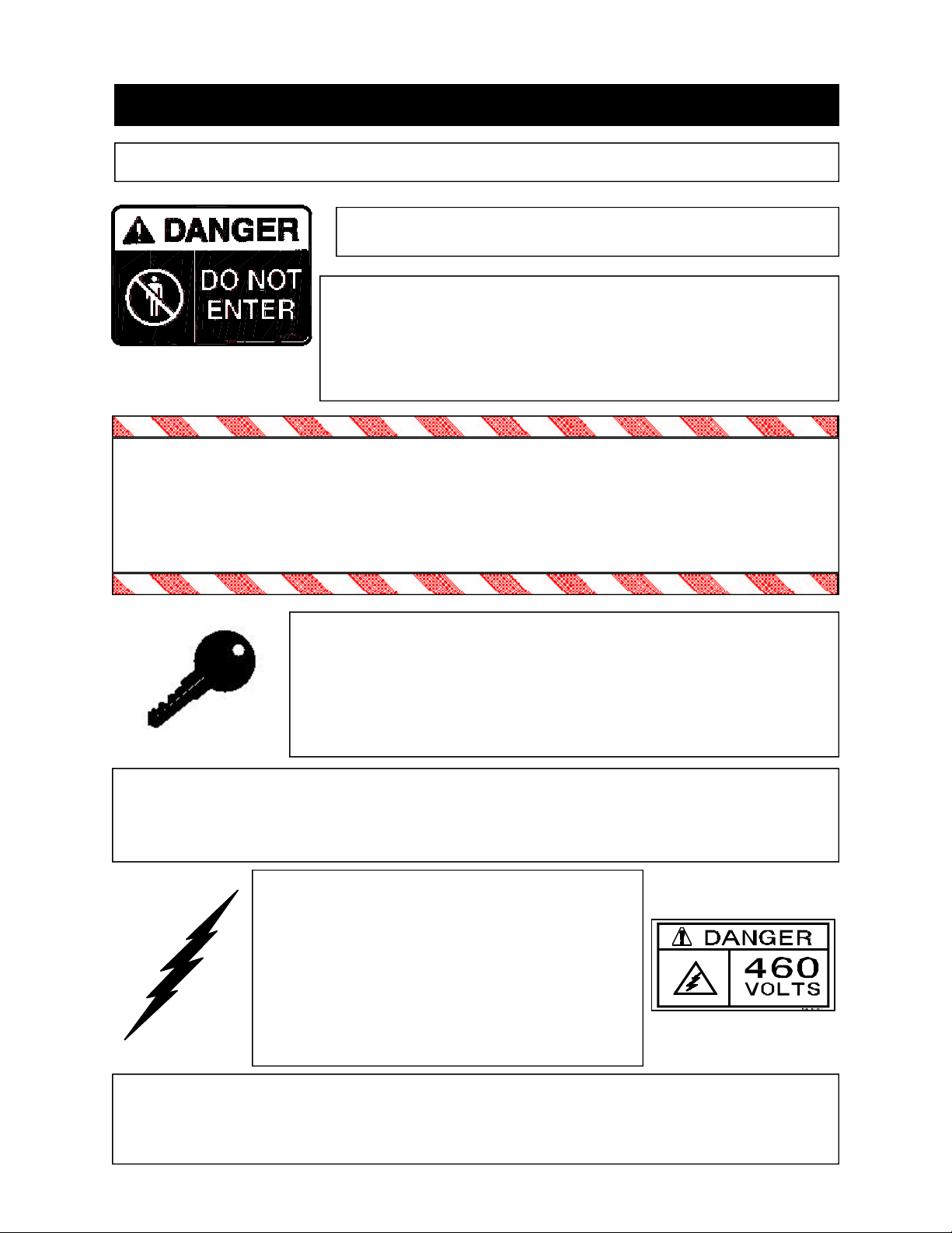
FEDERAL REGULATION PROHIBITS THE USE OF THIS
EQUIPMENT BY ANYONE UNDER 18 YEARS OF AGE.
STAY CLEAR OF ALL INTERNAL PARTS OF THE
SELF-CONTAINED COMPACTOR/CONTAINER
DURING OPERATION. FAILURE TO DO SO
COULD RESULT IN SERIOUS INJURY OR DEATH!
NEVER ENTER ANY PART OF THE COMPACTOR UNLESS THE DISCONNECT SWITCH HAS BEEN LOCKED-OUT AND TAGGED-OUT. See LockOut & Tag-Out instructions in the Maintenance section.
Before starting the
compactor, be sure no one is inside. Be certain that everyone is clear of all
points of operation and pinch point areas before starting.
THE EMPLOYER SHOULD ALLOW ONLY AUTHORIZED AND TRAINED PERSONNEL TO OPERATE
THIS COMPACTOR. This compactor is equipped with a
key operated locking system. The key(s) should be in
the possession of only authorized personnel.
DO NOT REMOVE ACCESS COVERS EXCEPT FOR SERVICING . Only authorized
service personnel should be allowed inside. All access doors on the compactor body
should always be secured in place when the unit is operating. See Lock-Out & Tag-
Out instructions in the Maintenance section.
ONLY AUTHORIZED PERSONNEL
SHOULD BE ALLOWED INSIDE THE
MOTOR CONTROL PANEL.
control panel contains high voltage components.
See Lock-Out & Tag-Out
The motor
Instructions in the Maintenance section.
If the compactor is equipped with a security gate or doghouse with security door, BE
SURE THAT THE SECURITY GATE OR DOOR IS CLOSED BEFORE THE COMPACTOR IS STARTED.
1 OPERATION
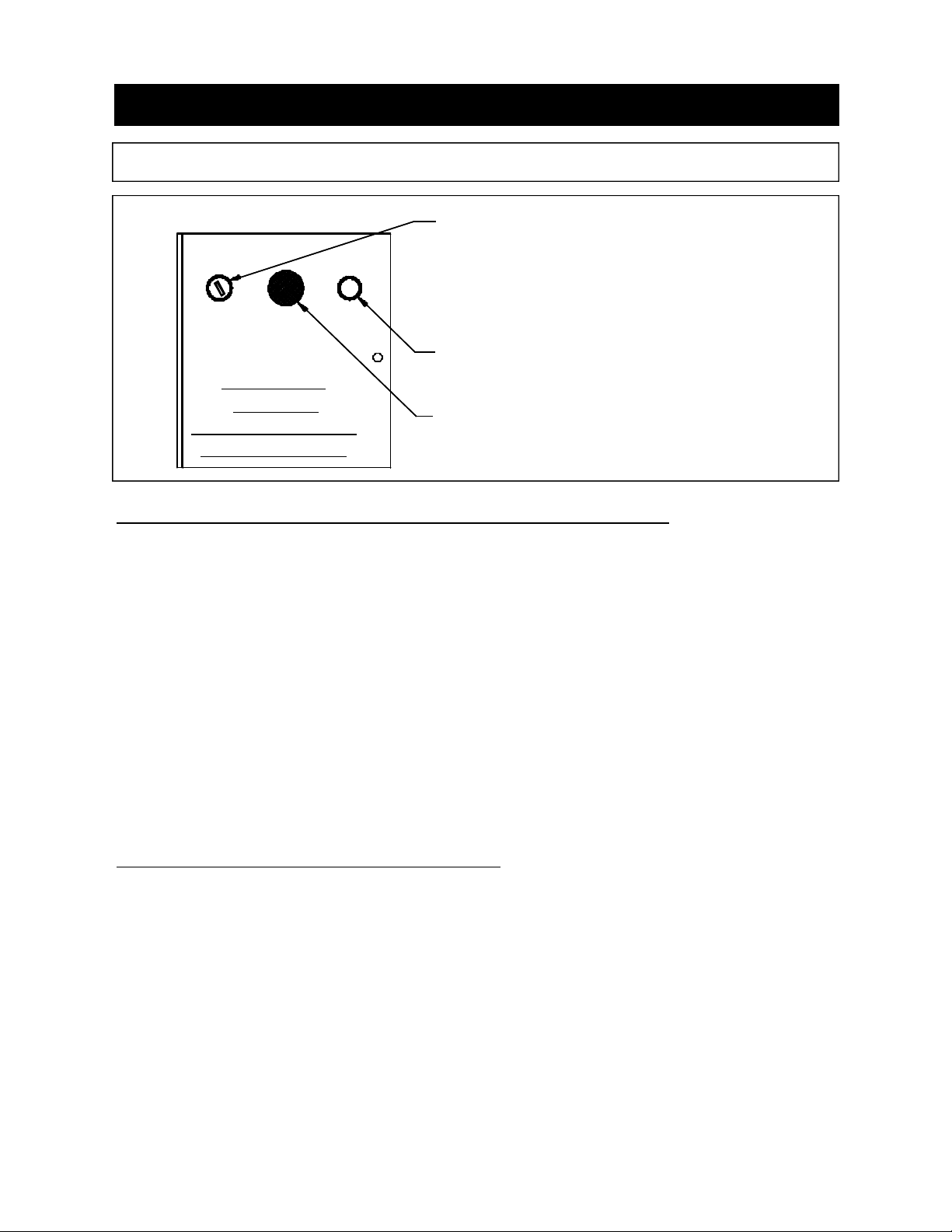
OPERATOR STATION 1-4
KEYED START SWITCH
REVERSE
OPERATOR
STATION
FOR 88SC, 100SC,
250SC, & 250 VL
CONTROL DESCRIPTION FOR 88SC, 100SC, & 250SC
KEYED START SWITCH - This switch requires a key for operation. Insert the key
1.
and turn clockwise to the start position. Depress and hold the key for one to two
seconds and release. The compactor will cycle one time (complete extension and
retraction of the ram) and stop. After use, turn the key to the counterclockwise
position and remove the key.
EMERGENCY STOP
2.
EMERGENCY STOP MUSHROOM HEAD PUSHBUTTON - When depressed, this
pushbutton will stop all powered operation of the compactor.
REVERSE PUSHBUTTON - This pushbutton will reverse the compaction ram
3.
when depressed. The Keyed Start Switch must be energized for the REVERSE
button to operate. See the MANUAL OVERRIDE INSTRUCTIONS on the next
page for details of the operation.
CONTROL DESCRIPTION FOR 250VL
KEYED START SWITCH - This spring-loaded switch requires a key for operation.
1.
Insert the key and turn clockwise to the start position and release. The compactor
will cycle one time (complete extension and retraction of the ram) and stop. After
use, remove the key.
EMERGENCY STOP MUSHROOM HEAD PUSHBUTTON - When depressed, this
2.
pushbutton will stop all powered operation of the compactor.
REVERSE PUSHBUTTON - This pushbutton will reverse the compaction ram
3.
when depressed. The Keyed Start Switch must be energized for the REVERSE
button to operate. See the MANUAL OVERRIDE INSTRUCTIONS on page 1-6 for
details of the operation.

1 OPERATION
OPERATING INSTRUCTIONS FOR RJ-88SC, RJ-100SC, & RJ-250SC
1-5
First, place the material to be discarded into the
1.
compactor.
Note: If you are loading the compactor through a door or
gate, close it before starting the compactor. Refer to
“Optional Loading Configurations” in the Decal Placement
section to determine how your compactor is set up.
Insert the key into the key switch. Turn it clockwise and depress for 1 to
2.
2 seconds and release. The unit will make one complete cycle, then
stop.
Repeat, if necessary, after the compactor has stopped.
3.
When you have finished using the compactor, remove the key from the
4.
key switch.
IN CASE OF EMERGENCY:
Push the large red button to STOP
MANUAL OVERRIDE INSTRUCTIONS (RAM STOP REAR ONLY - 88SC,
100SC, & 250SC)
If the ram is stopped in any position:
- To move the ram forward, turn the key switch clockwise and depress.
- To move the ram rearward, hold the reverse button down, turn and
depress the key switch, release the key switch, then release the
reverse button.
While the ram is moving:
- To reverse the ram while it is moving forward, press the reverse button.
- To cause the ram to move forward while it is moving rearward, depress
the key switch.
NOTE: Refer to Optional Controls for Manual Override on Ram Stop Forward Machines.
1 OPERATION
OPERATING INSTRUCTIONS FOR RJ-250VL 1-6
First, place the material to be discarded into the
1.
compactor.
Note: If you are loading the compactor through a door or
gate, close it before starting the compactor. Refer to
“Optional Loading Configurations” in the Decal Placement
section to determine how your compactor is set up.
Insert the key into the key switch. Turn it clockwise and release. The unit
2.
will make one complete cycle, then stop.
Repeat, if necessary, after the compactor has stopped.
3.
4.
When you have finished using the compactor, remove the key from the
key switch.
IN CASE OF EMERGENCY:
Push the large red button to STOP
MANUAL OVERRIDE INSTRUCTIONS (RAM STOP REAR ONLY - RJ-250VL)
If the ram is stopped in any position:
- To move the ram forward, turn the key switch clockwise and release.
- To move the ram rearward, hold the reverse button down, turn and
release the key switch, then release the reverse button.
While the ram is moving:
- To reverse the ram while it is moving forward, press the reverse button.
- To cause the ram to move forward while it is moving rearward, turn
and release the key switch.
NOTE: Refer to Optional Controls for Manual Override on Ram Stop Forward Machines.

1 OPERATION
OPTIONAL CONTROLS 1-7
SUSTAINED MANUAL PRESSURE CONTROL BUTTON (Hold-To-Run, Release-
1.
To-Stop) - This option requires the compactor operator to remain at the push button
station while the compactor is in use. Actuation requires depressing the "Hold-ToRun" and "Start" buttons. After the unit has started, the "Start" button is released. If
the "Hold-To-Run" button is released, the unit will stop instantly.
CONTAINER FULL LIGHT - When the light is on, the container is full and is ready to
2.
be emptied before its next use. To deactivate the light, depress the illuminated
emergency stop button. (The unit will not run while the light is on.)
ADVANCE WARNING LIGHT - When the light is on, the container is nearing the full
3.
level and a pick up call should be made. At this time 200 PSI is left before the pressure switch is activated to shut the unit off and container is full. (Unit will run with
light on.)
RAM STOP FORWARD - When a machine with this option has been stopped, the
4.
ram automatically begins to move rearward when restarted.
For the RJ-88SC, RJ-100SC, or RJ-250SC, to move the ram forward (when it is
stopped), hold the FORWARD button down, turn the key switch clockwise, depress
and release the key switch, then release the FORWARD button. To reverse the ram
while it is moving forward, depress the key switch. To cause the ram to move forward while it is moving rearward, press the FORWARD button.
For the RJ-250VL, to move the ram forward (when it is stopped), hold the FORWARD button down, turn and release the key switch, then release the FORWARD
button. To reverse the ram while it is moving forward, turn and release the key
switch. To cause the ram to move forward while it is moving rearward, press the
FORWARD button.
CYCLE TIMER - This option is used when more than one cycle is desired. The fac-
5.
tory setting is for three strokes (adjustable).
ACCESS INTERLOCK - This is optional with units equipped with doors, chutes, or
6.
access gates. It prevents the unit from operating while a door or gate is open.

1 OPERATION
DECALS for RJ-88SC, RJ-100SC, RJ-250SC, or RJ-250VL 1-8
WARNING DECAL REQUIREMENTS
When your compactor leaves the factory, several WARNING DECALS are installed for
protection. These labels are subject to wear and abuse due to the nature of the refuse
handling operation. THESE DECALS MUST BE MAINTAINED. Additional decals may
be purchased from your distributor or from Marathon Equipment Company.
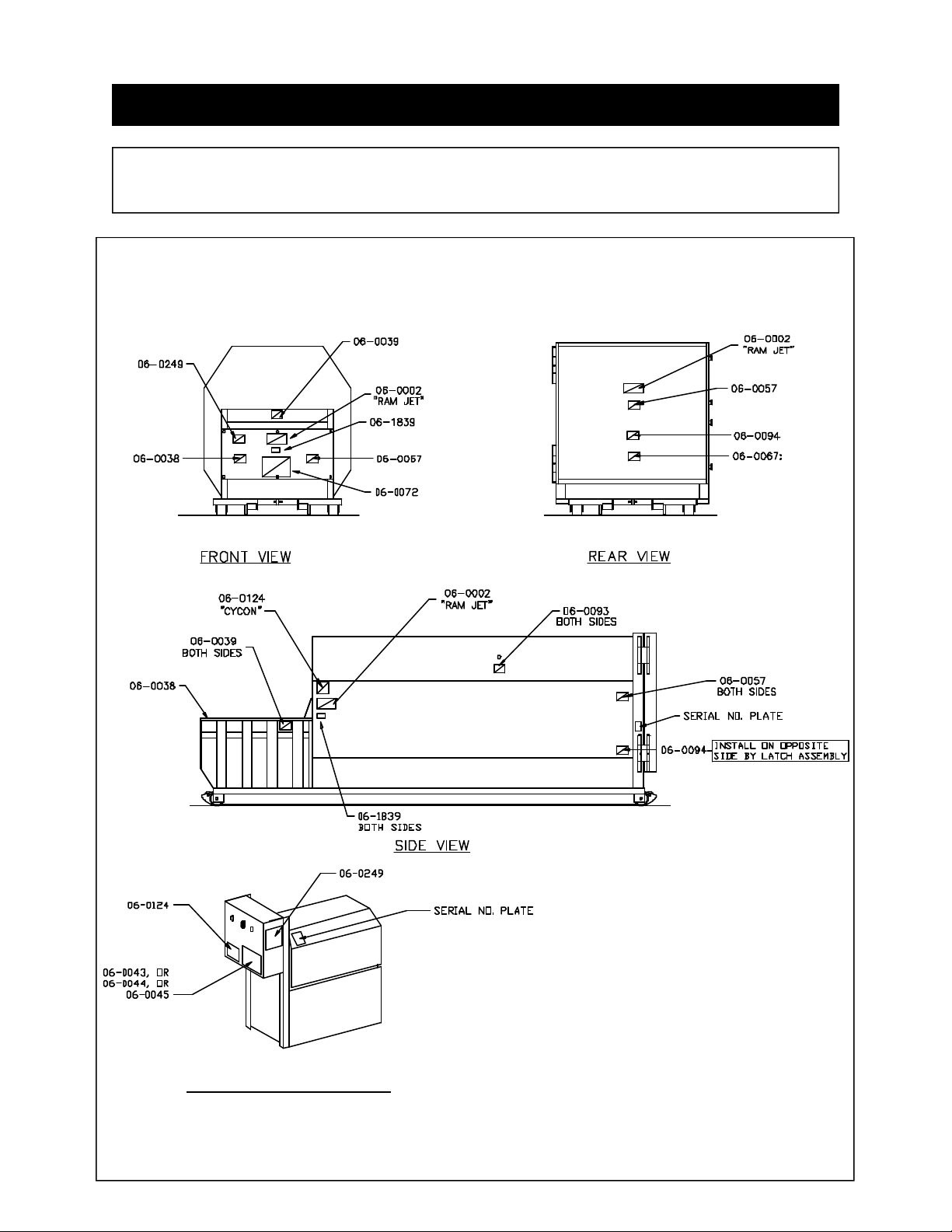
Decal Number 06-0002 Decal Number 06-0003 Decal Number 06-0011 Decal Number 06-0038 -
Decal Number 06-0039 Decal Number 06-0040 Decal Number 06-0043 Decal Number 06-0044 Decal Number 06-0045 Decal Number 06-0052 -
Decal Number 06-0057 Decal Number 06-0058 Decal Number 06-0059 -
RAM JET - MARATHON EQUIPMENT COMPANY
PATENT PENDING
MOTOR ROTATION
CAUTION: DO NOT REMOVE ACCESS COVER EXCEPT FOR SERVICING. FOLLOW
LOCK OUT- TAG OUT PROCEDURES.
DANGER: DO NOT ENTER.
CAUTION: KEEP OUT. (used on hoppers)
DANGER: 208 VOLTS, or
DANGER: 230 VOLTS, or
DANGER: 460 VOLTS.
CAUTION: GATE MUST BE CLOSED BEFORE OPERATING COMPACTOR. (used on
access gates)
CAUTION: STAND CLEAR WHEN CONTAINER IS BEING LIFTED.
‘A’ PORT
‘B’ PORT
Decal Number 06-0067 Decal Number 06-0072 Decal Number 06-0093 Decal Number 06-0094 Decal Number 06-0104 Decal Number 06-0105 Decal Number 06-0364 Decal Number 06-0121 -
Decal Number 06-0124 Decal Number 06-0249 Decal Number 06-1839 -
CAUTION: DO NOT REMOVE THIS CONTAINER UNTIL REAR STOP IS INSTALLED.
QUICK CLEAN TANK
FIRE HOSE PORT.
NOTICE: WIPE OFF SEAL AFTER DUMPING.
HYDRAULIC TAILGATE OPERATING INSTRUCTIONS
DANGER: STAND CLEAR OF TAILGATE WHEN LIFTED.
SERIAL NUMBER PLATE
FEDERAL REGULATIONS PROHIBITS THE USE BY PERSONS UNDER 18 YEARS OF
AGE.
CYCON
DANGER: HAZARDOUS VOLTAGE ... LOCK OUT & TAG OUT.
AMERICAN FLAG
1 OPERATION
DECAL PLACEMENT for RJ-88SC, RJ-100SC, RJ-250SC,
or RJ-250VL 1-9
REMOTE POWER UNIT
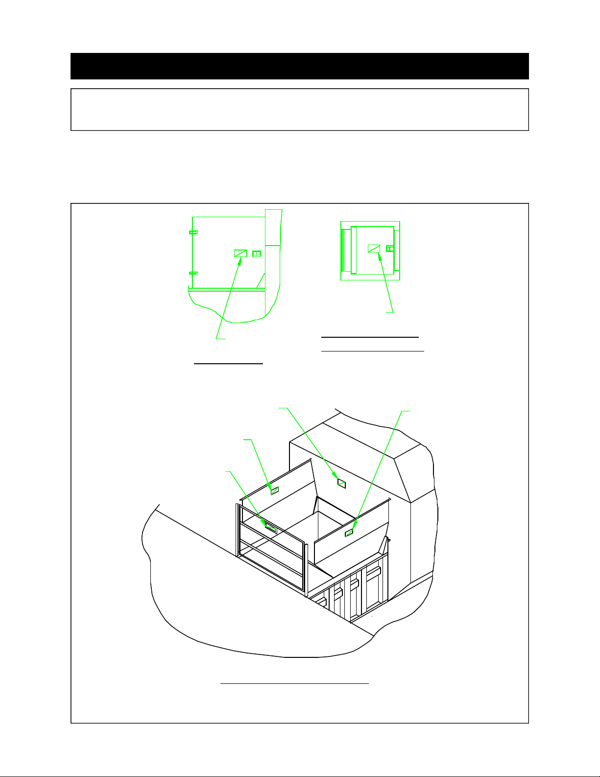
1 OPERATION
DECAL PLACEMENT for RJ-88SC, RJ-100SC, RJ-250SC,
or RJ-250VL 1-10
OPTIONAL LOADING CONFIGURATIONS
06-0039
06-0039
DOGHOUSE
06-0039
EACH INSIDE WALL
06-0039
06-0039,
06-0052
DOCK
THRU-THE-WALL
SECURITY CHUTE
06-0040
EACH OUTSIDE WALL
ACCESS GATE & HOPPER
 Loading...