

Page 1

Model WB6001T User Guide
Tilt Flat Wall Mount for 61” Plasma
Page 2
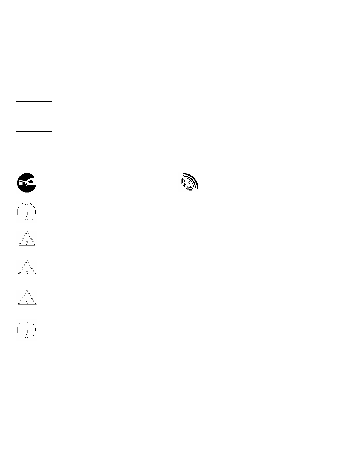
Warning Statements
WARNING:
WARNING:
WARNING:
THE WALL STRUCTURE MUST BE CAPABLE OF SUPPORTING 160 LBS. IF NOT,
THE WALL STRUCTURE MUST BE REINFORCED. PROPER INSTALLATION
PROCEDURE BY A QUALIFIED SERVICE TECHNICIAN, AS OUTLINED IN THE
INSTALLATION INSTRUCTIONS, MUST BE ADHERED TO. FAILURE TO DO SO
COULD RESULT IN SERIOUS PERSONAL INJURY, OR EVEN DEATH.
SAFETY MEASURES MUST BE PRACTICED AT ALL TIMES DURING THE
INSTALLATION OF THIS PRODUCT. USE PROPER SAFETY GEAR AND TOOLS
FOR THE INSTALLATION PROCEDURE TO PREVENT PERSONAL INJURY.
PRIOR TO THE INSTALLATION OF THIS PRODUCT, THE INSTALLATION
INSTRUCTIONS SHOULD BE READ AND COMPLETELY UNDERSTOOD. THE
INSTALLATION INSTRUCTIONS MUST BE READ TO PREVENT PERSONAL
INJURY AND PROPERTY DAMAGE. KEEP THESE INSTALLATION INSTRUCTIONS
IN AN EASILY ACCESSIBLE LOCATION FOR FUTURE REFERENCE.
Indicates that the power plug is to be
disconnected from the power outlet.
Safety precautions must be taken at
Contact Marantz with any questions -
(630)-741-0300.
all times.
Warning and Caution statements.
Do not install on a structure that is prone to vibration, movement or chance of impact.
Failure to do so could result in damage to the flat panel display and/or damage to the
mounting surface.
Do not install near heater, fireplace, direct sunlight, air conditioning or any other source of
direct heat energy. Failure to do so may result in damage to the flat panel display and could
increase the risk of fire.
At least two qualified people should perform the installation procedure. Injury and/or
damage can result from dropping or mishandling the flat panel display.
Page 3

Table of Contents
Warning Statements ..............................................................................................................................................- 2 -
1.0 PARTS LIST .............................................................................................................................................- 4 -
1.1 Installation Tools .....................................................................................................................................- 4 -
2.0 FINDING THE CENTER OF THE DISPLAY ...........................................................................................- 5 -
3.0 POSITIONING THE MOUNTING BRACKETS .......................................................................................- 6 -
4.0 SECURING THE MOUNTING BRACKETS ............................................................................................- 7 -
5.0 WOODEN STUD LOCATION ...................................................................................................................- 8 -
6.0 FLAT PANEL INSTALLATION .............................................................................................................- 12 -
7.0 LATERAL SHIFT ADJUSTMENT ..........................................................................................................- 12 -
8.0 TECHNICAL SPECIFICATIONS ............................................................................................................- 13 -
- 3 -
Page 4
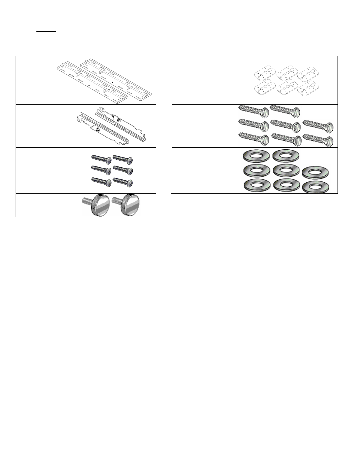
1.0 PARTS LIST
NOTE: This wall mount is shipped with all proper installation hardware and components. Make
sure that none of these parts are missing before beginning installation. If there are parts
missing stop the installation and contact Marantz.
Wall plate
(Qty 2)
Universal
Mounting
Brackets
(Qty 2)
M8 x 20mm
Phillips Head
Screws (Qty 6)
M6 x 12mm
Safety Knobs
(Qty 2)
Griplates™ (Qty 6)
5/16” x 3” Lag Bolts
(wooden studs only)
(Qty 8)
5/16” Flat Washers
(Qty 8)
1.1 Installation Tools
Phillips Head Screw Driver Soft Material/ Blanket Pencil
Tape Measure Drill Gun
Level (Supplied) 5/16” Socket Wrench
- 4 -
Page 5
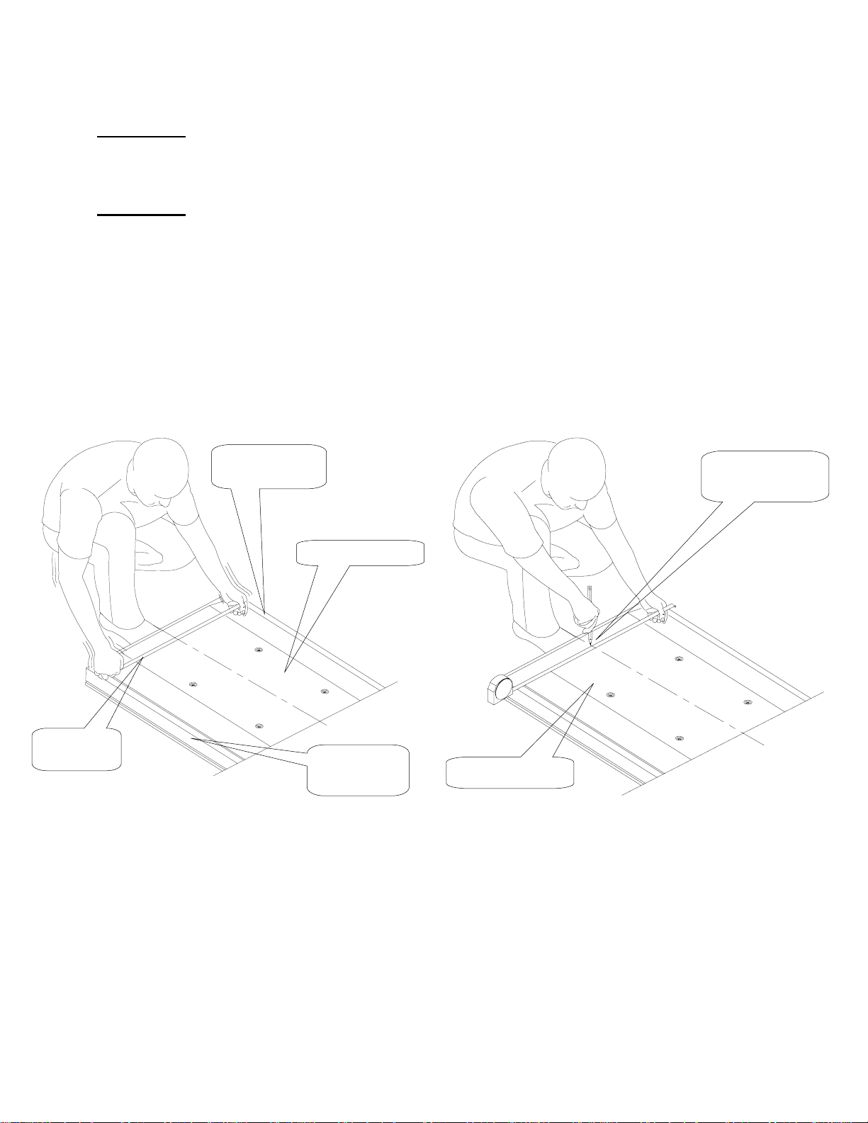
2.0 FINDING THE CENTER OF THE DISPLAY
WARNING:
Proper installation procedure by qualified personnel as outlined in the installation
instructions must be adhered to. Failure to do so could result in serious personal
injury and possible damage to the flat panel.
DO NOT LAY THE FLAT PANEL ON THE FLOOR DURING ANY STEP OF THE
WARNING:
INSTALLATION PROCESS.. THE FLAT PANEL IS HEAVY AND FRAGILE. AT
LEAST TWO QUALIFIED PERSONNEL ARE STRONGLY RECOMMENDED FOR
INSTALLATION OF THIS PRODUCT. FAILURE TO DO SO COULD RESULT IN
SERIOUS INJURY AND POSSIBLE DAMAGE TO THE FLAT PANEL
Step 1 Step 2
Use a measuring tape to find the center of your
flat panel measuring from outside to outside of
the flat panel (Figure 1).
Top of flat
panel
Using a pencil lightly mark the center of your flat
panel (Figure 2).
Mark the center of
the flat panel
Inverted flat panel
C
Measuring
tape
Figure 1
L
Bottom of flat
panel
C
L
Inverted flat panel
Figure 2
- 5 -
Page 6

F
F
F
F
F
3.0 POSITIONING THE MOUNTING BRACKETS
Step 3 Step 4
Lay the mounting brackets (stamped arrows
facing out) - (Figure 3).
Match the center of viewing guide with the
centerline you marked in Step 1 (Figure 4).
Inverted
lat Panel
Bottom of
lat Panel
Arrows
acing Out
Figure 3 Figure 4
Step 5
The mounting brackets are designed with a
center viewing guide on the side of them
(Figure 5).
Mounting
Brackets
Align the
Mounting
Brackets
C
L
Bottom of
the Flat
Bottom of
lat Panel
Center of
Viewing
Guide
Center of
lat Panel
Figure 5
- 6 -
Page 7

4.0 SECURING THE MOUNTING BRACKETS
Step 6 Step 7
The Griplates™ have M4, M5, M6 and M8 hole
patterns to fit the hardware that your flat panel
requires.
EXAMPLE: If your plasma uses M8 x 20 Phillip
screws. Use the M8 mounting points (Figure 6).
DIMPLES
M5 M4
M6
M8
Once the mounting brackets are aligned, secure
the Griplate™ to the flat panel.
NOTE
: The dimples of the top plates have to be
facing up and the bottom dimples must
be facing down. Use (1) Griplate™ per
mounting point (Figure 7).
Phillips screw driver
DIMPLES
FACING UP
DIMPLES
FACING UP
DIMPLES
FACING DOWN
DIMPLES
FACING DOWN
3/4"
Bottom of flat
panel
Figure 6
Figure 7
- 7 -
Page 8

5.0 WOODEN STUD LOCATION
Step 8 Step 9
Using a (commercially available) wood stud
finder, locate the 16" or 24" stud centers behind
the wall. Once found, make a pencil marking on
the center of the wood studs (Figure 8).
NOTE: The wall plates have (3) 16" and (1)
24" mounting slot positions.
Wood Stud Finder
(Commercially Available)
Mark the Wall
and the Center
of the Studs
Measure from the floor to the desired viewing
height and mark the wall.
NOTE
: This marking will reference the center of
your flat panel display once mounted on
the wall (Figure 9).
16"
16"
Measure and
mark the
viewing height
desired on the
wall.
Wooden Studs
Figure 8
Figure 9
- 8 -
Page 9

Step 10 Step 11
Place the bottom portion of the wall plate to the
reference line and mark the four (4) lag bolt
mounting points through the wall plate slots on
the wall (Figure 10).
16"
Wall Plate
Level the wall plate with the reference arrow
pointing up to the ceiling (Figure 11).
Mounting Surfaces
Wood studs: Drill four (4) ¼" pilot holes to the
marked wall.
Concrete wall: Drill four (4) 3/8” pilot holes to the
marked wall.
Drill Gun
Pilot Holes
16"
Mounting Slots
Level
Wooden Studs
Figure 10
Figure 11
- 9 -
Page 10

Step 12 – Wooden Stud Installation
Level and secure the lower plate to the wall with the reference arrow facing up to the ceiling.
Secure the plate using the four (4) 5/16" lag bolts and flat washers (supplied) – (Figure 12).
Repeat Step 5 to secure the upper wall plate to the wall (Figure 12).
CAUTION: Do not over tighten the lag bolts.
NOTE: Use a minimum diameter of 5/16” x 3” long wood screws
Wall Plate
Figure 12
- 10 -
Figure 13
Page 11

Step 13 – Concrete Installation
Level and secure the lower plate to the wall with the reference arrow facing up to the ceiling.
NOTE: Each hole must be drilled using a 7/16” drill bit.
Use a diameter of 3/8” x 2 ¼” large concrete wedge anchors (commercially available) – (Figure 14).
Gently tap the wedge anchor into the hole. When the wedge anchor cannot go any further. Place the wall
mount over the threaded studs of the wedge anchor and tighten each bolt.
CAUTION: Do not over tighten the wedge anchors bolts.
NOTE: Use a diameter of 3/8” x 2 ¼” long wedge anchors (commercially available).
Wall Plate
3/8” x 2 ¼” wedge
anchors (Commercially
Available)
Figure 14
- 11 -
Page 12

W
6.0 FLAT PANEL INSTALLATION
Step 14
WARNING: AT LEAST (2) QUALIFIED PERSONNEL ARE STRONGLY RECOMMENDED FOR
INSTALLATION OF THIS PRODUCT. FAILURE TO DO SO COULD RESULT IN
SERIOUS INJURY AND POSSIBLE DAMAGE TO THE FLAT PANEL.
Raise the flat panel with the mounting brackets secured to the flat panel and insert the top hooks
from each bracket to the rod from the wall plates (Figure 15).
all plate
TOP
BOTTOM
Figure 15
7.0 LATERAL SHIFT ADJUSTMENT
Step 15
Make any lateral shift adjustment and lock it by tightening the two (2) ¼”-20 Phillips screws found on
the bottom of the mounting brackets. Use the foot leveler to adjust your plasma.
CAUTION: Do not over tighten the ¼”-20 screws to the rods (Figure 16).
Lateral
shift
Figure 16
- 12 -
Page 13

A
8.0 TECHNICAL SPECIFICATIONS
Dimensions are in Inches and (mm)
H
28.000
(171.2)
16.000
(406.4)
C
L
1.245
(31.75)
A
B
5.000
(127)
19.000
12.000
(482.6)
(304.8)
. Wall plate
B. Mounting brackets
C. Griplate™
D. Mounting hardware
E. M6 x 30 (mm) Phillip screws
F. Wood stud
G. 5/16” x 3” Lag screws and flat washers
H. Safety knobs
21.000
10.500
(266.7)
5.000
(127)
(533.4)
C
L
C
G
16.000
F
(406.4)
16.000
(406.4)
(616.97)
24.290
16.000
(406.4)
D
E
2.331
(59.21)
G
H
1
20.500
(520.7)
2
1. M5 Phillips screws for fine tension
2. M8 Hex nut coarse tension
NOTE: The 8 (mm) hex nut is for your coarse
tension adjustment and the 5 (mm) screws are for
your fine tension adjustment.
Figure 17
- 13 -
Page 14

www.marantz.com
You can find your nearest authorized distributor or dealer on our website.
U.S.A.
- 14 -
Marantz America, Inc. 1100 Maplewood Drive, Itasca, IL 60143, U.S.A.
is a registered trademark.
 Loading...