

Marantz VS-3002 Service Manual
Service
VS3002
VS3002 /
E1B
Manual
SECTION PAGE
1. TECHNICAL SPECIFICATIONS ........................................................................................... 1
2. SERVICE MODE ................................................................................................................... 2
3. UPDATE FIRMWARE ............................................................................................................ 3
Install Procedure .............................................................................................................. 3
Update Procedure ............................................................................................................6
4. WIRING DIAGRAM ............................................................................................................. 11
5. BLOCK DIAGRAM .............................................................................................................. 13
6. SCHEMATIC DIAGRAM ...................................................................................................... 15
7. PARTS LOCATION .............................................................................................................. 29
8. EXPLODED VIEW AND PARTS LIST ................................................................................. 37
9. MICROPROCESSOR AND IC DATA .................................................................................. 40
10. ELECTRICAL PARTS LIST ................................................................................................. 45
11.
ABOUT REPLACE THE MICROPROCESSOR WITH A NEW ONE ...............................53
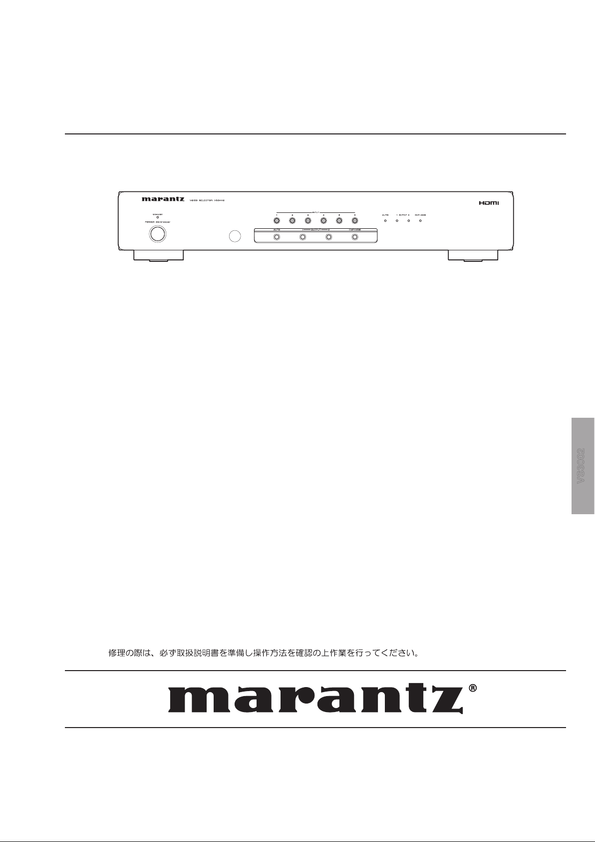
Video Selector
TABLE OF CONTENTS
Please use this service manual with referring to the user guide ( D.F.U. ) without fail.
VS3002
Part no. 90M30AV855012
First Issue 2008.01
MZ
MARANTZ DESIGN AND SERVICE
USA
MARANTZ AMERICA, INC
100 CORPORATE DRIVE
MAHWAH, NEW JERSEY 07430
USA
EUROPE / TRADING
MARANTZ EUROPE B.V.
P. O. BOX 8744, BUILDING SILVERPOINT
BEEMDSTRAAT 11, 5653 MA EINDHOVEN
THE NETHERLANDS
PHONE : +31 - 40 - 2507844
FAX : +31 - 40 - 2507860
KOREA
D&M SALES AND MARKETING KOREA LTD.
CHUNG JINB/D.,#1001,
53-5, WONHYORO3 GA,YONGSAN-GU,
SEOUL, 140-719, KOREA
PHONE : +82 - 2 - 323 - 2155
FAX : +82 - 2 - 323 - 2154
CANADA
D&M CANADA INC.
5-505 APPLE CREEK BLVD.
MARKHAM, ONTARIO L3R 5B1
CANADA
JAPAN
D&M BUILDING, 2-1 NISSHIN-CHO,
KAWASAKI-KU, KAWASAKI-SHI,
KANAGAWA, 210-8569 JAPAN
D&M Holdings Inc.
CHINA
MARANTZ SHANGHAI TRADING LTD.
ROOM.506SHANGHAILIGHTINDUSTRY MANSION
1578NANJING (WEST) ROAD SHANGHAI
CHINA
TEL : 021 - 6248 - 1064
FAX : 021 - 6248 - 3565
Using superior design and selected high grade components,
Only original
MARANTZ
parts can insure that your
MARANTZ
MARANTZ
product will continue to perform to the specifications for which
company has created the ultimate in stereo sound.
it is famous.
Parts for your
MARANTZ
ORDERING PARTS :
equipment are generally available to our National Marantz Subsidiary or Agent.
Parts can be ordered either by mail or by Fax.. In both cases, the correct part number has to be specified.
The following information must be supplied to eliminate delays in processing your order :
1. Complete address
2. Complete part numbers and quantities required
3. Description of parts
4. Model number for which part is required
5. Way of shipment
6. Signature : any order form or Fax. must be signed, otherwise such part order will be considered as null and void.
NOTE ON SAFETY :
Symbol Fire or electrical shock hazard. Only original parts should be used to replaced any part marked with symbol .
Any other component substitution (other than original type), may increase risk of fire or electrical shock hazard.
安全上の注意:
がついている部品は、安全上重要な部品です。必ず指定されている部品番号のものを使用して下さい。
SHOCK, FIRE HAZARD SERVICE TEST :
CAUTION : After servicing this appliance and prior to returning to customer, measure the resistance between either primary AC
cord connector pins ( with unit NOT connected to AC mains and its Power switch ON ), and the face or Front Panel of product
and controls and chassis bottom.
Any resistance measurement less than 1 Megohms should cause unit to be repaired or corrected before AC power is applied,
and verified before it is return to the user/customer.
Ref. UL Standard No. 1492.
In case of difficulties, do not hesitate to contact the Technical
Department at above mentioned address.
070719MZ
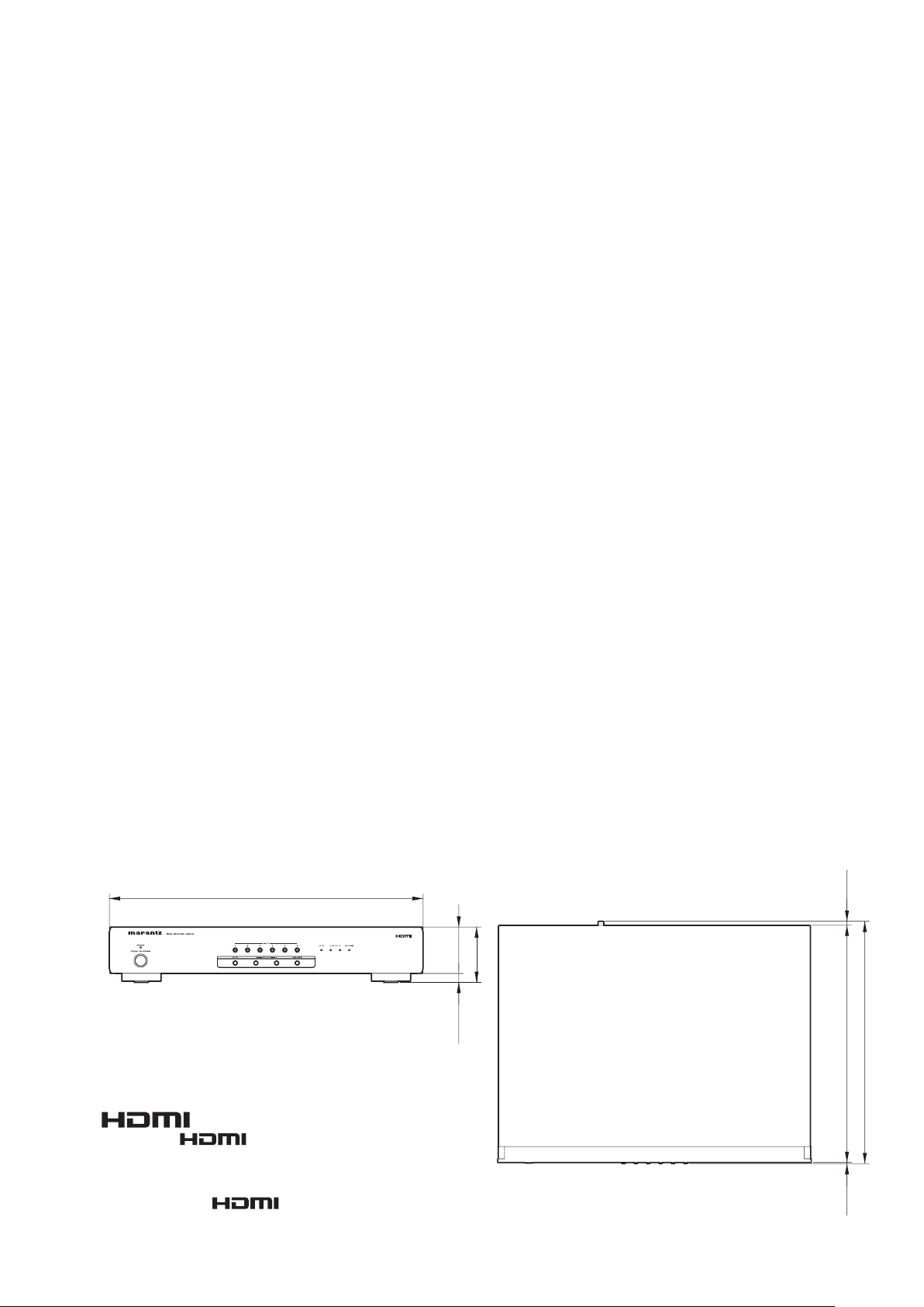
1. TECHNICAL SPECIFICATIONS
340 (13-7/16)
2 (1/8)
6 (1/4)
332 (13-1/8)
340 (13-7/16)
2 (1/8)
6 (1/4)
332 (13-1/8)
440 (17-3/8)
13 (9/16)
65
(2-9/16)
78 (3-1/8)
Electrical System
Input and output signals
HDMI INPUT ...................................................................6 jacks (Ver. 1.3b, single link only)
HDMI OUTPUT ...............................................................2 jacks (Ver. 1.3b, single link only)
REMOTE CONTROL IN ....................................................................................1 jack (RCA)
REMOTE CONTROL OUT ................................................................................1 jack (RCA)
FLASHER IN .....................................................................................1 jack (3.5 Ø mini jack)
Power requirement (U.S.A.) ..............................................................................AC 120V 60Hz
(Europe) ........................................................................AC 230V 50/60Hz
(Japan) ..........................................................................AC 100V 50/60Hz
Power consumption .....................................................................5 W / 0.8 W (during standby)
Others
Operating temperature and humidity ........... 5 to 35°C / 30 to 85% (no condensation allowed)
Storage temperature and humidity ............ 20 to 60°C / 30 to 85% (no condensation allowed)
Maximum External Dimensions (Unit)
Width .......................................................................................................440 mm (17-3/8 in)
Height .......................................................................................................... 78 mm (3-1/8 in)
Depth .....................................................................................................340 mm (13-7/16 in)
Mass (unit) ......................................................................................................3.2 kg (7.1 lbs)
Supplied Items
• AC power cord
For the U.S. .....................................................................................................................1
For Europe .......................................................................................................................1
For Japan ........................................................................................................................1
• Remote controller (battery included) ....................................................................................1
• Instruction manual ................................................................................................................1
• Warranty card (for the U.S.)
U.S.A. ..............................................................................................................................1
Canada ............................................................................................................................1
• Warranty (for Japan) ............................................................................................................1
Dimensions [unit: mm (in)]
HDMI, the and High-Definition Multimedia
Interface are trademarks or registered trademarks of HDMI
Licensing LLC.
"HDMI" お よび " " "High-Definition Multimedia
Interface"
は HDMI Licensing LLC の商標または登録商標で
す。
1
2
2. SERVICE MODE
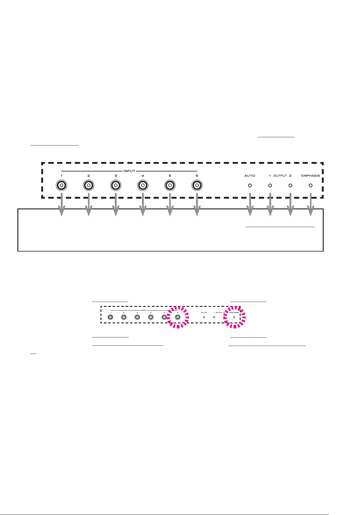
2. SERVICE MODE
Microprocessor (U12) version check
The firmware version is displayed on the front LED.
(Display time is only for 2 seconds.)
1. Connect the mains cord into the unit.
2. Press the POWER ON/STANDBY button for turn on the
unit.
3. Press the EMPHASIS and INPUT 1 buttons
simultaneously about 3 seconds.
4. LED light up in following order and version is displayed.
Lighting order : All LED light up → All LED turn off →
Version is displayed → Lighting of LED return to the
normal display (to quit Service Mode).
Microprocessor (U12) VERSION確認
FIRMWAREのバージョンはフロントパネルのLEDにて表示さ
れます。(表示は約
1. 本機に電源コードを接続します。
2. POWER ON/STANDBYボタンを押し、本機の電源をいれ
ます。
3. EMPHASISとINPUT 1 のボタンを同時に約3秒押しま
す。
4. LEDが下記の順序で点灯しバージョンを表示します。
点灯順序:全点灯 → 全消灯 → バージョン表示 → 通常表示
に戻ります。
2秒間のみです)
(SERVCICE モードは解除されます)
Version : [32] [16] [8] [4] [2] [1] [8] [4] [2] [1]
The number of decimal places
The firmware version is displayed in the lighting position
(Display time is only for 2 seconds) of LED.
Ex. :
Light up INPUT 6 [1] and EMPHASIS [1
Light up INPUT 6 [
Light up INPUT 6 [1] and EMPHASIS [
[2], Version: 1.3
1] and OUT PUT 2 [2], Version: 1.2
], Version: 1.1
1] / OUT PUT 2
小数点以下1桁の位
LED
表示例
が点灯した箇所(点灯は約2秒間)がバージョン表示で
す。
:
点灯INPUT 6 [1]と EMPHASIS [1]でVersion: 1.1
点灯INPUT 6 [1]と OUT PUT 2 [2]でVersion: 1.2
点灯INPUT 6 [1]とEMPHASIS [1] / OUT PUT 2 [2]で
Version: 1.3
3. UPDATE MICROPROCESSOR FIRMWARE
PROCEDURE
When microprocessor firmware of U12 (µ-PRO PWB) was
updated, update the firmware in the following procedure.
The updating of firmware takes about 5 seconds.
3. UPDATE MICROPROCESSOR FIRMWARE
PROCEDURE
U12 (µ-PRO PWB)マイコンのアップデートを行う際は、下記
の手順に従ってアップデートして下さい。
アップデートにかかる時間はおよそ
5秒です。
Necessary Equipment
• Windows PC (OS: Windows2000 or WindowsXP) with
Serial port.
• RS-232C Dsub-9 pin cable (female to female/straight
type).
• Update tool (Launch AND_PROGRAMMER.exe or
AND_Programmer_Setup.exe).
• Update data (ex.: vs3002_s_v1_20_0110.hex)
NOTE : AND_Programmer_Setup.exe is installer for Launch
AND_PROGRAMMER.exe.
The v1_20_0110 is version number. It will be
changed by version up.
Install Procedure
When the AND FIRMWARE UPGRADE PROGRAMMER
(Launch AND_PROGRAMMER.exe) is already installed,
please advance to the Update Procedure.
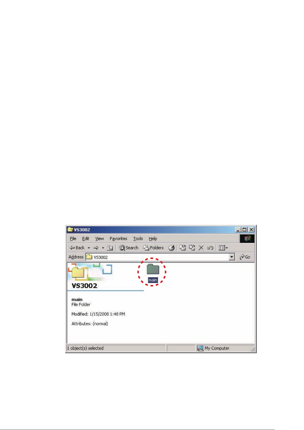
1. Put the "main" folder into anywhere on your PC's hard
disc.
2. Double click the "main" folder.
必要機器
• Windows PC (OS: Windows2000またはWindowsXP) で
Serialポートのあるもの
• RS-232Cストレートケーブル (9pinメス−9pinメス)
•
アップデート用書き込みソフトウェア (Launch AND_
PROGRAMMER.exe
exe)
•
アップデート用データ (ex.: vs3002_s_v1_20_0110.hex)
注意 : AND_Programmer_Setup.exeはLaunch AND_
PROGRAMMER.exe
ウェアです。
アップデート用データのファイル名にあるv1_20_0110は
バージョンを示します。これはバージョンアップにより
変更されます。
またはAND_Programmer_Setup.
をインストールするためのソフト
Install Procedure
既にAND FIRMWARE UPGRADE PROGRAMMER (Launch
AND_PROGRAMMER.exe)
は、
Update Procedureに進んでください。
1. "main"フォルダをPCの任意のフォルダにコピーします。
2. "main"フォルダをダブルクリックします。
がインストールされている場合
3
4
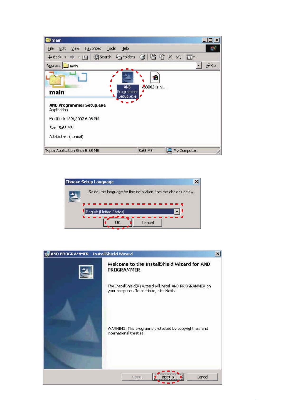
3. Double click the AND Programmer Setup.exe.
3. AND Programmer Setup.exeをダブルクリックします。
4. Choose the English (United States), and Click the OK.
5. Click the Next.
4. 言語をEnglish (United States)にし、OKをクリックしま
す。
5. Nextをクリックします。
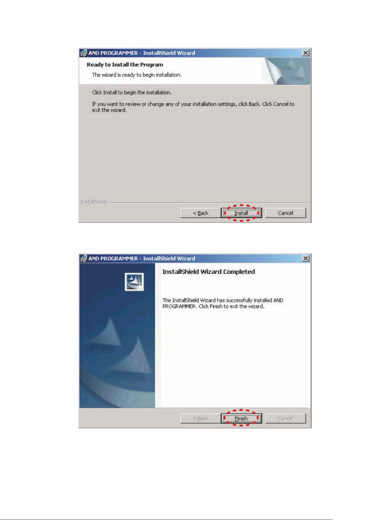
6. Click the Install.
6. Installをクリックします。
7. Click the Finish.
7. Finishをクリックします。
5
6
Update Procedure
1. Disconnect the mains cord from the unit.
2. Connect RS-232C on rear panel of the unit and the Serial
Port of Windows PC with RS-232C cable.
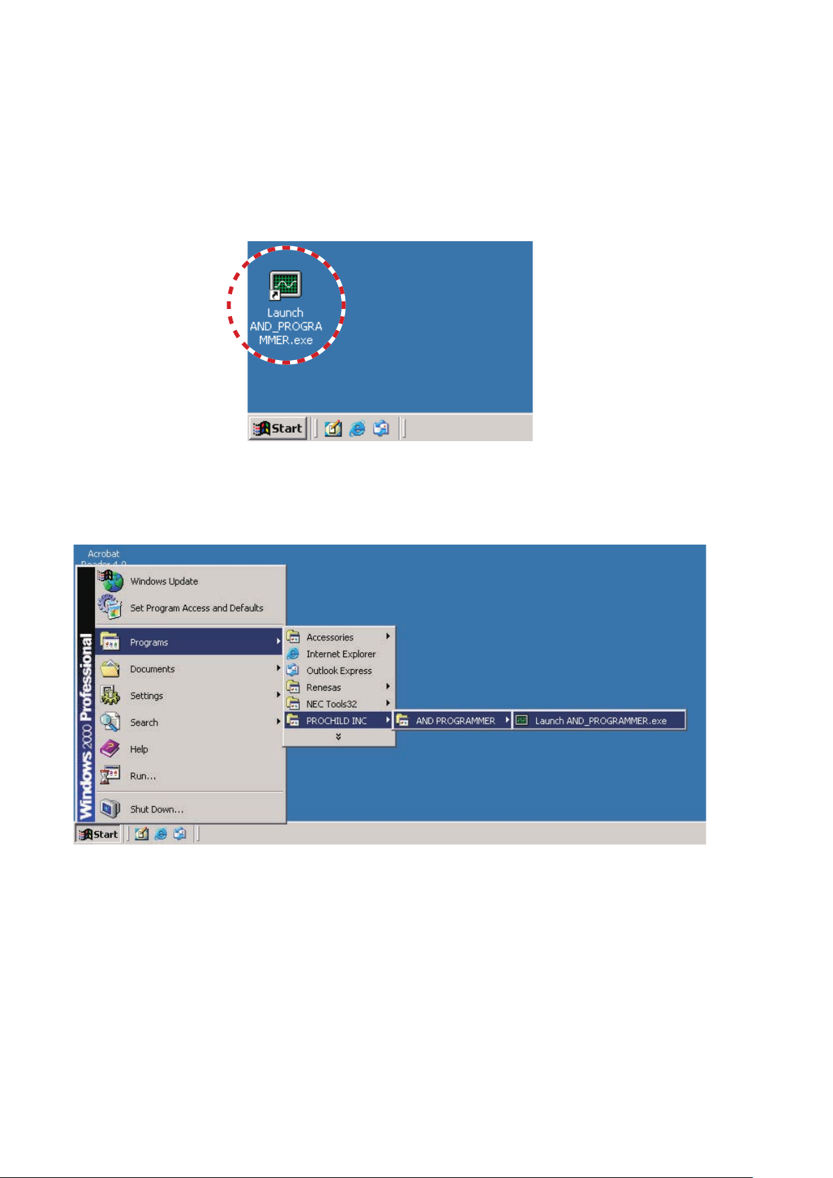
3. Launch the AND FIRMWARE UPGRADE
PROGRAMMER from two ways of following.
• Double click the Launch AND_PROGRAMMER.exe on
the desktop.
Update Procedure
1. 本機から電源ケーブルを外します。
2. 本機のリアパネルにあるRS-232C端子とPCのSerialポート
を
RS-232Cケーブルで接続します。
3. AND FIRMWARE UPGRADE PROGRAMMERを下記の
どちらかの方法で起動します。
• デスクトップにあるLaunch AND_PROGRAMMER.
exe
アイコンをダブルクリックします。
• Click the
PROGRAMMER and Launch AND_PROGRAMMER.
exe.
Start, Programs, PROCHILD INC, AND
• スタート、プログラム、PROCHILD INC,
AND PROGRAMMER, Launch AND_
PROGRAMMER.exe
をクリックします。
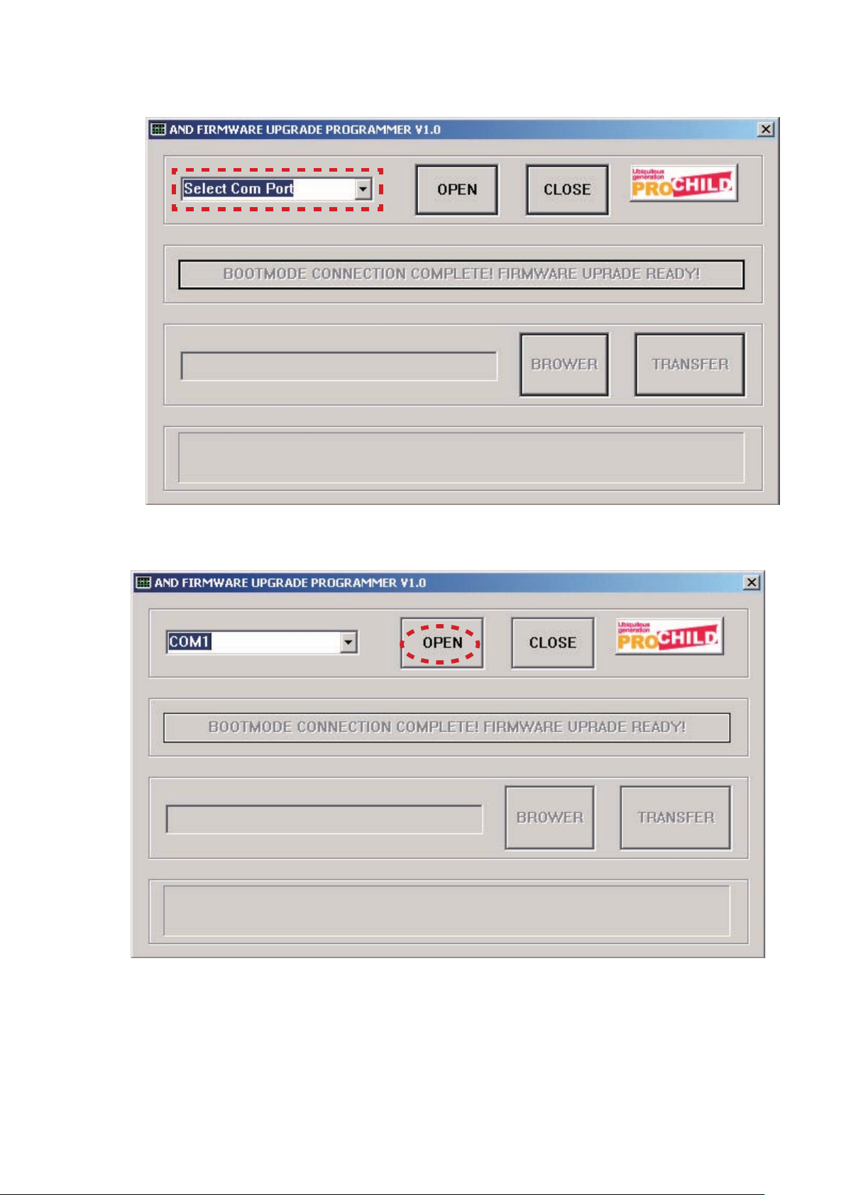
4. Choose the COM port number.
4. 使用するポート番号を選択します。
5. Click the OPEN.
5. OPENをクリックします。
6. Connect the mains cord into the unit.
NOTE : When the unit is into boot mode
not lights up.
, STANDBY LED is
6. 本機に電源ケーブルを接続します。
注意
: このとき本機はブートモードになり、STANDBY LEDは
点灯しません。
7
8
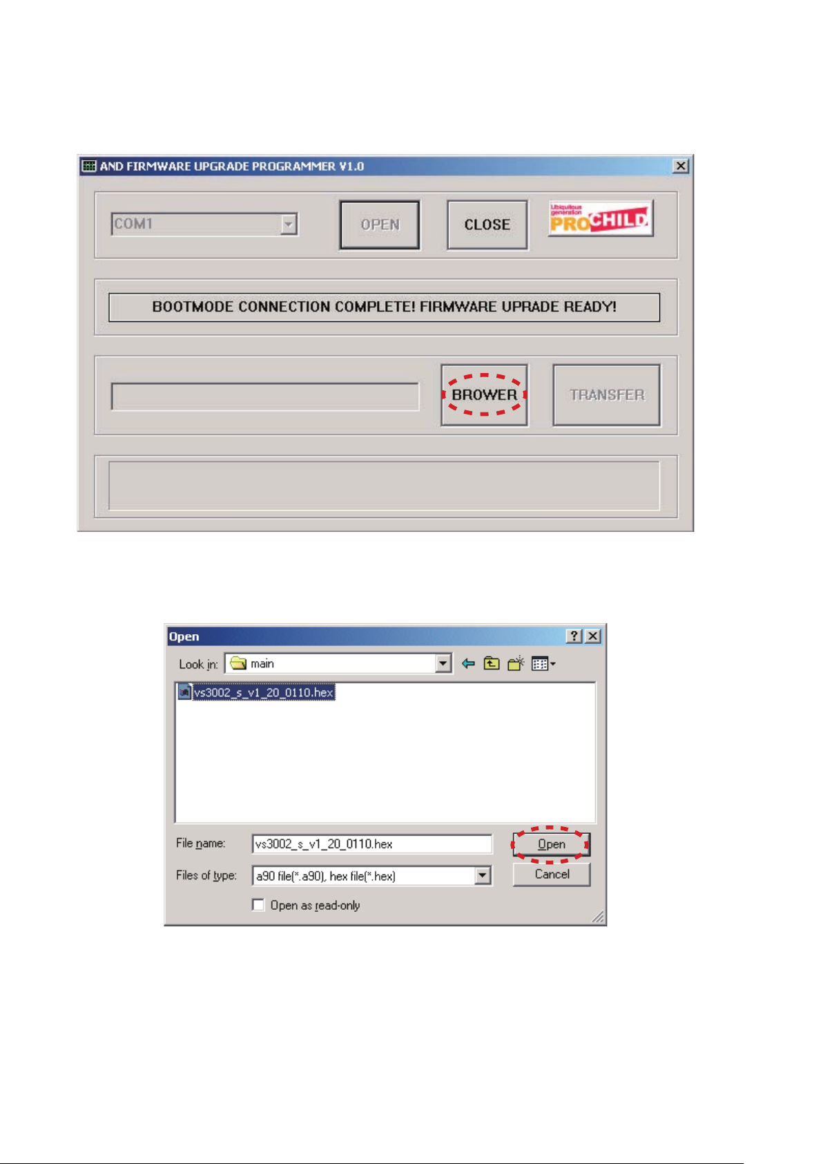
7. Check the massage "BOOTMODE CONNECTION
COMPLETE! FIRMWARE UPGRADE READY!" was
displayed. And click the BROWER.
7. "BOOTMODE CONNECTION COMPLETE! FIRMWARE
UPGRADE READY!"
が表示されたことを確認し、
BROWERをクリックします。
8. Choose the firmware (Ex.: vs3002_s_v1_20_011
And Click the Open.
0.hex).
8. アップデートするfirmware (例:vs3002_s_v1_20_0110.
hex)
を選択し、Openをクリックします。
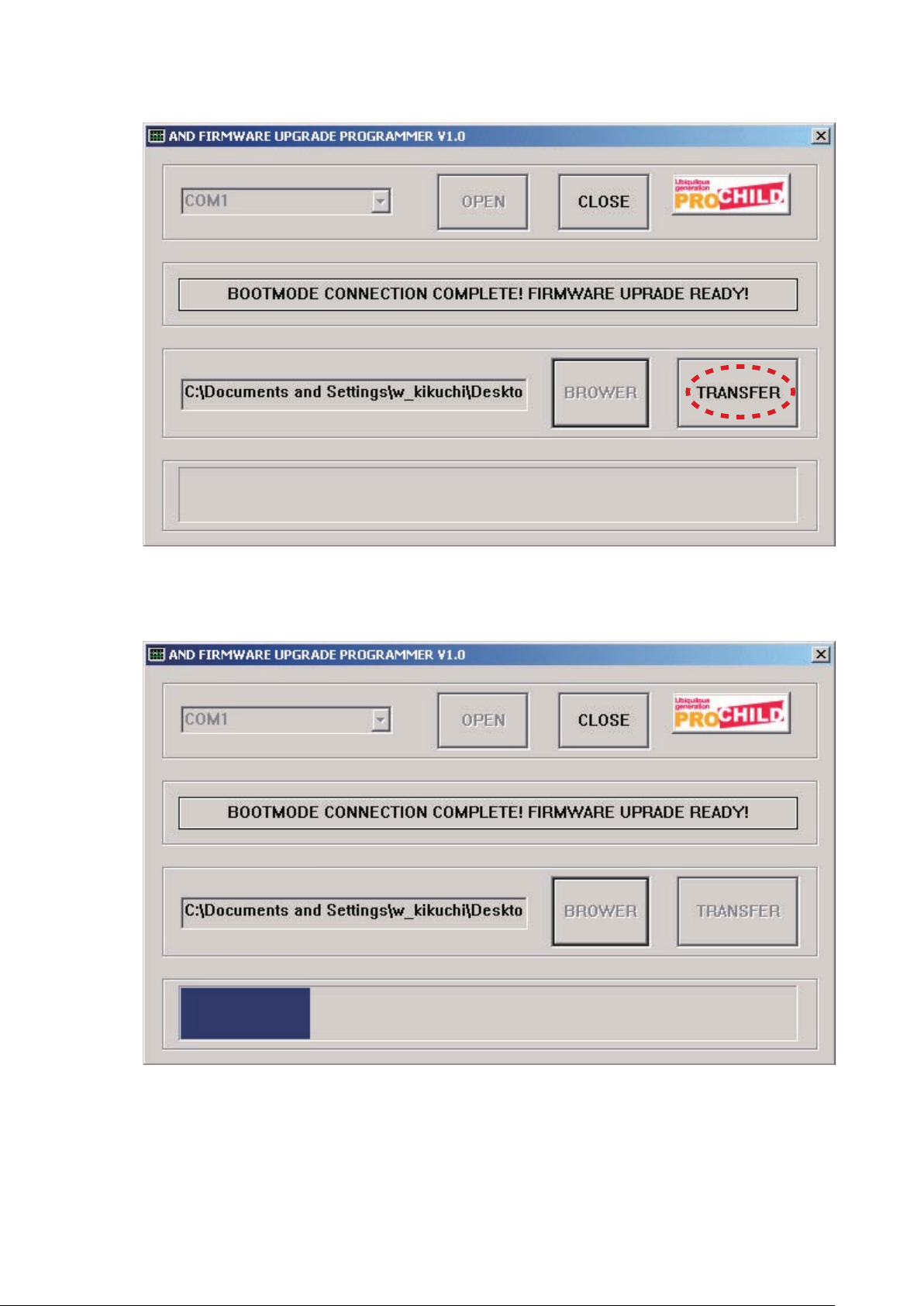
9. Click the TRANSFER.
9. TRANSFERをクリックします。
10. Firmware is written into the microprocessor.
The updating of firmware takes about 5 seconds.
10. Firmwareがマイコンに書き込まれます。
アップデートにかかる時間はおよそ5秒です。
9
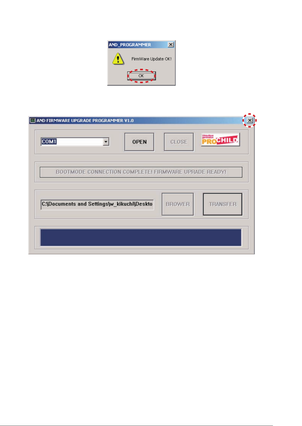
11. Click the OK.
11. OKをクリックします。
12. Click the X icon, and close the AND FIRMW
UPGRADE PROGRAMMER.
ARE
12. Xアイコンをクリックし、AND FIRMWARE UPGRADE
PROGRAMMER
を終了します。
13. Disconnect the mains cord and RS-232C cable from the
unit.
13. 電源コードとRS-232Cケーブルを本機から外します。
10
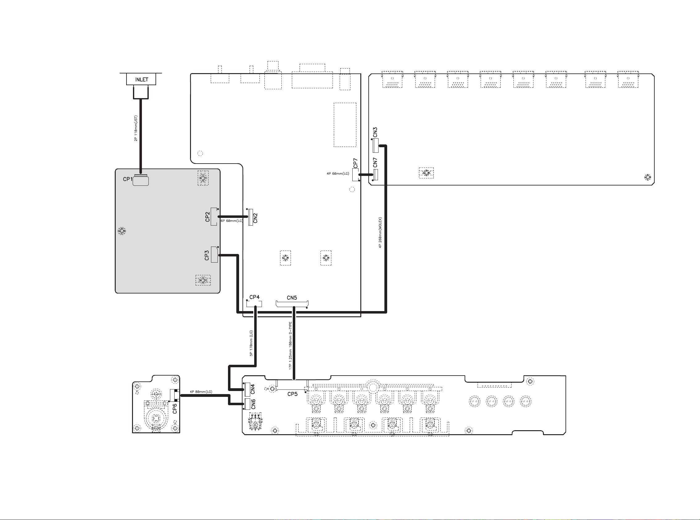
CN3
CN5CN4
CN6
CN1
CN7
CN2
FRONT PWB
µ-PRO PWB
HDMI PWB
STBY SW PWB
SMPS UNIT
(UNIT ASSY is replaced)
4. WIRING DIAGRAM
11 12
 Loading...