

Page 1

Service
VP-15S1/VP-15S1L
VP15S1 /F B/N1B/U1B
VP15S1L /N1B/U1B
Manual
DLP Projector
TABLE OF CONTENTS
SECTION PAG E
1. TECHNICAL SPECIFICATIONS.................................................................................................... 1
2. SERVICE TOOLS .......................................................................................................................... 1
3. ABOUT THE REPAIR METHOD ...................................................................................................2
4. DISASSEMBLE PROCEDURE .....................................................................................................3
5. COLOR WHEEL REPLACEMENT PROCEDURE / (Japan Ver.) .........................................9 / (11)
6. ADJUSTMENT PROCEDURE .................................................................................................... 13
7. TROUBLESHOOTING AND HINT / (Japan Ver.) ................................................................35/ (43)
8. WIRING DIAGRAM ..................................................................................................................... 63
9. BLOCK DIAGRAM ...................................................................................................................... 65
10. SCHEMATIC DIAGRAM .............................................................................................................. 67
11. PARTS LOCATION ...................................................................................................................... 91
12. MICROPROCESSOR AND IC DATA ........................................................................................... 99
13. EXPLODED VIEW AND PARTS LIST ....................................................................................... 107
14. ELECTRICAL PARTS LIST ....................................................................................................... 114
15. ABOUT REPLACE THE MICROPROCESSOR WITH A NEW ONE ......................................... 132
Please use this service manual with referring to the user guide ( D.F.U. ) without fail.
VP-15S1 / VP-15S1L
Part no. 90M29AV855010
First Issue 2007.08
MZ
Page 2

MARANTZ DESIGN AND SERVICE
Using superior design and selected high grade components,
Only original
MARANTZ
parts can insure that your
MARANTZ
MARANTZ
product will continue to perform to the specifi cations for which
company has created the ultimate in stereo sound.
it is famous.
Parts for your
MARANTZ
ORDERING PARTS :
equipment are generally available to our National Marantz Subsidiary or Agent.
Parts can be ordered either by mail or by Fax.. In both cases, the correct part number has to be specifi ed.
The following information must be supplied to eliminate delays in processing your order :
1. Complete address
2. Complete part numbers and quantities required
3. Description of parts
4. Model number for which part is required
5. Way of shipment
6. Signature : any order form or Fax. must be signed, otherwise such part order will be considered as null and void.
USA
MARANTZ AMERICA, INC
100 CORPORATE DRIVE
MAHWAH, NEW JERSEY 07430
USA
JAPAN
D&M Holdings Inc.
D&M BUILDING, 2-1 NISSHIN-CHO,
KAWASAKI-KU, KAWASAKI-SHI,
KANAGAWA, 210-8569 JAPAN
EUROPE / TRADING
MARANTZ EUROPE B.V.
P. O. BOX 8744, BUILDING SILVERPOINT
BEEMDSTRAAT 11, 5653 MA EINDHOVEN
THE NETHERLANDS
PHONE : +31 - 40 - 2507844
FAX : +31 - 40 - 2507860
CANADA
D&M CANADA INC.
5-505 APPLE CREEK BLVD.
MARKHAM, ONTARIO L3R 5B1
CANADA
KOREA
D&M SALES AND MARKETING KOREA LTD.
CHUNG JIN B/D., #1001,
53-5, WONHYORO 3 GA, YONGSAN-GU,
SEOUL, 140-719, KOREA
PHONE : +82 - 2 - 323 - 2155
FAX : +82 - 2 - 323 - 2154
CHINA
MARANTZ SHANGHAI TRADING LTD.
ROOM.506 SHANGHAI LIGHT INDUSTRY MANSION
1578 NANJING (WEST) ROAD SHANGHAI
CHINA
TEL : 021 - 6248 - 1064
FAX : 021 - 6248 - 3565
NOTE ON SAFETY :
Symbol Fire or electrical shock hazard. Only original parts should be used to replaced any part marked with symbol .
Any other component substitution (other than original type), may increase risk of fi re or electrical shock hazard.
安全上の注意:
がついている部品は、安全上重要な部品です。必ず指定されている部品番号のものを使用して下さい。
SHOCK, FIRE HAZARD SERVICE TEST :
CAUTION : After servicing this appliance and prior to returning to customer, measure the resistance between either primary AC
cord connector pins ( with unit NOT connected to AC mains and its Power switch ON ), and the face or Front Panel of product
and controls and chassis bottom.
Any resistance measurement less than 1 Megohms should cause unit to be repaired or corrected before AC power is applied,
and verifi ed before it is return to the user/customer.
Ref. UL Standard No. 60065.
In case of diffi culties, do not hesitate to contact the Technical
Department at above mentioned address.
070719MZ
Page 3
1. TECHNICAL SPECIFICATIONS
❖ Optical characteristics
Panel 0.95 inch 16:9
1920 x 1080 pixels
1080p DLP® chip
Lamp Super High Pressure 200W DC
Lens [VP-15S1] f: 30.7 to 44.5mm
[VP-15S1L] f: 44.5 to 66.75mm
Projection size 70 to 250 inches
❖ Input/Output
VIDEO IN RCA x 1
NTSC-3.58/PAL-4.43/SECAM
Composite video 1.0Vp-p/75 Ohm
S-VIDEO IN S-Connector x 1
NTSC-3.58/PAL-4.43/SECAM
S-Video
COMPONENT IN 3RCA x 2
Y, C
RGB/HD IN D-sub M 15 pin x 1
Analog RGB
HD:1080i/p, 720p, 480p
HDMI IN HDMI x 2
HDMI 1.3 compliant (single link only)
REMOTE CONTROLLER IN
Mini jack x 1
REMOTE CONTROLLER OUT
Mini jack x 1
AC IN 3 Prong Grounding Type
TRIG.1 OUT, TRIG.2 OUT
Mini Jack x 2
Output: DC12V or 0V, 100mA
RS232C RS232C receptacle plug x 1
B/PB
, CR/P
R
❖ General
Power requirement
[/F] AC 100V, 50/60 Hz
[/N] AC 230V, 50 Hz
[/U] AC 120V 60 Hz
Power consumption < 350 W
Standby consumption < 0.3 W (AC 100V, 120V)
< 0.5 W (AC 230V)
Chassis isolation Class-1
Safety UL60950-1
CSAC22.2 E60950
EN60950-1
J60950
EMC FCC Part-15 Class-B
EN55022 Class-B
Net weight 13 kg
Operating Temperature 5 to 35 °C
Operating humidity 30 to 85%
Storage Temperature – 20 to 60 °C
Storage humidity 30 to 85%
❖ Accessories
• Lens cap x 1
• Remote controller x 1
• Batteries x 2
• Mains code x 1
• User Guide
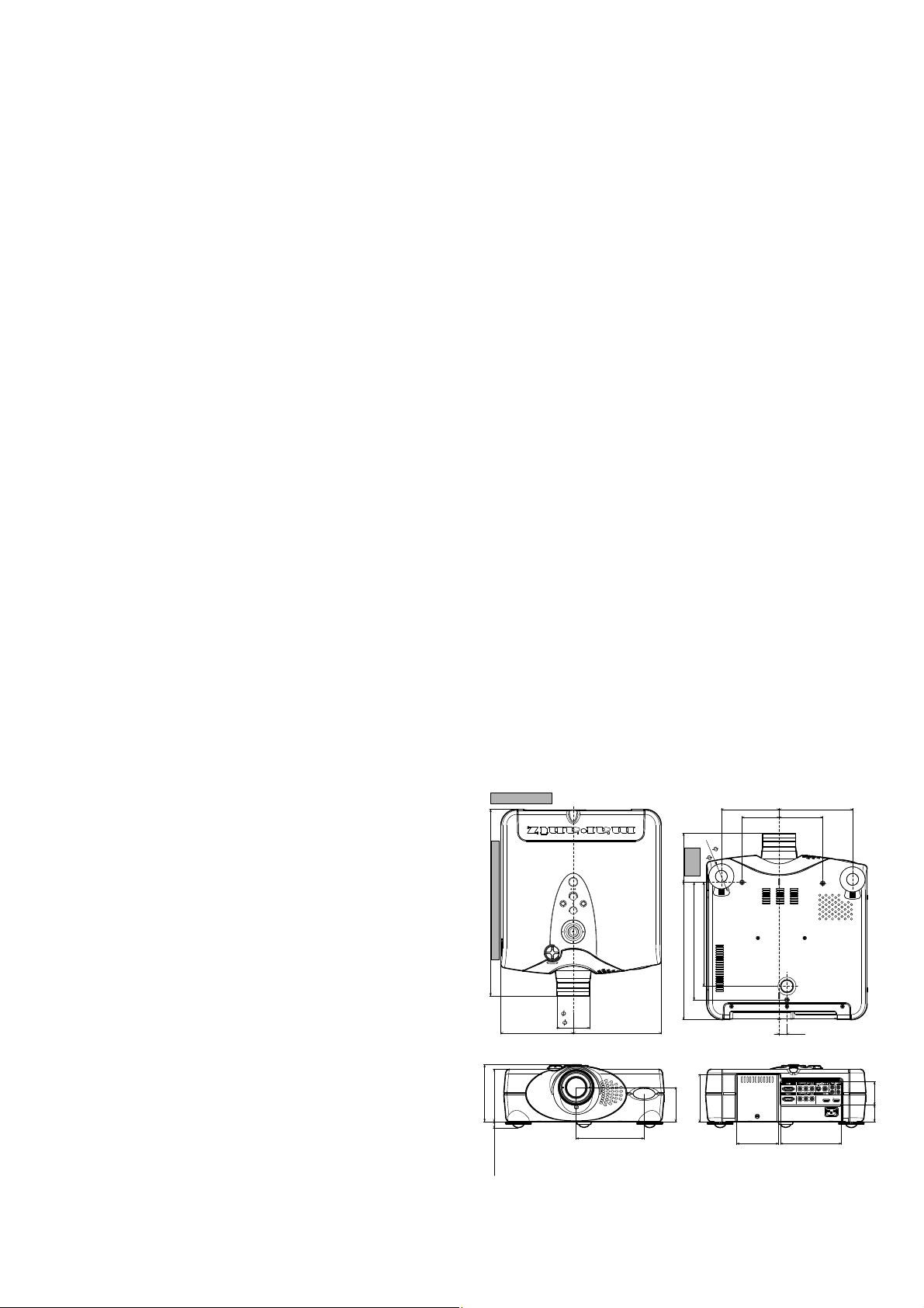
❖ Dimensions
[VP-15S1] 15 15/16(W) x 18 5/16(D) x 6 1/8(H) inch
404.5(W) x 489.5(D) x 158(H) mm
[VP-15S1L] 15 15/16(W) x 19 19/32(D) x 6 1/8(H) inch
404.5(W) x 497.5(D) x 158(H) mm
Top
VP-15S1L only
(142-143)
5 9/16 -55/8
Bottom
8/16
9/16
5
(141.0)
5 3/4
(145.75)
3 11/16
(93.5)
(64)
2
(185.25)
4 11/16
(110.0)
7 5/16
2. SERVICE TOOLS
• Windows PC.
• RS-232C cable straight type. (9 pin female - 9 pin female)
• Color temperature sensor ....................00MZK09AV0070
(Color Temperature Adj.)
18 1/4 -185/16 (488.5 - 489.5)
Front
5 5/8 (143.0)
5 3/16 (132.0)
9/16 - 2 7/16
(15.0 - 61.8)
1
19 9/16 - 19 19/32 (496.5 - 497.5)
7 3/16
(182.5)
3 1/4
( 82.6)
8 12/16
(222.0)
6 12/16 (171.0)
11 11/16 (296.5)
14 6/16 (346.5)
4 11/16 (119.0)
3-39/16 (76.0 - 91.0)
10 5/16 (262.0)
Rear
12/16
(19.75)
4 1/8 6 1/16
(105.0)
(153.5)
Unit : inch (mm)
2 5/16
1 10/16
(58.0)
(42.0)
Page 4

3. ABOUT THE REPAIR METHOD
基板及び光学エンジンのサービス部品供給について
修理方法
About service spare part supply of the PWB and OPTICAL ENGINE
When the PWB and the UNIT are repaired, confi rm contents of the following.
POS.NO DESCRIPTION How to repair
P101 FORMATTER PWB PWB ASSY is replaced
P201 FAN PWB Can be repaired on component level
P202 LEAF SWITCH PWB Can be repaired on component level
P301 DMD PWB Repair isn’t allowed : UN04 is replaced (DMD PWB and OPTICAL
ENGINE:UN04 are harmonized)
P501 IO PWB Can be repaired on component level
P601 HDMI PWB PWB ASSY is replaced
P701* / P801 SSB1 PWB / SSB2 PWB PWB ASSY is replaced (Replace P701and P801 in pairs)
P801 can be repaired on component level
PK00* P701* / P801 PWB ASSY KIT PWB ASSY is replaced (Replace P701and P801 in pairs)
P901 IR-F PWB Can be repaired on component level
P902 IR-R PWB Can be repaired on component level
P903 KEY PWB Can be repaired on component level
P904 INLET PWB Can be repaired on component level
UN01 LAMP POWER SUPPLY PWB PWB ASSY is replaced
UN02 POWER SUPPLY PWB ASSY is replaced
LU-12VPS3 (UN03) LAMP UNIT LAMP UNIT(LU-12VPS3) is replaced
UN04* UNIT KIT OPTICAL ENGINE UNIT KIT is replaced
(DMD PWB:P301 and OPTICAL ENGINE are harmonized)
* : When P701, PK00 or UN04 are replaced, 13-page adjustment is required.
基板及び光学エンジンのサービス部品供給について
のサービス部品の供給内容を「単品部品で修理」、「完成品で交換」、「修理不可」に区別し下記に記載します。
本体
POS.NO DESCRIPTION
P101 FORMATTER PWB
P201 FAN PWB
P202 LEAF SWITCH PWB
P301 DMD PWB
P501 IO PWB
P601 HDMI PWB
P701* / P801 SSB1 PWB / SSB2 PWB
PK00* P701* / P801 PWB ASSY KIT PWB
P901 IR-F PWB
P902 IR-R PWB
P903 KEY PWB
P904 INLET PWB
UN01 LAMP POWER SUPPLY PWB
UN02 POWER SUPPLY
LU-12VPS3 (UN03) LAMP UNIT LAMP UNIT(LU-12VPS3)
UN04* UNIT KIT OPTICAL ENGINE
: P701, PK00
*
または
UN
From J310(P701)
LENS SHIFT SW
を交換したときは、13頁の調整が必要です。
04
修理方法
PWB
完成品で交換
単品部品で修理できます(
単品部品で修理できます(
修理を許可しません(
単品部品で修理できます(
PWB
完成品で交換
PWB
完成品で交換(
P801
は単品部品での修理も可能です。
完成品で交換。(
単品部品で修理できます(PWB 完成品の供給はありません)
単品部品で修理できます(PWB 完成品の供給はありません)
単品部品で修理できます(PWB 完成品の供給はありません)
単品部品で修理できます(
PWB
完成品で交換
PWB
完成品で交換
修理を許可しません
PWB
完成品の供給はありません)
PWB
完成品の供給はありません)
OPTICAL ENGINE:UN04
PWB
完成品の供給はありません)
P701とP801
P
701
PWB
で交換
(UNIT KIT
のペアで交換)
と
のペア)
P
801
完成品の供給はありません)
UN03(LAMP)
で交換、含む
P301
DMD PWB
と一体です)
のみの交換も可能
DMD PWB)
From J205(P201)
LENS IRIS
From J211(P201)
ILLUMINATION IRIS
UN04 UNIT KIT
OPTICAL ENGINE
2
035G
Color wheel
From J224(P201)
CW SENSOR
From J221(P201)
CW DRIVE
Page 5

4. DISASSEMBLE PROCEDURE
フォーカスレンズ及びズームリングの取り外し
フロントカバーの取り外し
リアパネルの取り外し
注)
注)
1. Disassemble of the lens ring.
1) Turn the ring (170B) counter clockwise and remove the ring.
2) Remove 3 screws (167B) and remove the focus ring (165B).
3) Remove 3 screws (162B) and remove the zoom ring (160B).
Fig.1
フォーカスレンズ及びズームリングの取り外し
1.
1
)リング
2
)ネジ
3
)ネジ
2. Disassemble of the front cover.
1) Remove the cap (154B) with a minus driver, as shown in a
2) Remove 2 screws (152B) and 1 screw (153B) from the front
3) The front cover is locked by 4 hooks (A to D). The part of
Fig.2
フロントカバーの取り外し
2.
1
)キヤップ
2
)ネジ
3
)フロントカバーにはフックA~Dが有ります。フロントカバ
(170B)
を矢印方向に回し取り外します。
(167B) 3
本を外しフォーカスリング
(165B)
を取り外しま
す。
(162B) 3
本を外しズームリング
(160B)
を取り外します。
fi gure.
cover.
the C, D are strongly pulled to the direction shown and
remove it.
(154B)
を図の様にドライバーで取り外します。
(152B) 2本, (153B) 1
本を外しフロントカバーを取り外
します。
ーを両手でフック
C, D
部に指を掛け手前に強く引き矢印方向
に取り出します。
FRONT COVER
150B
C
152B
154B
170B
A
167B
160B
162B
165B
167B
A
B
162B
162B
Fig.1
Caution
Never touch these screws.
注) このネジに触れてはいけません。
B
D
153B
Fig.2
A
B
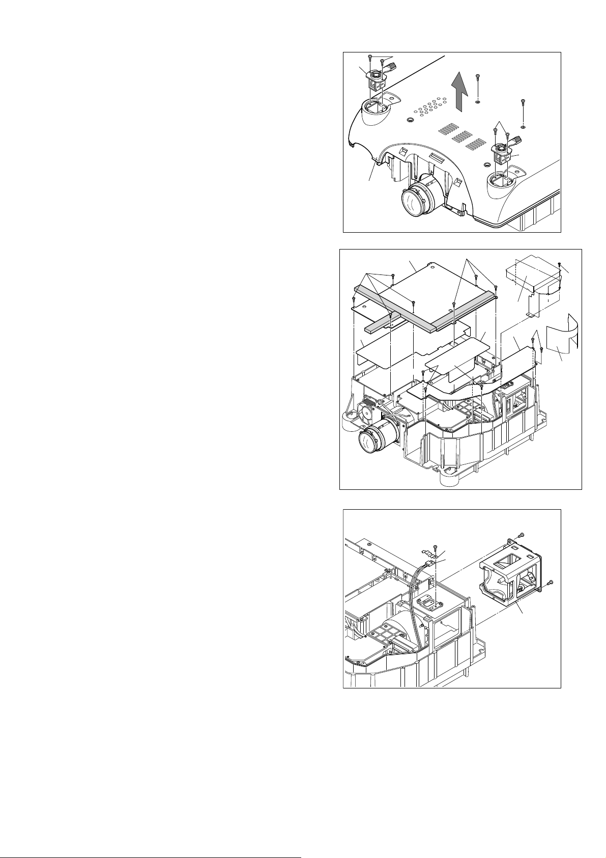
3. Disassemble of the rear panel.
1) Remove 3 screws (120B) from the rear panel.
2) Disconnect the connector (J331) from the IR-R PWB (P902).
Cautions in disassembling
When removing the rear panel, take care not to damage the
cable for the IR sensor and lights.
Since the IR window (110B) fends to get damaged, the IR
window should not put the IR window downward.
Fig.3
リアパネルの取り外し
3.
1
2
(120B) 3
)ネジ
本を外します。
)両手でリアパネルの下側に指を掛け手前に回転する様に少し引
き出します。
3)IR-R
基板
(P902)
に接続されているコネクター
(J331)
を取り外
します。
4
)リアパネルを矢印方向に取り出します。
注)IRセンサーのリード線が接続されているのでリアパネルは少
しだけ引き出しコネクターを取り外します。
IR
ウィンドウ
(110B)
がキズ付きやすいので、
IR
ウィンドウ
を下向きに置かないで下さい。
3
120B
Fig.3
J331
P902
120B
110B
REAR PANEL
100B
120B
Page 6

4. Disassemble of the top case.
トップケースの取り外し
ボトムケースの取り外し
1) Remove 4 screws (200B), 3 screws (045B) and the screw
(202B) from the top and bottom case.
2) Disconnect the 2 connectors (J334 and J329) from the top
case.
3) Remove the top case (001B) vertically.
Cautions in disassembling
When removing the top case, take care not to damage the
cable for the IR sensor, inside of set the product and key
control.
Fig.4
トップケースの取り外し
4.
1
2
3
(200B) 4本, (045B) 3本, (202B) 1
)ネジ
)コネクター
(J329, J334) 2
個所を取り外します。
)トップケースを矢印方向に取り外します。
本を外します。
注)IRセンサー及び本体内部とトップケース基板にリード線が接
続されているのでトップケースを少し持ち上げてコネクター
を取り外します。
200B
202B
200B
TOP CASE
001B
IR SENSOR
J334
J329
Fig.4
045B
045B
045B
200B
200B
5. Disassemble of the bottom case.
1) Remove 2 E-rings (040C) and 2 washers (041C).
2) The set is turned over, then turn the lever(arrow A) and
remove the leg (arrow B) vertically.
Cautions
When turning the set over, take care not to damage the
lens shift shaft.
Fig.5-1
ボトムケースの取り外し
5.
1)E
2
)本体を裏返してレバーを矢印Aの方向に回し,脚を矢印
リング
(040C) 2
個、ワッシャ
(041C) 2
個を取り外します。
B
の方向へ引き抜いて下さい。
注)レンズシフトシャフトが本体より出張っています。本体を
反転する時はレンズシフトシャフトが直接テーブル等に当
たらないように置いて下さい。
3) Remove 4 screws. (321G)
Fig.5-2
3
)ネジ
(321G) 4
本を取り外します。
LENS SHIFT SHAFT
040C
041C
LEG
B
A
LEVER
Fig.5-1
321G
321G
321G
321G
Fig.5-2
4
Page 7
4) Remove 2 screws. (059B)
温度センサー及びランプブラケットの取り外し
トップケース側基板シールド及びダクトシールドの取り外し
5) Remove the adjusters (001C) and 4 screws. (045C)
6) Remove the bottom case (050B) vertically.
Fig.5-3
4
5
6
(059B) 2
)ネジ
(045C) 4
)ネジ
)ボトムケース
本を外します。
本を外しアジャスタ
(050B)
を矢印方向に引き上げて取り外します。
(001C)
を取り外します。
6. Disassemble of the PWB shield and the duct shield.
(Top case side).
1) Remove 7 screws (217G), 3 screws (202G) and remove the
PWB shield (215G), color wheel cover (191G).
2) Remove 3 insulators (338G, 340G and 486G).
3) Remove 6 screws (202G) and remove the duct shield
(200G).
Fig.6
トップケース側基板シールド及びダクトシールドの取り外し
6.
1
2
3
(217G) 7
)ネジ
本とネジ
とカラーホイールカバー
)インシュレータ
(202G) 6
)ネ ジ
(338G), (340G)と(486G)
本を外しダクトシールド
(202G) 3
(191G)
本を外し基板シールド
を取り外します。
を取り外します。
(200G)
を取り外します。
(215G)
001C
340G
050B
217G
045C
215G
202G
Fig.5-3
202G
217G
059B
338G
045C
191G
200G
059B
001C
202G
202G
486G
7. Disassemble of the thermal sensor and lamp bracket.
1) Remove the screw. (308G)
2) Remove the clamp (306G) and remove thermal sensor
(TH02).
3) Remove the 2 screws (180G) and remove lamp bracket
(160G)
Fig.7
温度センサー及びランプブラケットの取り外し
7.
1
2
3
(308G) 1
)ネジ
)クランパー
(180G) 2
)ネジ
本を外します。
(306G)
を取り外し温度センサーを取り外します。
本を外しランプブラケットを引き出します。
Fig.6
308G
Fig.7
306G
SENSOR
TH02
180G
BRACKET LAMP
160G
180G
5
Page 8

g
8. Disassemble of the OPTICAL ENGINE unit.
光学エンジンユニットの取り外し
電源ユニット及び
ユニットの取り外し
1) To remove a OPTICAL ENGINE unit (UN04), a procedure
(Fig.10 - Fig.13) is required. Because the screw (157G) is
hidden by the duct of the fan for lamp cooling (M703).
2) Disconnect 4 connectors from (J205, J211, J221, J224) on
P201. (See fi g. 11)
3) Remove the 6 screws (155G) and 2 screws (157G), after
the process 1).
4) Remove the 2 screws (153G) for the lamp connector, and
remove the lens base (UN04) and the lamp case (150G)
vertically.
Cautions
When removing the lens base, please be sure to lift the lens
base main part.
Do NOT touch the lens part.
Fig.8
光学エンジンユニットの取り外し
8.
1
)光学エンジンユニット
(UN04)
を取り外すには、図10~図
13
の手順を参照して下さい。
注)ランプ冷却用ファン
1
本が有りますので取り外します。
2
)
P201
のコネクター
ます。(図11参照
3)図10
4
)ランプコネクター取り付けネジ
~図13の分解を全て修了後にネジ
(157G) 2
ス
本を取り外します。
(UN04)
とランプケース
(M703)
(J205, J211, J221, J224) 4
)
のダクト部の下にもネジ
(155G) 6
(153G) 2
(150G)
本を外しレンズベー
を取り外します。
(157G)
個所を取り外し
本及びネジ
注)レンズベースを取り外す時はレンズ部分には触れずに必ずレ
ンズベース本体を持って取り外して下さい。
LENS BASE
J021
UN04
155G
Fi
LAMP CASE
150G
157G
.8
153G
157G
155G
9. Disassemble of the POWER SUPPLY UNIT and the
BALLAST UNIT.
1) Remove 6 screws (022G).
2) Disconnect 7 connectors (CN1, CN2, A:CN3-CN7) and
remove the POWER SUPPLY UNIT (UN02).
3) Remove 4 screws (207G) and remove the BALLAST UNIT
(UN01).
Cautions
· When removing the POWER SUPPLY UNIT (UN02),
remove 3 PWBs and loose the cables that is fi xing the
cables in opposite side main chassis. (See fi g. 12)
Because cables of POWER SUPPLY UNIT (UN02) is fi xed
on opposite side main chassis under the 3 PWBs.
· When removing the BALLAST UNIT (UN01), remove the
lens base before. (See fi g. 8) The lamp connector was fi xed
between the main chassis and the lens base.
Fig.9
電源ユニット及び
9.
注)電源ユニット
BALLAST
(UN02)
ユニットの取り外し
を取り外すには、ボトム側に電源ユニッ
トのリード線が固定されている為、ネジを外してもユニットは
取り出せません。ボトム側の基板3枚を取り出し(図12参照
リード線をゆるめて外します。
1
2
(022G) 6
)ネジ
)コネクター
本を外します。
(CN1, CN2, A:CN3~CN7) 7
個を取り外し電源ユ
ニットを取り外します。
POWER SUPPLY UNIT(UN02)
022G
)
022G
CN1
C
207G
207G
BALLAST UNIT(UN01)
LAMP CONNETOR
D
CN2
A
B
Fig.9
6
Page 9
ボトム側基板シールドの取り外し
基板
及び
基板
の取り
外し
3
注)
)ネジ
BALLAST
(207G) 4
本を外し
BALLAST
ユニットを取り外します。
ユニットを取り外すには、ランプコネクターがレン
ズベースの下側に有りますのでレンズベースを取り外して下
さい。( 図8参照
)
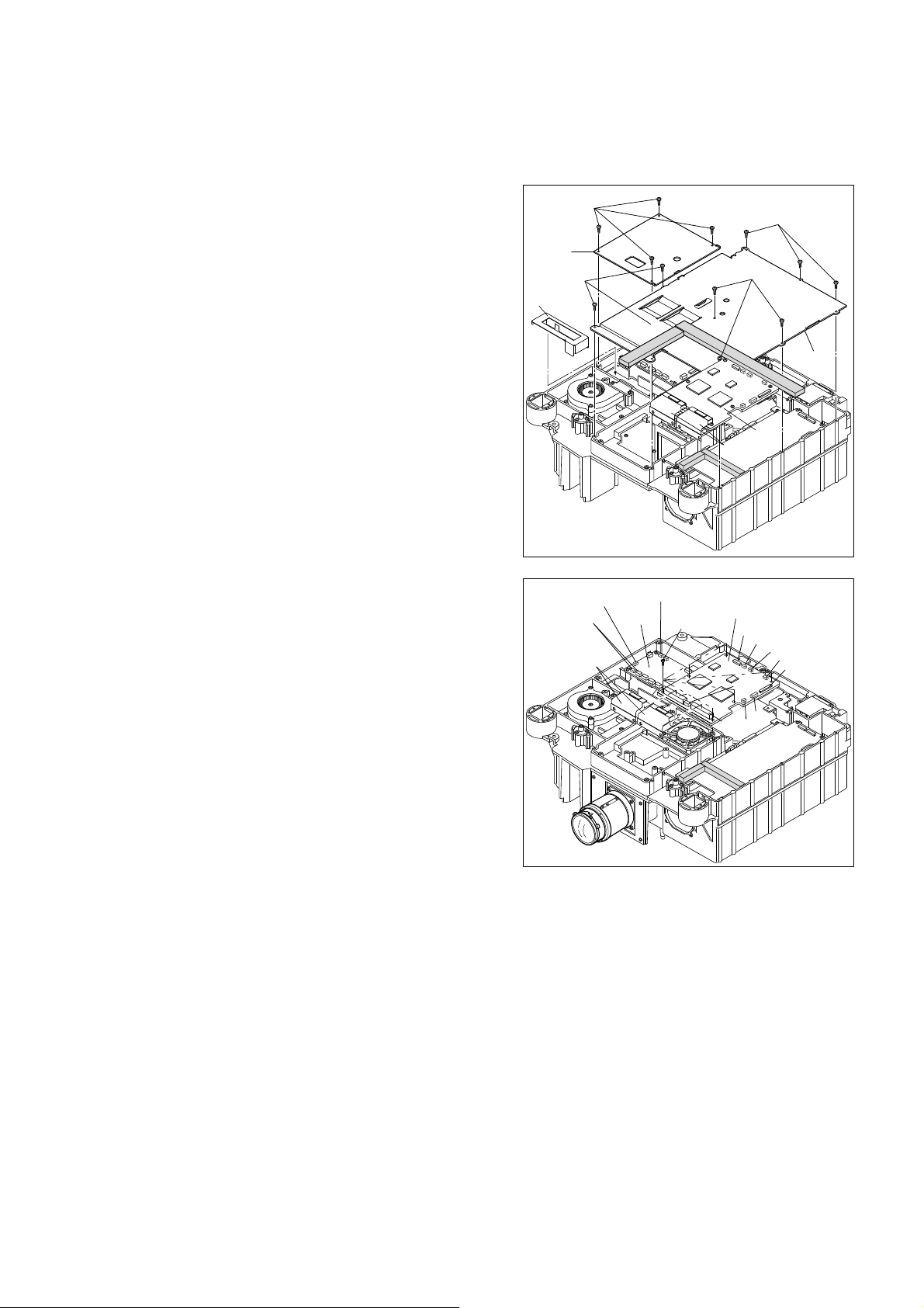
10. Disassemble of the shield for PWB of bottom side.
1) Remove 4 screws (311G) and remove the shield (310G) for
PWB.
2) Remove 9 screws (302G) and the shield (300G) for PWB.
3) Remove the cover (484G).
Fig.10
ボトム側基板シールドの取り外し
10.
1
2
3
)ネジ
)ネジ
)カバー
(311G) 4
(302G) 9
(484G)
本を外し基板シールド
本を外し基板シールド
を取り外します。
(310G)
を取り外します。
(300G)
を取り外します。
11. Disassemble of the FORMATTER PWB and the EXTEND
PWB.
1) Remove 4 screws (135G).
2) Disconnect 8 connectors (J001, J004, J005, J007 - J009,
J011 and J012).
3) FORMATTER PWB (P101) is connected with EXTEND
PWB (P400) by the connector (J002, J003). Pll out the
connector.
4). Remove the EXTEND PWB (P400) from PWB support
(132G).
Fig.11
11. FORMATTER
外し
1
2
3
(135G) 4
)ネジ
)コネクター
8
個所を取り外します。
)基板
(
J001, J004, J005, J007 - J009, J011and J012
(P101)
は基板
れています、基板
(
P101
)
及び
基板
本を取り外します。
(P400)
とコネクター
(P400)
を上側に持ち上げて基板
EXTEND
(
基板
P400
(
J002, J003
)
)
接続さ
(P101)
の取り
)
を
取り外します。
4
)
PWB
サポート
(132G)
から基板
(P400)
を取り外します。
310G
302G
484G
J224, J221
EXTEND PWB
311G
J211
P400 x 2
FAN PWB
P201
Fig.10
J205
135G
J003
Fig.11
302G
302G
P101
P400 x 2
FORMATER PWB
P101
J005
J008
J011
J004
J007
J009
J002
J012
J001
300G
7
Page 10

12. Disassemble of the SSB2 PWB, the SSB1 PWB and the
SSB2 基板
(P801)
及び SSB1 基板
(P701),
HDMI 基板
(P601)
の取り外し
基板取り付けブラケット及びランプ冷却ファンブロックの取り
外し
HDMI PWB.
1) Remove 3 screws (247G) and the screw (250G).
2) Disconnect 3 connectors (A : J501, J502 and J503) and the
FPC(J505).
Caution
When remove FPC (J505, JF02), a stopper is moved as
shown fi gure, and pull out FPC.
3) Remove the SSB2 PWB (P801) vertically.
4) Remove the 6 screws (250G).
5) Disconnect the 10 connectors. (B-G : J310, J301, J302,
J305, J702, J303, J311, J314, J304, J309)
6) Remove the SSB1 PWB (P701) vertically.
7) Remove 4 screws (237G) and 2 screws (241G), then remove
the HDMI PWB (P601).
Caution
When removing P601, Don’t strike against the chassis.
There is fear of part destruction.
Fig.12
12.
SSB2 基板
の取り外し
1
)ネジ
2)A部
(P801)
及び SSB1 基板
(247G) 3
本とネジ
コネクター 3個所
(250G) 1
(J501, J502, J503)とFPC(J505)1
(P701),
HDMI 基板
本を取り外します。
(P601)
個所
を取り外します。
注)コネクタ (
図のように動かしてから
3
)基板
側に持ち上げて基板
4
)ネジ
5)B~G部
J303, J311, J314, J304, J309)
6
)基板
7
)ネジ
J505, JF02)のFPC
FPC
を抜きます。
(P801)
(250G)6
コネクター
(P701)
は基板
(P801)
本を外します。
10
とコネクター接続されています、上
を取り外します。
(J310, J301, J302, J305, J702,
個所
を取り外します。
(P701)
は上側に持ち上げて取り外します。
(237G) 4
本とネジ
(241G) 2
取り外しは、ストッパー部を
本を外し、基板
(P601)
を取
り外します。
注)基板
(P601)
を取り外すさい、シャーシにぶっつけないよう注
意します。部品を破壊する恐れがあります。
250G
044Gx2
042G
247G
SSB2 PWB
B
250G
P601
HDMI PWB
Fig.12
P801
C
236Gx4
250G
D
E
250G
A
237Gx4
235G
x2
A
A
247G
F
G
M703
046Gx3
250G
P701
SSB1 PWB
241Gx2
239G
Stopper
13. Disassemble of the bracket and the fan Block for lamp
cooling.
1) Remove 2 screws (232G) and remove the bracket (230G).
2) Remove 3 screws (048G) and the fan Block for lamp cooling
(M703, M705).
Fig.13
基板取り付けブラケット及びランプ冷却ファンブロックの取り
13.
外し
1
2
)ネジ
)ネジ
M705)
(232G) 2
(048G) 3
本を外しブラケット
本を外しランプ冷却ファンブロック
を取り外します。
(230G)
を取り外します。
(M703,
8
FAN PWB
P201
038G
034G
030G
036G
048G
Fig.13
048G
040Gx2
M705
048G
232G
032G
x2
A
230G
A
Page 11

5. COLOR WHEEL REPLACEMENT PROCEDURE
1. Remove the 4 screws shown in the picture below and
remove the top cover of the optical engine.
Remove screw
Top cover
2. Remove the 2 screws shown in the picture below and
remove the bottom cover of the optical engine.
Bottom cover
4. Remove the screws at the front and back sides of the
color wheel and remove the color wheel cover.
Remove screw
3. Remove the condenser lens part.
Remove screw
Remove screws
Condenser
Remove color wheel cover
9
Page 12

5. Remove the 3 hex-screws then remove the color wheel.
Remove hex-screws
(Caution)
The rubber dumper are glued to the color wheel, Be
careful and remove.
The color wheel of VP-15S1 is not the same as VP-11S1,
VP12S1 to VP12S4 and VP13S1.
Be careful when exchange the color wheel.
Please check the part number under Rubber dumper.
Rubber dumper
(Caution)
Rubber dumper is in between the color wheel and the
optical engine, so it can be hard to remove the color
wheel. If it is diffi cult to remove the rubber dumper and the
color wheel, use a minus screw driver to remove those.
Be careful not to make a scratch on the color wheel fi lter.
6. Before assembling the color wheel, remove the rubber
dumpers form the optical engine then put them on to the
color wheel as shown in the picture below.
VP15S1 Color wheel model no.: 102299690
7. Adopt the color wheel to the optical engine and put on
the color wheel cover.
(Caution)
Do not push the motor part hard when putting on the
color wheel. It may break the motor. (Rotating noise may
become bigger)
8. Adjust the color wheel by following the Color Wheel
Adjustment Procedure.
Rubber dumper 1
Rubber dumper 2
10
Page 13

カラーホイール交換手順
5. COLOR WHEEL REPLACEMENT PROCEDURE
カラーホイール交換手順
1
. 下図の 4 箇所のネジを外し、光学エンジンの表側カバーを
外す。
表側カバー
2. 下図の 2 ヶ所のネジを外し、光学エンジンの裏側カバーを
外す。
4. カラーホイール前後のネジを外し、カラーホイールカバ
ーを外す。
ネジ
3. コンデンサレンズ部を外す。
ネジ
ネジ
コンデンサレンズ部
カラーホイールカバー
11
Page 14

. 3 ヶ所の六角ネジを外し、カラーホイールを外す。
5
ネジ
(注意)
振動防止ゴム
外し時注意してください。
VP-15S1 に使用しているカラーホイールは VP-11S1,
VP-12S1 〜 VP12-S4
間違いのないよう交換時注意してください。
振動防止ゴムの下の型番号を確認してください。
1、2 は、同じものを再び使用します。取り
, VP13S1 と共通ではありません。
振動防止ゴム
(注意)
カラーホイールと光学エンジンの間に振動防止ゴムが挟ま
っている為、外しにくい時があります。もし外れない時は、
カラーホイールのフィルターが傷つかないように、マイナ
スドライバー等でゴムとカラーホイールを外して下さい。
6. カラーホイールを取り付ける前に、振動防止ゴムを光学エ
ンジンから取り外し、下図のようにカラーホイールに取り
付けて下さい。
7.
(注意)
取り付ける時に、モーター部を強く押して取り付けないよ
モーターが破損する恐れがあります。(回転音が大きくな
VP-15S1 カラーホイール型番:102299690
カラーホイールを光学エンジンに取り付け、カラーホイー
ルカバーを取り付ける。
うにして下さい。
る原因となります。)
8. カラーホイールの調整方法に従い、再調整を行って下さい。
振動防止ゴム
振動防止ゴム 2
1
12
Page 15

6. ADJUSTMENT PROCEDURE
各調整が必要な場合
[A]
カラーホイールの調整手順
準備するもの
接続
プログラムの起動と設定
Cases Adjustment is needed
P701 PWB Board PK00 SSB PWB Kit 035G Color wheel UN04 Optical Engine
Color Wheel Adjustment
カラーホ イール調 整
Color Temperature Adjustment
色温度補正
Serial Number Inastall
シリアルナンバー書込み
Comfi rm of Software Version
ソフトウェアーヴァージョンの確認
AD9888 adjustment
ADC 調整
○○○ ○
○○○ ○
○○
○○
△
△: If the black image from the component or the RGB terminal is visible of some color, then please adjust.
△: コンポーネントもしくは RGB 端子からの黒画面で何らかの色が見える場合、調整を行ってください。
[A] Color Wheel Adjustment Procedure
1. Necessary Equipments
A service remote controller that can output the RC5
code "16 63 63". (The unit can adjust without a service
remote controller)
2. Connections
Confi rm that power cord is not connected to the UNIT.
3. Adjustment
1) Pressing the 3 buttons LEFT, ENTER, INPUT on the
unit within 10 seconds after turning on power or RC5
code "16 63 63" is sent using service remote, and turn
into the service mode.
2) With the direction buttons, up, down, left and right, select
"Optics Check" under "Optics Check".
各調整が必要な場合
Replaced item 交換したアイテム
[A]
カラーホイールの調整手順
1.
準備するもの
RC5 コード "16 63 63" が出せるサービスリモコン
( サービスリモコンを使用せず、本体のみで調整できます )
2.
接続
本体に電源ケーブルが接続されていないことを確認します。
3.
プログラムの起動と設定
1) 電源投入後 10 秒以内に本体の LEFT、ENTER、INPUT
の 3 つのボタンを同時に押してサービスモードに入ります。
または、サービスリモコンを使い
を送りサービスモードに入ります。
2) 上下左右の矢印ボタンを使い、"Optics Check" の "Optics
Check" を選択します。
RC5 コード "16 63 63"
3) Press the THROUGH button and the all-tone
monochrome image is displayed.
4) Confi rm that no OSD is displayed then press ENTER
button. Turn into the "Index Delay" adjustment mode.
5) "Index Delay" adjustment bar is displayed at the bottom
of the screen. Figure out the best number with the LEFT
and RIGHT buttons. (For adjustment detail, see the topic
'Detailed Adjustment Procedure' below.)
Figure: Adjustment Bar
3) リモコンの THROUGH ボタンを押し、" モノクロの全階調
画面
" を表示します。
4) OSD が表示されていないことを確認し、ENTER ボタンを
押します。
5) 画面下部に "Index Delay" 調整バーが表示されますので
LEFT、RIGHT ボタンを使い最適値を見つけ出します。
( 調整方法詳細を参照 )
13
Index Delay 調整モードに入ります。
Page 16

6) When the adjustment is made, press ENTER button.
調整方法詳細
7) Press MENU button to display the service menu.
8) With the direction buttons, select "Service Exit" and
press ENTER button.
9) When the unit has exited from the service mode, press
Standby button to turn the unit into the stand-by mode.
10) Disconnect Mains power cord from the unit.
All the procedure is complete.
Detailed Adjustment Procedure
This is to adjust location of color of the color wheel and
location of the mirror on/off of DMD. If the phases are
not coherent, vertical color stripes appear in the all-tone
monochrome image as shown in the pictures below.
調整が終了したら、ENTER ボタンを押します。
6)
7) MENU ボタンを押し、サービスメニューを表示します。
8) 矢印ボタンを使い "Service Exit" を選択し、ENTER ボタ
ンを押します。
9) サービスモードから抜け出たら、Standby ボタンを押し
セットをスタンバイ状態にします。
10) セットから電源ケーブルを抜きます。
以上で調整終了です。
調整方法詳細
これはカラーホイールの色位置と
DMD のミラー ON/OFF
位置を合わせるための操作で、この位相がズレると下の写真
のようにモノクロの全階調画面の中に色の付いた縦縞が現れ
ます。
Not color stripes appear
+++++
+++++
+++++
+++++
+++++
+++++
+++++
+++++
+++++
+++++
+++++
+++++
+++++
+++++
+++++
+++++
+++++
+++++
+++++
+++++
+++++
+++++
+++++
+++++
+++++
+++++
+++++
+++++
+++++
+++++
+++++
+++++
+++++
+++++
+++++
+++++
+++++
+++++
+++++
+++++
+++++
+++++
+++++++
+++++++
+++++++
+++++++
+++++++
+++++++
+++++++
+++++++
+++++++
+++++++
+++++++
+++++++
+++++++
+++++++
+++++++
+++++++
+++++++
+++++++
+++++++
+++++++
+++++++
+++++++
+++++++
+++++++
+++++++
Color stripes appear
* To adjust the phases, set the value at middle of A and B
with seeing the PROJECTED IMAGE.
Color stripes appear Color stripes appear
Cyan magenta
Middle
Minimum value : A B : Maximum value
「色ズレのない画面」
+++++
+++++
+++++
+++++
+++++
+++++
+++++
+++++
+++++
+++++
+++++
+++++
+++++
+++++
+++++
+++++
+++++
+++++
+++++
+++++
+++++
+++++
+++++
+++++
+++++
+++++
+++++
+++++
+++++
+++++
+++++
+++++
+++++
+++++
+++++
+++++
+++++
+++++
+++++
+++++
+++++
+++++
+++++++
+++++++
+++++++
+++++++
+++++++
+++++++
+++++++
+++++++
+++++++
+++++++
+++++++
+++++++
+++++++
+++++++
+++++++
+++++++
+++++++
+++++++
+++++++
+++++++
+++++++
+++++++
+++++++
+++++++
+++++++
「色ズレの発生した画面」
※ 調整は 投影画面を見ながら 下図の中央「設定値」に設
定します。
色ズレが発生 色ズレが発生
シアン マゼンタ
下限値
A 中央 上限値 B
1. Seek the maximum value B when color stripes appear.
2. Likewise seek the minimum value A when color stripes
appear.
3. Set the value at the middle of A and B.
1. 色ズレの発生する「上限値 B」を探す。
2. 色ズレの発生する「下限値 A」を探す。
3. 「上限値 B」と「下限値 A」の中央の値に合わせる。
14
Page 17

[B] Color Temperature Adjustment Procedure
Color Temperature Adjustment
After replacing the lamp or in other cases where
the lighting changes, color temperature can be
adjusted using the color temperature sensor. In the
adjustment procedure, you must first initialize the
sensor itself before adjusting color temperature. It
takes about 10 minutes from when the power to
the projector is activated for the lamp’s brightness
to stabilize. Wait for lamp brightness to stabilize
before adjusting color temperature.
1. Connect the cable of the color temperature
sensor to the RS-232C port.
2.
Pressing the 3 buttons LEFT, ENTER,
INPUT on the unit within 10 seconds after
turning on power or RC5 code "16 63 63"
is sent using service remote, and turn into
the service mode.
With the direction buttons, up, down, left and
3.
right, select "Color Temp Calibration" under
"Color Temp."
Press the ENTER button. The below message
appears on the screen.
Initialize
Press "Enter" to start
Before pressing the ENTER button, turn the
color temperature sensor over on its dark side
as shown in the below figure, to prevent
outside light from penetrating to the sensor’s
condenser.
(Part no. : 00MZK09AV0070)
Condenser
5. Press the ENTER button. The below message
appears on the screen for a few seconds as
the sensor is being calibrated.
Initializing...
6. Position the lamp so that its light passes
through the center of the lens. This is
necessary in order to calibrate color
temperature correctly. First, turn the lens shift
knob all the way to the left so that the lens
lowers to the lowest position. Then, turn it five
and a half turns to the right to raise the lens.
In this position, the light of the lamp passes
almost through the center of the lens.
Press the cursor button B (RIGHT).
4.
The below message appears on the screen.
Color Temp. Calibration?
Press "Enter" to start
Yes No
Note:
Color temperature cannot be correctly
calibrated unless the lens is properly
positioned.
15
Page 18
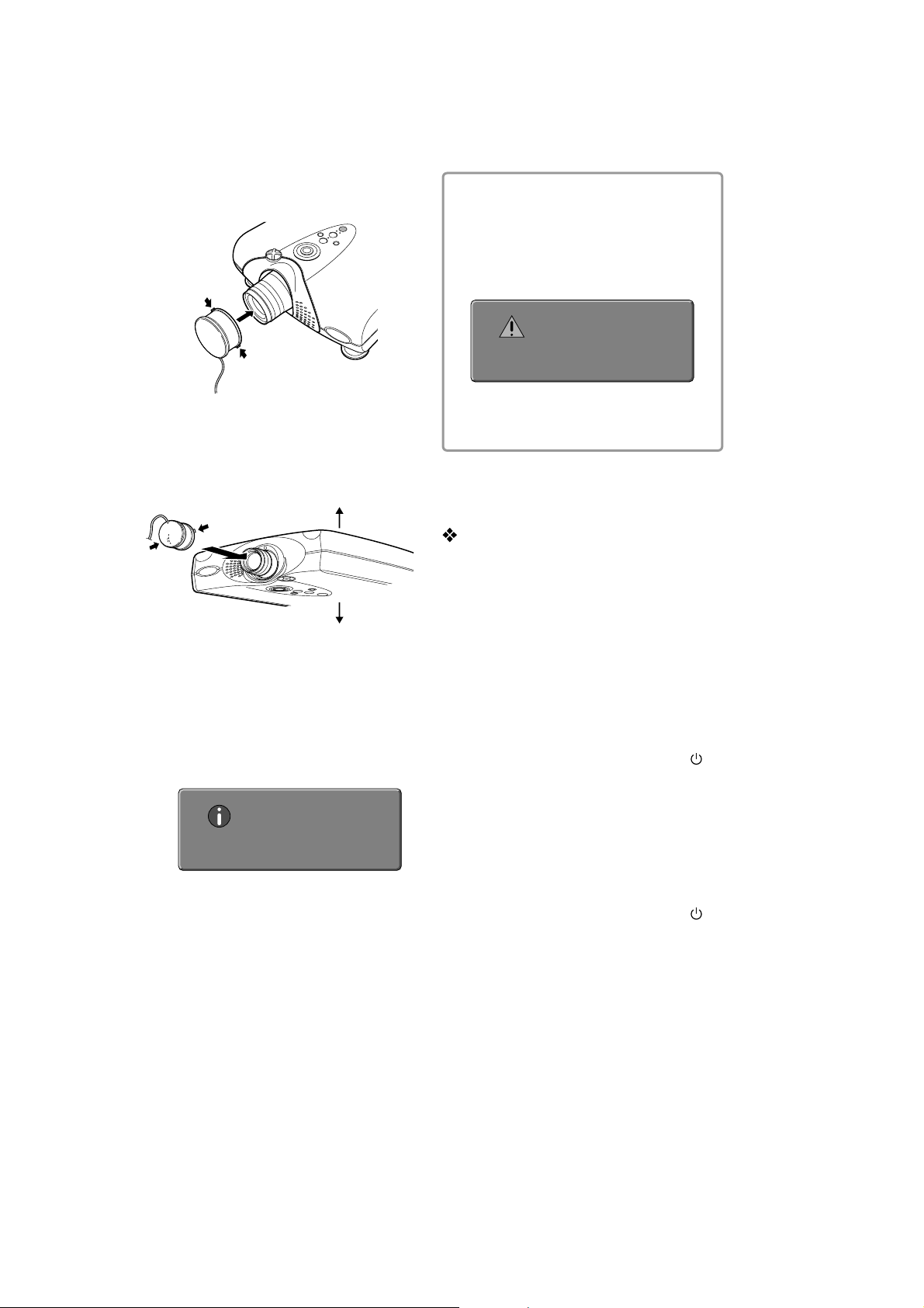
7. Fit the color temperature sensor onto the lens
and press the ENTER button. Color
temperature adjustment starts and the
projector’s WARNING and STANDBY
indicators begin flashing simultaneously.
When installed on a tabletop
Attach the color temperature
sensor so that the cable is to the
bottom side of the projector.
9. Press the ENTER button to return to the menu
and disconnect the cable of the color
temperature sensor from the projector.
Note:
If color temperature adjustment is not
correctly processed or if adjustment
processing is interrupted in course by
pressing the MENU button or for some other
reason, the below message appears on the
screen.
Quit
Press "Enter" to exit
Also, adjustment processing can be
interrupted by pressing the MENU button.
When installed on a ceiling
Bottom
To p
Attach the color temperature sensor so that the
cable is to the bottom side of the projector.
8. When the WARNING and STANDBY
indicators go out, color temperature
adjustment is complete. Adjustment takes
about 2 to 3 minutes. When the color
temperature sensor is detached from the lens,
the below message appears on the screen.
Complete
Press "Enter" to exit
10. Turn the lens shift knob until returning the lens
to the screen position you want to use.
Color Temperature Sensor
Protection
If no operations are performed for approximately 10
minutes from the moment color temperature
adjustment processing ends, power to the projector
shuts OFF automatically in order to protect the color
temperature sensor. If power is shut OFF to protect
the color temperature sensor, do the following.
If the WARNING indicator does not light
•
When color temperature adjustment ends
successfully and the sensor protection feature
trips, the projector goes on standby. As usual,
activate power by pressing either the ON
button on the remote control or the /I
button on the projector.
If the WARNING indicator lights
•
If color temperature adjustment does not end
successfully and the sensor protection feature
trips, the projector's WARNING and STANDBY
indicators light simultaneously to indicate the
error mode. Unplug the power cable and then
plug it back in. Then, press either the ON
button on the remote control or the /I
button on the projector to reactivate power.
16
Page 19

[B] 色温度補正
色温度の補正
ランプを交換したときなどに、色温度センサー
を使い色温度を補正することができます。
この補正手順の流れは、先ずセンサー自体を
初期化し、その後に本機の色温度を補正する
手順となっています。
本機の電源をONにしてから、ランプの明る
さが完全に安定するまで約10分かかります。
色温度の補正はランプの明るさが安定した後
に行ってください。
1. 色温度センサーのケーブル端子を本機の
RS-232C端子に接続します。
2.
電源投入後10秒以内に本体のLEFT、
ENTER、INPUTの3つのボタンを同時
に押してサービスモードに入ります。
または、サービスリモコンを使いRC5
コード"166363"を送りサービスモー
ドに入ります。
ENTERを押します。下記のメッセージ
画面が表示されます。
%NTER
ここで必ず ENTERボタンを押す前に、
下図のように色温度センサーを暗部にふ
せて、センサーの集光部に外からの光が
入らないようにしてください。
0ARTNO-:+!6
集光部
5. ENTERボタンを押すと、下記のメッセ
ージ画面が数秒間表示されます。色温度
センサー自体が初期化されます。
上下左右の矢印ボタンを使い、"色温度
3.
"の"色温度補正"を選択します。
方向ボタン
4.
のメッセージ画面が表示されます。
#(右)を押します。下記
%NTER
6. 次に、ランプからの光がレンズの中央を
通るように位置合わせを行います。これ
は正確な色温度補正を行うためです。ま
ず、レンズシフトノブを止まるまで左い
っぱいに回し、レンズを一番下側に下げ
ます。次に約5回転半だけ右に回し、レ
ンズを上げます。この状態でランプから
の光はレンズのほぼ中央を通るようにな
ります。
:この位置調整を行わないと、正確
な色温度補正が行われません。
17
Page 20

7. 色温度センサーを本機レンズ部分に取り
付け、 ENTERボタンを押します。色温
度の補正が開始され、本機のWARNING
ランプとSTANDBYランプが同時に点滅
します。
卓上設置の場合
本体に対して、センサーケー
ブルを必ず下側にして取り付
けてください。
天吊り設置の場合
:
色温度補正が正常に処理できなかっ
たり、色温度補正中に MENU ボタン
を押したり、何らかの理由で補正処
理が中断された場合は、下記のメッ
セージ画面が表示されます。
%NTER
またMENUボタンを押すことで、強
制的に補正処理を中断させることが
できます。
10.
レンズシフトノブを回して、ご使用のス
クリーン位置にレンズ位置を戻します。
色温度センサーの保護
本機は色温度センサーを保護するために、補
正処理が完了してから 無操作状態で約10分
経過すると、自動的に本機の電源が切れるよ
うになっています。
センサー保護のため電源が切れたときは、以
下の処置を行ってください。
本体に対して、センサーケーブルを必ず下側
にして取り付けてください。
8. WARNINGランプとSTANDBYランプの
点滅が消えると補正完了です。補正時間
は約2分かかります。色温度センサーを
取り外すと、下記のメッセージ画面が表
示されます。
%NTER
9. ENTERボタンを押してメニューに戻り、
色温度センサーのケーブル端子を外しま
す。
●
WARNINGインジケーターが点灯していな
い場合
色温度補正が正常に処理され、センサー保
護が働いた場合は、本機はスタンバイ状態
になります。
通常通り、リモコンの ONボタンまたは本
体の / I ボタンを押して電源を入れてく
ださい。
●
WARNINGインジケーターが点灯している
場合
色温度補正が正常に処理されず、センサー
保護が働いた場合は、本機のWARNINGラ
ンプとSTANDBYランプが同時に点灯しエ
ラーモードを表示します。
一度AC電源コードを抜き、再度差し込ん
でからリモコンの ONボタンまたは本体
の/I ボタンを押して電源を入れてくだ
さい。
18
Page 21
[C] Serial Number Installing Procedure
1. Necessary Equipments
• RS232C cable (Straight type: Female to Female)
• PC (Windows 200 or XP)
• Serial Number installing software "FwVpManf.exe" on the
PC
• A HyperTerminal Applet "VP_232C.hp" on the PC
2. Connections
Connect the RS232C cable to the RS232C ports of the
PC and the Projector.
3. Installing
1) Press the POWER button. And wait until the lamp lights
up completely.
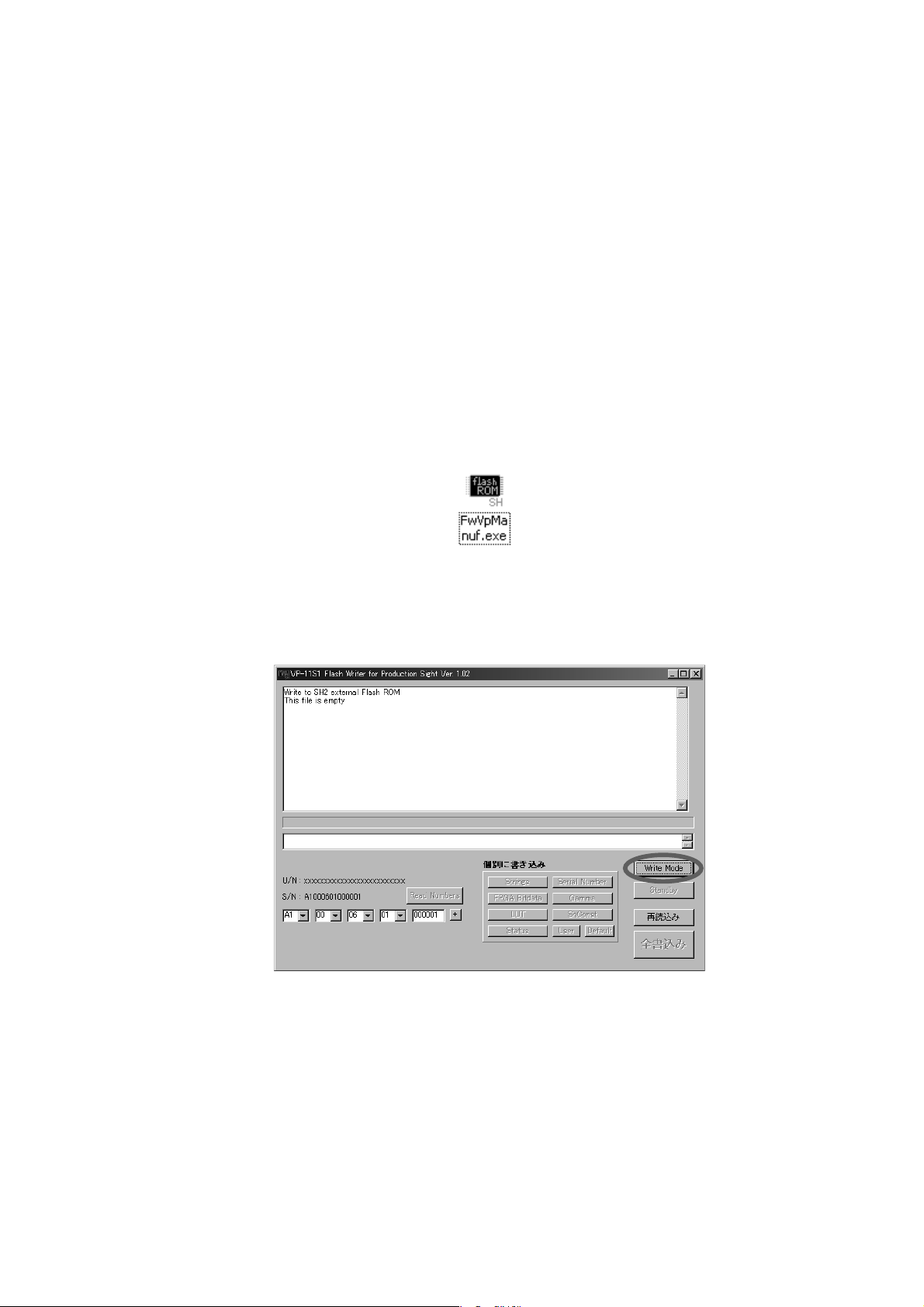
2) Open the "FwVpManf.exe" on the PC.
1. 準備するもの
• RS232Cケーブル (ストレート タイプ:メス⇔メス)
• PC (Windows200 もしくは XP)
• PCにインストールされたシリアルナンバー書込みツール
"FwVpManf.exe"
• PCにインストールされたハイパーターミナルアプレット
"VP_232C.hp"
2.
接続
RS232CケーブルをプロジェクターとPCのRS232Cポートに
接続します。
3. プログラムの起動と書込み、確認
1) POWERボタンをおして、ランプが点灯することを確認してくだ
さい。
2) "FwVpManf.exe"を開いてください。
3) Click the "Write Mode" button. And confirm the 3
indicators (ON, STANDBY and WARNING) on the
projector are flashing in sequence.
4) Click the "Standby" button. Make sure that the lamp is
turned off.
5) Input the serial number of the back panel of the target
projector.
3) "Write Mode"ボタンをクリックして 、プロジェクターの 3つのイ
ンジケーター
確認してください。
(ON, STANDBY, WARNING)が点滅することを
4) "Standby"ボタンをクリックし てください 、ランプが 消 灯します。
5) プロジェクターのバックパネルのシリアルナンバーを入力してく
ださい。
19
Page 22

6) Click "Serial Number" button to install.
6) "Serial Number"ボタンをクリックすると書き込まれます 。
7) Remove the main AC cable. Don’t power off by any other
means.
8) Connect the main AC cable and Press the POWER
button for confirmation.
9) Open the "VP_232C.hp" on the PC.
10) Input "@VER_SERIAL?" and press Enter key on the PC.
7) 電源ケーブルを抜いてください。
8) 確認のため、電源ケーブルを差し、プロジェクターをオンしてく
ださい。
9) "VP_232C.hp"を開いてください。
10) "@VER_SERIAL?"と入力し、PCのEnterキーを押してくださ
い。
20
Page 23

11) Confirm the serial number on the window and the
projector.
12) Turn off the projector.
11) プロジェクターとPCのウインドウのシリアルナンバーと確認し
てください。
12) プロジェクターの電源をオフします。
21
Page 24

[D] Confirmation procedure of software version
1. Necessary Equipments
A service remote controller that can output the RC5 code
"00 63 63". (The unit can adjust without a service remote
controller.)
2. Confirmation
1) Pressing the 3 buttons LEFT, ENTER, INPUT on the unit
within 10 seconds after turning on power or RC5 code
"00 63 63" is sent using service remote, and turn into
the service mode.
The Service Mode window is displayed.
2) With the direction buttons, up and down, select
"Contrast".
3) Press the "ENTER" button and the software version
information window is displayed.
1. 準備するもの
RC5コード"00 63 63"が出せるサービスリモコン
(サービスリモコンを使用せず、本体のみでも調整できます)
2.
確認
1) 電源投入後10秒以内に本体のLEFT, ENTER, INPUTの3つ
のボタンを同時に押してサービスモードに入ります。
Service Modeのウインドウが表示されます。
2) 上下の矢印ボタンを使い、"コントラ スト"を選 択します。
3) "ENTER"ボタンを押すとソフトウェア ー・ヴァージョン確 認 ウイ
ンドウが表示されます。
4) Confirm the software version.
The item(s) might be highlighted in red color at the
software version information window, when the software
combination didn’t true. In that case, please confirm
combination of software in Service Britain.
5) Press "ENTER" button to exit the software version
window.
6) Select "Service Exit" and press the "ENTER" button to
go the normal operation.
4) ソフトウェア ー ・ ヴァージョン を 確 認 します 。
赤色の文字で表示されている場合、ソフトウェアーの組合せが
正しく有りません。
ェアーの組み合わせを確認してください。
その場合は、サービスブリテンにてソフトウ
5) "ENTER"ボタンを押すとソフトウェアー ・ヴァー ジョン 確 認 ウ イ
ンドウ が 閉 じ ます 。
6) "Service Exit"を選択して"ENTER"ボタンを押すと通常動作
になります。
22
Page 25

[E] AD9888 Adjustment Method
[1] Necessaries
• Desktop Windows PC (for signal generator)
• Video card (It has to be filled the following features. ex.
NVIDA GeForce6600)
1. VGA/60Hz RGB signal can be generated.
2. 480P/60Hz, 720P/60Hz Component signal can be
generated.
**By way of example, this adjustment method mentions
about the example of use for the video card "NVIDA
GeForce6600".
• Windows PC(XP/2000) built in RS232C terminal (for
adjustment)
***Application software for AD adjustment (AtAdAdjEng.
exe) has to be installed to this PC already.
(Please note that you have to arrange 2 PC’s at least if
you perform this adjustment without the signal generator.
Application software for AD adjustment (AtAdAdjEng.exe)
can not run through the USB-RS232C converter. )
• RS232C cable (straight type : Female <-> Female)
• Test pattern data (White 80%, Black 0%, Yellow 100%,
Cyan 100%)
[E] A/DコンバータAD9888の調整方法
PCを信号発生器として用います。
[1] 調整に必要なもの
• 信号発生器として用いるPC
• Windows搭載PC(バージョンは使用するグラフィックカー
ドの要求による)
• グラフィックカード
RGB信号:VGA/60Hz RGB信号が出力可能な事
コンポーネント信号:480p・720p/60Hz信号が出力可能な
事
※一例としてNVIDIA GeForce6600搭載のグラフィックカ
ード使用例を示します。
• 調整用PC
RS-232C
調整用アプリケーション"AtAdAdj_1_08"がインストールさ
れている事
• RS-232Cケーブル(ストレート)
• テストパターン
White(80%)
Black(0%)
Yellow(100%)
Cyan(100%)
※テストパターン作成例を添付いたします。
端子が実装されたWindows 搭載PC
[2] Make out a test pattern
A test pattern is created using Windows standard
software (paint).
Start → programs → Accessories → Paint.
Fig 1 Screen of Paint
[2] テストパターンの作成
テストパターンはWindows標準ソフト(ペイント)を使い作
成します。
Windowsスタート → プログラム → アクセサリ → ペイン
トを起動します。
Fig 1. ペイント起動画面
The edit display of the color which clicks a color and is
shown in Fig2 in the upper part of a screen is started.
画面上部にある、色をクリックしてFig 2に示す色の編集画
面を立ち上げます。
23
Page 26

Fig 2. The edit screen of color
Fig 2. 色の編集画面
White(80%) : R=204 G=204 B=204
Black(0%) : R=0 G=0 B=0
Yellow(100%) : R=255 G=255 B=0
Cyan(100%) : R=0 G=255 B=255
After inputting a numerical value, OK is clicked and it
returns to the original screen.
It smears away by the color made after returning to the
screen of Fig1, and a test pattern is completed.
Please give a suitable name and save to a suitable
directory, respectively.
[3] Connections
VGA cable
VGAケーブル
Fig 2に示す色の編集画面にて赤緑青(RGB)に数値を入れて
色を作ります。各テストパターンに必要な数値は以下の通
りです。
White(80%) :R=204 G=204 B=204
Black(0%)
Yellow(100%)
Cyan(100%)
数値を入力後、OKをクリックして元の画面に戻ります。
:R=0 G=0 B=0
:R=255 G=255 B=0
:R=0 G=255 B=255
Fig 1の画面に戻った後に作った色で塗りつぶしテストパタ
ーンを完成させます。適当な名前をつけて適当なディレク
トリにそれぞれ保存してください。
[3] VP-15S1とPCの接続
Fig 3に調整時のVP-15S1とPCの接続を示します。
Desktop windows PC
with video card
for Signal generator
信号発生用PC
VP-15S1
RS232C straight cable
RS-232C
ケーブル
Fig 3. Connections / 接続図
Component cable
Connect to COMP1
コンポーネントケーブル
COMP1へ
上図に示す様にVP-15S1と接続します。コンポーネントケ
ーブルは
24
Windows PC
for adjustment
調整用PC
Comp1に接続します。
Page 27

[4] How to setup the desktop PC for signal generator
[4] 信号発生用PCの初期設定
1) After connecting all cables, press the power button on
the VP-15S1, and PC for signal generator and PC for
adjustment.
2) Change the input setting of VP-15S1 to the RGB input,
confirm that the screen of PC for signal generator
shows.
3) Change the RGB output resolution to VGA (640 x 480).
4) On the desktop of PC for signal generator, click the right
button of mouse and open the property for screen.
1) 接続後にVP-15S1、信号発生用PC、調整用PCをそれぞれ立
ち上げる。
VP-15S1をRGB入力に切り替 える。
2) 信号発生用PCの画面表示が出ることを確認します。
3) RGB出力解像度を(640 x 480)に変更する
4) デスクトップ 上 で 右 クリックをし 、画面のプロパティを開く。
Fig 4. Property for screen
5) Open the tab of setting, click the button of detailed
setting.
Fig 4.画面のプロパティ1
5)
設定タブを開き、詳細設定をクリックします 。
Fig 5. Property for screen 2
Fig 5. 画面のプロパティ2
25
Page 28

6) Open the tab of GeForce 6600.
6) GeForce 6600タブを開きます。タブを展 開 するとFig 5の詳
細設定画面になります。
Fig 6. Property of screen 3
7) Select "Screen resolution & refresh rates", Change the
Screen resolution as Fig 6 to 640 x 480, and change
the Screen refresh rate to 60Hz. After setting, click the
button of application.
Fig 7.Screen of confirmation 1
Fig 6. 画面のプロパティ3
7) Screen resolution & refresh rates
resolution
refresh rate
をFig 6の様に640 x 480に設定し、Screen
を60Hzにします 。設定後、適用をクリックしま す 。
Fig 7.確認画面1
を選択し、Screen
Fig 8.Screen of confirmation 2
8) After applying, the screen for confirmation shows as Fig
7 and Fig 8. Click the button of OK with both screens.
Then the signal of resolution 640 x 480 will output from
RGB output of PC.
[5] How to display the test pattern on screen
1) Run the Microsoft PAINT on the PC for signal generator.
2) Open the file of a test pattern. (By way of example, this
adjustment method mentions about the example of use
for the MS PAINT.)
確認画面2
Fig 8.
8)
適用後、Fig 7, Fig 8の様に確認画面が現れます。共にOKをク
リックし て 下さい 。
この状態でRGB出力端子から調整に必要な640 x480の解像
度が出力されます。
[5] テストパターンの表示
1) テストパターン作成に使用したペイントを立 ち 上げます 。
2) 先に作ったテストパターンのファイルを読み込みます。(本手順
書ではペイントを用いた例を示します)
26
Page 29

Fig 9.Screen of MS PAINT
Fig 9.ペイント画 面
3) To display the full screen of test pattern, click the "View"
of menu bar on the top of MS PAINT and select the
bitmap view. Then the test pattern shows on the full
screen.
[6] How to adjust
1) Adjustment of RGB
Double click the application file "AtAdAdjEng.exe" of the
folder AtAdAdjEnglish on the desktop.
3) 全画面テストパターン表示を行う為に上部にある表示をクリッ
クし 、ビットマップ表示を選択します。全画面にテストパター ン が
表示されます。
[6] 調整
1) RGBの調整
調整用PCにインストールした調整用アプリケーション
"AtAdAdj_1_08"
立ち上がります。
を立ち上げます。起動するとFig 10の画面が
Fig 10.Screen of AtAdAdjEng
2) Press the "SPACE" key on the keyboard of PC for
adjustment.
3) Confirms that the following message.
4) Input 80% White RGB signal with the PC for signal
generator.
Fig 10. AtAdAdj_1_08起動画面
調整用PCの"SPACE"キーを押し、調整を開始します (RGB入
力は自動的に切り替わります
)。
Fig 11のメッセ−ジを確認後、手順[5] テストパター ン の 表
示に従い、信号発生用
ます。全画面表示した信号を
PCでWhite(80%)のファイルを開き
RGB端子に入力し、調整用
PCの"SPACE"キーを押します。
27
Page 30

Fig 11.Screen of AtAdAdjEng
Fig 11. AtAdAdj_1_08起動画面
5) Press the "SPACE" key on the keyboard of PC for
adjustment.
6) Confirms that the following message.
7) Input 0% Black RGB signal with the PC for signal
generator.
Fig 12のメッセ−ジを確認後、手順[5] テストパター ン の 表
示に従い、信号発生用
ます。全画面表示した信号を
PCでBlack(0%)のファイルを開き
RGB端子に入力し、調整用
PCの"SPACE"キーを押します。
Fig 12.Screen of AtAdAdjEng
8) Press the "SPACE" key on the keyboard of PC for
adjustment.
9) Confirms that the following message.
10) Then the input of VP-15S1 changes RGB input to
COMP1 input automatically.
However, return the RGB input manually.
Fig 12.AtAdAdj_1_08起動画面
RGB調整終了後のFig 13に示す画面になります。
480p-RGB調整完了後、自動で480p-YUV調整に移行します。
セット本体の入力は自動でCOMP1に切り替 わりますが、一旦
RGB入力に戻してください。
28
Page 31

Fig 13.Screen of AtAdAdjEng
Fig 13. AtAdAdj_1_08起動画面
1 1) Adjustment of copmponent (480p)
Open the property of GeForce 6600 on the PC for signal
generator.
Fig 14.Screen of property for GeForce 6600
12) Select "nView Display Setting", and change the setting
of "Current display" to HDTV. Select 480p on the Device
Settings and click the application.
Then the output of PC for signal generator will change
the RGB output to the component output.
Change the input of COMP1 on the VP-15S1.
13) Input 100% saturation Yellow 480P/60Hz Component
signal with the PC for signal generator.
2) コンポーネント(480p)の調整
RGB出力を変更した時と同様に画面のプロパティから
GeForce6600のプロパティ画面にします。
Fig 14. 画面のプロパティ4
Fig 14
に示すnView Disply Settingを選択しCurrent
の設定をHDTVにします。同時にDevice Settings から
disply
出力解像度
す。
(480p)を選択します。選択後、適用をクリックしま
RGBから出力が停止し、コンポーネント端子からのみ信号が出
力されます。
ください 。
VP-15S1の入力をコンポーネント1に切り替えて
テストパターンの出力は、手順[5] テストパターンの表示に従い
行ってください。
RGB調整後の調整用アプリケーション"AtAdAdj_1_08"が
Fig 15を示していることを確認後、コンポーネント1に480p
Yellow(100%)
す。テストパターンの出力は、手順
従い行ってください。
を入力し、調整用PCの"SPACE"キーを押しま
[5] テストパターンの表示に
29
Page 32

Fig 15.Screen of AtAdAdjEng
Fig 15. AtAdAdj_1_08起動画面
14) Press the "SPACE" key on the keyboard of PC for
adjustment.
15) Confirms that the following message.
16) Input 100% saturation Cyan 480P/60Hz Component
signal with the PC for signal generator.
Fig 16のメッセ−ジを確認後、コンポーネントに480p
Cyan(100%)
す。テストパターンの出力は、手順
従い行ってください。
を入力し、調整用PCの"SPACE"キーを押しま
[5] テストパターンの表示に
17) Press the "SPACE" key on the keyboard of PC for
adjustment.
18) Confirms that the following message.
19) Input 0% Black 480P/60Hz Component signal with the
PC for signal generator.
Fig 16. AtAdAdj_1_08起動画面
Fig 17のメッセ−ジを確認後、コンポーネントに480p
Black(0%)
テストパターンの出力は、手順
行ってください。
を入力し、調整用PCの"SPACE"キーを押します。
[5] テストパターンの表示に従い
30
Page 33

20) Press the "SPACE" key on the keyboard of PC for
adjustment.
21) Confirms that the following message.
Fig 17. AtAdAdj_1_08起動画面
ここまでの作業で480pの調整が終了します。
22) Adjustment of copmponent (720p)
Open the property of GeForce 6600 on the PC for signal
generator.
( Fig 14.Screen of property for GeForce 6600 )
3) コンポーネント(720p)の調整
720pにてコンポーネント480pで行った調整と同様の調整
を行います。調整ソフトウェアは自動的に
480pの調整が終了
720pの調整に入ります。
( Fig 14. 画面のプロパティ4 )
31
Page 34

23) Select "nView Display Setting", and change the setting
of "Current display" to HDTV. Select 720p on the Device
Settings and click the application.
24) Input 100% saturation Yellow 720P/60Hz Component
signal with the PC for signal generator.
25) Press the SPACE key on the keyboard of PC for
adjustment.
26) Confirms that the following message.
27) Input 100% saturation Cyan 720P/60Hz Component
signal with the PC for signal generator.
28) Press the SPACE key on the keyboard of PC for
adjustment.
29) Confirms that the following message.
30) Input 0% Black 720P/60Hz Component signal with the
PC for signal generator.
画面のプロパティからGeForce6600のプロパティ画面Fig
に示すnView Disply Settingを選択しDevice Settings か
14
ら出力解像度
す。信号発生用
(720p)を選択します。選択後、適用をクリックしま
PCからコンポーネント720pが出力されます。
480p同様に調整用ソフトウェアの指示に従い、Yellow(100%)・
Cyan(100%)・Black(0%)と調整を進めてください。( 表示内容
は英文も参考にしてください。
)
.
.
.
.
.
.
.
.
.
.
.
.
.
.
.
.
.
.
.
.
.
.
.
.
.
.
.
.
.
.
.
.
.
.
.
.
.
.
.
.
.
32
Page 35

31) Press the SPACE key on the keyboard of PC for
adjustment.
32) Confirms that the following message.
.
.
.
.
.
.
.
.
.
.
.
.
.
全ての調整終了後にFig 18に示すメッセージが現れます。確認
をし て か ら セットの電源を落としてください。
33) Press Standby button on the projector.
34) Remove all connection cables.
<Trouble shooting against adjustment problem>
Adjustment problem mode:
An adjustment process will stop into an adjustment process.
Adjustment is not completed.
When the adjustment problem occurs into 480p-RGB
adjustment process
Press ESC key on the key board. Adjustment process
returns to an initial 480p-RGB adjustment process. Again,
please perform 480p-RGB adjustment process.
When the adjustment problem occurs into 480p-YUV
adjustment process
Press ESC key on the key board. Adjustment process
returns to an initial 480p-YUV adjustment process. Again,
Fig 18.終了メッセージ
以上で調整終了です。
33
Page 36

please perform 480p-YUV adjustment process.
When the adjustment problem occurs into 720p-YUV
adjustment process
Press ESC key on the key board. Adjustment process
returns to an initial 720-YUV adjustment process. Again,
please perform 720p-YUV adjustment process.
34
Page 37

7. TROUBLESHOOTING AND HINT
[1] Check list for Troubleshooting
Symptom 1 Symptom 2 Condition check Check Locations
1.
Is the voltage of 5V at P701-J302 (2 pin)? UN02, W013
↓
2.
No STANDBY
LED light up.
No Power
(Lamp does
not light)
The Power key
dose not work
Warnig LED
lights or Flashing
No Picture
Remote control does not work
Iris does not work
No change brightness of image.
No change Color of Focus
(Lens Shift sensor does not
work)
Is the voltage of 5V at P903-J329 (10 pin)? P701, W014
↓
3.
Is the voltage of 3.3V at P903-J329 (8 pin)? P701, W014
↓
Check 1-3 have no problem P903
1.
Is the voltage of 3.3V at P903-J329 (1 pin)? P701, W014
↓
Does voltage of P903-J329 (2 pin) change to 2.0V from 0V
2.
when push the power key?
↓
Check 1-2 have no problem P701, W014
Refer to The Error Status item and solution.
No image of MENU and PATTERN
No image of VIDEO input.
No image of S-VIDEO input.
No image of COMPONENT 1, 2 input.
No image of RGB input.
No image of HDMI 1, 2 input. P601, P801
1.
Is't Menu-Config.-Remote Control "Weird"? Set "Wireless"
↓
Is the voltage of 5V at P901-J330 (1 pin) and P902-J331
2.
(1 pin)?
↓
Is the pulse signal of 0V to 5V at P903-J329 (12 pin) when
3.
push the remote controller button?
↓
Is the pulse signal of 0V to 5V at P501-JL16 (10 pin) when
4.
push the remote controller button?
↓
5.
Is the voltage of 3.3V at P501-JL16 (7 pin)? P701, W012
↓
Is the pulse signal of 0V to 5V at P501-JL16 (9 pin) when
6.
push the remote controller button?
↓
Check 1-6 have no problem P701, W012
Refer to The Frow from Iris Control.
VP-15S1L is not this sensor.
P903
P701, W001, P101, P400,
UN04
P501, P801 "VIDEO" signal
line
P501, P801 "Y_S" and
"Y_C" signal line
P501, P801 "Y_COM#",
"CB#", CR#" signal input
P501, P801 "RGB_R(G, B,
H, V)"
P903, W015, W016
P903 "IR_SENSE", "IR_
FRONT" and "IR_REAR"
P701, W012, W014
P501
UN04, P701
(Don't remove the PCB of
UN04. Detection position
shifts.)
35
Page 38

Symptom 1 Symptom 2 Condition check Check Locations
Current 100mA or more
The voltage of 12V is not
outputted to TRIG1.
The voltage of 12V is not
outputted to TRIG2.
1. Is output current 100mA or less?
↓
When the lamp lights up, is the voltage of 3.3V at P501-
2.
JL16 (11 pin)
↓
Check 1-2 have no problem P501
1. Is output current 100mA or less?
↓
2. Are the Menu setup and selection Aspect setup correctly? Setup the menu.
↓
3. Is the voltage of 3.3V at P501-JL16 (12 pin) P701, W012
↓
Check 1-3 have no problem P501
is not accepted by
specification.
P701, W012
Current 100mA or more
is not accepted by
specification.
36
Page 39

[2] The flow from IRIS Control
1) Refer to the schematic diagram of P201-2/2.
2) Q262 and Q264 is 74VHC123AFT "Mono stable multi vibrator".
Q263 and Q265 is BA6951FS "DC motor driver".
3) Refer to the following timing chart.
4) IRIS1 or IRIS2 = "L" level (0V) ------- Iris is narrow.
IRIS1 or IRIS2 = "H" level (3.3V) ---- Iris is Wide.
5) The iris mode in menu vs. Iris pattern.
Iris Mode Contrast Brightness Lens Iris Illumination Iris
1 High Low Narrow Narrow
2 Middle Middle Narrow Wide
3 Low High Wide Wide
37
Page 40

[3] The flow from turn on the projector to the picture projection
1) Turn on the projector.
2) P701-J302 (3 pin) "PWR-CTR" become to "H" level (3.3V).
3) P701-J301, P101-J005, P201-J201 and P601-JE05 are raised to true voltage.
PCB - Connector Pin No. Voltage (V) PCB - Connector Pin No. Voltage (V)
P701 – J302
Connectors Location
1 0 (GND)
2 13.3 2 13.3
3 -6.1 3 0 (GND)
4 0 (GND) 4 13.3
5 0 (GND) 5 0 (GND)
6 6.1 6 13.3
7 0 (GND) 7 0 (GND)
8 3.5 8 13.3
9 0 (GND) 9 0 (GND)
10 3.5 10 13.3
11 0 (GND) 11 0 (GND)
12 2.5 12 13.3
13 0 (GND)
14 1.2 2 0 (GND)
15 1.2 3 6.1
16 0 (GND)
P101 – J005
P201 – J201
P601 – JE05
1 0 (GND)
1 13.3
1 6.1
2 0 (GND)
3 3.5
4 0 (GND)
J301
On
P601
J301
J005
J201
4) Configuration of the main u-P, CPLD, FPGA and GF9351 on P701 and P801.
5) P101-R073 "PWR_GOOD" becomes to "H" level (3.3V) and D001 (Yellow LED) lights up.
38
Page 41

R049
"LAMPLIT"
R048 and D002
"ASIC_REDAY"
R073 And D001
"PWR_GOOD"
6) The drive signal (3 phase motor drive) output from P101-J008
The color wheel starts.
7) P101-J011 (1 pin) "SCI" of the control signal for the lamp ignition become to "H" level (5V).
The lamp lights up.
8) P101-J011 (3 pin) "FLAG_OUT" become to "L" level (0V)
When "FLAG_OUT" don’t become to "L" level (0V), it returns to 5). After repeating 3 times, Warning LED lights up.
9) "FLAG_OUT" signal go to SSB PCB board from P101-J012 (3 pin).
10) P101-R049 "LAMPLIT" become to "L" level (0V).
11) P101-R048 "ASIC_READY" becomes to "H" level (3.3V) and D002 (Green LED) lights up.
12) A picture is projected.
39
Page 42

[4] DMD [1080p] Image Quality Specification
1 Error definitions
1.1 Dark Blemish
A blemish is an obstruction or reflection of light.
This is dark visibility on light screen in the active area.
This is any form and size.
1.2 Light Blemish
A blemish is an obstruction or reflection of light.
This is light visibility on dark screen in the active area.
This is any form and size.
1.3 Dark Pixel
A dark pixel is a mirror that is stuck in the OFF position.
This is visible that is dark square pixel on light screen in
the active area.
Major Dark Blemish
Major Dark Blemish
Blue 60
Blue 60
Minor Dark Blemish
Minor Dark Blemish
White
White
Major Light Blemish
Major Light Blemish
Gray 10
Gray 10
Minor Light Blemish
Minor Light Blemish
Black
Black
WhiteWhite
1.4 Light Pixel
A light pixel is a mirror that is stuck in the ON position.
This is visible that is light square pixel on dark screen in
the active area.
1.5 Unstable Pixel
An unstable pixel is a mirror that does not operate.
This appears to be flickering asynchronously with image.
Flickering pixelFlickering pixel
1.6 Border Defect
Border defect is pixel defect or Blemish in border area
(see Fig. 2.2).
Gray 10Gray 10
Any other ScreenAny other Screen
Any ScreenAny Screen
40
Page 43

2 Screen image
2.1 Active Area
The Active area is the active pixel area on image screen.
This is visible white area when input signal is all white.
2.2 Border Area
The border is described as the area outside of the active area.
This is visible black outside white image when input signal is all white.
(See Fig. 2.2)
60inch(152cm)
Border area
Border area
Around 4inch(10cm)
Around 4inch(10cm)
Active area
Fig. 2.2 Border areaFig. 2.2 Border area
3 Test conditions and Specifications
3.1 Image size
The diagonal size of the projection image on the screen shall be at minimum 60 inches (152cm).
3.2 Viewing distance
The projected image shall be inspected from 8 foot (2.4m) minimum viewing distance.
3.3 Focus
Projection must be properly focused on DMD array as shown on the screen.
3.4 Screen image
Menu setting of the VP-15S1 should be initial "Optics check" in "service mode".
3.5 Hints
All error that scratches on DMD and so on shall be checked the projected image on the screen.
3.6 Image quality specification test criteria
Test
1 Major Dark Blemish Blue 60
2 Major Light Blemish Gray 10
3 Border Defects Any Screen Acceptable
4 Dark Pixel White
5 Light Pixel Gray 10 No pixels brighter than Gray 10 in Active Area.
6 Minor Blemishes
7 Unstable Pixel Any Screen No unstable pixels
screen
(Note 4)
White
Black
Maximum 6 visible blemishes darker then Blue 60.
No Blemish longer then 1 inch at 60 inches.
Maximum 6 visible blemishes darker then Gray 10.
No Blemish longer then 1 inch at 60 inches.
Maximum 8 dark pixels allowed in Active Area.
No adjacent dark pixels
Acceptable
Acceptance criteria
Note:
1. Projected blemish numbers count shadow of the artifact in addition to the artifact itself.
2. Border defects are bright blemishes or light pixel in the non-active area then may be visible.
41
Page 44

3. Screen select for remote controller
Component 1 Input video signal
Component 2 Lens Iris on/off
S-Video Illumination Iris on/off
Video Raster (Black)
RGB Raster (White)
Theater Red
Standard Green
Dynamic Blue
Info. Resolution
Full Horizontal Staircase
Normal Vertical Staircase
Cinema Color Bars
Through Horizontal Ramp
Zoom Blue 90
HDMI 1 Gray 5
Pattern Gray 10
V Mute Gray 30
Black level Blue 60
VCR Mode Gray 6
HDMI 2 Gray 1
42
Page 45

7. TROUBLESHOOTING AND HINT
[1] CHECK LIST FOR TROUBLESHOOTING 対処方法
症状 1症状 2 確認手順 対象箇所
1. P701-J302 (2 pin)に5Vの電圧が有りますか? UN02, W013
↓
STANDBY LED
しない
電源が入らない
(ランプが点灯し
ない
)
Power
キーを受付けない
STANDBY LEDが点灯し
たまま
Warnig LED
は点滅する
画面が表示されない
リモコンが効かない
アイリスが動作しない
画面の明るさが変わらない
Focusの色が変わらない
(
Lens Shiftセンサーが効かない)
が点灯
が点灯もしく
2. P903-J329 (10 pin)に5Vの電圧が有りますか? P701, W014
↓
3. P903-J329 (8 pin)に3.3Vの電圧が有りますか? P701, W014
↓
確認1〜3まで
OK P903
1. P903-J329 (1 pin)に3.3Vの電圧が有りますか? P701, W014
↓
Power
2.
キーを押した時、P903-J329 (2 pin)が0Vから
2.0Vに変化しますか?
↓
確認1〜2まで
OK P701, W014
P903
Error Status 参照
MENUや PATTERNが表示されない
入力が表示されない
VIDEO
S-VIDEO
入力が表示されない
P701, W001, P101,
P400, UN04
P501, P801 "VIDEO"
signal line
P501, P801 "Y_S" and
"Y_C" signal line
P501, P801 "Y_COM#",
COMPONENT 1, 2
入力が表示されない
"CB#", CR#" signal
input
入力が表示されない
RGB
HDMI 1, 2
メニュー-初期設定-リモートコントロールが"ワイヤー
1.
ド
"に設定されていませんか?
P901-J330 (1 pin)
2.
ますか
リモコンのボタンを押した時、 P903-J329 (12 pin)に
3.
0Vから5Vまでのパルスが有りますか?
リモコンのボタンを押した時、P501-JL16 (10 pin)に
4.
0Vから5Vまでのパルスが有りますか?
入力が表示されない P601, P801
↓
と P902-J331 (1 pin)に3.3Vが有り
?
↓
↓
↓
P501, P801 "RGB_R(G,
B, H, V)"
ワイヤレスにする
P903, W015, W016
P903 "IR_SENSE",
"IR_FRONT" and
"IR_REAR"
P701, W012, W014
5. P501-JL16 (7 pin)に3.3Vの電圧が有りますか? P701, W012
↓
リモコンのボタンを押した時、P501-JL16 (9 pin)に0Vか
6.
ら
5Vまでのパルスが有りますか?
↓
確認1〜6まで
OK P701, W012
P501
Frow from Iris Control 参照
UN04, P701
VP-15S1L
はセンサーが有りません
(UN04
ない事、検出位置がズレ
ます。
の基板ははずさ
)
43
Page 46

症状 1症状 2 確認手順 対象箇所
仕様で
せません
P701, W012
仕様で
せません
Setup the menu.
TRIG.1(トリガー1端子)に12Vの電圧が出
力されない
The voltage of 12V is not outputted to
TRIG2.
1. 出力電流は100mA以下ですか?
↓
ランプが点灯している時、P501-JL16 (11 pin)に3.3Vの
2.
電圧が有りますか
出力電流は100mA以下ですか?
1.
メニューの設定と選択しているアスペクトは正しく設定
2.
されていますか
?
確認1〜2まで
?
↓
OK P501
↓
↓
3. P501-JL16 (12 pin)に3.3Vの電圧が有りますか? P701, W012
↓
確認1〜3まで
OK P501
100mA以上は流
100mA以上は流
44
Page 47

[2] アイリス 制御の仕様
1) 回路図を確認ください。P201-2/2.
2) Q262
Q263とQ265はBA6951FS "DC motor driver"です。
3)
とQ264は74VHC123AFT "Mono stable multi vibrator" です。
下記のタイミングチャートを確認ください。
4) IRIS1とIRIS2は"L"レベル (0V)の時 ------- アイリス は 絞って います 。
IRIS1とIRIS2は"H"レベル (3.3V)の時 ---- アイリスは開いています。
5) メニューで の ア イリス設定値とアイリスの状態
アイリス設
定値
1
2
3
コントラスト 明るさ
高い 低い 狭い 狭い
中間 中間 狭い 開放
低い 高い 開放 開放
レンズ側
アイリス
照明側
アイリス
45
Page 48

[3] 電源ONから映像投影までのフロー
1) プロジェクターをONする。
2) P701-J302 (3 ピン) "PWR-CTRL"が"H"レベル(3.3V)になる。
3) P701-J301, P101-J005, P201-J201, P601-JE05に各電源が立上る。
PCB–コネクター ピン 電圧 (V) PCB-コネクター ピン 電圧 (V)
P701 – J302
1 0 (GND)
2 13.3 2 13.3
3 -6.1 3 0 (GND)
4 0 (GND) 4 13.3
5 0 (GND) 5 0 (GND)
6 6.1 6 13.3
7 0 (GND) 7 0 (GND)
8 3.5 8 13.3
9 0 (GND) 9 0 (GND)
10 3.5 10 13.3
11 0 (GND) 11 0 (GND)
12 2.5 12 13.3
13 0 (GND)
14 1.2 2 0 (GND)
15 1.2 3 6.1
16 0 (GND)
P101 – J005
P201 – J201
P601 – JE05
1 0 (GND)
1 13.3
1 6.1
2 0 (GND)
3 3.5
4 0 (GND)
J005
J301
On
P601
J301
J201
コネクターの位置
4) 各デバイスを初期化します。(メインマイコン、CPLD, FPGA, GF9351)
5) P101-R073 "PWR_GOOD"
が"H"レベル(3.3V)になり、D001(黄色のLED)点灯します。
46
Page 49

R049
"LAMPLIT"
R048 and D002
"ASIC_REDAY"
R073 And D001
"PWR_GOOD"
6) 3相モー タ のドライブが P101-J008から出力され、カラーホイールが 回 転します。
7) P101-J011(1 ピン) "SCI"が"H"レベル(5V)となり、ランプが 点灯します。
8) P101-J011 (3 ピン) "FLAG_OUT"が"L"レベル(0V)になります。
"FLAG_OUT"が"L"レベル(0V)にならない場合、5)にもどる、3回くり返し た 後 Warning LEDが点灯する。
9) "FLAG_OUT"信号はP101-J012 (3 ピン)からSSB基板へ送られる。
10) P101-R049 "LAMPLIT"が"L"レベル(0V)になる。
11) P101-R048 "ASIC_READY"が"H"レベル(3.3V)になり、D002(緑色のLED)が点灯する。
12) 映像が投影される。
47
Page 50

[4] DMD 検査基準
1 エラーの種類
1.1 Dark Blemish(ダーク・ブレミッシュ)
ホコリ、キズなどによる光りの障害・反射
明るい画面で暗くなって見える物
形、大きさは様々な物がある
1.2 Light Blemish(ライト・ブレミッシュ)
ホコリ、キズなどによる光りの障害・反射
暗い画面で明るくなって見える物
形、大きさは様々な物がある
1.3 Dark Pixel (黒点)
ミラーがオフ・ポジションに固定された物
明るい画面で黒い正方形(画素)として見える
Major Dark Blemish
Major Dark Blemish
Blue 60
Blue 60
Minor Dark Blemish
Minor Dark Blemish
White
White
Major Light Blemish
Major Light Blemish
Gray 10
Gray 10
Minor Light Blemish
Minor Light Blemish
Black
Black
WhiteWhite
1.4 Light Pixel (輝点)
ミラーがオン・ポジションに固定された物
暗い画面で白い正方形(画素)として見える。
1.5 Unstable Pixel (不安定画素)
ミラーが制御されず動いている物
ある静止画面を見た時、画素が固定されず明暗が動いて見
える物。
明るさが変わる明るさが変わる
1.6 Border Defect(ボーダー・ディフェクト)
ボーダー・エリア(2.2章)にあるブレミッシュ及び画素欠陥
Gray 10Gray 10
Any ScreenAny Screen
Any ScreenAny Screen
48
Page 51

2 画面
2.1 Active Area (アクティブ・エリア)
画素が動作する部分
白画面を投影した時、白くなる部分
2.2 Border Area(ボーダー・エリア)
アクティブ・エリアの外周部分、60 inchの画面で数cmの範囲
黒画面を投影した時、Active Areaの外枠で明るさが少し異なる部分
図2.2参照
60inch (152cm)
ボーダー・エリア
ボーダー・エリア
周囲 数cm
周囲 数cm
アクティブ・エリア
図2.2 ボーダー・エリア図2.2 ボーダー・エリア
3 テスト環境・基準
3.1 投影サイズ
スクリーン上の投影サイズは対角 60 inch (152 cm) 以上にしてください。
3.2 確認距離
スクリーンから2.4 m (8 feet) 以上離れてテストしてください。
3.3 フォーカス
フォーカスをDMDに合わせた状態でテストしてください。
3.4 表示画面は"Service Mode"内の"Optics check"で行う。
パターン変更は表3.1 表示パターン−リモコン対比 を参照ください。
3.5 確認方法
全てのエラーについて投影したスクリーンにてテストしてください。
DMDに付いたキズ等も投影したスクリーンにて判定してください。
3.6 試験項目
60 inch(152 cm)60 inch(152 cm)
検査項目 パターン 検査内容
1 Major Dark Blemish Blue 60
2 Major Light Blemish Gray 10
Active Area
60inch
Active Area
60inch
内に、Blue 60よりも暗いブレミッシュは6個までOK
の画面で1inch(2.5cm)より大きいブレミッシュが無い事
内に、Gray 10よりも明るいブレミッシュは6個までOK
の画面で1inch(2.5cm)より大きいブレミッシュが無い事
3 Border Defects Any Screen Active area外のピクセル欠陥、ブレミッシュ等はOKとする。
4 Dark Pixel White
Active Area
隣り合う画素が無いこと
内に、暗い画素欠陥は8個までOK
5 Light Pixel Gray 10 Active Area内にGray 10より明るい画素欠陥がない事
6 Minor Blemishes
White
Black
全てOKとします。
7 Unstable Pixel Any Screen 不安定なピクセルが無いこと
49
Page 52

表3.1 表示パターン−リモコン対比
Service Mode内Optics Checkのリモコンキー−表示パターン対応表
Component 1 Input video signal
Component 2 Lens Iris on/off
S-Video Illumination Iris on/off
Video Raster (Black)
RGB Raster (White)
Theater Red
Standard Green
Dynamic Blue
Info. Resolution
Full Horizontal Staircase
Normal Vertical Staircase
Cinema Color Bars
Through Horizontal Ramp
Zoom Blue 90
HDMI 1 Gray 5
Pattern Gray 10
V Mute Gray 30
Black level Blue 60
VCR Mode Gray 6
HDMI 2 Gray 1
50
Page 53

[5] The DC voltage value which was measured
PWB : P101
Input terminal : VIDEO
Input signal : SMPTE Color Bar
Equipment : Tester (DC Voltage mesure mode)
POS. NO. PIN NO. VOLTAGE DEVICE
1 5.0
J006
J009
J005
J011
J012
Q011
Q012
D001
Q013
Q014
Q016
D002
2 5.0
3 5.0
4 0.0
1 1.2
2 0.5
3 0.0
1 0.0
2 13.3
3 0.0
4 13.3
5 0.0
6 13.3
7 0.0
8 13.3
9 0.0
10 13.3
11 0.0
12 13.3
1 1.6
2 0.0
3 0.2
4 0.0
1 0.0
2 0.0
3 0.1
4 0.0
1 0.0
2 3.5
3 0.0
4 3.1
5 3.3
1 0.0
2 3.1
3 0.0
4 3.1
5 3.3
Anode 2.0
Cathode 0.0
1 0.0
2 3.3
3 0.0
4 3.2
5 3.3
1 3.3
2 3.3
3 5.0
4 3.3
5 3.3
6 5.0
1 0.0
2 3.3
3 0.0
4 3.1
5 3.3
Anode 2.0
Cathode 0.0
74LVC1G07DCKR
74LVC1G17DCKR
SML-010YT
74LVC1G17DCKR
HN1K05FU
74LVC1G17DCKR
SML010MT
POS. NO. PIN NO. VOLTAGE DEVICE
1 1.6
2 3.2
3 0.0
4 3.1
5 3.2
6 0.0
7 1.3
Q007
Q008
Q005
QA05
C096
C097
C199
CB99
J008
D11
8 1.3
9 1.3
10 2.5
11 0.0
12 3.2
13 3.2
14 3.2
15 3.2
16 1.9
1 1.3
2 0.0
3 1.2
4 2.5
5 1.2
6 0.0
7 0.0
8 2.5
9 0.0
10 0.0
11 2.5
12 1.2
13 0.0
14 1.2
15 1.2
16 2.5
1 1.5
2 1.5
3 0.7
4 0.0
5 0.7
6 0.7
7 5.0
8 0.0
9 5.0
10 5.0
1 1.5
2 1.5
3 0.7
4 0.0
5 0.7
6 0.7
7 5.0
8 0.0
9 5.0
10 5.0
+ 13.3
- 0.0
+ 13.3
- 0.0
+ 13.3
- 0.0
+ 13.3
- 0.0
1 5.7
2 5.7
3 5.7
4 5.7
1 13.3
3 0.0
ICS650-41
PI49FCT20802
TPS51100
TPS51100
Tantal Cap.
Tantal Cap.
Tantal Cap.
Tantal Cap.
BAT54SWT12 5.7
51
Page 54

PWB : P101
POS. NO. PIN NO. VOLTAGE DEVICE
1 13.3
D12
D13
D14
Q030
Q031
Q032
Q035
3 0.0
1 13.3
3 0.0
1 13.3
3 0.0
1 0.0
2 0.0
3 3.3
4 0.0
5 3.3
6 3.3
7 0.0
8 3.3
1 0.0
2 3.2
3 0.0
4 3.3
5 3.3
1 1.1
2 1.1
3 0.0
4 1.6
5 5.0
1 0.0
2 0.2
3 0.0
4 0.0
5 3.3
BAT54SWT12 5.7
BAT54SWT12 5.7
BAT54SWT12 5.7
AT24C08A
74LVC1G17DCKR
74LVC1G17DCKR
74LVC1G17DCKR
PWB : P201
Menu : Display Installation Front
Menu : Picture Adjust Lamp Mode Normal
Equipment : Tester (DC Voltage mesure mode)
POS. NO. PIN NO. VOLTAGE DEVICE
1 13.3
J201
J202
J203
J204
J205
J224
J223
J221
J220
J206
J207
J208
J209
J210
2 0.0
3 6.1
1 0.0
2 0.0
3 0.0
4 0.0
5 3.5
6 0.0
7 0.0
8 0.0
9 0.0
10 0.0
11 0.0
12 0.0
1 0.0
2 0.0
1 0.0
2 0.0
1 0.0
2 0.0
1 1.2
2 0.8
3 0.0
1 1.2
2 0.5
3 0.0
1 5.7
2 5.7
3 5.7
4 5.7
5 5.7
6 5.7
7 5.7
8 5.7
1 5.7
2 5.7
3 5.7
4 5.7
1 9.3
2 0.0
3 0.0
1 0.1
2 0.0
3 10.3
1 0.1
2 0.0
3 6.8
1 0.1
2 0.0
3 8.7
1 0.0
2 0.0
3 8.8
52
Page 55

PWB : P201
POS. NO. PIN NO. VOLTAGE DEVICE
1 3.5
2 6.0
3 6.0
4 3.5
5 0.0
6 0.0
Q201
Q202
Q203
Q204
Q205
Q206
Q207
Q260
7 0.0
8 0.0
9 0.0
10 0.0
11 0.0
12 0.0
13 0.0
14 6.1
Base 3.5
Emitter 0.0
Base 0.0
Emitter 0.0
1 0.0
2 0.0
3 0.0
4 6.1
5 6.1
6 6.1
1 0.0
2 5.5
3 6.1
4 6.1
5 5.8
6 0.0
7 6.1
8 0.0
9 0.0
10 6.1
11 5.8
12 5.8
13 5.7
14 0.0
15 6.1
16 6.1
Base 5.5
Emitter 0.0
Base 2.3
Emitter 0.0
1 0.0
2 1.9
3 0.0
4 0.0
5 0.0
6 13.3
7 0.0
8 0.0
9 0.0
10 0.0
11 0.0
12 6.1
13 6.1
14 0.0
15 0.0
16 0.0
TC74VHCT08AFT
RN1107Collector 0.0
RN1107Collector 6.1
UMD9NTR
BU4015BF-E2
RN1107Collector 0.0
RN1107Collector 0.0
BA6951FS-E2
POS. NO. PIN NO. VOLTAGE DEVICE
1 0.5
2 3.2
3 0.8
Q270
Q210
Q211
Q212
Q213
Q214
Q220
Q221
Q222
Q223
Q224
D280
4 0.0
5 6.1
6 5.3
7 2.0
8 0.0
1 5.7
2 13.3
3 0.0
4 10.0
5 1.2
1 0.0
2 6.0
3 9.9
4 10.0
5 0.0
6 0.0
1 0.0
2 0.0
3 1.2
4 10.0
5 9.9
6 9.9
1 0.0
2 0.0
3 1.2
4 13.3
5 13.3
6 13.3
1 0.0
2 0.0
3 1.2
4 13.3
5 13.3
6 13.3
1 5.7
2 13.3
3 0.0
4 11.0
5 1.2
1 0.0
2 6.0
3 11.0
4 11.0
5 0.0
6 0.0
1 0.0
2 0.0
3 1.2
4 11.0
5 11.0
6 11.0
1 0.0
2 0.0
3 1.2
4 13.3
5 13.3
6 13.3
1 0.0
2 0.0
3 1.2
4 13.3
5 13.3
6 13.3
1 0.0
2 0.0
3 0.1
NJM2903M
BA00ASFP
UMD9NTR
UMD9NTR
UMD9NTR
UMD9NTR
BA00ASFP
UMD9NTR
UMD9NTR
UMD9NTR
UMD9NTR
1SS361
53
Page 56

PWB : P201
POS. NO. PIN NO. VOLTAGE DEVICE
1 5.8
2 13.3
Q230
Q231
Q232
Q233
Q234
Q240
Q241
Q242
Q243
Q244
D281
Q250
3 0.0
4 7.6
5 1.2
1 0.0
2 6.0
3 7.6
4 7.6
5 0.0
6 0.0
1 0.0
2 0.0
3 1.2
4 7.6
5 7.5
6 7.5
1 0.0
2 0.0
3 1.2
4 13.3
5 13.3
6 13.3
1 0.0
2 0.0
3 1.2
4 13.3
5 13.3
6 13.3
1 5.5
2 13.3
3 0.0
4 9.4
5 1.2
1 0.0
2 6.0
3 9.4
4 9.4
5 0.0
6 0.0
1 0.0
2 0.0
3 1.2
4 9.4
5 9.4
6 9.4
1 0.0
2 0.0
3 1.2
4 13.3
5 13.3
6 13.3
1 0.0
2 0.0
3 1.2
4 13.3
5 13.3
6 13.3
1 0.1
3 0.1
1 5.8
2 13.3
3 0.0
4 9.5
5 1.2
BA00ASFP
UMD9NTR
UMD9NTR
UMD9NTR
UMD9NTR
BA00ASFP
UMD9NTR
UMD9NTR
UMD9NTR
UMD9NTR
1SS3612 0.0
BA00ASFP
POS. NO. PIN NO. VOLTAGE DEVICE
1 0.0
2 6.0
Q251
Q252
Q253
Q254
D282
3 9.5
4 9.5
5 0.0
6 0.0
1 0.0
2 0.0
3 1.2
4 9.5
5 9.5
6 9.5
1 0.0
2 0.0
3 1.2
4 13.3
5 13.3
6 13.3
1 0.0
2 0.0
3 1.2
4 13.3
5 13.3
6 13.3
1 0.0
3 0.0
UMD9NTR
UMD9NTR
UMD9NTR
UMD9NTR
1SS3612 0.0
54
Page 57

PWB : P601
Input terminal : HDMI 1
Input signal : SMPTE Color Bar 1080p/60Hz
Equipment : Tester (DC Voltage mesure mode)
POS. NO. PIN NO. VOLTAGE DEVICE
1 6.1
JE05
JE06
QE01
2 0.0
3 3.5
4 0.0
1 0.0
2 0.0
3 0.0
1 0.9
2 0.9
3 0.9
4 0.0
5 1.6
6 3.3
7 1.0
8 0.9
9 1.0
10 1.0
11 0.0
12 1.8
13 0.0
14 0.0
15 0.0
16 0.0
17 0.0
18 3.3
19 2.8
20 3.2
21 3.3
22 1.7
23 0.0
24 1.8
25 1.8
26 3.4
27 3.4
28 5.0
29 5.0
30 0.1
31 0.0
32 3.3
33 5.0
34 5.0
35 5.0
36 0.0
37 1.8
38 3.3
39 3.0
40 3.0
41 0.0
42 3.3
43 3.0
44 3.0
45 0.0
46 3.3
47 3.0
48 3.0
49 0.0
50 3.3
51 3.0
52 3.0
53 0.0
54 1.8
55 0.1
56 3.3
SII9135
POS. NO. PIN NO. VOLTAGE DEVICE
57 3.3
58 3.3
59 0.0
60 3.3
61 3.3
62 3.3
63 0.0
64 3.3
65 3.3
66 3.3
67 0.0
68 3.3
69 3.3
70 3.3
71 0.0
72 1.8
73 0.0
74 3.3
75 3.3
76 3.3
77 0.0
78 0.0
79 0.0
80 1.8
81 0.0
82 1.8
83 0.0
84 0.0
85 0.0
86 0.0
87 0.0
88 3.3
89 0.0
90 0.0
QE01
91 1.8
92 1.8
93 0.0
94 1.6
95 1.8
96 3.3
97 3.3
98 0.0
99 0.0
100 3.4
101 3.3
102 3.3
103 0.0
104 3.3
105 0.0
106 0.0
107 1.8
108 2.4
109 1.0
110 1.0
111 0.9
112 0.0
113 3.3
114 0.9
115 1.0
116 1.0
117 1.0
118 0.0
119 1.8
120 0.0
121 0.0
122 0.0
123 0.0
124 0.0
125 3.3
SII9135
55
Page 58

PWB : P601
POS. NO. PIN NO. VOLTAGE DEVICE
126 1.2
127 0.1
128 1.4
129 2.1
130 0.0
131 1.8
132 1.2
133 1.1
134 1.2
QE01
DE09
DE08
QE05
QE23
DE01
QE03
QE06
DE07
QE11
QE24
DE10
DE11
QE21
QE26
135 1.3
136 0.0
137 3.3
138 0.0
139 0.0
140 0.0
141 0.0
142 0.0
143 1.8
144 2.5
1 5.0
3 0.0
1 5.0
3 0.0
Base 0.0
Emitter 0.0
Base 0.7
Emitter 0.0
1 5.0
3 5.0
1 5.0
2 5.0
3 5.0
4 5.0
5 5.0
6 5.0
1 0.0
2 0.0
3 0.0
4 0.0
5 5.0
6 5.0
7 5.0
8 5.0
1 5.0
3 0.1
Base 0.1
Emitter 0.0
Base 0.0
Emitter 0.0
1 5.0
3 0.0
1 5.0
3 0.0
1 6.1
3 5.0
1 5.0
3 3.3
SII9135
1SS3022 5.0
1SS3022 4.5
2SC4213Collector 4.5
2SC4116Collector 0.0
1SS3782 5.0
HN1K05FU
AT24C02N-10SI-2.7
1SS3782 5.0
2SC4213Collector 0.1
2SC4116Collector 0.1
1SS3022 0.1
1SS3022 0.1
BA50BC0FP-E22 0.0
BA33BCOFP2 0.0
POS. NO. PIN NO. VOLTAGE DEVICE
1 5.0
QE22
QE13
QE19
QE20
QE07
QE08
QE09
QE10
QE14
QE25
QE27
3 3.3
1 0.0
2 1.6
3 1.6
4 0.0
5 1.7
6 1.7
7 3.5
8 3.5
1 3.2
2 3.5
3 0.0
4 1.8
5 0.0
1 3.2
2 3.5
3 0.0
4 1.8
5 0.0
1 5.0
2 5.0
3 5.0
4 5.0
5 5.0
6 5.0
1 0.0
2 0.0
3 0.0
4 0.0
5 4.9
6 4.9
7 5.0
8 5.0
Base 0.0
Emitter 0.0
Base 0.0
Emitter 0.0
Base 0.0
Emitter 0.0
Base 3.5
Emitter 0.0
1 0.0
2 3.3
3 0.0
4 3.2
5 0.0
6 2.8
7 0.0
8 0.0
9 0.0
10 0.0
11 0.0
12 0.0
13 0.0
14 2.9
15 0.0
16 3.4
17 0.0
18 3.5
19 0.0
20 3.5
BA33BCOFP2 0.0
TC7WU04FU
BA18BC0WFP
BA18BC0WFP
HN1K05FU
AT24C02N
DTC144EECollector 5.0
DTC144EECollector 5.0
DTC144EECollector 3.4
DTC144EECollector 0.0
TC74VCX244FT
56
Page 59

PWB : P601
POS. NO. PIN NO. VOLTAGE DEVICE
1 0.0
2 0.0
3 1.6
4 0.0
5 1.1
6 1.0
7 1.0
8 0.0
9 1.0
QE15
QE16
QE17
10 0.0
11 1.0
12 0.0
13 0.9
14 1.0
15 1.0
16 0.0
17 1.6
18 0.0
19 0.0
20 3.5
1 0.0
2 1.0
3 1.2
4 0.9
5 1.3
6 0.9
7 0.0
8 2.5
9 0.0
10 0.0
11 0.0
12 2.7
13 0.0
14 0.9
15 1.3
16 1.0
17 1.2
18 1.0
19 0.0
20 3.5
1 0.0
2 1.1
3 0.0
4 1.2
5 0.0
6 2.0
7 1.3
8 1.4
9 0.1
10 0.0
11 0.1
12 1.5
13 1.0
14 1.0
15 0.0
16 1.2
17 0.0
18 1.1
19 0.0
20 3.5
TC74VCX244FT
TC74VCX244FT
TC74VCX244FT
POS. NO. PIN NO. VOLTAGE DEVICE
1 0.0
2 1.0
3 2.5
4 1.0
5 1.0
6 1.0
7 2.1
8 0.9
9 1.0
QE18
10 0.0
11 0.9
12 0.9
13 1.0
14 1.0
15 1.0
16 1.1
17 2.4
18 1.1
19 0.0
20 3.5
TC74VCX244FT
57
Page 60

PWB : P801
Input terminal : VIDEO
Input signal : SMPTE Color Bar
Equipment : Tester (DC Voltage mesure mode)
POS. NO. PIN NO. VOLTAGE DEVICE
1 0.0
2 0.5
3 0.0
4 0.0
5 0.0
6 0.0
7 0.0
J501
J502
J503
J505
8 0.0
9 0.0
10 0.0
11 0.0
12 0.0
13 0.0
14 5.0
15 -4.9
1 0.0
2 0.0
3 0.0
4 0.0
5 0.0
6 0.0
1 0.0
2 0.0
3 0.0
4 0.0
5 0.0
6 0.0
7 0.0
8 0.0
9 0.0
10 0.0
11 5.0
12 0.0
13 0.0
1 0.0
2 6.1
3 0.0
4 3.5
5 3.5
6 0.0
7 0.0
8 0.0
9 3.5
10 3.5
11 0.0
12 0.0
13 0.0
14 0.0
15 0.0
16 3.2
17 0.0
18 0.0
19 3.5
20 3.5
21 0.0
22 2.3
23 2.3
24 2.3
25 0.0
26 0.0
27 0.0
28 2.3
29 2.3
POS. NO. PIN NO. VOLTAGE DEVICE
30 2.3
31 2.3
32 2.3
33 2.3
34 2.3
35 2.3
36 2.3
37 2.3
38 0.0
39 2.3
40 2.3
41 2.3
42 2.3
43 2.3
44 2.3
J505
Q501
Q502
Q503
Q504
Q505
Q508
45 2.3
46 2.3
47 2.3
48 2.3
49 0.0
50 2.3
51 2.3
52 2.3
53 2.3
54 2.3
55 2.3
56 2.3
57 2.3
58 2.3
59 2.3
60 0.0
1 0.3
2 0.1
3 0.1
4 -4.3
5 0.1
6 0.1
7 0.3
8 5.0
1 0.3
2 0.2
3 0.2
4 -4.9
5 0.2
6 0.2
7 0.3
8 5.0
1 0.2
2 0.1
3 0.1
4 -4.9
5 0.1
6 0.1
7 0.2
8 5.0
1 6.1
2 2.2
3 5.0
4 0.0
5 0.0
1 0.0
3 -4.9
1 0.0
2 5.0
3 5.0
4 0.0
5 0.0
6 5.0
OPA2690
OPA2690
OPA2690
PQ05DZ11U
NJM79M05DL1A2 -6.0
74HCT04AF
58
Page 61

PWB : P801
POS. NO. PIN NO. VOLTAGE DEVICE
7 0.0
8 5.0
9 0.0
Q508
Q509
Q506
Q507
10 0.0
11 5.0
12 5.0
13 0.0
14 5.0
1 0.0
2 0.0
3 0.0
4 -4.9
5 0.0
6 0.0
7 0.0
8 4.9
1 -0.4
2 0.0
3 -0.4
4 0.0
5 -0.4
6 5.0
7 -2.5
8 0.0
9 0.0
10 0.0
11 0.0
12 0.0
13 5.0
14 5.0
15 -2.5
16 0.0
17 5.0
18 0.0
19 -2.5
20 0.0
21 5.0
22 0.0
23 3.5
24 5.0
1 -0.2
2 0.0
3 -0.2
4 0.0
5 -0.2
6 5.0
7 -2.5
8 0.0
9 0.0
10 0.0
11 0.0
12 0.0
13 5.0
14 5.0
15 -2.5
16 0.0
17 5.0
18 -0.4
19 -2.5
20 -0.4
21 5.0
22 0.0
23 0.0
24 5.0
74HCT04AF
OPA2690
AD8185
AD8185
POS. NO. PIN NO. VOLTAGE DEVICE
1 0.0
2 0.0
3 0.0
Q510
Q511
Q512
Q513
Q545
Q515
Q516
Q521
4 -4.9
5 0.0
6 0.0
7 0.0
8 5.0
1 0.4
2 0.2
3 0.2
4 -4.9
5 0.1
6 0.1
7 0.3
8 5.0
1 0.4
2 0.2
3 0.2
4 -4.9
5 0.0
6 0.0
7 0.0
8 5.0
1 0.0
2 0.0
3 0.0
4 0.0
5 0.0
6 0.0
7 -4.9
8 0.0
9 0.0
10 0.0
11 0.0
12 -0.3
13 -0.3
14 -0.4
15 0.0
16 5.0
Base 3.5
Emitter 0.0
Base 0.1
Emitter -0.5
Base -0.3
Emitter -1.0
1 0.0
2 3.3
3 1.2
4 1.2
5 3.3
6 0.0
7 1.7
8 1.2
9 3.3
10 0.0
11 1.2
12 1.2
13 0.4
14 3.3
15 0.3
16 1.2
17 1.1
18 0.0
19 3.5
20 3.4
OPA2690
OPA2690
OPA2690
74HC4052AFT
DTC114EUCollector 0.0
2SC4116-GRCollector 5.0
2SC4116-GRCollector 5.0
TE8200PF
59
Page 62

PWB : P801
POS. NO. PIN NO. VOLTAGE DEVICE
21 3.4
22 0.0
23 0.0
24 0.0
25 2.3
26 2.3
27 3.5
28 3.2
29 3.4
30 0.0
31 0.0
32 0.1
33 1.7
Q521
Q518
Q520
Q531
Q532
Q536
Q542
Q541
34 0.0
35 0.0
36 0.0
37 0.0
38 3.5
39 3.5
40 0.0
41 1.7
42 1.6
43 3.4
44 0.0
45 0.0
46 1.2
47 3.3
48 1.2
Base 0.2
Emitter -0.4
Base 0.2
Emitter -0.5
1 1.5
2 0.0
3 0.0
4 3.5
5 3.5
1 1.5
2 0.0
3 0.0
4 3.5
5 3.5
1 6.1
3 3.3
1 3.5
2 3.5
3 1.8
4 0.0
5 0.0
1 6.1
2 6.0
3 3.3
4 0.0
5 0.0
TE8200PF
2SC4116-GRCollector 5.0
2SC4116-GRCollector 5.0
S-1131B150UC
S-1131B150UC
BA033FP2 0.0
PQ018EZ01ZP
PQ033EZ01ZP
POS. NO. PIN NO. VOLTAGE DEVICE
1 0.2
2 0.2
3 0.4
4 0.4
5 0.0
6 0.4
7 0.4
8 0.4
9 0.2
10 3.3
11 0.2
12 0.2
13 0.2
14 2.8
15 3.3
16 3.0
17 1.4
18 3.0
19 3.2
20 1.5
21 1.6
22 1.2
23 0.0
24 1.6
25 1.4
26 1.5
27 1.4
28 1.4
29 0.0
30 1.2
31 2.0
32 3.3
33 0.6
34 1.2
Q529
35 0.7
36 0.9
37 1.1
38 2.1
39 1.3
40 1.1
41 0.0
42 1.6
43 1.6
44 3.3
45 1.5
46 3.3
47 1.5
48 1.5
49 0.0
50 0.0
51 0.0
52 1.5
53 0.2
54 0.0
55 3.3
56 0.9
57 1.5
58 1.0
59 1.6
60 3.3
61 1.3
62 1.8
63 1.5
64 1.1
65 1.0
66 0.0
67 2.2
68 1.5
69 1.4
UPD64011B
60
Page 63

PWB : P801
POS. NO. PIN NO. VOLTAGE DEVICE
70 1.5
71 1.5
72 1.5
73 0.2
74 0.0
75 1.5
76 1.5
77 3.3
78 3.3
79 1.5
80 0.0
81 0.0
82 3.4
83 3.2
84 3.5
85 3.3
86 3.0
87 3.0
88 1.6
89 1.6
90 1.5
91 2.6
92 0.9
93 0.0
94 1.3
95 1.1
96 1.5
97 0.7
98 0.6
99 0.0
100 1.3
101 1.0
102 1.5
103 1.1
Q529
104 1.0
105 1.5
106 2.3
107 0.0
108 1.2
109 1.3
110 1.3
111 1.5
112 0.9
113 1.0
114 1.2
115 1.5
116 1.1
117 1.1
118 1.1
119 2.2
120 1.5
121 0.1
122 3.3
123 0.1
124 0.1
125 0.0
126 1.5
127 0.0
128 0.0
129 0.0
130 0.0
131 0.0
132 0.0
133 0.0
134 0.0
135 1.2
136 1.1
137 0.0
138 1.5
UPD64011B
POS. NO. PIN NO. VOLTAGE DEVICE
139 1.3
140 3.3
141 0.0
142 1.3
143 1.3
144 1.0
145 1.3
146 0.0
147 0.0
148 0.1
Q529
149 0.1
150 0.1
151 0.0
152 0.0
153 1.3
154 3.3
155 3.3
156 0.0
157 0.0
158 0.0
159 1.3
160 0.0
UPD64011B
61
Page 64

Personal notes:
62
Page 65

8. WIRING DIAGRAM
P901
00MWG413V9010
IR-F
P902
00MWG413V9020
IR-R
COMPONENT 1
COMPONENT 2
S-VIDEO
VIDEO
RGB
RS-232C
TRIGGER 1
TRIGGER 2
CONTROL IN
CONTROL OUT
P501
00MWG15AV5010
I/O
J331 J330
JL16
JL17
JL13
JL14
JL15
W015
W016
W012
W011
W009
W030
3
3
14
15
13
6
J501
J503
J502
P903
00MWG413V9030
KEY
J358 J335 J334
P801
00MWI15AV8010
SSB2
W031
J505
60
W014
J329
Board to Board
J504
13
J309
P701
00MWI15AV7010
SSB1
J304
J701
J311
J306
J310
J305 J702
J303
W017
W003
W034
12
UN04 OPTICAL ENGINE UNIT
035G
COLOR
WHEEL
LENS SHIFT SW
3
MOTOR [ILLUMINATION IRIS]
P301
00MWI19AV3010
DMD
J500
Y-FlexY-Flex
J003
J011
W021
50
30
4
J501
P400P400 P40012W008
J002
J001J007
P101
00MWI19AV1010
FORMATTER
J012
UN03
LAMP
CW SENSOR
MOTOR [LENS IRIS]
J502
J004
J005
4
J009
J008
W002
W029W001
W020
J202
3
J221 J224
8
J205
2
2
J211
P201
00MWI29AV2010
FAN CTL
3
J223
4
J220
J203 J204
J206J208J207J209
J210
W018
W019
W022
TH02
THERMAL
2
PROTECTION
P202
2
3
3
3
3
3
00MWG29AV2020
JB01
DOOR SW
M701
FAN [DMD]
M702
FAN [CW]
M703
FAN [EXHAUST]
M704
FAN [INHALATION]
M705
FAN [LAMP]
HDMI 1
HDMI 2
SUB WE SW
P601
00MWI27AV6010
HDMI
P904
00MWG413V9040
AC INLET
JB 01
W024
JE03
W033
3
JE 06
JE05
W005
4
CN7
CN1
2
63 64
J314
J301 J302
W006
16 5
W013 W023 W004 W007
UN02
POWER SUPPLY
UN01
BALLAST UNIT
J1
CN2
J2
J201
2
12
3
CN5CN6CN4CN3
Page 66

9. BLOCK DIAGRAM
VIDEO IN
S-VIDEO IN
COMPONENT
VIDEO IN 1
COMPONENT
VIDEO IN 2
RGB IN
HDMI IN 1
HDMI IN 2
RS-232C
REMOTE IN
REMOTE OUT
IR FRONT
IR REAR
POWER LED
STANDBY LED
WARNING LED
KEY
POWER,MENU,
INPUT,ENTER
PATTERN,
N
UP,DOW
LEFT,RIGHT
VIDEO
Y(S)
C(S)
Y1
CB1
CR1
Y2
CB2
CR2
G
B
R
V
H
AT24C02N
EEPROM
TMDS
AT24C02N
TMDS
AT24C02N
EEPROM
uPD4721
KEY0,KEY1,KEY2
SiI9135
WE
LED_O N
LED_STB
LED_WAR
HDMI Recever
RC5
INT/EXT
AD8185
AD8185
V
H
DE
Y/G 10bit
CB/B 10bit
CR/R 10bit
CLK
HDMI1 I2C
INT1
Y_SD
CB_SD
CR_SD
Y_HD
CB_HD
CR_HD
VCX244
BUFFEREEPROM
SUB CPU
HD64F36014
x5
SUB_TXD
SUB_RXD
AT24C02N
EEP ROM
OE
UPD64011B
Video
Decoder
AD9888
Video
A/D
Comvertor
G
B
R
TE8200PF
Sync
Separator
V
H
V
H
DE
Y/G 10bit
CB/B 10bit
CR/R 10bit
CLK
CPLD
XCR3256XL-10TG144C
Y 10bit
CB 10bit
CR 10bit
VIDEO TIMIN
CLK
I2C
SDRAM
1Mx16bit
G 8bit Dual
B 8bit Dual
R 8bit Dual
VIDEO TIMING
CLAMP
COAST
H
V
CLK
I2C
V
H
CLAM
P
DE
I2C
SH_TXD0,RXD0
SH_TXD1,RXD1
LAMPNOM
IRIS1
IRIS2
Complex Programmable Logic Device
FAN_CLK
G
INT.XRST
XSTB#,PRG#,DONE
G_TXD
G_RXD
SN74CBTLV
3253PWR
74VHC123A
CLK
FPGA
XC2S300E-7FG456C
Field Programmable Gate Array
FCLK,FDATA
XCLK,XDIN
MAIN CPU
HD64F7145F56
BA6951FS74VHC123A
BA6951FS
BA00ASFP
Y/R ODD 10bit
CB/G ODD 10bit
CR/B ODD 10bit
TIMING ODD
Y/R EVN 10bit
CB/G EVN 10bit
CR/B EVN 10bit
TIMING EVN
LOW_I2C
PWRGOOD,RESETZ,LAMPLIT
LAMPFLAG
SRAM
128Kx8
FLASH ROM
16Mbit
for CONFIGURATIO
M
M
FAN
GF9351
Image
Processing
LENS IRIS
ILLUMINATION IRIS
M701/(DMD)
IC
N
G 10bit
B 10bit
R10bit
VIDEO TIMING
DDR SDRAM
4Mx16x4BANKS
for VIDEO PROCESSOR
DDR SDRAM
4Mx16x4BANKS
for OSD
FLASH ROM
8Mbit
for OSD DATA
FLASH ROM
8Mbit
for CONFIGURATION
DDP3021
DDP3021
LVDS BUS A 16bits,CLK,SCTRL
LVDS BUS B 16bits,CLK,SCTRL
RLDRAM
288Mbit
FLASH ROM
8Mbit
for CONFIGURATION
Power Supply
CONTROL
LVDS BUS C 16bits,CLK,SCTRL
LVDS BUS D 16bits,CLK,SCTRL
RLDRAM
FLASH ROM
for CONFIGURATION
CW Control
Power Supply
CW_SENS
SCI
UN02
POWER SUPPLY UNIT
PMD1000
DAD1000
DAD1000
288Mbit
8Mbit
PMD1000
BALLAST
SSB1 PWB
1.5.[GND]
2.[+5V(S)
3.[P_CONT]
4.[P_SHUT]
SSB1 PWB
1.4.5.7.9.11.13.16.[GND]
2.[+13V]
3.[-6V]
6.[+6V]
8.10.[+3.5V]
12.[+2.5V]
14.15.[+1.22V]
HDMI PWB
1.[+6V]
2.4.[GND]
1.[+3.5V]
FAN PWB
1.[+13V]
2.[GND]
3.[+6V]
BALLAST UNIT
1.[+380V]
2.[GND]
FORMATTER PWB
1.3.5.7.9.11.[GND]
2.4.6.8.10.12.[+13V]
MBRST 15bits
VCC2
MBRST 15bits
VCC2
W
U
V
DMD
(Digital
Micromirror
Device)
1080P
Color
Wheel
NJM2903
LAMP
for STANDBY POWER
& Control
LIGHT SW
LIGHT R
LIGHT L
LED
Only VP-11S2
TRIG. 1
TRIG. 2
67L110
REGULATOR
NJM2370
REGULATOR
NJM2370
DOOR ERROR
TEMP.ERROR
TRIGO
LAMPLIT
SPEED CONTROL
BU4015BF
74VHCT08
BA00ASFP
BA00ASFP
BA00ASFP
BA00ASFP
FAN
FAN
FAN
FAN
M703/(EXHAUST)
M702/(CW)
M704/(INHALATION)
M705/(LAMP)
6665
Page 67

10. SCHEMATIC DIAGRAM
TP01 TP02 TP07TP06TP04 TP05TP03
J501
TO JL13
(P501:I/O PWB)
SM15B-SRSS-TBT
VIDEO
Y_COM_1
GND
GND
Y(S)
GND
C(S)
GND
GND
CB_1
GND
CR_1
GND
+5V
-5V
1
2
3
4
5
6
7
8
9
10
11
12
13
14
15
A-GND
TP09TP08
0.1u
C501
A-GND A-GND A-GND A-GND
L502
0.1u
C502
P801-1/8
L501
10uH
10uH
C503
0.1u
0.1u
C504
+5VA_IO
-5VA_IO
R501
18
C506
33u/10
C505
0.01u
R516
18
C512
33u/10
C511
0.01u
R531
18
C518
33u/10
C517
0.01u
A-GND
A-GND
A-GND
Y_COM_1
CB_1
CR_1
V_SAA
R502
R517
R532
56
56
56
TO VIDEO2 (6/8)
YS_SAA
TO VIDEO2 (6/8)
CS_SAA
TO VIDEO2 (6/8)
TO VIDEO SELECT (2/8)
1.0VPP
100k
R503
A-GND
1.0VPP
100k
R518
A-GND
1.0VPP
47k
R533
A-GND
Q504
PQ05DZ11U
R504
A-GND
R519
A-GND
R534
A-GND
RES
RES
RES
3
OP-AMP1/2
2
390
R505
A-GND
3
OP-AMP1/2
2
390
R520
A-GND
3
OP-AMP1/2
2
390
R535
A-GND
8
OPA2690ID
RES
R506
8
RES
R521
8
RES
R536
+5VA_IO
F501
TH356LSM-5545
L503
10uH
A-GND
0.1u
T
C507
C508
10u/16
A-GND
A-GND
2.0VPP 1.0VPP
1
C513
1
C519
1
0.1u
T
A-GNDA-GND
2.0VPP
0.1u
T
A-GNDA-GND
2.0VPP
R508
1k
R509
RES
C514
R523
1k
R524
RES
C520
R538
1k
R539
RES
A-GND
10u/16
A-GND
10u/16
Q501
R507
390
+5VA_IO
L505
10uH
Q502
OPA2690
R522
390
+5VA_IO
L507
10uH
Q503
OPA2690
R537
390
15 131618
31
2465798
F502
TH356LSM-5545
15 131618
31
2465798
F503
TH356LSM-5545
15 131618
31
2465798
12 10
R510
A-GND
12 10
R525
A-GND
12 10
R540
A-GND
1k
A-GND A-GND
1.0VPP
1k
A-GND
1.0VPP
R541
1k
A-GND
A-GND
RES390
R511R512
A-GND
RES
R526
390
R527
A-GND
RES
390
R542
5
OP-AMP2/2
6
RES
R513
5
OP-AMP2/2
6
RES
R528
A-GND
5
OP-AMP2/2
6
RES
R543
A-GND
Q501
OPA2690ID
4
L504
10uH
-5VA_IO
Q502
OPA2690
4
L506
10uH
A-GND
-5VA_IO
Q503
OPA2690
4
L508
10uH
A-GND
-5VA_IO
NJM79M05DL1A
7
0.1u
C509
A-GNDA-GND
7
0.1u
C515
A-GND
7
0.1u
C521
A-GND
Q505
R515
2.0VPP
75
R514
390
T
C510
10u/16
R530
2.0VPP
75
R529
390
T
C516
10u/16
R545
75
2.0VPP
R544
390
T
C522
10u/16
1.0VPP
1.0VPP
1.0VPP
TO VIDEO1 (5/8
V_PD
TO SYNC.SEP. (3/8
TO VIDEO1 (5/8
YS_PD
TO SYNC.SEP. (3/8)
CS_PD
TO VIDEO1 (5/8)
)
)
)
12345
100k
A-GND
0.1u
R546
T
C524
10u/16
A-GNDA-GND
F504
NFM21PC474R1C3D
21
3
D-GND D-GND D-GND
+5.6V
C523
67 68
C525
C531
0.1u
0.1u
TP10
A-GNDA-GND
TP11
TT
C526
C532
10u/16
10u/16
+5VA_IO
+5VD_IO
10u/16
C529
TP12
0.1u
123
-5.6V -5VA_IO
A-GND
T
0.1u
C527
A-GND A-GND A-GNDA-GND
C528
T
C530
10u/16
Page 68

FROM VIDEO FILTER
TO JL15
(P501:I/O PWB)
TO JL14
(P501:I/O PWB)
Y_COM_1
(1/8)
J502
SM06B-SRSS-TB
GND
CR_2
GND
CB_2
GND
Y_COM_2
J503
SM13B-SRSS-TB
GND
R1
GND
G1
GND
B1
GND
H1
V1
GND
+5VD_IO
ED_WE3
GND
P801-2/8
CB_1
CR_1
6
5
4
3
2
1
A-GND
TP18 TP22
TP17 TP19
1
2
3
4
5
6
7
8
9
10
11
12
13
A-GND
TP16TP13 TP15TP14
TP20
TP21
TP23TP24
0.1u
C589
D-GND D-GND
R547R548
A-GND
A-GND
R549
A-GND
R553
A-GND
R554
A-GND
R555
A-GND
SEL_OE#
FROM FPGA1 (7/8)
SEL_A#B
ED_WE3
47k
R5A7
D-GND
74HCT04AF
D-GND
22k
R595
Q508
+5VD_IO
9
D-GND
R577
R578
R579
18
18
18
R586
75
R590
75
R594
75
22k
R596
A-GNDA-GND
L513
14
8
7
565656
R580
R581
A-GND A-GND A-GND
5
+
(2/2)
6
-
R597
Q508
74HCT04AF74HCT04AF
11 1013 12
10uH
0.1u
C591
D-GND D-GND
Q509
OPA2690
0
C592
10u/16
Y_COM_SAA
CB_SAA
TO VIDEO2 (6/8)
CR_SAA
R582
Y_COM_PD
CB_PD
CR_PD
7
1VPP
1VPP
R5A8
0
R5A9
0
T
Y_AD
CB_AD
CR_AD
R_AD
B_AD
Y_AD2
G_AD
TO SYNC.SEP. (3/8)
SC_OE
FROM FPGA1 (7/8)
H1
V1
TO VIDEO1 (5/8)
TO A/D (4/8)
TO SYNC.SEP. (3/8)
TO A/D (4/8)
TO SYNC SEP.
(3/8)
R565
75
R566
75
R567
75
12 10
246
RE
S
2465798
RE
S
2465798
R5B1
A-GND
1.0VPP
15 131618
31
15 131618
31
15 131618
31
OPA2690
100k
RES
R5B2
390
R5B3
A-GND
579
8
1k
R574
A-GND
12 10
1k
R575
A-GND
12 10
1k
R576
A-GND
+5VA_IO
L518
10uH
Q511
8
3
1
OP-AMP1/2
2
R5B4
390
Q512
OPA2690
100k
RES
R5C2
R5C3
A-GND
390
R5C4
A-GND
C5A4
10u/16
T
A-GND
1VPP
A-GND
A-GND
0.1u
T
C593
C594
10u/16
R5B5
A-GNDA-GND
75
+5VA_IO
L520
10uH
8
3
2
R5C5
4
L521
10uH
C599
A-GND
-5VA_IO
0Y
2Y
Y-COM
3Y
75
R5D1
1Y
654321
INH
A-GND
VEE
87
GND
0.1u
C5A5
L523
10uH
A-GND A-GND
A-GNDA-GND
-5VA_IO
0.1u
C597
A-GND
1
390
0.1u
A-GND
C5B0
0.01u
Q513
74HC4052AFT
T
A-GND
X-COM
+5VA_IO
L516
10uH
Q510
OPA2690
3
OP-AMP1/2
RES
R587
2
390
R588
A-GND
C598
10u/16
R5C6
75
T
C5A1
10u/16
22k
R5C7
A-GND
+5VA_IO
L522
10uH
T
C5A2
10u/16
161514131211
VCC
2X
1X
0X
3X
109
A
B
0.1u
T
C579
8
R589
390
R5B6
A-GND
22k
R5C8
A-GND
C5A3
A-GNDA-GND
C580
A-GND
A-GND
1
5
OP-AMP2/2
RES390
R591R592
6
A-GND
5
OP-AMP2/2
100k
RES
R5B7
6
390
R5B8
A-GND
-5VA_IO
Q512
OPA2690
5
+
(2/2)
6
-
R5C9
0
0.1u
A-GND
F505
R568
1k
R569
Q506
10u/16
Q507
10u/16
VCC
SEL_A#B
VCC
OUT_0
OUT_1
VCC
OUT_2
DVCC
VCCIN0B
TT
C559
A-GNDA-GND
VCC
SEL_A#B
VCC
OUT_0
OUT_1
VCC
OUT_2
DVCC
VCCIN0B
C574
A-GNDA-GND
+5VA_IO
L509
10uH
C549
0.01u
24
23
OE#
22
C550
0.01u
21
20
C551
0.01u
19
VEE
18
C552
0.01u
17
16
C553
0.01u
15
VEE
14
C554
0.01u
1312
+5VA_IO
L510
10uH
L511
C565
C566
C567
C568
C569
L512
10uH
A-GND D-GND D-GND D-GND
10uH
C564
0.01u
0.01u
0.01u
0.01u
0.01u
0.01u
A-GND D-GND D-GND D-GND
0.1u
-5VA_IO
24
23
OE#
22
21
20
19
VEE
18
17
16
15
VEE
14
1312
0.1u
-5VA_IO
C533
0.01u
C534
33u/10
C535
7575
0.01u
C536
33u/10
C537
0.01u
C538
33u/10
75
C539
0.01u
C540
33u/10
C541
75
0.01u
C542
33u/10
C544
75
0.01u
C543
33u/10
75
R562
R561
R560
L524
10uH
R5A3
A-GND
R5A4
A-GND
A-GND
C590
R559
100k
A-GND
C583
0.01u
C584
33u/10
C585
75
0.01u
C586
33u/10
C587
75
0.01u
C588
33u/10
75
R5A5
0.1u
100k
A-GND
+5VD_IO
100k
A-GND
100k
A-GND
R563
A-GND
100k100k 100k
R550R552 R551
A-GND
D-GND
A-GND
A-GND
R556R557R558
A-GND
A-GND
A-GND
R564
100k
100k
A-GND
0.01u
C545
C546
0.01u
100k100k100k
D-GND
0.01u
C561
C560
0.01u
AD8185
1
IN0A
2
D-GND
3
IN1A
4
GND
5
IN2A
6
VCC
7
VEE
8
IN2B
9
GND
10
IN1B
11
GND
C558
AD8185
1
IN0A
2
D-GND
3
IN1A
4
GND
5
IN2A
6
VCC
7
VEE
8
IN2B
9
GND
10
IN1B
11
GND
C573
0.1u
C547
C548
A-GND A-GND
C555
0.01u
0.1u
C562
A-GND
A-GND
2VPP
C570
0.01u
T
10u/16
T
C556
C571
3.3VDS
22k
R5F2
+5VD_IO
0.1u
T
C557
10u/16
C563
10u/16
47k
R599
R5A1
R5A2
0.1u
R598
75
D-GND
75
75
+5VD_IO
T
C572
10u/16
R571
R573
F506
R570
F507
R572
RES
A-GND
1k
A-GND
1k
10u/16
-5VA_IO
OPA2690
4
7
+5VA_IO
R5D2
OPA2690
R583
R584
A-GND
Q510
OPA2690
4
Q511
L519
22K
2
1
D-GND
Q509
RES
390
L517
10uH
R5B9
390
10uH
A-GND
Q545
DTC114EU
3
2
7
R593
390
A-GND
7
+5VA_IO
L514
L515
-5VA_IO
C581
0.1u
C595
A-GND
3
R5A6
D-GND
10uH
8
4
10uH
0.1u
A-GND
R5C1
T
47k
R585
T
75
C596
R5F1
D-GND
74HCT04AF 74HCT04AF
0.1u
T
C576
C578
10u/16
A-GNDA-GND
1
390
T
0.1u
C577
C575
10u/16
A-GNDA-GND
C582
10u/16
10u/16
47k
12 34
Q508 Q508
Q508 Q508
74HCT04AF
56
D-GND
7069
Page 69

P801-3/8
F508
NFM21PC474R1C3D
+3.4V
+3.3A0 3.3VAS
FROM VIDEO FILTER
(1/8)
FROM VIDEO SELECT
(2/8)
FROM FPGA2 (8/8)
12
3
D-GND
L525
10uH
V_PD
YS_PD
Y_AD2
G_AD
H1
V1
H2
V2
TP25
TP26
R5H2
R5H3
R5H4
R5H5
3.3VDS
0
0
0
0
47k
R5F7
A-GND
Q517
RES
DE_TE
CLAMP_TE
VD_TE
HD_TE
3.3VDS
RES
A-GND
C5D1
10u/10
C5D2
3.3VAS
0.1u
R5J6
R5J7
10
10
TP106
3.3k
3.3k
R5K6
R5K5
37
NC1
38
#RSET
0.1u
47k
C5D7
C5B9
3
B
-5VA_IO
39
#STBY
40
GND8
41
X0
42
X1
43
VDD3
44
GND9
45
GND10
46
VIDEOIN1
47
TVIDEOIN1
C_CLPV1
48
1u
C5C1
C5C2
10u/10
+5VA_IO
C
2
Q520
2SC4116-GR
R5H1
100
1
E
2.2k
R5G9
RES
C5D5
X501
CS10-
27.000MABJTR
47p
R5D4
A-GND
3
B
RES
-5VA_IO -5VA_IO
10K
C5B1
0.01u
+5VA_IO
C
2
Q518
2SC4116-GR
3
C
2
B
1
E
R5G4
RES
R5G5
R5G6
2.2k
RES
1
E
3.3VAS
+5VA_IO
C
2
Q515
2SC4116-GR
3
B
R5F6
100
1
2
Q516
2SC4116-GR
R5G1
100
1
R5G2
RES
E
2.2k
R5F5
-5VA_IO
330p
C5A8
A-GND A-GND
47k
R5F4
A-GND
+5VA_IO
C
3
C
2
B
3
B
E
E
1
2.2k
R5F9
RES
R5F8
-5VA_IO-5VA_IO
A-GND
C5A9
RES
R5G3
A-GND
C5A6
47k
C5A7
0.01u
1000p
Q519
R5K7C5D6
100
R5G7
15
RES
C5B2
A-GND A-GND
R5K8
1M
C5B3
330p
C5B4
A-GND
RES
R5G8
A-GND
4
R5K
36 35 34 33 32 31 30 29 28 27 26 25
NC0
GND7
GND6
C_CLPV2
AVDD1
GND1
1u
C5C3
0.1u
C5B5
0.01u
C5B7
1000p
A-GND
22
OEOUT
VIDEOIN2
222222
R5K1
GND5
MSKOUT
Q521
TE8200PF
GND2
TVIDEOIN2
10K
R5D3
RES
C5B6
BGP
GIN1
R5K2
VDOUT
C_CLPG1
C5C4
A-GND
R5K3
AVDD2
1u
VDD2
HDOUT
GND3
C5C6
C5D3
VIN2
HIN2
GND4
VDD1
SUB_ADRS
VCLP
C_BGPD
AVDD3
C_BGPW
GIN2
C_CLPG2
121110987654321
1u
C5C5
0.1u
VIN1
HIN1
SDA
R_IN
10u/10
SCL
R5J1
R5J2
R5J3
R5J4
C5B8
24
23
22
21
20
19
18
17
16
15
14
13
0.01u
0.1u
C5D4
C5C7
33p
C5C8
33p
R5J5
10
10
10
10
11k +/- 5%
RES
RES
RES
RES
RES
R5J8
R5J9
0.1u
C5C9
A-GND A-GND
TE_RST
SC
SDA
TO FPGA1
FROM FPGA1
L
(7/8)
(7/8)
R5H6
R5H7
R5H8
A-GND
A-GND
R5H9
A-GND
A-GND
71 72
Page 70

+5.6V
+5.6V
+3.4V
P801-4/8
R_AD
CR_AD
10u/10
10u/10
(2/8)
(7/8)
L527
10uH
L528
10uH
G_AD
Y_AD
B_AD
CB_AD
SDA
SCL
TP28
TP29
TP30
FROM VIDEO SELECT
TO/FROM FPGA1
Q523
BA033FP
3.3V/1A
123
0.1u
0.1u
TT
C5D9
C5D8
10u/16
A-GND A-GND
A-GND
Q524
BA033FP
C5E1
A-GND
T
A-GND
C5E2
3.3V/1A
123
0.1u
0.1u
A-GND
F509
D-GND
T
C5E6
C5E5
A-GND
A-GND
3
C5E3
10u/16
A-GND
C5E4
A-GND
NFM21PC474R1C3D
12
3.3VA_AD
3.3VP_AD
3.3VD_AD
F511
BLM18AG221SN1D
R5L1
AD-GND
F512
BLM18AG221SN1D
F513
BLM18AG221SN1D
F514
BLM18AG221SN1D
F515
BLM18AG221SN1D
22
R5L6
22
R5L7
100
R5L8
100
R5L9
RES
R5M1
3.3VA_AD
R5M3
Q525
S
RE
R5M5
Q527
RES
AD-GND AD-GND
75
RESRES
2
1
2
1
R5L2
AD-GND
R5L3
AD-GND
R5L4
AD-GND
R5L5
AD-GND
C
E
C
E
F510
BLM18AG221SN1D
C5G1
C5G2
75
C5G4
1000p
C5G5
75
C5G8
0.047u
75
C5H2
0.047u
75
RES
R5M2
AD-GNDAD-GND
Q526
3
B
Q528
3
B
3.3VA_AD
RES
3
B
3.3VA_AD3.3VA_AD
RES
3
B
1000p
0.047u
0.047u
R5M4
AD-GNDAD-GND
6
R5M
AD_VI
AD_HI
AD_COAST
AD_CLAMP
AD_CKINV
AD_VO
AD_HO
AD_SOG
AD_CLK
TO/FROM FPGA1
(7/8)
AD_RE[9-2]
AD_RE[2]
AD_RE[3]
AD_RE[4]
AD_RE[5]
AD_RE[6]
AD_RE[7]
AD_RE[8]
AD_RE[9]
AD_RO[2]
AD_RO[4]
AD_RO[5]
AD_RO[6]
AD_RO[7]
108
DRB2
DBB5
C5K5
AD_BO[7]
12 11
56
107
DRB3
DBB4
10u/10
12 11
56
AD_BO[6]
105
106
DRB4
DBB3
AD_BO[5]
AD_BO[4]
DRB5
DBB2
10 9
78
10 9
78
AD_RO[8]
AD_RO[9]
103
104
DRB7
DRB6
DBB0
DBB1
64
AD_BO[3]
AD_BO[2]
GND
GND
GND
DGA0
DGA1
DGA2
DGA3
DGA4
DGA5
DGA6
DGA7
GND
DGB0
DGB1
DGB2
DGB3
DGB4
DGB5
DGB6
DGB7
GND
DBA0
DBA1
DBA2
DBA3
DBA4
DBA5
DBA6
DBA7
GND
GND
GND
GND
3.3VD_AD
C5L6
10u/10
T
0.1u
C5L5
1021011009998979695949392919089888786858483828180797877767574737271706968676665
VDD
C5L4
T
10u/10
0.1u
C5L3
VDD
C5L2
10u/10
C5L1
VDD
C5K9
10u/10
C5K8
VDD
C5K7
VDD
R5N9
22
1234
56
78
T
0.1u
R5N8
22
1234
56
78
T
0.1u
R5N7
22
1234
56
78
0.1u
C5K6
T
10u/10
AD_GE[2]
16151413
AD_GE[3]
AD_GE[4]
AD_GE[5]
AD_GE[6]
1211
AD_GE[7]
AD_GE[8]
109
AD_GE[9]
16151413
1211
109
16151413
1211
109
AD_GO[2]
AD_GO[3]
AD_GO[4]
AD_GO[5]
AD_GO[6]
AD_GO[7]
AD_GO[8]
AD_GO[9]
AD_BE[2]
AD_BE[3]
AD_BE[4]
AD_BE[5]
AD_BE[6]
AD_BE[7]
AD_BE[8]
AD_BE[9]
AD-GND
AD_RO[3]
3.3VA_AD
C5E7
10u/10
T
C5E8
0.1u
C5E9
C5F2
0.047u
C5F3
C5F4
C5F5
75
R5K9
0.047u
C5F6
AD-GND
C5F7
C5F9
C5G6
C5G7
10u/10
C5G9
C5H1
10u/10
C5H3
C5H4
C5H5
C5H6
10u/10
C5H8
10u/10
C5H7
C5H9
10u/10
C5J1
3.3VP_AD
C
2
1
E
C5F1
10u/10
T
T
C5F8
10u/10
T
C5G3
10u/10
T
T
T
T
T
C5J2
0.1u
0.1u
0.1u
0.1u
0.1u
0.1u
0.1u
0.1u
0.1u
0.1u
0.1u
0.1u
0.1u
10u/10
1234567891011121314151617181920212223242526272829303132333435363738
VD
REF_BYPASS
GND
GND
RAIN0
VD
VD
RAIN1
RMIDSCV
VD
GND
SOGIN0
GAIN0
VD
GND
SOGIN1
GAIN1
VD
GND
BAIN0
VD
GND
BAIN1
BMIDSCV
VD
VD
GND
GND
CKINV
CLAMP
SDA
SCL
A0
VD
GND
GND
VD
PVD
0.1u
T
C5J3
RES
222222
R5P5
R5P6
R5P7
125
126
127
128
GND
VSOUT
HSOUT
SOGOUT
PVD
GND
GND
VSYNC1
39404142434445464748495051525354555657585960616263
T
C5J4
0.1u
C5J5
10u/10
22
R5M7
C
2
1
E
RES
R5P4
124
DATACKB
HSYNC1
R5M8
22
R5P3
123
DATACK
VSYNC0
222222
R5M9
0.1u
C5M1
122
VDD
HSYNC0
R5N1
16 15 14 13
22
R5P2
1234
T
C5L9
10u/10
119
120
121
GND
DRA0
GND
PVD
0.1u
0.1u
C5J6
C5J7
C5K2
3900p
DRA1
PVD
118
DRA2
GND
T
C5J8
R5N2
C5K3
12 11
56
116
117
DRA4
DRA3
Q522
AD9888-KSZ-170
FILT
GND
T
10u/10
C5J9
10u/10
3.3k0.039u
115
DRA5
PVD
10 9
R5N3
78
114
DRA6
COAST
10k
0.1u
R5N5
C5K1
22
113
DRA7
CKEXT
R5N4
AD-GND
0.1u
C5L8
112
VDD
GND
RES
16 15 14 13
22
R5P1
1234
T
110
111
GND
DRB0
VDD
CBB7
0.1u
C5K4
16 15 14 13
22
R5N6
1234
AD_BO[9]
C5L7
109
DRB1
DBB6
T
AD_BO[8]
10u/10
AD_RO[9-2]
AD_GE[9-2]
AD_GO[9-2]
AD_BE[9-2]
AD_BO[9-2]
RES
7473
Page 71

FROM
VIDEO FILTER
(1/8)
FROM
VIDEO SELECT
(2/8)
+3.4V
V_PD
YS_PD
CS_PD
Y_COM_PD
CB_PD
CR_PD
C5M2
A-GND
C5M6
A-GND
0.1u
0.1u
S-1131B150UC-N4A-TF
12345
A-GND
0.1u
T
C5M4
C5M3
10u/10
A-GND PD_D-GND
S-1131B150UC-N4A-TF
12345
A-GND
0.1u
T
C5M8
C5M7
10u/10
A-GND
PD_A-GND
+3.3A0
P801-5/8
R5P8
18
R5R2
18
R5R5
18
R5R7
18
R5R9
18
R5S3
18
Q531
1.5V/0.3A
10k
R5V7
C5M5
10u/10
PD_D-GND
Q532
1.5V/0.3A
10k
R5V8
TT
C5M9
10u/10
PD_A-GND
F516
NFM21PC474R1C3D
12
3
PD_D-GND
F517
NFM21PC474R1C3D
12
3
PD_A-GND
C5N1
10u/10
T
C5N2
10u/10
T
C5N3
10u/10
T
0
0
56
56
56
R5P9
PD_A-GND
R5R1
PD_A-GND
R5R3
PD_A-GND
56056
R5R6
PD_A-GND
PD_A-GND
R5R4
PD_A-GND
R5S2
1.5VD_PD
R5R8
PD_A-GND
R5S1
PD_A-GND
56
R5S4
PD_A-GND
C5Z2
10u/10
T
C5Z3
10u/10
T
C5Z4
10u/10
T
3.3VD_PD
PD_A-GND PD_D-GND RAM-GNDHLC-GND FSC-GND
TP31
1.5VD_PD
TP32
1.5VA_PD
TP33
3.3VD_PD
TT
C6D1C6D2
10u/1010u/10
D-GND
TP34
3.3VA_PD
D-GND
PD_A-GND
1.5VA_PD
3.3VA_PD
3.3VD_PD
PD_CR[9]
PD_CR[8]
PD_CR[7]
PD_CR[6]
PD_CR[5]
PD_CR[4]
PD_CR[3]
16 15 14 13
R5V6
100
1234
PD_CR[2]
12 11 10 9
5678
PD_CR[1]
16 15 14 13
R5V5
100
1234
PD_CR[0]
PD_CB[8]
PD_CB[9]
PD_CB[5]
PD_CB[6]
PD_CB[7]
12 11 10 9
5678
PD_CB[4]
PD_CB[3]
PD_CB[2]
16 15 14 13
R5V4
100
1234
PD_CB[0]
PD_CB[1]
12 11 10 9
5678
100
R5V3
R5V1
22k
3.3VD_PD
3.3VH
R5U4
Q534
E
1
2SA1586 G
3
B
2
C
HLC-GND
HLC-GND HLC-GND HLC-GND
C5U7
T
10u/10
C5U5
T
10u/10
C5U3
T
10u/10
X502
SMD-49 24.576MHz
R5T3
RES
33p
C5S7
PD_D-GNDFSC-GND
PD_D-GND
0.1u
T
C5W1
220
R5U3
HLC-GND HLC-GND
1k
R5U5
560
HLC-GND HLC-GND HLC-GND
3.3VH
0.1u
C5V3
C5V2
22
R5U2
R5U
1
100
1234
5678
100
R5T9
100
R5T8
2SA1586 G
33p
C5S8
C5W2
10u/10
L529
39uH
S
RE
330p
220p
C5V5
C5V6
R5U6
C5V9
1.5VH
0.047u
0.1u
16151413
1211
109
PD_Y[0]
PD_Y[1]
PD_Y[2]
PD_Y[3]
PD_Y[4]
PD_Y[5]
PD_Y[6]
PD_Y[7]
PD_Y[8]
PD_Y[9]
C5T7
0.047u
R5T5
220
R5T4
1k
E
1
R5T6
560
3
B
Q533
2
C
FSC-GND
FSC-GND FSC-GND
C5X6
C5X7
C5X8
C5P4
C5P5
C5P6
C5P7
C5P8
C5P9
C5X5
10u/10
T
T
C5N4
C5N5
C5N6
C5N7
C5N8
C5P1
C5P2
C5P3
ROC1
SDRDQ5
T
ROC0
DGND
SDRDQ10
DGND
10u/10
C5R7
RDEO
SDRDQ4
C5W4
10u/10
T
DVDD1
SDRDQ11
0.1u
C5R8
FILD
DVDD3
VBLK
SDRDQ3
T
VD
HD
SDRDQ12
SDRDQ2
10u/10
C5R9
22k
R5V2
RGRED
SDRDQ13
0
R5U9
RSTB
SDRDQ1
100
R5U8
SDA
SDRDQ14
100
R5U7
SCL
81828384858687888990919293949596979899100101102103104105106107108109110111112113114115116
BCKM
DGND
HLCO
DVDD3
AVDD3
AVDD1
AGND
BCLK8
DVDD1
ROCK
DVDD1
ROY0
ROY1
ROY2
DGND
ROY3
ROY4
DVDD1
ROY5
ROY6
DVDD3
ROY7
ROY8
DVDD1
ROY9
ROFDIE
DGND
FCLK8
DVDD1
SLAO
FCKM
AGND
AVDD1
AVDD3
FSCO
DVDD3
DGND
SDRDQ0
SDRDQ15
T
C5W3
10u/10
10u/10
C5V8
10u/10
80
79
78
77
76
75
HLCI
74
73
72
71
70
69
68
67
66
65
64
63
62
61
60
59
58
57
56
R5X8
55
54
53
52
51
50
49
48
FSCI
47
46
45
44
43
XO
42
XI
41
0.1u
0.1u
C5S1
C5S2
C5V7
0.1u
C5V4
10u/10
C5V1
T
T
C5U9
10u/10
0.1u
C5U8
0.1u
C5U6
0.1u
C5U4
0.1u
C5U2
22k
0.1u
C5U1
0.1u
C5T9
10u/10
C5T8
T
C5T6
0.1u
R5T2
0
R5T1
0
T
C5S6
10u/10
C5S5
0.1u
T
T
C5S3
C5S4
10u/10
10u/10
10u/10
C5W7
T
T
T
C5X3
C5X4
10u/10
10u/10
10u/10
0.1u
0.1u
C5X9
0.1u
C5Y1
0.1u
0.1u
0.1u
0.1u
0.1u
0.1u
C5N9
T
10u/10
0.1u
0.1u
0.1u
0.1u
0.1u
0.1u
0.1u
0.1u
10u/10
T
C5R1
T
10u/10
L531
10uH
C5X2
10u/10
0.1u
C5X1
0.1u
C5W9
117118119120
121
FCKQ
122
DVDD3
123
FOCP
124
FCSI
125
N3DI
126
DVDD1
127
TEST
128
TM0
129
DGND
130
TM1
131
TM2
132
SMC
133
SCKSET
134
AGND
135
AYI1
136
VCLY
137
AYI2
138
VRTY
139
AYI3
140
AVDD3
141
AYI4
142
VCOMY
143
AYI5
144
VRBY
145
AYI6
146
AGND
147
AGND
148
VRBC1
149
ACI1
150
VCOMC1
151
ACI2
152
VRTC1
153
ACI3
154
AVDD3
155
AVDD3
156
VRTC2
157
VCOMC2
158
VRBC2
159
ACBI
160
AGND
FDI07
FDI08
FDI09
DVDD1
SDRA9
SDRA8
SDRA7
SDRA6
12345678910111213141516171819202122232425262728293031323334353637383940
FDI06
DGND
DVDD1
SDRA5
FDI05
SDRA4
FDI04
SDRA3
FDI03
SDRA2
DVDD1
DVDD3
0.1u
C5R2
3.3VA_PD
0.1u
C5W8
T
FDI02
SDRA1
10u/10
C5R3
FDI01
DSRA0
FDI00
SDRABP
DGND
SDRCS
T
ROC9
SDRCKE
0.1u
C5W6
DVDD1
SDRRAS
ROC8
SDRCLK
ROC7
SDRCAS
0.1u
C5W5
ROC6
DVDD3
Q529
UPD64011B
SDRWE
DVDD1
0.1u
C5R4
ROC5
SDRSQ7
T
DGND
SDRDQ8
10u/10
C5R5
ROC4
DGND
ROC3
SDRDQ6
0.1u
C5Z5
DVDD1
SDRDQ9
0.1u
C5R6
ROC2
DVDD1
PD_D-GND
SDA1
SDA2
SDA3
26 27 28 29 30 31 32 33 34 35 36 37 38 39 40 41 42 43 44 45 46 47 48 49 50
SDA6
SDA5
SDA4
F518
NFM21PC474R1C3D
12
3
PD_D-GND
F519
NFM21PC474R1C3D
12
3
PD_D-GND
F520
NFM21PC474R1C3D
12
3
PD_D-GND
F521
NFM21PC474R1C3D
12
3
PD_D-GND
TP35
TT T T
C6D3C6D4C6D5C6D6
10u/1010u/1010u/1010u/10
D-GND
TP36
D-GND
TP37
D-GND
TP38
D-GND
1.5VH
1.5VFSC
3.3VH
3.3VFSC
16 15 14 13
R5S5
100
1234
SDA9
SDA8
SDA7
SDA6
12 11 10 9
5678
SDA3
SDA4
SDA5
SDA2
16 15 14 13
100
1234
R5S6
SDA0
SDA1
SDBP
SDCS#
12 11 10 9
5678
SDCLK
SDRAS#
SDCKE
SDCAS#
SDWE#
100
R5S7
16 15 14 13
R5S8
100
1234
SDD7
SDD8
SDD6
SDD9
12 11 10 9
5678
SDD10
SDD5
SDD4
SDD11
16 15 14 13
100
R5S9
1234
SDD3
SDD12
SDD2
SDD13
12 11 10 9
5678
SDD0
SDD14
SDD1
SDD15
RAM-GND
75 76
SDA0
SDA7
15uH
C5S9
SDBP
SDA8
PD_Y[9-0]
PD_CR[9-0]
PD_CB[9-0]
TO FPGA2 (8/8)
PD_RDEO
PD_FIELD
PD_VBLK
PD_VSYNC
PD_HSYNC
PD_CLK
PD_RST
TO/FROM FPGA1 (7/8)
SDA
SCL
1.5VFSC
3.3VFSC
L530
T
T
C5T3
C5T5
10u/10
10u/10
0.1u
0.1u
100p
C5Z1
SDA9
SDCS#
0.1u
150p
C5T1
FSC-GND
SDRAS#
SDCKE
RES
R5T7
FSC-GND FSC-GND
SDWE#
SDCAS#
C5Y8
HY57V161610DTC-8
SDCLK
C5T4
C5T2
FSC-GND FSC-GND
SDD7
SDD6
SDD5
0.1u
0.1u
C5Y9
Q530
0.1u
C5Y2
SDD10
SDD9
SDD8
SDD4
SDD11
SDD3
SDD12
SDD2
SDD13
C5Y7
C5Y3
0.1u
0.1u
SDD1
SDD14
SDD0
SDD15
0.1u
C5Y5
RAM-GND RAM-GND
12345678910111213141516171819202122232425
RAM-GND
F522
BLM18PG600SN1D
T
C5Y6
47u/16
0.1u
C5Y4
3.3VD_PD
Page 72

P801-6/8
+3.3DSAA
+3.3ASAA
FROM
FILTER
(1/8)
FROM
SELECT
(2/8)
TO/FROM
FPGA1
(7/8)
+3.3DSAA
TP39
C632
D-GND
RES
TP40
V_SAA
YS_SAA
CS_SAA
Y_COM_SAA
CB_SAA
CR_SAA
SAA_RST
SCL
SDA
RES
RES
C633
C634
D-GND
+3.3ASAA
RES
C622
C623
A-GND
A-GND
RES
RES
C635
D-GND
C624
A-GND
RES
RES
C636
D-GND
C625
A-GND
RES
RES
C637
D-GND
C626
A-GND
RES
C638
D-GNDD-GND
RES
+3.3A0
2
1
RES
C627
A-GND
+3.3DSAA
F523
RES
RES
C639
D-GND
F524
RES
R5V9
3
22k
R5W2
A-GND
+3.4V
2
1
RES
C640
D-GND
A-GND
RES
R5W3
A-GND
3
A-GND
RES
C620
D-GND
C608
C612
RES
C600
C601
C604
C607
R5W4
R5W5
C611
RES
R5W1
RES
X503
RES
RES
RES
RES
RES
RES
RES
RES
RES
RES
R5W6
D-GND
A-GND
C621
RES
C615
C619
C618
C616
RES
C617
RES
TP107
R5W
RES
R5W8
RES
D-GND
RES
RES
RES
M3K4H4F4D4L1J1G2E2
J2
AI11
K1
VDDA0
VDDA1
VDDA2
VDDA3
C2
AGND
AGNDA
L2
VSSA0
M2
VDDA4
VSSA1
J4
VDDA1A
VDDA2A
VSSA2
VSSA3
H3E4C1A4D5
AI12
K2
AI13
L3
AI14
K3
AI1D
G4
AI21
G3
AI22
H2
AI23
J3
AI24
H1
AI2D
E3
AI31
F2
AI32
F3
AI33
G1
AI34
F1
AI3D
B1
AI41
D2
AI42
D1
AI43
E1
AI44
D3
AI4D
M13
FSW
N4
CE
L12
ITRI
B11
XTRI
N9
SCL
P10
SDA
7
B4
XTALI
A3
XTAL
A2
XTOUT
A6
XRDY
B7
XDQ
A7
XCLK
D8
XRV
C7
XRH
A8
XPD0
B8
XPD1
A9
XPD2
B9
XPD3
A10
XPD4
B10
XPD5
A11
XPD6
C11
XPD7
C6
TRST
B6
TCK
D6
TMS
A5
TDO
B5
TDI
P3
EXMCLR
M12
AMXCLK
P12
ALRCLK
N11
ASCLK
P11
AMCLK
N6
CLKEXT
N1
RES8
N2
RES9
N3
RES10
N13
RES11
N14
RES12
P2
RES13
VDDA3A
VSSA4
VDDA4A
VXSS
B3C5C9
VSSE1
D9
VXDD
Q535
RES
VSSE2
VDDE1
VSSE3
D11
VSSE4
G11
D12
VDDE2
L4
H12M4M8
VDDE3
VDDE4
VSSE5
VSSE6
L8
VDDE5
VSSE7
L11
VDDE6
VSSI1
D7
M11C8C10
VDDI1
VDDE7
VSSI2
VSSI3
F11
D10
VDDI2
VSSI4
J11
F12
L5
VDDI3
VSSI5
J12M5M9
VDDI4
VDDI5
AOUT
TEST5
TEST4
TEST3
TEST2
TEST1
TEST0
ITRDY
IGPH
HPD0
HPD1
HPD2
HPD3
HPD4
HPD5
HPD6
HPD7
RTS0
RTS1
RTCO
INT_A
RESO
ADP0
ADP1
ADP2
ADP3
ADP4
ADP5
ADP6
ADP7
ADP8
RES1
RES2
RES3
RES4
RES5
RES6
RES7
VSSI6
L9
IGP0
IGP1
ICLK
IGPV
IPD0
IPD1
IPD2
IPD3
IPD4
IPD5
IPD6
IPD7
LLC2
VDDI6
IDQ
LLC
M1
A12
B12
A13
C14
D13
P13
L14
K13
N12
M14
L13
K14
K12
G14
G12
H11
H14
H13
J14
J13
K11
D14
E11
E13
E12
E14
F13
F14
G13
P4
N5
M10
N10
L10
P9
P5
N8
P8
M7
L7
P7
N7
L6
M6
P6
B2
B13
B14
C3
C4
C12
C13
R5X1
RES
R5X2
RES
D-GND
R5W9
RES
VIDEO
S
COMPONENT
VGA_COMP
SCART
mode 00
mode 16
mode 21
mode 3E
mode 3F
+5.6V
R5X4
R5X5
R5X6
R5X7
R5X3
RES
1234
56
78
RES
RES
RES
RES
SAA_CLK
SAA_DE
SAA_HO
SAA_VO
TO FPGA1
(7/8)
6
1
5
1
4
1
3
1
2
1
1
1
109
SAA_D[0]
SAA_D[1]
SAA_D[2]
SAA_D[3]
SAA_D[4]
SAA_D[5]
SAA_D[6]
SAA_D[7]
Q536
BA033FP
3.3V/1A
123
0.1u
C628
T
10u/16
A-GNDA-GND
C629
A-GND
C630
0.1u
T
C631
A-GNDA-GND
SAA_D[7-0]
TP41
+3.3A0
10u/10
A-GND D-GND
7877
Page 73

FROM VIDEO 2
(6/8)
SAA7118
FROM A/D
(4/8)
AD9888
SAA_D[7-0]
SAA_DE
SAA_VO
SAA_HO
AD_RE[9-2]
AD_RO[9-2]
AD_GE[9-2]
AD_GO[9-2]
AD_BE[9-2]
AD_BO[9-2]
AD_CLAMP
AD_HI
AD_VI
AD_COAST
AD_HO
AD_VO
AD_SOG
AD_CKINV
P801-7/8
AD_BO[2]
AD_BO[3]
AD_BO[4]
AD_BO[5]
AD_BO[6]
AD_BO[7]
AD_BO[8]
AD_BO[9]
AD_BE[2]
AD_BE[3]
AD_BE[4]
AD_BE[5]
AD_BE[6]
AD_BE[7]
AD_BE[8]
AD_BE[9]
AD_GO[2]
AD_GO[3]
AD_GO[4]
AD_GO[5]
AD_GO[6]
AD_GO[7]
AD_GO[8]
AD_GO[9]
AD_GE[2]
AD_GE[3]
AD_GE[4]
AD_GE[5]
AD_GE[6]
AD_GE[7]
AD_GE[8]
AD_GE[9]
AD_RO[2]
AD_RO[3]
AD_RO[4]
AD_RO[5]
AD_RO[6]
AD_RO[7]
AD_RO[8]
AD_RO[9]
AD_RE[2]
AD_RE[3]
AD_RE[4]
AD_RE[5]
AD_RE[6]
AD_RE[7]
AD_RE[8]
AD_RE[9]
SAA_D[0]
SAA_D[1]
SAA_D[2]
SAA_D[3]
SAA_D[4]
SAA_D[5]
SAA_D[6]
SAA_D[7]
+3.3VDX
TO J 701
TP44
TP45
TP48
TP49
TP50
TP53
TP54
TP57
TP58
TP59
TP61
TP62
35
(P701:SSB1 PWB)
J504
FX8C-140P-SV4
1
2
3
4
5
6
7
8
9
10
11
12
13
14
15
16
17
18
19
20
21
22
23
24
25
26
27
28
29
30
31
32
33
34 107
35
36
37
38
39
40
41
42
43
44
45
46
47
48
49
50
51 90
52
53
54
55
56
57
58
59
60
TP60
61
62
63
64
65
66
TP64
67
68
69
70
DONE
TP66TP65
140
139
138
137
136
135
134
133
132
131
130
129
128
127
126
125
124
123
122
121
120
119
118
117
116
115
114
113
112
111
110
109
108
106
105
104
103
102
101
100
99
98
97
96
95
94
93
92
91
89
88
87
86
85
84
83
82
81
80
79
78
77
76
75
74
73
72
71
GF_R_EVN[0]
GF_R_EVN[1]
GF_R_EVN[2]
GF_R_EVN[3]
GF_R_EVN[4]
GF_R_EVN[5]
GF_R_EVN[6]
GF_R_EVN[7]
GF_R_EVN[8]
GF_R_EVN[9]
GF_G_EVN[0]
GF_G_EVN[1]
GF_G_EVN[2]
GF_G_EVN[3]
GF_G_EVN[4]
GF_G_EVN[5]
GF_G_EVN[6]
GF_G_EVN[7]
GF_G_EVN[8]
GF_G_EVN[9]
GF_B_EVN[0]
GF_B_EVN[1]
GF_B_EVN[2]
GF_B_EVN[3]
GF_B_EVN[4]
GF_B_EVN[5]
GF_B_EVN[6]
GF_B_EVN[7]
GF_B_EVN[8]
GF_B_EVN[9]
GF_H_EVN
GF_V_EVN
GF_CLK_EVN
GF_DE_EVN
GF_LOCK_EVN9350_LOCKA GF_LOCK_ODD
TP67
TP68
TP69
TP70
TP71
TP72
TP73
TP74
TP75
TP76
TP77
TP78
TP79
TP80
TP81
TP82
TP83
TP84
TP85
VD_TE
SCL
SDA
TE_RST
PD_RST
SAA_RST
HDMI1_RST
HDMI2_RST
CEC1
CEC2
INT1
INT2
HOTPLUG1
HOTPLUG2
TO SYNC.SEP.(3/8)
TO/FROM
SYNC.SEP(3/8)
A/D(4/8)
VIDEO1(5/8)
VIDEO2(6/8)
TO SYNC.SEP.(3/8)
TO VIDEO1 (5/8)
TO VIDEO2 (6/8)
TO FPGA2 (8/8)
TP86
TP87
+5.6V
TP88
-5.6V
D-GNDA-GNDD-GNDA-GND
47k
R631
47k
R630
D-GNDD-GND
HD_TE
VD_TE
FROM SYNC BLOCK
CLAMP_TE
(3/14)
DE_TE
Q537
XC2S300E-7-FGG456C
T1
AB14
7118_PD0
W13
7118_PD1
Y13
7118_PD2
AA13
7118_PD3
AB13
7118_PD4
V12
7118_PD5
W12
7118_PD6
Y12
7118_PD7
V15
7118_DQ
V14
7118_VI
V13
AB20
AB21
AA15
AA16
AA17
AA18
AA19
AA20
AB19
AB18
AB17
AB16
AB15
AA14
W15
W16
W17
W18
W22
W14
T20
T21
T22
R18
R19
R20
R21
R22
P18
P19
Y15
Y16
P20
P21
P22
N18
N19
N20
N21
N22
M18
M19
Y17
Y18
Y19
Y22
V19
M20
M21
M22
L18
L19
L20
L21
L22
K21
K22
V20
V21
V22
U18
U19
U20
U21
U22
T18
T19
Y14
C14
B14
A14
C13
B13
A13
C12
B12
A12
B11
C10
B10
A10
C9
B9
A9
C8
B8
A8
C7
B7
A7
C6
B6
A6
C5
B5
A5
C4
B4
A4
A3
B3
D7
D8
D9
D5
D6
7118_HI
AD_RA0
AD_RA1
AD_RA2
AD_RA3
AD_RA4
AD_RA5
AD_RA6
AD_RA7
AD_RA8
AD_RA9
AD_RB0
AD_RB1
AD_RB2
AD_RB3
AD_RB4
AD_RB5
AD_RB6
AD_RB7
AD_RB8
AD_RB9
AD_GA0
AD_GA1
AD_GA2
AD_GA3
AD_GA4
AD_GA5
AD_GA6
AD_GA7
AD_GA8
AD_GA9
AD_GB0
AD_GB1
AD_GB2
AD_GB3
AD_GB4
AD_GB5
AD_GB6
AD_GB7
AD_GB8
AD_GB9
AD_BA0
AD_BA1
AD_BA2
AD_BA3
AD_BA4
AD_BA5
AD_BA6
AD_BA7
AD_BA8
AD_BA9
AD_BB0
AD_BB1
AD_BB2
AD_BB3
AD_BB4
AD_BB5
AD_BB6
AD_BB7
AD_BB8
AD_BB9
AD_CLMPO
AD_HI
AD_VI
AD_COAST
AD_HO
AD_VO
AD_SOGI
AD_CKINV
AD2_RA0
AD2_RA1
AD2_RA2
AD2_RA3
AD2_RA4
AD2_RA5
AD2_RA6
AD2_RA7
AD2_RA8
AD2_RA9
AD2_GA0
AD2_GA1
AD2_GA2
AD2_GA3
AD2_GA4
AD2_GA5
AD2_GA6
AD2_GA7
AD2_GA8
AD2_GA9
AD2_BA0
AD2_BA1
AD2_BA2
AD2_BA3
AD2_BA4
AD2_BA5
AD2_BA6
AD2_BA7
AD2_BA8
AD2_BA9
AD2_HO
AD2_VO
AD2_SOG
AD2_DE
AD2_CLAMP
AD2_COAST
AD2_HI
AD2_VI
R658
22k
R659
22k
R660
22k
R661
22k
R662
22k
R663
22k
R664
22k
R665
22k
R666
22k
R667
22k
R668
22k
R669
22k
R670
RES
1234
16151413
1211
56
109
78
R671
RES
16151413
1234
1211
56
109
78
R672
RES
16151413
1234
1211
56
109
78
R673
RES
16151413
1234
1211
56
109
78
R674
RES
11141516
6321
1213
54
109
78
9350_RA0
9350_RA1
9350_RA2
9350_RA3
9350_RA4
9350_RA5
9350_RA6
9350_RA7
9350_RA8
9350_RA9
9350_GA0
9350_GA1
9350_GA2
9350_GA3
9350_GA4
9350_GA5
9350_GA6
9350_GA7
9350_GA8
9350_GA9
9350_BA0
9350_BA1
9350_BA2
9350_BA3
9350_BA4
9350_BA5
9350_BA6
9350_BA7
9350_BA8
9350_BA9
9350_HA
9350_VA
9350_CLKA
9350_DEA
9350_LOCKA
9350_RB0
9350_RB1
9350_RB2
9350_RB3
9350_RB4
9350_RB5
9350_RB6
9350_RB7
9350_RB8
9350_RB9
9350_GB0
9350_GB1
9350_GB2
9350_GB3
9350_GB4
9350_GB5
9350_GB6
9350_GB7
9350_GB8
9350_GB9
9350_BB0
9350_BB1
9350_BB2
9350_BB3
9350_BB4
9350_BB5
9350_BB6
9350_BB7
9350_BB8
9350_BB9
9350_HB
9350_VB
9350CLKB
9350_DEB
9350_LOCKB
CLK27MHz
9350_RA[0]
T2
9350_RA[1]
T3
9350_RA[2]
T4
9350_RA[3]
T5
9350_RA[4]
U1
9350_RA[5]
U2
9350_RA[6]
U3
9350_RA[7]
U4
9350_RA[8]
V4
9350_RA[9]
P1
9350_GA[0]
P2
9350_GA[1]
P3
9350_GA[2]
P4
9350_GA[3]
P5
9350_GA[4]
R1
9350_GA[5]
R2
9350_GA[6]
R3
9350_GA[7]
R4
9350_GA[8]
R5
9350_GA[9]
M1
9350_BA[0]
M2
9350_BA[1]
M3
9350_BA[2]
M4
9350_BA[3]
M5
9350_BA[4]
N1
9350_BA[5]
N2
9350_BA[6]
N3
9350_BA[7]
N4
9350_BA[8]
N5
9350_BA[9]
W2
9350_HA
V2
9350_VA
W1
9350_CLKA GF_CLK_ODD
W3
9350_DEA
Y2
H4
9350_RB[0]
H5
9350_RB[1]
J2
9350_RB[2]
J3
9350_RB[3]
J4
9350_RB[4]
J5
9350_RB[5]
K2
9350_RB[6]
K3
9350_RB[7]
K4
9350_RB[8]
K5
9350_RB[9]
F4
9350_GB[0]
F5
9350_GB[1]
G1
9350_GB[2]
G2
9350_GB[3]
G3
9350_GB[4]
G4
9350_GB[5]
G5
9350_GB[6]
H1
9350_GB[7]
H2
9350_GB[8]
H3
9350_GB[9]
C1
9350_BB[0]
C2
9350_BB[1]
D1
9350_BB[2]
D2
9350_BB[3]
E1
9350_BB[4]
E2
9350_BB[5]
E3
9350_BB[6]
F1
9350_BB[7]
F2
9350_BB[8]
F3
9350_BB[9]
L5
9350_HB
L4
9350_VB
K1
9350_CLKB
L3
9350_DEB
L2
9350_LOCKB
+3.3VDX
RESRES
R619R620
A11
AA12
CLK0
D-GND
E10
HI_A
E11
VI_A
D11
CSI_A
D10
HI_B
E9
SOG
R601
22
1234
16151413
1211
56
109
78
R602
22
16
1234
151413
1211
56
109
78
R603
22
1234
16151413
1211
56
109
78
R604
22
1234
16151413
1211
56
109
78
22
R605
22
R606
22
R607
R608
22
1234
16151413
1211
56
109
78
R609
22
16151413
1234
1211
56
109
78
R610
22
1234
16151413
1211
56
109
78
R611
22
1234
16151413
1211
56
109
78
22
R612
22
R613
22
R614
GF_R_ODD[0]
GF_R_ODD[1]
GF_R_ODD[2]
GF_R_ODD[3]
GF_R_ODD[4]
GF_R_ODD[5]
GF_R_ODD[6]
GF_R_ODD[7]
GF_R_ODD[8]
GF_R_ODD[9]
GF_G_ODD[0]
GF_G_ODD[1]
GF_G_ODD[2]
GF_G_ODD[3]
GF_G_ODD[4]
GF_G_ODD[5]
GF_G_ODD[6]
GF_G_ODD[7]
GF_G_ODD[8]
GF_G_ODD[9]
GF_B_ODD[0]
GF_B_ODD[1]
GF_B_ODD[2]
GF_B_ODD[3]
GF_B_ODD[4]
GF_B_ODD[5]
GF_B_ODD[6]
GF_B_ODD[7]
GF_B_ODD[8]
GF_B_ODD[9]
GF_H_ODD
GF_V_ODD
GF_DE_ODD
GF_R_EVN[0]
GF_R_EVN[1]
GF_R_EVN[2]
GF_R_EVN[3]
GF_R_EVN[4]
GF_R_EVN[5]
GF_R_EVN[6]
GF_R_EVN[7]
GF_R_EVN[8]
GF_R_EVN[9]
GF_G_EVN[0]
GF_G_EVN[1]
GF_G_EVN[2]
GF_G_EVN[3]
GF_G_EVN[4]
GF_G_EVN[5]
GF_G_EVN[6]
GF_G_EVN[7]
GF_G_EVN[8]
GF_G_EVN[9]
GF_B_EVN[0]
GF_B_EVN[1]
GF_B_EVN[2]
GF_B_EVN[3]
GF_B_EVN[4]
GF_B_EVN[5]
GF_B_EVN[6]
GF_B_EVN[7]
GF_B_EVN[8]
GF_B_EVN[9]
GF_H_EVN
GF_V_EVN
GF_CLK_EVN
GF_DE_EVN
GF_LOCK_EVN
+3.3VDX
R624 R623
560 560
D-GND
HDMI_CLK
SAA_CLK
PD_CLK
AD_CLK
+3.3VDX
GF_R_ODD[0]
GF_R_ODD[1]
GF_R_ODD[2]
GF_R_ODD[3]
GF_R_ODD[4]
GF_R_ODD[5]
GF_R_ODD[6]
GF_R_ODD[7]
GF_R_ODD[8]
GF_R_ODD[9]
GF_G_ODD[0]
GF_G_ODD[1]
GF_G_ODD[2]
GF_G_ODD[3]
GF_G_ODD[4]
GF_G_ODD[5]
GF_G_ODD[6]
GF_G_ODD[7]
GF_G_ODD[8]
GF_G_ODD[9]
GF_B_ODD[0]
GF_B_ODD[1]
GF_B_ODD[2]
GF_B_ODD[3]
GF_B_ODD[4]
GF_B_ODD[5]
GF_B_ODD[6]
GF_B_ODD[7]
GF_B_ODD[8]
GF_B_ODD[9]
GF_H_ODD
GF_V_ODD
GF_CLK_ODD
GF_DE_ODD
GF_LOCK_ODD
TP42
TP43
TP46
TP47
TP51
TP52
TP55
TP56
TP63
TO/FROM FPGA2
(8/8)
TO VIDEO SELECT
(2/8)
+3.3VDX
XCCLK
FDATA
XSTB#
PROG#
DONE
XRST
HDMI1_SCL
HDMI1_SDA
HDMI2_SCL
HDMI2_SDA
ED_WE1
ED_WE2
ED_WE3
SC_OE
SEL_A#B
SEL_OE#
XDIN
FCLK
INT#
+3.4V
Q538
SN74CB3Q3253PW
1
2
3
4
5
6
R625
7
0
8
R626
RES
16
1OE#
VCC
15
S1
2OE#
14
1B4
S0
R654
13
1B3
2B4
R655
12
1B2
2B3
R656
11
1B1
2B2
R657
10
1A
2B1
9
GND
2A
D-GND
C641
D-GNDD-GND
0
0
0
0
D-GND
10u/10
0.1u
T
C642
+3.3VDX
RES
R621
Q539
RES
2
3
1
D-GND
R622
47k
D-GND
C644
0.1u
T
10u/10
C643
8
R627
0
4
TC7WU04FU
62
Q540
D-GND
Q540
D-GNDD-GND
TC7WU04FU
R628
47p
C645
X504
CS10-27.000MABJTR
D-GND D-GND
GREEN
R629
D501
D-GND
17
1M
SML-310MT T86M:GREEN
47p
C646
Q540
TC7WU04FU
1k
79 80
Page 74

CPF6360-0352F
TO JE03
(P601:HDMI PWB)
FROM VIDEO1 (5/)
J505
TP89
1
2
3
4
5
6
7
8
9
10
11
12
13
14
15
16
17
18
19
20
21
22
23
24
25
26
27
28
29
30
31
32
33
34
35
36
37
38
39
40
41
42
43
44
45
46
47
48
49
50
51
52
53
54
55
56
57
58
59
60
D-GND
PD_Y[9-0]
PD_CR[9-0]
PD_CB[9-0]
PD_RDEO
PD_FIELD
PD_VBLK
PD_VSYNC
PD_HSYNC
TP92
TP97
TP102
TP103
TP90
FROM/TO FPGA1 (/)
(B to B Connector)
TO FPGA1 (/)
PD_RDEO
PD_FIELD
PD_VBLK
PD_VSYNC
PD_HSYNC
P801-8/8
PD_CR[0]
PD_CR[1]
PD_CR[2]
PD_CR[3]
PD_CR[4]
PD_CR[5]
PD_CR[6]
PD_CR[7]
PD_CR[8]
PD_CR[9]
PD_CB[0]
PD_CB[1]
PD_CB[2]
PD_CB[3]
PD_CB[4]
PD_CB[5]
PD_CB[6]
PD_CB[7]
PD_CB[8]
PD_CB[9]
PD_RDEO
PD_FIELD
PD_VBLK
PD_VSYNC
PD_HSYNC
PD_Y[0]
PD_Y[1]
PD_Y[2]
PD_Y[3]
PD_Y[4]
PD_Y[5]
PD_Y[6]
PD_Y[7]
PD_Y[8]
PD_Y[9]
HDMI_RE[9]
HDMI_RE[8]
HDMI_RE[7]
HDMI_RE[6]
HDMI_RE[5]
HDMI_RE[4]
HDMI_RE[3]
HDMI_RE[2]
HDMI_RE[1]
HDMI_RE[0]
HDMI_GE[9]
HDMI_GE[8]
HDMI_GE[7]
HDMI_GE[6]
HDMI_GE[5]
HDMI_GE[4]
HDMI_GE[3]
HDMI_GE[2]
HDMI_GE[1]
HDMI_GE[0]
HDMI_BE[9]
HDMI_BE[8]
HDMI_BE[7]
HDMI_BE[6]
HDMI_BE[5]
HDMI_BE[4]
HDMI_BE[3]
HDMI_BE[2]
HDMI_BE[1]
HDMI_BE[0]
AA3
AB3
AB4
AA5
AB5
AA6
AB6
AA7
AB7
AA8
AB8
AA9
AB9
W10
AA10
AB10
W11
AA11
AB11
W5
Y5
W6
Y6
Y7
W8
Y8
W9
Y9
Y10
Y11
W7
V8
V9
V7
V6
64011_Y0
64011_Y1
64011_Y2
64011_Y3
64011_Y4
64011_Y5
64011_Y6
64011_Y7
64011_Y8
64011_Y9
64011_CR0
64011_CR1
64011_CR2
64011_CR3
64011_CR4
64011_CR5
64011_CR6
64011_CR7
64011_CR8
64011_CR9
64011_CB0
64011_CB1
64011_CB2
64011_CB3
64011_CB4
64011_CB5
64011_CB6
64011_CB7
64011_CB8
64011_CB9
64011_RDE
64011_FILD
64011_VBLNK
64011_VI
64011_HI
Q537
XC2S300E-7-FGG456C
Q537
XC2S300E-7-FGG456C
+1.8VDX
P17
N17
J18
J19
J20
J21
J22
K18
K19
K20
M17
L17
G20
G21
G22
H18
H19
H20
H21
H22
K17
J17
E22
F18
F19
F20
F21
F22
G18
G19
E12
D12
D21
D22
E15
E16
E17
E19
E20
E21
E13
D13
C17
C18
C21
D15
D16
D17
D18
D20
E14
D14
A19
B15
B16
B17
B18
B19
C15
C16
A17
A16
A15
A18
0.1u
C657
E5
VCCINT
GND
A1
HDMI_RA0
HDMI_RA1
HDMI_RA2
HDMI_RA3
HDMI_RA4
HDMI_RA5
HDMI_RA6
HDMI_RA7
HDMI_RA8
HDMI_RA9
HDMI_GA0
HDMI_GA1
HDMI_GA2
HDMI_GA3
HDMI_GA4
HDMI_GA5
HDMI_GA6
HDMI_GA7
HDMI_GA8
HDMI_GA9
HDMI_BA0
HDMI_BA1
HDMI_BA2
HDMI_BA3
HDMI_BA4
HDMI_BA5
HDMI_BA6
HDMI_BA7
HDMI_BA8
HDMI_BA9
HDMI_RB0
HDMI_RB1
HDMI_RB2
HDMI_RB3
HDMI_RB4
HDMI_RB5
HDMI_RB6
HDMI_RB7
HDMI_RB8
HDMI_RB9
HDMI_GB0
HDMI_GB1
HDMI_GB2
HDMI_GB3
HDMI_GB4
HDMI_GB5
HDMI_GB6
HDMI_GB7
HDMI_GB8
HDMI_GB9
HDMI_BB0
HDMI_BB1
HDMI_BB2
HDMI_BB3
HDMI_BB4
HDMI_BB5
HDMI_BB6
HDMI_BB7
HDMI_BB8
HDMI_BB9
HDMI_DEI
HDMI_HI
HDMI_VI
HDMI_FIELD
0.1u
T
10u/10
C659
C658
VCCINT
VCCINT
GND
GND
A22B2B21
0.1u
C660
VCCINT
GND
0.1u
C661
VCCINT
GND
C3
0.1u
C662
E18H7G8G7F6
VCCINT
GND
C20
0.1u
C663
F17
VCCINT
GND
G11
10u/10
C664
G15
VCCINT
GND
G12
+3.3VDX
Q537
3.3k
3.3k
3.3k
330
4.7k
4.7k
TO/FROM FPGA1 (7/8)
XSTB#
FDATA
DONE
PROG#
XCCLK
FCLK
XRST
3.3kRES
R637
R636
R635
R634R641
INT#
XDIN
RES
C6B9
D-GND D-GND
XC2S300E-7-FGG456C
V10
R640
R639
R638
STB#
V11
SCLK
U11
SDATA
U10
RESET
W20
DONE
Y21
PROGRAM#
W21
INIT#
C22
DIN
B22
CCLK
RES
RES
R679
C6C1
D-GNDD-GND
+3.3VDX
TP117
TP113
TP115
TP114 TP116
J506
BM06B-SRSS-TBT
TP112
1
2
3
4
5
6
4.7k
R642
4.7k
4.7k
R644
R643
4.7k
Q537
XC2S300E-7-FGG456C
R645
E4
TMS
A21
TDO
C19
TDI
E6
TCK
D-GND
+3.3VDX
4.7k
XC2S300E-7-FGG456C
R650
AA1
AB2
XC2S300E-7-FGG456C
A2
B1
D4
D19
W4
W19
Y4
AA4
AA22
Q537
A20
WRITE
B20
CS
M0
U5
M1
M2
Q537
N.C.
N.C.
N.C.
N.C.
N.C.
N.C.
N.C.
N.C.
N.C.
D-GND
00RES
4.7k
R649
R648
R647
R646
0
RES
RES
R651
R652
R653
D-GND
D-GND
+3.3VDX
0.1u
0.1u
0.1u
0.1u
0.1u
0.1u
0.1u
0.1u
0.1u
0.1u
C686
VCCO
GND
10u/10
C687
GND
M14
0.1u
T
C688
C689
C690
C691
K16
J16
H17
G17
VCCO
VCCO
VCCO
VCCO
GND
GND
GND
GND
N9
N10
N11
M16
0.1u
0.1u
0.1u
0.1u
0.1u
0.1u
0.1u
0.1u
0.1u
VCCINT
GND
C672
U17T7R7T8V5U6H16
VCCINT
GND
K10
C673
V18
K11
VCCINT
GND
10u/10
C674
T15
VCCINT
GND
K12
0.1u
T
D-GND
C675
C676
R16
T16
VCCINT
VCCINT
GND
GND
GND
L7
K13
K14
T
T
10u/10
C669
C665
C666
C667
C668
C670
C671
G16
VCCINT
VCCINT
VCCINT
VCCINT
VCCINT
VCCINT
GND
GND
GND
GND
GND
J9
GND
J10
K9
J11
J12
J13
J14
0.1u
0.1u
0.1u
0.1u
T
10u/10
C677
GND
GND
GND
GND
L9
L10
L11
L12
T
10u/10
C683
C684
C680
VCCO
GND
C685
C681
C682
G14
G13
F16
F15
G10G9F8
VCCO
VCCO
VCCO
VCCO
GND
GND
GND
GND
GND
M7
M9
M10
M11
M12
M13
C678
C679
F7
VCCO
VCCO
GND
GND
L13
L14
L16
10u/10
C692
GND
N12
0.1u
C693
VCCO
GND
0.1u
T
10u/10
C698
C694
C695
C696
C697
T13
T17
R17
P16
VCCO
VCCO
VCCO
GND
GND
GND
GND
P9
P10
P11
P12
N14
T
N16
N13
VCCO
GND
0.1u
0.1u
0.1u
0.1u
0.1u
0.1u
0.1u
0.1u
0.1u
0.1u
T
10u/10
C699
C6A1
C6A2
C6A4
C6A5
C6A6
C6A3
T9
U16
U15
T14
VCCO
VCCO
VCCO
VCCO
VCCO
VCCO
GND
GND
GND
GND
GND
GND
GND
Y3
T11
T12
P13
P14
Y20
AA2
0.1u
0.1u
0.1u
0.1u
0.1u
T
10u/10
C6A7
C6A8
U8U7T10
VCCO
GND
GND
AB1
AA21
T
10u/10
C6A9
C6B1
C6B2
C6B3
C6B4
T6R6P7
N7
VCCO
VCCO
VCCO
VCCO
D-GND
C6B5
C6B6
C6B7
C6B8
K7J7H6
G6
VCCO
VCCO
VCCO
VCCO
GND
AB22
HDMI_RE[0]
HDMI_RE[1]
HDMI_RE[2]
HDMI_RE[3]
HDMI_RE[4]
HDMI_RE[5]
HDMI_RE[6]
HDMI_RE[7]
HDMI_RE[8]
HDMI_RE[9]
HDMI_GE[0]
HDMI_GE[1]
HDMI_GE[2]
HDMI_GE[3]
HDMI_BE[0]
HDMI_BE[1]
HDMI_BE[2]
HDMI_BE[3]
HDMI_BE[4]
HDMI_BE[5]
HDMI_BE[6]
HDMI_BE[7]
HDMI_BE[8]
1615910
HDMI_BE[9]
1314
1112
R676
13141516
109
1112
R677
16111213
1415
109
R678
15111213
1416
109
HDMI_GE[4]
HDMI_GE[5]
HDMI_GE[6]
HDMI_GE[7]
HDMI_GE[8]
HDMI_GE[9]
RES
RES
RES
XC2S300E-7-FGG456C
Q537
H2
V2
+3.3VDX
R675
RES
1287
43
65
4321
78
65
1654
32
78
2654
31
78
TP91
TP93
TP94
TP95
TP98
TP99
TP100
TP104
TP105
TP101
+5.6V+3.4V
ED_WE2
ED_WE1
CEC2
TP96
CEC1
INT2
HOTPLUG2
HDMI2_RST
HDMI2_SDA
HDMI2_SCL
INT1
HOTPLUG1
HDMI1_RST
HDMI1_SDA
HDMI1_SCL
TP108
HDMI_CLK
D-GND
Q541
C648
R632
1K
0.1u
PQ033EZ01ZP
12345
RES
T
C649
2
1
D-GND
Q543
D-GND
DTC114YE
F525
12
3
0.1u
C650
D-GND
D-GND
R682
3.3k
3
B
2.2k
R681
D-GND
TP110
+3.3VDX
T
C651
47u/10
D-GNDA-GND
+1.8VDX
8281
NFM21PC474R1C3D
+5.6V
10k
R680
3
Q544
2
2SC4116
C
1
E
D-GND
Q542
PQ018EZ01ZP
12345
1K
C652
A-GND
10u/10
T
C653
A-GND
R633
RES
0.1u
T
C654
A-GND D-GND
+3.4V
D-GND
F526
NFM21PC474R1C3D
12
3
C655
D-GND
TP111
+1.8VDX
0.1u
T
C656
47u/6.3
D-GND
+5.6V
T
C647
10u/10
A-GND A-GND
Page 75

P501
IO PWB
+5V_STB
SSSF021900
789
234
DL22
3
DL20
31
DL18
31
DL16
31
1
GND_D
RL23
RES
RL24
RES
RL25
RES
RL26
RES
12345
SL03
SSSF021900
678910
TP001
TP002
GND_D
TP007
TP008
02CZ24-Y(TE85L)
DL21
2
2
DL19
2
2
DL17
2
2
DL15
2
2
TO J304
(P701:SSB1 PWB)
LED
RXD
GND_D
CTS
JL16
123456789
SM14B-SRSS-TBT
TP003
TP004
3
31
31
1
31
LL15
TP015 TP016 TP017 TP018
GND_D
TP005 TP006
LL18
LL16
NFM2012R03C101R
NFM2012R03C101R
129837465
JL08
YKC42-7019
NFM2012R03C101R
TXD
INT_EXT
RST
RC5
IR_SENSE
TRIG1
+5V_STB
TRIG0
+13V
1011121314
LL17
NFM2012R03C101R
TP019
GND_D
RL20
QL01
2CS4738
0
RL17
GND_D
TP013
TP012
47k
+5V
CL23
100u/16
GND_D
TP009
TP010
TP011
QL06
RN1107-TE85L
RES
RL21
QL04
RN1107-TE85L
+5V_STB
0.1u
CL10
GND_D
22k
RL15
TP021 TP022
TRIG1
TRIG1Z
0.1u
CL09
GND_D
47k
RL14
LL24
BLM31PG121SN1
1
2
JL09
YKB21-5164
DTA114YE TL
DTA114YE TL
QL07
DL24
QL05
CL12
0.1u
GND_D
QL03
RL13 RL18
CL07
0.1u
GND_D
100
RL19
DTA114EE TL
QL02
DTA114EE TL
123
1SS301
LL25
TP020
BLM31PG121SN1
1
2
JL10
YKB21-5164
TP014
CL17
100u/25
1234
22k 22k
1234
47k
RL27
QL10
RN1107-TE85L
GND_D
0.1u
CL24
GND_D
CL14
GND_D
CL13
0.22u
CL11
0.22u
IC57 IC58
0.22u
NJM2370 NJM2370
RL12
47
5678
5678
GND_D GND_D
DL25
U1BC44
LL26
BLM31PG121SN1
0.22u
CL25
1
2
JL11
YKB21-5164
RC232C REMOTE IN/OUT TRIG. 1/2
JL17
SM03B-SRSS-TB
TP118 TP119
CL08
0.22u
DL26
U1BC44
LL27
BLM31PG121SN1
0.22u
CL26
1
2
JL12
YKB21-5164
SUB_NMI
GND_SSB
RES
123
123
SL04
SSSS810803
RES
+5VD_IO
CL06
0.22u
LL10
TP031TP029 TP030
GND_D
GND_SSB
DL07
1SS378
3
2
1
CL18
NFM2012R03C101R
DCC+5V
54
JL07
YKF42-8027
T
10u/10
GND
10 671289
0.1u
CL01
GND
RGB_R
JL14
123456789
SM13B-SRSS-TB
TP053 TP054 TP055 TP056
GND
TP047 TP048 TP049 TP050 TP051
GND
0.1u
CL05
GND
1SS302
1SS302
1SS302
LL09
LL08
LL07
NFM2012R03C101R
NFM2012R03C101R
NFM2012R03C101R
TP074TP073TP072TP071
B
G
R
3152
1314
1
11
TO J503
(P801:SSB2 PWB)
GND
RGB_G
GND
RGB_B
GND
RGB_H
RGB_V
GND
101112
QL08
F,U:RES
N:
DTA114YE TL
RN1107-TE85L
QL09
N:
F,U:RES
AT24C21-10SC-2.5
F,U:
AT24C02-10SI-2.7N:
1234
CL15
CL16
RL01
RL02
+5VA_IO
DL10
2
31
DL09
1
2
31
DL08
2
3
TP076
GND
+5VD_IO
RL22
2.2k
IC56
5678
100p
100p
100
100
RL03
RL04
2.2k
47k
-5VA_IO
LL14
LL11
NFM2012R03C101R
DCC_SDA
TP079 TP080 TP081 TP082
DCC_SCLHV
+5V_IO
WRITE_EN
GND
13
+5V
TP052
CL22
GND
RL11
RES
RES
0
0
RL09
RL29
RL28
RL06
100
RL05
RES
RL10
F,U:
N:RES
DL14
1SS302
2
DL13
1SS302
2
DL12
1SS302
2
DL11
1SS302
2
LL13
LL12
NFM2012R03C101R
NFM2012R03C101R
NFM2012R03C101R
TO J501
(P801:SSB2 PWB)
GND
GND
GND
GND
GND
GND
VIDEO
S_Y
S_C
DL03
1SS302
2
DL02
1SS302
2
DL01
1SS302
2
TP115
LL02
NFM2012R03C101R
TP100
GND
Y_COM1
+5VA_IO
1
31
31
3
JL13
123456789
SM15B-SRSS-TB
TP092 TP094
GND
100u/16
CL21
CL03
GND
2.2k
2.2k
RL07
100
+5VD_IO
3
31
1
31
31
LL01
TP099
JL03
YKB11-3003
YELLOW
IC55
RL08
TC74HCT04AF
1234567
GND
GND
NFM2012R03C101R
TP114
GND
VIDEO
1
2
VIDEO INRGB IN
TP084 TP085 TP086 TP087 TP088 TP089 TP090
+5VD_IO
10u/10
T
0.1u
8 9 10 11 12 13 14
TRIG1
TRIG1Z
LL03
NFM2012R03C101R
JL04
YKF51-5558
6
1
5
2
3124
TP101
3
Y
C
4
5
6
S-VIDEO IN
GND
CB1
CR1
+5V
1011121314
-5VA_IO
LL04
NFM2012R03C101R
TP102
Y_COM
213
JL05
YKC21-5936
GREEN
COMPONENT1 IN
-5V
15
TP091
CL04
CL02
LL05
TP103
BLUE RED
-5VA_IO
LL20
10uH
0.1u
CL20CL19
100u/16100u/16
GND
+5VA_IO
LL19
10uH
0.1u
GND
LL06
NFM2012R03C101R
TP104
CB
4
TO J 502
(P801:SSB2 PWB)
GND
GND
Y_COM2
CB2
JL15
12345
SM06B-SRSS-TB
TP108 TP109
TP105 TP106 TP107
+5VA_IO
DL06
1SS302
2
31
DL05
1SS302
2
3
DL04
1SS302
1
2
31
-5VA_IO
NFM2012R03C101R
TP116
CR
5
6
LL21
TP111 TP112 TP113
GND
JL06
YKC21-5936
GREEN REDBLUE
LL22
NFM2012R03C101R
Y_COM2
213
NFM2012R03C101R
CB2
COMPONENT2 IN
GND
CR2
6
GND
1SS302
1SS302
1SS302
LL23
NFM2012R03C101R
CR2
4
5
DL27
2
DL28
2
DL29
2
TP110
+5VA_IO
1
31
31
3
6
-5VA_IO
TP117
GND
P501
GND_D
00MWG15AV501-
83 84
Page 76

TO CN5
(UN02:POWER SUPPLY)
HIGH
LOW
FAN START CLOCK
FAN_CLK
FAN_HI
IRIS1
IRIS2
FAN_ECO
FAN_CIEL FLOOR
FAN_ERR ERROR
P202
DOOR SW PWB
OPEN : ERROR
! DOOR SW PWB
HIGH
NORMAL
LENS IRIS
WIDENARROW
LAMP IRIS
WIDE
NARROW
LAMP HIGH
LAMP LOW
CEILIMG
ROTATION
TO J311
(P701:SSB1 PWB)
12
00MWI29AV202-
TH02
67L110
OPEN : ERROR
FAN_ERR
FAN_CIEL
TEMP_ERR
DOOR_ERR
FAN_ECO
1
2
S3B-PH-SM3-TB
+6V
GND
+13V
SM12B-SRSS-TB
GND
GND
FAN_CLK
FAN_HI
IRIS1
IRIS2
GND
SM02B-SRSS-TBSM02B-SRSS-TBSPPB6A0400
S2B-PH-SM3-TB
+13V
J201
3
2
1
1u
TP3
C201
GND
J202
1
2
3
4
5
6
7
8
9
10
11
12
TP13
J203J701S701
1
2
TP12
J204
1
2
+6V
TP1
TP2
47u/16
C202
TP4
TP6
TP7
TP5TP16
TP15
TP10
GND
TP9
TP14
P201-1/2
TP11
47k
47k
R218
R217
GND
IRIS1
IRIS2
ECO MODE
10k-47k
TP8
456
123
R204
C205
R205
10k
Q206
RN1107-TE85L:1616BRT
47k
R201
Q202
RN1107-TE85L:1616BRT
Q204
UMD9NTR
47k
0.1u
10k-47k
0.1u
C203
1234567
NORMAL/HIGH
CEILING
Q205
BU4015BF-E2
1
1CLOCK
2
1Q3
3
2Q2
1RESET
4
2Q1
5
2Q0
6
2RESET
7
2D
8
VSS92CLOCK
GND
D200
VDD
1Q0
1Q1
1Q2
2Q3
1SS361
1D
891011121314
GND
123
16
15
14
13
12
11
10
C206
R202
RES
Q201
TC74VHCT08AFT(EL_K)
10k-47k
74LVC1G07DCKR
68k
R206
1u
C207
Q207
0.1u
RN1107-TE85L:1616BRT
R203
123
R208
10k-47k
47k
Q203
Q208
OD
47k
RN1107-TE85L:1616BRT
47k
R209
45
0.1u
C208
TP46TP47TP48
10k10k10k10k10k
R210R220R230R240R250
1u1u1u1u1u
C210C220C230C240C250
Q210
BA00ASFP
1
CTL
VCC4OUT
2
GND
Q220
BA00ASFP
1
CTL
2
VCC4OUT
GND
Q230
BA00ASFP
1
CTL
2
VCC4OUT
GND
Q240
BA00ASFP
1
CTL
2
VCC4OUT
GND
Q223
UMD9NTR
Q233
UMD9NTR
Q243
UMD9NTR
HIGH ECO
123
470k
R227
123
150k
R237
123
120k
R247
M701
FBE06T12HSA
J206
TP28
S3B-PH-SM3-TB
1
TP30
GND
J207
S3B-PH-SM3-TB
GND
J208
S3B-PH-SM3-TB
GND
J209
S3B-PH-SM3-TB
2
3
1
2
3
TP32
FAN [EXHAUST]
1
2
3
TP35TP38
1
2
3
R280
3.3k
TP29
15k
R281
D280
1SS361
1
Q224
UMD9NTR
Q234
UMD9NTR
Q244
UMD9NTR
123
100k
R228
123
100k100k100k
R238R248R258
123
456
456
456
456
456
456
R282
3.3k
R284
3.3k
R286
3.3k
2
D281
1SS361
2
R285
3
15k
R283
15k
1
3
C212
TP31
TP33
C222
TP34
TP36
C232C242
TP37
TP39
0.1u0.1u0.1u0.1u0.1u
S
7-13.8V
0.16A
FAN [DMD]
M703
D09F-12SH(EX)
S
6-13.8V
0.23A
M702
E0720H12B5AS
S
5.5-13.8V
0.2A
FAN [CW]
M704
FBL06A12H
S
7-13.8V
0.22A
FAN [INHALATION]
15k15k
R287R289
NORMAL ECO
R223
R233
R243R253 R213
CEILING
456
120k
R214
456
82k
270k
R224
456
22k
120k
R234
456
68k56k 68k
82k
R244
Q212
UMD9NTR
Q222
UMD9NTR
Q232
UMD9NTR
Q242
UMD9NTR
123
68k
R215
123
82k
R225
123
47k47k
R235R245
123
456
120k100k
R216R236
456
270k
R226
456
456
100k
R246
NORMAL
Q211
UMD9NTR
Q221
UMD9NTR
Q231
UMD9NTR
Q241
UMD9NTR
123
123
123
123
5
C
3
C211C221C231C241C251
D220
5
C
3
D230
5
C
3
D240 D210
5
C
3
47u/1647u/1647u/1647u/1647u/16
U1BC44
U1BC44
U1BC44 U1BC44
R211
R212
R221R231R241R251
R222R232
R242
22k22k22k22k22k
2.2k2.2k2.2k2.2k2.2k
00MWI29AV201-
Q250
BA00ASFP
1
CTL
2
VCC4OUT
GND
D252
1SS361
1
2
D250
U1BC44
5
C
3
R252
Q251
UMD9NTR
456
123
R254
120k
Q252
UMD9NTR
123
68k
R255
456
220k
R256
Q253
UMD9NTR
123
82k
R257
456
Q254
UMD9NTR
123
456
10k
0.1u
C290
R292
R288
3.3k
3
R291
GND
M705
15k
TP42
C252
TP40
GND
J210
S3B-PH-SM3-TB
1
2
3
TP41
D05F-12PH
S
5-13.8V
0.3A MAX
FAN [LAMP]
8685
Page 77

FAN PWB
P201-2/2
TP49
C214
+6V
1u
Q260
PQ1U331M2ZPH
1
VIN
Vo
2
GND
3
Vc4NR
3.3V/300mA
5
C215
+13V
TP50
Q261
RES
R207
RES
D260
T
0.1u
C216
10u/10
RES
C217
S-80828CNUA
C218
RES
231
IN
GND
RES
123
OUT
2.8V RESET
R219
100k
R268
2.2k
IRIS1
GND
R229
120k
D261
1SS361
2
R239
120k
R249
120k
D262
1SS361
2
3.3k3.3k
560560
0.1u
C284
1u
C282
0.1u
9
102B11
12
131Q14
15
16
0.1u
C283
1
31
C285
1u
C287
1u
C286
3
Q262
74VHC123AFT
1
16
0.1u
Q264
74VHC123AFT
1
Vcc
1Cx
1Rx/Cx
1A~21B31CLR~41Q~52Q62Cx72Rx/Cx8GND
131Q14
15
Vcc
1Cx
1Rx/Cx
1A~21B31CLR~41Q~52Q62Cx72Rx/Cx8GND
2A~
2Q~
2CLR~
9
102B11
12
2A~
2Q~
2CLR~
C289
Q263
GND2VCTL3RC4PCT5RIN6VB7M18ATC
BA6951FS-E2
1
R261
100k
GND
R269
2.2k
R279
2.2k
6.8k 6.8k
R299 R267
0.1u
Q265
GND2VCTL3RC4PCT5RIN6VB7M18ATC
BA6951FS-E2
1
R293
100k
R266R298
47k47k
R262R294
0.1u
SM02B-SRSS-TB
TP17
SM02B-SRSS-TB
TP43
J205
J211
C264
C269
TP18
0.1u
TP44
0.1u
C263
C262
R265R297
9M210
11PC12
13TL14CS15
RT216RT1
RT216RT1
FIN
VCC
100p100p
3.33.3
R264R296
C260C265
0.1u
0.1u
C267
C268
9M210
11PC12
13TL14CS15
FIN
VCC
GND
C261
0.1u
LENS IRIS
1
2
5V 100mS
UN04
OPTICAL
ENGINE
UNIT
ILLUMINATION IRIS
1
2
5V 100mS
IRIS2
TP19
J224
COLOR WHEEL SENSOR
R270
RES
R271
TP20
TP21
123
SM03B-SRSS-TB
R259
C288
120k
1u
+6V
10k
RES
R272
R273
10k
10k
R277
NJM2903M-TE1
GND
Q270
1234
R278
100k
10k
R274
5678
0.1u
C271
TP22
10k
R275
1u
C270
4.7k
R276
TP23
J223
123
SM03B-SRSS-TB
TO J009
(P101:FORMATTER PWB)
TP24
TP25
TP26
1234567
J221
CFP0508-0201
COLOR WHEEL MOTOR
GND
COMMON
MDY3
MDY2
TP27
MDY1
8
(P101:FORMATTER PWB)
123
J220
S4B-PH-SM3-TB
TO J008
R290
2.2k
4
10k 10k
R295 R263
GND
C266
0.1u
87 88
Page 78

ENTER
S4W1
SKQGAD F1371106M
12
34
1.5k1.5k
R451R453
POWER
S4W2
SKQGAD F1371106M
12
34
1k
R452
PATTERN UP
S4W3
SKQGAD F1371106M
12
34
GND
INPUT LEFT
S4W4
SKQGAD F1371106M
12
34
1.5k1.5k
R456R458
DOWN
S4W6
SKHHPPA010
12
34
5
1k
GND GND
R457
S4W9
SKHHPPA010
12
34
5
GND
S4W7
SKHHPPA010
12
34
5
GND
RIGHT
S4W8
SKHHPPA010
12
34
5
MENU
S4W5
SKQGAD F1371106M
12
34
R459R461
R460
J329
SM13B-SRSS-TB
1
+3.3V STB
2
D4W1
1SS302
31
2
1
R462
R463
R464
GND
D4W2
1SS302
31
D4W3
1SS302
3
220
220
220
2
POWER ON WARNING STANDBY
2
D4W4
12
SECU1E01C
22k
R465
Q4W3
2SC4116-GR(TE85L)
BLUE
R471
GND
R481
47k
D4W7
RES
RES
D4W8
WHITE
12
RES
R480
R472
GND
R473
10k
RES
12
RES
R470
WHITE
RES
ICK1
TC7SET08FU
123
D4W9
12
YELLOW
SML-010YTT86
220
R474
Q4W2
2SC4116-GR(TE85L)
45
R476
D4X0
47k
GND
GREEN
12
SML-010MTT86
2.2k
R475
Q4W1
2SC4116-GR(TE85L)
R478
10k
1.5k1.5k
1k
TT
C4W1C4W4
R477
GND
0.1u0.1u
47k
GND
R479
1u/161u/16
C4W2C4W5
GND
10k
3
4
5
6
7
8
9
10
11
12
13
KEY0
KEY1
KEY2
GND
GND
LED_BL
LED_STD
LED_WAN
+5V STANDBY
NC
IR_SENSE
LED
TO J309
(P701:SSB1 PWB)
EN01
FN9226-6/02
1
N
3
2
R
P904
INLET PWB
00MWG413V904-
JB01
B2P3-VH
TO CN1
2
(UN02:POWER SUPPLY)
1
P903
KEY PWB
00MWG413V903-
D851
RPM-6936-V4:IR SENSOR
123
P901
GND
IR-FRONT PWB
00MWG413V901-
R851
C4W9
T
0.1u
C4X0
1u/35
12345
RES
J358
GND
+5V STANDBY
RES
D880
RES
R860
P905
LIGHT-L PWB
LED
GND
+5V STANDBY
WHITE
12
RES
R862
R861
00MWG413V905-
6
LED
RES
D881
12
RES
Q4W4
R863
RES
RES
GND
WHITE
R855
RES
C855
RES
C856
RES
J356
RES
1
+5V STANDBY
2
T
GND
3
LED
R864
D882
RES
RES
D883
WHITE
12
RES
RES
R865
R866
RES
12
Q4W5
R867
RES
RES
WHITE
R872
RES
C857
RES
C858
RES
J357
RES
1
+5V STANDBY
2
T
GND
3
LED
P906
LIGHT-R PWB
00MWG413V906-
GND
123
+5V STANDBY
0.1u
C853
IR REAR
GND
C4W8
T
0.1u
R854
C854
100
GND
47u/10
J331
SM03B-SRSS-TB
1
+5V STANDBY
2
IR REAR
3
0.1u
C4W7
123
J334
GND
SM03B-SRSS-TB
IR FRONT
+5V STANDBY
R852
100
22
T
0.1u
C851
C852
47u/10
J330
SM03B-SRSS-TB
1
+5V STANDBY
2
IR FRONT
3
GND GND
D852
RPM-6936-V4:IR SENSOR
P902
R853
22
123
GND
J335
SM03B-SRSS-TB
IR-REAR PWB
00MWG413V902-
9089
Page 79

鉛フリー半田
11. PARTS LOCATION
C202 A2
C203 B3
C207 B3
C211 B1
C214 D4
C215 E4
C216 E3
C217 E3
C218 E3
C221 C1
C231 B4
C241 B1
C251 D4
C260 E4
C261 E4
C262 F4
C263 F4
C264 F4
C265 F2
C266 F2
C267 E2
C268 E2
C269 F1
C270 E2
C271 E2
C282 F3
C283 F3
C284 F3
C285 E3
C286 E2
C287 E2
C288 F2
C289 E2
D200 B3
D210 B2
D220 C2
D230 C4
D240 C2
D250 D4
D260 E3
D261 F3
D262 F2
D280 B1
D281 B1
J201 A2
J202 A3
J203 A4
J204 F3
J205 E4
J206 B1
J207 C1
J208 B4
J209 B1
J210 E4
J211 F2
J220 D1
J221 E1
J223 A2
J224 E1
Q201 B3
Q202 A3
Q203 B3
Q206 A3
Q208 B3
Q210 B2
Q211 B2
Q212 B2
Q220 D2
Q221 D2
Q222 D2
Q223 D3
Q224 D3
Q230 C4
Q231 C3
Q232 C3
Q233 C3
Q234 C3
Q240 C2
Q241 C2
Q242 C2
Q243 C3
Q244 C3
Q250 D4
Q251 D3
Q252 D3
Q253 D3
Q254 D3
Q260 E4
Q261 E3
Q262 F3
Q263 F4
Q264 F2
Q265 F2
Q270 E2
R201 A3
R202 A3
R203 B3
R206 B3
R207 E3
R209 B3
R211 B2
R212 B2
R219 E3
R221 D2
R222 D2
R229 F3
R231 C4
R232 B4
R239 E3
R241 C2
R242 C2
R249 E2
R251 D4
R252 C4
R259 F2
R261 E3
R262 E3
R263 E3
R264 E4
R265 F3
R266 F3
R267 F3
R268 F3
R269 E3
R270 E1
R271 D2
R272 E2
R273 E2
R274 E2
R275 D2
R276 D2
R277 E2
R278 E2
R279 E2
R290 F2
R293 F2
R294 F2
R295 F2
R296 F1
R297 E2
R298 E2
R299 E2
P201 A P201 B
C201 A2
C205 A3
C206 B3
C208 B3
C210 B2
C212 B1
C220 D2
C222 C1
C230 C4
C232 B4
C240 C2
C242 B1
C250 D4
C252 E4
C290 E4
D252 E4
Q204 A3
Q205 B3
Q207 B3
R204 A3
R205 A3
R208 B3
R210 B2
R213 B2
R214 B2
R215 B2
R216 B2
R217 A3
R218 A3
R220 D2
R223 D2
R224 D2
R225 D2
R226 D2
R227 D3
R228 D2
R230 C4
R233 C3
R234 C3
R235 C3
R236 C3
R237 C3
R238 C3
R240 C2
R243 C2
R244 C2
R245 C2
R246 C2
R247 C3
R248 C2
R250 D4
R253 D3
R254 D3
R255 C3
R256 D3
R257 D3
R258 D3
R280 B1
R281 B1
R282 C1
R283 C1
R284 B4
R285 B4
R286 C1
R287 B1
R288 E4
R289 E4
R291 E4
R292 D4
91 92
鉛フリー半田
半田付けには、鉛フリー半田
(Sn-Ag-Cu)
を使用してください。
Lead-free Solder
When soldering, use the Lead-free Solder (Sn-Ag-Cu).
Page 80

鉛フリー半田
P801 A
C506 C12
C507 D10
C508 D10
C512 C12
C513 D10
C514 E10
C518 D12
C519 E10
C520 E10
C534 B12
C536 B12
C538 C12
C540 B11
C542 B11
C543 B10
C545 B11
C546 B11
鉛フリー半田
半田付けには、鉛フリー半田
C548 C11
C549 C11
C550 C11
C551 C11
C552 C11
C553 C11
C554 C11
C557 C11
C558 B11
C560 B10
C561 B10
C563 C10
C564 C10
C565 C10
C566 C10
C567 C10
C568 C10
(Sn-Ag-Cu)
C569 C10
C570 C10
C571 C10
C572 C11
C573 B11
C574 B10
C576 C10
C578 C10
C579 C10
C580 C10
C584 D12
C586 D12
C588 E12
C591 E11
C592 E11
C593 D11
C594 D11
C595 C11
C596 C11
C597 C10
C598 D10
C599 C10
C5A1 D11
C5A2 D10
C5A3 D10
C5A4 E11
C5A5 D11
C5A6 C8
C5A7 D8
C5A8 C7
C5A9 D7
C5B0 D10
C5B1 D7
C5B2 D7
を使用してください。
Lead-free Solder
When soldering, use the Lead-free Solder (Sn-Ag-Cu).
C5B3 C8
C5B4 D8
C5B5 D8
C5B6 D8
C5B7 D8
C5B8 D8
C5C1 D7
C5C3 D7
C5C4 D8
C5C5 D8
C5C6 D8
C5C7 D8
C5C8 D8
C5C9 D8
C5D2 D8
C5D8 A7
C5E2 A6
C5E3 A6
C5E6 A6
C5E7 C8
C5E8 C8
C5E9 C8
C5F1 C8
C5F3 C8
C5F4 C8
C5F6 C8
C5F7 C8
C5F8 C7
C5F9 C7
C5G3 C7
C5G6 B8
C5G7 C7
C5G9 C7
C5H1 B7
C5H3 B7
C5H4 B8
C5H5 B8
C5H6 B7
C5H7 B8
C5H8 B7
C5H9 B7
C5J1 B8
C5J9 B7
C5K5 B7
C5K6 B7
C5K9 B7
C5L2 B7
C5L4 C7
C5L6 C7
C5N6 D7
C5P1 D7
C5P2 D7
C5P3 D7
C5P5 E7
C5P6 D7
C5P7 D7
C5P8 D7
C5P9 E7
C5R2 E6
C5R8 E6
C5S7 D5
C5S8 D5
C5T7 D5
C5V2 C5
C5V3 C5
C5V9 D5
C5X7 C7
C5X8 C7
C5X9 C7
C5Y1 C7
C600 E4
C601 E4
C604 D4
C607 D4
C608 D4
C611 D4
C612 D4
C615 E4
C616 E4
C617 D4
C618 D4
C619 E4
C620 D3
C621 D4
C623 E4
C625 E4
C628 E2
C629 E2
C630 E2
C631 E2
C651 B1
C6D1 E3
C6D3 D3
C6D5 D3
C6D6 D3
F501 D9
F502 D9
F503 E9
F504 C2
F505 C9
F506 C9
F507 B9
F508 E8
F516 E2
F517 D2
F518 D2
F519 D2
F520 D2
F521 D2
F523 D4
F524 E2
F525 B2
F526 B2
J501 B12
J502 A12
J503 C12
J505 B9
J506 D2
L503 D10
L505 D10
L507 E10
L509 C11
L510 B11
L511 C10
L512 B11
L513 E11
L514 C10
L516 B10
L518 C11
L519 C11
L520 C10
L521 C11
L522 D10
L523 D10
L524 D12
L527 A7
L528 A6
L531 E7
Q501 D9
Q502 D9
Q503 E9
Q504 C2
Q505 A2
Q506 B11
Q507 B10
Q508 D11
Q509 C9
Q510 C9
Q511 C11
Q512 C10
Q513 D10
Q515 C8
Q516 C7
Q517 D7
Q518 C8
Q519 D8
Q520 D8
Q521 D8
Q525 C8
Q526 C8
Q527 C8
Q528 B8
Q529 D6
Q531 E2
Q532 D2
Q535 E3
Q536 E2
Q537 C4
Q541 A1
Q542 B2
Q545 D10
R550 B11
R551 B11
R552 B11
R556 B11
R557 B11
R558 B11
R559 B10
R560 B10
R561 B10
R562 B10
R563 B10
R564 B10
R587 C9
R588 C9
R589 C9
R590 C10
R591 B9
R592 B9
R593 B9
R594 B10
R598 B10
R5A6 D11
R5A7 E11
R5A8 E11
R5A9 D11
R5B1 C11
R5B2 C11
R5B3 C11
R5B4 C11
R5B5 C11
R5B6 D11
R5B7 D11
R5B8 D11
R5B9 D11
R5C1 D11
R5C2 C10
R5C3 C10
R5C4 C10
R5C5 C10
R5C6 C10
R5C7 D10
R5C8 D10
R5C9 D10
R5D1 D10
R5D2 E10
R5D4 D7
R5F1 D10
R5F2 C11
R5F4 C8
R5F5 C8
R5F6 C8
R5F7 D8
R5F8 D7
R5F9 C7
R5G1 C7
R5G2 D7
R5G3 C8
R5G4 D8
R5G5 C8
R5G6 C8
R5G7 D8
R5G8 D8
R5G9 D8
R5H1 D8
R5H2 E8
R5H3 E8
R5H4 E8
R5H5 E8
R5J5 D8
R5J6 E8
R5J7 E8
R5J8 E8
R5J9 E8
R5K1 E7
R5K2 E7
R5K3 E8
R5K4 E7
R5K7 D7
R5K8 D7
R5K9 C8
R5L1 C8
R5L2 C8
R5L3 B8
R5L4 B8
R5L5 B8
R5L8 B8
R5L9 B8
R5M3 C8
R5M4 C8
R5M5 B8
R5M6 B8
R5P9 D7
R5R3 D7
R5R6 D7
R5S2 D7
R5S5 E6
R5S6 E6
R5S7 E6
R5S8 E6
R5S9 E5
R5T1 D5
R5T2 D5
R5T3 D5
R5T8 D5
R5T9 D5
R5U1 D5
R5U2 D5
R5U7 C5
R5U8 C5
9493
R5U9 C5
R5V1 C5
R5V2 C5
R5V3 C5
R5V4 C6
R5V5 C6
R5V6 C6
R5W3 D3
R5W6 D4
R5W7 D3
R5W8 D4
R5X3 D3
R5X4 D3
R5X5 D3
R5X6 D3
R5X7 D3
R5X8 D5
R601 B3
R602 B3
R603 B3
R604 B3
R605 B3
R607 B3
R608 C3
R609 C3
R610 C3
R611 C3
R612 C3
R613 C3
R614 C3
R623 B4
R635 B5
R636 B5
R638 B5
R646 B3
R647 B3
R648 B3
R649 C4
R659 B5
R661 B5
R663 C5
R667 C5
R669 B5
R670 D4
R671 D4
R672 D4
R673 D3
R674 D3
R675 C5
R676 C5
R677 D5
R678 D4
R680 B1
X501 D7
X502 D5
Page 81

鉛フリー半田
P801 B
C501 C12
C502 C12
C503 C12
C504 C12
C505 C12
C509 D9
C510 D9
C511 C12
C515 D9
C516 D9
C517 D12
C521 E9
C522 E9
C523 C2
C524 C2
C525 C2
C526 C2
C527 A2
C528 A2
C529 A2
C530 A2
C531 C2
C532 C2
C533 B12
C535 B12
C537 B12
C539 B11
C541 B11
C544 B10
C547 C11
C555 C11
C556 C11
C559 B11
C562 C10
C575 D9
C577 C9
C581 C9
C582 C9
C583 D12
C585 D12
C587 E12
C589 D12
C590 D12
C5B9 D7
C5C2 D7
C5D1 D8
C5D3 E7
C5D4 E8
C5D5 D7
C5D6 D7
C5D7 D7
C5D9 A7
C5E1 A6
C5E4 A6
C5E5 A6
C5F2 C8
C5F5 C8
C5G1 C8
C5G2 C8
C5G4 B8
C5G5 B8
C5G8 B8
C5H2 B8
C5J2 B8
C5J3 B8
C5J4 A8
C5J5 B8
C5J6 B8
C5J7 B8
C5J8 A8
C5K1 B7
C5K2 A7
C5K3 A7
C5K4 B7
C5K7 B7
C5K8 B7
C5L1 C7
C5L3 C7
C5L5 C7
C5L7 C7
C5L8 C7
C5L9 C7
C5M1 C7
C5M2 E2
C5M3 E2
C5M4 E2
C5M5 E2
C5M6 D2
C5M7 D2
C5M8 D2
C5M9 D2
C5N1 D7
C5N2 D7
C5N3 D7
C5N4 D6
C5N5 D6
C5N7 D6
C5N8 D6
C5N9 D6
C5P4 E7
C5R1 E7
C5R3 D5
C5R4 D6
C5R5 D6
C5R6 D6
C5R7 D6
C5R9 E5
C5S1 D5
C5S2 D5
C5S3 D5
C5S4 E5
C5S5 D5
C5S6 D5
C5S9 E5
C5T1 E4
C5T2 E4
C5T3 E4
C5T4 D4
C5T5 E4
C5T6 D5
C5T8 D5
C5T9 D5
C5U1 D5
C5U2 D5
C5U3 D5
C5U4 C5
C5U5 C5
C5U6 D5
C5U7 D6
C5U8 D5
C5U9 D6
C5V1 D5
C5V4 C5
C5V5 D4
C5V6 D4
C5V7 D6
C5V8 C5
C5W1 D4
C5W2 D4
C5W3 C6
C5W4 C6
C5W5 C6
C5W6 C6
C5W7 C6
C5W8 C6
C5W9 C6
C5X1 C6
C5X2 C6
C5X3 C6
C5X4 C7
C5X5 C7
C5X6 C7
C5Y2 D6
C5Y3 D6
C5Y4 D6
C5Y5 E6
C5Y6 E5
C5Y7 E6
C5Y8 E7
C5Y9 E6
C5Z1 E6
C5Z2 D7
C5Z3 D7
C5Z4 D7
C5Z5 C6
C622 E4
C624 E4
C626 E4
C627 E4
C632 D3
C633 E3
C634 E3
C635 D3
C636 E3
C637 E3
C638 D3
C639 D3
C640 D3
C641 B6
C642 B6
C643 C2
C644 C3
C645 D2
C646 D3
C647 B2
C648 B1
C649 A1
C650 B2
C652 B2
C653 B2
C654 B2
C655 B2
C656 B2
C657 C5
C658 D3
C659 C5
C660 B5
C661 B4
C662 D3
C663 B4
C664 B4
C665 C5
C666 C5
C667 B5
C668 B5
C669 B5
C670 D3
C671 D3
C672 D3
C673 D3
C674 D3
C675 D3
C676 B5
C677 D4
C678 C4
C679 B4
C680 B4
C681 C4
C682 C4
C683 C3
C684 C3
C685 C4
C686 C4
C687 C5
C688 C5
C689 C5
C690 C4
C691 C4
C692 C5
C693 D4
C694 D4
C695 D4
C696 D4
C697 D4
C698 D4
C699 D3
C6A1 C4
C6A2 B5
C6A3 C4
C6A4 C4
C6A5 C4
C6A6 C4
C6A7 C4
C6A8 C4
C6A9 C5
C6B1 B5
C6B2 C4
C6B3 C4
C6B4 C3
C6B5 B4
C6B6 B4
C6B7 C5
C6B8 C5
C6B9 C5
C6C1 B4
C6D2 D2
C6D4 D2
D501 D2
F509 B6
F510 C8
F511 C8
F512 C8
F513 B8
F514 B8
F515 B8
F522 E5
J504 A5
L501 C12
L502 C12
L504 D9
L506 D9
L508 E9
L515 C9
L517 C9
L525 D7
L529 D4
L530 E5
Q522 B7
Q523 A7
Q524 A6
Q530 D6
Q533 E5
Q534 D4
Q538 B6
Q539 B6
Q540 C2
Q543 B1
Q544 B1
R501 B12
R502 B12
R503 D9
R504 D9
R505 D10
R506 D9
R507 D9
R508 D8
R509 D9
R510 D9
R511 D9
R512 D9
R513 D9
R514 D9
R515 D10
R516 B12
R517 B12
R518 D9
R519 D9
R520 D9
R521 D10
R522 D9
R523 D8
R524 D9
R525 D9
R526 D9
R527 D9
R528 D9
R529 D9
R530 D10
R531 B12
R532 B12
R533 E9
R534 E9
R535 E9
R536 E10
R537 E9
R538 E8
R539 E9
R540 E9
R541 E9
R542 E9
R543 E9
R544 E9
R545 E10
R546 B2
R547 B12
R548 B12
R549 B12
R553 A12
R554 A12
R555 A12
R565 C11
R566 C11
R567 C11
R568 C8
R569 C9
R570 C8
R571 C9
R572 B8
R573 B9
R574 C9
R575 C9
R576 B9
R577 C11
R578 C11
R579 C11
R580 C11
R581 C11
R582 C11
R583 D9
R584 D9
R585 D9
R586 D10
R595 C9
R596 C9
R597 C9
R599 C10
R5A1 C10
R5A2 C10
R5A3 C12
R5A4 C12
R5A5 C12
R5D3 D7
R5H6 E8
R5H7 E8
R5H8 E8
R5H9 E8
R5J1 D8
R5J2 D8
R5J3 D8
R5J4 D8
R5K5 E7
R5K6 E7
R5L6 B8
R5L7 B8
R5M1 B8
R5M2 B8
R5M7 A8
R5M8 A8
R5M9 A8
R5N1 A8
R5N2 B7
R5N3 A7
R5N4 A7
R5N5 A7
R5N6 B7
R5N7 B7
R5N8 B7
R5N9 C7
R5P1 C7
R5P2 C7
R5P3 C8
R5P4 C8
R5P5 C8
R5P6 C8
R5P7 C8
R5P8 D7
95 96
R5R1 D6
R5R2 D7
R5R4 D6
R5R5 D7
R5R7 D7
R5R8 D7
R5R9 D7
R5S1 D7
R5S3 D7
R5S4 D7
R5T4 E5
R5T5 E5
R5T6 E5
R5T7 E4
R5U3 D4
R5U4 D4
R5U5 D4
R5U6 D4
R5V7 D2
鉛フリー半田
半田付けには、鉛フリー半田
R5V8 D2
R5V9 E4
R5W1 E3
R5W2 E3
R5W4 E3
R5W5 E3
R5W9 E3
R5X1 D3
R5X2 D3
R606 B3
R619 C2
R620 C2
R621 B6
R622 B5
R624 B4
R625 B5
R626 C5
R627 C2
R628 D2
R629 D2
R630 B5
R631 B6
R632 B1
R633 B2
R634 C5
R637 B5
R639 B4
R640 B4
R641 C5
R642 C4
R643 C5
R644 C4
R645 C4
R650 C4
R651 B3
R652 B3
R653 B3
R654 B6
(Sn-Ag-Cu)
R655 B6
R656 B6
R657 B6
R658 B5
R660 B5
R662 B5
R664 B4
R665 B4
R666 B5
R668 B5
R679 B4
R681 B1
R682 B1
X503 D4
X504 D2
を使用してください。
Lead-free Solder
When soldering, use the Lead-free Solder (Sn-Ag-Cu).
Page 82

J701 A2
S701 B1
P501P202
P902 P902
CL01 C1
CL02 D4
CL03 D2
CL04 D5
CL05 D1
CL06 B8
CL07 C8
CL08 C9
CL09 B7
CL10 B7
CL11 C9
CL12 B8
CL13 B8
CL14 D8
CL15 D1
CL16 D1
P901P901
CL17 D8
CL18 D1
CL19 D4
CL20 D6
CL21 D2
CL22 D2
CL23 B6
CL24 B9
CL25 C7
CL26 C7
DL01 C6
DL02 C6
DL03 C5
DL04 C4
DL05 C4
DL06 C5
DL07 C1
DL08 C3
DL09 C3
DL10 C2
DL11 C1
DL12 D1
DL13 B2
DL14 B1
DL15 B6
DL16 B6
DL17 B6
DL18 B6
DL19 A2
DL20 A1
DL21 A2
DL22 A2
DL24 B7
DL25 C9
DL26 B8
DL27 B5
DL28 B4
DL29 B4
IC55 D2
IC56 D1
IC57 C9
IC58 B8
JL03 C6
JL04 C6
JL05 C4
JL06 B4
JL07 C2
JL08 B2
JL09 C8
JL10 B8
JL11 C7
JL12 B7
JL13 D5
JL14 D3
JL15 A3
JL16 D7
JL17 D6
LL01 C6
LL02 C6
LL03 C6
LL04 C3
LL05 C4
LL06 C5
LL07 C3
P903
LL08 C2
LL09 C2
LL10 C1
LL11 C1
LL12 B2
LL13 B1
LL14 C1
LL15 B3
LL16 B3
LL17 A2
LL18 A2
LL19 D4
LL20 D5
LL21 A3
LL22 A4
LL23 A5
LL24 C8
LL25 C8
LL26 C9
LL27 B8
QL01 B7
QL02 B7
QL03 D9
QL04 D8
QL05 B8
QL06 B8
QL07 B7
QL08 D2
QL09 D3
QL10 B7
RL01 C1
RL02 C1
RL03 D1
RL04 D1
RL05 B2
RL06 B1
RL07 B2
RL08 B1
RL09 D2
RL10 D2
RL11 D2
RL12 C9
RL13 D9
RL14 B7
RL15 B7
RL17 B7
RL18 B8
RL19 B7
RL20 D8
RL21 D8
RL22 D1
RL23 A5
RL24 A5
RL25 A6
RL26 A6
RL27 B7
RL28 B1
RL29 C2
SL03 A6
SL04 C7
Q4W2
P904
P904
ICK1 Q4W1 Q4W3
9897
Page 83

DECODER
TSD
+
−
+
−
+
−
+
−
8
6 9 5 10 4 3 2
7 1 14 13 11 16 15
12
15k
15k
PREAMP
CTL AMP
V
CCVCTLRCPCTFINRINM2VB
CS AMP
TL AMP
ATC M1 GND
CS
T
L
PC RT1
RT2
RM1 / RM2
5k
5k
RM2
RM1
12. MICROPROCESSOR AND IC DATA
Q205 : BA4051BF-E2
:
Q260 : BA6951FS-E2
99
Page 84

Q521 : TE8200PF
SYNC. SEPARATOR
Q506 / Q507 : AD8185ARU
FEATURES
Fully Buffered Inputs and Outputs
Fast Channel-to-Channel Switching: 15 ns
High Speed
380 MHz Bandwidth (–3 dB) 200 mV p-p
310 MHz Bandwidth (–3 dB) 2 V p-p
1000 V/s Slew Rate G = +1, 2 V Step
1150 V/s Slew Rate G = +2, 2 V Step
Fast Settling Time of 15 ns to 0.1%
Low Power: 25 mA
Excellent Video Specifications (R
= 150 ⍀)
L
Gain Flatness of 0.1 dB to 90 MHz
0.01% Differential Gain Error
0.02ⴗ Differential Phase Error
Low All-Hostile Crosstalk –84 dB @ 5 MHz
–54 dB @ 50 MHz
Low Channel-to-Channel Crosstalk –56 dB @ 100 MHz
High “OFF” Isolation of –100 dB @ 10 MHz
Low Cost
Fast High Impedance Output Disable Feature for
Connecting Multiple Devices
APPLICATIONS
Pixel Switching for “Picture-In-Picture”
Switching RGB in LCD and Plasma Displays
RGB Video Switchers and Routers
PRODUCT DESCRIPTION
=+
=+
FUNCTIONAL BLOCK DIAGRAM
IN0A
DGND
IN1A
GND
IN2A
V
V
IN2B
GND
IN1B
GND
IN0B
1
2
3
4
5
6
CC
7
EE
8
9
10
11
12
AD8183/AD8185
SELECT
DISABLE
0
1
2
24
23
22
21
20
19
18
17
16
15
14
13
V
OE
SEL A/B
V
OUT0
V
OUT1
V
OUT2
V
DVCC
V
Table I. Truth Table
SEL A/B OE OUT
0 0 INA
1 0 INB
0 1 High Z
1 1 High Z
CC
CC
EE
CC
EE
CC
100
Page 85

Q522 : AD9888
G
T
i
p
r
s
F
i
i
i
H
g
p
T
FEATURES
205 MSPS Maximum Conversion Rate
500 MHz Programmable Analog Bandwidth
0.5 V to 1.0 V Analog Input Range
Less than 450 ps p-p PLL Clock Jitter @ 205 MSPS
3.3 V Power Supply
Full Sync Processing
Sync Detect for “Hot Plugging”
2:1 Analog Input Mux
4:2:2 Output Format Mode
Midscale Clamping
Power-Down Mode
Low Power: <1 W Typical @ 205 MSPS
APPLICATIONS
RGB Graphics Processing
LCD Monitors and Projectors
Plasma Display Panels
Scan Converters
Microdisplays
Digital TV
R
R
G
G
B
B
HSYNC
HSYNC
VSYNC
VSYNC
SOGIN
SOGIN
COAST
CLAMP
CKINV
CKEXT
FILT
SCL
SDA
FUNCTIONAL BLOCK DIAGRAM
8
R
IN
2:1
CLAMP
MUX
IN
IN
2:1
CLAMP
MUX
IN
IN
2:1
CLAMP
MUX
IN
2:1
MUX
2:1
MUX
SYNC
PROCESSING
2:1
MUX
AND
CLOCK
GENERATION
A/D
A/D
A/D
8
8
8
2
REF
AD9888
SERIAL REGISTER
AND
A0
POWER MANAGEMENT
OUTA
8
R
OUTB
8
G
OUTA
8
G
OUTB
8
B
OUTA
8
B
OUTB
DATACK
HSOUT
VSOUT
SOGOUT
REF
BYPASS
ENERAL DESCRIPTION
he AD9888 is a complete 8-bit, 205 MSPS monolithic analog
nterface optimized for capturing RGB graphics signals from
ersonal computers and workstations. Its 205 MSPS encode
ate capability and full-power analog bandwidth of 500 MHz
upports resolutions up to UXGA (1600 × 1200 at 75 Hz).
or ease of design and to minimize cost, the AD9888 is a fully
ntegrated interface solution for flat panel displays. The AD9888
ncludes an analog interface with a 205 MHz triple ADC with
nternal 1.25 V reference, PLL to generate a pixel clock from
SYNC and COAST, midscale clamping, and programmable
ain, offset, and clamp control. The user provides only a 3.3 V
ower supply, analog input, and HSYNC and COAST signals.
hree-state CMOS outputs may be powered from 2.5 V to 3.3 V.
The AD9888’s on-chip PLL generates a pixel clock from HSYNC
and COAST inputs. Pixel clock output frequencies range from
10 MHz to 205 MHz. PLL clock jitter is typically less than 450 ps
p-p at 205 MSPS. When the COAST signal is presented, the
PLL maintains its output frequency in the absence of HSYNC.
A sampling phase adjustment is provided. Data, HSYNC, and
clock output phase relationships are maintained. The PLL can
be disabled and an external clock input can be provided as the
pixel clock. The AD9888 also offers full sync processing for composite sync and Sync-on-Green applications.
A clamp signal is generated internally or may be provided by the
user through the CLAMP input pin. This interface is fully programmable via a 2-wire serial interface.
Fabricated in an advanced CMOS process, the AD9888 is provided in a space-saving 128-lead MQFP surface-mount plastic
package and is specified over the 0°C to 70°C temperature range.
101
Page 86

Q522 : AD9888
Mnemonic Description
Inputs
0 Channel 0 Analog Input for RED
R
AIN
0 Channel 0 Analog Input for GREEN
G
AIN
B
0 Channel 0 Analog Input for BLUE
AIN
1 Channel 1 Analog Input for RED
R
AIN
1 Channel 1 Analog Input for GREEN
G
AIN
B
1 Channel 1 Analog Input for BLUE
AIN
These high impedance inputs that accept the RED, GREEN, and BLUE channel graphics signals, respectively.
(The six channels are identical and can be used for any colors; colors are assigned for convenient reference.)
They accommodate input signals ranging from 0.5 V to 1.0 V full scale. Signals should be ac-coupled to these pins
to support clamp operation.
HSYNC0 Channel 0 Horizontal Sync Input
HSYNC1 Channel 1 Horizontal Sync Input
These inputs receive a logic signal that establishes the horizontal timing reference and provides the frequency reference for pixel clock generation.
The logic sense of this pin is controlled by Serial Register 0EH, Bit 6 (Hsync Polarity). Only the leading edge of
Hsync is used by the PLL. The trailing edge is used for clamp timing only. When HSPOL = 0, the falling edge of
Hsync is used. When HSPOL = 1, the rising edge is active.
The input includes a Schmitt trigger for noise immunity, with a nominal input threshold of 1.5 V.
VSYNC0 Channel 0 Vertical Sync Input
VSYNC1 Channel 1 Vertical Sync Input
These are the inputs for vertical sync.
SOGIN0 Channel 0 Sync-on-Green Input
SOGIN1 Channel 1 Sync-on-Green Input
This input is provided to assist with processing signals with embedded sync, typically on the GREEN channel.
The pin is connected to a high speed comparator with an internally generated, variable threshold level, which is
nominally set to 0.15 V above the negative peak of the input signal.
When connected to an ac-coupled graphics signal with embedded sync, it will produce a noninverting digital output
on SOGOUT. (This is usually a composite sync signal, containing both vertical and horizontal sync information.)
When not used, this input should be left unconnected. For more details on this function and how it should be
configured, refer to the Sync-on-Green section.
CLAMP External Clamp Input
This logic input may be used to define the time during which the input signal is clamped to the reference dc level
(ground for RGB or midscale for YUV). It should be exercised when the reference dc level is known to be present
on the analog input channels, typically during the back porch of the graphics signal. The CLAMP pin is enabled
by setting the external clamp control (Register 0FH, Bit 7) to 1 (default is 0). When disabled, this pin is ignored
and the clamp timing is determined internally by counting a delay and duration from the trailing edge of the
HSYNC input. The logic sense of this pin is controlled by the clamp polarity control (Register 0FH, Bit 6). When
not used, this pin must be grounded and external clamp programmed to 0.
COAST Clock Generator Coast Input (Optional)
This input may be used to cause the pixel clock generator to stop synchronizing with HSYNC and continue producing a clock at its current frequency and phase. This is useful when processing signals from sources that fail to
produce horizontal sync pulses when in the vertical interval or that include equalization pulses. The Coast signal is
usually not required for PC generated signals.
The logic sense of this pin is controlled by 0FH, Bit 3 (Coast Polarity).
When not used, this pin may be grounded and Coast Polarity programmed to 1, or tied high (to V
10 kΩ resistor) and Coast Polarity programmed to 0. The Coast Polarity register bit defaults to 1 at power-up.
CKEXT External Clock Input (Optional)
This pin may be used to provide an external clock to the AD9888 in place of the clock internally generated from
HSYNC. It is enabled by programming the External Clock Register to 1 (15H, Bit 0). When an external clock is
used, all other internal functions operate normally. When unused, this pin should be tied through a 10 kΩ resistor
to GROUND, and the External Clock Register programmed to 0. The clock phase adjustment still operates when
an external clock source is used.
through a
D
102
Page 87

Q522 : AD9888
Mnemonic Description
CKINV Sampling Clock Inversion (Optional)
This pin may be used to invert the pixel sampling clock, which has the effect of shifting the sampling phase 180°.
This is in support of Alternate Pixel Sampling mode, wherein higher frequency input signals (up to 410 Msps)
may be captured by first sampling the odd pixels, then capturing the even pixels on the subsequent frame.
This pin should be exercised only during blanking intervals (typically vertical blanking) as it may produce several
samples of corrupted data during the phase shift.
CKINV should be grounded when not used.
Outputs
D
D
D
D
D
D
RA7–0
RB7–0
GA7–0
GB7–0
BA7–0
BB7–0
Data Output, Red Channel, Port A
Data Output, Red Channel, Port B
Data Output, Green Channel, Port A
Data Output, Green Channel, Port B
Data Output, Blue Channel, Port A
Data Output, Blue Channel, Port B
These are the main data outputs. Bit 7 is the MSB.
Each channel has two ports. When the part is operated in single-channel mode (Channel Mode bit (15H, Bit 7) = 0),
all data are presented to Port A, and Port B is placed in a high impedance state.
Programming the Channel Mode bit to 1 establishes dual-channel mode, wherein alternate pixels are presented to
Port A and Port B of each channel. These will appear simultaneously; two pixels are presented at the time of every
second input pixel, when the Output Mode bit (15H, Bit 6) is set to 1 (parallel mode). When the Output Mode bit
is set to 0, pixel data appear alternately on the two ports, one new sample with each incoming pixel (interleaved mode.)
In dual-channel mode, the first pixel after HSYNC is routed to Port A. The second pixel goes to Port B, the third
to A, and so on. This can be reversed by setting the A/B Invert bit to 1 (15H, Bit 5).
The delay from pixel sampling time to output is fixed. When the sampling time is changed by adjusting the
PHASE register, the output timing is shifted as well. The DATACK, DATACK, and HSOUT outputs are also
moved, so the timing relationship among the signals is maintained.
DATACK Data Output Clock
DATACK Data Output Clock Complement
These are differential data clock output signals to be used to strobe the output data and HSOUT into external logic.
They are produced by the internal clock generator and are synchronous with the internal pixel sampling clock.
When the AD9888 is operated in single-channel mode, the output frequency is equal to the pixel sampling frequency.
When operated in dual-channel mode, the clock frequency is one-half the pixel frequency, as is the out put data frequency.
When the sampling time is changed by adjusting the PHASE register, the output timing is shifted as well. The
Data, DATACK, DATACK, and HSOUT outputs are all moved, so the timing relationship among the signals is maintained.
Either or both signals may be used, depending on the timing mode and interface design employed.
HSOUT Horizontal Sync Output
This is reconstructed and phase-aligned version of the Hsync input. Both the polarity and duration of this output
can be programmed via serial bus registers.
By maintaining alignment with DATACK, DATACK, and Data, data timing with respect to horizontal sync can
always be determined.
SOGOUT Sync-On-Green Slicer Output
This pin can be programmed to output either the output from the Sync-On-Green slicer comparator or an unprocessed but delayed version of the Hsync input. See the Sync Processing Block Diagram (Figure 25) to view how this
pin is connected. (Note: Other than slicing off SOG, the output from this pin gets no other additional processing
on the AD9888. Vsync separation is performed via the sync separator.)
REF BYPASS Internal Reference BYPASS
This bypass for the internal 1.25 V band gap reference should be connected to ground through a 0.1 μF capacitor.
The absolute accuracy of this reference is ±4%, and the temperature coefficient is ±50 ppm, which is adequate for
most AD9888 applications. If higher accuracy is required, an external reference may be employed instead.
RMIDSCV RED Channel Midscale Voltage BYPASS
BMIDSCV BLUE Channel Midscale Voltage BYPASS
These bypasses for the internal midscale voltage references should each be connected to ground through 0.1 μF
capacitors. The exact voltage varies with the gain setting of the BLUE channel.
103
Page 88

Q522 : AD9888
Mnemonic Description
FILT External Filter Connection
For proper operation, the pixel clock generator PLL requires an external filter. Connect the filter shown in Figure 6
to this pin. For optimal performance, minimize noise and parasitics on this node.
Power Supply
V
D
Main Power Supply
These pins supply power to the main elements of the circuit. It should be as quiet and filtered as possible.
V
DD
Digital Output Power Supply
A large number of output pins (up to 52) switching at high speed (up to 110 MHz) generates a lot of power supply
transients (noise). These supply pins are identified separately from the V
minimize output noise transferred into the sensitive analog circuitry. If the AD9888 is interfacing with lower volt
PV
age logic, V
D
Clock Generator Power Supply
may be connected to a lower supply voltage (as low as 2.5 V) for compatibility.
DD
The most sensitive portion of the AD9888 is the clock generation circuitry. These pins provide power to the clock
PLL and help the user design for optimal performance. The designer should provide “quiet,” noise-free power to
these pins.
GND Ground
The ground return for all circuitry on chip. It is recommended that the AD9888 be assembled on a single solid
ground plane, with careful attention paid to ground current paths.
Serial Port (2-Wire)
SDA Serial Port Data I/O
SCL ISerial Port Data Clock
A0 Serial Port Address Input 1
For a full description of the 2-wire serial register and how it works, refer to the Control Register section.
pins, so special care can be taken to
D
Q513 : TC74HC4052AFT
104
Page 89

Q529 : µPD64011BGM
10 BIT VIDEO DECODER
105 106
Page 90

13. EXPLODED VIEW AND PARTS LIST
365G
x4
391G
361G
390G
340G
5128
3X8(U)
x6
UN02
485G
POWER
SUPPLY
5182
2X(U)
x3
5182
2X4(U)
x3
5128
3X6(A)
373G
193G
215G
477G
x2
x4
205G
x2
UN01
LAMP
BALLAST
5128
3X6(A)
x7
392G
463G
415G
5128
3X6(A)
338G
x2
520G
H
J
5128
3X10(A)
x6
UN04
OPTICAL ENGINE
(DMD PWB:P301)
154G
460G
137G
x2
5126
3X10(A)
5110
3X6(A)
x2
380G
5128
3X15(A)
x2
035G
P904
5128
3X5(U)
5128
3X6(A)
x2
306G
305G
150G
5148
3X8(A)
x2
5128
3X6(A)
x4
003B
LU-12VPS3
LAMP UNIT
(include UN03)
180G
5128
3X6(A)
x5
IO PWB
P501
180G
102B
220G
241G
226G
x2
UN03
224G
x4
107B
521G
516G
115B
100B
110B
109B
x2
P902
IR-REAR PWB
371G
370G
465G
185B
483G
5128
3X6(A)
x3
051S
5110
3X8(K)
5128
3X6(A)
x2
191G
130B
G
F
486G
UONLY
058S
135B
145B
053S (N,U ON LY )
350G
053S (K ONLY )
x3
UN02
POWER
SUPPLY
494G
496Gx2
490G
492G
160B
165B
170B
5128
2.6X 8(A)
x3
150B
5 110
3X8(K)
x2
154B
5110
3X6(A)
498G
030C
UN01
LAMP
502G
BALLAST
506Gx2
500G
504G
J
H
M704
5150
3X8(K)
x4
x2
040C
025C
156B
051B
x2
041C
x2
x2
481G
035C
x2
5128
3X15(A)
x2
157B
001C
x2
523G
5128
3X8(U)
5128
3X8(K)
x4
x2
5128
3X5(U)
A
G
525G
482G
5110
3X6(A)
041B
x4
055S
U O NLY
05 7S
5110
3X6(A)
x4
5110
4X6(K)
x4
031B
035B
038B
039B
032B
5128
3X8(U)
034B
5128
3X8(U)
x4
5128
3X8(U)
x4
013B
053B
025Bx3
015B
018B
019B
017B
04 0B
P 901
IR FRONT PWB
B
P 903
KEY PWB
5128
3X6(A)
SY MBOL STYLE
5110
5126
5128
51 48
5150
51 82
54 02
B
001G
5110
4X10(A)
x4
51 28
3X8(U)
x2
395G
061B
x2
396G
050B
5128
3X8(K)
055B
x2
x4
001B
F
200G
344G
A
346G
+B .H.M.SCREW
+B .H.T AP TI TE SCREWW /WAS HER
+B .H.TAP TI TE SCREW( B T YPE)
+B .H.M .S CRE W( W/ WA SH ER )
+F .H .TAP TITE S CREW( B TYPE)
+P.H .M .SCRE W( MINUTE)
FL AT WASH ERS
34 5G
PAR TS NA ME
348G
x2
5128
3X6(A)
x7
MARK MATERIAL/ FINISH
(U ) STEEL /BLACK
(A ) STEEL /CHROMAT E
(K ) STEEL /NICKE L
108107
Page 91

5128
3X25(U)
x2
M702
FORMATTER PWB
EXTEND PWB
P400 x2
132G
x4
(DMD PWB:P301)
UN04
5128
3X6(A)
x9
301G
x3
P101
5128
3X 6(A)
133G
5128
3X6(A)
FAN PWB
P201
x4
484G
138G
x3
5128
3X 6(A)
x3
x4
5128
3X20(U)
x2
5128
3X6(A)
x6
310G
312G
393G
014G
5128
3X6(A)
464G
450G
M701
x2
332G
047C
367G
x4
x4
394G
LEAF SW PWB
P202
524G
360G
x7
515G
PK00
PWB KIT (P701+P801)
5128
3X6( A)
400G
5128
3X6(A)
139G
x2
A
001G
SSB2 PWB
P801
245G
P701
SSB1 PWB
5128
3X6(A)
x2
230G
x2
342G
5128
3X6(A)
x9
5110
3X6(A)
x6
x3
5128
3X8(U)
361G
300G
x6
042G
034G
P 904
INLET PWB
P601
HDMI PWB
236Gx4
044Gx2
038G
036G
048G
030G
048G
5128
3X6( A)
x2
237Gx4
241Gx2
239G
235G
x2
A
M703
046Gx3
040Gx2
M705
048G
032G
x2
109
Page 92

(
)
(MZ)
(
)
(
)
(EX)
pnsp
pnsp
pnsp
pnsp
pnsp
pnsp
pnsp
VP-15S1
P.W.B.
NAME
POS. NO.
001B 00M29AV064010 00M29AV064010 CASE CASE TOP B
003B 00M413V003390 00M413V003390 PERFORATED PERFORATED FOR TOP B
013B 00M413V270310 00M413V270310 BUTTON BUTTON MAIN FRAME B
015B 00M15AV270020 00M15AV270020 BUTTON BUTTON KEY TOP POWER
025B 00M413V151010 00M413V151010 INTRODUCER INTRODUCER LED 01
031B 00M29AV154010 00M29AV154010 KNOB KNOB 4-DIRECTION B
032B 00M413V354020 00M413V354020 LEVER LEVER FOR 031B KNOB
034B 00M413V104070 00M413V104070 RETAINER RETAINER FOR 035B RING
035B 00M413V353310 00M413V353310 RING RING 4-DIRECTION B
039B 00M413V115010 00M413V115010 SPRING SPRING FOR 4DIRECTION KNOB
050B 00M28AV064020 00M28AV064020 CASE CASE BOTTOM B
051B 00M413V003380 00M413V003380 PERFORATED PERFORATED FOR BOTTOM B
053B 00M413V158210 00M413V158210 WINDOW WINDOW IR FRONT
055B 00M413V057010 00M413V057010 LUG EYELET LEG FOR CASE BOTTOM
100B 00M15AV250310 00M15AV250310 REAR PANEL REAR PANEL I/O TERMINAL B
107B 00M183J010010 00M183J010010 SCREW SCREW FOR IR REAR PWB
110B 00M413V158020 00M413V158020 WINDOW WINDOW IR REAR
115B 00M29AV063010 00M29AV063010 ESCUTCHEON ESCUTCHEON I/O TERMINAL B
130B 00M15AV257350 00M15AV257350 LID LID LAMP LID B
135B 00M413V010020 00M413V010020 SCREW SCREW LAMP LID
150B 00M29AV053010 00M29AV053010 COVER COVER FRONT VP-15S1 B
154B 00M15AV257360 00M15AV257360 LID LID FOR COVER FRONT B
160B 00M15AV154340 00M15AV154340 KNOB KNOB ZOOM RING M B
165B 00M19AV154330 00M19AV154330 KNOB KNOB FOCUS RING MIDDLE BLACK
170B 00M19AV063020 00M19AV063020 ESCUTCHEON ESCUTCHEON FOR FOCUS RING MIDDLE
185B 00M15AV154320 00M15AV154320 KNOB KNOB LENS SHIFT B
001C 00M413V164510 00M413V164510 ADJUSTER ADJ LEG ASSY
035C 00M413V057010 00M413V057010 LUG EYELET LEG ADJ. LEG
035G 00MZK29AV0060 00MZK29AV0060 UNIT KIT P/N 102299690 CW 98MM 6SEGMENTS 9000RPM
105G 00MYJ90014710 00MYJ90014710 JACK 8448-001 CLGA 355 CONTACTS
150G 00M413V064030 00M413V064030 CASE CASE LAMP HOUSE
165G 00M413V116010 00M413V116010 LEAF SPRING LEAF SPRING LAMP FIX
224G 00M396B010030 00M396B010030 SCREW SCREW FOR D-SUB TERMINAL
344G 00M413V056010 00M413V056010 EYELET BUFFER FOR 200G DUCT LID
345G 00M413V056250 00M413V056250 EYELET BUFFER FOR 200G
346G 00M413V056020 00M413V056020 EYELET BUFFER FOR DUCT BOTTOM
348G 00M413V056030 00M413V056030 EYELET BUFFER FOR DUCT L/R SIDE
350G 00M413V056040 00M413V056040 EYELET BUFFER FOR OPT ENGIN AND DUCT
395G 00M413V056100 00M413V056100 BUFFER BUFFER FOR BOTTOM CASE
515G 00M19AV056010 00M19AV056010 BUFFER BUFFER FOR SSB-FMT
516G 00M19AV056010 00M19AV056010 BUFFER BUFFER FOR I/O CABLE
520G 00M29AV107100 00M29AV107100 GASKET GASKET FOR DMD CHASSIS
521G 00M29AV107110 00M29AV107110 GASKET GASKET FOR I/O CABLE
523G 00M29AV157010 00M29AV157010 AL SHEET AL SHEET FOR FOCUS/IRIS CABLE
524G 00M29AV157020 00M29AV157020 AL SHEET AL SHEET FOR MAIN-FAN COVER
525G 00M29AV157030 00M29AV157030 AL SHEET AL SHEET FOR KEY CABLE
FC02 00MFC90180010 00MFC90180010 FERRITE CORE FERRITE CORE
FC03 00MFC90210010 00MFC90210010 FERRITE CORE FERRITE CORE
FC04 00MFC90210010 00MFC90210010 FERRITE CORE FERRITE CORE
FC05 00MFC90180010 00MFC90180010 FERRITE CORE FERRITE CORE
M701 00MMM01200410 00MMM01200410 D.C MOTOR FBE06T12HSA
M702 00MMM01201090 00MMM01201090 D.C MOTOR E0720H12B5AS-X
M703 00MMM01201070 00MMM01201070 D.C MOTOR D09F-12SH
M704 00MMM01200120 00MMM01200120 D.C MOTOR FBL06A12H FRONT FAN
M705 00MMM01201080 00MMM01201080 D.C MOTOR D05F-12PH
P101 99MZZ29AV1000 99MZZ29AV1000 PWB ASSY FORMATTER PWB
P201 ns
P202 ns
P301 ns
P400 00MWE19AV4000 00MWE19AV4000 FLEXIBLE PWB Y-FLEX YFB-A104307
P501 ns
P601 99MZZ29AV6000 99MZZ29AV6000 PWB ASSY HDMI PWB
P701 99MZZ29AV7000 99MZZ29AV7000 PWB ASSY SSB1 PWB
P801 99MZZ27AV8000 99MZZ27AV8000 PWB ASSY SSB2 PWB ASSY
P901 ns
P902 ns
P903 ns
VERS.
COLOR
PART NO.
FOR EUR
PART NO.
PART NAME DESCRIPTION
E04SR150718
E04SR150718
PWB ASSY FAN PWB ASSY
PWB ASSY DOOR SW PWB ASSY
PWB ASSY DMD PWB
PWB ASSY I/O PWB ASSY
PWB ASSY IR-FRONT PWB ASSY
PWB ASSY IR-REAR PWB ASSY
PWB ASSY KEY PWB ASSY
NOTE : "nsp" PART IS LISTED FOR REFERENCE ONLY, MARANTZ WILL NOT SUPPLY THESE PARTS.
110
Page 93

(
)
(MZ)
pnsp
(
)
p
)
p
)
p
)
p
/
/
p
p
/
/
p
p
p
p
p
p
p
p
VP-15S1
P.W.B.
NAME
PACKING
NOT STANDARD SPARE PART
POS. NO.
P904 ns
PK00 99MZZ29AVSSB0 99MZZ29AVSSB0 PWB ASSY P701 AND P801 PAIR PWB ASSY KIT
TH02 00MFR30090010 00MFR30090010 CIRCUIT BREAKER 67L110
UN01 00MZK19AV0020 00MZK19AV0020 UNIT KIT PS214A-LC220-20C-REV2
UN02 00MZK19AV0030 00MZK19AV0030 UNIT KIT SU-041R A POWER SUPPLY UNIT
UN03 00MZK07AV0040 00MZK07AV0040 UNIT KIT SHP 200WDC
UN04 00MZK29AV0070 00MZK29AV0070 UNIT KIT OPTICAL ENGINE UNIT VP15S1
W001 ns
W002 ns
W031 ns
001T F B ns
001T
001T
001Z 00MZK19AV0010 00MZK19AV0010 UNIT KIT RC05 REMOCON RC-11VPS1
040Z F B ns
040Z
040Z
010S ns
015S ns
021S ns
023S ns
035S ns
039S ns
035Z ns
VERS.
COLOR
N1B 00M29AV851250 00M29AV851250 USER GUIDE USER GUIDE VP-15S1 U
U1B ns
N1B 00MZC02003190 00MZC02003190 MAINS CORD # MAINS CORD 3P FOR N 10A 250V AC
U1B ns
PART NO.
FOR EUR
PART NO.
00MYU50045590 FPC ASCUJ(0.5)-50G-45-6S4(B)-M(2896
00MYU08200520 FPC 1.0MM FFC 8P 200MM (J224-CW
00MYU60080510 FPC FFC 0.5X60P (JE03-J505
00M29AV851110 USER GUIDE USER GUIDE VP-15S1 F
00M29AV851250 USER GUIDE USER GUIDE VP-15S1 U
00MZC01801070 MAINS CORD # MAINS POWER CABLE 125V 7A
00MZC01802110 MAINS CORD # MAINS CORD 3P FOR U 10A 125V AC
00M413V809010 CUSHION CUSHION LEFT
00M413V809020 CUSHION CUSHION RIGHT
00M07AV809110 CUSHION CUSHION BOTTOM
00M07AV809120 CUSHION CUSHION TOP
00M29AV801010 PACKING CASE PACKING CASE VP-15S1
00M07AV805010 MASS CARTON MASTER CARTON
00M413V067010 CAP CAP PRODUCTION LENS
PART NAME DESCRIPTION
PWB ASSY INLET PWB ASSY
LAMP
NOTE : "nsp" PART IS LISTED FOR REFERENCE ONLY, MARANTZ WILL NOT SUPPLY THESE PARTS.
111
Page 94

(
)
(MZ)
(
)
(
)
(EX)
pnsp
pnsp
pnsp
pnsp
pnsp
pnsp
pnsp
VP-15S1L
P.W.B.
NAME
POS. NO.
001B 00M29AV064010 00M29AV064010 CASE CASE TOP B
003B 00M413V003390 00M413V003390 PERFORATED PERFORATED FOR TOP B
013B 00M413V270310 00M413V270310 BUTTON BUTTON MAIN FRAME B
015B 00M15AV270020 00M15AV270020 BUTTON BUTTON KEY TOP POWER
025B 00M413V151010 00M413V151010 INTRODUCER INTRODUCER LED 01
031B 00M29AV154010 00M29AV154010 KNOB KNOB 4-DIRECTION B
032B 00M413V354020 00M413V354020 LEVER LEVER FOR 031B KNOB
034B 00M413V104070 00M413V104070 RETAINER RETAINER FOR 035B RING
035B 00M413V353310 00M413V353310 RING RING 4-DIRECTION B
039B 00M413V115010 00M413V115010 SPRING SPRING FOR 4DIRECTION KNOB
050B 00M28AV064020 00M28AV064020 CASE CASE BOTTOM B
051B 00M413V003380 00M413V003380 PERFORATED PERFORATED FOR BOTTOM B
053B 00M413V158210 00M413V158210 WINDOW WINDOW IR FRONT
055B 00M413V057010 00M413V057010 LUG EYELET LEG FOR CASE BOTTOM
100B 00M15AV250310 00M15AV250310 REAR PANEL REAR PANEL I/O TERMINAL B
107B 00M183J010010 00M183J010010 SCREW SCREW FOR IR REAR PWB
110B 00M413V158020 00M413V158020 WINDOW WINDOW IR REAR
115B 00M29AV063010 00M29AV063010 ESCUTCHEON ESCUTCHEON I/O TERMINAL B
130B 00M15AV257350 00M15AV257350 LID LID LAMP LID B
135B 00M413V010020 00M413V010020 SCREW SCREW LAMP LID
150B 00M29AV053010 00M29AV053010 COVER COVER FRONT VP-15S1 B
154B 00M15AV257360 00M15AV257360 LID LID FOR COVER FRONT B
160B 00M19AV154360 00M19AV154360 KNOB KNOB ZOOM RING L B
165B 00M19AV154330 00M19AV154330 KNOB KNOB FOCUS RING MIDDLE BLACK
170B 00M19AV063120 00M19AV063120 ESCUTCHEON ESCUTCHEON FOR FOCUS RING LONG
185B 00M15AV154320 00M15AV154320 KNOB KNOB LENS SHIFT B
001C 00M413V164510 00M413V164510 ADJUSTER ADJ LEG ASSY
035C 00M413V057010 00M413V057010 LUG EYELET LEG ADJ. LEG
035G 00MZK29AV0060 00MZK29AV0060 UNIT KIT P/N 102299690 CW 98MM 6SEGMENTS 9000RPM
105G 00MYJ90014710 00MYJ90014710 JACK 8448-001 CLGA 355 CONTACTS
150G 00M413V064030 00M413V064030 CASE CASE LAMP HOUSE
165G 00M413V116010 00M413V116010 LEAF SPRING LEAF SPRING LAMP FIX
224G 00M396B010030 00M396B010030 SCREW SCREW FOR D-SUB TERMINAL
344G 00M413V056010 00M413V056010 EYELET BUFFER FOR 200G DUCT LID
345G 00M413V056250 00M413V056250 EYELET BUFFER FOR 200G
346G 00M413V056020 00M413V056020 EYELET BUFFER FOR DUCT BOTTOM
348G 00M413V056030 00M413V056030 EYELET BUFFER FOR DUCT L/R SIDE
350G 00M413V056040 00M413V056040 EYELET BUFFER FOR OPT ENGIN AND DUCT
395G 00M413V056100 00M413V056100 BUFFER BUFFER FOR BOTTOM CASE
515G 00M19AV056010 00M19AV056010 BUFFER BUFFER FOR SSB-FMT
516G 00M19AV056010 00M19AV056010 BUFFER BUFFER FOR I/O CABLE
520G 00M29AV107100 00M29AV107100 GASKET GASKET FOR DMD CHASSIS
521G 00M29AV107110 00M29AV107110 GASKET GASKET FOR I/O CABLE
523G 00M29AV157010 00M29AV157010 AL SHEET AL SHEET FOR FOCUS/IRIS CABLE
524G 00M29AV157020 00M29AV157020 AL SHEET AL SHEET FOR MAIN-FAN COVER
525G 00M29AV157030 00M29AV157030 AL SHEET AL SHEET FOR KEY CABLE
FC02 00MFC90180010 00MFC90180010 FERRITE CORE FERRITE CORE
FC03 00MFC90210010 00MFC90210010 FERRITE CORE FERRITE CORE
FC04 00MFC90210010 00MFC90210010 FERRITE CORE FERRITE CORE
FC05 00MFC90180010 00MFC90180010 FERRITE CORE FERRITE CORE
M701 00MMM01200410 00MMM01200410 D.C MOTOR FBE06T12HSA
M702 00MMM01201090 00MMM01201090 D.C MOTOR E0720H12B5AS-X
M703 00MMM01201070 00MMM01201070 D.C MOTOR D09F-12SH
M704 00MMM01200120 00MMM01200120 D.C MOTOR FBL06A12H FRONT FAN
M705 00MMM01201080 00MMM01201080 D.C MOTOR D05F-12PH
P101 99MZZ29AV1000 99MZZ29AV1000 PWB ASSY FORMATTER PWB
P201 ns
P202 ns
P301 ns
P400 00MWE19AV4000 00MWE19AV4000 FLEXIBLE PWB Y-FLEX YFB-A104307
P501 ns
P601 99MZZ29AV6000 99MZZ29AV6000 PWB ASSY HDMI PWB
P701 99MZZ29AV7000 99MZZ29AV7000 PWB ASSY SSB1 PWB
P801 99MZZ27AV8000 99MZZ27AV8000 PWB ASSY SSB2 PWB ASSY
P901 ns
P902 ns
P903 ns
VERS.
COLOR
PART NO.
FOR EUR
PART NO.
PART NAME DESCRIPTION
E04SR150718
E04SR150718
PWB ASSY FAN PWB ASSY
PWB ASSY DOOR SW PWB ASSY
PWB ASSY DMD PWB
PWB ASSY I/O PWB ASSY
PWB ASSY IR-FRONT PWB ASSY
PWB ASSY IR-REAR PWB ASSY
PWB ASSY KEY PWB ASSY
NOTE : "nsp" PART IS LISTED FOR REFERENCE ONLY, MARANTZ WILL NOT SUPPLY THESE PARTS.
112
Page 95

(
)
(MZ)
pnsp
(
)
p
)
p
)
p
)
/
/
p
p
p
p
p
p
p
VP-15S1L
P.W.B.
NAME
PACKING
NOT STANDARD SPARE PART
POS. NO.
P904 ns
PK00 99MZZ29AVSSB0 99MZZ29AVSSB0 PWB ASSY P701 AND P801 PAIR PWB ASSY KIT
TH02 00MFR30090010 00MFR30090010 CIRCUIT BREAKER 67L110
UN01 00MZK19AV0020 00MZK19AV0020 UNIT KIT PS214A-LC220-20C-REV2
UN02 00MZK19AV0030 00MZK19AV0030 UNIT KIT SU-041R A POWER SUPPLY UNIT
UN03 00MZK07AV0040 00MZK07AV0040 UNIT KIT SHP 200WDC
UN04 00MZK29AV0090 00MZK29AV0090 UNIT KIT OPTICAL ENGINE UNIT VP15S1L
W001 ns
W002 ns
W031 ns
001T 00M29AV851250 00M29AV851250 USER GUIDE USER GUIDE VP-15S1 U
001Z 00MZK19AV0010 00MZK19AV0010 UNIT KIT RC05 REMOCON RC-11VPS1
040Z
040Z
010S ns
015S ns
021S ns
023S ns
035S ns
039S ns
035Z ns
VERS.
COLOR
N1B 00MZC02003190 00MZC02003190 MAINS CORD # MAINS CORD 3P FOR N 10A 250V AC
U1B 00MZC01802110 00MZC01802110 MAINS CORD # MAINS CORD 3P FOR U 10A 125V AC
PART NO.
FOR EUR
PART NO.
00MYU50045590 FPC ASCUJ(0.5)-50G-45-6S4(B)-M(2896
00MYU08200520 FPC 1.0MM FFC 8P 200MM (J224-CW
00MYU60080510 FPC FFC 0.5X60P (JE03-J505
00M413V809010 CUSHION CUSHION LEFT
00M413V809020 CUSHION CUSHION RIGHT
00M07AV809110 CUSHION CUSHION BOTTOM
00M07AV809120 CUSHION CUSHION TOP
00M29AV801010 PACKING CASE PACKING CASE VP-15S1
00M07AV805010 MASS CARTON MASTER CARTON
00M413V067010 CAP CAP PRODUCTION LENS
PART NAME DESCRIPTION
PWB ASSY INLET PWB ASSY
LAMP
NOTE : "nsp" PART IS LISTED FOR REFERENCE ONLY, MARANTZ WILL NOT SUPPLY THESE PARTS.
113
Page 96

14. ELECTRICAL PARTS LIST
PARTS INFORMATION
RESISTORS
1) 00MGD05 × × × 140, Carbon film fixed resistor, ±5% 1/4W
2) 00MGD05 × × × 160, Carbon film fixed resistor, ±5% 1/6W
Examples ;
Resistance value
➀
0.1 Ω .... 001 10 Ω .... 100 1 kΩ .... 102 100 kΩ .... 104
0.5 Ω .... 005 18 Ω .... 180 2.7 kΩ .... 272 680 kΩ .... 684
1 Ω .... 010 100 Ω .... 101 10 kΩ .... 103 1 MΩ .... 105
6.8 Ω .... 068 390 Ω .... 391 22 kΩ .... 223 4.7 MΩ .... 475
Note : Please distinguish 1/4W from 1/6W by the shape of parts
used actually.
CAPACITORS
CERAMIC CAP.
3) 00MDD1 × × × × 370 Ceramic capacitor
Examples ;
Tolerance (Capacity deviation)
➁
Tolerance of COMMON PARTS handled here are as follows :
Capacity value
➂
CERAMIC CAP.
4) 00MDK16 × × × 300, High dielectric constant ceramic
Examples ;
Capacity value
➃
ELECTROLY CAP. ( ) .
5) 00MEA
Examples ;
Capacity value
➄
Working voltage
➅
FILM CAP.
6) 00MDF15 × × × 350 Plastic film capacitor
00MDF15 × × × 310 One-way type, Mylar ±5% 50V
00MDF16 × × × 310 Plastic film capacitor
Examples ;
Capacity value
➆
0.001 µF (1000 pF) ....... 102 0.1 µF .... 104
0.0018 µF ........................ 182 0.56 µF .... 564
0.015 µF ........................ 153
{
Capacity value
Tolerance
{
Capacity value
{
➅
Working voltage
Capacity value
{
Resistance value
Disc type
Temp.coeff.P350 N1000, 50V
capacitor
Disc type
Temp.chara. 2B4, 50V
One-way lead type, Tolerance ±20%
2200 µF ....228
One-way type, Mylar ±10% 50V
Capacity value
➀
{
➁
➂
±0.25 pF .... 0
±0.5 pF .... 1
±5% .... 5
0.5 pF 5 pF .... ±0.25 pF
6 pF 10 pF .... ± 0.5 pF
12 pF 560 pF .... ±5%
0.5 pF .... 005 3 pF .... 030 100 pF .... 101
1 pF .... 010 10 pF .... 100 220 pF .... 221
1.5 pF .... 015 47 pF .... 470 560 pF .... 561
➃
100 pF .... 101 1000 pF .... 102 10000 pF .... 103
470 pF .... 471 2200 pF .... 222
× × × × × × 10, Electrolytic capacitor
{
➄
0.1 µF .... 104 4.7 µF .... 475 100 µF ....107
0.33 µF .... 334 10 µF .... 106 330 µF ....337
1 µF.... 105 22 µF .... 226 1100 µF .... 118
6.3V .... 006 25V .... 025
10V .... 010 35V .... 035
16V .... 016 50V .... 050
( )
➆
0.01 µF ........................ 103 1 µF .... 105
NOTE ON SAFETY FOR FUSIBLE RESISTOR :
The suppliers and their type numbers of fusible resistors
are as follows;
1. KOA Corporation
Part No. (MJI) Type No. (KOA) Description
00MNH05 × × × 140 RF25S × × × × ΩJ(±5% 1/4W)
00MNH05 × × × 120 RF50S × × × × ΩJ(±5% 1/2W)
00MNH85 × × × 110 RF73B2A × × × × ΩJ(±5% 1/10W)
00MNH95 × × × 140 RF73B2E × × × × ΩJ(±5% 1/4W)
2. Matsushita Electronic Components Co., Ltd
Part No. (MJI) Type No. (MEC) Description
00MNF05 × × × 140 ERD-2FCJ × × × (±5% 1/4W)
00MRF05 × × × 140
00MNF02 × × × 140
00MRF02 × × × 140
Examples ;
Resistance value
0.1 Ω .... 001 10 Ω .... 100 1 kΩ .... 102 100 kΩ .... 104
0.5 Ω .... 005 18 Ω .... 180 2.7 kΩ .... 272 680 kΩ .... 684
6.8 Ω .... 068 390 Ω .... 391 22 kΩ .... 223 4.7 MΩ .... 475
{
Resistance value
ERD-2FCG
{
Resistance value
1 Ω .... 010 100 Ω .... 101 10 kΩ .... 103 1 MΩ .... 105
{
Resistance value
(0.1 Ω − 10 kΩ)
× × × (±2% 1/4W)
{
Resistance value
ABBREVIATION AND MARKS
ANT. : ANTENNA BATT. : BATTERY
CAP. : CAPACITOR CER. : CERAMIC
CONN. : CONNECTING DIG. : DIGITAL
HP : HEADPHONE MIC. : MICROPHONE
µ-PRO : MICROPROCESSOR REC. : RECORDING
RES. : RESISTOR SPK : SPEAKER
SW : SWITCH TRANSF. : TRANSFORMER
TRIM. : TRIMMING TRS. : TRANSISTOR
VAR. : VARIABLE X’TAL : CRYSTAL
NOTE ON FUSE :
Regarding to all parts of parts code 00MFS20xxx2xx, replace
only with Wickmann-Werke GmbH, Type 372 non glass type
fuse.
NOTE ON SAFETY :
Symbol Fire or electrical shock hazard. Only original
parts should be used to replaced any part marked with
symbol . Any other component substitution (other
than original type), may increase risk of fire or electrical
shock hazard.
114
040623ecm
Page 97

P.W.B.
(
)
(MZ)
(
)
p
p
p
p
p
p
p
p
p
p
p
p
p
p
p
p
p
p
p
p
p
p
p
p
(1A)
)
)
)
)
NAME
POS. NO.
VERS.
COLOR
PART NO.
FOR EUR
PART NO.
PART NAME DESCRIPTION
FAN PWB P201
00MWI29AV201-
P201 C202 00MEY47601620 00MEY47601620 ELECT CAP. 47UF/ 16V
P201 C203 ns
P201 C205 ns
P201 C206 ns
P201 C208 ns
00MDK96104300 CER. CAP. C1608X7R1H104K
00MDK96104300 CER. CAP. C1608X7R1H104K
00MDK96104300 CER. CAP. C1608X7R1H104K
00MDK96104300 CER. CAP. C1608X7R1H104K
P201 C211 00MEY47601620 00MEY47601620 ELECT CAP. 47UF/ 16V
P201 C212 ns
P201 C215 ns
00MDK96104300 CER. CAP. C1608X7R1H104K
00MDK96104300 CER. CAP. C1608X7R1H104K
P201 C216 00MEY10601070 00MEY10601070 TANTL.CAP CHIP 10UF/ 10V
P201 C221 00MEY47601620 00MEY47601620 ELECT CAP. 47UF/ 16V
P201 C222 ns
00MDK96104300 CER. CAP. C1608X7R1H104K
P201 C231 00MEY47601620 00MEY47601620 ELECT CAP. 47UF/ 16V
P201 C232 ns
00MDK96104300 CER. CAP. C1608X7R1H104K
P201 C241 00MEY47601620 00MEY47601620 ELECT CAP. 47UF/ 16V
P201 C242 ns
00MDK96104300 CER. CAP. C1608X7R1H104K
P201 C251 00MEY47601620 00MEY47601620 ELECT CAP. 47UF/ 16V
P201 C252 ns
P201 C260 ns
P201 C261 ns
P201 C262 ns
P201 C263 ns
P201 C264 ns
P201 C265 ns
P201 C266 ns
P201 C267 ns
P201 C268 ns
P201 C269 ns
P201 C271 ns
P201 C283 ns
P201 C286 ns
P201 C290 ns
00MDK96104300 CER. CAP. C1608X7R1H104K
00MDD95101300 CER. CAP. 100 PF +-5% CG 50V GR39
00MDK96104300 CER. CAP. C1608X7R1H104K
00MDK96104300 CER. CAP. C1608X7R1H104K
00MDK96104300 CER. CAP. C1608X7R1H104K
00MDK96104300 CER. CAP. C1608X7R1H104K
00MDD95101300 CER. CAP. 100 PF +-5% CG 50V GR39
00MDK96104300 CER. CAP. C1608X7R1H104K
00MDK96104300 CER. CAP. C1608X7R1H104K
00MDK96104300 CER. CAP. C1608X7R1H104K
00MDK96104300 CER. CAP. C1608X7R1H104K
00MDK96104300 CER. CAP. C1608X7R1H104K
00MDK96104300 CER. CAP. C1608X7R1H104K
00MDK96104300 CER. CAP. C1608X7R1H104K
00MDK96104300 CER. CAP. C1608X7R1H104K
P201 D200 00MHZ21105000 00MHZ21105000 CHIP DIODE 1SS361 DAN222
P201 D210 00MHZ20032050 00MHZ20032050 CHIP DIODE U1BC44
P201 D220 00MHZ20032050 00MHZ20032050 CHIP DIODE U1BC44(1A
P201 D230 00MHZ20032050 00MHZ20032050 CHIP DIODE U1BC44(1A
P201 D240 00MHZ20032050 00MHZ20032050 CHIP DIODE U1BC44(1A
P201 D250 00MHZ20032050 00MHZ20032050 CHIP DIODE U1BC44(1A
P201 D252 00MHZ21105000 00MHZ21105000 CHIP DIODE 1SS361 DAN222
P201 D261 00MHZ21105000 00MHZ21105000 CHIP DIODE 1SS361 DAN222
P201 D262 00MHZ21105000 00MHZ21105000 CHIP DIODE 1SS361 DAN222
P201 D280 00MHZ21105000 00MHZ21105000 CHIP DIODE 1SS361 DAN222
P201 D281 00MHZ21105000 00MHZ21105000 CHIP DIODE 1SS361 DAN222
P201 J221 00MYJ07026380 00MYJ07026380 JACK CFP0508-0201
P201 Q201 00MHC007505K0 00MHC007505K0 IC TC74VHCT08AFT EL X4 2INPUT AND
P201 Q202 00MBA21107000 00MBA21107000 TRS. DTC114YE / RN1107
P201 Q203 00MBA21107000 00MBA21107000 TRS. DTC114YE / RN1107
P201 Q204 00MBA30003210 00MBA30003210 TRS. UMD9NTR
P201 Q205 00MHC401521I0 00MHC401521I0 IC BU4015BF-E2
P201 Q206 00MBA21107000 00MBA21107000 TRS. DTC114YE / RN1107
P201 Q207 00MBA21107000 00MBA21107000 TRS. DTC114YE / RN1107
P201 Q208 00MHC700737S0 00MHC700737S0 IC SN74LVC1G07DCKRG4
P201 Q210 00MHC91915210 00MHC91915210 IC BA00ASFP
P201 Q211 00MBA30003210 00MBA30003210 TRS. UMD9NTR
P201 Q212 00MBA30003210 00MBA30003210 TRS. UMD9NTR
P201 Q220 00MHC91915210 00MHC91915210 IC BA00ASFP
P201 Q221 00MBA30003210 00MBA30003210 TRS. UMD9NTR
P201 Q222 00MBA30003210 00MBA30003210 TRS. UMD9NTR
P201 Q223 00MBA30003210 00MBA30003210 TRS. UMD9NTR
P201 Q224 00MBA30003210 00MBA30003210 TRS. UMD9NTR
P201 Q230 00MHC91915210 00MHC91915210 IC BA00ASFP
P201 Q231 00MBA30003210 00MBA30003210 TRS. UMD9NTR
P201 Q232 00MBA30003210 00MBA30003210 TRS. UMD9NTR
P201 Q233 00MBA30003210 00MBA30003210 TRS. UMD9NTR
P201 Q234 00MBA30003210 00MBA30003210 TRS. UMD9NTR
P201 Q240 00MHC91915210 00MHC91915210 IC BA00ASFP
P201 Q241 00MBA30003210 00MBA30003210 TRS. UMD9NTR
NOTE : "nsp" PART IS LISTED FOR REFERENCE ONLY, MARANTZ WILL NOT SUPPLY THESE PARTS.
115
Page 98

P.W.B.
(
)
(MZ)
(
)
p
p
p
p
p
p
p
p
p
p
p
p
p
p
p
p
p
p
p
p
p
p
p
p
p
p
p
p
p
p
p
p
p
p
p
p
p
p
p
p
p
p
p
p
p
p
p
p
p
p
p
p
p
NAME
POS. NO.
VERS.
COLOR
PART NO.
FOR EUR
PART NO.
PART NAME DESCRIPTION
P201 Q242 00MBA30003210 00MBA30003210 TRS. UMD9NTR
P201 Q243 00MBA30003210 00MBA30003210 TRS. UMD9NTR
P201 Q244 00MBA30003210 00MBA30003210 TRS. UMD9NTR
P201 Q250 00MHC91915210 00MHC91915210 IC BA00ASFP
P201 Q251 00MBA30003210 00MBA30003210 TRS. UMD9NTR
P201 Q252 00MBA30003210 00MBA30003210 TRS. UMD9NTR
P201 Q253 00MBA30003210 00MBA30003210 TRS. UMD9NTR
P201 Q254 00MBA30003210 00MBA30003210 TRS. UMD9NTR
P201 Q260 00MHC96303320 00MHC96303320 IC PQ1U331M2ZPH 3.3V 300MA
P201 Q262 00D2622608901 00D2622608901 IC TC74VHC123AFT +C
P201 Q263 00MHC12246210 00MHC12246210 IC BA6951FS-E2
P201 Q264 00D2622608901 00D2622608901 IC TC74VHC123AFT +C
P201 Q265 00MHC12246210 00MHC12246210 IC BA6951FS-E2
P201 Q270 00MHC10096090 00MHC10096090 IC NJM2903M
P201 R201 ns
P201 R203 ns
P201 R204 ns
P201 R205 ns
P201 R206 ns
P201 R208 ns
P201 R209 ns
P201 R210 ns
P201 R211 ns
P201 R212 ns
P201 R213 ns
P201 R214 ns
P201 R215 ns
P201 R216 ns
P201 R217 ns
P201 R218 ns
P201 R219 ns
P201 R220 ns
P201 R221 ns
P201 R222 ns
P201 R223 ns
P201 R224 ns
P201 R225 ns
P201 R226 ns
P201 R227 ns
P201 R228 ns
P201 R229 ns
P201 R230 ns
P201 R231 ns
P201 R232 ns
P201 R233 ns
P201 R234 ns
P201 R235 ns
P201 R236 ns
P201 R237 ns
P201 R238 ns
P201 R239 ns
P201 R240 ns
P201 R241 ns
P201 R242 ns
P201 R243 ns
P201 R244 ns
P201 R245 ns
P201 R246 ns
P201 R247 ns
P201 R248 ns
P201 R249 ns
P201 R250 ns
P201 R251 ns
P201 R252 ns
P201 R253 ns
P201 R254 ns
P201 R255 ns
00MNN05473610 CHIP RES. 47K OHM +-5% 1/16W
00MNN05473610 CHIP RES. 47K OHM +-5% 1/16W
00MNN05473610 CHIP RES. 47K OHM +-5% 1/16W
00MNN05103610 CHIP RES. 10K OHM +-5% 1/16W
00MNN05683610 CHIP RES. 68K OHM +-5% 1/16W
00MNN05473610 CHIP RES. 47K OHM +-5% 1/16W
00MNN05473610 CHIP RES. 47K OHM +-5% 1/16W
00MNN05103610 CHIP RES. 10K OHM +-5% 1/16W
00MNN05223610 CHIP RES. 22K OHM +-5% 1/16W
00MNN05222610 CHIP RES. 2.2K OHM +-5% 1/16W
00MNN05683610 CHIP RES. 68K OHM +-5% 1/16W
00MNN05124610 CHIP RES. 120K OHM +-5% 1/16W
00MNN05683610 CHIP RES. 68K OHM +-5% 1/16W
00MNN05124610 CHIP RES. 120K OHM +-5% 1/16W
00MNN05473610 CHIP RES. 47K OHM +-5% 1/16W
00MNN05473610 CHIP RES. 47K OHM +-5% 1/16W
00MNN05104610 CHIP RES. 100K OHM +-5% 1/16W
00MNN05103610 CHIP RES. 10K OHM +-5% 1/16W
00MNN05223610 CHIP RES. 22K OHM +-5% 1/16W
00MNN05222610 CHIP RES. 2.2K OHM +-5% 1/16W
00MNN05823610 CHIP RES. 82K OHM +-5% 1/16W
00MNN05274610 CHIP RES. 270K OHM +-5% 1/16W
00MNN05823610 CHIP RES. 82K OHM +-5% 1/16W
00MNN05274610 CHIP RES. 270K OHM +-5% 1/16W
00MNN05474610 CHIP RES. 470K OHM +-5% 1/16W
00MNN05104610 CHIP RES. 100K OHM +-5% 1/16W
00MNN05124610 CHIP RES. 120K OHM +-5% 1/16W
00MNN05103610 CHIP RES. 10K OHM +-5% 1/16W
00MNN05223610 CHIP RES. 22K OHM +-5% 1/16W
00MNN05222610 CHIP RES. 2.2K OHM +-5% 1/16W
00MNN05223610 CHIP RES. 22K OHM +-5% 1/16W
00MNN05124610 CHIP RES. 120K OHM +-5% 1/16W
00MNN05473610 CHIP RES. 47K OHM +-5% 1/16W
00MNN05104610 CHIP RES. 100K OHM +-5% 1/16W
00MNN05154610 CHIP RES. 150K OHM +-5% 1/16W
00MNN05104610 CHIP RES. 100K OHM +-5% 1/16W
00MNN05124610 CHIP RES. 120K OHM +-5% 1/16W
00MNN05103610 CHIP RES. 10K OHM +-5% 1/16W
00MNN05223610 CHIP RES. 22K OHM +-5% 1/16W
00MNN05222610 CHIP RES. 2.2K OHM +-5% 1/16W
00MNN05683610 CHIP RES. 68K OHM +-5% 1/16W
00MNN05823610 CHIP RES. 82K OHM +-5% 1/16W
00MNN05473610 CHIP RES. 47K OHM +-5% 1/16W
00MNN05104610 CHIP RES. 100K OHM +-5% 1/16W
00MNN05124610 CHIP RES. 120K OHM +-5% 1/16W
00MNN05104610 CHIP RES. 100K OHM +-5% 1/16W
00MNN05124610 CHIP RES. 120K OHM +-5% 1/16W
00MNN05103610 CHIP RES. 10K OHM +-5% 1/16W
00MNN05223610 CHIP RES. 22K OHM +-5% 1/16W
00MNN05222610 CHIP RES. 2.2K OHM +-5% 1/16W
00MNN05563610 CHIP RES. 56K OHM +-5% 1/16W
00MNN05124610 CHIP RES. 120K OHM +-5% 1/16W
00MNN05683610 CHIP RES. 68K OHM +-5% 1/16W
DUAL COMPARATER PFP
NOTE : "nsp" PART IS LISTED FOR REFERENCE ONLY, MARANTZ WILL NOT SUPPLY THESE PARTS.
116
Page 99

P.W.B.
(
)
(MZ)
p
p
p
p
p
p
p
p
p
p
p
p
p
p
p
p
p
p
p
p
p
p
p
p
p
p
p
p
p
p
p
p
p
p
p
p
p
p
p
(
)
(
)
p
p
p
p
p
p
p
p
p
p
p
p
p
p
p
p
NAME
POS. NO.
P201 R256 ns
P201 R257 ns
P201 R258 ns
P201 R259 ns
P201 R261 ns
P201 R262 ns
P201 R263 ns
VERS.
COLOR
PART NO.
FOR EUR
PART NO.
PART NAME DESCRIPTION
00MNN05224610 CHIP RES. 220K OHM +-5% 1/16W
00MNN05823610 CHIP RES. 82K OHM +-5% 1/16W
00MNN05104610 CHIP RES. 100K OHM +-5% 1/16W
00MNN05124610 CHIP RES. 120K OHM +-5% 1/16W
00MNN05104610 CHIP RES. 100K OHM +-5% 1/16W
00MNN05473610 CHIP RES. 47K OHM +-5% 1/16W
00MNN05103610 CHIP RES. 10K OHM +-5% 1/16W
P201 R264 00MNX05033140 00MNX05033140 CHIP RES. SR73K2BTD3.3J
P201 R265 ns
P201 R266 ns
P201 R267 ns
P201 R268 ns
P201 R269 ns
P201 R271 ns
P201 R272 ns
P201 R274 ns
P201 R275 ns
P201 R276 ns
P201 R277 ns
P201 R278 ns
P201 R279 ns
P201 R280 ns
P201 R281 ns
P201 R282 ns
P201 R283 ns
P201 R284 ns
P201 R285 ns
P201 R286 ns
P201 R287 ns
P201 R288 ns
P201 R289 ns
P201 R290 ns
P201 R291 ns
P201 R292 ns
P201 R293 ns
P201 R294 ns
P201 R295 ns
00MNN05561610 CHIP RES. 560 OHM +-5% 1/16W
00MNN05332610 CHIP RES. 3.3K OHM +-5% 1/16W
00MNN05682610 CHIP RES. 6.8K OHM +-5% 1/16W
00MNN05222610 CHIP RES. 2.2K OHM +-5% 1/16W
00MNN05222610 CHIP RES. 2.2K OHM +-5% 1/16W
00MNN05103610 CHIP RES. 10K OHM +-5% 1/16W
00MNN05103610 CHIP RES. 10K OHM +-5% 1/16W
00MNN05103610 CHIP RES. 10K OHM +-5% 1/16W
00MNN05103610 CHIP RES. 10K OHM +-5% 1/16W
00MNN05472610 CHIP RES. 4.7K OHM +-5% 1/16W
00MNN05103610 CHIP RES. 10K OHM +-5% 1/16W
00MNN05104610 CHIP RES. 100K OHM +-5% 1/16W
00MNN05222610 CHIP RES. 2.2K OHM +-5% 1/16W
00MNN05332610 CHIP RES. 3.3K OHM +-5% 1/16W
00MNN05153610 CHIP RES. 15K OHM +-5% 1/16W
00MNN05332610 CHIP RES. 3.3K OHM +-5% 1/16W
00MNN05153610 CHIP RES. 15K OHM +-5% 1/16W
00MNN05332610 CHIP RES. 3.3K OHM +-5% 1/16W
00MNN05153610 CHIP RES. 15K OHM +-5% 1/16W
00MNN05332610 CHIP RES. 3.3K OHM +-5% 1/16W
00MNN05153610 CHIP RES. 15K OHM +-5% 1/16W
00MNN05332610 CHIP RES. 3.3K OHM +-5% 1/16W
00MNN05153610 CHIP RES. 15K OHM +-5% 1/16W
00MNN05222610 CHIP RES. 2.2K OHM +-5% 1/16W
00MNN05153610 CHIP RES. 15K OHM +-5% 1/16W
00MNN05103610 CHIP RES. 10K OHM +-5% 1/16W
00MNN05104610 CHIP RES. 100K OHM +-5% 1/16W
00MNN05473610 CHIP RES. 47K OHM +-5% 1/16W
00MNN05103610 CHIP RES. 10K OHM +-5% 1/16W
P201 R296 00MNX05033140 00MNX05033140 CHIP RES. SR73K2BTD3.3J
P201 R297 ns
P201 R298 ns
P201 R299 ns
00MNN05561610 CHIP RES. 560 OHM +-5% 1/16W
00MNN05332610 CHIP RES. 3.3K OHM +-5% 1/16W
00MNN05682610 CHIP RES. 6.8K OHM +-5% 1/16W
DOOR SW PWB P202
00MWI29AV202-
P202 S701 00MSC01010570 00MSC01010570 SW SPPB6A0400
00MWG15AV501-
P501 CL01 ns
P501 CL02 ns
P501 CL03 ns
P501 CL04 ns
P501 CL05 ns
P501 CL06 ns
P501 CL07 ns
P501 CL08 ns
P501 CL09 ns
P501 CL10 ns
P501 CL11 ns
P501 CL12 ns
P501 CL13 ns
P501 CL14 ns
P501 CL15 ns
P501 CL16 ns
I/O PWB P501
00MDK96104200 CER. CAP. 0.1 UF +-10% B 10V
00MDK96104200 CER. CAP. 0.1 UF +-10% B 10V
00MDK96104200 CER. CAP. 0.1 UF +-10% B 10V
00MDK96104200 CER. CAP. 0.1 UF +-10% B 10V
00MDK96104200 CER. CAP. 0.1 UF +-10% B 10V
00MDK98224200 CER. CAP. GRM39F224Z16 0.22UF
00MDK96104200 CER. CAP. 0.1 UF +-10% B 10V
00MDK98224200 CER. CAP. GRM39F224Z16 0.22UF
00MDK96104200 CER. CAP. 0.1 UF +-10% B 10V
00MDK96104200 CER. CAP. 0.1 UF +-10% B 10V
00MDK98224200 CER. CAP. GRM39F224Z16 0.22UF
00MDK96104200 CER. CAP. 0.1 UF +-10% B 10V
00MDK98224200 CER. CAP. GRM39F224Z16 0.22UF
00MDK98224200 CER. CAP. GRM39F224Z16 0.22UF
00MDD95101300 CER. CAP. 100 PF +-5% CG 50V GR39
00MDD95101300 CER. CAP. 100 PF +-5% CG 50V GR39
P501 CL17 00MEY10702560 00MEY10702560 ELECT CAP. 100UF/ 25V
P501 CL18 00MEY10601070 00MEY10601070 TANTL.CAP CHIP 10UF/ 10V
P501 CL19 00MEY10701620 00MEY10701620 ELECT CAP. 100UF/ 16V
P501 CL20 00MEY10701620 00MEY10701620 ELECT CAP. 100UF/ 16V
P501 CL21 00MEY10601070 00MEY10601070 TANTL.CAP CHIP 10UF/ 10V
P501 CL22 00MEY10701620 00MEY10701620 ELECT CAP. 100UF/ 16V
P501 CL23 00MEY10701620 00MEY10701620 ELECT CAP. 100UF/ 16V
NOTE : "nsp" PART IS LISTED FOR REFERENCE ONLY, MARANTZ WILL NOT SUPPLY THESE PARTS.
117
Page 100

P.W.B.
(
)
(MZ)
p
p
p
(1A)
)
(
)
(
)
NAME
POS. NO.
P501 CL24 ns
P501 CL25 ns
P501 CL26 ns
VERS.
COLOR
PART NO.
FOR EUR
PART NO.
PART NAME DESCRIPTION
00MDK96104200 CER. CAP. 0.1 UF +-10% B 10V
00MDK98224200 CER. CAP. GRM39F224Z16 0.22UF
00MDK98224200 CER. CAP. GRM39F224Z16 0.22UF
P501 DL01 00MHZ20018050 00MHZ20018050 CHIP DIODE 1SS302
P501 DL02 00MHZ20018050 00MHZ20018050 CHIP DIODE 1SS302
P501 DL03 00MHZ20018050 00MHZ20018050 CHIP DIODE 1SS302
P501 DL04 00MHZ20018050 00MHZ20018050 CHIP DIODE 1SS302
P501 DL05 00MHZ20018050 00MHZ20018050 CHIP DIODE 1SS302
P501 DL06 00MHZ20018050 00MHZ20018050 CHIP DIODE 1SS302
P501 DL07 00MHZ20039050 00MHZ20039050 CHIP DIODE 1SS378
P501 DL08 00MHZ20018050 00MHZ20018050 CHIP DIODE 1SS302
P501 DL09 00MHZ20018050 00MHZ20018050 CHIP DIODE 1SS302
P501 DL10 00MHZ20018050 00MHZ20018050 CHIP DIODE 1SS302
P501 DL11 00MHZ20018050 00MHZ20018050 CHIP DIODE 1SS302
P501 DL12 00MHZ20018050 00MHZ20018050 CHIP DIODE 1SS302
P501 DL13 00MHZ20018050 00MHZ20018050 CHIP DIODE 1SS302
P501 DL14 00MHZ20018050 00MHZ20018050 CHIP DIODE 1SS302
P501 DL15 00MHZ30022050 00MHZ30022050 CHIP DIODE 02CZ24Y
P501 DL16 00MHZ30022050 00MHZ30022050 CHIP DIODE 02CZ24Y
P501 DL17 00MHZ30022050 00MHZ30022050 CHIP DIODE 02CZ24Y
P501 DL18 00MHZ30022050 00MHZ30022050 CHIP DIODE 02CZ24Y
P501 DL19 00MHZ30022050 00MHZ30022050 CHIP DIODE 02CZ24Y
P501 DL20 00MHZ30022050 00MHZ30022050 CHIP DIODE 02CZ24Y
P501 DL21 00MHZ30022050 00MHZ30022050 CHIP DIODE 02CZ24Y
P501 DL22 00MHZ30022050 00MHZ30022050 CHIP DIODE 02CZ24Y
P501 DL24 00MHZ21005000 00MHZ21005000 CHIP DIODE 1SS301 DAN202U UMT
P501 DL25 00MHZ20032050 00MHZ20032050 CHIP DIODE U1BC44
P501 DL26 00MHZ20032050 00MHZ20032050 CHIP DIODE U1BC44(1A
P501 DL27 00MHZ20018050 00MHZ20018050 CHIP DIODE 1SS302
P501 DL28 00MHZ20018050 00MHZ20018050 CHIP DIODE 1SS302
P501 DL29 00MHZ20018050 00MHZ20018050 CHIP DIODE 1SS302
P501 IC55 00MHC700405Q0 00MHC700405Q0 IC TC74HCT04AF
EL F
P501 IC56 00MHC10028990 00MHC10028990 IC AT24C02N-10SI-2.7 2KBIT EEPROM
P501 IC57 00MHC10219090 00MHC10219090 IC NJM2370
P501 IC58 00MHC10219090 00MHC10219090 IC NJM2370
P501 JL03 00MYT02011170 00MYT02011170 TERMINAL YKB11-3063V RCA YELLOW
YKB11-3003
P501 JL04 00MYJ11000640 00MYJ11000640 JACK YKF51-5648V DIN JACK WITH-SW
P501 JL05 00MYT02030770 00MYT02030770 TERMINAL YKC21-5936V
P501 JL06 00MYT02030770 00MYT02030770 TERMINAL YKC21-5936V
P501 JL07 00MYT02150030 00MYT02150030 TERMINAL YKF42-8027N D-SUB15
P501 JL08 00MYT02090170 00MYT02090170 TERMINAL YKF42-7019N D-SUB9
P501 JL09 00MYJ01004680 00MYJ01004680 JACK YKB21-5164V 3.5MM-JACK MONO
P501 JL10 00MYJ01004680 00MYJ01004680 JACK YKB21-5164V 3.5MM-JACK MONO
P501 JL11 00MYJ01004680 00MYJ01004680 JACK YKB21-5164V 3.5MM-JACK MONO
P501 JL12 00MYJ01004680 00MYJ01004680 JACK YKB21-5164V 3.5MM-JACK MONO
P501 LL01 00MFM31101020 00MFM31101020 EMI FILTER NFM2012R03C101R
P501 LL02 00MFM31101020 00MFM31101020 EMI FILTER NFM2012R03C101R
P501 LL03 00MFM31101020 00MFM31101020 EMI FILTER NFM2012R03C101R
P501 LL04 00MFM31101020 00MFM31101020 EMI FILTER NFM2012R03C101R
P501 LL05 00MFM31101020 00MFM31101020 EMI FILTER NFM2012R03C101R
P501 LL06 00MFM31101020 00MFM31101020 EMI FILTER NFM2012R03C101R
P501 LL07 00MFM31101020 00MFM31101020 EMI FILTER NFM2012R03C101R
P501 LL08 00MFM31101020 00MFM31101020 EMI FILTER NFM2012R03C101R
P501 LL09 00MFM31101020 00MFM31101020 EMI FILTER NFM2012R03C101R
P501 LL10 00MFM31101020 00MFM31101020 EMI FILTER NFM2012R03C101R
P501 LL11 00MFM31101020 00MFM31101020 EMI FILTER NFM2012R03C101R
P501 LL12 00MFM31101020 00MFM31101020 EMI FILTER NFM2012R03C101R
P501 LL13 00MFM31101020 00MFM31101020 EMI FILTER NFM2012R03C101R
P501 LL14 00MFM31101020 00MFM31101020 EMI FILTER NFM2012R03C101R
P501 LL15 00MFM31101020 00MFM31101020 EMI FILTER NFM2012R03C101R
P501 LL16 00MFM31101020 00MFM31101020 EMI FILTER NFM2012R03C101R
P501 LL17 00MFM31101020 00MFM31101020 EMI FILTER NFM2012R03C101R
P501 LL18 00MFM31101020 00MFM31101020 EMI FILTER NFM2012R03C101R
P501 LL19 00MLU17103010 00MLU17103010 CHIP INDUCTANCE NLC322522 10UH
P501 LL20 00MLU17103010 00MLU17103010 CHIP INDUCTANCE NLC322522 10UH
P501 LL21 00MFM31101020 00MFM31101020 EMI FILTER NFM2012R03C101R
P501 LL22 00MFM31101020 00MFM31101020 EMI FILTER NFM2012R03C101R
NOTE : "nsp" PART IS LISTED FOR REFERENCE ONLY, MARANTZ WILL NOT SUPPLY THESE PARTS.
118
 Loading...