

Page 1

Model VP-12S2 User Guide
DLP
TM
Projector
R
Page 2

WARRANTY
For warranty information, contact your local Marantz distributor.
RETAIN YOUR PURCHASE RECEIPT
Your purchase receipt is your permanent record of a valuable
purchase. It should be kept in a safe place to be referred to as
necessary for insurance purposes or when corresponding with
Marantz.
IMPORTANT
When seeking warranty service, it is the responsibility of the
consumer to establish proof and date of purchase. Your purchase
receipt or invoice is adequate for such proof.
FOR U.K. ONLY
This undertaking is in addition to a consumer’s statutory rights and
does not affect those rights in any way.
GARANTIE
Pour des informations sur la garantie, contacter le distributeur local
Marantz.
CONSERVER L’ATTESTATION D’ACHAT
L’attestation d’achat est la preuve permanente d’un achat de valeur. La
conserver en lieu sur pour s’y reporter aux fins d’obtention d’une
couverture d’assurance ou dans le cadre de correspondances avec
Marantz.
IMPORTANT
Pour l’obtention d’un service couvert par la garantie, il incombe au
client d’établir la preuve de l’achat et d’en corroborer la date. Le reçu
ou la facture constituent des preuves suffisantes.
GARANTIE
Bei Garantiefragen wenden Sie sich bitte an Ihren Marantz-Händler.
HEBEN SIE IHRE QUITTING GUT AUF
Die Quittung dient Ihnen als bleibende Unterlage für Ihren wertvollen
Einkauf Das Aufbewahren der Quittung ist wichtig, da die darin
enthaltenen Angaben für Versicherungswecke oder bei
Korrespondenz mit Marantz angeführt werden müssen.
WICHTIG!
Bei Garantiefragen muß der Kunde eine Kaufunterlage mit Kaufdatum
vorlegen. Ihren Quittung oder Rechnung ist als Unterlage
ausreichend.
GARANTIE
Voor inlichtingen omtrent garantie dient u zich tot uw plaatselijke
Marantz.
UW KWITANTIE, KASSABON E.D. BEWAREN
Uw kwitantie, kassabon e.d. vormen uw bewijs van aankoop van een
waardevol artikel en dienen op een veilige plaats bewaard te worden
voor evt, verwijzing bijv, in verbend met verzekering of bij
correspondentie met Marantz.
BELANGRIJK
Bij een evt, beroep op de garantie is het de verantwoordelijkheid van
de consument een gedateerd bewijs van aankoop te tonen. Uw
kassabon of factuurzijn voldoende bewijs.
GARANTIA
Para obtener información acerca de la garantia póngase en contacto
con su distribuidor Marantz.
GUARDE SU RECIBO DE COMPRA
Su recibo de compra es su prueba permanente de haber adquirido un
aparato de valor, Este recibo deberá guardarlo en un lugar seguro y
utilizarlo como referencia cuando tenga que hacer uso del seguro o
se ponga en contacto con Marantz.
IMPORTANTE
Cuando solicite el servicio otorgado por la garantia el usuario tiene la
responsabilidad de demonstrar cuá¥do efectuó la compra. En este
caso, su recibo de compra será la prueba apropiada.
GARANZIA
L’apparecchio è coperto da una garanzia di buon funzionamento della
durata di un anno, o del periodo previsto dalla legge, a partire dalla
data di acquisto comprovata da un documento attestante il nominativo
del Rivenditore e la data di vendita. La garanzia sarà prestata con la
sostituzione o la riparazione gratuita delle parti difettose.
Non sono coperti da garanzia difetti derivanti da uso improprio, errata
installazione, manutenzione effettuata da personale non autorizzato
o, comunque, da circostanze che non possano riferirsi a difetti di
funzionamento dell’apparecchio. Sono inoltre esclusi dalla garanzia
gli interventi inerenti l’installazione e l’allacciamento agli impianti di
alimentazione.
Gli apparecchi verranno riparati presso i nostri Centri di Assistenza
Autorizzati. Le spese ed i rischi di trasporto sono a carico del cliente.
La casa costruttrice declina ogni responsabilità per danni diretti o
indiretti provocati dalla inosservanza delle prescrizioni di installazione,
uso e manutenzione dettagliate nel presente manuale o per guasti
dovuti ad uso continuato a fini professionali.
GARANTIA
Para informações sobre a garantia, contactar o distribuidor Marantz
local.
GUARDAR O RECIBO DE COMPRA
O recibo é o registo permanente da compra que fez. Deve ser
guardado num local seguro, para ser apresentado em questões
relacionadas com o seguro ou para quando tiver de contactar a
Marantz.
IMPORTANTE
Quando procurar assisténcia técnica ao abrigo da garantia, é da
responsabilidade do consumidor estabelecer a prova e data de
compra. O recibe é prova adequada.
GARANTI
För information om garantin, kontakta Marantz lokalagent.
SPAR KVITTOT
Kvittot är ett inköpsbevis på en värdefull vara. Det skall förvaras säkert
och hänvisas till vid försäkringsfall eller vidkorrespondens mod
Marantz.
VIKTIGT
Fö att garantin skall gälla är det kundens sak att framställa bevis och
datum om köpet. Kvitto eller faktura är tillräokligt bevis fö detta.
GARANTI
Henvend dem til Deres MARANTZ-forhandler angående inrformation
om garantien.
GEM DERES KVITTERING
Deres købskvittering er Deres varige bevis på et dyrt køb. Den bør
gemmes godt og anvendes som bevis, hvis De vil tegne en forsikring,
eller hvis De kommunikerer med Marantz.
VIGTIGT
Det påhviler forbrugeren at skaffe bevis for købet og købsdatoen, hvis
han eller hun ønsker garantiservice. Deres købskvittering eller faktura
er et fuldgyldigt bevis herpå.
DANSK
SVENSKA
PORTUGUÊS
ITALIANO
ESPAÑOL
NEDERLANDS
DEUTSCH
FRANÇAIS
ENGLISH
Page 3

ENGLISH
FOREWORD
This section must be read carefully before any connection is
made to the mains supply.
WARNINGS
EQUIPMENT MAINS WORKING SETTING
Your Marantz product has been prepared to comply with the
household power and safety requirements that exist in your
area.
COPYRIGHT
Recording and playback of some material may require
permission. For further information refer to the following:
- Copyright Act 1956
- Dramatic and Musical Performers Act 1958
- Performers Protection Acts 1963 and 1972
- Any subsequent statutory enactments and orders
Do not expose the equipment to rain or moisture.
Do not remove the cover from the equipment.
Do not push anything inside the equipment through
the ventilation holes.
Do not handle the mains lead with wet hands.
Do not cover the ventilation with any items such as
tablecloths, newspapers,curtains,etc.
No naked flame sources,such as lighted
candles,should be placed on the equipment.
When disposing of used batteries,please comply with
governmental regulations or environmental public
instruction ’s rules that apply in your country or area.
WARNINGS
• When the projector is mounted on the ceiling, the Ceiling
Mount Kit approved by MARANTZ must be used for
installation.
• Do not look into the lens when the projector is turned on. It
could damage your eyesight.
• Unplug the projector from the wall outlet if it is not to be used
for a few days.
• When the switch is in the OFF position, the apparatus is NOT
disconnected from the AC supply mains.
• The socket-outlet shall be installed near the equipment and
shall be easily accessible.
Page 4

ENGLISH
TABLE OF CONTENTS
IMPORTANT SAFEGUARDS......................................................................................................................................1
Caution Concerning the Lamp Replacement..............................................................................................................................1
Caution Concerning the Lamp Unit.............................................................................................................................................1
Caution Concerning the Setup of the Projector ..........................................................................................................................1
Notes on Operation.....................................................................................................................................................................1
FEATURES..................................................................................................................................................................2
ACCESSORIES ...........................................................................................................................................................3
PROJECTOR LAYOUT AND FUNCTIONAL OVERVIEW .........................................................................................4
Front and Top View ....................................................................................................................................................................4
Rear and Terminals View ...........................................................................................................................................................5
Bottom View................................................................................................................................................................................5
Remote Controller.......................................................................................................................................................................6
Preparing the Remote Controller ................................................................................................................................................7
Remote Controller Operational Range .......................................................................................................................................7
CONNECTION .............................................................................................................................................................8
Connection with AC Power Supply .............................................................................................................................................8
Connection with Video Equipments ............................................................................................................................................8
Connection with a HD-Video, Satellite, Cable Tuner or PC........................................................................................................9
Advanced Connection.................................................................................................................................................................9
INITIAL SETTING ......................................................................................................................................................10
Turning on the Power ...............................................................................................................................................................10
Zooming and Focusing .............................................................................................................................................................10
Adjusting the Image Position ....................................................................................................................................................10
Adjusting the Height..................................................................................................................................................................11
Detail Focusing .........................................................................................................................................................................11
Keystone Correction .................................................................................................................................................................12
INSTALLATION.........................................................................................................................................................13
Recommended Setting .............................................................................................................................................................13
Screen Size and Projection Distance .......................................................................................................................................14
BASIC OPERATIONS ...............................................................................................................................................15
Turning on the Power ...............................................................................................................................................................15
Selecting the Input Signal Source.............................................................................................................................................15
Selecting the Aspect Mode .......................................................................................................................................................15
The Screen Images in a 16:9 screen........................................................................................................................................16
The Screen Images in a 4:3 screen..........................................................................................................................................17
To Turn off the Power ...............................................................................................................................................................18
OPERATIONS ...........................................................................................................................................................19
Menu Structure .........................................................................................................................................................................19
Using On-Screen Menu ............................................................................................................................................................20
Picture Adjust............................................................................................................................................................................20
Fine Menu.................................................................................................................................................................................21
Setting.......................................................................................................................................................................................23
Display ......................................................................................................................................................................................24
Configuration ............................................................................................................................................................................25
Trigger 2 ...................................................................................................................................................................................26
Memory.....................................................................................................................................................................................27
Lamp Life and Replace Lamp...................................................................................................................................................27
MAINTENANCE.........................................................................................................................................................29
Replacing Lamp Unit ................................................................................................................................................................29
Cleaning the Lens.....................................................................................................................................................................30
Replacement Parts ...................................................................................................................................................................30
Optional Accessories ................................................................................................................................................................30
TROUBLESHOOTING...............................................................................................................................................31
ERROR MODE ..........................................................................................................................................................31
ON SCREEN MESSAGE...........................................................................................................................................32
SPECIFICATIONS .....................................................................................................................................................32
GLOSSARY ...............................................................................................................................................................33
DIMENSIONS ............................................................................................................................................................34
Page 5
1
ENGLISH
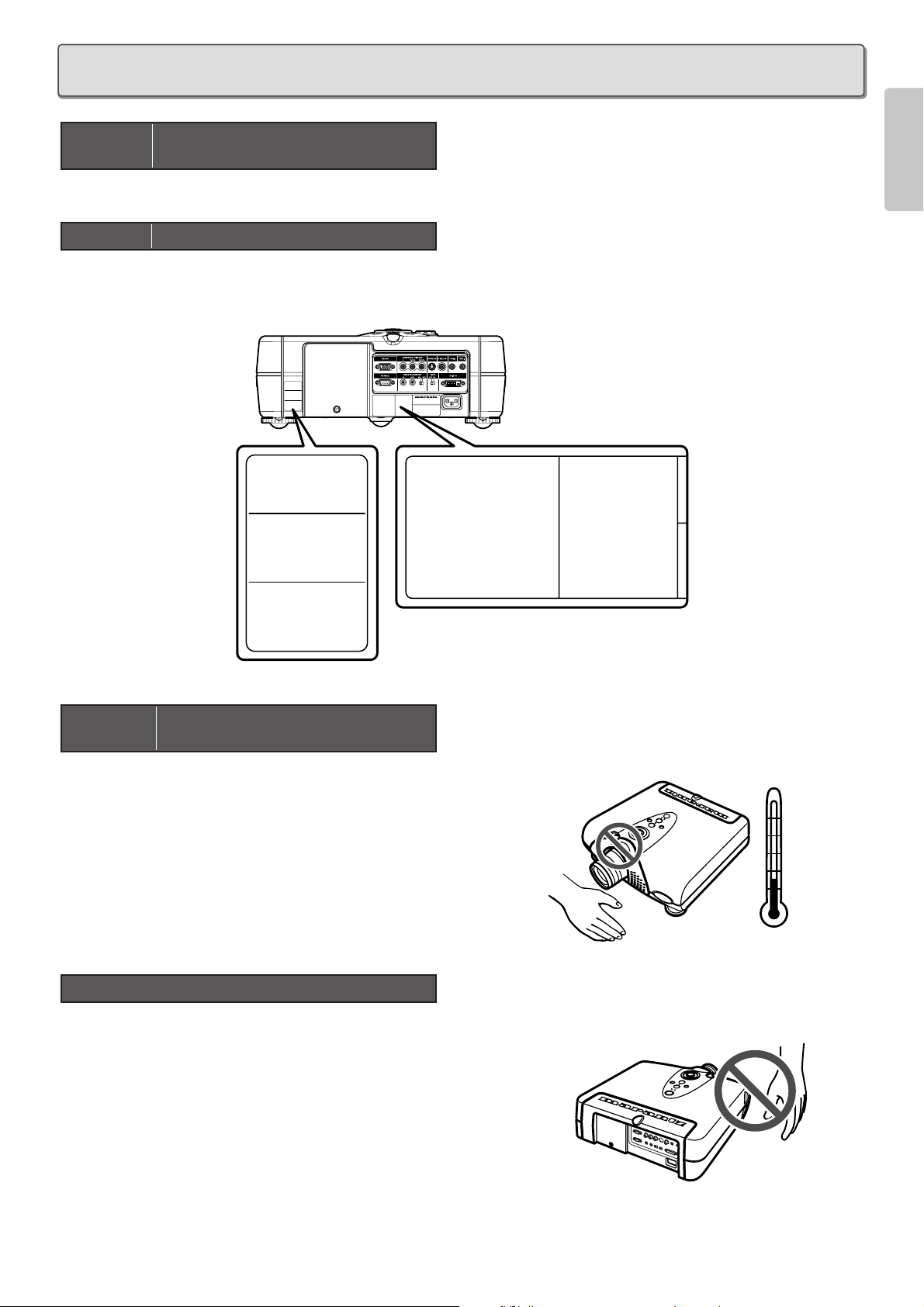
There is potential glass particle hazard if the lamp ruptures.
There is a potential hazard of glass particle if the lamp ruptures.
In case of lamp rupture,contact your nearest Marantz Authorized Dealer or Service Center for a replacement.
See “Replacing Lamp Unit”. (
☞
P.29)
For minimal servicing and to maintain high image quality, avoid humidity,
dust and cigarette smoke.
When the projector is subjected to these environments,the lens and
part of ventilation holes must be cleaned more often than usual. As long
as the projector is properly maintained in this manner, use in these
environments will not reduce the overall operation life. Please note that
all internal cleaning must be performed by an Marantz Authorized
Dealer, or Service Center.
• Do not expose the projector to extreme heat or cold.
Operating temperature:41 °F to 95 °F (+5 °C to 35 °C)
Storage temperature:–4 °F to 140 °F (–20 °C to +60 °C)
• The exhaust ventilative hole, the lamp cage cover and adjacent
areas may get extremely hot during projector operation. To
prevent injury,do not touch these areas until they have sufficiently
cooled down.
• Allow at least 1 foot (30 cm)of space between the exhaust
ventilative hole and the nearest wall or obstruction.
• If the cooling fan becomes obstructed, a protection device will
automatically turn off the projector lamp. This does not indicate a
malfunction. Remove the projector power cord from the wall outlet
and wait at least 10 minutes.
Then turn on the power by plugging the power cord back in. This
will return the projector to the normal operating condition.
Notes on Operation
Caution Concerning the Setup of the
Projector
MODEL NO. VP-12S2 / N1M
SERIAL NO.
CAUTION
HIGH PRESSURE LAMP MAY EXPLODED IF
IMPROPERLY HANDLED. REFER SERVICING
TO QUALIFIED SERVICE PERSONNEL.
ATTENTION
LA LAMPE SOUS HAUTE PRESSION PEUT
EXPLOSER SI ELLE, N'EST PAS MANIPULEE
CORRECTEMENT, CONFIER L'OPERATION
A UN PERSONNEL D'ENTRETIEN QUALIFIE.
VORSICHT
:
BEI FALSCHER HANDHABUNG
KANN DIE HOCHDRUCKLAMPE
EXPLODIEREN UBERLASSEN
SIE WARTUNGSARBEITEN
NUR FACHPERSONAL.
CAUTION HOT
UNPLUG THE POWER CORD AND
WAIT 60 MINUTES BEFORE
CHANGING THE LAMP.
ATTENTION CHAUD
DEBRANCER LE CORD ON
D'ALIMENTION ET ATENDER 60
MINUTES AVANT DE CHANGER
LAMPE.
WARNUNG HEISS
ZIEHEN SIE DEN NETZSTECKER
AB UND WARTEN SIE 60 MINUTEN,
BEVOR SIE DIE GLUHLAMPE
WECHSELN.
M
CAUTION
HIGH PRESSURE LAMP MAY EXPLODED IF
IMPROPERLY HANDLED. REFER SERVICING
TO QUALIFIED SERVICE PERSONNEL.
ATTENTION
LA LAMPE SOUS HAUTE PRESSION PEUT
EXPLOSER SI ELLE, N'EST PAS MANIPULEE
CORRECTEMENT, CONFIER L'OPERATION
A UN PERSONNEL D'ENTRETIEN QUALIFIE.
VORSICHT
:
BEI FALSCHER HANDHABUNG
KANN DIE HOCHDRUCKLAMPE
EXPLODIEREN UBERLASSEN
SIE WARTUNGSARBEITEN
NUR FACHPERSONAL.
CAUTION HOT
UNPLUG THE POWER CORD AND
WAIT 60 MINUTES BEFORE
CHANGING THE LAMP.
ATTENTION CHAUD
DEBRANCER LE CORD ON
D'ALIMENTION ET ATENDER 60
MINUTES AVANT DE CHANGER
LAMPE.
WARNUNG HEISS
ZIEHEN SIE DEN NETZSTECKER
AB UND WARTEN SIE 60 MINUTEN,
BEVOR SIE DIE GLUHLAMPE
WECHSELN.
Caution Concerning the Lamp Unit
Caution Concerning the Lamp
Replacement
95˚F
(+35˚C)
41˚F
(+5˚C)
IMPORTANT SAFEGUARDS
Page 6

2
ENGLISH
FEATURES
❖ Optics
• Texas Instruments DLP
TM
(Digital Light Processing)
Technology
• 1280 x 720 DMD
TM
Panel
• 16 : 9 Aspect Ratio
• Custom Optics Developed by Minolta
• 2600 : 1 Contrast Ratio
• 700 ANSI Lumens Brightness
• Brightness Uniformity : 90 %
• No Halo Effect
• Lens Up/Down Shift Construction
• Dust Free Optics Sealing
• No Light Leakage
(Double Seals Cabinet Structure)
• Extremely Quite (Noise Cancel Duct Construction,
Ceiling Color Wheel Motor)
• Long Life Lamp
(Average 2000 Hours)
• Double Shrink Seal Lamp Structure Minimizes
Burst Ratio
❖ Electronics & Software
• Full Digital Device
• 3 Faroudja Chips Inside
(Decoder, Doubler, and
Enhancer)
• 3-2 Pull Down
• 10-Bit Digital Gamma Processing
• Horizontal/Vertical Keystone Correction
• 480p, 720p,1080i adapted
• Four Picture Modes: Theater, Standard, Dynamic,
User
• Twelve Picture Memories
• 4 Aspect Modes
• Fine Menu
• Three Color Temperatures (5250K/6500K/9000K)
• Black Level Selection (0IRE/7.5IRE)
• Control through RS-232C
• Two trigger for powered Screen Control
• Ecology Lamp Mode
• Component Video Input
– DLP, Digital Micromirror Device and DMD are trademarks
of Texas Instruments.
– “DCDi” is a trademark of Faroudja, a division of Sage Inc.
– All trademarked product names mentioned in this manual
are the property of their respective companies.
Note: Pixel defects
DMDTM(Digital Micromirror DeviceTM) is one of the most
advanced technologies for consumer products. The DMD
TM
made by high precision technology, however some pixel
defects may be found on the projected image. We are
trying our best to control the quality in order to reduce the
number of defective pixels. It is almost impossible to have
zero pixel defects, even using the most advanced
technology. This is not a problem only for Marantz, but all
DLP
TM
projector manufactures. Therefore we have to note
that the warranty does not cover the DMD
TM
for pixel
defects. We appreciate your understandings.
Note: Lamp
SHP lamp is one of the most advanced technologies for
consumer products. The lamp made by high precision
technology, however some lamps might be failing before it
reaches its life. And projector’s brightness is getting darker
along with accumulated lamp usage hours. We are trying
our best to control the quality in order to reduce lamp
failures. It is almost impossible to have zero failure, even
using the most advanced technology. This is not a problem
only for Marantz, but all projector manufactures. Therefore
we have to note that the warranty does not cover the SHP
lamp for lamp failures: explosion, and non-lighting except
initial use. And also we have to note that the warranty does
not cover the SHP lamp for lamp failures: flickering, and
getting darker along with accumulated lamp usage hours.
We appreciate your understandings.
Page 7
3
ENGLISH
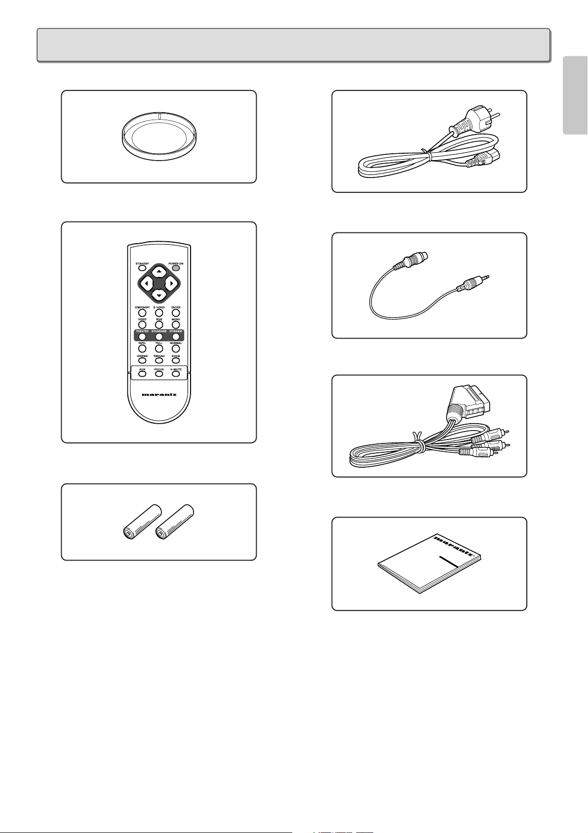
• Lens Cap x 1
• Remote Controller x 1
• AA Size Batteries x 2
• AC Power Code x 1
• Control Adapter Cable (Mini Jack to RCA) x 1
• Scart - RCA plug Cable x 1
• User Guide x 1
R
ACCESSORIES
Page 8
4
ENGLISH
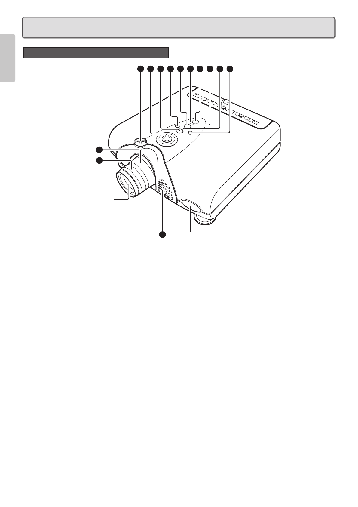
Front and Top View
q Focus ring (
☞
P.10)
Adjust the picture focus.
w Zoom ring (
☞
P.10)
Adjust the size of the projected image.
e Lens Shift knob (
☞
P.10)
Manually adjust the position of the image vertically.
r POWER key (
☞
P.15)
Press to turn the projector ON or STANDBY mode.
t MENU key (
☞
P.20)
Display the on-screen menu.
y ENTER key
Confirm "Reset All", "Reset Lamp Life", "New Lamp?".
u INPUT SELECT key (
☞
P.15)
When the key is pressed, the unit toggles between
COMPONENT, S-VIDEO, VIDEO, RGB and AUX inputs.
i FOCUS key (
☞
P.11)
Display a focus pattern.
o The 3 / 4 / 1 / 2 keys
Control the MENU cursor.
!0 POWER ON indicator
Lights up when the power is turned on. Flashes while the
projector goes into standby mode for about one minute.
!1 STANDBY indicator
Lights up when the power is turned off.
!2 WARNING/LAMP indicator
Flashes or lights up when something is wrong with the lamp
cover, lamp, fan, or temperature inside the projector.
!3 Ventilation holes
Notes:
• Do not place anything near the ventilation holes to avoid
overheat inside the unit.
• Do not place your hand or objects near the ventilation
holes; the air is coming out.
PROJECTOR LAYOUT AND FUNCTIONAL OVERVIEW
2
1
Projection
Lens
3
9 7 6 5 10 4 11 12 8
13
IR sensor
Page 9
5
ENGLISH
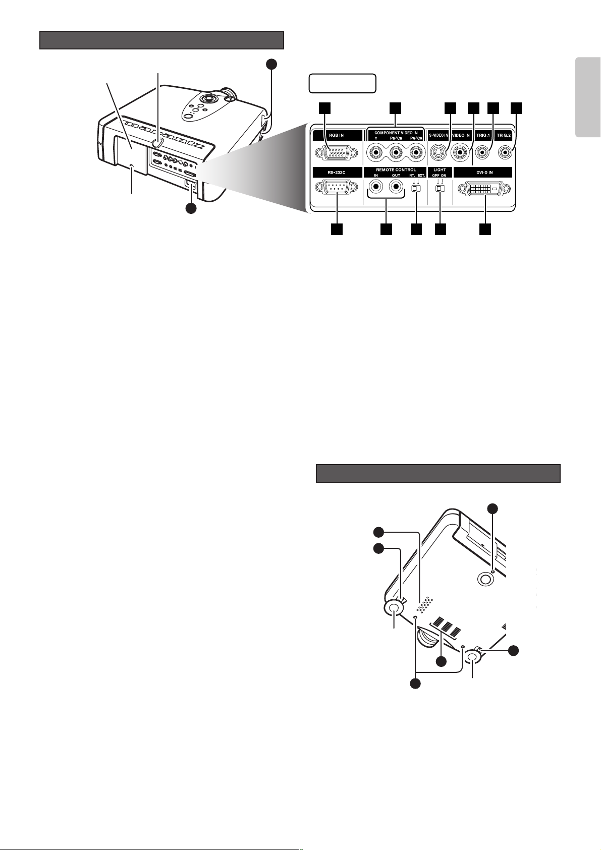
Rear and Terminals View
13
14
Lamp cover
securing screw
Lamp cover
IR sensor
1 2 3 4 5
7 8 9 10 11
Terminals
6
!4 AC IN (
☞
P. 8)
Connect the supplied AC power code.
❖ Terminals
z RGB IN
Connect the analog RGB output from an IBM VGA or compatible
equipment.
x COMPONENT VIDEO IN
Y, PB/CB, PR/CR connectors.
Connect the COMPONENT VIDEO output from video
equipment or an A/V processor/receiver with a component
video output.
c S-VIDEO IN
Connect the S-VIDEO output from a video equipment.
v VIDEO IN
Connect the composite video output from a video equipment.
b TRIG.1(TRIGGER 1)
When the unit is turned on, 12V is output. When the unit is
turned off, no voltage is output. This allows such as a powered
up/down screen,whenever the projector is turned on or off.
Note:
To connect with external devices, use an ordinal 35mm miniplug (mono) cable with attaching the supplied ferrite core.
n TRIG.2(TRIGGER 2)
Select ON or OFF at each aspect mode, such as Full, Normal,
Zoom, and Through to control screen aspect ratio with powered
up/down dual aspect ratio screen.
Notes:
• Do not use TRIG.1 and TRIG.2, as the power source.
• To connect with external devices, use an ordinal 35mm mini-
plug (mono) cable with attaching the supplied ferrite core.
m RS-232C
Connect the RS-232C of equipment for external control.
, REMOTE CONTROL IN/OUT
By connecting this projector to another Marantz audio component
using a supplied System Control cable, you can remotely operate
the components as a single system.
• When connecting to component with a remote sensor (such
as the SR9200,SR8200), be sure to connect the "REMOTE
CONTROL IN" jack of this projector to the "REMOTE
CONTROL OUT" jack of the component with the remote
sensor.
• When connecting to component which is not equipped with
a remote sensor, be sure to connect the component to the
"REMOTE CONTROL OUT" jack of this projector.
. REMOTE switch (EXT. / INT.)
When using this projector independently, set this switch to
"INT.". When using this projector in a system with a Marantz
DVD player or AV Receiver equipped with a remote sensor,
set the switch to "EXT.".
⁄0 LIGHT ON/OFF
Select ON : The terminal panel lights up.
⁄1 DVI-D IN
Connect the digital RGB signal (TMDS compliant, single link
only)
Note: To use the DVI-D terminal, please follow the cautions
on page 9.
!5 Adjustment lever (
☞
P.11)
Lift the projector and turn the adjustment lever right or left.
The adjustable feet will extend from the projector. Then,
release the lever, the adjustable feet is locked.
!6 Screw holes for ceiling mount kit
Bottom View
16
13
15
Adjustable
feet
13
16
Adjustable feet
15
Page 10
6
ENGLISH
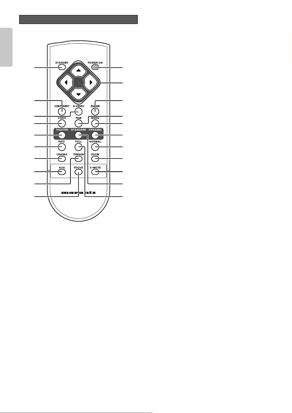
Remote Controller
a
d
g
l
¡2
¡5
¡7
™1
¡1
¡6
s
h
k
¡0
¡3
¡4
¡9
¡8
™0
j
f
PROJECTOR
a POWER ON key (
☞
P.10)
Turn the projector on.
s STANDBY key (
☞
P.18)
Turn the projector off.
d 3 / 4 / 1 / 2 keys
Control the MENU cursor.
f ENTER key
Confirm "Reset All", "Reset Lamp Life", "New Lamp?".
g MENU key (
☞
P.20)
Display the on-screen menu.
h COMPONENT key (
☞
P.15)
Select the COMPONENT VIDEO IN signal.
j S-VIDEO key (
☞
P.15)
Select the S-VIDEO IN signal.
k VIDEO key (
☞
P.15)
Select the VIDEO IN signal.
l RGB key (
☞
P.15)
Select the RGB IN signal.
¡0 THEATER key (
☞
P.27)
Select the Theater picture mode.
Theater mode is designed for high fidelity black appearance
and is good for movie pictures.
When the key is pressed, the mode toggles Theater 1,
Theater 2, Theater 3 and Theater Default.
¡1 STANDARD key (
☞
P.27)
Select the STANDARD picture mode.
Standard mode is good for normal pictures.
When the key is pressed, the mode toggles Standard 1,
Standard 2, Standard 3, and Standard Default.
¡2 DYNAMIC key (
☞
P.27)
Select the Dynamic picture mode.
Dynamic mode is good for visually dynamic pictures.
When the key is pressed, the mode toggles Dynamic 1,
Dynamic 2, Dynamic 3 and Dynamic Default.
¡3 INFO. key (
☞
P.27)
Turn the information menu on or off.
¡4 CINEMA key
Press to turn the CINEMA mode – auto 3-2 pull down mode –
on or off.
¡5 NORMAL key (
☞
P.15)
Select NORMAL mode from four aspect ratio modes.
¡6 FULL key (
☞
P.15)
Select FULL mode from four aspect ratio modes.
¡7 ZOOM key (
☞
P.15)
Select ZOOM mode from four aspect ratio modes.
¡8 THROUGH key (
☞
P.15)
Select THROUGH mode from four aspect ratio modes.
¡9 AUX key (
☞
P.15)
Select the DVI-D IN signal.
™0 FOCUS key (
☞
P.11)
Display a focus pattern.
™1 V-MUTE key
Turn the picture into black. Press again to resume.
Page 11
7
ENGLISH
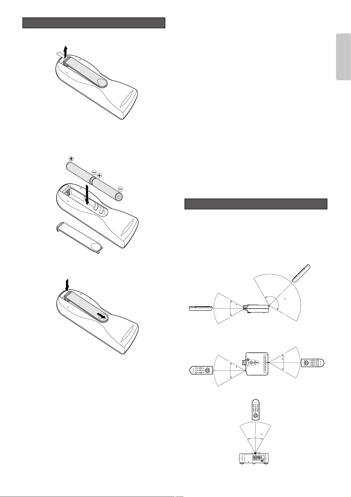
1. Open the Battery cover.
2. Insert two AA size batteries.
Make sure the polarities match the + and – marks inside
the battery compartment.
3. Close the battery cover.
Preparing the Remote Controller
CAUTION
– The available battery types are limited: manganese dry cell
and alkaline dry cell.
– Do not mix different battery types.
– Do not mix old and new batteries.
– Only batteries of the same type are to be used.
– Remove exhausted batteries from the Remote Controller.
– Do not attempt to recharge non-rechargeable batteries.
– Do not use rechargeable batteries.
– Batteries are to be inserted with the correct polarity.
– The supply terminals are not to be short-circuited.
– Never throw batteries in a fire or attempt to open up its outer
casing.
– If the user does not intend to use the Remote Controller for
a long time, remove the batteries.
– Keep away from heat.
– The effect range of the Remote Controller is approximately
6m.
– Do not be subjected to strong shock.
– Do not be subjected to moisture. If the unit gets moistured,
wipe it off immediately.
– The Remote Controller operation may not function if the
projector’s IR sensors are exposed to direct sun light or
strong artificial light, or if there is an obstacle between the
IR sensors and the Remote Controller.
Operate the remote controller within a distance of approximately
5m from the IR sensor (remote sensor) on the projector.
Remote control operation may not be possible if the remote
control unit’s transmitter is not pointing in the direction of the
remote sensor or if there is an obstruction between the
transmitter and the remote sensor.
Remote Controller Operational Range
Remote
Controller
Remote
Controller
Remote
Controller
Remote
Controller
Remote
Controller
5m
150
60
5m
5m
5m
60
VP-12S2
60
VP-12S2
5m
60
VP-12S2
Page 12
8
ENGLISH
❖ When making connections be sure to:
• Turn off all equipment before making any connections.
• Use the proper cables for each connection.
• Insert the plug properly. Any plugs that are not fully inserted often generate a noise.
❖ When pulling out a cable:
• Be sure to grab the plug, not the cable itself.
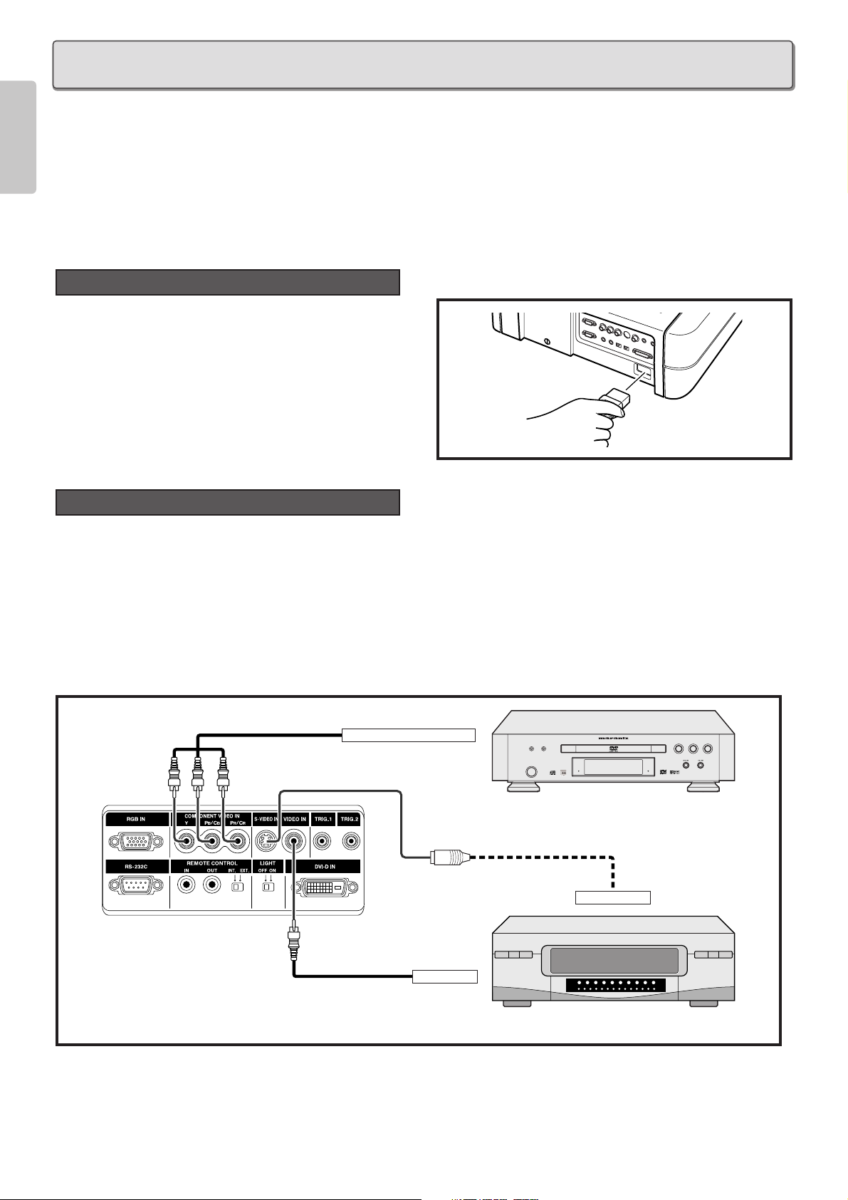
Connect the supplied AC power cord into the AC IN socket of
the projector.
The STANDBY indicator lights up and the projector goes into
the standby mode.
Note : Make sure the AC power cord is firmly connected into
the AC IN socket.
You can connect this projector to a VCR, DVD player and other video equipment.
Connecting a video source using S-VIDEO IN and VIDEO IN terminals.
1. Connect one of the S-video cable to the S-VIDEO IN terminal, or one end of the video cable to the VIDEO IN terminal on the projector.
2. Connect the other end of the S-video cable or the video cable to the S-video output terminal or video output terminal of the
video source.
Connecting with DVD player using COMPONENT VIDEO IN terminal
1. Connect each RCA connector of a component cable to the corresponding RCA terminals on the projector.
2. Connect the other end of the cable to the corresponding terminals on a DVD player.
DVD
VCR
FL OFF
STANDBY
S-VIDEO OUT
VIDEO OUT
COMPONENT VIDEO OUT
Component cable
(commercially available)
Video cable
(commercially available)
S-video cable (commercially available)
Connection with Video Equipments
Connection with AC Power Supply
CONNECTION
Page 13

9
ENGLISH
You can connect this projector to HD-Video /PC using RGB IN port, or Satellite /Cable Tuner /PC using DVI-D IN port.
1. Connect one end of the RGB cable to the RGB IN port, or one end of the DVI-D cable to the DVI-D IN port on the projector.
2. Connect the other end to the corresponding port on a HD-Video, Satellite, Cable Tuner or personal computer.
Note : When projecting a video image from a device connected to the DVI-D terminal, follow the procedure below.
1. Turn on power of this unit. (
☞
P.15)
2. Set the input video source to AUX (DVI-D input). (
☞
P.15)
3. Turn on power of the device connected to the DVI-D terminal of the unit (i.e. DVD player).
If the procedure above is not followed, projected image may corrupt.
For the details of the DVI-D terminal on the device connected with the unit, see the instruction manual of the device.
You can control total home theater system using PC or Marantz receiver equipment.
For installing below system, consult with Marantz authorized dealer.
Receiver equipment
External Controller
Screen
REMOTE CONTROL IN
REMOTE CONTROL OUT
RS-232C
35mm Mini Plug (Mono)
(commercially available)
Control Adapter cable
(supplied)
RS-232C cable
(straight type, commercially available)
(commercially available)
Advanced Connection
IBM VGA or
Compatible PC
HD-Video / Satellite
/ Cable Tuner
RGB OUT
or
DVI-D out
RGB (D-Sub monitor) cable
(commercially available)
Monitor output
RGB OUT
or
DVI-D out
DVI-D cable
(commercially available)
Connection with a HD-Video, Satellite, Cable Tuner or PC
Page 14

10
ENGLISH
1. Connect the supplied AC power cord. (
☞
P.8)
2. Press the POWER ON key on the remote controller or the POWER key on the projector.
The POWER ON indicator lights up.
Project an image on the screen roughly at first.
1. Turn the Zoom ring and adjust to the desired size within
the zoom range.
2. Turn the Focus ring until the image on the screen
becomes clear.
You can adjust the image position with the Lens Shift knob.
❖ Turn the Lens Shift knob to clockwise : The image goes up.
Adjusting the Image Position
Zooming and Focusing
Turning on the Power
Up
Clockwise
INITIAL SETTING
1.2.
Page 15

11
ENGLISH
❖ Turn the Lens Shift knob to counterclockwise : The image goes down.
Adjust the height of the image by raising the projector with the adjustment lever.
1. Operate the adjustment lever for releasing the adjustable feet. And lift the projector up carefully.
2. Remove your hands from the lever. Once the adjustable feet have locked in position, release the projector.
3. If the screen is at an angle, the adjusters can be used to adjust the angle of the image.
❖ Returning the Projector to its Initial Position
While holding the projector, press the foot releases and slowly lower the projector to its initial position.
You can strictly focus the image with focus pattern.
1. Press the FOCUS key to display the focus pattern.
Detail Focusing
Adjusting the Height
Down
Counterclockwise
Page 16

12
ENGLISH
2. Turn the Focus ring to make an adjustment.
Adjust the focus for the sharpest image possible to obtain, using focus pattern.
3. Press the FOCUS key again to clear off the pattern.
When the projecting image is a trapezoid, correct it in Keystone-V and/or Keystone-H in the Display Menu.
See “Display”. (
☞
P.24)
Keystone Correction
❖ Keystone-V
(Electronic vertical keystone correction)
❖ Keystone-H
(Electronic horizontal keystone correction)
Note : Electronic horizontal keystone correction works properly when the lens shift position is at Full Up.
See “Zooming and Focusing”.
(
☞
P.10)
Page 17

13
ENGLISH
❖ Installing on a tabletop
❖ Mounting on the ceiling
CAUTION
– For ceiling installation, consult with Marantz authorized dealer.
– Do not look into the lens when the projector is turned on. It could damage your eyesight.
Recommended Setting
INSTALLATION
Screen
Screen upper end
Screen
Range from light axis to upper end
Light axis (center)
Height from installing level to light axis
Installing level
Screen size (vertical)
Screen lower end
Projection distance
lens head
Lens shift range
Screen size (vertical)
Screen upper end
Range from light axis to upper end
Light axis (center)
Height from installing level to light axis
Screen lower end
Projection distance
lens head
Ceiling mount kit center
Lens shift range
Ceiling mount kit
(Optional)
Approx. 24 7/16
to 46 14/16 inch
(Approx. 62 to 119 cm)
[When the pole of EXT-81 is cut :
Approx. 12
10/16 to 24 7/16 inch
(Approx. 32 to 62 cm)]
10 7/16 inch
(26.5cm)
1 3/16 inch
(3 cm)
EXT-81
MOUNT12
Page 18

14
ENGLISH
❖ 16 : 9 Screen
In case of displaying the 16:9 picture on
the whole of the 16:9 screen.
❖ 4 : 3 Screen
In case of displaying the 16:9 picture on
the whole of the 4:3 screen.
Screen Size and Projection Distance
Screen size
(Diagonal)
Projection distance
Screen
Width
Height
: Image size = Screen size
VP-12S1
16:9 Screen Size (1.77:1 Aspect Ration) Projection Distance
Diagonal Width Height Minimum Maximum
inch mm mm m m
40
60
70
72
80
82
84
90
92
100
106
110
120
123
133
135
150
170
200
250
To calculate the installation measurement (unit : m)
886
1328
1550
1594
1771
1815
1860
1992
2037
2214
2347
2435
2657
2723
2944
2989
3321
3763
4428
5535
Minimum = (33.21 x Screen Size - 47.6)
Maximum= (38.46 x Screen Size - 47.6)
Note : Tolerance 5%
±
498
747
872
897
996
1021
1046
1121
1146
1245
1320
1370
1494
1532
1656
1681
1868
2117
2491
3113
1000
1000
1.28
1.95
2.28
2.34
2.61
2.68
2.74
2.94
3.01
3.27
3.47
3.61
3.94
4.04
4.37
4.44
4.93
5.60
6.59
8.25
1.49
2.26
2.64
2.72
3.03
3.11
3.18
3.41
3.49
3.80
4.03
4.18
4.57
4.68
5.07
5.14
5.72
6.49
7.64
9.57
Width
Height
: Image size
: Screen size
4:3 Screen Size (1.33:1 Aspect Ration) Projection Distance
Diagonal Width Height Minimum Maximum
inch mm mm m m
40
60
70
72
80
84
90
100
110
120
150
170
180
200
250
To calculate the installation measurement (unit : m)
813
1219
1422
1463
1626
1707
1829
2032
2235
2438
3048
3454
3658
4064
5080
Minimum = (30.49 x Screen Size - 47.6)
Maximum= (35.31 x Screen Size - 47.6)
Note : Tolerance 5%
±
610
914
1067
1097
1219
1280
1372
1524
1676
1829
2286
2591
2743
3048
3810
1.17
1.78
2.09
2.15
2.39
2.51
2.70
3.00
3.31
3.61
4.53
5.14
5.44
6.05
7.57
1000
1000
1.36
2.07
2.42
2.49
2.78
2.92
3.13
3.48
3.84
4.19
5.25
5.96
6.31
7.01
8.78
Page 19

15
ENGLISH
Press the POWER ON key on the remote controller or the POWER key on the projector.
The POWER ON indicator lights up.
Switch to the equipment connected to the projector.
Press the INPUT SELECT key on the projector or the COMPONENT key, S-VIDEO key, VIDEO key, RGB key or AUX key on the
remote controller.
You can select 4 kinds of ASPECT mode using remote controller.
Press the FULL key, NORMAL key, ZOOM key, or THROUGH key on the remote controller.
You can select the mode using on-screen menu, too.
Selecting the Aspect Mode
Selecting the Input Signal Source
Turning on the Power
BASIC OPERATIONS
Select a key
Select a key
Page 20

16
ENGLISH
• Press the ZOOM key, the NORMAL key or the FULL key on the remote controller for the 4:3 aspect ratio video source.
• Press the FULL key on the remote controller for 16:9 aspect ratio video source, such as 1080i, 1035i, and 720p video systems.
• Press the FULL key on the remote controller for the squeezed video source.
See “Setting”. (☞P.23)
The Screen Images in a 16:9 screen
❖ Original Source Image
❖ Full mode
The 16:9 squeezed image is displayed with the correct
aspect.
❖ Normal mode
❖ Zoom mode
The 4:3 image is enlarged horizontally.
The picture in normal ratio 4:3 is displayed.
The picture in normal ratio 4:3 is enlarged vertically and
horizontally (with same ratio) to the screen size
4 : 3 video source16 : 9 video source
❖ Through mode
It shows an image when the video source has the same resolution to RGB/video signal with 720 or less vertical pixel number.
Page 21

17
ENGLISH
• Press the ZOOM key, the NORMAL key or the FULL key on the remote controller for the 4:3 aspect ratio video source.
• Press the FULL key on the remote controller for 16:9 aspect ratio video source, such as 1080i, 1035i, and 720p video systems.
• Press the FULL key on the remote controller for the squeezed video source.
See “Setting”. (☞P.23)
The Screen Images in a 4:3 screen
❖ Original Source Image
❖ Full mode
The 16:9 squeezed image is displayed with the correct
aspect.
❖ Normal mode
❖ Zoom mode
The 4:3 image is enlarged horizontally.
The picture in normal ratio 4:3 is displayed.
The picture in normal ratio 4:3 is enlarged vertically and
horizontally (with same ratio) to the screen size
4 : 3 video source16 : 9 video source
❖ Through mode
It shows an image when the video source has the same resolution to RGB/video signal with 720 or less vertical pixel number.
Page 22

18
ENGLISH
1. Press the STANDBY key on the remote controller or the POWER key on the projector.
2. The fan continues to run for a while to reduce internal heat. The POWER ON indicator flashes in blue and no key will be
active. After about one minute of cooling has been done, the unit turns off and the STANDBY indicator lights up.
Notice : Do not pull out the AC power cord until the projector turns in standby mode.
Notice :
- Do not pull out the power cord suddenly in the state of “POWER ON." It can cause a breakdown.
- When a WARNING indicator lit up or blinks in red, pull out the AC power cord after checking that the fan has stopped.
- The projector will not be turned on if the POWER ON key on the remote controller or the POWER key on the projector is
pressed immediately after turning off. Press the POWER ON key on the remote controller or POWER key on the projector
after the projector turns into standby mode.
To Turn off the Power
Page 23

19
ENGLISH
Menu Structure
OPERATIONS
Main Menu
Picture Adjust
Setting
Display
Item
Contrast
Brightness 0 63
Color 0 100
Sharpness 0 31
Tint R50 G50
Noise Reduction 0 63
Color Temp. (Temperature) L M H
Fine Menu
Aspect
Cinema Auto / Off
Black Setup 0IRE / 7.5IRE
Component
Video System
RGB System
DVI System RGB
Keystone V (Vertical)
Keystone H (Horizontal)
Auto Adjust
Picture Shift V (Vertical) Down Up
Size V (Vertical) Small Large
Picture Shift H (Horizontal) Left Right
Size H (Horizontal)
Phase
Backward Forward
0 100
Full
Normal
Through
Zoom
Auto
NTSC
PAL
480p
540p
576p
720p
1035i
1080i
Auto
NTSC
PAL
SECAM
Auto
NTSC
PAL
480p
540p
576p
720p
1035i
1080i
Y PB PR
Y CB CR
Yes / No
Small Large
Fine Menu
Luminance
Chrominance
Sub Control
Miscellaneous
Main Menu
Config (Configuration)
Trigger 2 Full On / Off
Memory Theater 1 / 2 / 3 / Default
Lamp mode
High Bright On / Off
OSD Position
Language
Ceiling On / Off
Rear On / Off
Reset Lamp Life Yes / No
Reset All Yes / No
Normal On / Off
Through On / Off
Zoom On / Off
Standard
Dynamic
User
H Detail Gain
H Detail Threshold
H Edge Gain
H Edge Threshold
V Detail Gain
V Detail Threshold
V Edge Gain
V Edge Threshold
H Edge Gain
H Edge Threshold
V Edge Gain
Enhancement
Delay
Contrast Red
Contrast Green
Contrast Blue
Brightness Red
Brightness Green
Brightness Blue
DCDi
FRC
CCS
VCR Mode
Item
031
031
031
031
031
031
031
063
031
031
031
031
0+3–3
0 255
0 255
0 255
0 255
0 255
0 255
On / Off
Auto / On
On / Off
On / Off
High / Low
16 : 9
4 : 3
English
German
French
Spanish
Italian
Portuguese
1 / 2 / 3 / Default
1 / 2 / 3 / Default
1 / 2 / 3 / Default
Page 24

Refer to the on-screen menu for making various adjustments and settings. (☞P.19)
1. Press the MENU key. The MENU appears.
2. Use 3 / 4 / 1 / 2 keys to select a menu item.
3. Make adjustments in Picture Adjust, Setting, Display, Configuration, Trigger2, or Memory.
4. Press the MENU key to exit. The MENU disappears.
Adjust the picture to suit own preference by using the Picture Adjust feature.
❖ For a video signal input, the following adjustments can be made:
NOTE:
- You cannot adjust Tint in Component signal (YC
BCR
/YPBPR)
or PAL format signal.
- If User Memory is set to default, Picture Adjust cannot be
selected. To select Picture Adjust, set User Memory to
either 1 to 3.
See “Memory”. (
☞
P.27)
❖ Setting the Picture Adjust Menu
1. Use 1 / 2 key to adjust.
2. Use 3 key to go back to the menu item.
❖ Contrast
❖ Color Temp. (Temperature)
H : Make white color bluer.
M : Make white color less blue. This setting is approximately 6500 Kelvin.
L : Make white color redder.
Color Temp. Low Middle High
Contrast 50
Picture Adjust
Using On-Screen Menu
20
ENGLISH
Item
Contrast
Brightness
Color
Sharpness
Tint
Noise Reduction
Color Temp. (Color Temperature)
Adjustments
0 100
Weak Strong
063
Dark Bright
0 100
Light Deep
031
Soft Sharp
R50 G50
Purple Green
063
Weak Strong
LMH
Red Middle Blue
1, 42.
Picture Adjust
Setting
Display
Config
Trigger 2
Memory
Contrast
Brightness
Color
Sharpness
Tint
Noise Reduction
Color Temp.
Fine Menu
50
44
64
6
0
0
Middle
2.
1, 4
2.
2.
1.
1.
Page 25

21
ENGLISH
By adjusting this Fine Menu, you can make fine picture adjustment.
Note : There are some parameters can not adjust according to input signal.
❖ Luminance
H Detail Gain (Horizontal Detail Processing Gain)
: This menu allows the users to set the horizontal detail processing gain.
H Detail Threshold (Horizontal Detail processing Threshold)
: This menu allows the users to set the lower threshold for horizontal detail processing.
H Edge Gain (Horizontal Large Edge Enhancement Gain)
: This menu allows the users to set the horizontal large edge enhancement.
H Edge Threshold (Horizontal Large Edge Enhancement Threshold)
: This menu allows the users to set the lower threshold for horizontal large edge enhancement.
V Detail Gain (Vertical Detail Processing Gain)
: This menu allows the users to set the vertical detail processing gain.
V Detail Threshold (Vertical Detail Processing Threshold)
: This menu allows the users to set the lower threshold for vertical detail processing.
V Edge Gain (Vertical Large Edge Enhancement Gain)
: This menu allows the users to set the vertical large edge enhancement.
V Edge Threshold (Vertical Large Edge Enhancement Threshold)
: This menu allows the users to set the lower threshold for vertical large edge enhancement.
Note : If it is hard to see the effect, make the sharpness higher and adjust it.
❖ Chrominance
H Edge Gain (Horizontal Large Edge Enhancement Gain)
: This menu allows the users to set the horizontal large edge enhancement.
H Edge Threshold (Horizontal Large Edge Enhancement Threshold)
: This menu allows the user to set the lower threshold for horizontal large edge enhancement.
V Edge Gain (Vertical Large Edge Enhancement Gain)
: This menu allows the users to set the vertical large edge enhancement.
Enhancement (Enhancer Gain)
: This menu allows the users to set the over all enhancement level.
Delay
: This menu allows the users to set the delay.
Luminance
Chrominance
Sub Control
Miscellaneous
H Edge Gain
H Edge Threshold
V Edge Gain
Enhancement
Delay
3
6
8
6
0
Luminance
Chrominance
Sub Control
Miscellaneous
H Detail Gain
H Detail Threshold
H Edge Gain
H Edge Threshold
V Detail Gain
5
11
5
9
5
V Detail Threshold
V Edge Gain
V Edge Thresh.
6
4
5
Fine Menu
Item
H Detail Gain
H Detail Threshold
H Edge Gain
H Edge Threshold
V Detail Gain
V Detail Threshold
V Edge Gain
V Edge Threshold
Adjustments
031
031
031
031
031
031
031
063
Item
H Edge Gain
H Edge Threshold
V Edge Gain
Enhancement
Delay
Adjustments
031
031
031
031
– 30+ 3
Page 26

22
ENGLISH
❖ Sub Control
Contrast Red
: This menu allows the users to set the contrast for red.
Contrast Green
: This menu allows the users to set the contrast for green.
Contrast Blue
: This menu allows the users to set the contrast for blue.
Brightness Red
: This menu allows the users to set the brightness for red.
Brightness Green
: This menu allows the users to set the brightness for green.
Brightness Blue
: This menu allows the users to set the brightness for blue.
❖ Miscellaneous
DCDi
: This menu allows the users to control DCDi.
FRC (Frame Rate Conversion)
Auto : Frame Rate Conversion function is basically off. However FRC turns on automatically depending on vertical
frequency of input signal.
ON : Frame Rate Conversion function is “ON”. (60Hz fixed)
CCS (Cross Color Suppressor Function)
ON : Cross color suppressor enabled.
OFF : Cross color suppressor disabled. For like progressive scan DVD players, where most of the source material does
not contain any cross color, use this mode.
VCR Mode
ON : A projector is forced into the intra-field only deinterlacing mode.
OFF : A projector is used with external field memories and operates in the full set of deinterlacing modes, i.e., motion
adaptive video deinterlacing and full frame film source deinterlacing using 3:2 pulldown detection (2:2 pulldown
for 625/50 sources).
Luminance
Chrominance
Sub Control
Miscellaneous
DCDi
FRC
CCS
VCR Mode
On
Auto
Off
Off
Luminance
Chrominance
Sub Control
Miscellaneous
Contrast Red
Contrast Green
Contrast Blue
Brightness Red
Brightness Green
Brightness Blue
128
128
128
128
128
128
Item
Contrast Red
Contrast Green
Contrast Blue
Brightness Red
Brightness Green
Brightness Blue
Adjustments
0 255
0 255
0 255
0 255
0 255
0 255
Item
DCDi
FRC
CCS
VCR Mode
Adjustments
On Off
Auto On
On Off
On Off
Page 27

23
ENGLISH
The following settings can be made:
Aspect Full, Normal, Through, Zoom
Cinema Auto, Off
Cinema mode : The 3-2 pull down for NTSC
and the 2-2 pull down for PAL
Black Setup 0IRE, 7.5IRE
Black level adjustment, for adjusting black
level by a video source.
NOTE : Black Setup is not available for
IEEE1394 signal : AUX in signal.
Component Auto, NTSC, PAL, 480p, 540p, 576p,
720p, 1035i, 1080i
Video System Auto, NTSC, PAL, SECAM
RGB System Auto, NTSC, PAL, 480p, 540p, 576p,
720p, 1035i, 1080i
DVI System RGB, YPBPR, YCBCR
Color space conversion select for DVI input.
RGB: Color Space Conversion is skipped.
YP
BPR: This mode is suitable for HD TV
signal such a 720p, 1080i.
YC
BCR: This mode is suitable for SD TV
signal such a 480i, 480p.
❖ Setting the Setting Menu
1. Use 3 / 4 key to adjust.
2. Use 1 key to go back to the menu item.
Setting
NTSC(NTSC-3.58)
: Conventional analog broadcasting used
mainly in USA, Canada, Taiwan, Korea, and
Japan.
PAL(PAL-4.43)
: Conventional analog broadcasting used
mainly in United Kingdom and Germany.
SECAM : Conventional analog broadcasting used
mainly in France and Russia.
480p : Standard digital broadcasting
540p : Special digital broadcasting
(for example: RCA DTC100)
576p : Standard digital broadcasting
720p, 1080i : High Definition digital broadcasting
1035i : Japanese "Hi-Vision" broadcasting
Picture Adjust
Setting
Display
Config
Trigger 2
Memory
Aspect
Cinema
Black Setup
Component
Video System
RGB System
DVI System
Full
Auto
0 IRE
Auto
Auto
Auto
RGB
1.
2.
1.
2.
Page 28

24
ENGLISH
The following adjustments can be made:
– Keystone H, V
Adjust trapezoid image to rectangle image.
– Auto Adjust
Yes : For RGB IN signal, Picture Shift V and H, Size V and H, and Phase are adjusted automatically.
No : If something wrong with AUTO Adjust, select No, and adjust Size V, Size H, Picture Shift H, Picture Shift V, and/or Phase
manually.
Use
1 / 2 key to select “Yes”, and press the ENTER key.
– Picture Shift V, H
Adjust the position of the picture. H adjusts the horizontal position of the picture. V adjusts the vertical position of the picture.
– Size V, H
Adjust the vertical and horizontal size of the picture.
– Phase
Adjust the phase of the DMD
TM
dots and the computer signal input from the RGB IN. Adjust the picture to where it looks
clearest.
NOTE:
- If User Memory is set to default, Picture Shift V, H cannot be selected. To select Picture Shift V, H, set User Memory to either 1 to 3.
See “Memory”. (
☞
P.27)
❖ Setting the Display Menu
1. Use 1 / 2 key to adjust.
2. Use 3 key to go back to the menu item.
Display
Picture Adjust
Setting
Display
Config
Trigger 2
Memory
Keystone V
Keystone H
Auto Adjust
Picture Shift V
Size V
Picture Shift V
Size H
Phase
0
0
50
50
50
50
12
Keystone-V (Electronic vertical
keystone correction)
Keystone-H (Electronic horizontal
keystone correction)
Auto Adjust
Picture Shift V
Size V
Picture Shift H
Size H
Phase
Item Adjustments
Down
Small
Small
Backward
Left
Yes / No
Up
Large
Right
Large
Forward
2.
1.
2.
1.
Page 29

25
ENGLISH
The following adjustments can be made:
– OSD Position (16:9 / 4:3)
Select OSD position from 16:9 or 4:3.
– Reset Lamp Life
Lamp Life must be reset immediately if the lamp is replaced. Select “Reset Lamp Life” from Config menu. The menu shown
below is displayed.
Again, select “Yes”, and press the ENTER key. Then the lamp life is initialized.
– Reset All
All settings are reset to the factory default settings except the lamp life.
When the user selects “Yes”, the following message appears:
Again, select “Yes”, and press the ENTER key.
Yes No
Reset All?
Yes No
Reset Lamp Life?
4 : 3 OSD position16 : 9 OSD position
Picture Adjust
Setting
Display
Config
Trigger 2
Memory
Contrast
Brightness
Color
Sharpness
Tint
Noise Reduction
Color Temp.
Fine Menu
50
44
64
6
0
0
Middle
Picture Adjust
Setting
Display
Config
Trigger 2
Memory
Contrast
Brightness
Color
Sharpness
Tint
Noise Reduction
Color Temp.
Fine Menu
50
44
64
6
0
0
Middle
Picture Adjust
Setting
Display
Config
Trigger 2
Memory
Lamp Mode
High Bright
OSD Position
Language
Ceiling
Rear
Reset Lamp Life
Reset All
High
Off
16:9
English
Off
Off
Configuration
Lamp mode High, Low
High Bright On, Off
High Bright On : Display brightest image.
OSD Position 16:9, 4:3
Language English, German, French, Spanish,
Portuguese, Italian
Ceiling On, Off
On: The picture is reversed horizontally
and vertically.
Rear On, Off
On: The picture is reversed horizontally.
Reset Lamp Life Yes, No
Reset All Yes, No
Page 30

26
ENGLISH
❖ Setting the Config Menu
1. Use 3 / 4 key to adjust.
2. Use 1 key to go back to the menu item.
Select either 12V output or 0V output by choosing On or Off for each aspect mode. Full, Normal, Zoom, and Through.
On: Output DC 12V.
Off: No output.
This allows you to control such as a powered dual aspect screen with the outputs for the aspect modes.
❖ Setting the Trigger 2 Menu
1. Use 3 / 4 key to adjust.
2. Use 1 key to go back to the menu item.
Trigger 2
1.
2.
1.
2.
Picture Adjust
Setting
Display
Config
Trigger 2
Memory
Full
Normal
Through
Zoom
On
On
On
On
1.
2.
1.
2.
Page 31

27
ENGLISH
This unit has 4 picture modes, Theater, Standard, Dynamic, User, for your choice. You can choose one with the direction buttons
on the unit or on the remote.
• Theater : This mode is designed for high fidelity black appearance and is good for movie pictures.
• Standard : This mode is good for normal pictures.
• Dynamic : This mode is good for visually dynamic pictures.
• User : This mode allows you to adjust your favorite gamma curve.
Note : It is possible to download the software for making the gamma curve from our web.
Also, each mode has 3 User Memories and Default. If Default is set, you cannot select "Picture Adjust" and "Display" in the menu.
– Store memory
From the menu above, select "Memory" and choose one memory mode from 1-3 for either "Theater", "Standard", "Dynamic" or
"User" with the remote controller. Picture Adjust menu will be displayed. Adjust the picture and the adjustment settings will be
stored in the memory automatically.
❖ Setting the Memory Menu
1. Use 3 / 4 key to adjust.
2. Use 1 key to go back to the menu item.
❖ Lamp Life
Display the remaining lamp life by pressing the INFO. key on the remote controller.
Notes:
• The maximum life limit of the lamp is 2,000 hours. Although we care very much about quality, the lamp can rarely breaks down if
running time exceeds 1,000 hours. Therefore we recommend to replace the lamp if Lamp Life gets under 1,000 hours. The lamp
cannot be used exceeding the maximum life limit.
• This product is checked under strict quality control when it is shipped out form factory.
“Total Hours” in the menu includes the time for this check. So “Total Hours” may not be 0 hours when it is used first time.
Lamp Life and Replace Lamp
Memory
Picture Adjust
Setting
Display
Config
Trigger 2
Memory
Mode Standard
2
1.
2.
1.
2.
Video Input Component-1080i
Memory Standard 2
Cinema Mode Auto
Noise Reduction 0
Aspect Full
Trigger 2 On
Lamp Life 921 Hours
Total Hours 3653 Hours
Page 32

28
ENGLISH
– When the lamp life becomes less than 100 hours and the unit is still on, the remaining lamp life is displayed on the screen
automatically.
– When the lamp life becomes less than 5 hours, the remaining lamp life is displayed on the screen .
To clear the warning, press the MENU key.
– When the lamp life has expired (Lamp Life 0 HOURS), the unit will be immediately turned off, and the WARNING indicator will
light up in red.
❖ Initialize the Lamp Life
If the lamp is replaced to new one, follow this procedure to reset (initialize) the lamp life.
Refer to "Replacing Lamp Unit". (
☞
P.29)
1. Connect the AC power cord after replacing lamp unit. (
☞
P.8)
2. Press the POWER ON key on the remote controller or the POWER key on the projector.
The following message appears for 120 seconds.
3. Select “Yes”, using the 1 / 2 keys.
4. Press the ENTER key . The lamp life indicator is now initialized.
Warning
Lamp Life 100 Hours
Warning
Lamp Life 5 Hours
Warning
Lamp Life 0 Hours
New Lamp ?
Yes No
3.
4.
2.
2.
3.
4.
Page 33

29
ENGLISH
1. Press the STANDBY key on the remote controller or the
POWER key on the projector to turn the projector off.
2. After the cooling fan stops, Unplug the AC power cord.
3. Wait at the least one hour for the lamp and lamp unit to
cool down.
4. Read the caution and warning labels on the unit.
5. Remove the lamp cover screw.
6. Remove the lamp cover in the direction of the arrow.
7. Remove the two screws of the lamp unit. At this time, do
not remove the other screws.
Lamp cover
Lamp cover
MAINTENANCE
CAUTION:
• Do not touch the lamp and the lamp unit carelessly. It is extremely hot. Wait at least one hour for the lamp to cool down before
handling.
• Do not loosen any screws except for those mentioned below.
• The lamp may break if handled improperly.
• Do not use other than a Marantz replacement lamp unit.
❖ How to replace the Lamp Unit
PREPARATION:
When replacing the lamp, turn off the power for the projector. After the cooling fan stops, disconnect the power cord and wait
for one hour until the lamp is cooled down completely, then replace the lamp.
Replacing Lamp Unit
MODEL NO. VP-12S2 / N1M
SERIAL NO.
CAUTION
HIGH PRESSURE LAMP MAY EXPLODED IF
IMPROPERLY HANDLED. REFER SERVICING
TO QUALIFIED SERVICE PERSONNEL.
ATTENTION
LA LAMPE SOUS HAUTE PRESSION PEUT
EXPLOSER SI ELLE, N'EST PAS MANIPULEE
CORRECTEMENT, CONFIER L'OPERATION
A UN PERSONNEL D'ENTRETIEN QUALIFIE.
VORSICHT
:
BEI FALSCHER HANDHABUNG
KANN DIE HOCHDRUCKLAMPE
EXPLODIEREN UBERLASSEN
SIE WARTUNGSARBEITEN
NUR FACHPERSONAL.
CAUTION HOT
UNPLUG THE POWER CORD AND
WAIT 60 MINUTES BEFORE
CHANGING THE LAMP.
ATTENTION CHAUD
DEBRANCER LE CORD ON
D'ALIMENTION ET ATENDER 60
MINUTES AVANT DE CHANGER
LAMPE.
WARNUNG HEISS
ZIEHEN SIE DEN NETZSTECKER
AB UND WARTEN SIE 60 MINUTEN,
BEVOR SIE DIE GLUHLAMPE
WECHSELN.
M
CAUTION
HIGH PRESSURE LAMP MAY EXPLODED IF
IMPROPERLY HANDLED. REFER SERVICING
TO QUALIFIED SERVICE PERSONNEL.
ATTENTION
LA LAMPE SOUS HAUTE PRESSION PEUT
EXPLOSER SI ELLE, N'EST PAS MANIPULEE
CORRECTEMENT, CONFIER L'OPERATION
A UN PERSONNEL D'ENTRETIEN QUALIFIE.
VORSICHT
:
BEI FALSCHER HANDHABUNG
KANN DIE HOCHDRUCKLAMPE
EXPLODIEREN UBERLASSEN
SIE WARTUNGSARBEITEN
NUR FACHPERSONAL.
CAUTION HOT
UNPLUG THE POWER CORD AND
WAIT 60 MINUTES BEFORE
CHANGING THE LAMP.
ATTENTION CHAUD
DEBRANCER LE CORD ON
D'ALIMENTION ET ATENDER 60
MINUTES AVANT DE CHANGER
LAMPE.
WARNUNG HEISS
ZIEHEN SIE DEN NETZSTECKER
AB UND WARTEN SIE 60 MINUTEN,
BEVOR SIE DIE GLUHLAMPE
WECHSELN.
Page 34

30
ENGLISH
8. Holding the handle and pull the lamp unit out toward your
side.
9. Install a new lamp unit in position securely.
10. Tighten the two screws of the lamp unit. Push and fold
the handle.
11. Install the lamp cover back in its original position and
fasten with the fastening screw.
12. Plug in the video projector and turn on the power and
project the image. Reset the Lamp Life. (
☞
P.25)
If the lens becomes dirty or smudged, clean it with a soft
dry cloth only. Use optical lens cleaners that are approved
for eyeglasses or cameras. Do not use a dampen cloth,
detergent solution, or thinner. It may damage the lens and
remain as stains.
When replacement parts are required, be sure to inform a
Marantz authorized service center. Use only replacement
parts specified by Marantz. Unauthorized substitutions
may result in fire, electric shock, or other hazards. And,
the warranty may not be guaranteed.
• Lamp Unit : LU-12VPS1
• Ceiling Mount kit : MOUNT 12
This kit is specially designed to mount the unit on ceiling.
• Extension Pole : EXT-81
This tool is to adjust height with the Ceiling Mount Kit
MOUNT 12.
CAUTION:
For ceiling installation, consult with the Marantz Authorized
dealer.
Optional Accessories
Replacement Parts
Cleaning the Lens
Lamp unit
(a)
(b)
Page 35

31
ENGLISH
No power
Image is not displayed.
Poor color.
Picture is too dark.
Picture is not clear.
Picture rolls.
The Remote Controller
does not work.
AC power cord is not connected correctly.
Lamp cover is not closed correctly.
A signal cable is not connected correctly.
Selected input is incorrect.
The picture mute is active.
Picture is not adjusted properly.
Lamp life is running out.
Contrast or brightness is not adjusted properly.
Picture is out of focus.
Dew is on the lens.
A signal cable is not properly connected.
Batteries are exhausted.
The distance to the unit is too far.
IR sensor on unit is obstructed.
The “EXTERNAL” position on the connector
panel is selected.
Connect the AC power cord properly.
Close the cover properly.
Connect a signal cable properly.
Select the correct input source .
Press the MUTE key to release the mute.
Adjust the picture in the MENU mode.
Replace the lamp.
Adjust contrast or brightness properly.
Adjust the focus.
Run the projector for about two hours.
Connect a signal cable properly.
Replace batteries.
Make the distance between the unit and the
remote control closer.
Remove any obstacles.
Select the “INTERNAL” position.
Note:
• If the lamp still does not function after the replacement and initialization of the lamp life, contact a Marantz authorized dealer, or
service center.
Possible CauseSymptom Remedy
Try the following troubleshooting before calling for service.
1. Are the connections made properly ?
2. Are you operating the unit properly, following the
instructions ?
If the unit does not operate properly, check the items shown
in the following table.
If any trouble cannot be solved by the instructions below,
malfunction of the internal circuitry is suspected; immediately
unplug the AC power cord and contact Marantz dealer or
service center.
WARNING/LAMP indicator, POWER ON indicator, and STANDBY indicator diagnose error mode of the projector as follows.
The lamp cover is not
closed properly.
The lamp has failed, or
the lamp is completely
worn out.
Temperature around
the lamp unit becomes
unusually high.
Temperature around
the power supply
becomes unusually
high.
The fan inside the
projector has stopped.
Lamp cover
Lamp
Lamp
temperature
Power supply
Fan
ON
ON
Flashing
Flashing
Flashing
OFF
OFF
ON
ON
OFF
Flashing
OFF
Flashing
OFF
ON
Close the cover correctly.
Replace the lamp and
reset lamp life.
Check that nothing is
blocking the ventilation
holes, and leave off the
unit for about an hour.
Indicators
Error mode
WARNING
/LAMP
POWER ON STANDBY
Possible Cause Recommendation
ERROR MODE
TROUBLESHOOTING
Page 36

32
ENGLISH
❖ Optical characteristics
Panel 0.8 inch 16:9
1280 x 720 pixels
Digital Micromirror Device
TM
Lamp Super High Pressure 150W
Lens f: 26.5 to 30.7 / F: 3.0
Projection size 40 to 250 inches
Light output 700 ANSI LUMEN typical
❖ Input/Output
VIDEO IN RCA x 1
NTSC-3.58/PAL-4.43/SECAM
Composite video 1.0Vp-p/75 Ohm
S-VIDEO IN S-Connector x 1
NTSC-3.58/PAL-4.43/SECAM
S-Video
COMPONENT IN RCA x 3
Y, C
B/PB, CR/PR
RGB/HD IN D-sub M 15 pin x 1
Analog RGB
HD:1080i, 720p, 480p
DVI-D IN DVI-D 24pin x 1
T.M.D.S compliant (single link only)
☞
P.33
REMOTE CONTROLLER IN
Mini jack type x 1
REMOTE CONTROLLER OUT
Mini jack type x 1
AC IN 3 Prong Grounding Type
TRIG.1 OUT, TRIG.2 OUT
Mini Jack x 2
Output: DC12V or 0V
RS232C RS232C receptacle plug x 1
❖ General
Power requirement AC 100-120V / 220-240V, 50/60 Hz
Power consumption < 250 W
Standby consumption < 3.3 W
Chassis isolation Class-1
Safety UL6500
CSA E60065
EN60950
EMC FCC Part-15 Class-B
EN55022 Class-B
Dimensions 404.5(W) x 471(D) x 158(H) mm
Net weight 13 kg
Operating Temperature 5 to 35 °C
Operating humidity 30 to 85%
Storage Temperature – 20 to 60 °C
Storage humidity 30 to 85%
❖ Accessories
• Lens cap x 1
• Remote controller x 1
• Batteries x 2
• AC power code x 1
• Control Adapter cable (Mini jack to RCA) x 1
• Scart - RCA plug Cable x 1
• User Guide x 1
Specifications may be subjected to change without any prior notice.
SPECIFICATIONS
NO SIGNAL
REPLACE LAMP!
OUT OF RANGE
No input signal.
The lamp has reached the end of its life.
Improper signal feed to the projector.
Properly connect the cables.
Replace the lamp and reset lamp life.
Adjust resolution, V(Hz) : refresh rate of the
equipment, referring to the Timing Chart.
MeaningMessage Remedy
Use the list below to check the message displayed on the screen.
ON SCREEN MESSAGE
Page 37

33
ENGLISH
❖ Timing chart
NTSC
PAL-B/G
SECAM
480/60p
576/50p
1035/60i
1080/60i
1080/50i
1080/48i
720/60p
720/50p
720/48p
540/60p
640x350
#1
640x350
#1
640x400
#1
640x400
#1
640x480
640x480
#1
640x480
#1
640x480
#1
800x600
800x600
800x600
#1
800x600
#1
800x600
#1
1024x768
1024x768
1024x768
#1
1024x768
#1
1024x768
#1
768x240
960x287.5
960x287.5
720x480
720x576
1920x518
1920x540
1920x540
1920x540
1280x720
1280x720
1280x720
1920x540
640x350
640x350
640x400
640x400
640x480
640x480
640x480
640x480
800x600
800x600
800x600
800x600
800x600
1024x768
1024x768
1024x768
1024x768
1024x768
59.94 / 60
50
50
59.94 / 60
50
59.94 / 60
59.94 / 60
50
48
59.94 / 60
50
48
59.94 / 60
70
85
70
85
60
72
75
85
56
60
72
75
85
43
60
70
75
85
15.73
15.63
15.63
31.5
31.3
33.8
33.8
28.1
27.0
45.0
37.5
36.0
33.8
31.5
37.9
31.5
53.7
31.5
37.9
37.5
43.3
35.2
37.9
48.1
46.9
53.7
35.5
48.4
56.5
60.0
68.7
I
I
I
P
P
I
I
I
I
P
P
P
P
P
P
P
P
P
P
P
P
P
P
P
P
P
P
P
P
P
P
NTSC
PAL-B/G
SECAM
Video 60Hz
Video 50Hz
480/60p
576/50p
1035/60i
1080/60i
1080/50i
1080/48i
720/60p
720/50p
720/48p
540/60p
640x350@70Hz
640x350@85Hz
640x400@70Hz
640x480@60Hz
640x480@72Hz
640x480@75Hz
640x480@85Hz
800x600@56Hz
800x600@60Hz
800x600@72Hz
800x600@75Hz
800x600@85Hz
1024x768@60Hz
1024x768@70Hz
1024x768@75Hz
X
X
X
–
–
–
–
–
–
–
–
–
–
–
–
–
–
–
–
–
–
–
–
–
–
–
–
–
–
–
#2
#2
#2
#2
#2
#2
VESA#901101
VESA#900601
VESA#900602
VESA#900603A
X
X
X
–
–
–
–
–
–
–
–
–
–
–
–
–
–
–
–
–
–
–
–
–
–
–
–
–
–
–
–
–
–
X
X
X
X
X
X
X
X
X
X
X
X
–
–
–
–
–
–
–
–
–
–
–
–
–
–
–
–
–
–
X
X
X
X
X
X
X
X
X
X
X
X
X
X
X
X
X
X
X
X
X
X
X
X
X
X
X
–
–
–
–
–
X
X
X
X
X
X
X
X
X
X
X
X
–
X
–
–
–
X
X
–
–
–
X
–
–
System
Resolution
V(Hz)H(KHz)Scan
Signal
Video S-Video RGB DVI
Component
Note
Notes:
• The systems marked #1 are not displayed properly.
• Any signals not in the list above may not be projected properly.
I : Interlaced signal
P : Progressive signal
GLOSSARY
Aspect ratio
Width and height ratio of an image. The normal aspect ratio of a computer and video image is 4 : 3. There are also wide images
with an aspect ratio of 16 : 9 and 21 : 9.
Black Level (Black setup)
The signal level which represents black picture intensity.
For NTSC system for USA, this level is 7.5IRE.
For NTSC system for Japan and DVD, this level is 0IRE.
Color Temperature
White color hue.
Low color temperature implies a warmer (more yellow/red) light.
High color temperature implies a colder (more blue) light.
Keystone
Distortion of the image caused by projection to a wrong vertical/horizontal angle.
Input Signal
#2 : both of 59.94 and 60Hz
Page 38

34
ENGLISH
DIMENSIONS
STANDBY
POWER ON
LENS SHIFT
LAMP
WARRNING
ENTERFOCUS
MENU
POWER
LEFT
RIGHT
DOWN
INPUT
UP
VP-12S2
470 - 471 mm
222.0 mm
182.5 mm
82.6
15.0 - 61.8 mm
171.0 mm
143.0 mm
76.0 - 86.0 mm
132.0 mm
119.0 mm
105.0 mm
58.0 mm
42.0 mm
153.5 mm
145.75 mm
19.75 mm
296.5 mm
262.0 mm
346.5 mm
123.5 mm
110.0 mm93.5 mm
185.25 mm
64
❖ Top
❖ Front ❖ Rear
❖ Bottom
Page 39

Printed in Japan 09/2002 MITf 04AV851310
is a registered trademark.
R
COUNTRY COMPANY ADDRESS
ALGERIE Azur 2000 8, Lotissement Ben Hatadi, Alger, Algerie
ARMENIA NGYIG Ltd. 47 A/75 St. Lalaiants, 375000 Yerevan, Armenia
AUSTRALIA QualiFi Pty. Ltd., P.O. Box 350, Mt. Waverley, VIC 3149, Australia
AUSTRIA Huber & Prohaska GmbH Taborstraße 95 / Ladestraße 1, Gebäude Hangartner, A-1200 Wien, Austria
BAHREIN Ambassador Stores P.O. Box 237,141, Government Avenue, Manama,Bahrein
BANGLADESH Target 1078, Ramjoy Mohanja Lane Asadgonj, Chittagong 4000, Bangladesh
BELGIUM Van der Heyden Audio N.V. Brusselbaan 278, 9320 Erembodegem, Belgium
BULGARIA Ariescommerce GmbH Makedonia Blvd. 16, 1606 Sofia, Bulgaria
CANADA Lenbrook Industries Limited 633 Granite Court, Pickering, Ontario
CHINA
Guang Chang Audio International Co., Ltd.
No.38 Yushan Road, ShiQiao, Pan Yu, Guang Dong, China
CYPRUS Empire Hifi systems Ltd. P.O. Box 5604, Nicosia, Cyprus
CZECH REPUBLIC Audio International Sokolska 41, 67902 Rajecko, OKR,Blansko, Czech Republic
DENMARK Audio Nord Dali Allé 1, 9610 Noerager, Denmark
DUBAI V.V.& SONS P.O. Box 105, Dubai, U.A.E.
EGYPT Solimco 9, El Attibaa St. Doki, Cairo, Egypt
ESTONIA HiFi Club Estonia Ehte 4, 90503 Haapsalu, Estonia
F.Y.R.O.M. T.P. KODI ul.Cedomir Kantargiev 21a, Skopje, Former Yugoslavian Republic of Macedonija
FINLAND Audio Nord Uudenmaankatu 4-6, Helsinki SF-00120, Finland
FRANCE Marantz France A division of Marantz Europe B.V., P.O. Box 301, 92 156 Suresnes Cedex, France
GERMANY Marantz Deutschland Hakenbusch 3, 49078 Osnabrück, Germany
GREECE Adamco S.A. 188, Hippocratous Street, 11471 Athens, Greece
HEADQUARTERS EUROPE: Marantz Europe B.V. P.O. Box 8744, 5605 LS Eindhoven, The Netherlands
HONG KONG Marantz Hong Kong Ltd. Unit 1706, Metroplaza II, 223 Hing Fong Road, Kwai Fong, N.T., Kowloon, Hong Kong
HUNGARY Infovox Ltd. Terez Krt.31, 1067 Budapest, Hungary
ICELAND ID Electronics Ltd. Armula 38, 108 Reykjavik, Iceland
INDIA NOVA Audio Private 8,Punam Co-op.Society 29/30 Road#5, Union Park MUMBAI 400052, India
IRAN Home Co. 5th floor no 878 Philips Building Enghelab ave, P.O. 11365/7844 Tehran, Iran
IRELAND Marantz Ireland Clonskeagh, Dublin 14, Ireland
ISRAEL Elmor Ltd. 52 Heh Beiyar Street, Kikar Hamedina, Tel Aviv, Israel
ITALY Marantz Italy Via Casati 23, 20052 Monza (Milano), Italy, Servizio Consumatori 1678-20026, Numero Verde
IVORY COAST Hifivoir B.P. 2428, Abidjan 01, Ivory Coast
JAPAN Marantz Japan Inc. 35-1 Sagami Ohno 7-Chome, Sagamihara-shi, Kanagawa 228-8505, Japan
KOREA MK Enterprises Ltd. Rm604, Electro-officetel, 16-58. Hangang-ro 3Ga, Yongsan-Ku, Seoul, Korea
KUWAIT alAlamiah Electronics Intl. P.O. Box 8196, Salmiah 22052, Kuwait
LATVIA Ace Ltd. 61, LacPlesa Str., Riga LV 1011, Latvia
LEBANON AZ Electronics S.A., 1, P.O. Box 11 2833, Beirut, Lebanon
LITHUANIA Accapella Ltd. Ausros, Vartu G/5, Pasazo SKG., 2001 Vilnius, Lithuania
MALAYSIA Wo Kee Hong Electronics Sdn. Bhd. 2nd Floor Bangnan Infinite Centre, Lot1, Jalan 13/6, 46200 Petaling Jaya, Selangor Datul Ehsan, Malaysia
MALTA Doneo Co Ltd. 78 The Strand, Sliema SLM07, Malta
MAURITIUS SKR Electronics Ltd. P.O. Box 685, Bell Village, Port Louis, Mauritius
MILITARY MARKET EUROPE PASCO GmbH PO BOX 1280, Sandhausen 69200, Germany
NEW ZEALAND Wildash Audio Systems 14 Malvern Road, Mt. Albert, Auckland, New Zealand
NORWAY Audio Nord Sandkerveien 64, Oslo 0483, Norway
OMAN Mustafa & Jawad Trading CO. P.O. Box 1918, Ruwi, Oman
POLAND Philips Polska Sp. z.o.o. Al.Jerozolimskie 195b, 02 222 Warszawa, Poland
PORTUGAL Corel2 Comércio de Electrónica Lda., Av. Luís Bívar, No 85 A, 1050 Lisboa, Portugal
PROFESSIONAL EUROPE Marantz Professional Products Kingsbridge House, Padbury Oaks, 575-583 Bath Road, Longford, Middlesex UB7 0EH, U.K.
PROFESSIONAL U.S.A. Marantz Professional Products Distributed by: Superscope Technologies Inc., 1000 Corporate Blvd. Ste.D, Aurora, Illino
QATAR Almana & Partners W.W.L. P.O. Box 49, Doha, Qatar
REUNION Vision + 180 Rue du Marechal Leclerc, 97400 Saint Denis, Ile de la Reunion
ROMANIA Nova Music Entertainment 5, Zagazului Str. Bl.1G,apt.18, sector 1,Bucharest, Romania
RUSSIA Absolute Audio 7/2, Montazhnaya Street, 107497 Moscow, Russia
SAUDI ARABIA Adawlia Univ. Electr. Apl P.O. Box 2154, Alkhobar 31952, Saudi Arabia
SINGAPORE Wo Kee Hong Distribution PTE Ltd. 130 Joo Seng Road, #03-02 Olivine Building, Singapore 368357
SLOVAKIA Bis Audio s.r.o. Nam. SNP 10, 96001 Zvolem, Slovakia
SLOVENIA Bofex Smartinska 152, HALA V/3, 61000 Ljubljana, Slovenia
SOUTH AFRICA Coherent Imports (PTY) Ltd. P.O. Box 1614, Alberton, 1450, South Africa
SPAIN Marantz Spain Martinez Villergas 2, Apartado 2065, Madrid 28027, Spain
SRI LANKA The listening Room Mezzanine Floor, The Landmark 385, Galle Road, Colombo - 3, Sri Lanka
SWEDEN Audio Nord Almedalsvagen 4, Gotenborg 402-23, Sweden
SWITZERLAND Sound Company AG Postfach, 8010 Zürich, Switzerland
SYRIA Hamzeh & Partners Hafez Ibrahim Str. No 117, Damascus Shalan, Syria
TAHITI Covecolor Av. Prince Hinoi, Cours de l'union sacré, P.O. Box 2334, Papeete, Tahiti
TAIWAN Pai-Yuing Co. Ltd. 6th No 148 Sung Kiang Road, Taipei 10429, Taiwan R.O.C.
THAILAND MRZ Standard Co. Ltd. 746-750 Mahachai Road, Wangburapa, Bangkok 10200, Thailand
TUNESIA Societe EDEVIG 40, Avenue du Golfe Arabe, El Menzah, 1004, Tunesia
TURKEY Türk Philips Ticaret A.S. Yukari Dudullu Organize sanayi Bolgesi, 2.Cadde no.28, 81260 Umraniye-Istanbul, Turkey
U.K. Marantz Hifi UK Ltd. Kingsbridge House, Padbury Oaks, 575-583 Bath Road, Longford, Middlesex UB7 0EH, U.K.
U.S.A. Marantz America Inc. 1100 Maplewood Drive Itasca, IL 60143, U.S.A.
YUGOSLAVIA ITM Company Omladinskih Brigada 86, 11070 Belgrade, Yugoslavia
WWW.MARANTZ.COM
 Loading...