

Page 1

Model VP-12S1
User Guide
DLP
TM
Projector
R
Page 2

WARRANTY
For warranty information, contact your local Marantz distributor.
RETAIN YOUR PURCHASE RECEIPT
Your purchase receipt is your permanent record of a valuable
purchase. It should be kept in a safe place to be referred to as
necessary for insurance purposes or when corresponding with
Marantz.
IMPORTANT
When seeking warranty service, it is the responsibility of the
consumer to establish proof and date of purchase. Your purchase
receipt or invoice is adequate for such proof.
FOR U.K. ONLY
This undertaking is in addition to a consumer’s statutory rights and
does not affect those rights in any way.
GARANTIE
Pour des informations sur la garantie, contacter le distributeur local
Marantz.
CONSERVER L’ATTESTATION D’ACHAT
L’attestation d’achat est la preuve permanente d’un achat de valeur. La
conserver en lieu sur pour s’y reporter aux fins d’obtention d’une
couverture d’assurance ou dans le cadre de correspondances avec
Marantz.
IMPORTANT
Pour l’obtention d’un service couvert par la garantie, il incombe au
client d’établir la preuve de l’achat et d’en corroborer la date. Le reçu
ou la facture constituent des preuves suffisantes.
GARANTIE
Bei Garantiefragen wenden Sie sich bitte an Ihren Marantz-Händler.
HEBEN SIE IHRE QUITTING GUT AUF
Die Quittung dient Ihnen als bleibende Unterlage für Ihren wertvollen
Einkauf Das Aufbewahren der Quittung ist wichtig, da die darin
enthaltenen Angaben für Versicherungswecke oder bei
Korrespondenz mit Marantz angeführt werden müssen.
WICHTIG!
Bei Garantiefragen muß der Kunde eine Kaufunterlage mit Kaufdatum
vorlegen. Ihren Quittung oder Rechnung ist als Unterlage
ausreichend.
GARANTIA
Para obtener información acerca de la garantia póngase en contacto
con su distribuidor Marantz.
GUARDE SU RECIBO DE COMPRA
Su recibo de compra es su prueba permanente de haber adquirido un
aparato de valor, Este recibo deberá guardarlo en un lugar seguro y
utilizarlo como referencia cuando tenga que hacer uso del seguro o
se ponga en contacto con Marantz.
IMPORTANTE
Cuando solicite el servicio otorgado por la garantia el usuario tiene la
responsabilidad de demonstrar cuá¥do efectuó la compra. En este
caso, su recibo de compra será la prueba apropiada.
GARANZIA
L’apparecchio è coperto da una garanzia di buon funzionamento della
durata di un anno, o del periodo previsto dalla legge, a partire dalla
data di acquisto comprovata da un documento attestante il nominativo
del Rivenditore e la data di vendita. La garanzia sarà prestata con la
sostituzione o la riparazione gratuita delle parti difettose.
Non sono coperti da garanzia difetti derivanti da uso improprio, errata
installazione, manutenzione effettuata da personale non autorizzato
o, comunque, da circostanze che non possano riferirsi a difetti di
funzionamento dell’apparecchio. Sono inoltre esclusi dalla garanzia
gli interventi inerenti l’installazione e l’allacciamento agli impianti di
alimentazione.
Gli apparecchi verranno riparati presso i nostri Centri di Assistenza
Autorizzati. Le spese ed i rischi di trasporto sono a carico del cliente.
La casa costruttrice declina ogni responsabilità per danni diretti o
indiretti provocati dalla inosservanza delle prescrizioni di installazione,
uso e manutenzione dettagliate nel presente manuale o per guasti
dovuti ad uso continuato a fini professionali.
GARANTIA
Para informações sobre a garantia, contactar o distribuidor Marantz
local.
GUARDAR O RECIBO DE COMPRA
O recibo é o registo permanente da compra que fez. Deve ser
guardado num local seguro, para ser apresentado em questões
relacionadas com o seguro ou para quando tiver de contactar a
Marantz.
IMPORTANTE
Quando procurar assisténcia técnica ao abrigo da garantia, é da
responsabilidade do consumidor estabelecer a prova e data de
compra. O recibe é prova adequada.
PORTUGUÊS
ITALIANO
ESPAÑOL
DEUTSCH
FRANÇAIS
ENGLISH
CE MARKING
English
The VP-12S1 is in conformity with the EMC directive and low-voltage directive.
Français
Le VP-12S1 est conforme à la directive EMC et à la directive sur les basses tensions.
Deutsch
Das Modell VP-12S1 entspricht den EMC-Richtlinien und den Richtlinien für Niederspannungsgeräte.
Español
El VP-12S1 está de acuerdo con las normas EMC y las relacionadas con baja tensión.
Italiano
Il VP-12S1 è conforme alle direttive CEE ed a quelle per i bassi voltaggi.
Português
O VP-12S1 conforma com as diretrizes EMC e de baixa voltagem.
Page 3

1
ENGLISH
FOREWORD
This section must be read carefully before any connection
is made to the mains supply.
WARNINGS
EQUIPMENT MAINS WORKING SETTING
Your Marantz product has been prepared to comply with the
household power and safety requirements that exist in your
area.
IMPORTANT: (FOR UK version only)
This apparatus is fitted with an approved moulded 13
Ampere plug. To change a fuse in this type of plug proceed
as follows:
1. Remove fuse cover and fuse.
2. Fix new fuse which should be a BS1362 5A, A.S.T.A.
or BSI approved type.
3. Refit the fuse cover.
If the fitted plug is not suitable for your socket outlets, it
should be cut off and an appropriate plug fitted in its place.
If the mains plug contains a fuse, this should have a value
of 5A. If a plug without a fuse is used, the fuse at the
distribution board should not be greater than 5A.
Note :
The severed plug must be destroyed to avoid a possible
shock hazard should it be inserted into a 13A socket
elsewhere.
HOW TO CONNECT A PLUG
The wires in the mains lead are colored in accordance with
the following code:
BLUE—“NEUTRAL” (“N”)
BROWN—“LIVE” (“L”)
GREEN-and-YELLOW —”EARTH” (“E”)
1. The BLUE wire must be connected to the terminal
which is marked with the letter “N” or colored BLACK.
2. The BROWN wire must be connected to the terminal
which is marked with the letter “L” or colored RED.
3. Do not connect either wires to the earth terminal in the
plug which is marked by the letter “E” or by the safety
earth symbol or colored green or GREEN-andYELLOW.
Before replacing the plug cover, make certain that the
cord grip is clamped over the sheath of the lead — not
simply over the two wires.
Copyright
Recording and playback of some material may require
permission. For further information refer to the following:
- Copyright Act 1956
- Dramatic and Musical Performers Act 1958
- Performers Protection Acts 1963 and 1972
- Any subsequent statutory enactments and orders
Do not expose the equipment to rain or moisture.
Do not remove the cover from the equipment.
Do not push anything inside the equipment through
the ventilation holes.
Do not handle the mains lead with wet hands.
WARNINGS
• When the projector is mounted on the ceiling, the Ceiling
Mount Kit approved by MARANTZ must be used for
installation.
• Do not look into the lens when the projector is turned on. It
could damage your eyesight.
• Unplug the projector from the wall outlet if it is not to be used
for a few days.
• When the switch is in the OFF position, the apparatus is NOT
disconnected from the AC supply mains.
• The socket-outlet shall be installed near the equipment and
shall be easily accessible.
Page 4

2
ENGLISH
FEATURES ................................................................................................................... 3
PROJECTOR LAYOUT AND FUNCTIONAL OVERVIEW ........................................... 4
Front and Top .................................................................................................... 4
Right Side and Rear .......................................................................................... 5
Bottom ............................................................................................................... 7
Height Adjustment ............................................................................................. 7
Remote Controller .............................................................................................. 8
Preparing the Remote Controller ....................................................................... 9
INSTALLATION .......................................................................................................... 10
Recommended Setting .................................................................................... 10
Distance between the projector and the screen (throw distance) .................... 11
Image Position Adjustment .............................................................................. 12
Advanced Setting ............................................................................................. 13
The Screen Image in a Wide screen (16:9) ..................................................... 14
The Screen Image in a 4:3 screen ................................................................... 15
CONNECTION ............................................................................................................. 16
Connections with Video equipment ................................................................. 16
Connection with a HD-Video or PC ................................................................. 16
Connection with a DV camcoder ..................................................................... 17
Advanced connection ...................................................................................... 17
INITIAL SET UP .......................................................................................................... 18
TO TURN OFF THE POWER ...................................................................................... 18
OPERATIONS ............................................................................................................. 19
Menu ................................................................................................................ 19
Picture Adjust ................................................................................................... 19
Setting .............................................................................................................. 19
Display ............................................................................................................. 20
Configuration ................................................................................................... 20
Trigger2 ........................................................................................................... 21
Memory ............................................................................................................ 21
Lamp Life and Replacement Lamp .................................................................. 22
MAINTENANCE .......................................................................................................... 23
Replacing Lamp Unit ....................................................................................... 23
Cleaning the lens ............................................................................................. 23
Replacement parts ........................................................................................... 23
Optional accessories ....................................................................................... 23
TROUBLESHOOTING ................................................................................................ 24
ERROR MODE ............................................................................................................ 24
ON SCREEN MESSAGE ............................................................................................ 25
SPECIFICATIONS ....................................................................................................... 25
DIMENSIONS .............................................................................................................. 27
TABLE OF CONTENTS
INTRODUCTION
SET UP PROCEDURES
OPERATIONS
ADDITIONAL
INFORMATION
Page 5

3
ENGLISH
FEATURES
7
Optics
• Texas Instruments Digital Light Processing Technology
• High Definition Panel (1280 x 720), DMD
TM
HD
• 16 : 9 Aspect Ratio
• Newly developed custom optics by Minolta
• 1200 : 1 Contrast Ratio
• 700 ANSI Lumens Brightness
• Brightness Uniformity : 90 %
• No Halo Effect
• Lens Up/Down Shift construction
• Short Throw Distance: 80"-8.6ft (2.6m), 100"-10.9ft (3.3m)
• Dust Free optics Sealing
• No Light Leakage (Double Seals Cabinet Structure)
• Extremely Quite (Noise Cancel Duct Construction, Ceiling
Color Wheel Motor)
• Long Life Lamp (Average 2000 Hours)
• Double Shrink Seal Lamp Structure minimizes Burst Ratio
7
Electronics & Software
• Full Digital device
• 3 Faroudja Chips Inside (Decoder, Doubler, and Enhancer)
• 3-2 pull down
• 10-Bit Digital Gamma Processing
• Horizontal Keystone Correction
• 480p, 720p,1080i adapted
• IEEE 1394 DV Format adapted for Digital Video Camera
Playback
• PC Signal VGA to XGA
• Three Picture Modes: Theater, Standard, Dynamic
• Nine Picture memories
• 4 Aspect Modes
• Three Color Temperatures
• Black Level Selection
• Control through RS232C
• Two trigger for powered Screen Control
• Ecology Lamp mode
– DLP, Digital Micromirror Device and DMD are trademarks
of Texas Instruments.
– “DCDi” is a trademark of Faroudja, a division of Sage Inc.
– “i.LINK” and the “i.LINK” Logo are trademarks.
– Even if no trademarks are indicated, they are greatly
valued.
Note: Pixel defects
DMD
TM
(Digital Micromirror DeviceTM) is one of the most
advanced technologies for consumer products. The
DMD
TM
made by high precision technology, however some
pixel defects may be found on the projected image. We
are trying our best to control the quality in order to reduce
the number of defective pixels. It is almost impossible to
have zero pixel defects, even using the most advanced
technology. This is not a problem only for Marantz, but all
DLP
TM
projector manufactures. Therefore we have to note
that the warranty does not cover the DMD
TM
for pixel
defects. We appreciate your understandings.
Note: Lamp
SHP lamp is one of the most advanced technologies for
consumer products. The lamp made by high precision
technology, however some lamps might be failing before it
reaches its life. And projector’s brightness is getting
darker along with accumulated lamp usage hours. We are
trying our best to control the quality in order to reduce
lamp failures. It is almost impossible to have zero failure,
even using the most advanced technology. This is not a
problem only for Marantz, but all projector manufactures.
Therefore we have to note that the warranty does not
cover the SHP lamp for lamp failures: explosion, and nonlighting except initial use. And also we have to note that
the warranty does not cover the SHP lamp for lamp
failures: flickering, and getting darker along with
accumulated lamp usage hours. We appreciate your
understandings.
INTRODUCTION
Page 6
4
ENGLISH
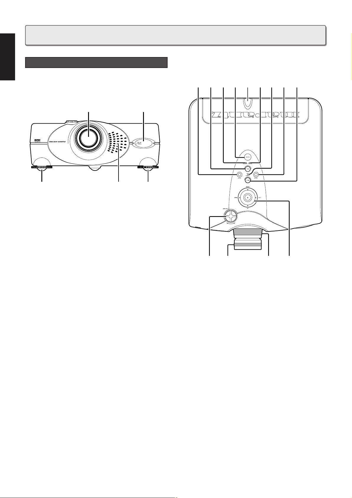
q IR sensor (front and rear)
w Projection Lens
e Ventilation holes
Notes:
• Do not place anything near the ventilation holes to avoid
overheat inside the unit.
• Do not place your hand or objects near the ventilation
holes; the air is coming out.
r Adjustable feet
Adjust the vertical angle of the projector.
t Focus ring
Adjust the picture focus.
y Zoom ring
Adjust the size of the projected image.
u Lens Shift knob
Manually adjust the position of the image vertically.
i POWER key
Press to turn the projector ON or STANDBY mode.
Front and Top
VP-12S1
C
u
s
t
o
m
o
p
t
i
c
s
b
y
M
I
N
O
L
T
A
Z
O
O
M
2
6
.
5
-
3
0
.
7
m
m
r r
q
w
e
q
ty
!2u
i
!5 !4
!1 o !0 !6
!3
PROJECTOR LAYOUT AND FUNCTIONAL OVERVIEW
o POWER ON indicator
Lights up when the power is turned on. Flashes while the
projector goes into standby mode for about one minute.
!0 STANDBY indicator
Lights up when the power is turned off.
!1 MENU key
Display the on-screen menu.
!2 The 3 / 4 / 1 / 2 keys
Control the MENU cursor.
!3 ENTER key
Confirm "Reset All", "Reset Lamp Life", "New Lamp?".
!4 INPUT SELECT key
When the key is pressed, the unit toggles between
COMPONENT, S-VIDEO, VIDEO, and RGB inputs.
!5 FOCUS key
Display a focus pattern.
!6 WARNING/LAMP indicator
Flashes or lights up when something is wrong with the lamp
cover, lamp, fan, or temperature inside the projector.
Page 7
5
INTRODUCTION
ENGLISH
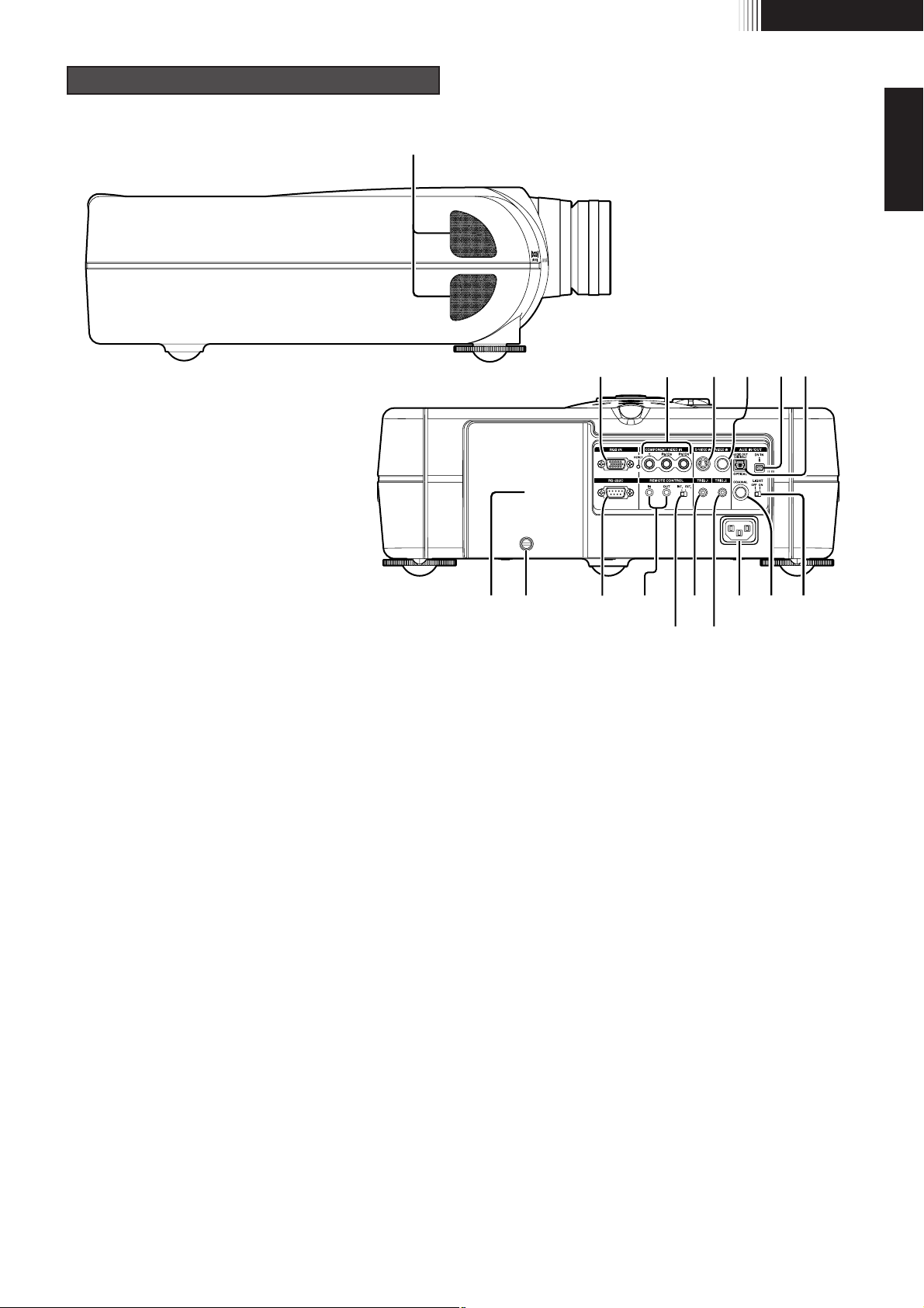
z COMPONENT VIDEO IN
Y, PB
/CB, PR/CR connectors.
Connect the COMPONENT VIDEO output from video
equipment or an A/V processor/receiver with a component
video output.
x S-VIDEO IN
Connect the S-VIDEO output from a video equipment.
c VIDEO IN
Connect the composite video output from a video equipment.
v RGB IN
Connect the analog RGB output from a computer equipment.
b AUX DV IN
Connect the i.LINK(DV-SD format) output from a video
equipment.
n AUX OPTICAL
Connect the optical input from an audio equipment.
Audio out terminal of DV-IN signal.
VP-12S1
zc
m⁄4⁄6⁄5 ⁄0,⁄3 ⁄2
⁄7
x nbv
⁄1.
Right Side and Rear
m AUX AUDIO OUT (DIGITAL)
Connect the COAXIAL input from an audio equipment.
Audio out terminal of DV-IN signal.
, REMOTE CONTROL IN/OUT
By connecting this projector to another Marantz audio
component using a supplied System Control cable, you can
remotely operate the components as a single system.
• When connecting to component with a remote sensor
(such as the SR-14,SR-18,SR-19), be sure to connect the
"REMOTE CONTROL IN" jack of this projector to the
"REMOTE CONTROL OUT" jack of the component with
the remote sensor.
• When connecting to component which is not equipped
with a remote sensor, be sure to connect the component
to the "REMOTE CONTROL OUT" jack of this projector.
. REMOTE switch (EXTERNAL/INTERNAL)
When using this projector independently, set this switch to
"INTERNAL". When using this projector in a system with a
Marantz DVD player or AV Receiver equipped with a remote
sensor, set the switch to "EXTERNAL".
⁄0 TRIG.1(TRIGGER 1)
When the unit is turned on, 12V is output. When the unit is
turned off, no voltage is output. This allows such as a powered
up/down screen,whenever the projector is turned on or off.
Page 8

6
ENGLISH
⁄1 TRIG.2(TRIGGER 2)
Select ON or OFF at each aspect mode, such as Full,
Normal, Zoom, and Through to control screen aspect ratio
with powered up/down dual aspect ratio screen.
Note:
Do not use TRIG.1 and TRIG.2, as the power source.
⁄2 LIGHT ON/OFF
Select ON : The connector panel lights up.
⁄3 RS232C
Connect the RS232C of equipment for external control.
⁄4 AC IN
Connect the supplied AC power code.
⁄5 Lamp cover
⁄6 Lamp cover securing screw
⁄7 Ventilation holes
Notes:
• Do not place anything near the ventilation holes to avoid
overheat inside the unit.
• Do not place your hand or objects near the ventilation
holes; the air is coming out.
Page 9
7
INTRODUCTION
ENGLISH
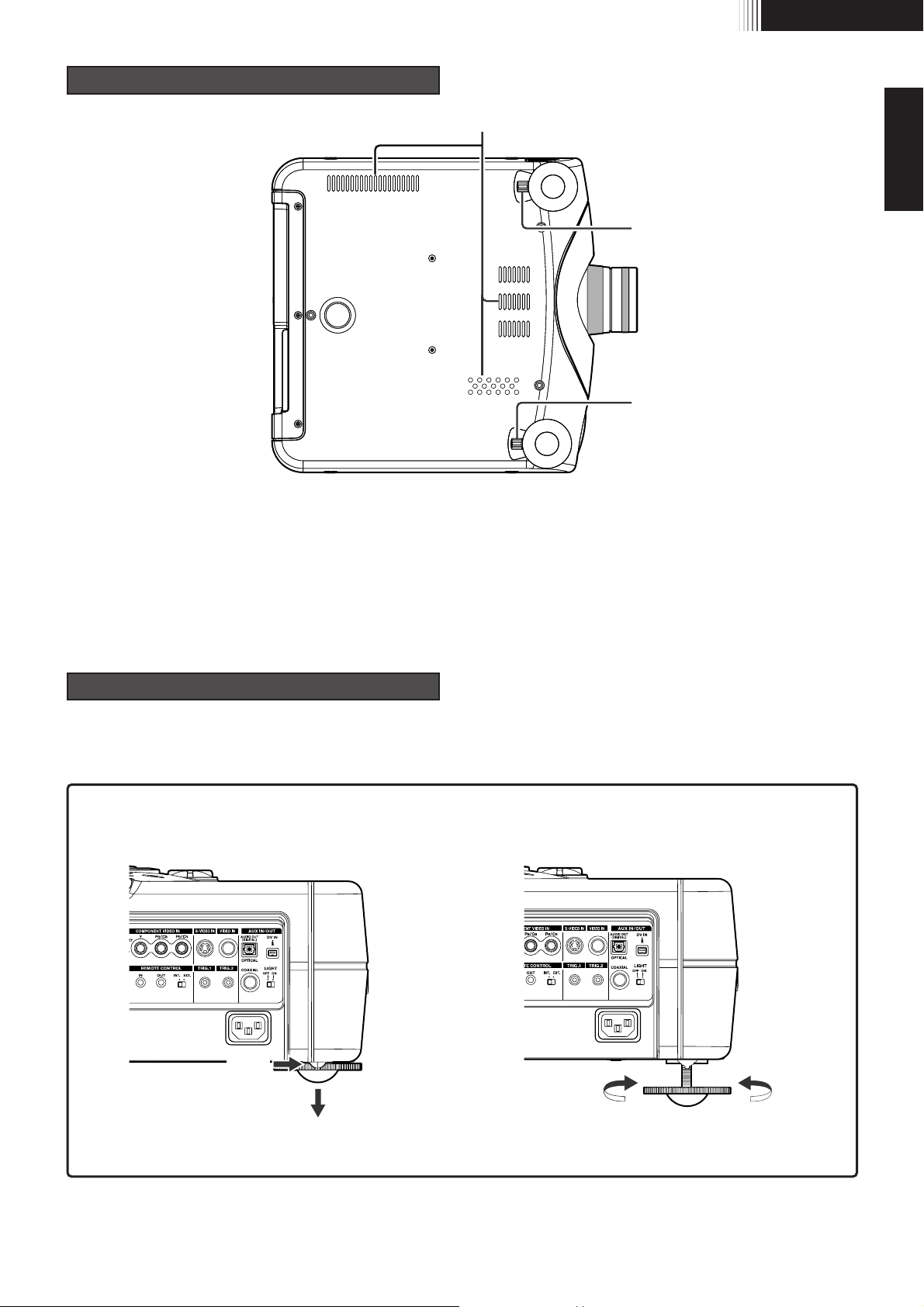
Height Adjustment
How to use adjustable feet and adjustment lever.
(1) Release the adjustable feet. (2) Detail adjustment
PRESS
DOWN
DOWN
UP
Note : Lift the unit up carefully.
q
q
w
Bottom
q Adjustment lever
Lift the projector and turn the adjustment lever right or left.
The adjustable feet will extend from the projector. Then,
release the lever, the adjustable feet is locked.
w Ventilation holes
Notes:
• Do not place anything near the ventilation holes to avoid
overheat inside the unit.
• Do not place your hand or objects near the ventilation
holes; the air is coming out.
Page 10
8
ENGLISH
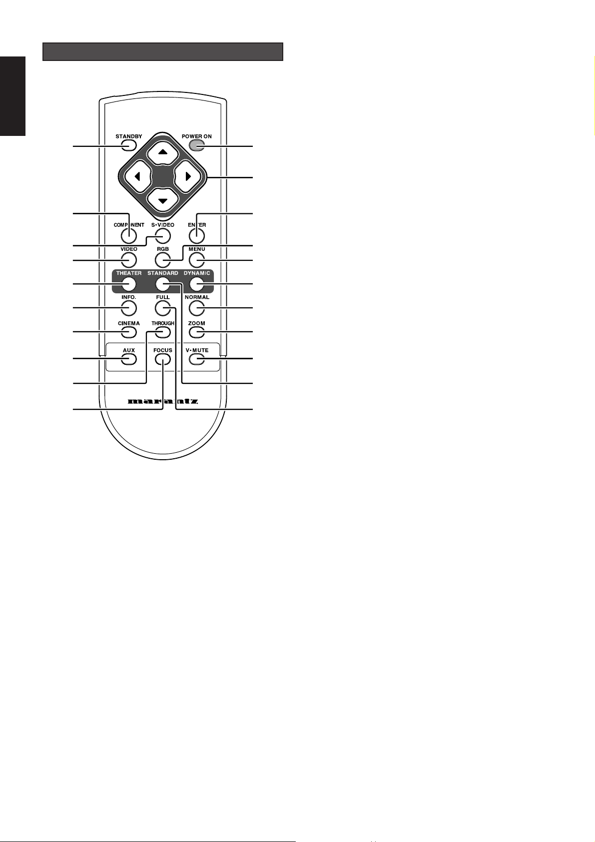
a POWER ON key
Turn the projector on.
s STANDBY key
Turn the projector off.
d 3 / 4 / 1 / 2 keys
Control the MENU cursor.
f ENTER key
Confirm "Reset All", "Reset Lamp Life", "New Lamp?".
g MENU key
Display the on-screen menu.
h COMPONENT key
Select the COMPONENT VIDEO IN signal.
j S-VIDEO key
Select the S-VIDEO IN signal.
k VIDEO key
Select the VIDEO IN signal.
Remote Controller
l RGB key
Select the RGB IN signal.
¡0 THEATER key
Select the Theater picture mode.
When the key is pressed, the mode toggles Theater1,
Theater2, Theater3 and Theater Default.
¡1 STANDARD key
Select the STANDARD picture mode.
When the key is pressed, the mode toggles Standard1,
Standard 2, Standard 3, and Standard Default.
¡2 DYNAMIC key
Select the Dynamic picture mode.
When the key is pressed, the mode toggles Dynamic1,
Dynamic2, Dynamic3 and Dynamic Default.
Note :
If you need discrete command for above picture modes, you
can down load from "www.marantz.com".
¡3 INFO key
Turn the information menu on or off.
¡4 CINEMA key
Press to turn the CINEMA mode – auto 3-2 pull down mode
– on or off.
¡5 NORMAL key
Select NORMAL mode from four aspect ratio modes.
¡6 FULL key
Select FULL mode from four aspect ratio modes.
¡7 ZOOM key
Select ZOOM mode from four aspect ratio modes.
¡8 THROUGH key
Select THROUGH mode from four aspect ratio modes.
¡9 AUX key
Select the AUX IN (DV IN) signal.
™0 FOCUS key
Display a focus pattern.
™1 V-MUTE key
Cuts off the picture.
a
d
g
l
¡2
¡5
¡7
™1
¡1
¡4
s
h
k
¡0
¡3
¡4
¡9
¡8
™0
j
f
PROJECTOR
Page 11

9
INTRODUCTION
ENGLISH
1. Open the cover.
2. Insert batteries (AA).
Make sure to match the + and – marks on the batteries
with inside the battery compartment.
3. Close the cover.
CAUTION
– The available battery types are limited: manganese dry
cell and alkaline dry cell.
– Do not mix different battery types.
– Do not mix old and new batteries.
– Only batteries of the same type are to be used.
– Remove exhausted batteries from the Remote
Controller.
– Do not attempt to recharge non-rechargeable batteries.
– Do not use rechargeable batteries.
– Batteries are to be inserted with the correct polarity.
– The supply terminals are not to be short-circuited.
– Never throw batteries in a fire or attempt to open up its
outer casing.
– If the user does not intend to use the Remote Controller
for a long time, remove the batteries.
– Keep away from heat.
– The effect range of the Remote Controller is approximately
6m.
– Do not be subjected to strong shock.
– Do not be subjected to moisture.
If the unit gets moistured, wipe it off immediately.
– The Remote Controller operation may not function if the
projector’s IR sensors are exposed to direct sun light or
strong artificial light, or if there is an obstacle between
the IR sensors and the Remote Controller.
Preparing the Remote Controller
Page 12

10
ENGLISH
VP-12S1
Adjust the vertical and
horizontal positions of the
projector.
Side view
Flat view
INSTALLATION
Recommended Setting
CAUTION
– For ceiling installation, consult with Marantz authorized dealer.
– Do not look into the lens when the projector is turned on.
It could damage your eyesight.
Horizontal center of the screen
Throw distance
Ceiling
7
Table Top
7
Ceiling Installation
Note : Lens shift position is at Full up.
Page 13

11
SET UP PROCEDURES
ENGLISH
VP-12S1
Distance between the projector and the screen (throw distance)
Screen size
(Diagonal)
Throw distance
Screen
40 inch
60 inch
80 inch
100 inch
120 inch
150 inch
200 inch
250 inch
50
7
/16 inch
1,281 mm
76
9
/16 inch
1,945 mm
102 3/4 inch
2,609 mm
128
7
/8 inch
3,273 mm
155 inch
3,938 mm
194
1
/4 inch
4,934 mm
259
5
/8 inch
6,594 mm
325 inch
8,255 mm
Screen Size
(Diagonal)
16:9 screen
Throw distance
Minimum Maximum
58 11/16 inch
1,491 mm
89 inch
2,260 mm
119
1
/4 inch
3,029 mm
149 9/16 inch
3,798 mm
179
13
/16 inch
4,568 mm
225 1/
4 inch
5,721 mm
300
15
/16
inch
7,644 mm
376
11
/16 inch
9,567 mm
46 1/4 inch
1,172 mm
70
1
/8
inch
1,782 mm
94
3
/16 inch
2,392 mm
118
3
/16 inch
3,001 mm
142
3
/16 inch
3,611 mm
178
3
/16 inch
4,526 mm
238
3
/16 inch
6,050 mm
298
1
/
4 inch
7,575 mm
4:3 screen
Throw distance
Minimum Maximum
53 3/4
inch
1,365 mm
81
9
/16 inch
2,071 mm
109
5
/16 inch
2,777 mm
137 1/
8 inch
3,483 mm
164
15
/16 inch
4,190 mm
206 5/8 inch
5,249 mm
276 3/16 inch
7,014 mm
345
11
/16 inch
8,780 mm
Note : Tolerance ±5 %
Minimum = 15/16 x Screen size – 17/8
Maximum = 11/2 x Screen size – 17/8
Unit : inch
Minimum = 33.21 x Screen size – 47.6
Maximum = 38.46 x Screen size – 47.6
Unit : mm
Minimum = 13/16 x Screen size – 17/8
Maximum = 13/8 x Screen size – 17/8
Unit : inch
Minimum = 30.49 x Screen size – 47.6
Maximum = 35.31 x Screen size – 47.6
Unit : mm
Page 14

12
ENGLISH
You can adjust the image position with the Lens Shift knob.
7
Turn the Lens Shift knob to clockwise :
The image goes up.
• Maximum range to throw up :
Bottom of the image correspond to the center of the
Projection Lens.
7
Turn the Lens Shift knob to counterclockwise :
The image goes down.
• Maximum range to throw down :
Top of the image correspond to the center of the
Projection Lens.
Image Position Adjustment
Clockwise
Up
Counterclockwise
Down
Page 15

13
SET UP PROCEDURES
ENGLISH
When the projecting image is a trapezoid, correct it in
Keystone-V and/or Keystone-H in the Display Menu.
7
Keystone-V(Electronic vertical keystone correction)
Picture Adjust
Setting
Display
Config
Trigger 2
Memory
Keystone V
Keystone H
Auto Adjust
Picture Shift V
Size V
Picture Shift H
Size H
Phase
50
50
50
50
50
50
50
Advanced Setting
7
Keystone-H(Electronic horizontal keystone correction)
Note : Electronic horizontal keystone correction works
properly when the lens shift position is at Full Up.
Page 16

14
ENGLISH
• Press the ZOOM key, the NORMAL key or the FULL key on the remote controller for the 4:3 aspect ratio video source.
• Press the FULL key on the remote controller for 16:9 aspect ratio video source, such as 1080i, 1035i, and 720p video systems.
• Press the FULL key on the remote controller for the squeezed video source.
7
Full mode
The Screen Images in a Wide screen (16:9)
7
Original Source Image
4 : 3 video source
16 : 9 video source
The 16:9 squeezed image is displayed with the correct
aspect.
The 4:3 image is enlarged horizontally.
7
Normal mode
The picture with normal ratio 4:3 is displayed.
7
Zoom mode
The picture with normal ratio 4:3 is enlarged vertically
and horizontally (with same ratio) to the screen size
7
Through mode
Displays the image with the same resolution as the input video source except 1035i, 1080i, and XGA.
Page 17

15
SET UP PROCEDURES
ENGLISH
• Press the ZOOM key, the NORMAL key or the FULL key on the remote controller for the 4:3 aspect ratio video source.
• Press the FULL key on the remote controller for 16:9 aspect ratio video source, such as 1080i, 1035i, and 720p video systems.
• Press the FULL key on the remote controller for the squeezed video source.
7
Full mode
The Screen Images in a 4:3 screen
7
Original Source Image
4 : 3 video source
16 : 9 video source
The 16:9 squeezed image is displayed with the correct
aspect.
The 4:3 image is enlarged horizontally.
7
Normal mode
The picture with normal ratio 4:3 is displayed.
7
Zoom mode
The picture with normal ratio 4:3 is enlarged vertically
and horizontally (with same ratio) to the screen size
7
Through mode
Displays the image with the same resolution as the input video source except 1035i, 1080i, and XGA.
Page 18

16
ENGLISH
DVD
VCR
S-VIDEO OUT
VIDEO OUT
COMPONENT VIDEO OUT
Computer
HD Set Top Box
/ BS Tuner
RGB OUT
RGB OUT
When making connections be sure to:
• Turn off all equipment before making any connections.
• Use the proper cables for each connection.
• Insert the plug properly. Any plugs that are not fully inserted often generate a noise.
When pulling out a cable:
• Be sure to grab the plug, not the cable itself.
CONNECTION
Connections with Video equipments
Connection with a HD-Video or PC
Page 19

17
SET UP PROCEDURES
ENGLISH
Receiver equipment with
a Dolby Digital decoder
DIGITAL AUDIO IN
DV-SD OUT
DV camcoder
Connection with a DV camcoder
Note: DV IN connector is available for DV-SD format of i.LINK(IEEE1394).
Receiver equipment with
a Dolby Digital decoder
REMOTE CONTROL IN
REMOTE CONTROL OUT
External Controller
RS-232C
35mm Mini Plug (Mono)
Ferrite core
Control Adapter cable
Screen
Advanced connection
Page 20

18
ENGLISH
1. Connect the supplied AC power cord.
The STANDBY indicator lights up and the projector
goes into the standby mode.
2. Press the POWER ON key on the remote controller or
the POWER key on the projector.
The POWER indicator lights up.
3. Press the FOCUS key on the remote controller to
display the FOCUS pattern and turn the Focus ring to
make an adjustment. Adjust the focus for the sharpest
image possible to obtain, using focus pattern.
Press the FOCUS key again to clear off the pattern.
4. Turn the Zoom ring to adjust the size of the image.
5. Switch on the equipment connected to the projector.
Press the INPUT SELECT key on the projector or the
COMPONENT key, S-VIDEO key, VIDEO key, or RGB
key on the remote controller.
1. Press the STANDBY key on the remote controller or the
POWER key on the projector.
2. The fan continues to run for a while to reduce internal
heat. The POWER ON indicator flashes in blue and no
key will be active minute. After about one minute
cooling has been provided, the unit turned off and the
STANDBY indicator lights up.
INITIAL SET UP
TO TURN OFF THE POWER
Page 21

19
OPERATIONS
ENGLISH
Adjust the picture to suit own preference by using the Picture
Adjust feature.
7
For a video signal input, the following adjustments
can be made:
NOTE: The user cannot adjust Tint in Component signal
(YC
BCR/YPBPR).
– Contrast
Use
1 / 2 key to adjust.
Use
3 / 4 key to go back to the MENU.
Contrast 50
The following settings can be made:
7
Aspect (Full, Normal, Zoom, Through)
7
High Bright (On, Off)
High Bright ON: Display brightest image.
7
Cinema (Auto, Off)
Cinema mode: The 3-2 pull down for NTSC and the 2-2
pull down for PAL
7
Black Setup (0IRE, 7.5IRE)
Black level adjustment, for adjusting black level by a
video source.
NOTE: Not able to adjust Black Setup in IEEE1394
signal: AUX in signal.
7
Lamp mode (High/Low)
7
Component(Auto, NTSC, PAL, 480p, 540p, 576p,
720p, 1035i, 1080i)
7
Video System(Auto, NTSC, PAL, SECAM)
7
RGB System(Auto, NTSC, PAL, 480p, 540p, 576p,
720p, 1035i, 1080i, VGA)
Picture Adjust
Setting
Display
Config
Trigger 2
Memory
Aspect
High Bright
Cinema
Black Setup
Lamp Mode
Component
Full
Off
Auto
0 IRE
High
Auto
Video System
RGB System
Auto
Auto
Setting
Refer to the on-screen menu for making various adjustments
and settings.
1. Press the MENU key.
The MENU appears.
2. Use 3 / 4 / 1 / 2 keys to select a menu item.
3. Make adjustments in Picture Adjust, Setting, Display,
Configuration, Trigger2, or Memory.
Picture Adjust
Setting
Display
Config
Trigger 2
Memory
Contrast
Brightness
Color
sharpness
Tint
Noise Reduction
Color Temp.
50
50
50
8
0
8
Middle
ITEM
Contrast
Brightness
Color
Sharpness
Tint
Noise Reduction
Color Temp. (Color Temperature)
Adjustments
099
Weak Strong
099
Dark Bright
099
Light Deep
015
Soft Sharp
R50 G50
Purple Green
015
Weak Strong
LMH
Red Blue
OPERATIONS
Picture Adjust
Menu
– Color Temp.
H: Make white more blue.
M: Make white less blue. This setting is approximately
6500 degrees in Kelvin.
L: Make white more reddish.
Color Temp. Low Middle High
NTSC(NTSC-3.58)
: Conventional analog broadcasting used
mainly in USA, Canada, Taiwan, Korea, and
Japan.
PAL(PAL-4.43)
: Conventional analog broadcasting used
mainly in United Kingdom and Germany.
SECAM : Conventional analog broadcasting used
mainly in France and Russia.
480p : Standard digital broadcasting
540p : Special digital broadcasting
(for example: RCA DTC100)
576p : Standard digital broadcasting
720p, 1080i : High Definition digital broadcasting
1035i : Japanese "Hi-Vision" broadcasting
Page 22

20
ENGLISH
The following adjustments can be made:
7
OSD Position (16:9 / 4:3 / Through )
7
Language (English/ German/ French/ Spanish/
Portuguese/ Italian)
7
Ceiling (On/Off)
ON: The picture is reversed horizontally and vertically.
7
Rear (On/Off)
ON: The picture is reversed horizontally.
7
Reset Lamp Life (Yes/No)
7
Reset All (Yes/No)
– OSD Position (16:9 / 4:3 / Through)
Select OSD position from 16:9, 4:3, or Through.
Picture Adjust
Setting
Display
Config
Trigger 2
Memory
OSD Position
Language
Ceiling
Rear
4:3
English
Off
Off
Reset Lamp Life
Reset All
Configuration
7
The following adjustments can be made:
– Keystone H, V
Adjust the trapezoid image to a rectangle image.
– Auto Adjust
Yes : For RGB IN signal, Picture Shift V and H, Size V
and H, and Phase are adjusted automatically.
No : If something wrong with AUTO Adjust, select No,
and adjust Size V, Size H, Picture Shift H, Picture
Shift V, and/or Phase.
– Picture Shift V, H
Adjust the position of the picture. H adjusts the horizontal
position of the picture. V adjusts the vertical position of the
picture.
– Size V, H
Adjust the vertical and horizontal size of the picture.
– Phase
Adjust the phase of the DMD
TM
dots and the computer signal
input from the RGB IN. Adjust the picture to where it looks
clearest.
Picture Adjust
Setting
Display
Config
Trigger 2
Memory
Keystone V
Keystone H
Auto Adjust
Picture Shift V
Size V
Picture Shift H
Size H
Phase
50
50
50
50
50
50
50
Keystone-V (Electronic vertical
keystone correction)
Keystone-H (Electronic horizontal
keystone correction)
Auto Adjust
Picture Shift V
Size V
Picture Shift H
Size H
Phase
ITEM
Down
Small
Left
Small
Backward
Up
Large
Right
Large
Forward
Yes / No
Display
Picture Adjust
Setting
Display
Config
Trigger 2
Memory
Contrast
Brightness
Color
sharpness
Tint
Noise Reduction
Color Temp.
50
50
50
8
0
8
Middle
16 : 9 OSD position
Picture Adjust
Setting
Display
Config
Trigger 2
Memory
Contrast
Brightness
Color
sharpness
Tint
Noise Reduction
Color Temp.
50
50
50
8
0
8
Middle
4 : 3 OSD position
Picture Adjust
Setting
Display
Config
Trigger 2
Memory
Contrast
Brightness
Color
sharpness
Tint
Noise Reduction
Color Temp.
50
50
50
8
0
8
Middle
Through OSD position
Page 23

21
OPERATIONS
ENGLISH
Select 12V DC or 0V from on and off at each aspect mode.
Full, Normal, Zoom, and Through.
On: Output DC 12V.
Off: No output.
This allows such as a powered dual aspect screen according
to the aspect mode.
Picture Adjust
Setting
Display
Config
Full
Normal
Through
Zoom
Off
Off
Off
Off
Trigger 2
Memory
Trigger2
– Reset Lamp Life
When replace the lamp unit, before the Lamp Life becomes
"0" hours need to reset lamp life.
When the user selects “Yes”, the following message appears:
Again, select “Yes”, and press the ENTER key. Then the
lamp life is initialized.
– Reset All
All settings goes to the factory default settings except the
lamp life.
When the user selects “Yes”, the following message appears:
Again, select “Yes”, and press the ENTER key.
Reset All ?
Yes No
Reset Lamp Life ?
Yes No
Recall the stored memory for preference. The unit has three
picture modes: THEATER, STANDARD, and DYNAMIC.
Each picture mode has three picture memories.
– Store memory
Select Memory mode from THEATER, STANDARD, or
DYNAMIC using the Remote Controller or in the above menu.
Display Picture Adjust menu. Adjust any items, and these
figures are automatically stored.
Picture Adjust
Setting
Mode Standard
1
Display
Config
Trigger 2
Memory
Memory
Page 24

22
ENGLISH
Lamp Life
Display the remaining lamp life by pressing the INFO key on
the remote controller.
Notes:
• When the Lamp Life becomes less than 100 hours , it is
recommended to replace the lamp unit. A lamp may be
worn out when the Lamp Life becomes less than 100
hours .
• The projector is designed not to turn on after the lamp use
has exceeded 2000 hours. (Lamp Life 0 HOUR)
If the projector is in use, it will turn off.
3
3 When the lamp life becomes less than 100 hours and the
unit is still on, the remaining lamp life is displayed on the
screen automatically.
3
3 When the lamp life becomes less than 5 hours, the
remaining lamp life is displayed on the screen .
To clear above, press the MENU key.
Warning
Lamp Life 5 Hours
Warning
Lamp Life 100 Hours
Video Input
Memory
Cinema Mode
Noise Reduction
Aspect
Trigger
Lamp Life
Total Hours
COMPONENT
Standard 1
Auto
6
Normal
On
1000 Hours
0 Hour
3
3 When the lamp life has expired (Lamp Life 0 HOURS),
the unit will be immediately turned off, and the WARNING
indicator will light up in red.
Replacing the lamp unit with new one, then use the following
procedure to reset (initialize) the lamp life.
Refer to "Replacing Lamp Unit".
1. Unplug the power cord.
2. Wait about one minute and reconnect the power cord.
3. Press the POWER key. The following message appears
for 120 seconds.
4. Select “Yes”, using the 1 / 2 keys.
5. Press the ENTER key. The lamp life indicator is now
initialized.
New Lamp ?
Yes No
Warning
Lamp Life 0 Hours
Lamp Life and Replace Lamp
Page 25

23
ADDITIONAL INFORMATION
ENGLISH
CAUTION:
• Do not touch the lamp and the lamp unit immediately. It
will be extremely hot. Allow at least one hour for the lamp
to cool down before handling.
• Do not loosen any screws except for those mentioned
below.
• The lamp may break if handled improperly.
• Do not use other than a Marantz replacement lamp unit.
7
How to replace the Lamp Unit
WARNING:
• The lamp itself may get hot. Be careful when handling.
1. Press the POWER key to turn the projector off.
2. Unplug the AC power cord.
3. Wait at least one hour for the lamp and lamp unit to cool
down.
4. Read the caution and warning labels on the unit.
If the lens becomes dirty or smudged, clean it with a soft dry
cloth. Use optical lens cleaners only which are approved for
eyeglasses or cameras. Do not use a dampen cloth, detergent
solution, or thinner. It may damage the lens and remain as
stains.
When replacement parts are required, be sure to inform a
Marantz authorized service center. Use only replacement
parts specified by Marantz. Unauthorized substitutions may
result in fire, electric shock, or other hazards.
And, the warranty may not be guaranteed.
7
Lamp Unit : LU-12VPS1
7
Ceiling Mount KIT : RM-12VPS1
7
Lens : LN-12VPS1
CAUTION:
• For ceiling installation, consult with the Marantz Authorized
dealer.
MAINTENANCE
Replacing Lamp Unit
Cleaning the lens
Replacement parts
Optional accessories
SERIAL NO.
MODEL NO. VP-12S1 / N1S
230V 1.5A 50H
Z
VORSICHT : BEI FALSCHER HANDHABUNG KANN DIE
HOCHDRUCKLAMPE EXPLODIEREN UBERLASSEN SIE NUR
FACHPERSONAL.
CAUTION : HIGH PRESSURE LAMP MAY EXPLODED IF IMPROPERLY
HANDLED. REFER SERVICING TO QUALIFIED SERVICE PERSONNEL.
ATTENTION : LA LAMPE SOUS HAUTE PRESSION PEUT SI ELLE,
N'EST PAS MANIPULEE CORRECTEMENT, CONFIER L'OPERATION A UN
PERSONNEL D'ENTRETIEN QUALIFIE.
CAUTION HOT :
UNPLUG THE POWER CORD AND
WAIT 60 MINUTES BEFORE
CHANGING THE LAMP.
ATTENTION CHAUD :
DEBRANCER LE CORD ON
D'ALIMENTION ET ATENDER 60
MINUTES AVANT DE CHANGER
LAMPE.
WARNUNG HEISS
:
ZIEHEN SIE DEN NETZSTECKER
AB UND WARTEN SIE 60 MINUTEN,
BEVOR SIE DIE GLUHLAMPE
WECHSELN.
M
VORSICHT :
BEI FALSCHER HANDHABUNG KANN DIE
HOCHDRUCKLAMPE EXPLODIEREN UBERLASSEN SIE NUR
FACHPERSONAL.
CAUTION :
HIGH PRESSURE LAMP MAY EXPLODED IF IMPROPERLY
HANDLED. REFER SERVICING TO QUALIFIED SERVICE PERSONNEL.
ATTENTION :
LA LAMPE SOUS HAUTE PRESSION PEUT SI ELLE,
N'EST PAS MANIPULEE CORRECTEMENT, CONFIER L'OPERATION A UN
PERSONNEL D'ENTRETIEN QUALIFIE.
CAUTION HOT :
UNPLUG THE POWER CORD AND
WAIT 60 MINUTES BEFORE
CHANGING THE LAMP.
ATTENTION CHAUD :
DEBRANCER LE CORD ON
D'ALIMENTION ET ATENDER 60
MINUTES AVANT DE CHANGER
LAMPE.
WARNUNG HEISS
:
ZIEHEN SIE DEN NETZSTECKER
AB UND WARTEN SIE 60 MINUTEN,
BEVOR SIE DIE GLUHLAMPE
WECHSELN.
5. Loosen the lamp cover securing screw.
6. Remove the lamp cover.
7. Loosen the two lamp housing screws.
(This projector has a safety switch.)
8. Hold the handle then pull the lamp unit to remove.
9. Install the new lamp unit.
10
. Secure the lamp unit with the two screws.
11
. Close the lamp cover and secure it with a screw driver.
Lamp cover
Page 26

24
ENGLISH
No power
Image is not displayed.
Poor color.
Picture is too dark.
Picture is not clear.
Picture rolls.
The Remote Controller
does not work.
AC power cord is not connected correctly.
Lamp cover is not closed correctly.
A signal cable is not connected correctly.
Selected input is incorrect.
The picture mute is active.
Picture is not adjusted properly.
Lamp life is running short.
Contrast or brightness is not adjusted properly.
Picture is out of focus.
Condensation occurs on the lens.
A signal cable is not properly connected.
Batteries are exhausted.
The distance to the unit is too far.
IR sensor on unit is obstructed.
The “EXTERNAL” position on the connector
panel is selected.
Connect the AC power cord properly.
Close the cover properly.
Connect a signal cable properly.
Select the correct input source .
Press the MUTE key to release the mute.
Adjust the picture in the MENU mode.
Replace the lamp.
Adjust contrast or brightness properly.
Adjust the focus.
Run the projector for about two hours.
Connect a signal cable properly.
Replace batteries.
Reduce the distance between the unit and
the remote control.
Remove any obstacles.
Select the “INTERNAL” position.
Notes:
• If the lamp still does not function after the replacement and initialization of the lamp life, contact Marantz authorized dealer, or
service center.
Possible CauseSymptom Remedy
TROUBLESHOOTING
In case of troubles, check the following before calling for
service:
1. Are the connections made properly ?
2. Are you operating the unit properly, following the
instructions ?
If the unit does not operate properly, check the items shown
in the following table.
If any trouble cannot be solved by the recommendation
below, malfunction of the internal circuitry is suspected;
immediately unplug the AC power cord and contact Marantz
dealer or service center.
ERROR MODE
WARNING/LAMP indicator, POWER ON indicator, and STANDBY indicator diagnose error mode of the projector as follows.
The lamp cover is not
closed properly firmly
The lamp has failed, or
the lamp is completely
worn out.
Temperature around
the lamp unit becomes
unusually high.
Temperature around
the power supply
becomes unusually
high.
The fan inside the
projector has stopped.
Lamp cover
Lamp
Lamp
temperature
Power supply
Fan
ON
ON
Flashing
Flashing
Flashing
OFF
OFF
ON
ON
OFF
Flashing
OFF
Flashing
OFF
ON
Close the cover correctly.
Replace the lamp and
reset lamp life.
Check to see that nothing
is blocking the ventilation
holes, and leave off the
unit for about an hour.
Indicators
Error mode
WARNING
/LAMP
POWER ON STANDBY
Possible Cause Recommendation
Page 27

25
ADDITIONAL INFORMATION
ENGLISH
7
Optical characteristics
Panel 0.85inch 16:9
1,280 x 720 pixels
Digital Micromirror Device
TM
Lamp Super High Pressure 150W
Lens f: 26.5 to 30.7 / F: 3.0
Projection size 40 to 250 inches
Light output 700 ANSI LUMEN typical
7
INPUT/OUTPUT
VIDEO IN RCA x 1
NTSC-3.58/PAL-4.43/SECAM
Composite video 1.0V
p-p/75 Ohm
S-VIDEO IN S-Connector x 1
NTSC-3.58/PAL-4.43/SECAM
S-Video
COMPONENT IN RCA x 3
Y, C
B/PB, CR/PR
RGB/HD IN D-sub M 15 pin x 1
Analog RGB
HD:1080i, 720p, 480p
REMOTE
CONTROLLER IN Mini jack type x 1
REMOTE
CONTROLLER OUT Mini jack type x 1
AC IN 3 Prong Grounding Type
TRIG.1 OUT,
TRIG.2 OUT Mini Jack x 2
Output: DC12V or 0V
RS232C RS232C receptacle plug x 1
AUX. IN IEEE1394 AV receptacle plug x 1
COAXIAL Digital
AUDIO OUTPUT COAXIAL audio data output x 1
OPTICAL Digital
AUDIO OUT OPTICAL audio data output x 1
7
GENERAL
Power requirement
AC 100-120V / 220-240V, 50/60 Hz
Power consumption <250 W
Standby consumption
<3.3 W
Chassis isolation Class-1
Safety UL6500
CSA E60065
EN60950
J60065
IEC60950
EMC FCC Part-15 Class-B
EN55022 Class-B
EN55024
EN61000-3-2,3
Dimensions 405(W) x 471(D) x 155(H)mm
Net weight 13 kg
Operating Temperature 5 to 35 °C
Operating humidity 30 to 85%
Storage Temperature -20 to 60 °C
Storage humidity 30 to 85%
Accessories • Lens cap x 1
• Remote controller x 1
• Batteries x 2
• AC power code x 1
• User Guide x 1
• Control Adapter cable
(Mini jack to RCA) x 1
• Ferrite cores x 2
Specifications may be subjected to change without any prior notice.
SPECIFICATIONS
NO SIGNAL
REPLACE LAMP!
OUT OF RANGE
No input signal.
The lamp has reached the end of its life.
Improper signal feed to the projector.
Properly connect the cables.
Replace the lamp and reset lamp life.
Adjust resolution, V(Hz) : refresh rate of the
equipment, referring to the Timing Chart.
MeaningMessage Remedy
Use the list below to check the message displayed on the screen.
ON SCREEN MESSAGE
Page 28

26
ENGLISH
7
Timing chart
NTSC
PAL-B/G
SECAM
480/60p
576/50p
1035/60i
1080/60i
1080/50i
1080/48i
720/60p
720/50p
720/48p
540/60p
640x350
#1
640x350
#1
640x400
#1
640x400
#1
640x480
640x480
#1
640x480
#1
640x480
#1
800x600
800x600
800x600
#1
800x600
#1
800x600
#1
1024x768
1024x768
1024x768
#1
1024x768
#1
1024x768
#1
768x240
960x287.5
960x287.5
720x480
720x576
1920x518
1920x540
1920x540
1920x540
1280x720
1280x720
1280x720
1920x540
640x350
640x350
640x400
640x400
640x480
640x480
640x480
640x480
800x600
800x600
800x600
800x600
800x600
1024x768
1024x768
1024x768
1024x768
1024x768
59.94 / 60
50
50
59.94 / 60
50
59.94 / 60
59.94 / 60
50
48
59.94 / 60
50
48
59.94 / 60
70
85
70
85
60
72
75
85
56
60
72
75
85
43
60
70
75
85
15.73
15.63
15.63
31.5
31.3
33.8
33.8
28.1
27.0
45.0
37.5
36.0
33.8
31.5
37.9
31.5
53.7
31.5
37.9
37.5
43.3
35.2
37.9
48.1
46.9
53.7
35.5
48.4
56.5
60.0
68.7
I
I
I
P
P
I
I
I
I
P
P
P
P
P
P
P
P
P
P
P
P
P
P
P
P
P
P
P
P
P
P
System Resolution V(Hz
)
H(KHz
)
Scan
Note: The systems marked #1 are not displayed properly.
I : Interlaced signal
P : Progressive signal
Page 29

27
ADDITIONAL INFORMATION
ENGLISH
346.5 mm
344 mm
19.8 mm
110 mm93.5 mm
124.5 mm
127 mm
421 mm
471 mm
132 mm
404.5 mm
222 mm182.5 mm
222 mm182.5 mm
15 - 61.8 mm
: Full up
: Full down
86 mm
76 mm
[Adjustable]
DIMENSIONS
7
TOP
7
FRONT
7
BOTTOM
Page 30

28
ENGLISH
Page 31

COUNTRY COMPANY ADDRESS
ALGERIE Azur 2000 8, Lotissement Ben Hatadi, Alger, Algerie
ARMENIA NGYIG Ltd. 47 A/75 St. Lalaiants, 375000 Yerevan, Armenia
AUSTRALIA Jamo Australia Pty. Ltd., 24 Lionel Road, Mt. Waverley, VIC 3149, Australia
AUSTRIA Huber & Prohaska GmbH Taborstraße 95 / Ladestraße 1, Gebäude Hangartner, A-1200 Wien, Austria
BAHREIN Ambassador Stores P.O. Box 237,141, Government Avenue, Manama,Bahrein
BANGLADESH Target 1078, Ramjoy Mohanja Lane Asadgonj, Chittagong 4000, Bangladesh
BELGIUM Van der Heyden Audio N.V. Brusselbaan 278, 9320 Erembodegem, Belgium
BULGARIA Ariescommerce GmbH Makedonia Blvd. 16, 1606 Sofia, Bulgaria
CANADA Lenbrook Industries Limited 633 Granite Court, Pickering, Ontario
CHINA
Guang Chang Audio International Co., Ltd.
No.38 Yushan Road, ShiQiao, Pan Yu, Guang Dong, China
CYPRUS Empire Hifi systems Ltd. P.O. Box 5604, Nicosia, Cyprus
CZECH REPUBLIC Audio International Sokolska 41, 67902 Rajecko, OKR,Blansko, Czech Republic
DENMARK Audio Nord Dali Allé 1, 9610 Noerager, Denmark
DUBAI V.V.& SONS P.O. Box 105, Dubai, U.A.E.
EGYPT Solimco 9, El Attibaa St. Doki, Cairo, Egypt
ESTONIA HiFi Club Estonia Ehte 4, 90503 Haapsalu, Estonia
F.Y.R.O.M. T.P. KODI ul.Cedomir Kantargiev 21a, Skopje, Former Yugoslavian Republic of Macedonija
FINLAND Audio Nord Uudenmaankatu 4-6, Helsinki SF-00120, Finland
FRANCE Marantz France A division of Marantz Europe B.V., P.O. Box 301, 92 156 Suresnes Cedex, France
GERMANY Marantz Deutschland Hakenbusch 3, 49078 Osnabrück, Germany
GREECE Adamco S.A. 188, Hippocratous Street, 11471 Athens, Greece
HEADQUARTERS EUROPE: Marantz Europe B.V. Building SFF-2, P.O. Box 80002, 5600 JB Eindhoven, The Netherlands
HONG KONG Marantz Asia Ltd. Unit 1706, Metroplaza II, 223 Hing Fong Road, Kwai Fong, N.T., Kowloon, Hong Kong
HUNGARY Infovox Ltd. Terez Krt.31, 1067 Budapest, Hungary
ICELAND ID Electronics Ltd. Armula 38, 108 Reykjavik, Iceland
INDIA NOVA Audio Private 8,Punam Co-op.Society 29/30 Road#5, Union Park MUMBAI 400052, India
IRAN Home Co. 5th floor no 878 Philips Building Enghelab ave, P.O. 11365/7844 Tehran, Iran
IRELAND Marantz Ireland Clonskeagh, Dublin 14, Ireland
ISRAEL Elmor Ltd. 52 Heh Beiyar Street, Kikar Hamedina, Tel Aviv, Israel
ITALY Marantz Italy Via Casati 23, 20052 Monza (Milano), Italy, Servizio Consumatori 1678-20026, Numero Verde
IVORY COAST Hifivoir B.P. 2428, Abidjan 01, Ivory Coast
JAPAN Marantz Japan Inc. 35-1 Sagami Ohno 7-Chome, Sagamihara-shi, Kanagawa 228-8505, Japan
KOREA Mk Enterprises Ltd. 121-210, 2F Shinhan Bldg., 247-17 Seokyo-dong, Mapo-ku, Seoul, Korea
KUWAIT alAlamiah Electronics Intl. P.O. Box 8196, Salmiah 22052, Kuwait
LATVIA Ace Ltd. 61, LacPlesa Str., Riga LV 1011, Latvia
LEBANON AZ Electronics S.A., 1, P.O. Box 11 2833, Beirut, Lebanon
LITHUANIA Accapella Ltd. Ausros, Vartu G/5, Pasazo SKG., 2001 Vilnius, Lithuania
MALAYSIA Wo Kee Hong Electronics Sdn. Bhd. Suite 8.1, Level 8, Menara Genesis, No. 33, Jalan Sultan Ismail, 50250 Kuala Lumpur, Malaysia
MALTA Doneo Co Ltd. 78 The Strand, Sliema SLM07, Malta
MAURITIUS SKR Electronics Ltd. P.O. Box 685, Bell Village, Port Louis, Mauritius
MILITARY MARKET EUROPE PASCO GmbH PO BOX 1280, Sandhausen 69200, Germany
NETHERLANDS Marantz Domestic Sales A division of Marantz Europe B.V., Building SFF2, P.O. Box 80002, 5600 JB Eindhoven, The Netherlands
NEW ZEALAND Wildash Audio Systems 14 Malvern Road, Mt. Albert, Auckland, New Zealand
NORWAY Audio Nord Sandkerveien 64, Oslo 0483, Norway
OMAN Mustafa & Jawad Trading CO. P.O. Box 1918, Ruwi, Oman
POLAND Philips Polska Sp. z.o.o. Al.Jerozolimskie 195b, 02 222 Warszawa, Poland
PORTUGAL Corel2 Comércio de Electrónica Lda., Av. Luís Bívar, No 85 A, 1050 Lisboa, Portugal
PROFESSIONAL EUROPE Marantz Professional Products Kingsbridge House, Padbury Oaks, 575-583 Bath Road, Longford, Middlesex UB7 0EH, U.K.
PROFESSIONAL U.S.A. Marantz Professional Products Distributed by: Superscope Technologies Inc., 1000 Corporate Blvd. Ste.D, Aurora, Illino
QATAR Almana & Partners W.W.L. P.O. Box 49, Doha, Qatar
REUNION Vision + 180 Rue du Marechal Leclerc, 97400 Saint Denis, Ile de la Reunion
ROMANIA Nova Music Entertainment 5, Zagazului Str. Bl.1G,apt.18, sector 1,Bucharest, Romania
RUSSIA Absolute Audio 7/2, Montazhnaya Street, 107497 Moscow, Russia
SAUDI ARABIA Adawlia Univ. Electr. Apl P.O. Box 2154, Alkhobar 31952, Saudi Arabia
SINGAPORE Wo Kee Hong Distribution PTE Ltd. 130 Joo Seng Road, #03-02 Olivine Building, Singapore 368357
SLOVAKIA Bis Audio s.r.o. Nam. SNP 10, 96001 Zvolem, Slovakia
SLOVENIA Bofex Smartinska 152, HALA V/3, 61000 Ljubljana, Slovenia
SOUTH AFRICA Coherent Imports (PTY) Ltd. P.O. Box 1614, Alberton, 1450, South Africa
SPAIN Marantz Spain Martinez Villergas 2, Apartado 2065, Madrid 28027, Spain
SRI LANKA The listening Room Mezzanine Floor, The Landmark 385, Galle Road, Colombo - 3, Sri Lanka
SWEDEN Audio Nord Almedalsvagen 4, Gotenborg 402-23, Sweden
SWITZERLAND Sound Company AG Postfach, 8010 Zürich, Switzerland
SYRIA Hamzeh & Partners Hafez Ibrahim Str. No 117, Damascus Shalan, Syria
TAHITI Covecolor Av. Prince Hinoi, Cours de l'union sacré, P.O. Box 2334, Papeete, Tahiti
TAIWAN Pai-Yuing Co. Ltd. 6th No 148 Sung Kiang Road, Taipei 10429, Taiwan R.O.C.
THAILAND MRZ Standard Co. Ltd. 746-750 Mahachai Road, Wangburapa, Bangkok 10200, Thailand
TUNESIA Societe EDEVIG 40, Avenue du Golfe Arabe, El Menzah, 1004, Tunesia
TURKEY Türk Philips Ticaret A.S. Yukari Dudullu Organize sanayi Bolgesi, 2.Cadde no.28, 81260 Umraniye-Istanbul, Turkey
U.K. Marantz Hifi UK Ltd. Kingsbridge House, Padbury Oaks, 575-583 Bath Road, Longford, Middlesex UB7 0EH, U.K.
U.S.A. Marantz America Inc. 1100 Maplewood Drive Itasca, IL 60143, U.S.A.
YUGOSLAVIA ITM Company Omladinskih Brigada 86, 11070 Belgrade, Yugoslavia
EXPORT Marantz Domestic Sales A division of Marantz Europe BV,Building SFF2, P.O. Box 80002, 5600 JB Eindhoven, The Netherlands
WWW.MARANTZ.COM
Printed in Japan 01/11 MITf 413V851310
is a registered trademark.
R
 Loading...