

Page 1
Service
SR4002
SR4002 /
/L1G/N1G/N1S
N1B/U1B
Manual
INPUTSELECTOR
7.1CH INPUT
STANDBY
POWERON/OFF
SECTION PAGE
1. TECHNICAL SPECIFICATIONS ........................................................................................... 1
2. TECHNICAL DESCRIPTION ............................................................................................... 3
3. POWER AMPLIFIER ADJUSTMENT .................................................................................. 6
4. SERVICE MODE .................................................................................................................. 7
5. SYSTEM ERROR ................................................................................................................. 8
6. UPDATE FIRMWARE .........................................................................................................11
7. WIRING DIAGRAM .............................................................................................................13
8. BLOCK DIAGRAM ..............................................................................................................17
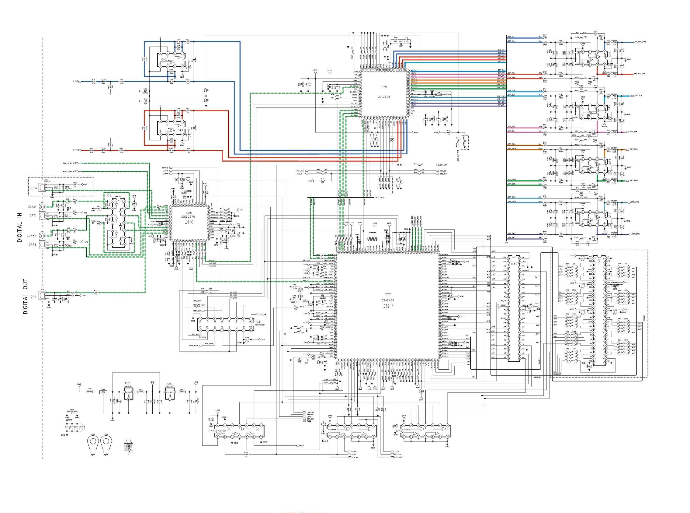
9. SCHEMATIC DIAGRAM .....................................................................................................19
10. PARTS LOCATION ............................................................................................................ 39
11. EXPLODED VIEW AND PARTS LIST ............................................................................... 59
12. MICROPROCESSOR AND IC DATA .................................................................................. 64
13. ELECTRICAL PARTS LIST ................................................................................................ 90
14. ABOUT REPLACE THE MICROPROCESSOR WITH A NEW ONE .............................135
AVSURROUND RECEIVER SR4002
S.SPEAKERB
PHONESSETUPMIC
DISP MULTI AUTO TUNED ST V–OFF NIGHT PEAK ANALOG
SURR
SLEEP
AUTO
SIMPLE
PURE
SURROUND
MODE
AUTO
SETUP
DIRECT
HT-EQ
MENU
DIRECT DISC 6.1 MTX6.1 SPKR B EQ
ENTER
SURROUND
ATT
DIGITAL
DIGITAL
LCR
LFE
PCM
SL S SR
MEMORY
DISPLAY
EXIT
TABLE OF CONTENTS
AV Surround Receiver
VOLUME
DOWN
CLEAR
T-MOD E
BAND
MUTE
AUX1 INPUT
DIGITAL
S-VIDEO
UP
ATT
RLVIDEO
AUDIO
Please use this service manual with referring to the user guide ( D.F.U. ) without fail.
SR4002
Part no. 90M32CW855010
First Issue 2007.08
MZ
Page 2
MARANTZ DESIGN AND SERVICE
Using superior design and selected high grade components,
Only original
MARANTZ
parts can insure that your
MARANTZ
MARANTZ
product will continue to perform to the specifi cations for which
company has created the ultimate in stereo sound.
it is famous.
Parts for your
MARANTZ
ORDERING PARTS :
equipment are generally available to our National Marantz Subsidiary or Agent.
Parts can be ordered either by mail or by Fax.. In both cases, the correct part number has to be specifi ed.
The following information must be supplied to eliminate delays in processing your order :
1. Complete address
2. Complete part numbers and quantities required
3. Description of parts
4. Model number for which part is required
5. Way of shipment
6. Signature : any order form or Fax. must be signed, otherwise such part order will be considered as null and void.
USA
MARANTZ AMERICA, INC
100 CORPORATE DRIVE
MAHWAH, NEW JERSEY 07430
USA
JAPAN
D&M Holdings Inc.
D&M BUILDING, 2-1 NISSHIN-CHO,
KAWASAKI-KU, KAWASAKI-SHI,
KANAGAWA, 210-8569 JAPAN
EUROPE / TRADING
MARANTZ EUROPE B.V.
P. O. BOX 8744, BUILDING SILVERPOINT
BEEMDSTRAAT 11, 5653 MA EINDHOVEN
THE NETHERLANDS
PHONE : +31 - 40 - 2507844
FAX : +31 - 40 - 2507860
CANADA
D&M CANADA INC.
5-505 APPLE CREEK BLVD.
MARKHAM, ONTARIO L3R 5B1
CANADA
KOREA
D&M SALES AND MARKETING KOREA LTD.
CHUNG JIN B/D., #1001,
53-5, WONHYORO 3 GA, YONGSAN-GU,
SEOUL, 140-719, KOREA
PHONE : +82 - 2 - 323 - 2155
FAX : +82 - 2 - 323 - 2154
CHINA
MARANTZ SHANGHAI TRADING LTD.
ROOM.506 SHANGHAI LIGHT INDUSTRY MANSION
1578 NANJING (WEST) ROAD SHANGHAI
CHINA
TEL : 021 - 6248 - 1064
FAX : 021 - 6248 - 3565
NOTE ON SAFETY :
Symbol Fire or electrical shock hazard. Only original parts should be used to replaced any part marked with symbol .
Any other component substitution (other than original type), may increase risk of fi re or electrical shock hazard.
安全上の注意:
がついている部品は、安全上重要な部品です。必ず指定されている部品番号のものを使用して下さい。
SHOCK, FIRE HAZARD SERVICE TEST :
CAUTION : After servicing this appliance and prior to returning to customer, measure the resistance between either primary AC
cord connector pins ( with unit NOT connected to AC mains and its Power switch ON ), and the face or Front Panel of product
and controls and chassis bottom.
Any resistance measurement less than 1 Megohms should cause unit to be repaired or corrected before AC power is applied,
and verifi ed before it is return to the user/customer.
Ref. UL Standard No. 1492.
In case of diffi culties, do not hesitate to contact the Technical
Department at above mentioned address.
070719MZ
Page 3
1. TECHNICAL SPECIFICATIONS
FM TUNER SECTION
Frequency Range ....................................... 87.5 - 108.0 MHz
Usable Sensitivity .................................. IHF 1.8 µV/16.4 dBf
Signal to Noise Ratio .......................... Mono/Stereo 75/70 dB
Distortion ...........................................Mono/Stereo 0.2/0.3 %
Stereo Separation ............................................... 1 kHz 45 dB
Alternate Channel Selectivity ...................... ± 300 kHz 60 dB
Image Rejection ............................................... 98 MHz 70 dB
Tuner Output Level ..................1 kHz, ± 75 kHz Dev 800 mV
AM TUNER SECTION
Frequency Range ............................... 531 - 1602 kHz [ /L/N ]
..................................520 - 1710 kHz [ /U ]
Signal to Noise Ratio .................................................... 50 dB
Usable Sensitivity .......................................... Loop 400 µV/m
Distortion ....................................... 400 Hz, 30 % Mod. 0.5 %
Selectivity ......................................................± 20 kHz 70 dB
Note :
[/K] : PS5072
AUDIO SECTION
Power Output (20 Hz - 20 kHz/THD=0.08%)
Front L&R .................................................. 8 ohms 80 W / Ch
Center ........................................................ 8 ohms 80 W / Ch
Surround L&R ............................................ 8 ohms 80 W / Ch
Surround Back L&R ................................... 8 ohms 80 W / Ch
Front L&R ................................................ 6 ohms 105 W / Ch
Center ...................................................... 6 ohms 105 W / Ch
Surround L&R .......................................... 6 ohms 105 W / Ch
Surround Back L&R ................................. 6 ohms 105 W / Ch
Input Sensitivity/Impedance ...................... 180 mV/ 47 kohms
Signal to Noise Ratio
(Analog Input / Pure Direct) ................................. 105 dB
Frequency Response
(Analog Input / Pure Direct) ........8 Hz - 100 kHz (± 3 dB)
(Digital Input / 96 kHz PCM) .........8 Hz - 45 kHz (± 3 dB)
VIDEO SECTION
Television Format...................................................NTSC/PAL
Input Level/Impedance ..................................1 Vp-p/75 ohms
Output Level/Impedance ................................1 Vp-p/75 ohms
Video Frequency Response .............. 5 Hz to 8 MHz (- 1 dB)
Video Frequency (Component) ........5 Hz to 80 MHz (- 1 dB)
S/N ................................................................................ 60 dB
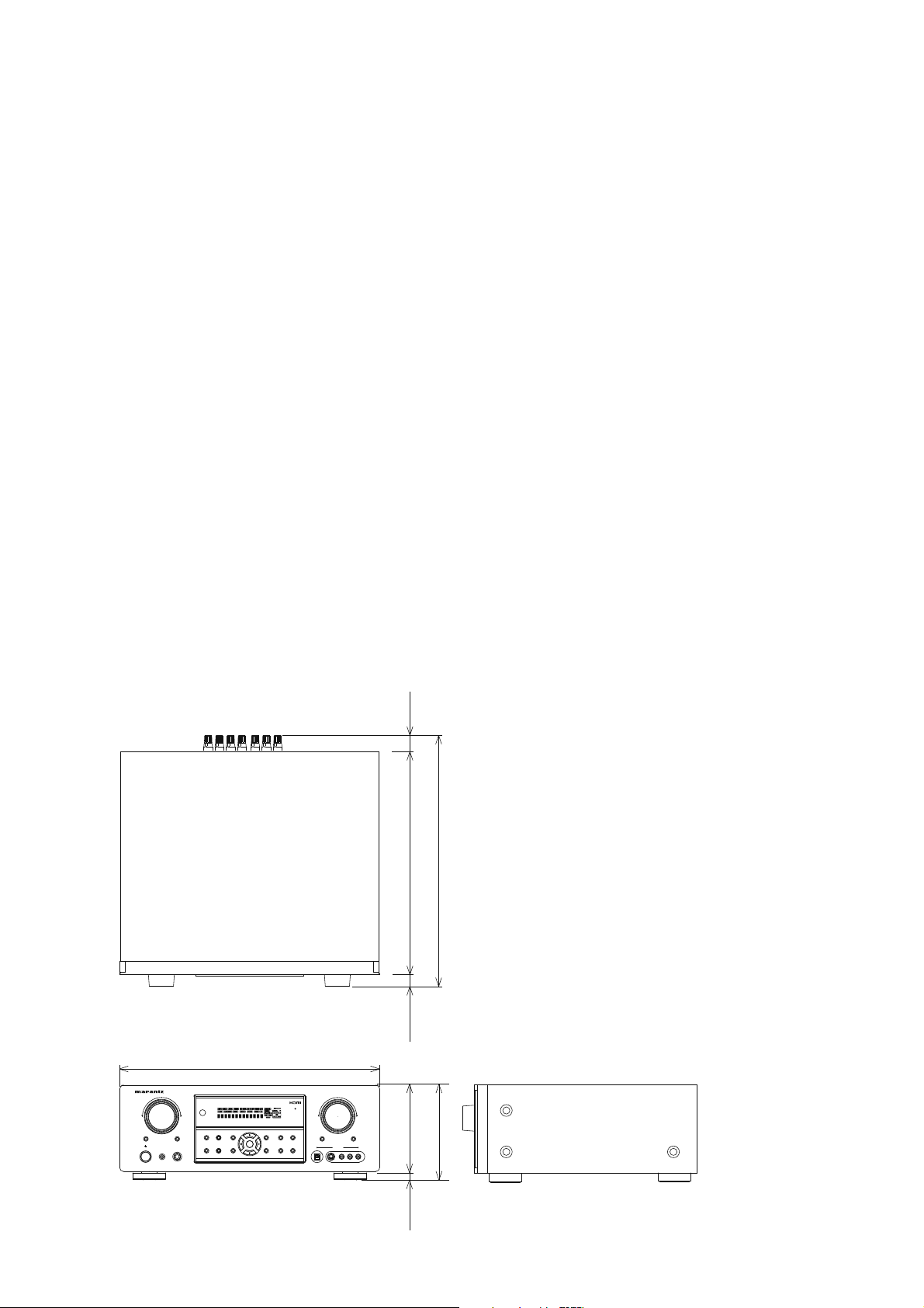
DIMENSIONS
AV SURROUND RECEIVER SR5002
INPUT SELECTOR
MULTI
SPEAKER
MULTI
STANDBY
SETUP MIC
PHONES
POWER ON/STANDBY
17-5/16 ins. (440 mm)
SIMPLE
PURE
SURROUND
MODE
SETUP
DIRECT
AUTO
HT-EQ
MENU
MEMORY
DISPLAY
CLEAR
ENTER
T-MODE
EXIT
BAND
GENERAL
Power Requirement ..............................AC 220 V 50 Hz [ /K ]
(23 mm)
29/32 ins.
.............................. AC 110 V 60 Hz [ /L ]
.........................AC 230 V 50/60 Hz [ /N ]
..............................AC 120 V 60 Hz [ /U ]
Power Consumption ..........................................500 W[ /K/N ]
......................................... 450 W [ /L/U ]
Weight .......................................................11.4 kg (25.1 lbs)
(341 mm)
13-7/16 ins.
(384 mm)
15-1/8 ins.
ACCESSORIES
Remote Control Unit RC5001SR ..........................................1
AAA-size batteries ............................................................... 2
FM Antenna .......................................................................... 1
AM Loop Antenna .................................................................1
Front AUX Jack Cover ..........................................................1
AC Power Cord ..................................................................... 1
Microphone MC-10 ............................................................... 1
(20 mm)
13/16 ins.
VOLUME
UP
DOWN
ATT
MUTE
AUX 1 INPUT
DIGITAL
RLVIDEO
S-VIDEO
AUDIO
5-3/4 ins.
(146 mm)
(160 mm)
6-5/16 ins.
(14 mm)
9/16 ins.
1
Page 4
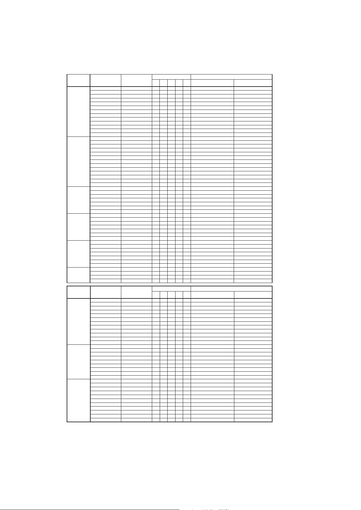
The relation between the selected surround mode and the input signal
The surround mode is selected with the surround mode buttons on SR4002/PS5072 or the remote control unit. However,
the sound you hear is subject to the relationship between the selected surround mode and input signal. That relationship is
as follows;
Surround
Mode
AUTO
SOURCE DIRECT
PURE DIRECT
EX/ES
DOLBY
(PL IIxmovie)
(PL IIx music)
(PL IIx game)
(Pro Logic)
DTS
(Neo:6 Cinema)
(Neo:6 Music)
CS II
Cinema
CS II Music
CS II Mono
Surround
Mode
STEREO
Virtual
Multi Ch.
Stereo
Input Signal Decoding
Dolby Surr. EX Dolby Digital EX OOOOO
Dolby D (5.1ch) Dolby Digital 5.1 OOO - O
Dolby D(2ch) Dolby Digital 2.0 O ----
Dolby D (2ch Surr) Pro Logic II x movie OOOOO
DTS-ES DTS-ES OOOOOdts, ES L, C, R, SL, SR, S, LFE
DTS 96/24 DTS 96/24 OOO - O dts 96/24 L, C, R, SL, SR, LFE
DTS (5.1ch) DTS 5.1 OOO - O dts L, C, R, SL, SR, LFE
Multi Ch-PCM Multi Ch-PCM OOO - O PCM L, C, R, SL, SR, LFE
Multi Ch-PCM 96kHz Multi Ch-PCM 96kHz OOO - O PCM L, C, R, SL, SR, LFE
PCM(Audio) PCM (Stereo) O ---O PCM L, R
PCM 96kHz PCM (96kHz Stereo) O ---O PCM L, R
HDCD PCM (Stereo) O ---O PCM HDCD L, R
Analog Stereo O ---O ANALOG -
Dolby Surr. EX Dolby Digital EX OOOOO
Dolby D (5.1ch) Dolby Digital 5.1 OOO - O
Dolby D (2ch) Dolby Digital 2.0 O ----
Dolby D (2ch Surr) Pro Logic II xmovie OOO --
DTS-ES DTS-ES OOOOOdts, ES L, C, R, SL, SR, S, LFE
DTS 96/24 DTS 96/24 OOO - O dts 96/24 L, C, R, SL, SR, LFE
DTS (5.1ch) DTS 5.1 OOO - O dts L, C, R, SL, SR, LFE
Multi Ch-PCM Multi Ch-PCM OOO - O PCM L, C, R, SL, SR, LFE
Multi Ch-PCM 96kHz Multi Ch-PCM 96kHz OOO - O PCM L, C, R, SL, SR, LFE
PCM (Audio) PCM (Stereo) O - - - - PCM L, R
PCM 96kHz PCM (96kHz Stereo) O - - - - PCM L, R
HDCD PCM (Stereo) O - - - - PCM HDCD L, R
Analog Stereo O - - - - ANALOG Dolby Surr. EX Dolby Digital EX OOOOO
Dolby D (5.1ch) Dolby Digital EX OOOOO
DTS-ES DTS-ES OOOOOdts , ES L, C, R, SL, SR, S, LFE
DTS 96/24 DTS-ES OOOOOdts 96/24 L, C, R, SL, SR, LFE
DTS(5.1ch) DTS-ES OOOOOdts L, C, R, SL, SR, LFE
Multi CH-PCM
AAC (5.1ch) AAC EX OOO - O AAC L, C, R, SL, SR, LFE
Dolby Surr. EX Dolby Digital 5.1 OOO * O
Dolby D (5.1ch) Dolby Digital 5.1 OOO * O
Dolby D (2ch) Pro Logic II x OOOOO
Dolby D (2ch Surr) Pro Logic II x OOOOO
Multi Ch-PCM Multi Ch-PCM + PLIIx OOOOOPCM L, C, R, SL, SR, LFE
PCM (Audio) Pro Logic II x OOOOOPCM L, R
Analog Pro Logic IIx OOOOOANALOG -
DTS-ES DTS 5.1 OOO - O dts, ES L, C, R, SL, SR, S, LFE
DTS 96/24 DTS 96/24 OOO - O dts 96/24 L, C, R, SL, SR, LFE
DTS (5.1ch) DTS 5.1 OOO - O dts L, C, R, SL, SR, LFE
PCM (Audio) Neo:6 OOOOOPCM L, R
Analog Neo:6 OOOOOANALOG -
Dolby D (2ch) Neo:6 OOOOO
Dolby D (2ch Surr) Neo:6 OOOOO
PCM (Audio) CS II OOOOOPCM L, R
Analog CS II OOOOOANALOG -
Dolby D (2ch) CS II OOOOO
Dolby D (2ch Surr) CS II OOOOO
Multi Ch-PCM + Dolby EX
Input Signal Decoding
Dolby Surr. EX Stereo O ---O
Dolby D (5.1ch) Stereo O ---O
Dolby D (2ch) Stereo O ---O*
Dolby D (2ch Surr) Stereo O ---O*
DTS-ES Stereo O ---O dts, ES L, C, R, SL, SR, S, LFE
DTS 96/24 Stereo O ---O dts 96/24 L, C, R, SL, SR, LFE
DTS (5.1ch) Stereo O ---O dts L, C, R, SL, SR, LFE
Multi Ch-PCM Stereo O ---O PCM L, C, R, SL, SR, LFE
PCM (Audio) Stereo O ---O PCM L, R
PCM 96kHz Stereo O ---O PCM L, R
HDCD PCM (Stereo) O ---O PCM HDCD L, R
Analog Stereo O ---O ANALOG -
Dolby Surr. EX Virtual O ----
Dolby D (5.1ch) Virtual O ----
Dolby D (2ch) Virtual O ----
Dolby D (2ch Surr) Virtual O ----
DTS-ES Virtual O ---DTS (5.1ch) Virtual O ----dts L, C, R, SL, SR, LFE
Multi Ch-PCM Virtual O ----PCM L, C, R, SL, SR, LFE
PCM (Audio) Virtual O ----PCM L, R
Analog Virtual O ----ANALOG Dolby Surr. EX Dolby Digital EX OOOOO
Dolby D (5.1ch) Dolby Digital 5.1 OOO - O
Dolby D (2ch) Multi Channel Stereo OOOOO*
Dolby D (2ch Surr) Multi Channel Stereo OOOOO*
DTS-ES DTS-ES OOOOOdts, ES L, C, R, SL, SR, S, LFE
DTS 96/24 DTS 96/24 OOOOOdts 96/24 L, C, R, SL, SR, LFE
DTS (5.1ch) DTS 5.1 OOO - O dts L, C, R, SL, SR, LFE
Multi Ch-PCM Multi Ch-PCM OOO - O PCM L, C, R, SL, SR, LFE
Multi Ch-PCM 96kHz Multi Ch-PCM 96kHz OOO - O PCM L, C, R, SL, SR, LFE
PCM (Audio) Multi Channel Stereo OOOOO*PCM L, R
Analog Multi Channel Stereo OOOOO*ANALOG -
Output Channel Front information display
SLSRSBL
L/R C
OOOOOPCM L, C, R, SL, SR, LFE
Output Channel Front information display
SLSRSBL
L/R C
Signal format indicators Channel status
SubW
SBR
2 DIGITAL EX
2 DIGITAL
2 DIGITAL
2 DIGITAL , 2 SURROUND
2 DIGITAL EX
2 DIGITAL
2 DIGITAL
2 DIGITAL , 2 SURROUND
2 DIGITAL EX
2 DIGITAL
2 DIGITAL EX
2 DIGITAL
2 DIGITAL
2 DIGITAL , 2 SURROUND
2 DIGITAL
2 DIGITAL ,
2 SURROUND
2 DIGITAL
2 DIGITAL , 2 SURROUND
Signal format indicators Channel status
SubW
SBR
2 DIGITAL EX
2 DIGITAL
2 DIGITAL
2DIGITAL , 2 SURROUND
2 DIGITAL EX
2 DIGITAL
2 DIGITAL
2 DIGITAL , 2 SURROUND
dts, ES L, C, R, SL, SR, S, LFE
2 DIGITAL EX
2 DIGITAL
2 DIGITAL
2 DIGITAL , 2 SURROUND
L, C, R, SL, SR, S, LFE
L, C, R, SL, SR, LFE
L, R
L, R, S
L, C, R, SL, SR, S, LFE
L, C, R, SL, SR, LFE
L, R
L, R, S
L, C, R, SL, SR, S, LFE
L, C, R, SL, SR, LFE
L, C, R, SL, SR, S, LFE
L, C, R, SL, SR, LFE
L, R
L, R, S
L, R
L, R, S
L, R
L, R, S
L, C, R, SL, SR, S, LFE
L, C, R, SL, SR, LFE
L, R
L, R, S
L, C, R, SL, SR, S, LFE
L, C, R, SL, SR, LFE
L, R
L, R, S
L, C, R, SL, SR, S, LFE
L, C, R, SL, SR, LFE
L, R
* : Depending on the particular setup, there may be differences compared to the information contained in
these tables.
O* : When L/R (FRONT Speaker) = SMALL.
Notes:
• Dolby Digital (2 ch: Lt/Rt): signal with Dolby
Surround fl ag Speakers are full set.
• No sound outputs from the surround speaker, center
speaker and subwoofer if the DVD disc has no
surround data.
Abbreviations
L/R : Front speakers
C : Center speaker
SL/SR : Surround speakers
SBL/SBR : Surround Back speakers
SubW : Sub woofer speaker
2
Page 5

2. TECHNICAL DESCRIPTION
DESCRIPTION
Manufactured under license under U.S. Patent
#’s: 5,451,942; 5,956,674; 5,974,380; 5,978,762;
6,226,616; 6,487,535; 7,003,467 & other U.S. and
worldwide patents issued & pending. DTS, DTS
Digital Surround, ES, and Neo:6 are registered
trademarks and the DTS logos, Symbol and DTS
96/24 are trademarks of DTS, Inc. © 1996-2007 DTS,
Inc. All Rights Reserved.
• dts Digital Surround
DTS was introduced in 1994 to provide 5.1 channels of
discrete digital audio into home theater systems.
DTS brings you premium quality discrete multichannel
digital sound to both movies and music.
DTS is a multichannel sound system designed to
create full range digital sound reproduction.
The no compromise DTS digital process sets the
standard of quality for cinema sound by delivering
an exact copy of the studio master recordings to
neighborhood and home theaters.
Now, every moviegoer can hear the sound exactly as
the moviemaker intended.
DTS can be enjoyed in the home for either movies or
music on of DVD’s, LD’s, and CD’s.
• dts Neo:6
The advantages of discrete multichannel systems
over matrix are well known.
But even in homes equipped for discrete multichannel,
there remains a need for high-quality matrix decoding.
This is because of the large library of matrix surround
motion pictures available on disc and on VHS tape; and
analog television broadcasts.
The typical matrix decoder of today derives a center
channel and a mono surround channel from twochannel matrix stereo material. It is better than a
simple matrix in that it includes steering logic to
improve separation, but because of its mono, bandlimited surround it can be disappointing to users
accustomed to discrete multichannel.
Neo:6 offers several important improvements as
follow,
• Neo:6 provides up to six full-band channels of
matrix decoding from stereo matrix material. Users
with 6.1 and 5.1 systems will derive six and fi ve
separate channels, respectively, corresponding to
the standard home-theater speaker layouts.
Neo:6 technology allows various sound elements
•
within a channel or channels to be steered
separately, and in a way which follows naturally
from the original presentation.
•
Neo:6 offers a music mode to expand stereo nonmatrix
recordings into the fi ve- or six-channel layout, in a way
which does not diminish the subtlety and integrity of
the original stereo recording.
• dts Digital Surround ES
DTS-ES Extended Surround is a new multichannel
digital signal format developed by Digital Theater
Systems Inc. While offering high compatibility with the
conventional DTS Digital Surround format, DTS-ES
Extended Surround greatly improves the 360-degree
surround impression and space expression thanks
to further expanded surround signals. This format
has been used professionally in movie theaters since
1999.
In addition to the 5.1 surround channels (FL, FR, C,
SL, SR and LFE), DTS-ES Extended Surround also
offers the SB (Surround Back) channel for surround
playback with a total of 6.1 channels. DTS-ES
Extended Surround includes two signal formats with
different surround signal recording methods, as DTSES Discrete 6.1 and DTS-ES Matrix 6.1.
• dts Digital Surround 96/24
The stereo CD is a 16-bit medium with sampling at
44.1 kHz. Professional audio has been 20- or 24-
bit for some time, and there is increasing interest
in higher sampling rates both for recording and for
delivery into the home. Greater bit depths provide
extended dynamic range. Higher sampling rates
allow wider frequency response and the use of antialias and reconstruction fi lters with more favorable
aural characteristics.
DTS 96/24 allows for 5.1channel sound tracks to be
encoded at a rate of 96kHz/24bits on DVD-Video
titles.
When DVD-video appeared, it became possible to
deliver 24-bit, 96 kHz audio into the home, but only in
two channels, and with serious limitations on picture.
This capability has had little use.
DVD-audio allows 96/24 in six channels, but a
new player is needed, and only analog outputs are
provided, necessitating the use of the D/A converters
and analog electronics provided in the player.
DTS 96/24 offers the following:
1. Sound quality transparent to the original 96/24
master.
3
Page 6

Full backward compatibility with all existing
2.
decoders. (Existing decoders will output a 48 kHz
signal)
3. No new player required: DTS 96/24 can be carried
on DVD-video, or in the video zone of DVD-audio,
accessible to all DVD players.
4. 96/24 5.1-channel sound with full-quality fullmotion video, for music programs and motion
picture soundtracks on DVD-video.
Dolby Pro Logic IIx is fully compatible with Dolby
Surround Pro Logic technology and can optimally
decode the thousands of commercially available
Dolby Surround encoded video cassettes and
television programs with enhanced depth and
spatiality. It can also process any high-quality
stereo or Advanced Resolution 5.1-channel music
content into a seamless 6.1- or 7.1-channel listening
experience.
Dolby Digital identifi es the use of Dolby Digital audio
coding for such consumer formats as DVD and DTV.
As with fi lm sound, Dolby Digital can provide up
to fi ve full-range channels for left, center, and right
screen channels, independent left and right surround
channels, and a sixth (“.1”) channel for low-frequency
effects.
Dolby Surround Pro Logic II is an improved matrix
decoding technology that provides better spatiality
and directionality on Dolby Surround program
material; provides a convincing three-dimensional
soundfi eld on conventional stereo music recordings;
and is ideally suited to bring the surround experience
to automotive sound. While conventional surround
programming is fully compatible with Dolby Surround
Pro Logic II decoders, soundtracks will be able to be
encoded specifi cally to take full advantage of Pro
Logic II playback, including separate left and right
surround channels. (Such material is also compatible
with conventional Pro Logic decoders.)
Dolby Digital EX creates six full-bandwidth output
channels from 5.1-channel sources. This is done
using a matrix decoder that derives three surround
channels from the two in the original recording. For
best results, Dolby Digital EX should be used with
movies soundtracks recorded with Dolby Digital
Surround EX.
About Dolby Pro Logic IIx
Dolby Pro Logic IIx technology delivers a natural
and immersing 7.1-channel listening experience
to the home theater environment. A product of
Dolby’s expertise in surround sound and matrix
decoding technologies, Dolby Pro Logic IIx is a
complete surround sound solution that maximizes
the entertainment experience from stereo as well as
5.1-channel encoded sources.
The Dolby Headphone technology provides a
surround sound listening experience over headphones.
When listening to multichannel content such as DVD
movies over headphones, the listening experience
is fundamentally different than listening to speakers.
Since the headphone speaker drivers are covering
the pinna of the ear, the listening experience differs
greatly from traditional speaker playback. Dolby
utilizes patented headphone perspective curves to
solve this problem and provides a non-fatiguing,
immersive, home theater listening experience. Dolby
Headphone also delivers exceptional 3D audio from
stereo material.
Manufactured under license from Dolby Laboratories.
“Dolby”, “Pro Logic”, and the double-D symbol are
trademarks of Dolby Laboratories.
Circle Surround II (CS-II ) is a powerful and versatile
multichannel technology. CS-II is designed to enable
up to 6.1 multichannel surround sound playback
from mono, stereo, CS encoded sources and other
matrix encoded sources. In all cases the decoder
extends it into 6 channels of surround audio and a
LFE/subwoofer signal. The CS-II decoder creates a
listening environment that places the listener “inside”
music performances and dramatically improves
both hi-fi audio conventional surround-encoded
video material. CS-II provides composite stereo rear
channels to greatly improve separation and image
positioning – adding a heightened sense of realism
to both audio and A/V productions.
4
Page 7
CS-II is packed with other useful feature like dialog
clarity (SRS Dialog) for movies and cinema-like bass
enrichment (TruBass). CS-II can enable the dialog
to become clearer and more discernable in movies
and it enables the bass frequencies contained in
the original programming to more closely achieve
low frequencies – overcoming the low frequency
limitations of the speakers by full octave.
Circle Surround II, Dialog Clarity, TruBass, SRS and
symbol are trademarks of SRS Labs, Inc.
Circle Surround II, Dialog Clarity and TruBass
technology are incorporated under license from SRS
Labs, Inc.
HDCD® (High Defi nition Compatible Digital ®) is a
patented process for delivering on Compact Disc the
full richness and details of the original microphone
feed.
HDCD encoded CDs sound better because they are
encoded with 20-bits of real musical information as
compared to 16-bits for all other CDs.
HDCD overcomes the limitation of the 16-bit CD
format by using a sophisticated system to encode
the additional four bits onto the CD while remaining
completely compatible with the CD format.
When listening to HDCD recordings, you hear more
dynamic range, a focused 3-D sound stage, and
extremely natural vocal and musical timbre. With
HDCD, you get the body, depth and emotion of the
original performance not a fl at, digital imitation.
HDCD system manufactured under license from
Microsoft. This product is covered by one or more
of the following: In the United States 5,479,168
5,638,074 5,640,161 5,808,574 5,838,274 5,854,600
5,864,311 5,872,531 and in Australia 669,114 with
other patents pending.
HDMI, the and High-Defi nition Multimedia
Interface are trademarks or registered trademarks of
HDMI Licensing LLC.
5
Page 8
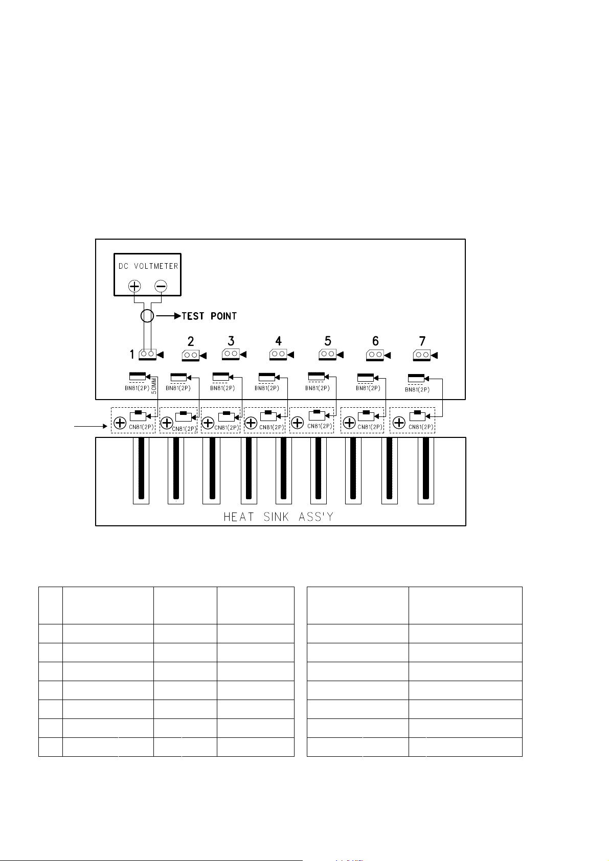
3. POWER AMPLIFIER ADJUSTMENT
Idling Current Alignment
1. Each of the measurement points are provided with the two test points. Set a digital Voltage meter to DC voltage input,
connect the meter to the test points at both contact points.
2. After the setup above, turn on the main switch.
3. Adjust variable resistors (VR81 - VR87) according to the digital voltmeter readings. The target setting value is the
following table for each channels.
Settings :
Master Volume — Minimum
Speaker out — No Load
Top lid — OPEN
MAIN PWB
CUP11999
CN63(2p) CN61(2p) CN65(2p) CN67(2p) CN62(2p) CN66(2p) CN64(2p)
TR BIAS
VR83 or
VR8x
VR81 or
VR8x
VR85 or
VR8x
PWB
No.
Channel
Measuremet
Alignment
Point Point
Surround Left CN63 VR83 or VR8x
1
Center CN61 VR81 or VR8x
2
VR87 or
VR8x
VR82 or
VR8x
Time Table of Idling Current RiseDC voltmeter........Connect to CN6x
After Turning ON
VR86 or
VR8x
5 min
10 min
VR84 or
VR8x
Measurement Voltage
(CN6x)
5 mV ± 0.5 mV
5 mV ± 0.5 mV
Surround Right CN65 VR85 or VR8x
3
Front Left CN67 VR87 or VR8x
4
Surroud Back Left CN62 VR82 or VR8x
5
Front
6
7
Right
Surroud Back Right
CN66 VR86 or VR8x
CN64 VR84 or VR8x 5 mV ± 0.5 mV60 min
20 min
30 min
40 min
50 min
6
5 mV ± 0.5 mV
5 mV ± 0.5 mV
5 mV ± 0.5 mV
5 mV ± 0.5 mV
Page 9
4. SERVICE MODE
Microprocessor (IC11), DSP ROM(IC40 )Version and FLD Seg ment Check Mode.
1. While the power is on, ATT, EXIT and 7.1CH INPUT but tons si mul ta neous ly more than 3 seconds.
The FL display shows "SERVICE MODE" for 2 seconds then shows the model name.
SERV I CE MODE
SR4 0 0 2
2. Press 7.1CH INPUT button, The software version of the mi cro pro ces sor (IC11) is displayed in the format below.
V 070531 1N
Year
3. Press 7.1CH INPUT button again, The software Serial Number that is written in the factory is displayed.
MZ XXXXXXXXX
4. Press 7.1CH INPUT button again, The software Type Number is displayed.
SOF T TYPE XX
5. Press 7.1CH INPUT button again, The Code Group Type Num ber is displayed.
CODE TYPEXXXX
6. Press 7.1CH INPUT button again, The left half, right half and center of the label area in the FLD light on and off each
other.
7. Press 7.1CH INPUT button again, The segments of the char ac ter area in the FLD flick in checker pattern.
8. Press 7.1CH INPUT button again, All the FL segments turns off.
9. Press 7.1CH INPUT button again. Every time 7.1CH INPUT button is pressed, DSP code is indicated in turn from NO.1
to NO.13.
Month Date Dest.
(Dest. : Destination)
(XX is displayed in Hex)
(XX is displayed in Hex)
(XXXX is displayed in Hex)
PS5 072
CD01 02060105
SIGDev. TYP Ver.No.
No. : DISP CODE ID Dev. : Device ID SIG. : CODE SIG ID
TYP. : CODE TYPE ID Ver. : Version
10. Press 7.1CH INPUT button again to quit this mode.
Note :
Step4, 5 is to check if CPU software is capable of DSP code. "Software Type No" is to show what "DSP Code Group" CPU is
capable of. And vice versa.
Step 9 is to manage the 16 codes for DSP.
• When the unit is once turned into Service Mode, the unit keeps this mode until the main power is turned off. (Turn ing
into stand-by mode does not make it quit from Service Mode.) When the unit quits from Service Mode, In for ma tion in the
memory is also cleared and the unit returns to the status when it is out from the factory.
Product Reset
To reset the back up memory of the unit into the default sta tus, follow the procedure below.
1. Turn of the unit and press ATT and 7.1CH INPUT button si mul ta neous ly more than 3 seconds.
2. After "DEFAULT" is displayed on FLD, power is turned off once and turned of again, EEPROM is cleared to the de fault
status, microprocessor is reset and the unit returns to the nor mal status.
Note :
When the unit is shipped from the factory, the pro ce dure above must be done to set the unit to initial status after the
tests.
7
Page 10

5. SYSTEM ERROR
1. Trouble in EEP-ROM (INPUT PWB / IC12) Interface
CHECK E 2 P I F
• If the communication error that ACK did not return by communication with EEP-ROM(INPUT PWB / IC12) occurred 2
seconds and more.
CHECK POINTS OF SCHEMATIC
1. Turn the power on. Are the IIC Clock Line (IC11/22pin-IC12/6pin) normal ?
2. Turn the power on. Are the IIC Data Line (IC11/23pin-IC12/5pin) normal ?
3. Is 5VL(+5V) voltage supplied to 8pin of IC12 ?
4. When no problem to the above 1-3, please replace IC12
2. Trouble in +5V Supply
CHECK POW5
• If 5VD(+5V) inputted into 68pin of IC11 is trouble and the following the fault of 1-4.
CHECK POINTS
1. Turn the power on. Is 5VD(+5V) voltage supplied to CN98/1pin and CN98/2pin of INPUT PWB.
2. Is the signal of IC11 "H" ? 29pin(Power Amp Fail)="H". (When 2 second or more "L" state is continuing to 29pin,
Abnormalities have occurred in the Power Amp circuit.)
3. Is the signal of IC11 "H" ? 66pin(Power Line Fail)="H". (When 2 second or more "L" state is continuing to 66pin,
Abnormalities have occurred to +/-12V power supply or the power supply for Power Amp.)
4. Is the signal of IC11 "H" ? 112pin(Power Down)="H". (When 2 second or more "L" state is continuing to 112pin,
Abnormalities have occurred to in IC96 and around IC 96 circuit of MAIN PWB
3. Trouble in Protection
PROTECT
• When unusual states, such as overload of Power Amp and DC output, are detected. The unusual detection method is the
following.
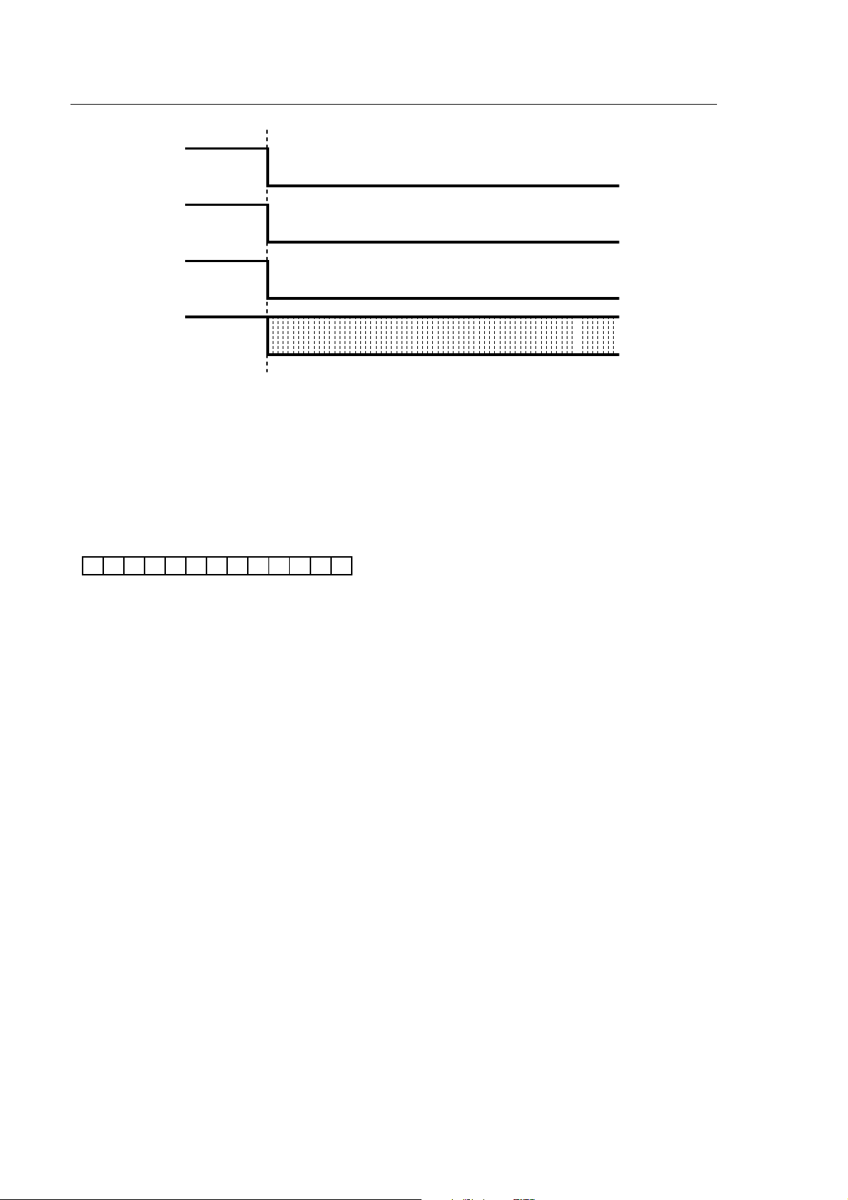
A. When "L" is detected in IC11 29pin(Power Amp Fail), the set is put into the state of STANDBY. At this time, when the
detection time of 29pin is less than 200msec, STANDBY LED on Front Panel is put into the state of blinking at 0.5sec
intervals. After the AC code is pulled out and opened once to make it to power supply ON again when entering this state,
it does with the remote control or Standby button of Front Panel.
8
Page 11
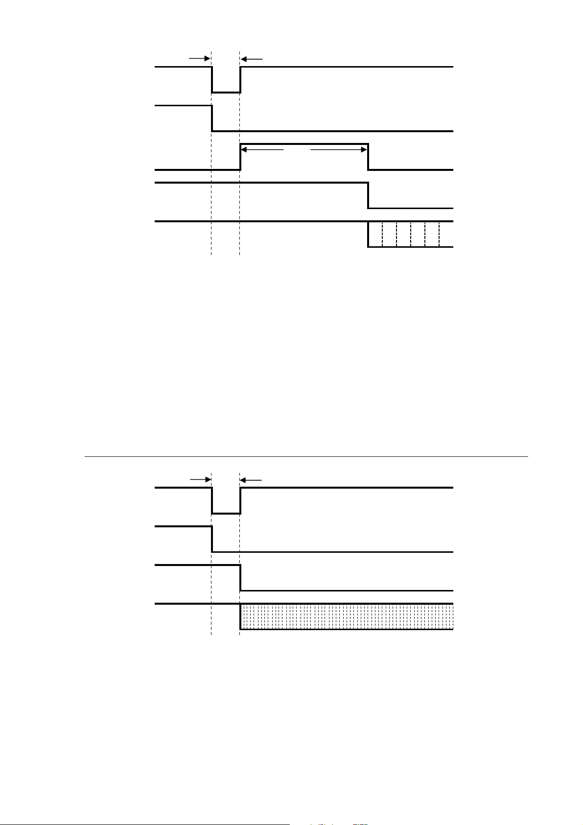
Less than 200msec
Power Amp Fail
SPK Relay Relay off
FL Display 2 sec
"PROTECT" Display on FL
STANDBY
STANDBY LED
CHECK POINTS OF SCHEMATIC
1. When trouble is caused in Power Amp, it repairs.
2. When trouble is not found in Power Amp, it is confirmed whether there are in the disconnection and the detector circuit of
the pattern of IC11 29pin (Power Amp Fail) abnormalities.
STANDBY LED OFF
0.5sec blinking
4. Below is PROTECT MODE which does not display "PROTECT"
A. When "L" is detected in IC11 29pin(Power Amp Fail), the set is put into the state of STANDBY. At this time, when
the detection time of 29pin is longer than 200msec, STANDBY LED on Front Panel is put into the state of blinking at
0.125sec intervals. When this condition, The operation which enters FACTORY MODE is done, PROTECT MODE
release is performed and it Power ON once again.
SR4002/PS5072 : S.SPEAKER B + ATT + EXIT Press button 3sec
SR5002 : MULTI SPK + ATT + EXIT Press button 3sec
A set is broken in the flash state of the 0.125sec interval, so please never make the user do this release operation.
More than 200msec
Power Amp Fail
SPK Relay Relay off
STANDBY
STANDBY LED
STANDBY LED OFF
0.125sec blinking
CHECK POINTS OF SCHEMATIC
1. When trouble is caused in Power Amp, it repairs.
2. When trouble is not found in Power Amp, it is confirmed whether there are in the disconnection and the detector circuit of
the pattern of IC11 29pin (Power Amp Fail) abnormalities.
B. When "L" is detected in IC11 66pin (Power Line Fail), (L=less than 3.5V) the set is put into the state of STANDBY.
STANDBY LED on Front panel. is put into the state of blinking at 0.125sec intervals. When this condition, The operation
which enters FACTORY MODE is done, PROTECT MODE release is performed and it Power ON once again.
SR4002/PS5072 : S.SPEAKER B + ATT + EXIT Press button 3sec
9
Page 12
SR5002 : MULTI SPK + ATT + EXIT Press button 3sec
A set is broken in the flash state of the 0.125sec interval, so please never make the user do this release operation.
Power Line Fail
SPK Relay Relay off
STANDBY
STANDBY LED
STANDBY LED OFF
0.125sec blinking
CHECK POINTS OF SCHEMATIC
1. Abnormality confirms whether to the +/- power supply for Power Amp.
2. Abnormality confirms whether to +/-12V power supply.
3. When trouble is not found in the power supply circuit, it is confirmed whether there are in the disconnection and the
detector circuit of the pattern of IC11 66pin (Power Line Fail) abnormalities.
5. Trouble in DSP Communication
CHECK DSP ROM
• When the communication abnormality of DSP(IC27) and the microcomputer(IC11) is detected or inside contents of
ROM(IC40) of DSP unmatched, it display it.
1. Conform power supply voltage of IC27/IC40 Vcc/Vdd. When it is an abnormal voltage, the power supply is repaired.
2. It is confirmed that IC11 74pin(DSP DOUT Line) is normal at the time of the Power ON
3. It is confirmed that IC11 75pin(DSP DIN Line) is normal at the time of the Power ON
4. It is confirmed that IC11 76pin(DSP CLK Line) is normal at the time of the Power ON
5. It is confirmed that IC11 80pin(REQ1 Line) is normal at the time of the Power ON
6. It is confirmed that IC11 81pin(REQ2 Line) is normal at the time of the Power ON
7. When IC11 74pin-76pin and 80, 81 pin are abnormal, disconnection and defective solder etc. of the pattern are
confirmed
10
Page 13
6. UPDATE FIRMWARE
SR
C
SBR
SBL
L
R
SSPEAKERSYSTEMS : 6-8OHMS
LL
R
IN
OPT
DIGITALOUT
(
AUX2
)
7.1CHINPUT
SBL
SBR
R
L
FM
(
75
)
GNDAMAM
C
R
/
PRC
B
/
P
B
Y
ANTENNA
DIGITALIN
OUT
IN
/CD/CDR
OUTININ
TAPE
VCR
DVDTVTV
AUDIO
DSS
OUT
MODELNO. SR4002
C
R
/
PP
R
C
B
/
P
B
Y
DSS
DVD
VCRIN
VCROUT
MONITOROUT
INPUT
1
INPUT
2
S-VIDEO
VIDEO
PREOUT
ACOUTLET
230V 50/60Hz
SWITCHED
0.65A150W
INPUT2 OUTPUTINPUT 1
HDMIVer 1.1
CENTER
FRONT
SURROUNDBACK
S.SPEAKER B
SURROUND
21
43
ACIN
MONITOR
OUT
INPUT
3
COMPONENT
VIDEO
OUT
REMOTECONT.
Software for CPU and DSP can be updated.
Have Update software and update data.
DATA UPDATE KIT
cable
CN83
(
)
FM
75
ANTENNA
LLSLSLCCSBL
L
R
RRSRSRSWSWSBR
(
)
AUX2
7.1CHINPUT
SLSLSBL
L
RRSR
PREOUT
INPUT
VIDEO
S-VIDEO
GND
C
SWSWSBR
TVTVDVD
VCRIN
VCROUT
ININOUT
VCR
DVD
RRL
FRONT
1
INPUT
2
Y
DSS
MONITOROUT
OUT
TAPE
DSS
AUDIO
LLR
SURROUNDBACK
S.SPEAKER B
SPEAKERSYSTEMS : 6-8OHM
C
R
/
C
B
/
P
B
IN
CD
R
SU
DATA UPDATE KIT
RS232C Dsub-9 pin cable
PC (Windows 98, NT, ME, 2000, XP)
with RS-232C port
The following items are required for updating.
• RS232C Dsub-9 pin cable (female to female/Straight ca ble)
• PC (Windows 98, NT, ME, 2000, XP) with RS-232C port
(female to female/Straight cable)
• DATA UPDATE KIT (part no. 90M-SR4001JIG)
• Update software to CPU
• Update software to DSP
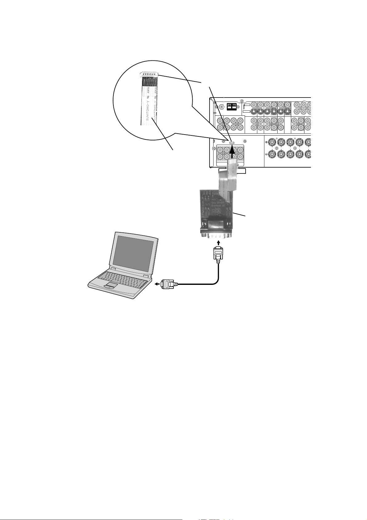
1. Use RS232C Dsub-9 pin cable (female to female/Straight type) to connect PC and the unit.
2. COM port on PC needs to be set by dialog box for each pro gram. COM port can be set from COM1 to COM5.
There are two mode of download, regarding to the target of software as bellow.
Mode 1:
Download DSP’s software to 4M Flash-ROM.
This mode is to update the software for DSP.
The target devise is 4M Flash-ROM (IC40) on CUP11995 (INPUT PWB).
SR4002/PS5072 need to be set download condition, by three front buttons.
• SR4002/PS5072 : ENTER, MUTE, T-MODE
Mode 2:
Download CPU’s software to internal Flash-ROM.
11
Page 14

This mode is to update the software for DSP.
The target devise is internal flash ROM of CPU (IC11) on CUP11995 (INPUT PWB).
Download Firmware for DSP (Mode 1)
1. Put the "DSP Update" folder into anywhere on your PC’s hard disc.
2. Connect PC and DATA UPDATE KIT with RS232C cable.
3. Connect Flat wire between DATA UPDATE KIT and the ser vice connector (CN83) on the DOWNLOADER CONNECTOR
PWB of the Unit.
4. Turn on the unit.
5. Press ENTER, MUTE and T-MODE buttons si mul ta neous ly more than 5 seconds to turn the unit into Loading Mode.
6. "LOADING MODE" will be shown on FLD.
7. Launch "UpgradeDSP.exe" on PC.
8. Set the Baud Rate to 38400 then click Start com mu ni ca tion button. If the connection is made successfully, a di a log box
saying "Success to connect" appears and "CON NECT ED" is displayed on FLD.
9. Click Send the DSP codes button on the dialog box. Progress status of downloading will be shown on PC and LOADING
is displayed on FLD.
10. If downloading is completed successfully, "COMPLETED" is displayed on FLD. And a dialog box saying "Finished the
DSP code transmitting" appears. Click OK and then click CLOSE to close the application.
11. Turn off the unit.
Download Firmware for CPU (Mode 2)
1. Put the "CPU Update" folder into anywhere on your PC’s hard disc.
2. Connect PC and DATA UPDATE KIT with RS232C cable.
3. Connect Flat wire between DATA UPDATE KIT and the ser vice connector (CN83) on the DOWNLOADER CONNECTOR
PWB of the Unit.
4. Press POWER button to turn on the unit. The unit is in the boot mode. (FLD and STANDBY LED on the front panel
disappear.)
5. Launch "H8Download.exe" on PC.
6. Click other files... button in the dialog box to specify the file (XXXX.mot) to be upload.
7. Click Connect button. If the connection with the H8 microprocessor is suc cess ful ly made, a dialogue box saying
"Success to the H8 microprocessor connection" appears. If the con nec tion fails, error message will appear.
8. Click Send button to start update.
9. If the firmware is updated successfully, a dialog box say ing "Finished the firmware program sending" appears.
10. Click CLOSE button to close the application.
11. Disconnect Mains power cord.
12. Disconnect Flat wire from the service connector (CN83) on the DOWNLOADER CONNECTOR PWB of the Unit.
13. Turn on the unit.
Firmware Version Check
To check the versions of the firmware, see "Mi cro pro ces sor (CPU), DSP Version and FLD Segment Check Mode" in
"4. SERVICE MODE" section.
12
Page 15
MICROPHONE
PWB
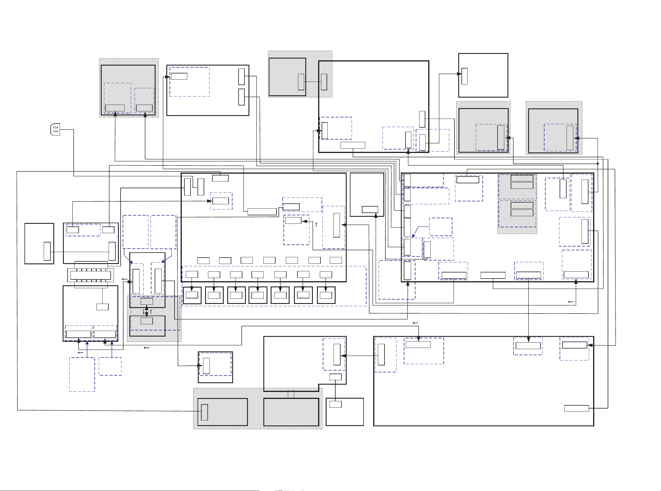
7. WIRING DIAGRAM
AC INLET
SR5002 [ /U ] Ver.
XM RADIO PWB
HDMI PWB
SR5002 Only
COMPONENT 2
PWB
VIDEO PWB
Except PS5072
TUNER MODULE
SR5002 Only
SR4002 / PS5072 Only
BRIDGE
DIODE
PWB
TRANSF.
PWB
REG. 2
PWB
SR5002 [ /U ] Ver.
MAIN PWB
IR
FLASHER
PWB
INPUT PWB
DOWNLOADER
CONNECTOR
PWB
(RC232C)
MULTI OUT PWB
BN30
CN30
MULTI SPK PWB
BN31
CN31
SR5002 Only
DOWNLOADER
CONNECTOR
PWB
FRONT
TRANSF.
PWB
POWERON/OFF
PUSH SW PWB
[ /F/L/N ] Ver. and
PS5072
BN95
CN95
REGULATOR
PWB
SELECTOR ENCODER PWB
TACT SW PWB
[/U]Ver.
13 14
TR BIAS
PWB x7
FRONT PWB
H/PPWB
Page 16
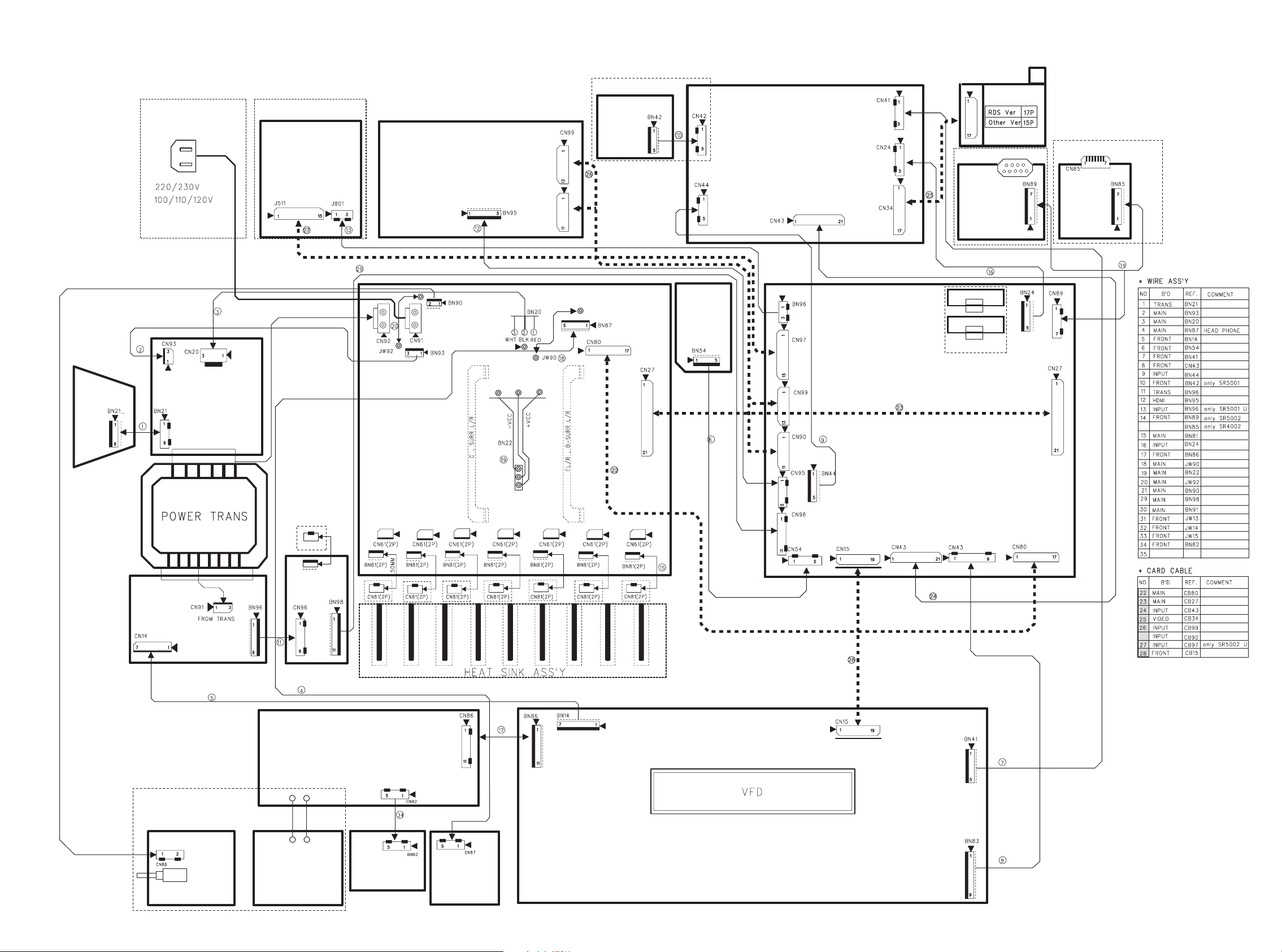
SR4002/SR5002 WIRING DIAGRAM with DC VOLTAGE
VIDEO PWB
XM RADIO PWB
HDMI PWB
AC INLET
MAIN PWB
INPUT PWB
SELECTOR
ENCODER PWB
TACT SW PWB
FRONT PWB
H/P PWB
PUSH SW PWB
COMPONENT2
PWB
TR BIAS
PWB x 7
REGULATOR
PWB
TUNER MODULE
DOWNLOADER
CONNECTOR
PWB
IR
FLASHER
PWB
FRONT
TRANSF.
PWB
MAIN TRANS
BRIDGE
DIODE
PWB
TRANSF.
PWB
MICROPHONE
PWB
SR5002/U Only
DOWNLOADER
CONNECTOR
REG. 2 PWB
PWB
7pin: +5VD
8pin: +12VA
9pin: -12VA
CN97
115
1pin: +5V
2pin: +6V
CN96
13
BN95
15
1pin: +7.5V
4pin: +5VV1(+5VD)
5pin: +5VV1(+5VD)
CN99
CN90
1
13
1
11
SR5002 Only
CN42
Except PS5072
5
1
CN42
5
1
CN41
17
1
SR5002 Only SR4002 / PS5072 Only
5
CN44
1pin: +5VL
5
4pin: +12V
5pin: +12V
1
121
CN43
CN24
4pin: +12V
5pin: +12V
1
CN45
5
17
1
1
10pin: 12V
BN89
4pin: +5VL
7
1
BN85
4pin: +5VL
7
1
1
BN21
9
CN93
13 13
1pin: -12V
CN20
BN21
13
CN91
BN96
+5VD
1pin: +5VD
2pin: 15.0V
4pin: 15.0V
6pin: 8.0V
8pin: +5VL
9pin: +5VL
91
CN14
7
1pin: -30V
6pin: +5VL
7pin: +5VD
1pin: +5VD
2pin: 15.0V
4pin: 15.0V
6pin: 8.0V
8pin: +5VL
9pin: +5VL
1
9
CN96
+5VD
1
1pin: +5VD
2pin: +5VD
5pin: -12V
8pin: +12V
10pin: +5VL
11pin: +6V
BN98
13
13
BN95
1
11
CN95
1pin: +8V
3pin: +6V
9
1
+8V +6V
SR5002/U Only
+5VL
CN92
1
1
2
2
CN91
CN63 CN61
21
BN81
21
21
CN81
CN87
CN88
1
2
12
BN90
BN93
31
1pin: -12V
BN20
WHT BLK RED
CN65
21
BN81 BN81 BN81 BN81
21 21 21 21 21
CN67 CN62
21 21 21 21
21 21 21 21
CN81 CN81 CN81 CN81
1
1pin: +5VD
5
[N/F/L]Ver. and
[/U]Ver.
PS5072
BN87
1pin: +5VD
15
117
CN80
13pin: +5VD
16pin: +5VL
17pin: +5VL
BN81
21
21
CN81
CN27
1pin: +12V
3pin: -12V
BN81
1
21
+5VD
CN66 CN64
21
21
1pin: -1.2V
CN81
2pin: +1.2V
CN86
1
11
1pin: +5VL
CN82
51
51
BN82
BN54
51
BN86
1pin: +5VL
CN98
1pin: +5VD
2pin: +5VD
5pin: -12V
8pin: +12V
10pin:+5VL
11pin:+6V
1
11
1
3
1
15
11
CN97
CN90
2pin: +6V
7pin: +5VD
8pin: +12VA
9pin: -12VA
1pin: +5V
CN96
1
CN99
13
1
CN95
6
1
11
1
+5VL
71
1pin: -30V
6pin: +5VL
7pin: +5VD
19
CN83
6pin: -12VA
8pin: +12VA
1pin: +7.5V
4pin: +5VH
5pin: +5VH
BN44
5
1pin: +5VL
4pin: +12V
1
5pin: +12V
4pin: +5VL
CN54
CN43
15 12 119
CN30
919
BN30
5pin: +12VA
6pin: -12VA
CN31
91
BN31
91
5pin: +12VA
6pin: -12VA
SR5002 Only
1
BN14
CN15
19
18pin: +5VL
CN15
119
18pin: +5VL
BN24
1
5
4pin: +12VA
5pin: +12VA
1pin: +12V
3pin: -12V
CN80
+5VD
BN43
19
6pin: -12VA
8pin: +12VA
CN89
1
7
4pin: +5VL
CN27
1
21
13pin: +5VD
16pin: +5VL
17pin: +5VL
117
BN41
51
1615
Page 17
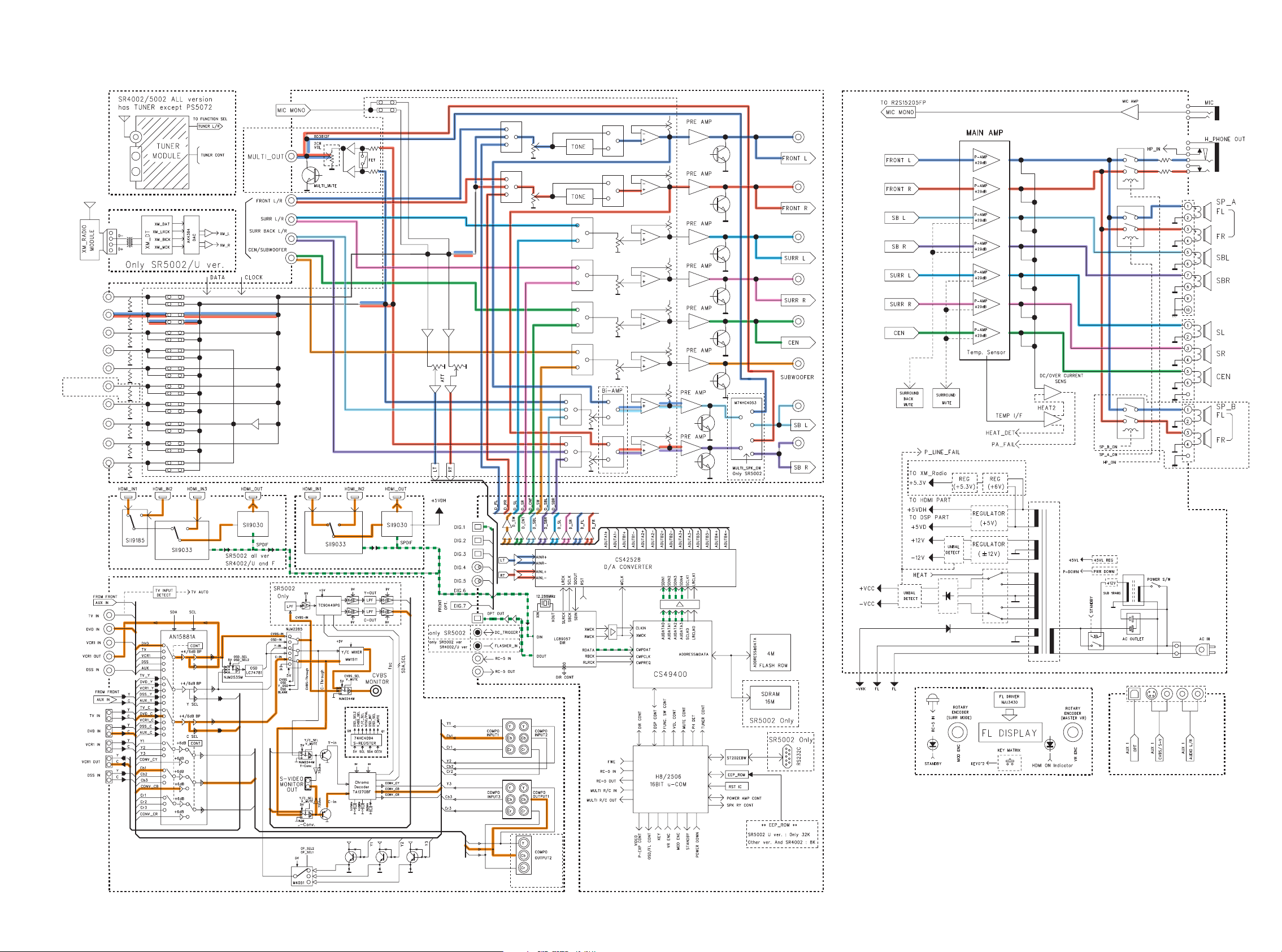
8. BLOCK DIAGRAM
PRE OUT
SR5002 Only
DVD
VCR IN
VCR OUT
DSS
TUNER
PS5072 Onl
TAPE IN
TAPE OUT
CD/CDR IN
CD/CDR OUT
7.1 CH INPUT
TV
y
(AUX 2)
R2S15205FP
SR5002/U Only
SR5002 Only
SR4002 [/L/N] ver. and PS5072
Y/C SEPARATE
R
MONITOR
MONITOR 2
SR5002 Only
1
17 18
Page 18
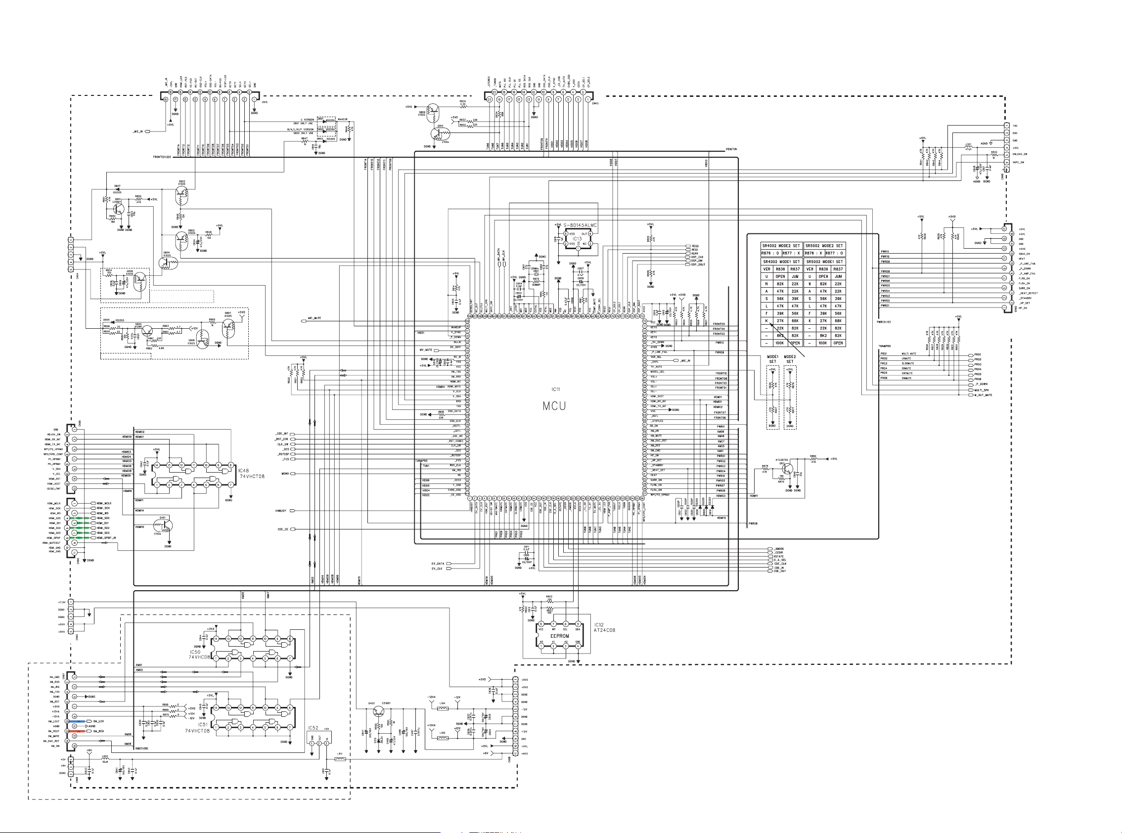
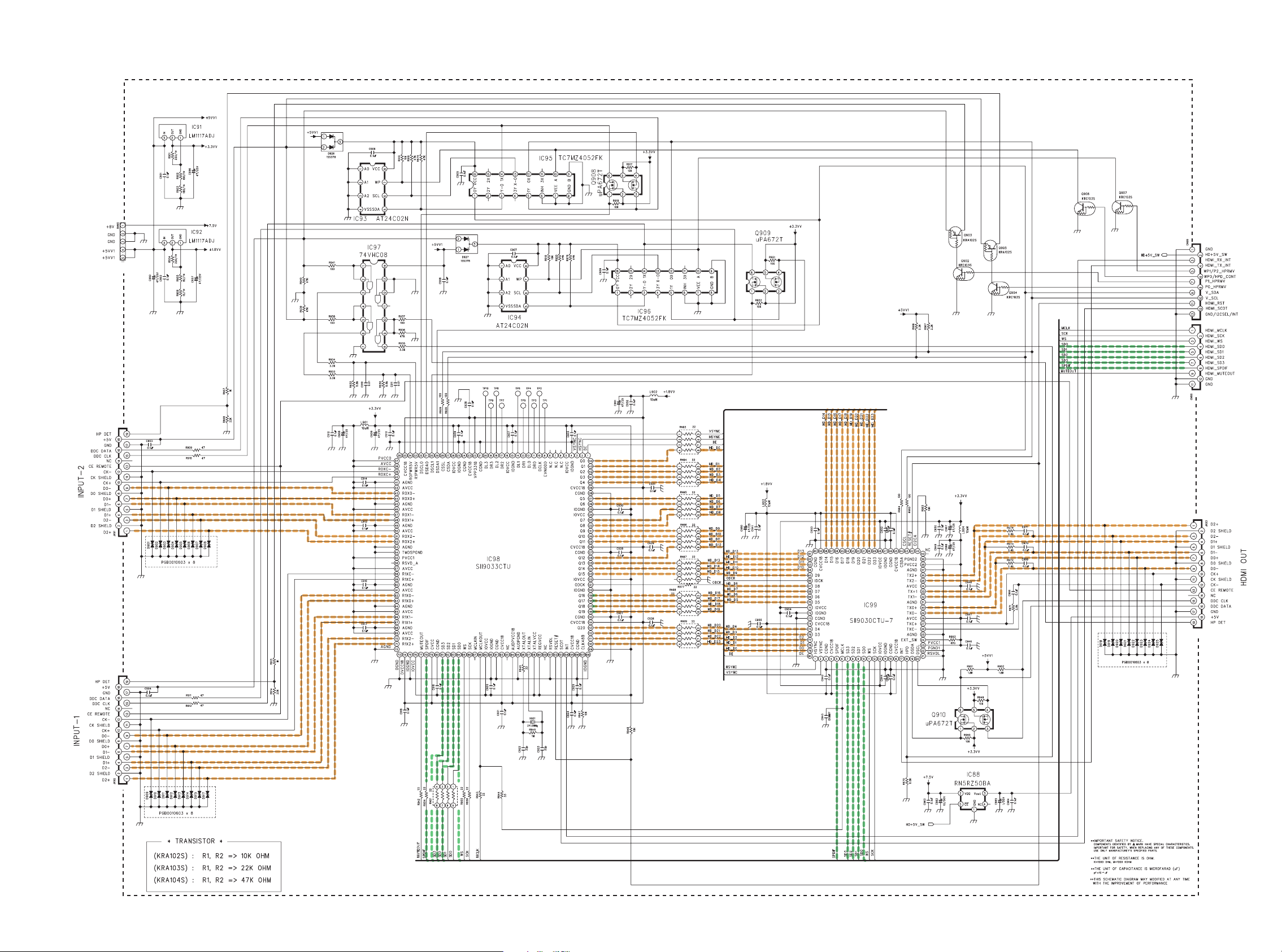
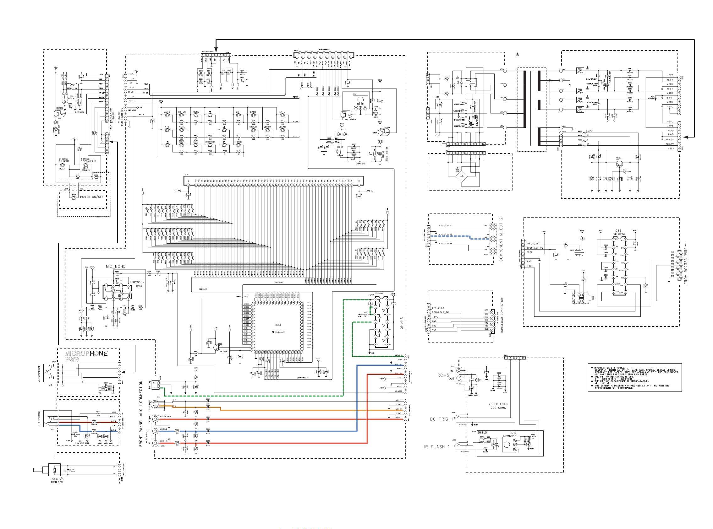
9. SCHEMATIC DIAGRAM
INPUT PWB - 1/ 3
TO FRONT PWB
TO VIDEO PWB
TO DOWN LOAD PWB
TO HDMI PWB
IR FLASHER PWB
SR5002 Only
INPUT
PWB 3 / 3
SR4002/U Only,
SR5002 Only
TO MAIN PWB
[ /K ] Ver. >> PS5072
HD64F2506
TO HDMI PWB
TO XM RADIO PWB
SR5002/U Only
TO INPUT
PWB - 2/ 3
SR5002 [ /U ] Ver. : 32K
SR4002/PS5072/SR5002 ALL : 8k
FROM REGULATOR PWB
2019
Page 19
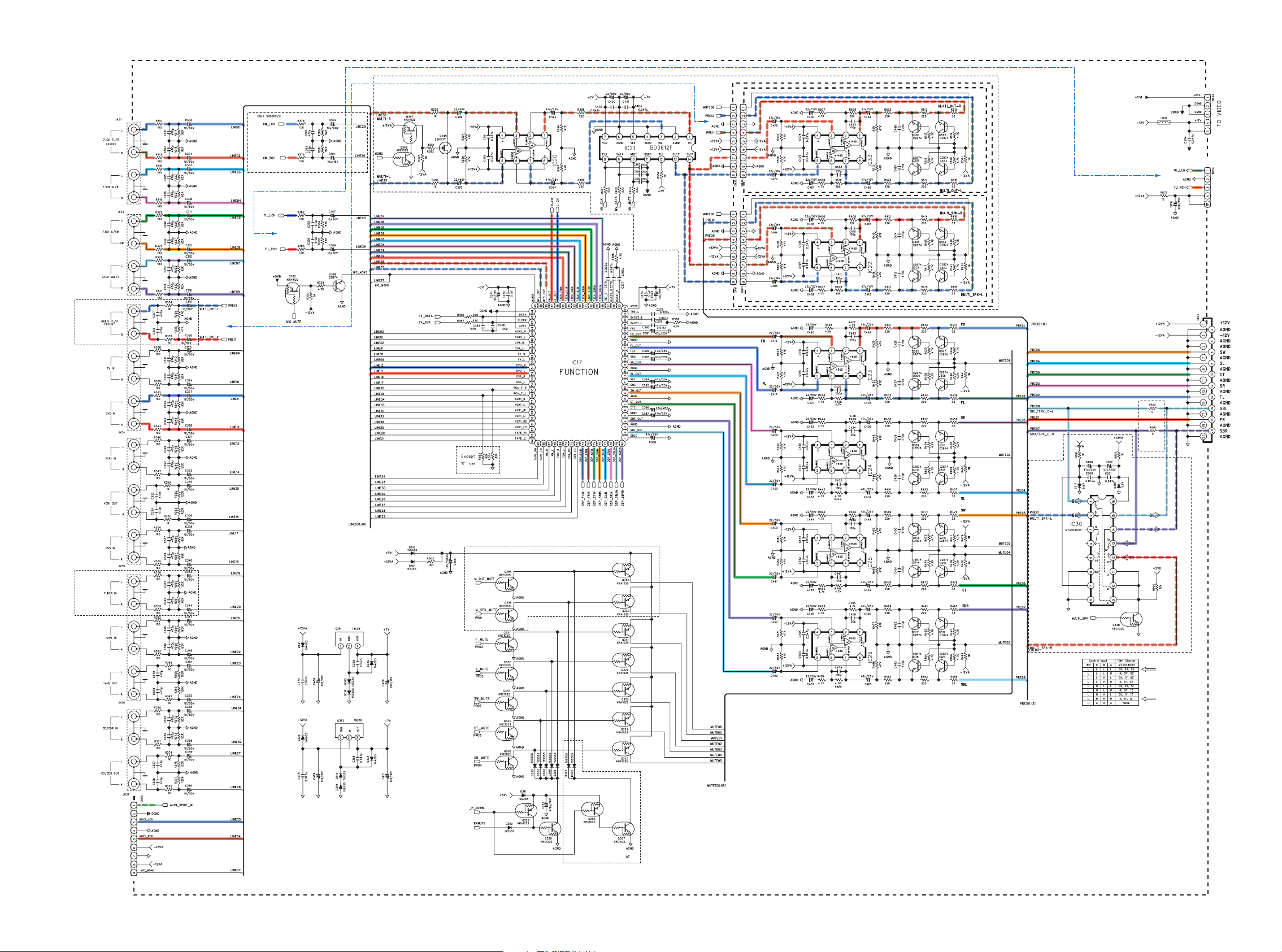
INPUT PWB - 2 / 3
SR5002 Only
MULTI PRE OUT / SPK
SR5002
Only
FROM INPUT
PWB - 1 / 3
SR5002 [ /U ] Ver.
TO INPUT
PWB - 3 / 3
PRE10 :
MULTI_SPK-L
PRE09 :
MULTI_SPK-R
MULTI OUT PWB
MULTI SPK PWB
FR
FL
SR
SL
PRE07 :
SBR /
SPK_C-R
SR4002
Only
TO VIDEO PWB
FROM VIDEO PWB
TO MAIN PWB
PS5072 [ /K ] Ver.
TO INPUT
PWB - 3 / 3
SR5002 Only
FROM INPUT
PWB - 3 / 3
SW
CT
SBR
SBL
PRE10:
SBL /
SPK_C-L
MULTI SPK B / SB SW
SR5002 Only
FROM FRONT PWB
SR5002 Only
21 22
Page 20
INPUT PWB - 3 / 3
FROM INPUT
PWB - 2 / 3
FL
FR
SL
SR
TO INPUT
PWB - 2 / 3
TO INPUT
PWB - 2 / 3
FROM INPUT
PWB - 2 / 3
FROM INPUT
PWB - 1 / 3
SR5002 Only
FROM INPUT
PWB - 1 / 3
SW
CT
SBL
SBL
TO INPUT
PWB - 2 / 3
TO INPUT
PWB - 2 / 3
SR5002 Only
2423
Page 21
SR4002/L/N ver. and PS5072 only
HDMI PWB
FROM INPUT PWB - 1 / 3
FROM INPUT PWB - 1 / 3
25 26
Page 22
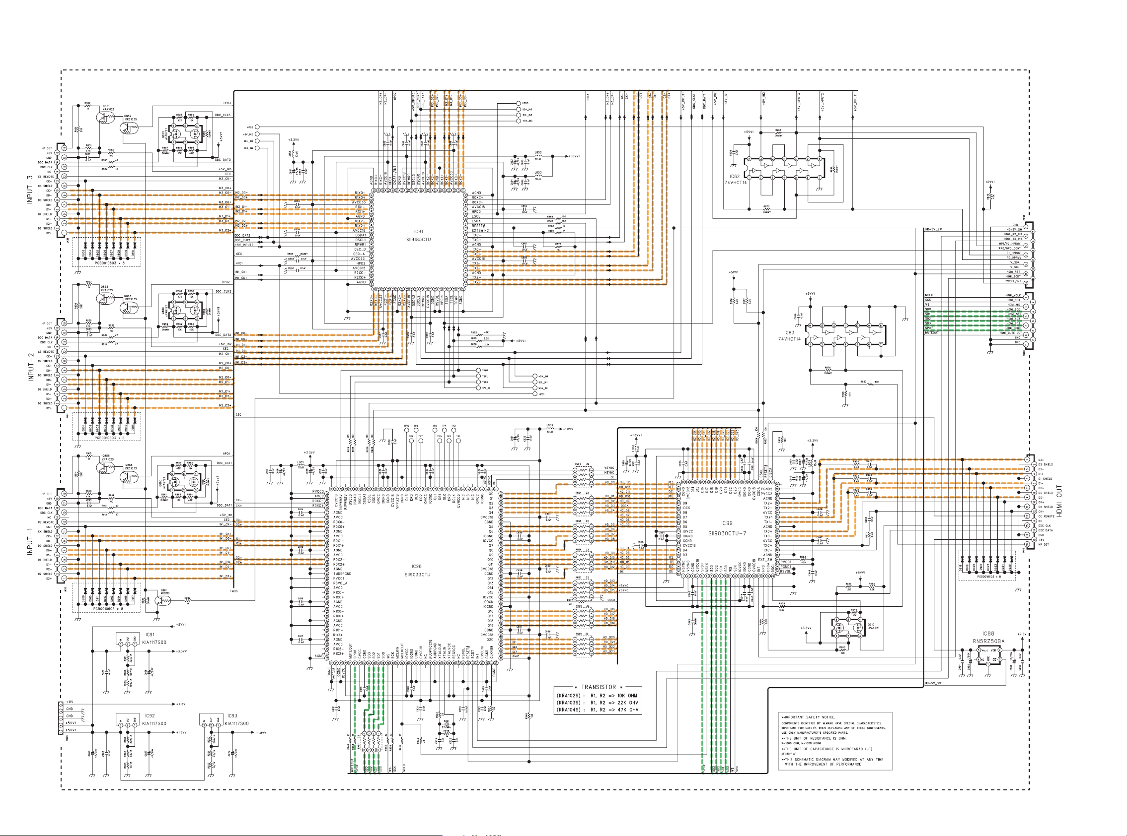
SR4002/U and SR5002 only
HDMI PWB
FROM INPUT PWB - 1 / 3
FROM INPUT PWB - 1 / 3
2827
Page 23
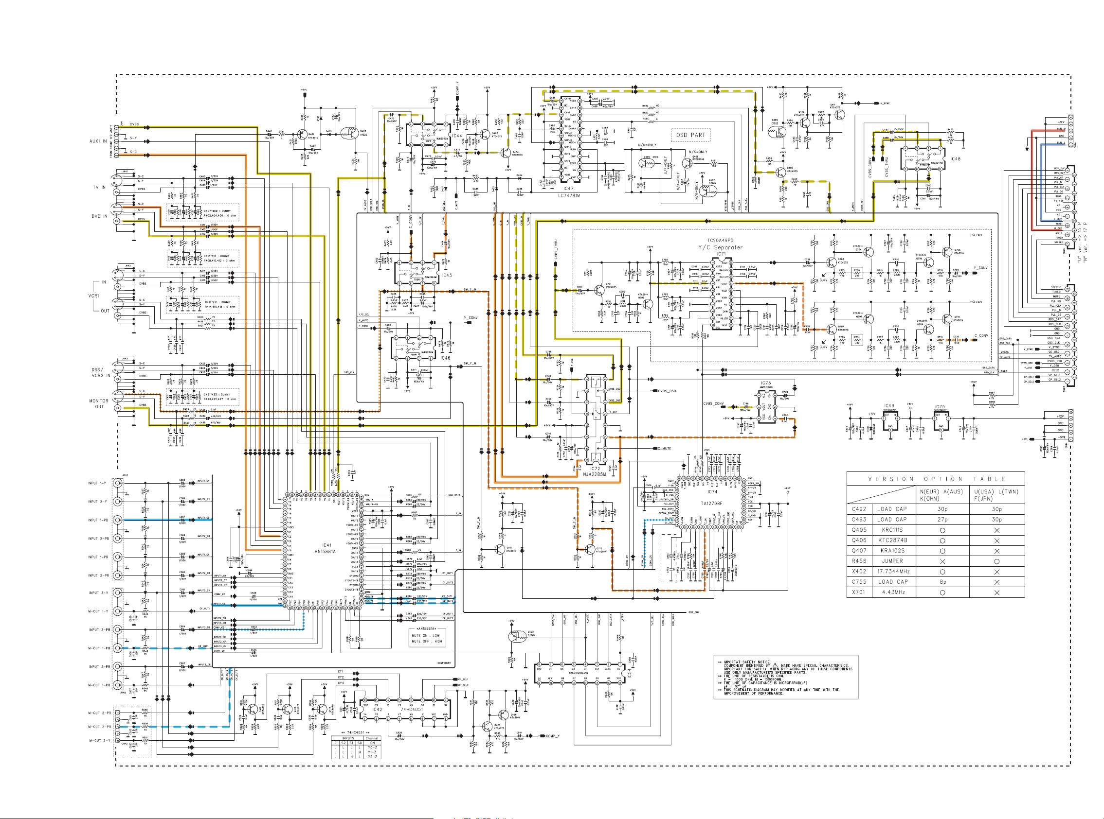
FROM FRONT PWB
VIDEO PWB
TO INPUT
PWB - 2 / 3
IC72
IC73
COMPONENT
IC48
SR5002 Only
IC45
IC45
FROM TUNER MODULE
TO INPUT PWB - 1 / 3
IC48
FROM
INPUT PWB - 2 / 3
TO COMPONENT 2 PWB
SR5002 Only
/N and PS5072 Only
29 30
Page 24
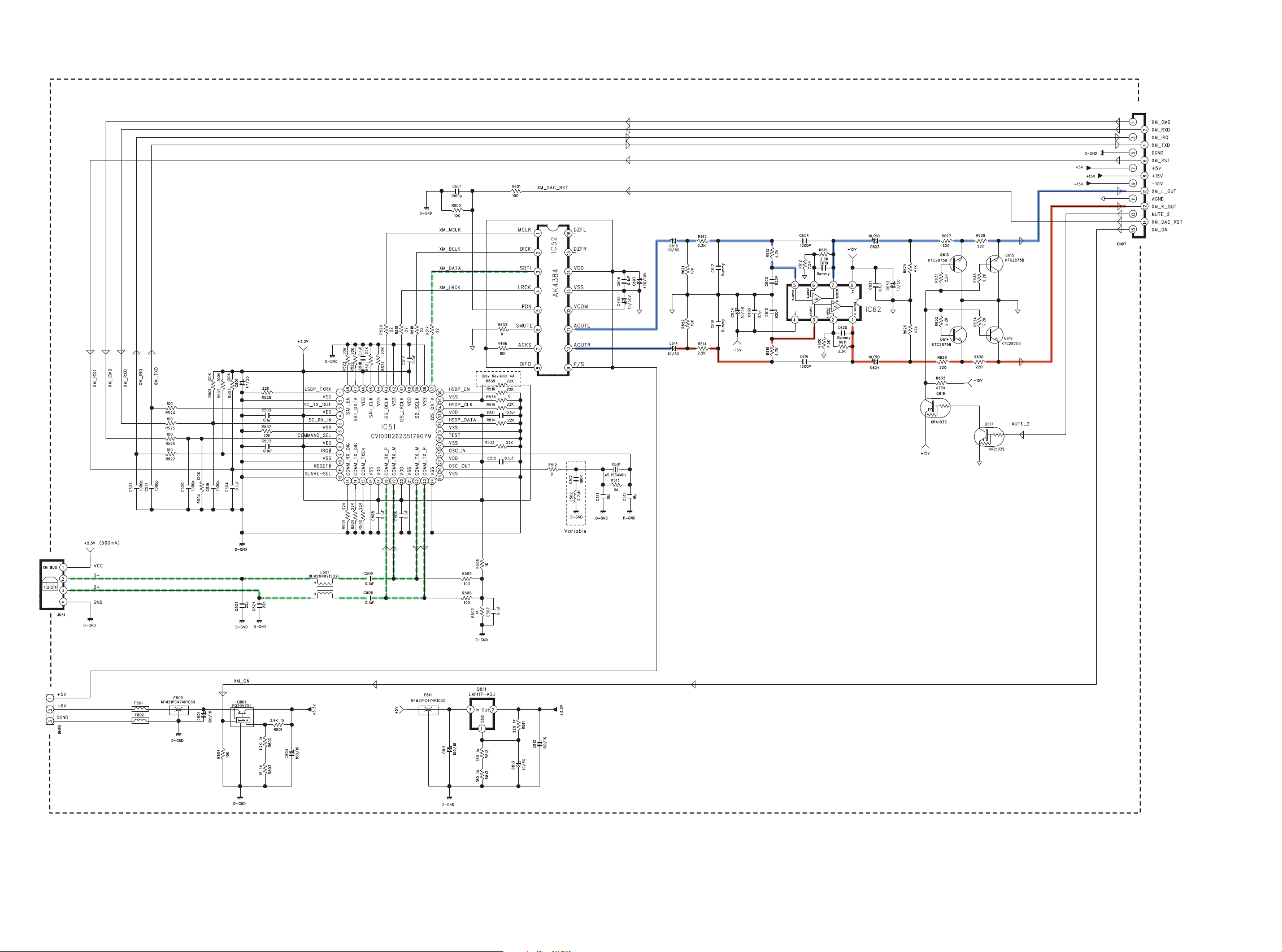
SR5002/U only
XM RADIO PWB
TO INPUT PWB - 1 / 3
FROM INPUT PWB - 1 / 3
XMDT
3231
Page 25
SELECTOR
ENCODER PWB
FRONT PWB
FROM INPUT PWB - 1 / 3
TRANSF. PWB
MAIN
TRANSF.
FRONT TRANSF. PWB
TACT SW PWB
[ /U ] Ver.
PS5072 :
BAND >> A/D,
MEMORY >> NIGHT,
CLEAR >> SLEEP,
T-MODE >> V-OFF
FROM MAIN PWB
COMPONENT 2 PWB
TO VIDEO PWB
SR5002 Only
TO REGULATOR PWB
BRIDGE
DIODE
PWB
DOWNLOADER
CONNECTOR PWB
FROM INPUT PWB - 1 / 3
MICROPHONE
PWB
H / P PWB
PUSH SW PWB
DOWNLOADER
CONNECTOR PWB
SR5002 Only
FROM INPUT PWB - 1 / 3
SR4002/PS5072 Only
FROM INPUT PWB - 1 / 3
IR
FLASHER
PWB
TO INPUT PWB - 1 / 3
SR5001 Only
TO VIDEO PWB
FROM MAIN PWB
SR4002 /U Only ,
SR5002 Only
OM MAIN PWB
33 34
Page 26
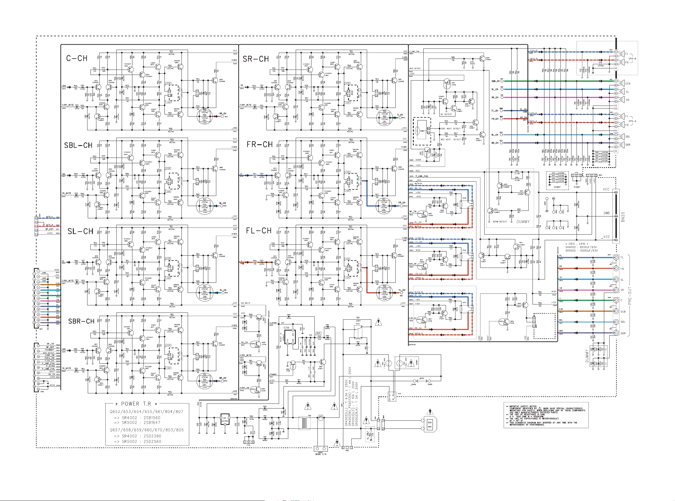
MAIN PWB
SR5001 Only
TO H / P PWB
BIAS
BIAS
T. P.
T. P.
BIAS
BIAS
T. P.
T. P.
PTC Term.
TO TRANAF. PWB
FROM POWER TRANAF. 1 PWB
SW
SL
CT
SR
FL
SBL
FR
FROM INPUT PWB - 2 / 3
SBR
FROM INPUT PWB - 1 / 3
BIAS
BIAS
T. P.
T. P.
/U Only
BIAS
T. P.
SR5002 Only
AC INLET
TO
TRANAF.
PWB
TO PUSH SW PWB
TO POWER TRANAF.
3635
Page 27
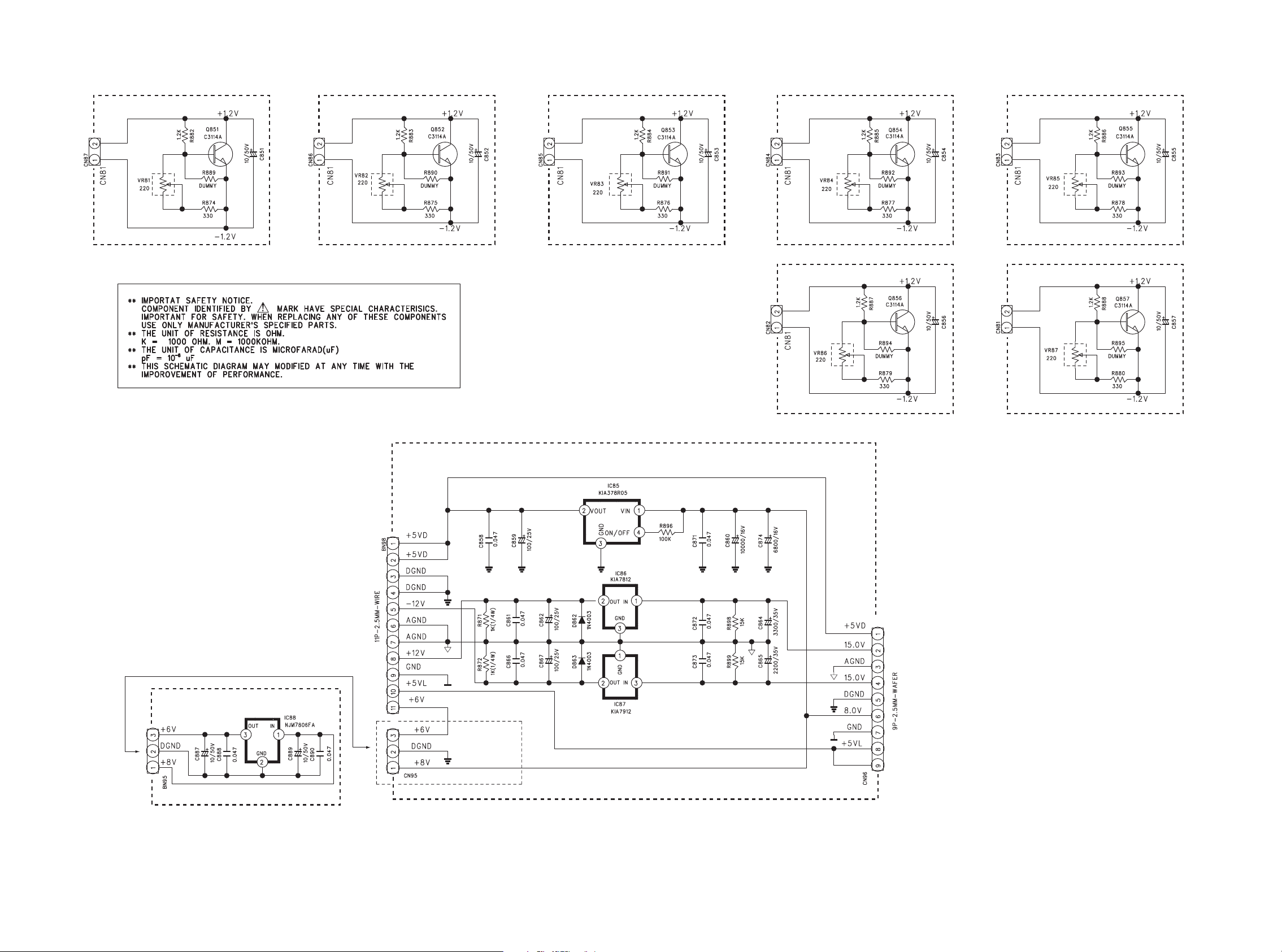
TR BIAS PWBTR BIAS PWBTR BIAS PWBTR BIAS PWBTR BIAS PWB
TO MAIN PWB
TO MAIN PWB
REGULATOR PWB
TO MAIN PWB
TO MAIN PWB
TO MAIN PWB
TO MAIN PWB
TR BIAS PWBTR BIAS PWB
TO MAIN PWB
REGULATOR 2 PWB
SR5002 /U Only
INPUT PWB - 2 / 3
TO
FROM FRONT TRANAF. PWB
SR5002 /U Only
37 38
Page 28
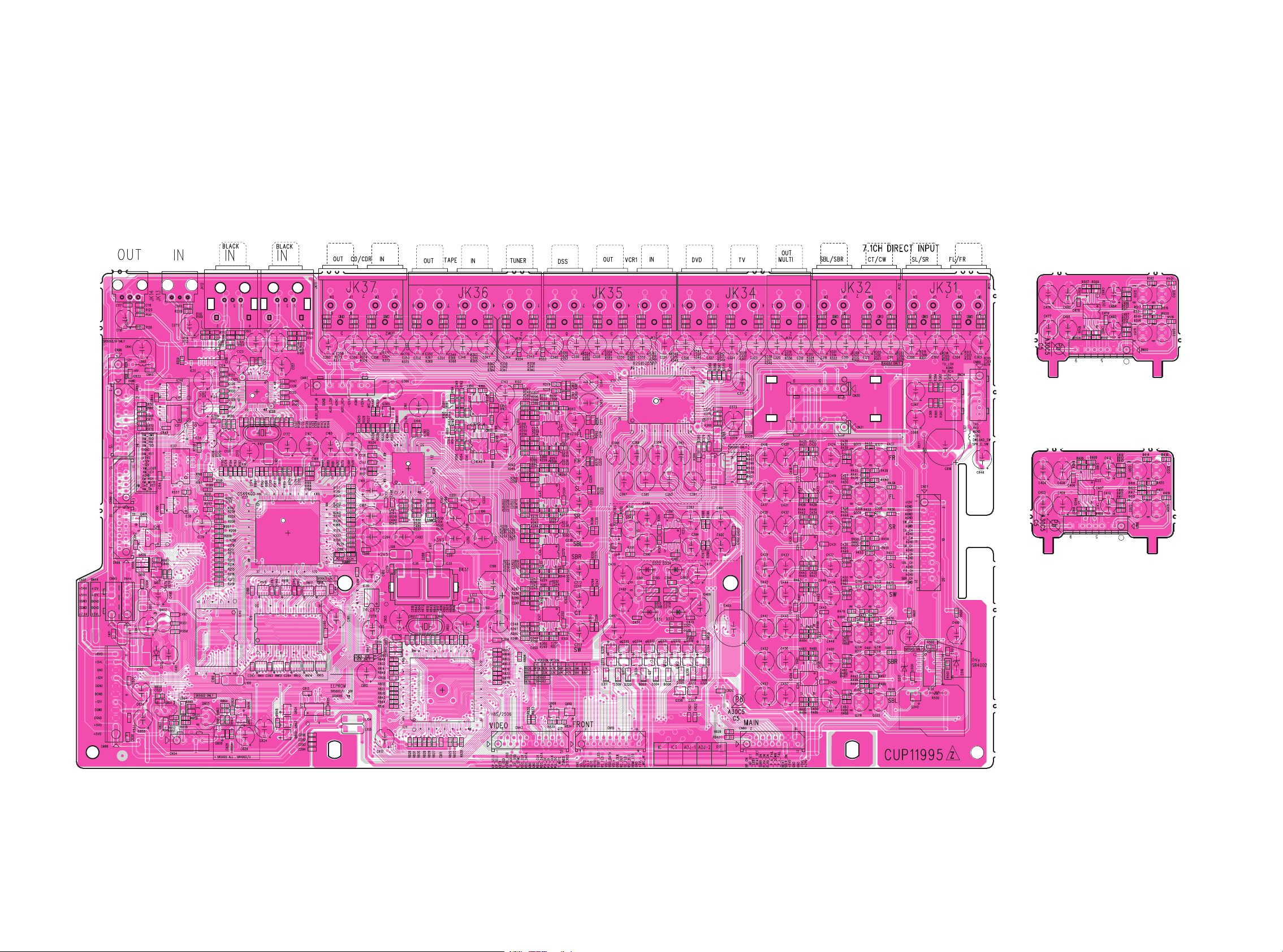
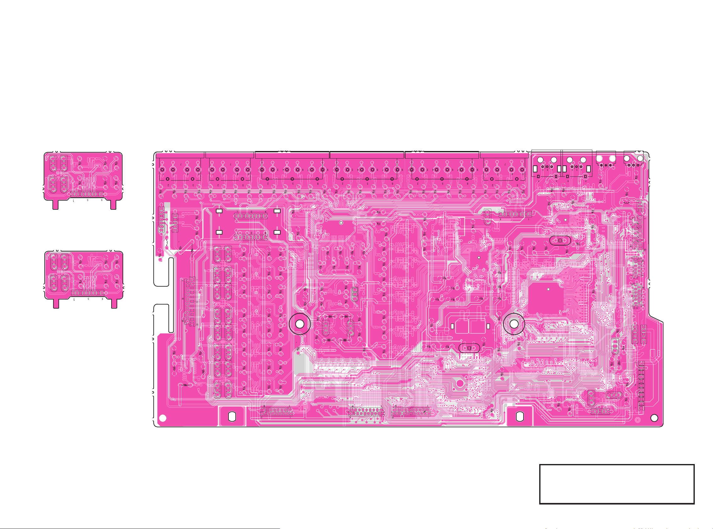
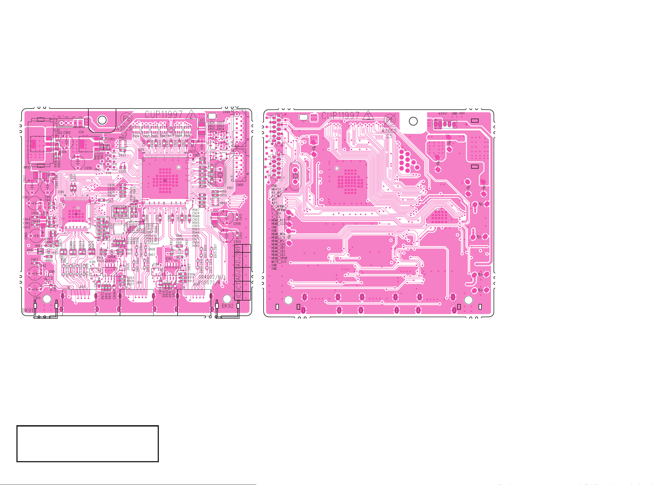
10. PARTS LOCATION
).05407"!
)#)#
1
)#
1
1
)#
1 11 )#11
)#
)#
)#)#
)#
)#
)# )#
11
)#
)# )# )#
)#
)#
)#
)#
)#
)#
)#
)#
11
)#
11)#
1 1
11111
11111
)#
)#
)#
)#
)#
11
11
11
11
11
11
11
11
)#
1
-5,4)/5407"!32/NLY
)#11
11
-5,4)30+07"!32/NLY
)#11
11
4039
Page 29
鉛フリー半田
-5,4)/5407""32/NLY
-5,4)30+07""32/NLY
).05407""
41 42
鉛フリー半田
半田付けには、鉛フリー半田
(Sn-Ag-Cu)
を使用してください。
Lead-free Solder
When soldering, use the Lead-free Solder (Sn-Ag-Cu).
Page 30
鉛フリー半田
($-)07"!3232ONLY
)#
1
)#
)#
)# )#
)#)#
1
)#
)#)#
11
1
($-)07""3232ONLY
鉛フリー半田
半田付けには、鉛フリー半田
(Sn-Ag-Cu)
を使用してください。
Lead-free Solder
When soldering, use the Lead-free Solder (Sn-Ag-Cu).
4443
Page 31

鉛フリー半田
($-)07"!32532ONLY
)# )#
1
)#
)#
)#
)#
1
11
1
11
)#
)#
)#
1
1
11
($-)07""32532ONLY
45 46
鉛フリー半田
半田付けには、鉛フリー半田
(Sn-Ag-Cu)
を使用してください。
Lead-free Solder
When soldering, use the Lead-free Solder (Sn-Ag-Cu).
Page 32

鉛フリー半田
-!).07"!
1 1
)#
1111
11 1 11
11
1 1 1 1 1 1 1 11 1 1 1 1 1
11
1111
111
1 1 1 1 1 1 1
111
11
111
11
111
1
1
1111
11
11
1 11
111
1111
1 11
1111
1
11
111
11 1
1111
11
11
1111
11
1
1
11
鉛フリー半田
半田付けには、鉛フリー半田
(Sn-Ag-Cu)
を使用してください。
Lead-free Solder
When soldering, use the
Lead-free Solder (Sn-Ag-Cu).
4847
Page 33

鉛フリー半田
-!).07""
49 50
鉛フリー半田
半田付けには、鉛フリー半田
(Sn-Ag-Cu)
を使用してください。
Lead-free Solder
When soldering, use the
Lead-free Solder (Sn-Ag-Cu).
Page 34

鉛フリー半田
42")!307"!
1111
111
42")!307""
6)$%/07"!
)#
)#
11)#1
11
11
)#
)#
)#
11
11
11
11
11
)#
)#
1
)#
)#
11
1
)#)#
)#11
)#
11
1
1
2%'07"!325ONLY
)#
2%'5,!4/207"!
)#)#)#
2%'07""325ONLY
2%'5,!4/207""
#/-0/.%.407"!32ONLY
#/-0/.%.407""32ONLY
鉛フリー半田
半田付けには、鉛フリー半田
(Sn-Ag-Cu)
を使用してください。
Lead-free Solder
When soldering, use the Lead-free Solder (Sn-Ag-Cu).
)2&,!3(%207"!
)#
)2&,!3(%207""
5251
Page 35

鉛フリー半田
6)$%/07""
8-2!$)/07"!325ONLY
)#
)#
111
)#
1
1
8-2!$)/07""325ONLY
"2)$'%$)/$%
07"!
"2)$'%$)/$%
07""
42!.3&07"!
42!.3&07""
&2/.442!.3&07"!
053(3707"!
1
053(3707""
&2/.442!.3&07""
53 54
鉛フリー半田
半田付けには、鉛フリー半田
(Sn-Ag-Cu)
を使用してください。
Lead-free Solder
When soldering, use the Lead-free Solder (Sn-Ag-Cu).
Page 36

鉛フリー半田
&2/.407"!
1 1 1
-)#2/0(/.%07"!
(007"!
(007""
-)#2/0(/.%07""
$/7.,/!$%2#/..%#4/207"!
3203ONLY
$/7.,/!$%2#/..%#4/207"!
32ONLY
$/7.,/!$%2#/..%#4/207""
3203ONLY
$/7.,/!$%2#/..%#4/207""
32ONLY
)#
鉛フリー半田
半田付けには、鉛フリー半田
(Sn-Ag-Cu)
を使用してください。
Lead-free Solder
When soldering, use the Lead-free Solder (Sn-Ag-Cu).
5655
Page 37

鉛フリー半田
&2/.407""
)#
)#
)#
3%,%#4/2%.#/$%207"!
1
4!#43707"!
3%,%#4/2%.#/$%207""
4!#43707""
鉛フリー半田
半田付けには、鉛フリー半田
(Sn-Ag-Cu)
を使用してください。
57 58
Lead-free Solder
When soldering, use the Lead-free Solder (Sn-Ag-Cu).
Page 38

11. EXPLODED VIEW AND PARTS LIST
S8
S7
x2
PUSH SW PWB
[ /L/N ] Ver. and PS5072 only
24
22
23
S4
25
S1
26
S2
SW97
H/PPWB
x2
S5
28
S3
TA CT
SW
PWB
[/U]Ver.
S6
S8
S7
BK11
SELECTOR
ENCODER
PWB
X3
x2
BK12
S1
x2
S9
x5
MICROPHONE PWB
30
31
S9
32
45
46
x9
PS5072 only
[/L/N/U]Ver.
x13
S4
22
S4
S6
S4
x4
BRIDGE
DIODE
PWB
35
FRONT
TRANSF.
PWB
REGULATOR
PWB
37
S12
T901
S11
x4
[ /L/N ] Ver. and PS5072 only
TRANSF.
PWB
HDMI PWB
43
39
38
IR
FLASHER
PWB
41
40
S5
42
[/U]Ver.
S6
x2
[/N]Ver.
[/U]Ver.
S6
x6
S6
VIDEO PWB
AC INLET
S4
x2
RC91
S4
34
33
S5
S13
INPUT PWB
21
S6
x5
20
x2
S13
S10
S14
S13
x4
x12
S14
x3
S5
x7
S5
MAIN PWB
18
S9
x4
19
TUNER MODULE
DOWNLOADER
CONNECTOR
PWB
17
S9
36
x2
TR BIAS
PWB x7
16
15
x5
S1
x14
S15
S5
S3
12
14
13
11
10
S6
9
S4
S4
8
7
6
FRONT PWB
5
4
3
2
DESCRIPTION
No.
S1
SCREW
SCREW
S2
SCREW
S3
SCREW
S4
S5
SCREW
S6
SCREW
S7
SCREW
S8
SCREW
S9
SCREW
S10
SCREW
S11
SCREW
S12
SCREW
S13
SCREW
S14
SCREW
S15
SCREW
PARTS-No.
CTB3+10JR
CTB3+6JR
CTWS3+10GR
CTB3+10JFB
CTW3+8JR
CTB3+8JFB
CTB3+6JR
CTW3+12JR
CHD1A023R
CTW3+8JR
CHD4A012R
CHD1A012R
CTS3+8JR
Q,ty
19
2
2
43
14
20
4
2
13
2
4
1
9
21
1
1
6059
Page 39

P.W.B.
(
)
(MZ)
/
p
)
/
)
/
)
/
)
/
p
)
/
p
)
/
)
/
)
/
)
/
p
(
)
/
p
)
/
)
/
)
/
)
/
p
)
/
p
)
/
)
/
)
/
)
/
p
)
/
p
)
/
)
/
)
/
)
/
p
)
/
p
)
/
)
/
)
/
)
/
p
)
/
pnsp
/
pnsp
/
pnsp
/
pnsp
/
pnsp
/
p
/
/
/
/
p
pnsp
pnsp
pnsp
)
pnsp
pnsp
/
pnsp
/
pnsp
/
pnsp
/
pnsp
/
pnsp
/
pnsp
/
pnsp
/
pnsp
/
pnsp
/
pnsp
/
pnsp
/
pnsp
/
pnsp
/
pnsp
/
pnsp
/
p
)
/
)
/
)
/
)
NAME
POS. NO.
VERS.
COLOR
1
L1G ns
N1B 00M27AW154010 00M27AW154010 KNOB MASTER KNOB (BLACK
1
N1G 00M27AW154020 00M27AW154020 KNOB MASTER KNOB (GOLD
1
N1S 00M27AW154030 00M27AW154030 KNOB MASTER KNOB (SILVER
1
U1B ns
1
L1G ns
2
N1B 00M32CW248010 00M32CW248010 PANEL FRONT AL PANEL (BLACK
2
N1G 00M32CW248110 00M32CW248110 PANEL FRONT AL PANEL (GOLD
2
N1S 00M32CW248210 00M32CW248210 PANEL FRONT AL PANEL (SILVER
2
U1B ns
2
PART NO.
FOR EUR
PART NO.
PART NAME DESCRIPTION
00M27AW154020 KNOB MASTER KNOB (GOLD
00M27AW154010 KNOB MASTER KNOB (BLACK
00M32CW248110 PANEL FRONT AL PANEL (GOLD
00M32CW248020 PANEL
FRONT AL䇭PANEL
BLACK
3 00M03CW158010 00M03CW158010 WINDOW FIP WINDOW CGU2A346X
L1G ns
4
N1B 00M32CW105020 00M32CW105020 CHASSIS FRONT MOLD CHASSIS (BLACK
4
N1G 00M32CW105120 00M32CW105120 CHASSIS FRONT MOLD CHASSIS (GOLD
4
N1S 00M32CW105220 00M32CW105220 CHASSIS FRONT MOLD CHASSIS (SILVER
4
U1B ns
4
L1G ns
5
N1B 00M07BW270020 00M07BW270020 BUTTON BUTTON L (BLACK
5
N1G 00M07BW270120 00M07BW270120 BUTTON BUTTON L (GOLD
5
N1S 00M07BW270220 00M07BW270220 BUTTON BUTTON L (SILVER
5
U1B ns
5
L1G ns
6
N1B 00M07BW270010 00M07BW270010 BUTTON CURSOR BUTTON (BLACK
6
N1G 00M07BW270110 00M07BW270110 BUTTON CURSOR BUTTON (GOLD
6
N1S 00M07BW270210 00M07BW270210 BUTTON CURSOR BUTTON (SILVER
6
U1B ns
6
00M32CW105120 CHASSIS FRONT MOLD CHASSIS (GOLD
00M32CW105020 CHASSIS FRONT MOLD CHASSIS (BLACK
00M07BW270120 BUTTON BUTTON L (GOLD
00M07BW270020 BUTTON BUTTON L (BLACK
00M07BW270110 BUTTON CURSOR BUTTON (GOLD
00M07BW270010 BUTTON CURSOR BUTTON (BLACK
7 00M03CW355010 00M03CW355010 LENS HDMI INDICATOR CGL1A245Z
L1G ns
8
N1B 00M07BW270030 00M07BW270030 BUTTON BUTTON R (BLACK
8
N1G 00M07BW270130 00M07BW270130 BUTTON BUTTON R (GOLD
8
N1S 00M07BW270230 00M07BW270230 BUTTON BUTTON R (SILVER
8
U1B ns
8
L1G ns
9
N1B ns
9
N1G ns
9
N1S ns
9
U1B ns
9
00M07BW270130 BUTTON BUTTON R (GOLD
00M07BW270030 BUTTON BUTTON R (BLACK
PWB ASSY FRONT PWB ASSY COP11994N
PWB ASSY FRONT PWB ASSY COP11994N
PWB ASSY FRONT PWB ASSY COP11994N
PWB ASSY FRONT PWB ASSY COP11994M
PWB ASSY FRONT PWB ASSY COP11994U
10 00M32CW107010 00M32CW107010 SHEET CUSHION FOOT CHG1A360
L1G ns
11
N1B 00M243W057010 00M243W057010 LEG LEG GOLD/BLACK CKL2A042H11
11
N1G 00M243W057010 00M243W057010 LEG LEG GOLD/BLACK CKL2A042H11
11
N1S 00M243W057210 00M243W057210 LEG LEG FOR SILVER CKL2A042H46
11
U1B ns
11
12 ns
13 ns
14 ns
15 ns
16 ns
L1G ns
17
N1B ns
17
N1G ns
17
N1S ns
17
U1B ns
17
L1G ns
18
N1B ns
18
N1G ns
18
N1S ns
18
U1B ns
18
L1G ns
19
N1B ns
19
N1G ns
19
N1S ns
19
U1B ns
19
L1G ns
20
N1B 90M-AV000400R 90M-AV000400R TUNER TUNER MODULE(EUR
20
N1G 90M-AV000400R 90M-AV000400R TUNER TUNER MODULE(EUR
20
N1S 90M-AV000400R 90M-AV000400R TUNER TUNER MODULE(EUR
20
00M243W057010 LEG LEG GOLD/BLACK CKL2A042H11
00M243W057010 LEG LEG GOLD/BLACK CKL2A042H11
CHASSIS CHASSIS BOTTOM CUA4A247
BUFFER CUSHION SUPPORT CHG1A305
BUFFER H=9.5(15X20
HEATSINK HEATSINK CMY2A266
BRACKET BRACKET PWB AG-D8900 CMD1A417
PWB SUPPORT PWB COP11994N-12
PWB SUPPORT PWB COP11994N-12
PWB SUPPORT PWB COP11994N-12
PWB SUPPORT PWB COP11994M-12
PWB SUPPORT PWB COP11994U-12
PWB ASSY MAIN PWB ASSY COP11999L
PWB ASSY MAIN PWB ASSY COP11999N
PWB ASSY MAIN PWB ASSY COP11999N
PWB ASSY MAIN PWB ASSY COP11999N
PWB ASSY MAIN PWB ASSY COP11999U
PWB ASSY DOWNLOAD PWB ASSY COP11994N-9
PWB ASSY DOWNLOAD PWB ASSY COP11994N-9
PWB ASSY DOWNLOAD PWB ASSY COP11994N-9
PWB ASSY DOWNLOAD PWB ASSY COP11994M-9
PWB ASSY DOWNLOAD PWB ASSY COP11994U-9
90M-AV000410R TUNER TUNER MODULE (USA
HGK1A089ZA
HGK1A089YA
HGK1A089ZA
HGK1A089XA
HGK1A089YA
CKM4A134AAC24
CKM4A134AAC23
CKM4A134AAC24
CKM4A134AAC40
CKM4A134ABC23
CGW3A382RFZD4
CGW3A382R4ZK92
CGW3A382RFZD4
CGW3A382R6ZG13
CGW3A382R4ZK92
CBT1A940RFD4
CBT1A940K92
CBT1A940RFD4
CBT1A940R6G13
CBT1A940K92
CBT1A939RFZD4
CBT1A939ZK92
CBT1A939RFZD4
CBT1A939R6ZG13
CBT1A939ZK92
CBT1A941RFD4
CBT1A941K92
CBT1A941RFD4
CBT1A941R6G13
CBT1A941K92
CHG1A104
CNVMB014MA08L
CNVMB114MA18L
CNVMB114MA18L
CNVMB114MA18L
NOTE : "nsp" PART IS LISTED FOR REFERENCE ONLY, MARANTZ WILL NOT SUPPLY THESE PARTS.
61
Page 40

P.W.B.
(
)
(MZ)
/
p
/
pnsp
/
pnsp
/
pnsp
/
pnsp
/
pnsp
pnsp
/
p
/
/
/
/
p
/
p
)
/
)
/
)
/
)
/
pnsp
/
pnsp
/
pnsp
/
pnsp
/
p
pnsp
pnsp
)
pnsp
/
pnsp
/
pnsp
/
pnsp
/
pnsp
/
pnsp
/
pnsp
/
pnsp
/
pnsp
/
pnsp
/
pnsp
pnsp
pnsp
pnsp
/
pnsp
/
pnsp
/
pnsp
/
pnsp
/
pnsp
pnsp
/
pnsp
/
pnsp
/
pnsp
/
pnsp
/
pnsp
/
pnsp
/
pnsp
/
pnsp
/
pnsp
/
pnsp
/
p
/
/
/
/
p
pnsp
p
p
p
/
p
/
p
/
p
/
p
NAME
POS. NO.
VERS.
COLOR
20
U1B ns
L1G ns
21
N1B ns
21
N1G ns
21
N1S ns
21
U1B ns
21
22 ns
L1G ns
23
N1B 00M24AW251010 00M24AW251010 BADGE NEW MZ BADGE CGB1A117
23
N1G 00M24AW251010 00M24AW251010 BADGE NEW MZ BADGE CGB1A117
23
N1S 00M24AW251020 00M24AW251020 BADGE NEW MZ BADGE SILVER CGB1A117G
23
U1B ns
23
PART NO.
FOR EUR
PART NO.
PART NAME DESCRIPTION
90M-AV000570R TUNER MODULE TUNER USA CNVMB014MA08LS
PANEL PANEL REAR SR4002/L CKF5A333Z
PANEL PANEL REAR SR4002/N CKF1A333Z
PANEL PANEL REAR SR4002/N CKF1A333Z
PANEL PANEL REAR SR4002/N CKF1A333Z
PANEL PANEL REAR SR4002/U CKF2A333Z
TAPE TAPE HEMELON CHS1A032
00M24AW251010 BADGE NEW MZ BADGE CGB1A117
00M24AW251010 BADGE NEW MZ BADGE CGB1A117
24 00M27AW355010 00M27AW355010 LENS STANDBY LENS CGL1A216
L1G ns
25
N1B 00M27AW270040 00M27AW270040 BUTTON POWER SW BUTTON (BLACK
25
N1G 00M27AW270140 00M27AW270140 BUTTON POWER SW BUTTON (GOLD
25
N1S 00M27AW270240 00M27AW270240 BUTTON POWER SW BUTTON (SILVER
25
L1G ns
26
N1B ns
26
N1G ns
26
N1S ns
26
U1B ns
28
30 ns
32 ns
33 ns
L1G ns
34
N1B ns
34
N1G ns
34
N1S ns
34
U1B ns
34
L1G ns
35
N1B ns
35
N1G ns
35
N1S ns
35
U1B ns
35
36 ns
37 ns
38 ns
L1G ns
39
N1B ns
39
N1G ns
39
N1S ns
39
U1B ns
39
40 ns
L1G ns
41
N1B ns
41
N1G ns
41
N1S ns
41
U1B ns
41
L1G ns
42
N1B ns
42
N1G ns
42
N1S ns
42
U1B ns
42
L1G ns
43
N1B 90M-ZZ004730R 90M-ZZ004730R PWB ASSY HDMI PWB ASSY COP11997B
43
N1G 90M-ZZ004730R 90M-ZZ004730R PWB ASSY HDMI PWB ASSY COP11997B
43
N1S 90M-ZZ004730R 90M-ZZ004730R PWB ASSY HDMI PWB ASSY COP11997B
43
U1B ns
43
BN91 ns
CB15 ns
CB27 ns
CB43 ns
CB45
CB45
CB45
CB45
L1G ns
N1B ns
N1G ns
N1S ns
00M27AW270140 BUTTON POWER SW BUTTON (GOLD
BRACKET POWER SW BRACKET CMD1A493
BRACKET POWER SW BRACKET CMD1A493
BRACKET POWER SW BRACKET CMD1A493
BRACKET POWER SW BRACKET CMD1A493
00M27AW270030 BUTTON POWER SW BUTTON TACT (BLACK)CBT1A877K92
HOLDER HOLDER PWB CHE170
BUFFER RUBBER H=16 (15X20
BRACKET BRACKET TRANS CMD2A487
PWB SUPPORT PWB COP11994N-13
PWB SUPPORT PWB COP11994N-13
PWB SUPPORT PWB COP11994N-13
PWB SUPPORT PWB COP11994M-13
PWB SUPPORT PWB COP11994U-13
PWB ASSY BRIDGE DIODE PWB ASSY COP11994N-7
PWB ASSY BRIDGE DIODE PWB ASSY COP11994N-7
PWB ASSY BRIDGE DIODE PWB ASSY COP11994N-7
PWB ASSY BRIDGE DIODE PWB ASSY COP11994M-7
PWB ASSY BRIDGE DIODE PWB ASSY COP11994U-7
PWB ASSY TR BIAS PWB ASSY COP12000B
PWB ASSY REGULATOR PWB ASSY COP12000B
BRACKET HEAT SINK BRACKET CMD1A587
PWB ASSY INPUT PWB ASSY COP11995L
PWB ASSY INPUT PWB ASSY COP11995N
PWB ASSY INPUT PWB ASSY COP11995N
PWB ASSY INPUT PWB ASSY COP11995N
PWB ASSY INPUT PWB ASSY COP11995U
SUPPORT PWB SUPPORT CRE1A071
PWB ASSY IR FLASHER PWB ASSY COP11994N-11
PWB ASSY IR FLASHER PWB ASSY COP11994N-11
PWB ASSY IR FLASHER PWB ASSY COP11994N-11
PWB ASSY IR FLASHER PWB ASSY COP11994M-11
PWB ASSY IR FLASHER PWB ASSY COP11994U-11
PWB ASSY VIDEO PWB ASSY COP11996U
PWB ASSY VIDEO PWB ASSY COP11996N
PWB ASSY VIDEO PWB ASSY COP11996N
PWB ASSY VIDEO PWB ASSY COP11996N
PWB ASSY VIDEO PWB ASSY COP11996U
90M-ZZ004730R PWB ASSY HDMI PWB ASSY COP11997B
90M-ZZ004740R PWB ASSY HDMI PWB ASSY COP11998B
CORD WIRE ASSY CWZSR4001BN91A
90M-YU003110R FPC 19P 220MM CWC4F4A19A220B
90M-YU003070R FPC 21P 120MM CWC4C4A21B120B
90M-YU003120R FPC 21P 100MM CWC4F4A21A100B
90M-YU002320R FPC 17P 150MM CWC4C4A17B150B
90M-YU002320R FPC 17P 150MM CWC4C4A17B150B
90M-YU002320R FPC 17P 150MM CWC4C4A17B150B
90M-YU002320R FPC 17P 150MM CWC4C4A17B150B
CBC1A146RFD4
CBC1A146K92
CBC1A146RFD4
CBC1A146R6G13
CHG1A160
NOTE : "nsp" PART IS LISTED FOR REFERENCE ONLY, MARANTZ WILL NOT SUPPLY THESE PARTS.
62
Page 41

P.W.B.
(
)
(MZ)
/
p
p
p
p
(21)
/
p
/
/
/
/
p
(
pnsp
/
p
/
/
/
/
p
/
p
/
p
/
/
/
/
p
/
p
/
p
/
p
/
p
/
p
/
p
/
p
p
p
/
p
)
/
p
)
/
p
)
/
p
)
/
p
)
p
/
p
)
/
p
)
/
p
)
/
p
)
/
p
)
NAME
POS. NO.
CB45
VERS.
COLOR
U1B ns
CB80 ns
CB90 ns
CB99 ns
RC91 00MYJ04002640 00MYJ04002640 INLET ! R-301
T901
T901
T901
T901
T901
L1G ns
N1B 90M-TS002850R 90M-TS002850R TRANSF. # POWER TRANSF. N CLT5V043ZES
N1G 90M-TS002850R 90M-TS002850R TRANSF. # POWER TRANSF. N CLT5V043ZES
N1S 90M-TS002850R 90M-TS002850R TRANSF. # POWER TRANSF. N CLT5V043ZES
U1B ns
PACKING
L1G ns
N1B 00M32CW851310 00M32CW851310 USER GUIDE USER GUDIE SR4002 N CQX1A1240Z
N1G 00M32CW851310 00M32CW851310 USER GUIDE USER GUDIE SR4002 N CQX1A1240Z
N1S 00M32CW851310 00M32CW851310 USER GUIDE USER GUDIE SR4002 N CQX1A1240Z
U1B ns
L1G ns
45
U1B ns
45
N1B 90M-ZC000320R 90M-ZC000320R MAINS CORD ! MAINS CORD 2WIRE 10A/250V CJA2B054Z
46
N1G 90M-ZC000320R 90M-ZC000320R MAINS CORD ! MAINS CORD 2WIRE 10A/250V CJA2B054Z
46
N1S 90M-ZC000320R 90M-ZC000320R MAINS CORD ! MAINS CORD 2WIRE 10A/250V CJA2B054Z
46
NOT STANDARD SPARE PART
L1G ns
N1B ns
N1G ns
N1S ns
U1B ns
N1B ns
N1G ns
N1S ns
L1G ns
31
N1B ns
31
N1G ns
31
N1S ns
31
U1B ns
31
L1G ns
N1B ns
N1G ns
N1S ns
U1B ns
PART NO.
FOR EUR
PART NO.
PART NAME DESCRIPTION
90M-YU002310R FPC 15P 150MM CWC4C4A15B150B
90M-YU003100R FPC 17P 180MM CWC4F4A17A180B
90M-YU003080R FPC 11P 80MM CWC4F4A11A080B
90M-YU003090R FPC 13P 80MM CWC4F4A13A080B
AC INLET CJJ8A006ZW
90M-TS002860R TRANSF. # POWER TRANSF. U CLT5V043ZUS
90M-TS002860R TRANSF. # POWER TRANSF. U CLT5V043ZUS
90M-FC500210R 90M-FC500210R FERRITE CORE WS SRH 9.9X20.0X5.3 CLZ9Z080Z
90M-FC500040R 90M-FC500040R FERRITE CORE FERRITE CORE
21.2X6.4X12.7) K5C T CLZ9Z028Z
90M-FC500130R 90M-FC500130R FERRITE CORE FERRITE CORE CLZ9Z071Z
90M-FC500030R 90M-FC500030R FERRITE CORE FERRITE RING 29X7.7X19 CLZ9W003Z
ns
CORD WIRE ASSY CWZSR4001BN91
00M32CW851360 USER GUIDE USER GUDIE SR4002 L CQX1A1293Z
00M32CW851250 USER GUIDE USER GUDIE SR4002 U CQX1A1241Z
00MZK04CW0010 00MZK04CW0010 UNIT KIT REMOTE CONTROLLER RC5001SR CARTSR5001M
90M-ZC000370R MAINS CORD ! MAINS CORD 10A/125V CJA2L080Z
90M-ZC000310R MAINS CORD ! MAINS CORD UL 032508/12 CJA2A070Z
90M-ZK000750R 90M-ZK000750R MICROPHONE MICROPHONE WITH FERRITE ASSY CJXSR5002MICROA
00M10BW067010 00M10BW067010 CAP COVER FOR FRONT JACK CGR1A344
00M32CW801020 PACKING CASE BOX OUT CARTON SR4002/L CPG1A765G
00M32CW801010 PACKING CASE BOX OUT CARTON SR4002 CPG1A765J
00M32CW801010 PACKING CASE BOX OUT CARTON SR4002 CPG1A765J
00M32CW801010 PACKING CASE BOX OUT CARTON SR4002 CPG1A765J
00M32CW801010 PACKING CASE BOX OUT CARTON SR4002 CPG1A765J
00M32CW805010 MASS CARTON BOX MASTER SR4002 CPG1A766T
00M32CW805010 MASS CARTON BOX MASTER SR4002 CPG1A766T
00M32CW805010 MASS CARTON BOX MASTER SR4002 CPG1A766T
ns
ns
ns
00M32CW809010 CUSHION PAD SNOW L SR4002 CPS2A671
00M32CW809020 CUSHION PAD SNOW R SR4002 CPS2A672
00M07BW257110 LID TOP COVER (GOLD
00M07BW257010 LID TOP COVER (BLACK
00M07BW257110 LID TOP COVER (GOLD
00M07BW257210 LID TOP COVER (SILVER
00M07BW257010 LID TOP COVER (BLACK
CKC1A155K118
CKC1A155K117
CKC1A155K118
CKC1A155G14
CKC1A155K117
90M-ZA000240R ANTENNA AM LOOP ANT CSA1A020Z
90M-ZA000210R ANTENNA ANT FM WIRE (PIGTAIL
90M-ZA000210R ANTENNA ANT FM WIRE (PIGTAIL
90M-ZA000210R ANTENNA ANT FM WIRE (PIGTAIL
90M-ZA000210R ANTENNA ANT FM WIRE (PIGTAIL
90M-ZA000290R ANTENNA FM 1 POL ANT(UL
CSA1A007
CSA1A007
CSA1A007
CSA1A007
CSA1A033Z
NOTE : "nsp" PART IS LISTED FOR REFERENCE ONLY, MARANTZ WILL NOT SUPPLY THESE PARTS.
63
Page 42

12. MICROPROCESSOR AND IC DATA
IC11 : HD64F2506
pin
Port Name Mode7 I/O use STBY Name
No
1 PE5 I/O I I HINBSY - - DSP Busy Signal
2 PE6 I/O O EV_DATA
3 PE7 I/O O EV_CLK
4 PD0 I/O O I HDMI_RST L H RESET for HDMI
5 PD1 I/O O I HD+5V SW H L +5V SW for HPD
6 PD2 I/O O I MULTIMUTE H H MULTI ROOM MUTE
7 PD3 I/O O I SWMUTE H H SUB W MUTE
8 PD4 I/O O I CNTMUTE H H CENTER SP MUTE
9 PD5 I/O O I SBMUTE H H SRR B MUTE
10 PD6 I/O O I SL/SRMUTE H H SL SR MUTE
11 PD7 I/O O I L/RMUTE H H FRONT L R MUTE
12 Vss I - I VSS - - GND
13 PC0 I/O O I CDE_CE L H CODEC CE
14 P1Vcc I YES I VCC - - +5V'
15 PC1 I/O O I CDE_OUT - H CODEC DATA OUT
16 PC2 I/O I I CDE_IN - H CODEC DATA IN
17 PC3 I/O O I CDE_CLK - H CODEC CLOCK
18 PC4 I/O O I D_A - L DIR or _ADC sel
19 PC5 I/O I I XSTATE - - DIR
20 PC6 I/O O I _CEDIR L L DIR CHIP ENABLE
21 PC7 I/O O I _XMODE L L DIR RESET
22 PB0 I/O O O IICCLK - L I2C for E2PROM
23 PB1 I/O I/O I/O IICDATA - L I2C for E2PROM
24 PB2 I/O I I _TU_SD L Tuned
25 PB3 I/O I I TU_ST H Stereo Tune/_MONO
26 PB4 I/O O I TU_MUTE H H Tuner MUTE
27 PB5 I/O O I _CE_TU L L Tuner Pack
28 PB6 I/O O I HDMI LED L H HDMI LED On
29 PB7 I/O I I _P_AMP_FAIL L - Power amp Dectect
30 PA0 I/O O I TUDOUT - L Tuner Pack
31 PA1 I/O O I TUCLK - L Tuner Pack
32 PA2 I/O I I TUDIN - Tuner Pack
33 PA3 I/O I I RDSDIN - Tuner Pack(RDS)
34 PA4 I/O O I P0_HPRMV H L IN0 HPD SWITCH HDMI 1 HP
35 PA5 I/O O I P1_HPRMV H L IN1 HPD SWITCH HDMI 2 HP
36 PA6 I/O I HPD_CONT / WP0
37 PA7 I/O I P2_HPRMV / WP1
38 PH7 I/O O I FLRA_ON H L SPK A SELECT
39 PH6 I/O O I FLRB_ON H L SPK B SELECT
40 PH5 I/O O I SURR_ON H L SURR/CNT SPK ON
41 PH4 I/O O I HEAT H ?L Power Amp±B_L_Sel
42 PH3 I/O I I _HEAT_DET H - Power Amp Heat sink TempDetect
43 PH2 I/O O I _STANDBY L L Standby Power
44 PH1 I/O I I _HP_DET L - HP Jack Detect
45 PH0 I/O O I HP_ON H L HEAD PHONE ON
46 PJ7 I/O O XM_CMD
47 PJ6 I/O O XM_RST
48 PJ5 I/O O
49 PJ4 I/O O XM_MUTE
50 PJ3 I/O O XM_ON
51 PJ2 I/O O I SB_ON H L
52 PJ1 I/O O O _STBY LED L H Standby LED On
53 PJ0 I/O O I _RSFL L L Front FL Driver
54 Vss I - I VSS - - GND
55 P97/AN15/DA1 I,I,O I I HDMI_TX_INT L H INT form HDMI TX
56 P96/AN14/DA0 I,I,O I I
57 P95/AN13 I,I I I HDMI_SCDT H - SCDT IN from HDMI
58 P94/AN12 I,I I I SEL- - - Front Select Encoder
59 P93/AN11 I,I I I SEL+ - - Front Select Encoder
60 P92/AN10 I,I I I VOL- - - Front Vol. Encoder
61 P91/AN9 I,I I I VOL+ - - Front Vol. Encoder
XM_DAC_
RST
HDMI_RX_
INT
Port Setting
Act. init
L H INT form HDMI RX
Note
SB Relay Control
SB ON:H SB OFF:L
64
Page 43

IC11 : HD64F2506
pin
Port Name Mode7 I/O use STBY Name
No
62 P90/AN8 I,I AD AD MODEL_SEL - - Model Select
63 P47/AN7 I,I AD AD TV_AUTO - - TV Video Detect
64 P46/AN6 I,I I I MIC_IN L H MIC IN
65 P45/AN5 I,I AD AD VER_SEL - - VERSION SELECT
66 P44/AN4 I,I AD AD P_LINE_FAIL - - Emergency Protection
67 AVss I - I AVSS - - GND
68 P43/AN3 I,I AD AD _5V_DOWN - - Detect 5V
69 P42/AN2 I,I AD AD KEY2 - - Front Key
70 P41/AN1 I,I AD AD KEY1 - - Front Key
71 P40/AN0 I,I AD AD KEY0 - - Front Key
72 Vref I YES I VCC - - +5V'
73 AVcc I YES I AVCC - - +5V'
74 P50/TxD2 I/O,O SO SO DSPOUT DSP, DIR Control Data OUT
75 P51/RxD2 I/O,I SI SI DSPIN DSP, DIR Control Data IN
76 P52/SCK2 I/O,O SC SC DSPCLK DSP, DIR Control CLOCK
77 PF0/~IRQ2 I/O,I INT I RERR H - DIR ERROR
78 PF1/BUZZ I/O,O O I CP_SEL1 NJM2584 1/3
79 PF2 I/O O I CP_SEL2 NJM2584 2/3
80 PF3/~ADTRG/~IRQ3 I/O,I,I I I REQ1 L - DSP INTER Q
81 PF4 I/O I I REQ2 L - DSP FINTR EQ
82 PF5 I/O O I V_CONV_SEL NJM2586
83 PF6 I/O O I COMP_MUTE NJM2586
84 P1Vcc I YES I VCC - - +5V'
85 PF7/ I/O,O I I2CSEL/INT
86 Vss I - I VSS - - GND
87 TEST I NO I TEST - - GND
88 VCL I - I VCL - - GND (0.47uF)
89 OSC2 I NO I NC - - open
90 OSC1 I NO I VSS - - GND
91 NMI I NO I NMI - - Fix H
92 MD2 I YES I MD2 - - Nomal:H, Bool:L
93 XTAL I YES I XTAL - - Xtal(20MHz)
94 Vss I NO I VSS - - GND
95 EXTAL I YES I EXTAL - - Xtal(20MHz)
96 Vcc I YES I VCC - - +5V'
97 MD0 I YES I MD0 - - Fix H
98 MD1 I YES I MD1 - - Fix H
99 ~STBY I NO I _STBY L H Fix H
100 ~RES I YES I _RES L - RESET
101 P20/TIOCA3 I/O,I/O O I MV_CL BD3812F MultiVol
102 P21/TIOCB3 I/O,I/O O I MV_DA BD3812F MultiVol
103 P22/TIOCC3 I/O,I/O O I MV_SEL BD3812F MultiVol
104 P23/TIOCD3 I/O,I/O I I SPKC_SW - - Speaker C Switch
105 P24/TIOCA4 I/O,I/O O I SPKC_CONT C-Relay Control
106 P25/TIOCB4 I/O,I/O O I KILLFLASH Kill Flasher OUT
107 P26/TIOCA5 I/O,I/O T_OUT O RC_OUT L RC BUS OUT
108 P27/TIOCB5 I/O,I/O I I NC
109 P17/TIOCB2/TCLKD I/O,I/O,I/O I I NC
110 P16/TIOCA2/~IRQ1 I/O,I/O,I INT INT WAKEUP
111 P15/TIOCB1/TCLKC I/O,I/O,I/O T_IN I VSYNC
112 P14/TIOCA1/~IRQ0 I/O,I/O,I INT I _P_DPWN L - Power Down Detect
113 P13/TIOCD0/TCLKB I/O,I/O,I/O O O KILLIR H L Kill to IR Input Signal
114 P12/TIOCC0/TCLKA I/O,I/O,I/O O I DC_OUT1 L H DC Triger1
115 P11/TIOCB0 I/O,I/O O I MV_MUTE BD3812F MultiVol
116 P10/TIOCA0 I/O,I/O T_IN I RC_IN
117 Vss I YES I VSS - - GND
118 P2Vcc I YES I VCC - - +5V'
119 P37/TxD4 I/O,O SO O XM_TXD XM->
120 P36/RxD4 I/O,I SI I XM_RXD <-XM
P35/SCK1/SCK4/SCL0/
121
~IRQ5
122 P34/RxD1/SDA0 I/O,I,I/O I I HDMI_MUTE H L MUTE INPUT for HDMI
123 P33/TxD1/SCL1 I/O,O,I/O SC I V_SCL - - Video Conv CLK
124 P32/SCK0/SDA1/~IRQ4 I/O,I/O,I/O,I SIO I V_SDA - - Video Conv DATA
125 P31/RxD0 I/O,I SI I RXD
I/O,I/O,I/
O,I/O,I
INT I HDMI_INT TX or RX or SCDT
Port Setting
Act. init
↑
↑
↑↓
- Standby Mode Release
- V-sync Det. & Change OSD
- IR In for RC-5
Note
UART for RS232C, Flash WR
Pull UP
RESET : H
65
Page 44

IC11 : HD64F2506
pin
Port Name Mode7 I/O use STBY Name
No
126 P30/TxD0 I/O,O SC I TXD
127 P77/TxD3 I/O,O SO O OSDDATA - -
128 P76/RxD3 I/O,I I I PULL DOWN
129 P75/TMO3/SCK3 I/O,I/O,I/O SC I OSDCLK - -
130 P74/TMO2/~MRES I/O,O O I _RSTFL L L Reset FL Driver
131 P73/TMO1 I/O,O I I _CEFL L L FL Driver Chip Select
132 P72/TMO0 I/O,O I I CDE_INT L H ADC(CODEC) OVER FLOW
133 P71/TMRI23/TMCI23 I/O,O,O O I RST_CODEC L H RESET CODEC
134 P70/TMRI01/TMCI01 I/O,O,O O I CLK_SW TC74VHC157 SEL
135 PG4 I/O O I _SCS L H DSP CHIP ENABLE
136 PG3 I/O O I _RSTDSP L L DSP
137 PG2 I/O O I _FCS L H DSP CHIP ENABLE
138 PG1/~IRQ7 I/O,I INT I RDS_CLK - - RDS Clock
139 PG0/~IRQ6 I/O,I INT I XM_IRQ - - XM_IRQ
140 PE0 I/O O I MONO H L Multi Mono(H)/Stereo(L)
141 PE1 I/O O I _CEEX L H P-Exp(Video)Sel A
142 PE2 I/O O I Y_OSD H L Y/C_OSD_IC_BYPASS
143 PE3 I/O O I CVBS_OSD H L CVBS_OSD_IC_BYPASS
144 PE4 I/O O I _CEOSD L H Video Circuit
Port Setting
Act. init
Note
UART for RS232C, Flash WR
Pull UP
FrontFL,Video(OSD),Y/C&Sepa,
4094,SAA,AK
FrontFL,Video(OSD),Y/C&Sepa,
4094,SAA,AK
66
Page 45

2
2
1
IC17 : R2S15205FP
REC
SUB
Multi
Rin
Multi
Lin
Rch Tone
Lch Tone
CLOCK DATA
DGND
DATA
CLOCK
AVEE
INR1
INL1
INR2
INL2
INR3
INL3
INR4
INL4
INR5
INL5
INR6
INL6
INR7
INL7
INR8
INL8
RA/RECR1
LA/RECL1
INR9
INL9
41
42
43
44
45
46
47
48
49
50
51
52
53
54
55
56
57
58
59
60
61
62
63
64
Out L
ADC
Out R
ADC
SWIN2
for
for
Volume
Volume
CIN2
Multi
SBLin
Multi
SBRin
Multi
Cin
Multi
SWin
Multi
SLin
Multi
SRin
SBRIN
SBLIN2
Lch
Rch
10
11
mono
10
11
1
2
Input selector
3
4
5
6
7
8
9
Input
ATT
1
2
Input selector
3
4
5
6
7
8
9
MONO
SUBL
SUBR
REC
ADCR
Input
ATT
ADCL
SUB
FRIN2
SRIN2
FLIN2
SLIN2
40 39 38 37 36 35 34 33 32 31 30 29 28 27 26 25
Bass/ Treble
0~-95dB,
-14~+14dB
-f
(2dB step)
(1dBstep)
I/F
MCU
MAIN
ATT
0/-6/-12/-18dB
SUB
Tone
Tone
Bass/ Treble
0~-95dB,
-14~+14dB
-f
(1dBstep)
(2dB step)
+16~-95dB,
-f(1dBstep)
+16~-95dB,
-f(1dBstep)
+16~-95dB,
-f(1dBstep)
+16~-95dB,
-f(1dBstep)
+16~-95dB,
-f(1dBstep)
+16~-95dB,
-f(1dBstep)
REC
TRER
+16~0dB
(1dBstep)
Tone
Bass&
Treble
Bass&
Treble
BASSR
+16~0dB
(1dBstep)
AGND
BASSR
AVCC
Volume
Volume
Volume
Volume
AVCC
24
23
TREL
22
BASSL2
21
BASSL1
FRC
20
FROUT
19
AGND
18
FLOUT
17
FLC
16
6-C
15
6-OUT (SR OUT)
14
AGND
13
5-OUT (SL OUT)
12
5-C
11
4-C
10
4-OUT (SW OUT)
9
AGND
8
3-OUT (C OUT)
7
3-C
6
2-C
5
2-OUT (SBR OUT)
4
AGND
3
1-OUT (SBL OUT)
2
1-C
1
MCU I/F
Volume
Volume
Volume
Volume
Volume
Volume
AVEE
Lout
Rout
SBLout
SBRout
Cout
SWout
SLout
SRout
AVCC
65 66 67 68 69 70 71 72 73 74 75 76 77 78 79 80
CIN1
NRB/RECR2
R10/RECR4
INLB/RECL2
R11/RECR5
NL10/RECL4
RECR3
NL11/RECL5
RECL3
FLIN1
FRIN1
SWIN1
SLIN1
SRIN1
SBLIN1
67
SBRIN1
Page 46

IC17 : R2S15205FP
PIN No.
19,17,
14,12,
9,7,
4,2
20,16,
15,11,
10,6,
5,1
3,8,
13,18
23,27
21,22,
25,26
24
35,34,
33,32,
31,30,
29,28
73,74,
75,76,
77,78,
79,80
Name
FROUT,FLOUT,
6-OUT,5-OUT,
4-OUT, 3-OUT,
2-OUT,1-OUT
FRC,FLC,
6-C,5-C,
4-C,3-C,
2-C,1-C
AGND
TREL, TRER
BASSL1,BASSL2
BASSR1,BASSR2
AVCC
FRIN2, FLIN2,
SRN2,SLIN2,
SWIN2,CIN2,
SBRIN2,SBLIN2
FLIN1, FRIN1,
CIN1,SWIN1,
SLIN1,SRIN1,
SBLIN1,SBRIN1
Function
Output pin of FL/FR/C/SW/SL/SR/SBL/SBR channel
Connects capacitor for reducing click noise of
L/R/C/SW/SL/SR/SBL/SBR channel volume
Analog ground of internal circuit
Frequency characteristic setting pin of L/R channel tone control (Treble)
Frequency characteristic setting pin of L/R channel tone control (Bass)
Positive power supply to internal circuit
Input pin of L/R/C/SW/SL/SR/SBL/SBR channel (Multi IN 1/2)
41 DGND
42 DATA
Digital ground of internal circuit
Input pin of control data
43 CLOCK Input pin of control clock
44
46,48,50,
52,54,56,
58,60,64
45,47,49,
51,53,55,
57,59,63
40
AVEE
INL1,INL2, INL3,
INL4,INL5,INL6,
INL7,INL8,INL9
INR1,INR2, INR3,
INR4,INR5,INR6,
INR7,INR8,INR9
MONO
38,39 SUBL,SUBR
36,37 ADCL, ADCR
72
RECL3
Negative power supply to internal circuit
Input pin of L/R channel (Input Selector)
Input pin of monaural (Input Selector)
Output pin for L/R channel SUB Output
Output pin for L/R channel ADC
Output pin for L/R channel REC Output
71 RECR3
61,62,
65,66,
67,68,
69,70
INRA/RECR1,INLA/RECL1,
INRB/RECR2,INLB/RECL2,
INR10/RECR4,INL10/RECL4,
INR11/RECR5,INL11/RECL5
Input pin of L/R channel (Input Selector)/
Output pin for L/R channel REC Output
68
Page 47

z
IC21 : BD3812F
IC27 : CS4900 Family
Electrical Characteristics (Unless otherwise noted, Ta=25qC, V
RL=10k:Rg=600:Master volume=0dB, Output gain=0dB)
Parameter
Cross-talk between channels
Volume control range
Maximum attenuation
Output gain control range
zzApplication circuit diagram
IN 1
AGND
IN 2
AGND
V
EE
AGND
CC
V
Symbol
THD
Vomax
CTC
GVR
Vmin
GOG
Min.
IQ
−
V
G
−2
−
3.4
Vno
−
20
Rin
−
−106
−
16
7pin
5pin
10µ
+
1
2
+
3
10µ
4
5
47µ
+
6
47µ
+
7
CC=7V, VEE=-7V, f=1kHz, VIN=1Vrms,
Typ .
Max.
Unit
6
mA
2
+2
0
0.005
0.09
Vrms
4.2
−
1.2
5
μVrms
30
40
k
−70
−100
−100
−103
−105
−118
18
20
+
−
+
−
LOGIC
Conditions
No signalCircuit current
dB
Measure : Pin13, 14Output voltage gain
%
Measure : Pin13, 14, BW=400∼30kHzTotal harmonic distortion ratio
Measure : Pin13, 14, THD=1%Maximum output voltage
Measure : Pin13, 14, Rg=0Ω, BW=ΙHF−AOutput noise voltage
Measure : Pin1, 3Input impedance
Ω
Measure : Pin13(OUT2), Rg=0Ω, BW=IHF−A,
dB
Reference : Pin14(OUT1)=1Vrms
dB
Measure : Pin13, 14, V
BW=IHF−A, Measure : Pin13, 14, V
dB
Measure : Pin13, 14, V
dB
IN
=3Vrms
IN
=0.4Vrms
14 OUT1
13 OUT2
12 SEL
11
DGND
MUTE
10
DA
9
CL
8
BD3812F
IN
=3Vrms
Pin
I/O Function Description
No.
1 I/O UHS0, GPIO18 Mode Select Bit 0, General Purpose I/O
2 I/O UHS1, GPIO19 Mode Select Bit 1, General Purpose I/O
3 INTREQ Control Port Interrupt Request
4 I FA1, FSCDIN Host Address Bit One or SPI Serial Control Data Input
5 I/O GPIO20 General Purpose I/O
6 I FA0, FSCCLK Host Parallel Address Bit Zero or Serial Control Port Clock
7 I/O FHS2,
FSCDIO,
FSCDOUT
Mode Select Bit 2 or Serial Control Port Data Input and
Output, Parallel Port Type Select
8 I/O GPIO21 General Purpose I/O
9 FDAT7 DSP AB Bidirectional Data Bus
10 VDD6 2.5V Supply Voltage
11 VSS6 2.5V Ground
12 FHS0, FWR,
FDS
13 O FHS1, FRD,
FR/W
Mode Select Bit 0 or Host Write Strobe or Host Data Strobe
Mode Select Bit 1 or Host Parallel Output Enable or Host
Parallel R/W
14 FDAT6 DSP AB Bidirectional Data Bus
15 I FCS Host Parallel Chip Select, Host Serial SPI Chip Select
16 O FINTREQ Control Port Interrupt Request
17 FDBCK Reser ved
18 FDAT5 DSP AB Bidirectional Data Bus
19 FDAT4 DSP AB Bidirectional Data Bus
20 VDD7 2.5V Supply Voltage
21 VSS7 2.5V Ground
22 FDAT3 DSP AB Bidirectional Data Bus
23 FDBDA Reser ved
24 FDAT2 DSP AB Bidirectional Data Bus
25 DBDA Debug Data
26 DBCK Debug Clock
27 FDAT1 DSP AB Bidirectional Data Bus
28 TEST Reser ved
29 FDAT0 DSP AB Bidirectional Data Bus
30 I/O NV_WE,
GPIO16
31 I/O NV_OE,
GPIO15
32 I/O NV_CS,
GPIO14
SRAM Write Enable, General Purpose I/O
SRAM Output Enable, General Purpose I/O
SRAM Chip Select, General Purpose I/O
33 SD_WE SDRAM Wr ite Enable
34 SD_DATA0,
EXTD0
35 SD_DATA1,
EXTD1
36 SD_DATA2,
EXTD2
37 SD_DATA3,
EXTD3
38 SD_DATA4,
EXTD4
SDRAM Data Bus, SRAM External Data Bus
SDRAM Data Bus, SRAM External Data Bus
SDRAM Data Bus, SRAM External Data Bus
SDRAM Data Bus, SRAM External Data Bus
SDRAM Data Bus, SRAM External Data Bus
39 SD_DQM0 SDRAM Data Mask 2
40 SD_DATA5,
EXTD5
SDRAM Data Bus, SRAM External Data Bus
41 VSSSD4 3.3V SDRAM/SRAM/EPROM Interface Ground
42 VDDSD4 3.3V SDRAM/SRAM/EPROM Interface Supply
43 SD_DATA6,
EXTD6
44 SD_DATA7,
EXTD7
SDRAM Data Bus, SRAM External Data Bus
SDRAM Data Bus, SRAM External Data Bus
45 SD_DQM1 SDRAM Data Mask 1
46 SD_DATA15,
EXTA18
47 SD_DATA14,
EXTA17
SDRAM Data Bus, SRAM External Address Bus
SDRAM Data Bus, SRAM External Address Bus
48 NC5 No Connect
49 SD_DATA13,
EXTA16
SDRAM Data Bus, SRAM External Address Bus
50 VSSSD3 3.3V SDRAM/SRAM/EPROM Interface Ground
51 VDDSD3 3.3V SDRAM/SRAM/EPROM Interface Supply
52 SD_DATA12,
EXTA15
53 SD_DATA11,
EXTA14
54 SD_DATA10,
EXTA13
55 SD_DATA9,
EXTA12
56 SD_DATA8,
EXTA11
SDRAM Data Bus, SRAM External Address Bus
SDRAM Data Bus, SRAM External Address Bus
SDRAM Data Bus, SRAM External Address Bus
SDRAM Data Bus, SRAM External Address Bus
SDRAM Data Bus, SRAM External Address Bus
57 VSSSD2 3.3V SDRAM/SRAM/EPROM Interface Ground
58 VDDSD2 3.3V SDRAM/SRAM/EPROM Interface Supply
59 O SD_CLK_OUT SDRAM Clock Output
60 SD_ADDR9,
EXTA9
SDRAM Address Bus, SRAM External Address Bus
69
Page 48

IC27 : CS4900 Family
Compressed
Audio
Interface
Digital
Audio
Interface
DSP AB
PLL Clock
Manager
61 I SD_CLK_IN SDRAM Re-timing Clock Input
62 SD_ADDR8,
EXTA8
63 SD_ADDR7,
EXTA7
64 SD_CLK_EN SDRAM Clock Enable
65 SD_ADDR6,
EXTA6
66 SD_ADDR5,
EXTA5
67 SD_ADDR4,
EXTA4
68 SD_CS SDRAM Chip Select
69 VSSSD1 3.3V SDRAM/SRAM/EPROM Interface Ground
70 VDDSD1 3.3V SDRAM/SRAM/EPROM Interface Supply
71 SD_BA,
EXTA19
72 SD_ADDR10,
EXTA10
73 SD_ADDR0,
EXTA0
74 SD_ADDR1,
EXTA1
75 SD_ADDR2,
EXTA2
76 SD_ADDR3,
EXTA3
77 SD_RAS SDRAM Row Address Strobe
78 SD_CAS SDRAM Column Address Strobe
79 I/O SDATAN3,
GPIO27
80 I/O SDATAN2,
GPIO26
81 I/O SDATAN1,
GPIO25
82 I/O SDATAN0,
GPIO24
83 NC4 No Connect
84 NC3 No Connect
85 I/O LRCLKN,
GPIO23
86 I/O SCLKN,
GPIO22
87 O LRCLK1 Audio Output Sample Rate Clock
88 NC2 No Connect
89 NC1 No Connect
90 VDD1 2.5V Supply Voltage
91 VSS1 2.5V Ground
92 I/O AUDATA7,
XMT958B,
GPIO31
93 I/O AUDATA6,
GPIO30
94 I/O AUDATA5,
GPIO29
95 I/O HDATA7,
GPIO7
96 I/O HDATA6,
GPIO6
97 I/O HDATA5,
GPIO5
98 O SCLK1 Audio Output Bit Clock
99 MCLK Audio Master Clock
100 VDD2 2.5V Supply Voltage
Frame
Shifter
Input
Buffer
RAM
SDRAM Address Bus, SRAM External Address Bus
SDRAM Address Bus, SRAM External Address Bus
SDRAM Address Bus, SRAM External Address Bus
SDRAM Address Bus, SRAM External Address Bus
SDRAM Address Bus, SRAM External Address Bus
SDRAM Bank Address Select, SRAM External Address Bus
SDRAM Address Bus, SRAM External Address Bus
SDRAM Address Bus, SRAM External Address Bus
SDRAM Address Bus, SRAM External Address Bus
SDRAM Address Bus, SRAM External Address Bus
SDRAM Address Bus, SRAM External Address Bus
PCM Audio Input Data, General Purpose I/O
PCM Audio Input Data, General Purpose I/O
PCM Audio Input Data, General Purpose I/O
PCM Audio Input Data, General Purpose I/O
PCM Audio Input Sample Rate Clock, General Purpose I/O
PCM Audio Input Bit Clock, General Purpose I/O
Digital Audio Output 7, S/PDIF Transmitter, General Purpose
I/O
Digital Audio Output 6, General Purpose I/O
Digital Audio Output 5, General Purpose I/O
DSP C Bidirectional Data Bus, General Purpose I/O
DSP C Bidirectional Data Bus, General Purpose I/O
DSP C Bidirectional Data Bus, General Purpose I/O
Programmable
Multistandard
Audio Decoder
Parallel or Serial
Host Interface
Shared Memory
SAI 0
SAI 1
SAI 3
SAI 2
DSP C
32-Bit DSP
DSP
RAM
Debug Port
Serial
Audio
Interface
DSP
ROM
101 VSS2 2.5V Ground
102 I/O AUDATA4,
103 I/O HDATA4,
104 O SCLK0 Audio Output Bit Clock
105 I/O HDATA3,
106 O AUDATA3,
107 O AUDATA2 Digital Audio Output 2
108 O LRCLK0 Audio Output Sample Rate Clock
109 O AUDATA1 Digital Audio Output 1
110 O AUDATA0 Digital Audio Output 0
111 I CMPCLK,
112 I/O HDATA2,
113 VSS3 2.5V Ground
114 VDD3 2.5V Supply Voltage
115 I/O HDATA1,
116 I/O HDATA0,
117 O CMPREQ,
118 I CMPDAT,
119 I FLRCLKN1 PCM Audio Input Sample Rate Clock
120 I/O WR, DS,
121 I/O RD, R/W,
122 PLLVSS PLL Ground Voltage
123 FILT2 Phase Locked Loop Filter
124 FILT1 Phase-Locked Loop Filter
125 PLLVDD PLL Supply Voltage
126 O CLKOUT,
127 I CLKIN, XTALI External Clock Input/Crystal Oscillator Input
128 CLKSEL DSP Clock Select
129 I/O CS, GPIO9 Host Parallel Chip Select, General Purpose I/O
130 I/O A0, GPIO13 Host Parallel Address Bit 0, General Purpose I/O
131 I FSDATAN1 PCM Audio Data Input One
132 VDD4 2.5V Supply Voltage
133 VSS4 2.5V Ground
134 I FSCLKN1,
135 SCS Host Serial SPI Chip Select
136 I SCDIN SPI Serial Control Data Input
137 VSS5 2.5V Ground
138 VDD5 2.5V Supply Voltage
139 I/O A1, GPIO12 Host Address Bit 1, General Purpose I/O
140 I/O SCDOUT,
141 I/O HINBSY,
142 SCCLK Serial Control Port Clock
143 I/O UHS2,
144 I RESET Master Reset Input
External Memory
Interface
Internal Bus
Parallel or Serial
GPIO28
GPIO4
GPIO3
XMT958A
FSCLKN2
GPIO2
GPIO1
GPIO0
FLRCLKN2
FSDATAN2
GPIO10
GPIO11
XTALO
STCCLK2
SCDIO
GPIO8
CS_OUT,
GPIO17
Interface
Digital
Audio
GPIO and I/O
Controller
Host Interface
DAO 0
DAO 1
Digital Audio Output 4, General Purpose I/O
DSP C Bidirectional Data Bus, General Purpose I/O
DSP C Bidirectional Data Bus, General Purpose I/O
Digital Audio Output 3, S/PDIF Transmitter
PCM Audio Input Bit Clock
DSP C Bidirectional Data Bus, General Purpose I/O
DSP C Bidirectional Data Bus, General Purpose I/O
DSP C Bidirectional Data Bus, General Purpose I/O
Frame Clock Data Request Out
PCM Audio Data Input Number Two
Host Write Strobe, Host Data Strobe, General Purpose I/O
Host Parallel Output Enable, Host Parallel R/W, General
Purpose I/O
Crystal Oscillator Output
PCM Audio Input Bit Clock
Serial Control Port Data Input and Output
Input Host Message Status, General Purpose I/O
Mode Select Bit 2, External Serial Memory Chip Select,
General Purpose I/O
70
Page 49

LC89057W
No. Port name I/O Description
1 RXOUT O Data Output
2 RX0 I Digital data Input (TTL)
3 RX1 I Digital data Input (Coaxial)
4 RX2 I Digital data Input (TTL)
5 RX3 I Digital data Input (TTL)
6 DGND Digital GND
7 DVDD Digital VDD
8 RX4 I Digital data Input (TTL)
9 RX5/VI I Digital data Input (TTL)
10 RX6/UI I Digital data Input (TTL)
11 DVDD Digital GND for PLL
12 DGND Digital VDD for PLL
13 LPF O Loop filter for PLL
14 AVDD Analog VDD for PLL
15 AGND Analog GND for PLL
16 RMCK O System clock Output for R (256fs, 512fs, XIN, VCO)
17 RBCK O/I Bit clock Output for R (64fs)
18 DGND Digital GND
19 DVDD Digital VDD
20 RLRCK O/I LR clock Input/Output for R
21 RDATA O Serial Audio data Input
22 SBCK O Bit clock Output for S (32fs, 64fs, 128fs)
23 SLRCK O LR clock Output for S (fs/2, fs, 2fs)
24 SDIN I Serial Audio data Input
25 DGND Digital GND
26 DVDD Digital VDD
27 XMCK O Oscillation amplifier
28 XOUT O XOUT
29 XIN I XIN or External clock Input (24.576MHz or 12.288MHz)
30 DVDD Digital VDD
31 DGND Digital GND
32 EMPHA/UO I/O Emphasis Information / U data Output / Set for chip address
33 AUDIO/VO I/O Detected non-PCM / V flag Output / Set for chip address
34 CKST I/O Clock timing Output / Switch to master or slave for demodulation
35 INT I/O Interrupt Output / Switch to Modulation or general-purpose I/O
36 RERR O Error Output (PLL lock, data error)
37 DO O IF, Read out data Output
38 DI I IF, Write data Input
39 CE I IF, Chip enable Input
40 CL I IF, Clock Input
41 XMODE I System reset Input
42 DGND Digital GND
43 DVDD Digital VDD
44 TMCK/PIO0 I/O 256fs system-clock Input for modulation / General-purpose I/O input/output
45 TBCK/PIO1 I/O 64fs bit-clock Input for modulation / General-purpose I/O input/output
46 TLRCK/PIO2 I/O Fs clock Input for modulation / General-purpose I/O input/output
47 TDATA/PIO3 I/O Serial audio data for modulation / General-purpose I/O input/output
48 TXO/PIOEN O/I Modulation data Output / General-purpose I/O enable input
RX6/UI
10
Microcontroller
I/F
CL
40CE39DI38
Selector
RX1
3
Input
RX0
2
RX2
4
RX3
5
RX4
8
RX5/VI
9
Demodulation
&
Lock detect
PLL
RDATA
21
Clock
Selector
C bit , Ubit
INT
35
EMPHA/UO32AUDIO
33
RERR
36
XIN
28
Modulation
RXOUT
1
XMODE
41
XOUT
29
TMCK/PIO0
44
TBCK/PIO1
45
TLRCK/PIO2
46
TDATA/PIO3
47
TXO/PIOEN
48
16
17
20
22
23
RMCK
RBCK
RLRCK
SBCK
SLRCK
DO
37
or
Parallel Port
1/N
LPF
13
27 34
24
SDIN
Data
Selector
XMCK CKST
/VO
21
RDATA
22
SBCK
23
SLRCK
24
SDIN
37
DO
38
DI
39
CE
RX0
40
CL
41
XMODE
42
43
DVDD
44
TXO/PIOEN
45
TMCK/PIO0
RX3
RX1
DGND
DVDD
DVDD
RX6/UI
12
17
RBCK
18
DGND
19
DVDD
20
RLRCK
46
TBCK/PIO1
47
48
DGND
14
15
16
13
LPF
1110987654321
3536 3334 3132 2930 2728 2526
LC89057W-VF4-E
LC89057W-VF4-E
DGND
RXOUT
RX2
RX4
RX5/VI
AVDD
AGND
RMCK
TLRCK/PIO2
TDATA/PIO3
DGND
DVDD
XMCK
XOUT
XIN
DVDD
DGND
EMPHA/UO
AUDIO
CKST
INT
RERR
*** *
**
/VO
IC28 : LC89057WVF4E
71
Page 50

IC29 : CS42528-CQ
114 dB, 192 kHz 8-Ch Codec with S/PDIF Receiver
Features
z Eight 24-bit D/A, two 24-bit A/D Converters
z 114 dB DAC / 114 dB ADC Dynamic Range
z -100 dB THD+N
z System Sampling Rates up to 192 kHz
z S/PDIF Receiver Compatible with EIAJ CP1201
and IEC-60958
z Recovered S/PDIF Clock or System Clock
Selection
z 8:2 S/PDIF Input MUX
z ADC High-pass Filter for DC Offset Calibration
z Expandable ADC Channels and One-line Mode
Support
z Digital Output Volume Control with Soft Ramp
z Digital +/-15dB Input Gain Adjust for ADC
z Differential Analog Architecture
z Supports logic levels between 5 V and 1.8 V.
RXP0
RXP1/GPO1
RXP2/GPO2
RXP3/GPO3
RXP4/GPO4
RXP5/GPO5
RXP6/GPO6
RXP7/GPO7
MUTEC
FILT+
REFGND
AGND
AINL+
AINL-
AINR+
AINR-
AOUTA1+
AOUTA1-
AOUTB1+
AOUTB1-
AOUTA2+
AOUTA2-
AOUTB2+
AOUTB2-
AOUTA3+
AOUTA3-
AOUTB3+
AOUTB3-
AOUTA4+
AOUTA4-
AOUTB4+
AOUTB4-
VARX AGND
TXP
Rx
GPO
MUTE
VQ
VA
Ref
ADC#1
ADC#2
r
e
t
l
i
F
g
o
l
a
n
A
Clock/Data
Recovery
Digita l F i lte r
Digita l F i lte r
LPFLT
DAC#1
DAC#2
DAC#3
DAC#4
DAC#5
DAC#6
DAC#7
DAC#8
General Description
The CS42528 codec provides two analog-to-digital and eight
digital-to-analog delta-sigma converters, as well as an integrated S/PDIF receiver, in a 64-pin LQFP package.
The CS42528 integrated S/PDIF receiver supports up to eight
inputs, clock recovery circuitry and format auto-detection. The
internal stereo ADC is capable of independent channel gain
control for single-ended or differential analog inputs. All eight
channels of DAC provide digital volume control and differential
analog outputs. The general purpose outputs may be driven
high or low, or mapped to a variety of DAC mute controls or
ADC overflow indicators.
The CS42528 is ideal for audio systems requiring wide dynamic range, negligible distortion and low noise, such as A/V
receivers, DVD receivers, digital speaker and automotive audio
systems.
ORDERING INFORMATION
CS42528-CQZ -10° to 70° C 64-pin LQFP Lead Free
CS42528-DQZ -40° to 85° C 64-pin LQFP Lead Free
CDB42528 Evaluation Board
DGND
S/PDIF
Decoder
DEM
Gain & Clip
Gain & Clip
r
e
t
l
i
F
l
a
t
i
g
i
D
DGND
C&U Bit
Data Bu ffe r
Format
Detector
ADC
Serial
Data
Internal M C L K
VD
VD
INT
Control
Port
Mult/Div
Serial
Audio
Interface
Port
CODEC
l
o
r
Serial
t
n
Port
o
C
e
m
u
l
o
V
RST
AD0/CS
AD1/CDIN
SDA/CDOUT
SCL/CCLK
VLC
OMCK
RMCK
SAI_LRCK
SAI_SCLK
SAI_SDOUT
VLS
ADCIN1
ADCIN2
CX_SDOUT
CX_LRCK
CX_SCLK
CX_SDIN1
CX_SDIN2
CX_SDIN3
CX_SDIN4
72
Page 51

T
IC29 : CS42528-CQ
2. PIN DESCRIPTIONS
CX_SDIN1
CX_SCLK
CX_LRCK
VD
DGND
VLC
SCL/CCLK
SDA/CDOUT
AD1/CDIN
AD0/CS
INT
RST
AINR-
AINR+
AINL+
AINL-
CX_SDIN2
CX_SDIN4
CX_SDIN3
64 63 62 61 60 59 5 8 57 56 55 54 53 52 51 5 0 49
1
2
3
4
5
6
7
8
9
10
11
12
13
14
15
16
17 18 19 20 21 2 2 23 24 25 26 27 28 29 30 31 32
VQ
FILT+
REFGND
OMCK
SAI_SCLK
SAI_LRCK
CS42528
VA
AOUTB4-
AOUTA4-
AOUTB4+
AOUTA4+
AGND
AOUTB3-
AOUTB3+
AOUTA3+
VLS
SAI_SDOU
RMCK
CX_SDOUT
ADCIN2
ADCIN1
DGND
AOUTA3-
VD
AOUTB2-
TXP
AOUTB2+
RXP0
AOUTA2+
48
47
46
45
44
43
42
41
40
39
38
37
36
35
34
33
RXP1/GPO1
RXP2/GPO2
RXP3/GPO3
RXP4/GPO4
RXP5/GPO5
RXP6/GPO6
RXP7/GPO7
VARX
AGND
LPFLT
MUTEC
AOUTA1-
AOUTA1+
AOUTB1+
AOUTB1-
AOUTA2-
Pin Name # Pin Description
CX_SDIN1
CX_SDIN2
CX_SDIN3
CX_SDIN4
CX_SCLK 2 CODEC Serial Clock (Input/Output) - Serial clock for the CODEC serial audio interface.
CX_LRCK 3 CODEC Left Right Clock (Input/Output) - Determines which channel, Left or Right, is currently active on
VD 451Digital Power (Input) - Positive power supply for the digital section.
1
Codec Serial Audio Data Input (Input) - Input for two’s complement serial audio data.
64
63
62
the CODEC serial audio data line.
DGND 552Digital Ground (Input) - Ground reference. Should be connected to digital ground.
VLC 6
Control Port Power (Input) - Determines the required signal level for the control port.
SCL/CCLK 7 Serial Control Port Clock (Input) - Serial clock for the serial control port. Requires an external pull-up
resistor to the logic interface voltage in I
SDA/CDOUT 8 Serial Control Data (Input/Output) - SDA is a data I/O line in I
2
C mode as shown in the Typical Connection Diagram.
2
C mode and requires an external pull-up
resistor to the logic interface voltage, as shown in the Typical Connection Diagram. CDOUT is the output
data line for the control port interface in SPI mode.
AD1/CDIN 9 Address Bit 1 (I2C)/Serial Control Data (SPI) (Input) - AD1 is a chip address pin in I
2
C mode; CDIN is
the input data line for the control port interface in SPI mode.
73
Page 52

IC29 : CS42528-CQ
AD0/CS 10
Address Bit 0 (I2C)/Control Port Chip Select (SPI) (Input) - AD0 is a chip address pin in I
2
C mode; CS
is the chip select signal in SPI mode.
INT 11 Interrupt (Output) - The CS42528 will generate an interrupt condition as per the Interrupt Mask register.
See “Interrupts” on page 40 for more details.
RST 12 Reset (Input) - The device enters a low power mode and all internal registers are reset to their default
settings when low.
AINRAINR+
AINL+
AINL-
VQ 17 Quiescent Voltage (Output) - Filter connection for internal quiescent reference voltage.
FILT+ 18 Positive Voltage Reference (Output) - Positive reference voltage for the internal sampling circuits.
REFGND 19 Reference Ground (Input) - Ground reference for the internal sampling circuits.
AOUTA1 +,-
AOUTB1 +,AOUTA2 +,AOUTB2 +,AOUTA3 +,AOUTB3 +,AOUTA4 +,AOUTB4 +,-
VA
VARX
AGND 2540Analog Ground (Input) - Ground reference. Should be connected to analog ground.
13
Differential Right Channel Analog Input (Input) - Signals are presented differentially to the delta-sigma
14
modulators via the AINR+/- pins.
15
Differential Left Channel Analog Input (Input) - Signals are presented differentially to the delta-sigma
16
modulators via the AINL+/- pins.
36,37
Differential Analog Output (Output) - The full-scale differential analog output level is specified in the
35,34
Analog Characteristics specification table.
32,33
31,30
28,29
27,26
22,23
21,20
24
Analog Power (Input) - Positive power supply for the analog section.
41
MUTEC 38 Mute Control (Output) - The Mute Control pin outputs high impedance following an initial power-on con-
dition or whenever the PDN bit is set to a ‘1’, forcing the codec into power-down mode. The signal will
remain in a high impedance state as long as the part is in power-down mode. The Mute Control pin goes
to the selected “active” state during reset, muting, or if the master clock to left/right clock frequency ratio
is incorrect. This pin is intended to be used as a control for external mute circuits to prevent the clicks
and pops that can occur in any single supply system. The use of external mute circuits are not manda-
tory but may be desired for designs requiring the absolute minimum in extraneous clicks and pops.
LPFLT 39 PLL Loop Filter (Output) - An RC network should be connected between this pin and ground.
RXP7/GPO7
RXP6/GPO6
RXP5/GPO5
RXP4/GPO4
RXP3/GPO3
RXP2/GPO2
RXP1/GPO1
RXP0 49 S/PDIF Receiver Input (Input) - Dedicated receiver input for S/PDIF encoded data.
TXP 50 S/PDIF Transmitter Output (Output) - S/PDIF encoded data output, mapped directly from one of the
42
S/PDIF Receiver Input/ General Purpose Output (Input/Output) - Receiver inputs for S/PDIF encoded
43
data. The CS42528 has an internal 8:2 multiplexer to select the active receiver port, according to the
44
Receiver Mode Control 2 register. These pins can also be configured as general purpose output pins,
45
ADC Overflow indicators or Mute Control outputs according to the RXP/General Purpose Pin Control
46
registers.
47
48
receiver inputs as indicated by the Receiver Mode Control 2 register.
VLS 53 Serial Port Interface Power (Input) - Determines the required signal level for the serial port interfaces.
SAI_SDOUT
54 Serial Audio Interface Serial Data Output (Output) - Output for two’s complement serial audio PCM
data from the S/PDIF incoming stream. This pin can also be configured to transmit the output of the inter-
nal and external ADCs.
RMCK 55 Recovered Master Clock (Output) - Recovered master clock output from the External Clock Reference
(OMCK, pin 59) or the PLL which is locked to the incoming S/PDIF stream or CX_LRCK.
CX_SDOUT 56 CODEC Serial Data Output (Output) - Output for two’s complement serial audio data from the internal
and external ADCs.
ADCIN1
ADCIN2
58
External ADC Serial Input (Input) - The CS42528 provides for up to two external stereo analog to digital
57
converter inputs to provide a maximum of six channels on one serial data output line when the CS42528
is placed in One Line mode.
OMCK 59 External Reference Clock (Input) - External clock reference that must be within the ranges specified in
the register “OMCK Frequency (OMCK Freqx)” on page 54.
SAI_LRCK 60 Serial Audio Interface Left/Right Clock (Input/Output) - Determines which channel, Left or Right, is
currently active on the serial audio data line.
SAI_SCLK 61 Serial Audio Interface Serial Clock (Input/Output) - Serial clock for the Serial Audio Interface.
74
Page 53

IC30 : M74HC4053
PIN No SYMBOL NAME AND FUNCTION
2, 1 bx, by Independent Input/Outputs
5, 3 cx, cy Independent Input/Outputs
6 INH INHIBIT Input
7V
EE
Negative Supply Voltage
11, 10, 9 A, B, C Select Inputs
12, 13 ax, ay Independent Input/Outputs
14, 15, 4 ax TO cy Common Output/input
8 GND Ground (0V)
16 V
CC
Positive Supply Voltage
TRUTH TABLE ( H C 4 053)
INPUT STATES
INHIBIT A or B or C
L L ax or bx or cx
L H ay or by or cy
H X NONE
X: DON’T CARE
IC40 : M29W400DT
CE
OE
WE
RESET
A0-A17
CONTROL
INPUT
LOGIC
ADDRESS
LATCH
AND
BUFFER
”ON” CHANNELS
PROGRAM/ERASE
HIGH VOL TAGE
X-DECODER
MX29LV400T/B
FLASH
ARRAY
Y-DECODER
Y-PASS GATE
ARRAY
SOURCE
HV
WRITE
STATE
MACHINE
(WSM)
STATE
REGISTER
COMMAND
DATA
DECODER
Q0-Q15/A-1
SENSE
AMPLIFIER
I/O BUFFER
PGM
DAT A
PROGRAM
DATA LATCH
HV
COMMAND
DATA LATCH
75
Page 54

IC41 : 57V161610ET7
Self Refresh Counter
Interval Timer
Address[0:10]
CLK
CKE
BA(A11)
CS
RAS
CAS
WE
UDQM
LDQM
Refresh
State Machine
Auto/Self Refresh
Precharge
Row Active
Column Active
Refresh
Counter
Address
Register
Burst Length
Counter
512Kx16
Bank 0
Row Decoder
Row Addr. Latch/Predecoder
Ref. Addr.[0:11]
Sense AMP & I/O gates
Overflow
Sense AMP & I/O gates
Row Addr. Latch/Predecoder
Column Decoder
Column Addr.
Latch & Counter
Column Decoder
512Kx16
Bank 1
DQ0
DQ1
DQ2
DQ3
DQ4
DQ5
DQ6
DQ7
DQ8
DQ9
DQ10
DQ11
DQ12
Data Input/Output Buffers
DQ13
DQ14
DQ15
I/O ControlTest ModeMode Register
IC42 : M74HC4051RM
PIN No SYMBOL NAME AND FUNCTION
3COM
Common Output/input
OUT/IN
6 INH INHIBIT Input
7V
EE
Negative Supply Voltage
11, 10, 9 A, B, C Select Inputs
13, 14, 15,
0 TO 7 Independent Input/Outputs
12, 1, 5, 2, 4
8 GND Ground (0V)
16 V
CC
INPUT STATES
INHIBIT C B A
Positive Supply Voltage
”ON” CHANNEL
LLLL 0
LLLH 1
LLHL 2
LLHH 3
LHLL 4
LHLH 5
LHHL 6
LHHH 7
H X X X NONE
X: DON’T CARE
76
Page 55

IC44 : NJM2535MTE1
IC45 : NJM2264MTE1
IC46 : NJM2244MTE1
IC48 : NJM2244MTE1
77
Page 56

IC47 : LC74781W
Pin No. Symbol Function Description
1V
2 Xtal
3 Xtal
4 CTRL1 Crystal oscillator input switching
1 Ground Ground connection (digital system ground)
SS
IN
Crystal oscillator connection
OUT
Used to connect the crystal oscillator and capacitor used to generate the internal
synchronization signal, or to input an external clock (2fsc or 4fsc).
Switches between external clock input mode and crystal oscillator mode.
Low = crystal oscillator mode, high = external clock mode
Outputs the blank signal (the OR of the character and border signals). (Outputs a composite
5 BLANK Blanking output sync signal when MOD0 is high.) Outputs the crystal oscillator clock during reset (when the
RST pin is low), but can be set up to not output this signal by microprocessor command.
6 OSC
7 OSC
IN
LC oscillator connection
OUT
Connections for the coil and capacitor that form the oscillator that generates the character
output dot clock.
Outputs the character signal. (Functions as the external synchronization signal discrimination
signal output pin when MOD0 is high, and outputs the state of the judgment as to whether the
8 CHARA Character output external synchronization signal is present or not. Outputs a high level when the synchronization
signal is present.) Outputs the dot clock (LC oscillator) during reset, but can be set up to not
output this signal by microprocessor command.
9 CS Enable input
10 SCLK Clock input
Serial data input enable input. Serial data input is enabled when low. A pull-up resistor is built in
(hysteresis input).
Serial data input clock input.
A pull-up resistor is built in (hysteresis input).
11 SIN Data input Serial data input. A pull-up resistor is built in (hysteresis input).
12 V
13 CV
2 Power supply Composite video signal level adjustment power supply pin (analog system power supply).
DD
Video signal output Composite video signal output
OUT
14 NC Must be either connected to ground or left open.
15 CV
16 V
Video signal input Composite video signal input
IN
1 Power supply Power supply (+5 V: digital system power supply)
DD
Video signal input for the built-in sync separator circuit (Used for either horizontal
17 SYNINSync separator circuit input synchronization signal or composite sync signal input when the built-in sync separator circuit is
not used.)
18 SEPCSync separator circuit bias voltage Built-in sync separator circuit bias voltage monitor pin
Built-in sync separator circuit composite sync signal output. (When MOD1 is high, outputs a high
19 SEP
20 SEP
Composite sync signal output level during internal synchronization and a low level during external synchronization.) (Outputs
OUT
Vertical synchronization Inputs a vertical synchronization signal created by integrating the SEP
IN
signal input integrator must be attached at the SEP
the SYN
input signal when the internal sync separator circuit is not used.)
IN
pin. This pin must be tied to VDD1 if unused.
OUT
pin output signal. An
OUT
The setting indicated by this pin takes priority in switching between the NTSC, PAL, PAL-M and
21 CTRL2 NTSC/PAL-M switching input PAL-N formats. A low level selects NTSC after a reset. The microprocessor command NTSC,
PAL, PAL-M, or PAL-N setting is valid. High = PAL-M format.
22 CTRL3 SEP
input control
IN
Controls whether or not the VSYNC signal is input to the SEP
high = VSYNC not input.
input. Low = VSYNC input,
IN
23 RST Reset input System reset input. A pull-up resistor is built in (hysteresis input).
24 V
1 Power supply (+5 V) Power supply (+5 V: digital system power supply)
DD
78
Page 57

IC51 : XMDT (SR5002/U only)
SAII_CLK
LSDP_TXRX
VSS
SC_TX_OUT
VDD
SC_RX_IN
VSS
COMMAND_SEL
VDD
IRQ#
VSS
RESET#
SLAVE_SEL
1
2
3
4
5
6
7
8
9
10
11
12
SAII_EN
SAII_DATA
484746
13
14
_DIG
RX_DIG
_
OMM_TX
C
COMM
I2S_OCLK
VDD
VSS
454443
XMDTIC
15161718192021
VSS
VDD
_RX_P
COMM
COMM_TX_EN
I2S_LRCLK
VSS
42
_M
MM_RX
CO
41
VDD
VDD
40
VSS
I2S_SCLK
VSS
38
39
222324
COMM_TX_P
COMM_TX_M
I2S_DATA
37
36
35
34
33
32
31
30
29
28
27
26
25
VSS
HSDP_EN
VSS
HSDP_CLK
VDD
HSDP_DATA
VSS
TEST
VSS
OSC_IN
VDD
OSC_OUT
VSS
TX+ / TXRX+ / RX-
TX_DIGL_OUT
RX_DIGL_IN
TX_EN~
OSC_IN
OSC_OUT
SLAVE_ SEL
TEST
Inter-IC
Sound
(I2S)
High Spd
Data Port
(HSDP)
2
2
COMM I/F
INE
Low Spd
Data Port
(LSDP)
COMM ENG
SAII
Sys Ctrlr
OSC
(CBM)
Bus I/F
I2S_OCLK (Mstr only)
I2S_LRCLK (M=o; S=i)
I2S_SCLK (M=o; S=i)
I2S_DATA (M=o; S=i)
HSDP_EN (M=o; S=i)
HSDP_CLK (M=o; S=i)
HSDP_DATA (M=o; S=i)
LSDP_TXRX (M=o; S=i)
SAII_EN (M=i; S=o)
SAII_CLK (M=o; S=i)
SAII_DATA (M=o; S=i)
SC_RX_IN
SC_TX_OUT
RESET~
ERR_IRQ~
COMMAND_SEL
RAM
XMDTIC
Pin
Pin Name Type
#
1 LSDP_TXRX
3 SC_TX_OUT
5 SC_RX_IN
7 COMMAND_SEL
9 IRQ#
11 RESET#
12 SLAVE_SEL
13 COMM_RX_DIG
S=In
M=Out
S=Out
M=Out
S=In
M=In
S=In
M=In
S=Out
M=Out
S=In
M=In
S=In
M=In
S=In
M=In
14 COMM_TX_DIG Output
15 COMM_TX_EN Output
18 COMM_RX_P
19 COMM_RX_M
S=In
M=In
S=In
M=In
22 COMM_TX_M Output
23 COMM_TX_P Output
26 OSC_OUT Output Crystal Output Crystal Output Crystal Buffer
28 OSC_IN
30 TEST
32 HSDP_DATA
34 HSDP_CLK
36 HSDP_EN
37 I2S_DATA
Pin
Pin Name Type
#
39 I2S_SCLK
41 I2S_LRCLK
43 I2S_OCLK
45 SAII_CLK
47 SAII_DATA
48 SAII_REQ
S=In
M=In
S=In
M=In
S=In
M=Out
S=In
M=Out
S=Out
M=In
S=In
M=Out
S=In
M=Out
S=In
M=Out
S=In
M=Out
S=Out
M=In
S=Out
M=In
S=In
M=Out
Pin# Pin Name Type
4, 8, 17, 20,
27, 33, 40, 46
2, 6, 10, 16,
21, 24, 25, 29,
31, 25, 38, 42,
VDD PWR +3.3V Supply Voltage +3.3V Supply Voltage
VSS GND Digital Ground Digital Ground
44
Function
in Slave Mode
Function
in Master Mode
Notes
Low Speed Data Port Output Low Speed Data Port Input LVTTL S/T
System Controller Bus (CBM)
Transmit Data Out
System Controller Bus (CBM)
Receive Data In
Command Mode Select In
(1= Command Mode,
0=Normal Mode)
Interrupt Request Out
(Active Low)
Asynchronous Reset In,
(Active Low)
M/S Mode Select In
(High = Slave Mode)
DT Comm Bus External
Transceiver Receive Data In
DT Comm Bus External
Transceiver Transmit Data
Out
DT Comm Bus External
Transceiver Direction Out
(1=Transmit, 0=Receive)
DT Comm Bus Internal
Receiver Differential Positive
In
DT Comm Bus Internal
Receiver Differential
Negative In
DT Comm Bus Internal
Transmitter Differential
Negative Out
DT Comm Bus Internal
Transmitter Differential
Positive Out
System Controller Bus (CBM)
Transmit Data Out
System Controller Bus (CBM)
Receive Data In
Command Mode Select In
(1= Command Mode,
0=Normal Mode)
Interrupt Request Out
(Active Low)
Asynchronous Reset In,
(Active Low)
M/S Mode Select In
(Low = Master Mode)
DT Comm Bus External
Transceiver Receive Data In
DT Comm Bus External
Transceiver Transmit Data
Out
DT Comm Bus External
Transceiver Direction Out
(1=Transmit, 0=Receive)
DT Comm Bus Internal
Receiver Differential PositiveInLVDS in+
DT Comm Bus Internal
Receiver Differential
Negative In
DT Comm Bus Internal
Transmitter Differential
Negative Out
DT Comm Bus Internal
Transmitter Differential
Positive Out
4mA, SLC
LVTTL S/T
LVTTL S/T
4mA Open
Drain
LVTTL S/T
LVTTL S/T
LVTTL S/T
LVTTL S/T
LVTTL S/T
LVDS in–
LVDS out–
LVDS out+
Crystal Input Crystal Input Crystal Buffer
Factory Test Mode Select
(1=Test, 0= Normal Oper.)
High Speed Data Port Data
Input
High Speed Data Port Clock
Input
High Speed Data Port Enable
Output
I2S Digital Port Data In
Function
in Slave Mode
I2S Digital Audio Port Bit
Clock In
I2S Digital Audio Port
Left/Right Clock In
I2S Digital Audio Port
Oversample Clock
(not used - connect to Gnd???)
SAII Port Clock Output SAII Port Clock Input
SAII Port Data Output SAII Port Data Input
SAII Port Request Input SAII Port Request Output
Function
in Slave Mode
Factory Test Mode Select
(1=Test, 0= Normal Oper.)
High Speed Data Port Data
Output
High Speed Data Port Clock
Output
High Speed Data Port Enable
Input
I2S Digital Audio Port Data
Out
Function
in Master Mode
I2S Digital Audio Port Bit
Clock Out
I2S Digital Audio Port
Left/Right Clock Out
I2S Digital Audio Port
Oversample Clock Out
Function
in Master Mode
LVTTL S/T
Out= 4mA, SLC
In=LVTTL S/T
Out= 4mA, SLC
In=LVTTL S/T
Out= 4mA, SLC
In=LVTTL S/T
Out= 4mA, SLC
In=LVTTL S/T
Notes
Out= 4mA, SLC
In=LVTTL S/T
Out= 4mA, SLC
In=LVTTL S/T
Out= 4mA, SLC
Out= 4mA, SLC
3.3V S/T
Out= 4mA, SLC
In=LVTTL S/T
Out= 4mA, SLC
In=LVTTL S/T
Notes
Notes: All Inputs are 3.3V LVTTL compatible; S/T = Schmitt Trigger inputs; SLC = Slew Rate Controller Output
79
Page 58

K
K
V
V
V
K
IC52 :AK4384ET (SR5002/U only)
FEATURES
Sampling Rate Rangi ng from 8kHz to 1 92kHz
128 times Oversampling (Normal Speed Mode)
64 ti m e s Oversampling (Dou ble Spe ed Mode)
32 times Oversampling (Quad Speed Mode)
24-Bit 8 times FIR Digital Fi l ter
SCF with High Toleranc e to Clock Jitter
2nd order Analog LPF
Single Ended Output Buffer
Digital de-emphasis for 32k, 44.1k and 48kHz sa mpling
Soft mute
Digital Attenuator (Linear 256 steps)
I/F format: 24-Bit MSB justified, 24/20/16-Bit LSB justified or I
2
S
Master clock: 256fs, 384fs, 512fs, 768fs or 1152fs (Normal Speed Mode)
128fs, 192fs, 256fs or 384fs (Double Speed Mode)
128fs, 192fs (Quad Speed Mode)
THD+N: -94dB
Dynamic Range: 106dB
Power supply: 4.5 to 5.5V
Very Small Package: 16pin TSSOP (6.4mm x 5.0mm)
P/S
SMUTE/CSN
ACKS/CCL
DIF0/CDTI
LRC
BIC
SDTI
μP
Interface
Audio
Data
Interface
PDN
De-emphasis
ATT
ATT
No. Pin Name I/O Function
1 MCLK I Master Clock Input Pin
An external TTL clock should be input on this pin.
2 BICK I Audi o Serial Data Clock Pin
3 SDTI I Audio Serial Data Input Pin
4 LRCK I L/R Clock Pin
5 PDN I Power-Down Mode Pin
When at “L”, the AK4384 is in the power-down mode and is held in reset.
The AK4384 should always be reset upon power-up.
SMUTE I Soft Mute Pin in parallel mode
6
“H”: Ena ble, “L”: Disa ble
CSN I Chip Select P in in serial mode
ACKS I Auto Setting Mode Pin in parallel mode
7
“L”: Manual Setting Mode, “H”: Auto Setting Mode
CCLK I Control Data Clock Pin in serial mode
DIF0 I Audi o Data In terface Forma t Pi n in pa r a ll el mode 8
CDTI I Control Data Input Pin in serial mode
9 P/S I
Parallel/Serial Select Pin (Internal pull-up pin)
“L”: Serial control mode, “H”: Parallel control mode
10 AOUTR O Rch Analog Output Pin
11 AOUTL O Lch Anal og Output Pin
12 VCOM O Common Voltag e Pin, VDD/2
Normally connected to VSS with a 0.1PF ceramic capacitor in parallel with a
10PF electrolytic cap.
13 VSS - Ground Pin
14 VDD - Power Supply Pin
15 DZFR O Rch Data Zero Input Detect Pin
16 DZFL O Lch Data Zero Input Detect Pin
Note: All input pins except pull-up pin should not be left floating.
Control
8X
Interpolator
8X
Interpolator
MCLK
Clock
Divider
'6
Modulator
'6
Modulator
SCF
LPF
SCF
LPF
DD
SS
COM
DZFL
DZFR
AOUTL
AOUTR
80
Page 59

IC71 : TC90A49PG
IC72 : NJM2285MTE1
IC73 : MM1511XNRE
81
Page 60

IC74 : TA1270BF
82
Page 61

IC81 : Sil 9185
83
Page 62

IC81 : Sil 9185
System Switching Pins
Pin Name Pin # Type Dir Description
DSDA0,
DSDA1,
DSDA2
DSCL0,
DSCL1,
DSCL2
RPWR0,
RPWR1,
RPWR2
HPD0,
HDP1,
HPD2
HPDIN 76
TSCL 78
TSDA 77
Note:
1. These signals are true open drain, and do not pull to ground when power is not applied to the device. These signals
require an external pull-up.
30,
50,
70
31,
51,
71
32,
52,
72
16,
36,
56
LVTTL,
Schmitt Trigger,
5V tolerant
LVTTL,
Schmitt Trigger,
5V tolerant
LVTTL,
5V Tolerant
LVTTL, 2mA,
5V Tolerant
LVTTL,
5V Tolerant
LVTTL,
Schmitt Trigger.
Open Drain
5V tolerant
LVTTL,
Schmitt Trigger,
5V tolerant
Input/
Output
Input DDC I
Input 5V Port detection input for respective port.
Output Hot Plug Detect Output for respective port.
Input Hot Plug Detect Input.
Output Master DDC I
Input/
Output
2
DDC I
C Data for respective port. Note 1.
2
C Clock for respective port. Note 1.
Connect to 5V signal from HDMI input connector.
Connect to HOTPLUG of HDMI input connector.
2
C Clock (Open Drain Output) to HDMI receiver.
2
I
C transactions required for HDCP operation are performed
2
over this I
C bus. Note 1.
Master DDC Data (Open drain output.) to HDMI receiver. I
transactions required for HDCP operation are performed over
2
this I
C bus. Note 1.
Configuration Pins
Pin Name Pin # Type Dir Description
I2CADDR/
TPWR
I2CSEL/INT# 35 Schmitt Trigger,
RSVDL 75 Input Reserved for use by Silicon Image and must be tied low.
79 LVTTL, 4mA,
5V Tolerant
Open Drain, 4mA,
5V Tolerant
Input/
I2C Slave Address input / Transmit Power Sense output pin.
Output
When RESET# is low, this pin is used as an input to latch the
2
I
C sub-address. The level on this pin is latched when the
RESET# pin transitions from low to high.
When RESET# is high, this pin is used as the TPWR output,
indicating that the selected Rx-port is has 5V present. When
none of the Rx ports are selected, this signal is low.
See page 15 for more information.
2
Input/
I
C Selection input / Interrupt output pin.
Output
When RESET# is low, this pin is used as an input to latch the
External Port Detection signal. The level on this pin is latched
when the RESET# pin transitions from low to high.
When this pin is high during reset, the external pins
EPSEL1/LSCL and EPSEL0/LSDA are used to select the Rxport as EPSEL[1:0].
When this pin is low during reset, the internal local I
is used to select the Rx-port.
After reset, this pin becomes the Interrupt output.
This is an open-drain output and requires an external pull-up.
See page 14 for more information.
Differential Signal Data Pins
Pin Name Pin # Type Dir Description
R0X0+ 22 TMDS Input
R0X0- 21 TMDS Input
R0X1+ 25 TMDS Input
R0X1- 24 TMDS Input
R0X2+ 28 TMDS Input
R0X2- 27 TMDS Input
R0C+ 19 TMDS Input
R0C- 18 TMDS Input
R1X0+ 42 TMDS Input
R1X0- 41 TMDS Input
R1X1+ 45 TMDS Input
R1X1- 44 TMDS Input
R1X2+ 48 TMDS Input
R1X2- 47 TMDS Input
R1C+ 39 TMDS Input
2
R1C- 38 TMDS Input
C
R2X0+ 62 TMDS Input
R2X0- 61 TMDS Input
R2X1+ 65 TMDS Input
R2X1- 64 TMDS Input
R2X2+ 68 TMDS Input
R2X2- 67 TMDS Input
R2C+ 59 TMDS Input
R2C- 58 TMDS Input
TX0+ 7 TMDS Output
TX0- 8 TMDS Output
TX1+ 4 TMDS Output
TX1- 5 TMDS Output
TX2+ 1 TMDS Output
TX2- 2 TMDS Output
TXC+ 10 TMDS Output
TXC- 11 TMDS Output
EXT_SWING 12 Analog Input Voltage Swing Adjust. A resistor tied from this pin to
2
C register
TMDS input Port 0 data pairs.
TMDS input Port 0 clock pair.
TMDS input port 1 data pairs.
TMDS input Port 1 clock pair.
TMDS input port 2 data pairs.
TMDS input Port 2 clock pair.
TMDS output data pairs.
TMDS output clock pair.
AVCC18 determines the amplitude of the voltage swing.
The recommended value is 500ȍ
.
Control Pins
Pin Name Pin # Type Dir Description
RESET# 13 LVTTL,
LSCL/EPSEL1 15 Schmitt
LSDA/EPSEL0 14 LVTTL,
Schmitt Trigger.
5V tolerant
5V tolerant
Schmitt Trigger.
Open Drain
5V tolerant
Input Reset Pin (Active LOW). Certain configuration inputs are
latched when RESET# transitions from low to high. See page
14 for more information.
Input Local I
Input/
Output
2
C Clock / External Port Select 1. When I2CSEL is high,
this becomes the Local I
is low, this becomes the external port select pin, EPSEL1. True
open drain, so does not pull to ground if power not applied. An
external pull-up is required.
See page 14 for more information.
2
Local I
C Data / External Port Select 0. When I2CSEL is high,
this becomes the Local I
is low, this becomes the external port select pin, EPSEL0. True
open drain, so does not pull to ground if power not applied. An
external pull-up is required.
See page 14 for more information.
2
C bus clock pin, LSCL. When I2CSEL
2
C bus data pin, LSDA. When I2CSEL
CEC Pins
Pin Name Pin # Type Direction Description
CEC_A 54 CEC Compliant,
CEC_D 53 LVTTL,
5V tolerant.
Schmitt Trigger
5V tolerant.
Input/
HDMI compliant CEC I/O used to interface to CEC devices.
Output
CEC electrically compliant signal. This pin connects to the CEC
signal of all HDMI connectors in the system.
As an input, the pad acts as a LVTTL Schmitt triggered input
and is 5V tolerant. As an output, the pad acts as an NMOS
driver with resistive pull-up. This pin has an internal pull-up
resistor.
Input/
CEC interface to local system. True open-drain. An external
Output
pull-up is required. This pin typi
cally connects to the local CPU.
Power and Ground Pins
Pin Name Pin # Type Description
AVCC33 23, 43, 55, 63 Power Analog VCC. Connect to 3.3V supply.
AVCC18 6, 17, 29, 37, 49, 57, 69 Power
AGND 3, 9, 20, 26, 40,
DVCC18 33, 73 Power Digital VCC. Connect to 1.8V supply.
DGND 34, 74 Ground Digital GND.
46, 60, 66, 80
Analog VCC. Connect to 1.8V supply.
Ground Analog GND.
84
Page 63

IC81 : NJU3430F
RST
SI
CS
CLK
RS
OSC1
OSC
2
VDD
V
V
SS
FDP
RESET
8bits
Shift
Reg.
Timing
CR
Gen.
OSC.
Instruction
Dec oder
Display
State
Reg.
Control
Line
Address
Address
Read
Address
Counter
Selector
Counter
MK RAM
16x2bit
CG RAM
35x8bit
CG ROM
8,400bit
DD RAM
16x8bit
No. SYMBOL I/O F U N C T I O N
Icon
Segment
Port
Timing
Driver
Driver
Driver
Driver
MK1~MK2
S
1~S35
P 1
T
1~T16
57 VDD - Power Source : VDD=+3.0 to 5.5V
49 VSS - GND : VSS=0V
48 VFDP -
50 OSC1 I
51 OSC2 O
VFD Driving Power Sourse
V
DD-20V to V DD-45V
CR Oscillation Terminal
External R and C connect to these terminals.
(Target f
OSC=360kHz)
Serial Clock Input Terminal
54 CLK I
The serial data input synchronizing the rise edge of this
terminal.
Chip Select Terminal
53 CS I
When the CS terminal is "H" the serial data input is not
available.
55 SI I
Serial Data Input Terminal
The data input is MSB first.
Register Selection Signal Input Terminal
56 RS I
RS="0" : Instruction Register
RS="1" : Data Register
Reset Terminal RST="L" : Reset
H
: (00)
: Unfixed
: 16-digit
: 8/16 Dury
52 RST I
-Each Address
-Each RAM Data
-Display Digits
-Contrast Control
-All Display Off
-All Outputs are "L"
61 to 64,
1 to 31
S
1 to S 35 O
Segment Output Terminals (Internal Pull-down
Resistance)
32 to 47 T1 to T16 O Timing Output Terminals (Internal Pull-down Resistance)
60
59
58 P1 O
MK1
MK2
O Icon Output Terminals (Internal Pull-down Resistance)
Output Port Terminal
This terminal is suitable for LED.
85
Page 64

IC82, IC83 : TC74VHCT14AFT
IC83 : ST202EBW
PIN CONFIGURA TION
PIN DESCRIPTION
PlN N° SYMBOL NAME AND FUNCTION
1
2 V+ Doubled Voltage Terminal
3
4
5
6 V- Inverted Voltage Terminal
7
8
9
10
11
12
13
14
15 GND Ground
16
+ Positive Terminal for the first Charge Pump Capacitor
C
1
- Negative Terminal for the first Charge Pump Capacitor
C
1
+ Positive Terminal for the second Charge Pump Capacitor
C
2
- Negative Terminal for the second Charge Pump Capacitor
C
2
T2
R2
R1
T1
R2
T2
T1
R1
V
OUT
IN
OUT
IN
IN
OUT
IN
OUT
CC
Second Transmitter Output Voltage
Second Receiver Input Voltage
Second Receiver Output Voltage
Second Transmitter Input Voltage
First Transmitter Input Voltage
First Receiver Output Voltage
First Receiver Input Voltage
First Transmitter Output Voltage
Supply Voltage
86
Page 65

X
IC95 : TC7MZ4052FK
IC96 : TC7MZ4052FK
OUT IN
C
-COM
0X
A
1X
2X
B
3X
0Y
Logic Level Converter
1Y
2Y
INH
OUT IN
C
3Y
Y-COM
Control Inputs “ON” Channel
Inhibit C* B A MZ4051FK MZ4052FK MZ4053FK
L L L L 0 0X, 0Y 0X, 0Y, 0Z
L L L H 1 1X, 1Y 1X, 0Y, 0Z
L L H L 2 2X, 2Y 0 X, 1Y, 0Z
L L H H 3 3X, 3Y 1X, 1Y, 0Z
L H L L 4 ¾ 0X, 0Y, 1Z
L H L H 5 ¾ 1X, 0Y, 1Z
L H H L 6 ¾ 0X, 1Y, 1Z
L H H H 7 ¾ 1X, 1Y, 1Z
H X X X None None None
X: Don't care, *: Except MZ4052FK
IC98 : SiI9033CTU
General Description
The SiI 9033 is a third generation PanelLink Cinema HDMI Receiver that is compatible with the SiI 9031 HDMI
Receiver. It is compliant with the latest HDMI 1.2 (High Definition Multimedia Interface) Specification. Audio/Video
Receivers and Media Receiver set-top boxes can now provide the highest quality protected digital audio/video
over a single cable. Backward compatibility with DVI 1.0 allows HDMI systems to connect to existing DVI 1.0
hosts (such as HD set-top boxes and PCs).
The SiI 9033 is capable of receiving and outputting up to eight channels of uncompressed digital audio at 192 kHz
and 2-channel digital audio up to 192 KHz. An industry-standard I
audio DACs at up to 192 kHz. An S/PDIF port supports up to 192 kHz audio. The SiI 9033 supports SACD (Super
Audio Compact Disc) and provides DSD (Direct Stream Digital) ports that support 44.1 and 88.2 kHz one-bit
audio.
The SiI 9033 enables Audio/Video Receivers with full HDCP Repeater support to receive, decrypt, and output
high quality video and audio to an Audio DSP and HDMI Transmitter. The SiI 9033 also comes pre-programmed
with HDCP keys, which simplies the manufacturing process and lowers costs, while providing the highest level of
HDCP key security.
Silicon Image’s PanelLink Cinema Receivers use the latest generation of PanelLink TMDS core technology.
These PanelLink cores pass all HDMI compliancy tests.
2
S port allows direct connection to low-cost
87
Page 66

IC98 : SiI9033CTU
DSDA0
DSCL0
DSDA1
DSCL1
R1XC±
R1X0±
R1X1±
R1X2±
R0XC±
R0X0±
R0X1±
R0X2±
R0PWR5V
R1PWR5V
Port
MUX
PanelL ink
TMDS
TM
Digital
Core
PanelLink
TMDS
TM
Digital
Core
I2C
Slave
HS,VS,
DE
Port
MUX
HS,VS,
DE
24-Bit
Data
24-Bit
Data
HDCP
Embedded Keys
HDCP &
Repeater
Decryption
Engine
24-Bit Encrypted
Pixel D ata
Control Signals
Port
Detect
XOR
Mask
Registers
----------------
Configuration
Logic Block
24-Bit
Decrypted
PixelData
Video Color
Space
Converter
Up/Down
Sampling
Aux
Data
HDMI
Mode
Control
Decode
24
Auto A/V
Exception
Handling
I2C
Slave
MCLK
Gen
Audio
Data
RESET#
INT
CSDA
CSCL
MCLKOUT
XTALIN
XTALOUT
SCK
WS
SD[3:0]
SPDIF
DCLK
DL[3:0]
DR[3:0]
EVNODD
DE
HSYNC
VSYNC
ODCK
Q[23:0]
CLK48B
MUTEOUT
SCDT
Features
• Dual-Input HDMI 1.2, HDCP 1.1, and DVI 1.0 compliant Receiver
• Integrated PanelLink TMDS
• Digital video interface supports video processors:
o 24-bit RGB / YCbCr 4:4:4
o 16/20/24-bit YCbCr 4:2:2
o 8/10/12-bit YCbCr 4:2:2 (ITU BT.656)
o 12-bit DMO (Digital Multimedia Output) RGB/YCbCr 4:4:4 (clocked with rising & falling edges)
o Color SpaceConversion for both RGB-to-YCbCr and YCbCr-to-RGB (both 601 and 709)
o Auto video mode configuration simplifies system firmware design
• Digital audio interface supports high-end audio systems:
o One programmable I
Two channel uncompressed audio up to 192 Khz
Eight channel uncompressed audio up to 192 KHz
o S/PDIF output supports PCM, Dolby Digital, DTS digital audio transmission (32-192 kHz Fs)
using IEC 60958 and IEC 61937
o One-bit audio - DSD and SACD (44.1 and 88.2 kHz)
o Auto audio error detection with programmable soft mute
• Integrated HDCP decryption engine for receiving protected audio and video content:
o Pre-programmed HDCP keys provide highest level of key security and simplify manufacturing
o Full support for HDCP Repeaters (up to 16 attached downstream devices)
• HDCP Built in Self Test (BIST) lowers cost to test HDCP operation
• Pin compatible with SiI 9031
• Software compatible with SiI 9031
• Flexible power management
• 144-pin TQFP package
®
core.
2
S output for connection to low-cost DACs at 32-192kHz
88
Page 67

IC99 : SiI9030CTU7
SiI9030 Features
PanelLink CinemaTransmitter
Industry-Standard
Compliance
• HDMI 1.0
• DVI 1.0
• EIA /CEA-861B
• HDCP 1.1
Digital Video Output
• Integrated PanelLink®core
• Supports DTV (480i/576i/480p/
576p/720p/1080i/1080p) and PC
(VGA/XGA/SXGA/WSXGA) resolutions
• Flexible video interface suppor ts DVD
and HD MPEG decoders
- 12/24-bit RGB YCbCr 4:4:4
- 16/20/24-bit YCbCr 4:2:2
- 8/10/12-bit YCbCr 4:2:2
(ITU-R BT.601 & BT.656)
• Integr ated YCbCr
conversion
• 4:2:2
<—>
4:4:4 up-converter
• Programmable Data Enable (DE)
generator
Digital Audio Output
• DVD-Audio suppor t thru 4 x I2S inputs
• Suppor ts 2-channel 192kHz or
8-channel 96kHz
• Suppor ts IEC60958 2-channel PCM or
IEC61937 compressed audio (Dolby
Digital, DTS, etc.)
• Industr y-standard S/PDIF input
<—>
RGB color space
INT
RESET#
CSDA
CSCL
VSYNC
HSYNC
IDCK
D[23:0]
S/PDIF
MCLK
SD[3: 0]
WS
SCK
2
I
C
Slave
Video
Data
Capture
DE
Logic/DE
Generator
Audio
Capture
Logic
Registers
Configuration
YCbCr-to-RGB
Color Space
Converter/
4:2:2 to 4:4:4
Converter
Content Protection
• Integrated HDCP cipher engine
• Pre-programmed HDCP keys
- Simplify manufacturing process
- Most secure solution available
- Lower system, manufacturing costs
• Encr ypts both video and audio
System Operation
• Register-programmable via slave I2C
interface
• Master I
2
C simplifies system design
• Flexible interrupt registers with
interrupt pin
• Monitor detection suppor ted through
hot plug and receiver detection
Power Management
• 1.8V core provides low-power
operation
• Flexible power-down modes
and
Logic
HPD
SiI 9030
I2C
Master
HDCP
Encryption
Engine
XOR
Mask
HDCP Keys
2
E
PROM
PanelLink
TMDS
Core
Silicon Image’s
SiI 9030 Starter Kit
(CP9030HDMI)
Contents include:
Hardware
• SiI 9030 Transmitter Stand Alone Board
• HDMI to HDMI cable
Software
• HDMIGear Software Tool
Documentation
• User’s Guide
• Schematics
• Bill of Materials (BOM)
DSCL
DSDA
EXT_SWING
Tx0
Tx1
Tx2
TxC
89
Page 68

13. ELECTRICAL PARTS LIST
PARTS INFORMATION
RESISTORS
1) 00MGD05
2) 00MGD05
Examples ;
Resistance value
➀
0.1Ω .... 001 10Ω ....100 1kΩ .... 102 100kΩ .... 104
0.5Ω .... 005 18Ω ....180 2.7kΩ .... 272 680kΩ .... 684
1Ω .... 010 100Ω ....101 10kΩ .... 103 1MΩ .... 105
6.8Ω .... 068 390Ω ....391 22kΩ .... 223 4.7MΩ .... 475
Note : Please distinguish 1/4W from 1/6W by the shape of parts
used actually.
CAPACITORS
CERAMIC CAP.
3) 00MDD1 × × × × 370, Ceramic capacitor
Disc type
Temp.coeff.P350〜N1000, 50V
Examples ;
Tolerance (Capacity deviation)
➁
±0.25pF ......0
±0.5pF ......1
±5% ......5
Tolerance of COMMON PARTS handled here are as follows :
✽
0.5pF〜 5pF .... ±0.25pF
6pF〜 10pF .... ±0.5pF
12pF〜 560pF .... ±5%
Capacity value
➂
0.5pF .... 005 3pF ....030 100pF .... 101
1pF .... 010 10pF ....100 220pF .... 221
1.5pF .... 015 47pF .... 470 560pF .... 561
140, Carbon fi lm fi xed resistor, ±5% 1/4W
× × ×
160, Carbon fi lm fi xed resistor, ±5% 1/6W
× × ×
}
Resistance value
➀
}
➁ ➂
Capacity value
Tolerance
NOTE ON SAFETY FOR FUSIBLE RESISTOR :
The suppliers and their type numbers of fusible resistors
are as follows;
1. KOA Corporation
Part No. (MJI) Type No. (KOA) Description
00MNH05 × × × 140 RF25S × × × × ΩJ (±5% 1/4W)
00MNH05 × × × 120 RF50S × × × × ΩJ (±5% 1/2W)
00MNH85 × × × 110 RF73B2A × × × × ΩJ (±5% 1/10W)
00MNH95 × × × 140 RF73B2E × × × × ΩJ (±5% 1/4W)
2. Matsushita Electronic Components Co., Ltd
Part No. (MJI) Type No. (MEC) Description
00MNF05 × × × 140 ERD-2FCJ × × × (±5% 1/4W)
00MRF05 × × × 140
00MNF02 × × × 140
00MRF02 × × × 140
Examples ;
0.1Ω .... 001 10Ω ....100 1kΩ .... 102 100kΩ ....104
0.5Ω .... 005 18Ω ....180 2.7kΩ .... 272 680kΩ ....684
1Ω .... 010 100Ω ....101 10kΩ .... 103 1MΩ ....105
6.8Ω .... 068 390Ω ....391 22kΩ .... 223 4.7MΩ ....475
}
✽
}
Resistance value
*
▲
▲
▲▲
Resistance value
▲▲
ERD-2FCG
Resistance value
✽
}
Resistance value
(0.1 − 10kΩ)
× × × (±2% 1/4W)
}
Resistance value
✽
ABBREVIATION AND MARKS
CERAMIC CAP.
4) 00MDK16
Examples ;
Capacity value
➃
100pF .... 101 1000pF .... 102 10000pF ....103
470pF .... 471 2200pF .... 222
ELECTROLY CAP. ( )
5) 00MEA
Examples ;
Capacity value
➄
0.1µF.....104 4.7µF ....475 100µF ... 107
0.33µF.....334 10µF ....106 330µF ... 337
1µF.....105 22µF ....226 1100µF ... 118
2200µF ... 228
Working voltage
➅
6.3V.....006 25V ....025
10V.....010 35V ....035
16V.....016 50V ....050
FILM CAP. ( )
6) 00MDF15
00MDF15
00MDF16
Examples ;
Capacity value
➆
0.001µF (1000pF) ......... 102 0.1µF .... 104
0.0018µF......................... 182 0.56µF .... 564
0.01µF......................... 103 1µF .... 105
0.015µF......................... 153
}
300, High dielectric constant ceramic
× × ×
capacitor
➃
Disc type
Temp.chara. 2B4, 50V
× × × × ×
}
One-way lead type, Tolerance ±20%
➄ ➅
× × ×
× × ×
× × ×
}
One-way type, Mylar ±10% 50V
➆
Capacity value
10, Electrolytic capacitor
}
×
Working voltage
Capacity value
350 Plastic fi lm capacitor
310 One-way type, Mylar ±5% 50V
310 Plastic fi lm capacitor
▲
▲
Capacity value
ANT. : ANTENNA BATT. : BATTERY
CAP. : CAPACITOR CER. : CERAMIC
CONN. : CONNECTING DIG. : DIGITAL
HP : HEADPHONE MIC. : MICROPHONE
µ-PRO : MICROPROCESSOR REC. : RECORDING
RES. : RESISTOR SPK : SPEAKER
SW : SWITCH
TRIM. : TRIMMING TRS. : TRAMSISTOR
VAR. : VARIABLE X’TAL : CRYSTAL
TRANSF.
: TRANSFORMER
NOTE ON FUSE :
Regarding to all parts of parts code 00MFS20xxx2xx, replace
only with Wickmann-Werke GmbH, Type 372 non glass type
fuse.
NOTE ON SAFETY :
Symbol Fire or electrical shock hazard. Only original
parts should be used to replaced any part marked with
symbol . Any other component substitution (other
than original type), may increase risk of fire or electrical
shock hazard.
安全上の注意:
がついている部品は、安全上重要な部品です。必ず
指定されている部品番号の部品を使用して下さい。
90
060522 MZ
Page 69

P.W.B.
(
)
(MZ)
(
)
pnsp
pnsp
pnsp
(
)
pnsp
pnsp
pnsp
pnsp
pnsp
pnsp
pnsp
pnsp
pnsp
pnsp
pnsp
(
)
pnsp
pnsp
pnsp
pnsp
pnsp
pnsp
pnsp
pnsp
pnsp
p
p
p
pnsp
p
p
pnsp
pnsp
p
p
p
p
p
p
p
pnsp
pnsp
pnsp
pnsp
pnsp
pnsp
pnsp
(
)
pnsp
pnsp
pnsp
pnsp
pnsp
pnsp
pnsp
pnsp
p
p
NAME
POS. NO.
B DIODE BN21 ns
VERS.
COLOR
PART NO.
FOR EUR
PART NO.
PART NAME DESCRIPTION
BRIDGE DIODE PWB
CUP11994Z
CORD WIRE ASSY CWB1E909080MM
B DIODE D991 90M-HE200250R 90M-HE200250R DIODE ! GBJ1504 HVDGBJ1504
B DIODE J847 ns
B DIODE J951 ns
DL CONN BK87 ns
DL CONN BK88 ns
DL CONN BN85 ns
DL CONN C848 ns
DL CONN C849 ns
DL CONN C850 ns
DL CONN C853 ns
DL CONN C854 ns
DL CONN C855 ns
DL CONN CN83 ns
DL CONN J837 ns
F TRANS BN96 ns
F TRANS C891 ns
F TRANS C933 ns
F TRANS C934 ns
F TRANS C935 ns
F TRANS C936 ns
F TRANS C937 ns
F TRANS C938 ns
F TRANS C939 ns
F TRANS C940 ns
F TRANS C941 ns
F TRANS C942 ns
F TRANS C943 ns
F TRANS C944 ns
F TRANS C945 ns
F TRANS CN14 ns
F TRANS CN91 ns
F TRANS D981 ns
F TRANS D982 ns
F TRANS D983 ns
F TRANS D984 ns
F TRANS D985 ns
F TRANS D986 ns
00MOA47602520 ELECT CAP. 47UF 25V CCEA1EH470T
00MOA47605020 ELECT CAP. 47UF 50V CCEA1HH470T
00MOA47605020 ELECT CAP. 47UF 50V CCEA1HH470T
00MOA10705020 ELECT CAP. 100UF 50V CCEA1HH101T
00MOA47701620 ELECT CAP. 470UF 16V ZF CCEA1CH471T
90M-HD201730R DIODE 1N4003 CVD1N4003ST
90M-HD201730R DIODE 1N4003 CVD1N4003ST
90M-HD201730R DIODE 1N4003 CVD1N4003ST
90M-HD201730R DIODE 1N4003 CVD1N4003ST
90M-HD201730R DIODE 1N4003 CVD1N4003ST
90M-HD201730R DIODE 1N4003 CVD1N4003ST
CORD SN95/PB5, 0.6 C3A206
CORD SN95/PB5, 0.6 C3A206
DOWNLOADER CONNECTOR PWB
CUP11994Z-10
BRACKET BRACKET FOR PWB CMD1A569
BRACKET BRACKET FOR PWB CMD1A569
CORD WIRE ASSY CWB2B907100EN
CER. CAP. 0.1UF 50V Z HCBS1H104ZFT
CER. CAP. 0.1UF 50V Z HCBS1H104ZFT
CER. CAP. 0.1UF 50V Z HCBS1H104ZFT
CER. CAP. 0.1UF 50V Z HCBS1H104ZFT
CER. CAP. 0.1UF 50V Z HCBS1H104ZFT
CER. CAP. 0.1UF 50V Z HCBS1H104ZFT
CONN. 7P WAFER CARD CABLE CJP07GB113ZY
CORD SN95/PB5, 0.6 C3A206
FRONT TRANSF. PWB
CUP11994Z-5
CORD WIRE ASSY CWB1C909150BM
FILM CAP. 0.01UF 100V J HCQI1H103JZT
FILM CAP. 0.01UF 100V J HCQI1H103JZT
FILM CAP. 0.01UF 100V J HCQI1H103JZT
FILM CAP. 0.01UF 100V J HCQI1H103JZT
FILM CAP. 0.01UF 100V J HCQI1H103JZT
CER. CAP. 0.01UF 50V Z CCFT1H103ZF
CER. CAP. 0.01UF 50V Z CCFT1H103ZF
FILM CAP. 0.01UF 100V J HCQI1H103JZT
FILM CAP. 0.01UF 100V J HCQI1H103JZT
CONN. 7P STRAIGHT CJP07GA19ZY
CONN. 3P STRAIGHT CJP03GA01ZY
F TRANS D987 90M-HD302150R 90M-HD302150R ZENER DIODE 6.8V 1/2W HVDMTZJ6.8BT
F TRANS D988 90M-HD302190R 90M-HD302190R ZENER DIODE 30V 1/2W HVDMTZJ30BT
F TRANS D989 ns
F TRANS J842 ns
90M-HD201730R DIODE 1N4003 CVD1N4003ST
CORD SN95/PB5, 0.6 C3A206
F TRANS Q901 00MHT600141B0 00MHT600141B0 TRS. KTA1271Y HVTKTA1271YT
F TRANS R954 90M-NH000080R 90M-NH000080R FUSE RES. ! 0.47 OHM 1W J KRQ1AJR47H
F TRANS R955 90M-NH000080R 90M-NH000080R FUSE RES. ! 0.47 OHM 1W J KRQ1AJR47H
F TRANS R956 90M-NH000150R 90M-NH000150R FUSE RES. ! 0.15 OHM 1W J KRQ1AJR15H
F TRANS R957 90M-NH000150R 90M-NH000150R FUSE RES. ! 0.15 OHM 1W J KRQ1AJR15H
F TRANS R958 ns
F TRANS R959 ns
F TRANS R960 ns
F TRANS R961 ns
F TRANS R962 ns
F TRANS R963 ns
FRONT BK11 ns
FRONT BK12 ns
FRONT BK84 ns
FRONT BK85 ns
FRONT BN14 ns
FRONT BN41 ns
FRONT BN43 ns
FRONT BN86 ns
FRONT C801 ns
FRONT C802 ns
00MOA10701620 ELECT CAP. 100UF 16V CCEA1CH101T
00MOA10605020 ELECT CAP. 10UF 50V CCEA1HH100T
RES. 3.3 OHM 1/4W CRD25FJ3R3T
RES. 4.7 OHM 1/5W J CRD20TJ4R7T
RES. 10 OHM 1/5W J CRD20TJ100T
RES. 4.7 OHM 1/5W J CRD20TJ4R7T
RES. 47K OHM 1/5W J CRD20TJ473T
RES. 1.2K OHM 1/5W J CRD20TJ122T
FRONT PWB
CUP11994Z
BRACKET BRACKET FLT CMD1A468
BRACKET BRACKET FLT CMD1A468
TERMINAL PLATE EARTH CMC3A111
TERMINAL PLATE EARTH CMC3A111
CORD WIRE ASSY CWB1B907250EN
CORD WIRE ASSY CWB2B905350BM
CORD WIRE ASSY CWB2B909500EN
CORD WIRE ASSY CWB2B911050EN
NOTE : "nsp" PART IS LISTED FOR REFERENCE ONLY, MARANTZ WILL NOT SUPPLY THESE PARTS.
91
Page 70

P.W.B.
(
)
(MZ)
pnsp
pnsp
p
pnsp
pnsp
pnsp
pnsp
pnsp
p
pnsp
pnsp
pnsp
pnsp
pnsp
pnsp
pnsp
p
pnsp
pnsp
pnsp
pnsp
pnsp
p
pnsp
p
p
p
p
p
pnsp
pnsp
pnsp
pnsp
p
p
pnsp
pnsp
p
pnsp
p
pnsp
p
p
pnsp
pnsp
pnsp
pnsp
p
p
pnsp
pnsp
pnsp
pnsp
pnsp
pnsp
pnsp
pnsp
pnsp
pnsp
pnsp
pnsp
NAME
POS. NO.
FRONT C804 ns
FRONT C805 ns
FRONT C806 ns
FRONT C807 ns
FRONT C809 ns
FRONT C810 ns
FRONT C811 ns
FRONT C812 ns
FRONT C813 ns
FRONT C814 ns
FRONT C815 ns
FRONT C816 ns
FRONT C817 ns
FRONT C818 ns
FRONT C819 ns
FRONT C820 ns
FRONT C821 ns
FRONT C822 ns
FRONT C824 ns
FRONT C825 ns
FRONT C826 ns
FRONT C827 ns
FRONT C828 ns
FRONT C831 ns
FRONT C832 ns
FRONT C833 ns
FRONT C834 ns
FRONT C835 ns
FRONT C836 ns
FRONT C837 ns
FRONT C838 ns
FRONT C840 ns
FRONT C851 ns
FRONT C852 ns
FRONT C878 ns
FRONT C879 ns
FRONT C880 ns
FRONT C881 ns
FRONT C882 ns
FRONT C883 ns
FRONT C884 ns
FRONT C885 ns
FRONT C886 ns
FRONT C887 ns
FRONT C888 ns
FRONT C890 ns
FRONT CN15 ns
VERS.
COLOR
PART NO.
FOR EUR
PART NO.
PART NAME DESCRIPTION
CER. CAP. 0.01UF 50V Z HCBS1H103ZFT
CER. CAP. 100PF 50V K HCBS1H101KBT
00MOA10705020 ELECT CAP. 100UF 50V CCEA1HH101T
CER. CAP. 100PF 50V K HCBS1H101KBT
CER. CAP. 100PF 50V K HCBS1H101KBT
CER. CAP. 100PF 50V K HCBS1H101KBT
CER. CAP. 100PF 50V K HCBS1H101KBT
CER. CAP. 0.1UF 50V Z HCBS1H104ZFT
00MEJ10601610 ELECT CAP. 100UF 16V KS CCEA1CKS101T
CER. CAP. 100PF 50V K HCBS1H101KBT
CER. CAP. 100PF 50V K HCBS1H101KBT
CER. CAP. 100PF 50V K HCBS1H101KBT
CER. CAP. 100PF 50V K HCBS1H101KBT
CER. CAP. 100PF 50V K HCBS1H101KBT
CER. CAP. 0.1UF 50V Z HCBS1H104ZFT
CER. CAP. 100PF 50V K HCBS1H101KBT
90M-EJ000040R ELECT CAP. 10UF 50V KS CCEA1HKS100T
CER. CAP. 100PF 50V K HCBS1H101KBT
CER. CAP. 0.1UF 50V Z HCBS1H104ZFT
CER. CAP. 390PF 50V KB HCBS1H391KBT
CER. CAP. 100PF 50V K HCBS1H101KBT
CER. CAP. 100PF 50V K HCBS1H101KBT
00MEJ10601610 ELECT CAP. 100UF 16V KS CCEA1CKS101T
CER. CAP. 0.1UF 50V Z HCBS1H104ZFT
00MOA10505020 ELECT CAP. 1UF 50V CCEA1HH1R0T
00MOA10505020 ELECT CAP. 1UF 50V CCEA1HH1R0T
00MOA10505020 ELECT CAP. 1UF 50V CCEA1HH1R0T
00MOA10605020 ELECT CAP. 10UF 50V CCEA1HH100T
00MOA10605020 ELECT CAP. 10UF 50V CCEA1HH100T
CER. CAP. 470PF 50V HCBS1H471KBT
CER. CAP. 470PF 50V HCBS1H471KBT
CER. CAP. 0.1UF 50V Z HCBS1H104ZFT
CER. CAP. 0.01UF 50V Z HCBS1H103ZFT
00MOA47602520 ELECT CAP. 47UF 25V CCEA1EH470T
00MOA47505020 ELECT CAP. 4.7UF 50V CCEA1HH4R7T
CER. CAP. 100PF 50V K HCBS1H101KBT
CER. CAP. 0.1UF 50V Z HCBS1H104ZFT
00MOA47505020 ELECT CAP. 4.7UF 50V CCEA1HH4R7T
CER. CAP. 100PF 50V K HCBS1H101KBT
00MOA33602520 ELECT CAP. 33UF 25V CCEA1EH330T
CER. CAP. 470PF 50V HCBS1H471KBT
00MOA22605020 ELECT CAP. 22UF 50V CCEA1HH220T
00MOA47505020 ELECT CAP. 4.7UF 50V CCEA1HH4R7T
CER. CAP. 0.1UF 50V Z HCBS1H104ZFT
CER. CAP. 0.1UF 50V Z HCBS1H104ZFT
CER. CAP. 470PF 50V HCBS1H471KBT
CONN. 19P WAFER CARD CABLE CJP19GA117ZY
FRONT D802 90M-HI101190R 90M-HI101190R L.E.D. BLUE LED TOL-52CSBBCEAB2 CVD52CSBBCEAB2
FRONT D803 ns
FRONT D804 ns
00MHD20015210 DIODE 1SS133T-77 CVD1SS133MT
00MHD20015210 DIODE 1SS133T-77 CVD1SS133MT
FRONT EN81 90M-SR000240R 90M-SR000240R ROTARY SW EC16B243040HB HSR2A004Z
FRONT FL81 90M-HQ300620R 90M-HQ300620R DISPLAY 16-BT-110GNK HFL16BT110GNK
FRONT IC81 00MHC10220090 00MHC10220090 IC NJU3430F VFD DRIVER HVINJU3430F
FRONT IC82 90M-HC700550R 90M-HC700550R IC TC74HCU04AFNG HVI74HCU04AFNG
FRONT IC84 00MHC10102090 00MHC10102090 IC NJM2068MD-TE1 HVINJM2068MDTE1
FRONT J801 ns
FRONT J805 ns
FRONT J806 ns
FRONT J807 ns
FRONT J808 ns
FRONT J809 ns
FRONT J810 ns
FRONT J812 ns
FRONT J813 ns
FRONT J814 ns
FRONT J815 ns
FRONT J816 ns
CORD SN95/PB5, 0.6 C3A206
CORD SN95/PB5, 0.6 C3A206
CORD SN95/PB5, 0.6 C3A206
CORD SN95/PB5, 0.6 C3A206
CORD SN95/PB5, 0.6 C3A206
CORD SN95/PB5, 0.6 C3A206
CORD SN95/PB5, 0.6 C3A206
CORD SN95/PB5, 0.6 C3A206
CORD SN95/PB5, 0.6 C3A206
CORD SN95/PB5, 0.6 C3A206
CORD SN95/PB5, 0.6 C3A206
CORD SN95/PB5, 0.6 C3A206
NOTE : "nsp" PART IS LISTED FOR REFERENCE ONLY, MARANTZ WILL NOT SUPPLY THESE PARTS.
92
Page 71

P.W.B.
(
)
(MZ)
pnsp
pnsp
pnsp
pnsp
pnsp
pnsp
pnsp
pnsp
pnsp
pnsp
pnsp
pnsp
pnsp
pnsp
pnsp
pnsp
pnsp
pnsp
pnsp
pnsp
pnsp
pnsp
pnsp
pnsp
pnsp
pnsp
pnsp
pnsp
pnsp
pnsp
pnsp
pnsp
pnsp
pnsp
pnsp
pnsp
pnsp
pnsp
pnsp
pnsp
pnsp
pnsp
pnsp
pnsp
pnsp
pnsp
pnsp
pnsp
pnsp
pnsp
pnsp
pnsp
pnsp
pnsp
pnsp
pnsp
pnsp
pnsp
pnsp
pnsp
pnsp
NAME
POS. NO.
FRONT J817 ns
FRONT J818 ns
FRONT J819 ns
FRONT J820 ns
FRONT J821 ns
FRONT J824 ns
FRONT J825 ns
FRONT J826 ns
FRONT J827 ns
FRONT J828 ns
FRONT J829 ns
FRONT J830 ns
FRONT J831 ns
FRONT J832 ns
FRONT J833 ns
FRONT J834 ns
FRONT J839 ns
FRONT J841 ns
FRONT J844 ns
FRONT J845 ns
FRONT J846 ns
FRONT J848 ns
FRONT J849 ns
FRONT J850 ns
FRONT J851 ns
FRONT J852 ns
FRONT J853 ns
FRONT J854 ns
FRONT J857 ns
FRONT J858 ns
FRONT J861 ns
FRONT J862 ns
FRONT J863 ns
FRONT J864 ns
FRONT J865 ns
FRONT J868 ns
FRONT J908 ns
FRONT J909 ns
FRONT J910 ns
FRONT J911 ns
FRONT J912 ns
FRONT J952 ns
FRONT J953 ns
FRONT J954 ns
FRONT J955 ns
VERS.
COLOR
PART NO.
FOR EUR
PART NO.
PART NAME DESCRIPTION
CORD SN95/PB5, 0.6 C3A206
CORD SN95/PB5, 0.6 C3A206
CORD SN95/PB5, 0.6 C3A206
CORD SN95/PB5, 0.6 C3A206
CORD SN95/PB5, 0.6 C3A206
CORD SN95/PB5, 0.6 C3A206
CORD SN95/PB5, 0.6 C3A206
CORD SN95/PB5, 0.6 C3A206
CORD SN95/PB5, 0.6 C3A206
CORD SN95/PB5, 0.6 C3A206
CORD SN95/PB5, 0.6 C3A206
CORD SN95/PB5, 0.6 C3A206
CORD SN95/PB5, 0.6 C3A206
CORD SN95/PB5, 0.6 C3A206
CORD SN95/PB5, 0.6 C3A206
CORD SN95/PB5, 0.6 C3A206
CORD SN95/PB5, 0.6 C3A206
CORD SN95/PB5, 0.6 C3A206
CORD SN95/PB5, 0.6 C3A206
CORD SN95/PB5, 0.6 C3A206
CORD SN95/PB5, 0.6 C3A206
CORD SN95/PB5, 0.6 C3A206
CORD SN95/PB5, 0.6 C3A206
CORD SN95/PB5, 0.6 C3A206
CORD SN95/PB5, 0.6 C3A206
CORD SN95/PB5, 0.6 C3A206
CORD SN95/PB5, 0.6 C3A206
CORD SN95/PB5, 0.6 C3A206
CORD SN95/PB5, 0.6 C3A206
CORD SN95/PB5, 0.6 C3A206
CORD SN95/PB5, 0.6 C3A206
CORD SN95/PB5, 0.6 C3A206
CORD SN95/PB5, 0.6 C3A206
CORD SN95/PB5, 0.6 C3A206
CORD SN95/PB5, 0.6 C3A206
CORD SN95/PB5, 0.6 C3A206
CORD SN95/PB5, 0.6 C3A206
CORD SN95/PB5, 0.6 C3A206
CORD SN95/PB5, 0.6 C3A206
CORD SN95/PB5, 0.6 C3A206
CORD SN95/PB5, 0.6 C3A206
CORD SN95/PB5, 0.6 C3A206
CORD SN95/PB5, 0.6 C3A206
CORD SN95/PB5, 0.6 C3A206
CORD SN95/PB5, 0.6 C3A206
FRONT JK82 90M-YT005030R 90M-YT005030R OPT. CONN. TORX177L HJSTORX177L
FRONT JK83 90M-YT003240R 90M-YT003240R TERMINAL S-TERMINAL 1P CJJ9M004Z
FRONT JK84 90M-YT003220R 90M-YT003220R TERMINAL CINCH 3P ADVR-7100 AUDIO VIDEO CJJ4S028Z
FRONT JW15 ns
CORD WIRE ASSY CWE8202150RV
FRONT Q801 00MBA10001000 00MBA10001000 TRS. KRA102M HVTKRA102MT
FRONT Q803 00MHT30001000 00MHT30001000 TRS. KTC3199Y HVTKTC3199YT
FRONT Q804 00MBA10001000 00MBA10001000 TRS. KRA102M HVTKRA102MT
FRONT R801 ns
FRONT R802 ns
FRONT R803 ns
FRONT R805 ns
FRONT R806 ns
FRONT R807 ns
FRONT R808 ns
FRONT R809 ns
FRONT R810 ns
FRONT R811 ns
FRONT R812 ns
FRONT R813 ns
FRONT R814 ns
FRONT R815 ns
FRONT R816 ns
RES. 100K OHM 1/5W J CRD20TJ104T
RES. 4.7K OHM 1/5W J CRD20TJ472T
RES. 10 OHM 1/5W J CRD20TJ100T
RES. 100 OHM 1/5W J CRD20TJ101T
RES. 10K OHM 1/5W J CRD20TJ103T
RES. 10K OHM 1/5W J CRD20TJ103T
RES. 10K OHM 1/5W J CRD20TJ103T
RES. 10K OHM 1/5W J CRD20TJ103T
RES. 5.6K OHM 1/5W J CRD20TJ562T
RES. 2.7K OHM 1/5W J CRD20TJ272T
RES. 2.2K OHM 1/5W J CRD20TJ222T
RES. 1.5K OHM 1/5W J CRD20TJ152T
RES. 1K OHM 1/5W J CRD20TJ102T
RES. 820 OHM 1/5W J CRD20TJ821T
RES. 560 OHM 1/5W J CRD20TJ561T
NOTE : "nsp" PART IS LISTED FOR REFERENCE ONLY, MARANTZ WILL NOT SUPPLY THESE PARTS.
93
Page 72

P.W.B.
(
)
(MZ)
pnsp
pnsp
pnsp
pnsp
pnsp
pnsp
pnsp
pnsp
pnsp
pnsp
pnsp
pnsp
pnsp
pnsp
pnsp
pnsp
pnsp
pnsp
pnsp
pnsp
pnsp
pnsp
pnsp
pnsp
pnsp
pnsp
pnsp
pnsp
pnsp
pnsp
pnsp
pnsp
pnsp
pnsp
pnsp
pnsp
pnsp
pnsp
pnsp
pnsp
pnsp
pnsp
pnsp
pnsp
pnsp
pnsp
pnsp
pnsp
pnsp
pnsp
pnsp
pnsp
pnsp
pnsp
pnsp
pnsp
pnsp
pnsp
pnsp
pnsp
pnsp
pnsp
pnsp
pnsp
pnsp
pnsp
pnsp
NAME
POS. NO.
VERS.
COLOR
PART NO.
FOR EUR
FRONT R817 ns
FRONT R818 ns
FRONT R819 ns
FRONT R820 ns
FRONT R821 ns
FRONT R822 ns
FRONT R823 ns
FRONT R824 ns
FRONT R825 ns
FRONT R826 ns
FRONT R827 ns
FRONT R828 ns
FRONT R829 ns
FRONT R830 ns
FRONT R831 ns
FRONT R833 ns
FRONT R841 ns
FRONT R843 ns
FRONT R844 ns
FRONT R845 ns
FRONT R851 ns
FRONT R852 ns
FRONT R853 ns
FRONT R854 ns
FRONT R855 ns
FRONT R865 ns
FRONT R866 ns
FRONT R867 ns
FRONT R870 ns
FRONT R880 ns
FRONT R890 ns
FRONT R891 ns
FRONT R892 ns
FRONT R893 ns
FRONT R894 ns
FRONT R895 ns
FRONT R896 ns
FRONT R897 ns
FRONT R898 ns
FRONT R901 ns
FRONT R902 ns
FRONT R903 ns
FRONT R904 ns
FRONT R905 ns
FRONT R906 ns
FRONT R907 ns
FRONT R908 ns
FRONT R909 ns
FRONT R910 ns
FRONT R911 ns
FRONT R912 ns
FRONT R913 ns
FRONT R914 ns
FRONT R915 ns
FRONT R916 ns
FRONT R917 ns
FRONT R918 ns
FRONT R919 ns
FRONT R920 ns
FRONT R921 ns
FRONT R922 ns
FRONT R923 ns
FRONT R924 ns
FRONT R925 ns
FRONT R926 ns
FRONT R927 ns
FRONT R928 ns
PART NO.
PART NAME DESCRIPTION
RES. 680 OHM 1/5W J CRD20TJ681T
RES. 5.6K OHM 1/5W J CRD20TJ562T
RES. 2.7K OHM 1/5W J CRD20TJ272T
RES. 2.2K OHM 1/5W J CRD20TJ222T
RES. 1.5K OHM 1/5W J CRD20TJ152T
RES. 1K OHM 1/5W J CRD20TJ102T
RES. 820 OHM 1/5W J CRD20TJ821T
RES. 560 OHM 1/5W J CRD20TJ561T
RES. 680 OHM 1/5W J CRD20TJ681T
RES. 5.6K OHM 1/5W J CRD20TJ562T
RES. 2.7K OHM 1/5W J CRD20TJ272T
RES. 2.2K OHM 1/5W J CRD20TJ222T
RES. 1.5K OHM 1/5W J CRD20TJ152T
RES. 1K OHM 1/5W J CRD20TJ102T
RES. 10K OHM 1/5W J CRD20TJ103T
RES. 68K OHM 1/5W J CRD20TJ683T
RES. 75 OHM 1/5W J CRD20TJ750T
RES. 75 OHM 1/5W J CRD20TJ750T
RES. 75 OHM 1/5W J CRD20TJ750T
RES. 100 OHM 1/5W J CRD20TJ101T
RES. 220 OHM 1/5W J CRD20TJ221T
RES. 100 OHM 1/5W J CRD20TJ101T
RES. 82K OHM 1/5W J CRD20TJ823T
RES. 100 OHM 1/5W J CRD20TJ101T
RES. 82K OHM 1/5W J CRD20TJ823T
RES. 47K OHM 1/5W J CRD20TJ473T
RES. 220 OHM 1/5W J CRD20TJ221T
RES. 10K OHM 1/5W J CRD20TJ103T
RES. 10K OHM 1/5W J CRD20TJ103T
RES. 10K OHM 1/5W J CRD20TJ103T
RES. 4.7K OHM 1/5W J CRD20TJ472T
RES. 2.2K OHM 1/5W J CRD20TJ222T
RES. 3.9K OHM 1/5W CRD20TJ392T
RES. 2.2K OHM 1/5W J CRD20TJ222T
RES. 10K OHM 1/5W J CRD20TJ103T
RES. 220 OHM 1/5W J CRD20TJ221T
RES. 47K OHM 1/5W J CRD20TJ473T
RES. 150 OHM 1/6W J CRD20TJ151T
RES. 15K OHM 1/5W J CRD20TJ153T
RES. 10K OHM 1/5W J CRD20TJ103T
RES. 10K OHM 1/5W J CRD20TJ103T
RES. 10K OHM 1/5W J CRD20TJ103T
RES. 10K OHM 1/5W J CRD20TJ103T
RES. 10K OHM 1/5W J CRD20TJ103T
RES. 10K OHM 1/5W J CRD20TJ103T
RES. 10K OHM 1/5W J CRD20TJ103T
RES. 10K OHM 1/5W J CRD20TJ103T
RES. 10K OHM 1/5W J CRD20TJ103T
RES. 10K OHM 1/5W J CRD20TJ103T
RES. 10K OHM 1/5W J CRD20TJ103T
RES. 10K OHM 1/5W J CRD20TJ103T
RES. 10K OHM 1/5W J CRD20TJ103T
RES. 10K OHM 1/5W J CRD20TJ103T
RES. 10K OHM 1/5W J CRD20TJ103T
RES. 10K OHM 1/5W J CRD20TJ103T
RES. 47K OHM 1/5W J CRD20TJ473T
RES. 47K OHM 1/5W J CRD20TJ473T
RES. 47K OHM 1/5W J CRD20TJ473T
RES. 47K OHM 1/5W J CRD20TJ473T
RES. 47K OHM 1/5W J CRD20TJ473T
RES. 47K OHM 1/5W J CRD20TJ473T
RES. 47K OHM 1/5W J CRD20TJ473T
RES. 47K OHM 1/5W J CRD20TJ473T
RES. 47K OHM 1/5W J CRD20TJ473T
RES. 47K OHM 1/5W J CRD20TJ473T
RES. 47K OHM 1/5W J CRD20TJ473T
RES. 47K OHM 1/5W J CRD20TJ473T
NOTE : "nsp" PART IS LISTED FOR REFERENCE ONLY, MARANTZ WILL NOT SUPPLY THESE PARTS.
94
Page 73

P.W.B.
(
)
(MZ)
pnsp
pnsp
pnsp
pnsp
pnsp
pnsp
pnsp
pnsp
pnsp
pnsp
pnsp
pnsp
pnsp
pnsp
pnsp
pnsp
pnsp
pnsp
pnsp
pnsp
pnsp
pnsp
pnsp
pnsp
pnsp
(
)
pnsp
pnsp
pnsp
pnsp
pnsp
pnsp
/
p
/
/
/
)
/
p
pnsp
pnsp
pnsp
pnsp
pnsp
(
)
pnsp
pnsp
pnsp
/
pnsp
NAME
POS. NO.
FRONT R929 ns
FRONT R930 ns
FRONT R931 ns
FRONT R932 ns
FRONT R933 ns
FRONT R934 ns
FRONT R935 ns
FRONT R936 ns
FRONT R937 ns
FRONT R938 ns
FRONT R939 ns
FRONT R940 ns
FRONT R941 ns
FRONT R942 ns
FRONT R943 ns
FRONT R944 ns
FRONT R945 ns
FRONT R946 ns
FRONT R947 ns
FRONT R948 ns
FRONT R949 ns
FRONT R950 ns
FRONT R951 ns
FRONT R952 ns
FRONT R953 ns
VERS.
COLOR
PART NO.
FOR EUR
PART NO.
PART NAME DESCRIPTION
RES. 47K OHM 1/5W J CRD20TJ473T
RES. 47K OHM 1/5W J CRD20TJ473T
RES. 47K OHM 1/5W J CRD20TJ473T
RES. 47K OHM 1/5W J CRD20TJ473T
RES. 47K OHM 1/5W J CRD20TJ473T
RES. 47K OHM 1/5W J CRD20TJ473T
RES. 47K OHM 1/5W J CRD20TJ473T
RES. 47K OHM 1/5W J CRD20TJ473T
RES. 47K OHM 1/5W J CRD20TJ473T
RES. 47K OHM 1/5W J CRD20TJ473T
RES. 47K OHM 1/5W J CRD20TJ473T
RES. 47K OHM 1/5W J CRD20TJ473T
RES. 47K OHM 1/5W J CRD20TJ473T
RES. 47K OHM 1/5W J CRD20TJ473T
RES. 47K OHM 1/5W J CRD20TJ473T
RES. 47K OHM 1/5W J CRD20TJ473T
RES. 47K OHM 1/5W J CRD20TJ473T
RES. 47K OHM 1/5W J CRD20TJ473T
RES. 47K OHM 1/5W J CRD20TJ473T
RES. 47K OHM 1/5W J CRD20TJ473T
RES. 47K OHM 1/5W J CRD20TJ473T
RES. 47K OHM 1/5W J CRD20TJ473T
RES. 47K OHM 1/5W J CRD20TJ473T
RES. 47K OHM 1/5W J CRD20TJ473T
RES. 47K OHM 1/5W J CRD20TJ473T
FRONT RC81 90M-HW100650R 90M-HW100650R PHOTO UNIT RPM6936-H4 HRVRPM6936H4
FRONT SW71 90M-SP001210R 90M-SP001210R SW SKHV10910G TACT CST1A012ZT
FRONT SW72 90M-SP001210R 90M-SP001210R SW SKHV10910G TACT CST1A012ZT
FRONT SW73 90M-SP001210R 90M-SP001210R SW SKHV10910G TACT CST1A012ZT
FRONT SW74 90M-SP001210R 90M-SP001210R SW SKHV10910G TACT CST1A012ZT
FRONT SW77 90M-SP001210R 90M-SP001210R SW SKHV10910G TACT CST1A012ZT
FRONT SW78 90M-SP001210R 90M-SP001210R SW SKHV10910G TACT CST1A012ZT
FRONT SW79 90M-SP001210R 90M-SP001210R SW SKHV10910G TACT CST1A012ZT
FRONT SW80 90M-SP001210R 90M-SP001210R SW SKHV10910G TACT CST1A012ZT
FRONT SW81 90M-SP001210R 90M-SP001210R SW SKHV10910G TACT CST1A012ZT
FRONT SW82 90M-SP001210R 90M-SP001210R SW SKHV10910G TACT CST1A012ZT
FRONT SW83 90M-SP001210R 90M-SP001210R SW SKHV10910G TACT CST1A012ZT
FRONT SW84 90M-SP001210R 90M-SP001210R SW SKHV10910G TACT CST1A012ZT
FRONT SW86 90M-SP001210R 90M-SP001210R SW SKHV10910G TACT CST1A012ZT
FRONT SW87 90M-SP001210R 90M-SP001210R SW SKHV10910G TACT CST1A012ZT
FRONT SW88 90M-SP001210R 90M-SP001210R SW SKHV10910G TACT CST1A012ZT
FRONT SW89 90M-SP001210R 90M-SP001210R SW SKHV10910G TACT CST1A012ZT
FRONT SW90 90M-SP001210R 90M-SP001210R SW SKHV10910G TACT CST1A012ZT
FRONT SW91 90M-SP001210R 90M-SP001210R SW SKHV10910G TACT CST1A012ZT
FRONT SW92 90M-SP001210R 90M-SP001210R SW SKHV10910G TACT CST1A012ZT
CUP11994Z-3
CJJ2E026Z
CUP11997Z/CUP11998Z
H/P C874 ns
H/P C875 ns
H/P C876 ns
H/P CN87 ns
H/P J804 ns
H/P J836 ns
H/P JK81
H/P JK81
H/P JK81
H/P JK81
H/P JK81
L1G ns
N1B 90M-YT003160R 90M-YT003160R TERMINAL HTJ-064-05NG HEADPHONE JACK CJJ2E020Z
N1G 90M-YT003160R 90M-YT003160R TERMINAL HTJ-064-05NG HEADPHONE JACK CJJ2E020Z
N1S 90M-YT004500R 90M-YT004500R TERMINAL JACK HEADPHONE(SILVER
U1B ns
H/P JW13 ns
H/P R846 ns
H/P R847 ns
H/P R881 ns
H/P R882 ns
HDMI BK91 ns
HDMI BK92 ns
HDMI BK93 ns
HDMI BK94
U1B ns
H/P PWB
CER. CAP. 100PF 50V K HCBS1H101KBT
CER. CAP. 100PF 50V K HCBS1H101KBT
CER. CAP. 0.1UF 50V Z HCBS1H104ZFT
CONN. MOLEX53014-0510 CJP05GA19ZM
CORD SN95/PB5, 0.6 C3A206
CORD SN95/PB5, 0.6 C3A206
90M-YT003160R TERMINAL HTJ-064-05NG HEADPHONE JACK CJJ2E020Z
90M-YT003160R TERMINAL HTJ-064-05NG HEADPHONE JACK CJJ2E020Z
CORD WIRE ASSY CWE8202110RV
RES. 4.7K OHM 1/5W J CRD20TJ472T
RES. 470 OHM 1/5W J CRD20TJ471T
RES. 330 OHM 1W CRG1ANJ331H
RES. 330 OHM 1W CRG1ANJ331H
HDMI PWB
BRACKET BRACKET FOR PWB CMD1A569
BRACKET BRACKET FOR PWB CMD1A569
HEATSINK HEAT SINK IC CMY1A289
HEATSINK HEAT SINK IC CMY1A289
NOTE : "nsp" PART IS LISTED FOR REFERENCE ONLY, MARANTZ WILL NOT SUPPLY THESE PARTS.
95
Page 74

P.W.B.
(
)
(MZ)
pnsp
/
p
/
p
/
p
/
p
/
p
/
p
/
p
/
p
/
p
/
p
/
p
/
p
/
p
/
p
/
p
/
p
/
p
/
p
/
p
/
p
/
p
/
p
/
p
p
p
p
p
/
p
/
p
/
p
/
p
/
p
/
p
/
p
/
p
/
p
/
p
/
p
/
p
p
/
p
/
p
/
p
/
p
/
p
/
p
/
p
/
p
/
p
/
p
/
p
/
p
p
p
p
p
p
p
p
p
p
p
p
p
p
p
NAME
POS. NO.
VERS.
COLOR
PART NO.
FOR EUR
HDMI BN95 ns
HDMI C801
HDMI C802
HDMI C803
HDMI C851
HDMI C852
HDMI C853
HDMI C854
HDMI C855
HDMI C856
HDMI C857
HDMI C858
HDMI C859
HDMI C860
HDMI C861
HDMI C862
HDMI C863
HDMI C864
HDMI C865
HDMI C866
HDMI C867
HDMI C868
HDMI C869
HDMI C870
U1B ns
U1B ns
U1B ns
U1B ns
U1B ns
U1B ns
U1B ns
U1B ns
U1B ns
U1B ns
U1B ns
U1B ns
U1B ns
U1B ns
U1B ns
U1B ns
U1B ns
U1B ns
U1B ns
U1B ns
U1B ns
U1B ns
U1B ns
HDMI C901 ns
HDMI C902 ns
HDMI C903 ns
HDMI C904 ns
HDMI C905
HDMI C905
HDMI C905
HDMI C905
HDMI C906
HDMI C906
HDMI C906
HDMI C906
HDMI C907
HDMI C907
HDMI C907
HDMI C907
L1G ns
N1B ns
N1G ns
N1S ns
L1G ns
N1B ns
N1G ns
N1S ns
L1G ns
N1B ns
N1G ns
N1S ns
HDMI C908 ns
HDMI C909
HDMI C909
HDMI C909
HDMI C909
HDMI C910
HDMI C910
HDMI C910
HDMI C910
HDMI C911
HDMI C911
HDMI C911
HDMI C911
L1G ns
N1B ns
N1G ns
N1S ns
L1G ns
N1B ns
N1G ns
N1S ns
L1G ns
N1B ns
N1G ns
N1S ns
HDMI C912 ns
HDMI C913 ns
HDMI C914 ns
HDMI C915 ns
HDMI C916 ns
HDMI C917 ns
HDMI C918 ns
HDMI C919 ns
HDMI C920 ns
HDMI C921 ns
HDMI C922 ns
HDMI C923 ns
HDMI C924 ns
HDMI C925 ns
PART NO.
PART NAME DESCRIPTION
CORD WIRE ASSY CWB1C905150EN
00MDK96104300 CER. CAP. 0.1UF 50V K CCUS1H104KC
00MDK96104300 CER. CAP. 0.1UF 50V K CCUS1H104KC
00MDK96104300 CER. CAP. 0.1UF 50V K CCUS1H104KC
00MOA47602520 ELECT CAP. 47UF 25V CCEA1EH470T
00MDK96104300 CER. CAP. 0.1UF 50V K CCUS1H104KC
00MDK96104300 CER. CAP. 0.1UF 50V K CCUS1H104KC
00MDK96104300 CER. CAP. 0.1UF 50V K CCUS1H104KC
00MDK96104300 CER. CAP. 0.1UF 50V K CCUS1H104KC
00MDK96104300 CER. CAP. 0.1UF 50V K CCUS1H104KC
00MDK96104300 CER. CAP. 0.1UF 50V K CCUS1H104KC
00MDK96104300 CER. CAP. 0.1UF 50V K CCUS1H104KC
00MDK96104300 CER. CAP. 0.1UF 50V K CCUS1H104KC
00MDK96104300 CER. CAP. 0.1UF 50V K CCUS1H104KC
00MDK96104300 CER. CAP. 0.1UF 50V K CCUS1H104KC
00MDK96104300 CER. CAP. 0.1UF 50V K CCUS1H104KC
00MOA47602520 ELECT CAP. 47UF 25V CCEA1EH470T
00MOA47602520 ELECT CAP. 47UF 25V CCEA1EH470T
00MDK96104300 CER. CAP. 0.1UF 50V K CCUS1H104KC
00MDK96104300 CER. CAP. 0.1UF 50V K CCUS1H104KC
00MDK96104300 CER. CAP. 0.1UF 50V K CCUS1H104KC
00MDK96104300 CER. CAP. 0.1UF 50V K CCUS1H104KC
00MDK96104300 CER. CAP. 0.1UF 50V K CCUS1H104KC
00MDK96103300 CER. CAP. 0.01UF 50V KC CCUS1H103KC
00MDK96104300 CER. CAP. 0.1UF 50V K CCUS1H104KC
00MDK96104300 CER. CAP. 0.1UF 50V K CCUS1H104KC
00MDK96104300 CER. CAP. 0.1UF 50V K CCUS1H104KC
00MDK96104300 CER. CAP. 0.1UF 50V K CCUS1H104KC
00MDK96104300 CER. CAP. 0.1UF 50V K CCUS1H104KC
00MDK96104300 CER. CAP. 0.1UF 50V K CCUS1H104KC
00MDK96104300 CER. CAP. 0.1UF 50V K CCUS1H104KC
00MDK96104300 CER. CAP. 0.1UF 50V K CCUS1H104KC
00MDK96104300 CER. CAP. 0.1UF 50V K CCUS1H104KC
00MDK96104300 CER. CAP. 0.1UF 50V K CCUS1H104KC
00MDK96104300 CER. CAP. 0.1UF 50V K CCUS1H104KC
00MDK96104300 CER. CAP. 0.1UF 50V K CCUS1H104KC
00MDK96104300 CER. CAP. 0.1UF 50V K CCUS1H104KC
00MDK96104300 CER. CAP. 0.1UF 50V K CCUS1H104KC
00MDK96104300 CER. CAP. 0.1UF 50V K CCUS1H104KC
00MDK96104300 CER. CAP. 0.1UF 50V K CCUS1H104KC
00MDK96104300 CER. CAP. 0.1UF 50V K CCUS1H104KC
00MDK96104300 CER. CAP. 0.1UF 50V K CCUS1H104KC
00MDK96104300 CER. CAP. 0.1UF 50V K CCUS1H104KC
00MDK96104300 CER. CAP. 0.1UF 50V K CCUS1H104KC
00MDK96104300 CER. CAP. 0.1UF 50V K CCUS1H104KC
00MDK96103300 CER. CAP. 0.01UF 50V KC CCUS1H103KC
00MDK96103300 CER. CAP. 0.01UF 50V KC CCUS1H103KC
00MDK96103300 CER. CAP. 0.01UF 50V KC CCUS1H103KC
00MDK96103300 CER. CAP. 0.01UF 50V KC CCUS1H103KC
00MDK96103300 CER. CAP. 0.01UF 50V KC CCUS1H103KC
00MDK96103300 CER. CAP. 0.01UF 50V KC CCUS1H103KC
00MDK96103300 CER. CAP. 0.01UF 50V KC CCUS1H103KC
00MDK96103300 CER. CAP. 0.01UF 50V KC CCUS1H103KC
00MDK96104300 CER. CAP. 0.1UF 50V K CCUS1H104KC
00MDK96104300 CER. CAP. 0.1UF 50V K CCUS1H104KC
00MDK96104300 CER. CAP. 0.1UF 50V K CCUS1H104KC
00MDK96104300 CER. CAP. 0.1UF 50V K CCUS1H104KC
00MDK96104300 CER. CAP. 0.1UF 50V K CCUS1H104KC
00MDK96104300 CER. CAP. 0.1UF 50V K CCUS1H104KC
00MDK96104300 CER. CAP. 0.1UF 50V K CCUS1H104KC
00MDK96104300 CER. CAP. 0.1UF 50V K CCUS1H104KC
00MDK96104300 CER. CAP. 0.1UF 50V K CCUS1H104KC
00MDK96104300 CER. CAP. 0.1UF 50V K CCUS1H104KC
00MDD95220300 CER. CAP. 22PF 50V JA CCUS1H220JA
00MDD95220300 CER. CAP. 22PF 50V JA CCUS1H220JA
00MDK96104300 CER. CAP. 0.1UF 50V K CCUS1H104KC
00MDK96104300 CER. CAP. 0.1UF 50V K CCUS1H104KC
NOTE : "nsp" PART IS LISTED FOR REFERENCE ONLY, MARANTZ WILL NOT SUPPLY THESE PARTS.
96
Page 75

P.W.B.
(
)
(MZ)
p
p
p
p
p
p
p
p
p
p
p
p
p
p
p
p
p
p
p
p
p
p
p
p
p
p
p
p
p
p
p
p
p
p
p
p
p
p
p
p
p
/
p
p
pnsp
pnsp
/
p
/
/
/
/
p
/
/
/
/
p
/
p
/
p
/
p
)
/
)
/
)
/
)
/
p
/
p
)
/
)
/
)
NAME
POS. NO.
HDMI C926 ns
HDMI C927 ns
HDMI C928 ns
HDMI C929 ns
HDMI C930 ns
HDMI C931 ns
HDMI C932 ns
HDMI C933 ns
HDMI C937 ns
HDMI C938 ns
HDMI C939 ns
HDMI C941 ns
HDMI C942 ns
HDMI C944 ns
HDMI C945 ns
HDMI C946 ns
HDMI C947 ns
HDMI C948 ns
HDMI C949 ns
HDMI C950 ns
HDMI C951 ns
HDMI C952 ns
HDMI C953 ns
HDMI C954 ns
HDMI C955 ns
HDMI C956 ns
HDMI C957 ns
HDMI C958 ns
HDMI C959 ns
HDMI C960 ns
HDMI C961 ns
HDMI C962 ns
HDMI C963 ns
HDMI C964 ns
HDMI C965 ns
HDMI C966 ns
HDMI C967 ns
HDMI C968 ns
HDMI C969 ns
HDMI C970 ns
HDMI C971 ns
HDMI C972
HDMI C980 ns
HDMI CN90 ns
HDMI CN99 ns
HDMI D926
HDMI D926
HDMI D926
HDMI D926
HDMI D927
HDMI D927
HDMI D927
HDMI D927
HDMI IC81
HDMI IC82
HDMI IC83
VERS.
COLOR
PART NO.
FOR EUR
PART NO.
PART NAME DESCRIPTION
00MDK96104300 CER. CAP. 0.1UF 50V K CCUS1H104KC
00MDK96104300 CER. CAP. 0.1UF 50V K CCUS1H104KC
00MDK96104300 CER. CAP. 0.1UF 50V K CCUS1H104KC
00MDK96104300 CER. CAP. 0.1UF 50V K CCUS1H104KC
00MDK96104300 CER. CAP. 0.1UF 50V K CCUS1H104KC
00MDK96104300 CER. CAP. 0.1UF 50V K CCUS1H104KC
00MDK96104300 CER. CAP. 0.1UF 50V K CCUS1H104KC
00MDK96104300 CER. CAP. 0.1UF 50V K CCUS1H104KC
00MDK96104300 CER. CAP. 0.1UF 50V K CCUS1H104KC
00MDK96104300 CER. CAP. 0.1UF 50V K CCUS1H104KC
00MDK96104300 CER. CAP. 0.1UF 50V K CCUS1H104KC
00MDK96104300 CER. CAP. 0.1UF 50V K CCUS1H104KC
00MDK96104300 CER. CAP. 0.1UF 50V K CCUS1H104KC
00MDK96104300 CER. CAP. 0.1UF 50V K CCUS1H104KC
00MDK96104300 CER. CAP. 0.1UF 50V K CCUS1H104KC
00MDK96104300 CER. CAP. 0.1UF 50V K CCUS1H104KC
00MDK96104300 CER. CAP. 0.1UF 50V K CCUS1H104KC
00MDK96104300 CER. CAP. 0.1UF 50V K CCUS1H104KC
00MDK96104300 CER. CAP. 0.1UF 50V K CCUS1H104KC
00MDK96104300 CER. CAP. 0.1UF 50V K CCUS1H104KC
00MDK96104300 CER. CAP. 0.1UF 50V K CCUS1H104KC
00MDK96104300 CER. CAP. 0.1UF 50V K CCUS1H104KC
00MDK96104300 CER. CAP. 0.1UF 50V K CCUS1H104KC
00MDK96104300 CER. CAP. 0.1UF 50V K CCUS1H104KC
00MDK96104300 CER. CAP. 0.1UF 50V K CCUS1H104KC
00MOA47602520 ELECT CAP. 47UF 25V CCEA1EH470T
00MOA47602520 ELECT CAP. 47UF 25V CCEA1EH470T
00MOA47602520 ELECT CAP. 47UF 25V CCEA1EH470T
00MOA47602520 ELECT CAP. 47UF 25V CCEA1EH470T
00MOA47602520 ELECT CAP. 47UF 25V CCEA1EH470T
00MOA47602520 ELECT CAP. 47UF 25V CCEA1EH470T
00MOA10605020 ELECT CAP. 10UF 50V CCEA1HH100T
00MDK96104300 CER. CAP. 0.1UF 50V K CCUS1H104KC
00MDK96104300 CER. CAP. 0.1UF 50V K CCUS1H104KC
00MOA10505020 ELECT CAP. 1UF 50V CCEA1HH1R0T
00MOA47602520 ELECT CAP. 47UF 25V CCEA1EH470T
00MOA47602520 ELECT CAP. 47UF 25V CCEA1EH470T
00MDK96104300 CER. CAP. 0.1UF 50V K CCUS1H104KC
00MDK96104300 CER. CAP. 0.1UF 50V K CCUS1H104KC
00MDK96104300 CER. CAP. 0.1UF 50V K CCUS1H104KC
00MDK96104300 CER. CAP. 0.1UF 50V K CCUS1H104KC
U1B ns
00MOA47602520 ELECT CAP. 47UF 25V CCEA1EH470T
00MOA47602520 ELECT CAP. 47UF 25V CCEA1EH470T
CONN. CARDCABLE CJP11GA117ZY
CONN. 13P WAFER CARD CABLE CJP13GA117ZY
L1G ns
00MHZ20039050 DIODE 1SS378 CVD1SS378
N1B 00MHZ20039050 00MHZ20039050 DIODE 1SS378 CVD1SS378
N1G 00MHZ20039050 00MHZ20039050 DIODE 1SS378 CVD1SS378
N1S 00MHZ20039050 00MHZ20039050 DIODE 1SS378 CVD1SS378
L1G ns
00MHZ20039050 DIODE 1SS378 CVD1SS378
N1B 00MHZ20039050 00MHZ20039050 DIODE 1SS378 CVD1SS378
N1G 00MHZ20039050 00MHZ20039050 DIODE 1SS378 CVD1SS378
N1S 00MHZ20039050 00MHZ20039050 DIODE 1SS378 CVD1SS378
U1B ns
U1B ns
U1B ns
00D2623721007 IC SII9185CTU CVISII9185CTU
90M-HC700680R IC TC74VHCT14AF CVITC74VHCT14AFT
90M-HC700680R IC TC74VHCT14AF CVITC74VHCT14AFT
HDMI IC88 90M-HC300830R 90M-HC300830R IC RN5RZ50BA HVIRN5RZ50BA
HDMI IC91 90M-HC900170R 90M-HC900170R IC KIA1117S00-RTK/P CVIKIA1117S00
HDMI IC92 90M-HC900170R 90M-HC900170R IC KIA1117S00-RTK/P CVIKIA1117S00
HDMI IC93
HDMI IC93
HDMI IC93
HDMI IC93
HDMI IC93
HDMI IC94
HDMI IC94
HDMI IC94
L1G ns
N1B 90M-HC109780R 90M-HC109780R IC AT24C02NSU EEPROM(2K
N1G 90M-HC109780R 90M-HC109780R IC AT24C02NSU EEPROM(2K
N1S 90M-HC109780R 90M-HC109780R IC AT24C02NSU EEPROM(2K
U1B ns
L1G ns
N1B 90M-HC109780R 90M-HC109780R IC AT24C02NSU EEPROM(2K
N1G 90M-HC109780R 90M-HC109780R IC AT24C02NSU EEPROM(2K
90M-HC109780R IC AT24C02NSU EEPROM(2K
CVIAT24C02NSU18
CVIAT24C02NSU18
CVIAT24C02NSU18
CVIAT24C02NSU18
90M-HC900170R IC KIA1117S00-RTK/P CVIKIA1117S00
90M-HC109780R IC AT24C02NSU EEPROM(2K
CVIAT24C02NSU18
CVIAT24C02NSU18
CVIAT24C02NSU18
NOTE : "nsp" PART IS LISTED FOR REFERENCE ONLY, MARANTZ WILL NOT SUPPLY THESE PARTS.
97
Page 76

P.W.B.
(
)
(MZ)
/
)
/
p
/
/
/
/
p
/
/
/
/
p
/
/
/
pnsp
pnsp
/
p
/
p
/
p
/
p
/
p
/
p
/
p
/
p
/
p
/
p
/
p
/
p
/
p
/
p
/
/
/
/
p
/
/
/
/
p
/
/
/
/
p
/
/
/
/
p
/
/
/
/
p
/
/
/
/
p
/
/
/
/
p
/
/
/
NAME
POS. NO.
HDMI IC94
HDMI IC95
HDMI IC95
HDMI IC95
HDMI IC95
HDMI IC96
HDMI IC96
HDMI IC96
HDMI IC96
HDMI IC97
HDMI IC97
HDMI IC97
HDMI IC97
HDMI IC98 ns
HDMI IC99 ns
HDMI JK81
VERS.
COLOR
N1S 90M-HC109780R 90M-HC109780R IC AT24C02NSU EEPROM(2K
L1G ns
PART NO.
FOR EUR
PART NO.
PART NAME DESCRIPTION
CVIAT24C02NSU18
90M-HC400080R IC TC7MZ4052FK 4CH MUX CVITC7MZ4052FK
N1B 90M-HC400080R 90M-HC400080R IC TC7MZ4052FK 4CH MUX CVITC7MZ4052FK
N1G 90M-HC400080R 90M-HC400080R IC TC7MZ4052FK 4CH MUX CVITC7MZ4052FK
N1S 90M-HC400080R 90M-HC400080R IC TC7MZ4052FK 4CH MUX CVITC7MZ4052FK
L1G ns
90M-HC400080R IC TC7MZ4052FK 4CH MUX CVITC7MZ4052FK
N1B 90M-HC400080R 90M-HC400080R IC TC7MZ4052FK 4CH MUX CVITC7MZ4052FK
N1G 90M-HC400080R 90M-HC400080R IC TC7MZ4052FK 4CH MUX CVITC7MZ4052FK
N1S 90M-HC400080R 90M-HC400080R IC TC7MZ4052FK 4CH MUX CVITC7MZ4052FK
L1G ns
90M-HC108910R IC 74VHC08 HVI74VHC08TTR
N1B 90M-HC108910R 90M-HC108910R IC 74VHC08 HVI74VHC08TTR
N1G 90M-HC108910R 90M-HC108910R IC 74VHC08 HVI74VHC08TTR
N1S 90M-HC108910R 90M-HC108910R IC 74VHC08 HVI74VHC08TTR
IC SII9033CTU CVISII9033CTU
IC SII9030CTU-7 HDMI TX CVISII9030CTU7
U1B ns
90M-YT005010R TERMINAL HDMI YKF45-7009 HJJ9H003Z
HDMI JK91 90M-YT005010R 90M-YT005010R TERMINAL HDMI YKF45-7009 HJJ9H003Z
HDMI JK92 90M-YT005010R 90M-YT005010R TERMINAL HDMI YKF45-7009 HJJ9H003Z
HDMI JK93 90M-YT005010R 90M-YT005010R TERMINAL HDMI YKF45-7009 HJJ9H003Z
HDMI L851
HDMI L852
HDMI L853
U1B ns
U1B ns
U1B ns
90M-LU000260R CHIP INDUCT 10UH CLQ10E100MRZ
90M-LU000260R CHIP INDUCT 10UH CLQ10E100MRZ
90M-LU000260R CHIP INDUCT 10UH CLQ10E100MRZ
HDMI L901 90M-LU000260R 90M-LU000260R CHIP INDUCT 10UH CLQ10E100MRZ
HDMI L902 90M-LU000260R 90M-LU000260R CHIP INDUCT 10UH CLQ10E100MRZ
HDMI L903 90M-LU000260R 90M-LU000260R CHIP INDUCT 10UH CLQ10E100MRZ
HDMI L904 90M-LU000260R 90M-LU000260R CHIP INDUCT 10UH CLQ10E100MRZ
HDMI Q851
HDMI Q852
HDMI Q853
HDMI Q854
HDMI Q855
HDMI Q856
HDMI Q858
HDMI Q859
HDMI Q860
HDMI Q902
HDMI Q902
HDMI Q902
HDMI Q902
HDMI Q903
HDMI Q903
HDMI Q903
HDMI Q903
HDMI Q904
HDMI Q904
HDMI Q904
HDMI Q904
HDMI Q905
HDMI Q905
HDMI Q905
HDMI Q905
HDMI Q906
HDMI Q906
HDMI Q906
HDMI Q906
HDMI Q907
HDMI Q907
HDMI Q907
HDMI Q907
HDMI Q908
HDMI Q908
HDMI Q908
HDMI Q908
HDMI Q909
HDMI Q909
HDMI Q909
HDMI Q909
U1B ns
U1B ns
U1B ns
U1B ns
U1B ns
U1B ns
U1B ns
U1B ns
U1B ns
L1G ns
N1B 90M-BA001620R 90M-BA001620R CHIP TRS. KRC103S CVTKRC103S
N1G 90M-BA001620R 90M-BA001620R CHIP TRS. KRC103S CVTKRC103S
N1S 90M-BA001620R 90M-BA001620R CHIP TRS. KRC103S CVTKRC103S
L1G ns
N1B 90M-HX600010R 90M-HX600010R CHIP TRS. KRA102S HVTKRA102S
N1G 90M-HX600010R 90M-HX600010R CHIP TRS. KRA102S HVTKRA102S
N1S 90M-HX600010R 90M-HX600010R CHIP TRS. KRA102S HVTKRA102S
L1G ns
N1B 90M-BA001620R 90M-BA001620R CHIP TRS. KRC103S CVTKRC103S
N1G 90M-BA001620R 90M-BA001620R CHIP TRS. KRC103S CVTKRC103S
N1S 90M-BA001620R 90M-BA001620R CHIP TRS. KRC103S CVTKRC103S
L1G ns
N1B 90M-BA001620R 90M-BA001620R CHIP TRS. KRC103S CVTKRC103S
N1G 90M-BA001620R 90M-BA001620R CHIP TRS. KRC103S CVTKRC103S
N1S 90M-BA001620R 90M-BA001620R CHIP TRS. KRC103S CVTKRC103S
L1G ns
N1B 90M-HY200050R 90M-HY200050R F.E.T. UPA672T CVTUPA672T
N1G 90M-HY200050R 90M-HY200050R F.E.T. UPA672T CVTUPA672T
N1S 90M-HY200050R 90M-HY200050R F.E.T. UPA672T CVTUPA672T
L1G ns
N1B 90M-HY200050R 90M-HY200050R F.E.T. UPA672T CVTUPA672T
N1G 90M-HY200050R 90M-HY200050R F.E.T. UPA672T CVTUPA672T
N1S 90M-HY200050R 90M-HY200050R F.E.T. UPA672T CVTUPA672T
90M-HX600010R CHIP TRS. KRA102S HVTKRA102S
90M-BA001620R CHIP TRS. KRC103S CVTKRC103S
90M-HX600010R CHIP TRS. KRA102S HVTKRA102S
90M-BA001620R CHIP TRS. KRC103S CVTKRC103S
90M-HX600010R CHIP TRS. KRA102S HVTKRA102S
90M-BA001620R CHIP TRS. KRC103S CVTKRC103S
90M-HY200050R F.E.T. UPA672T CVTUPA672T
90M-HY200050R F.E.T. UPA672T CVTUPA672T
90M-HY200050R F.E.T. UPA672T CVTUPA672T
90M-BA001620R CHIP TRS. KRC103S CVTKRC103S
90M-HX600010R CHIP TRS. KRA102S HVTKRA102S
90M-BA001620R CHIP TRS. KRC103S CVTKRC103S
90M-HX600010R CHIP TRS. KRA102S HVTKRA102S
90M-BA001620R CHIP TRS. KRC103S CVTKRC103S
90M-BA001620R CHIP TRS. KRC103S CVTKRC103S
90M-HY200050R F.E.T. UPA672T CVTUPA672T
90M-HY200050R F.E.T. UPA672T CVTUPA672T
NOTE : "nsp" PART IS LISTED FOR REFERENCE ONLY, MARANTZ WILL NOT SUPPLY THESE PARTS.
98
Page 77

P.W.B.
(
)
(MZ)
/
p
/
p
/
p
/
p
/
p
/
p
/
p
/
p
/
p
/
p
/
p
/
p
/
p
/
p
/
p
/
p
/
p
/
p
/
p
/
p
/
p
/
p
/
p
/
p
/
p
/
p
/
p
/
p
/
p
p
p
p
p
p
p
p
p
p
p
p
p
p
p
/
p
/
p
/
p
/
p
/
p
/
p
/
p
/
p
/
p
/
p
/
p
/
p
/
p
/
p
/
p
/
p
/
p
/
p
/
p
/
p
/
p
/
p
/
p
NAME
POS. NO.
VERS.
COLOR
PART NO.
FOR EUR
PART NO.
PART NAME DESCRIPTION
HDMI Q910 90M-HY200050R 90M-HY200050R F.E.T. UPA672T CVTUPA672T
HDMI Q981
HDMI R801
HDMI R802
HDMI R803
HDMI R804
HDMI R818
HDMI R819
HDMI R851
HDMI R852
HDMI R853
HDMI R854
HDMI R855
HDMI R856
HDMI R857
HDMI R858
HDMI R859
HDMI R860
HDMI R861
HDMI R862
HDMI R863
HDMI R864
HDMI R866
HDMI R867
HDMI R868
HDMI R869
HDMI R870
HDMI R874
HDMI R879
HDMI R880
U1B ns
U1B ns
U1B ns
U1B ns
U1B ns
U1B ns
U1B ns
U1B ns
U1B ns
U1B ns
U1B ns
U1B ns
U1B ns
U1B ns
U1B ns
U1B ns
U1B ns
U1B ns
U1B ns
U1B ns
U1B ns
U1B ns
U1B ns
U1B ns
U1B ns
U1B ns
U1B ns
U1B ns
U1B ns
HDMI R901 ns
HDMI R902 ns
HDMI R903 ns
HDMI R904 ns
HDMI R905 ns
HDMI R906 ns
HDMI R907 ns
HDMI R908 ns
HDMI R909 ns
HDMI R910 ns
HDMI R911 ns
HDMI R912 ns
HDMI R913 ns
HDMI R914 ns
HDMI R915
HDMI R915
HDMI R915
HDMI R915
HDMI R916
HDMI R916
HDMI R916
HDMI R916
HDMI R917
HDMI R917
HDMI R917
HDMI R917
HDMI R918
HDMI R918
HDMI R918
HDMI R918
HDMI R919
HDMI R919
HDMI R919
HDMI R919
HDMI R920
HDMI R920
HDMI R920
L1G ns
N1B ns
N1G ns
N1S ns
L1G ns
N1B ns
N1G ns
N1S ns
L1G ns
N1B ns
N1G ns
N1S ns
L1G ns
N1B ns
N1G ns
N1S ns
L1G ns
N1B ns
N1G ns
N1S ns
L1G ns
N1B ns
N1G ns
90M-HX800090R CHIP TRS. KRC111S HVTKRC111S
00MNN05223610 CHIP RES. 22K OHM 1/10W J CRJ10DJ223T
00MNN05102610 CHIP RES. 1K OHM 1/10W J CRJ10DJ102T
00MNN05470610 CHIP RES. 47 OHM 1/10W J CRJ10DJ470T
00MNN05470610 CHIP RES. 47 OHM 1/10W J CRJ10DJ470T
00MNN05101610 CHIP RES. 100 OHM 1/10W J CRJ10DJ101T
00MNN05101610 CHIP RES. 100 OHM 1/10W J CRJ10DJ101T
00MNN05473610 CHIP RES. 47K OHM 1/10W J CRJ10DJ473T
00MNN05101610 CHIP RES. 100 OHM 1/10W J CRJ10DJ101T
00MNN05473610 CHIP RES. 47K OHM 1/10W J CRJ10DJ473T
00MNN05103610 CHIP RES. 10K OHM 1/10W J CRJ10DJ103T
00MNN05103610 CHIP RES. 10K OHM 1/10W J CRJ10DJ103T
00MNN05473610 CHIP RES. 47K OHM 1/10W J CRJ10DJ473T
00MNN05473610 CHIP RES. 47K OHM 1/10W J CRJ10DJ473T
00MNN05103610 CHIP RES. 10K OHM 1/10W J CRJ10DJ103T
00MNN05103610 CHIP RES. 10K OHM 1/10W J CRJ10DJ103T
00MNN05473610 CHIP RES. 47K OHM 1/10W J CRJ10DJ473T
00MNN05473610 CHIP RES. 47K OHM 1/10W J CRJ10DJ473T
00MNN05103610 CHIP RES. 10K OHM 1/10W J CRJ10DJ103T
00MNN05103610 CHIP RES. 10K OHM 1/10W J CRJ10DJ103T
00MNN05473610 CHIP RES. 47K OHM 1/10W J CRJ10DJ473T
00MNN05101610 CHIP RES. 100 OHM 1/10W J CRJ10DJ101T
00MNN05101610 CHIP RES. 100 OHM 1/10W J CRJ10DJ101T
00MNN05102610 CHIP RES. 1K OHM 1/10W J CRJ10DJ102T
00MNN05102610 CHIP RES. 1K OHM 1/10W J CRJ10DJ102T
00MNN05102610 CHIP RES. 1K OHM 1/10W J CRJ10DJ102T
00MNN05473610 CHIP RES. 47K OHM 1/10W J CRJ10DJ473T
00MNN05222610 CHIP RES. 2.2K OHM 1/10W J CRJ10DJ222T
00MNN05222610 CHIP RES. 2.2K OHM 1/10W J CRJ10DJ222T
00MNM12200020 CHIP RES. 220 OHM 1% CRJ10DF2200T
00MNM11800020 CHIP RES. 180 OHM 1% CRJ10DF1800T
00MNM11800020 CHIP RES. 180 OHM 1% CRJ10DF1800T
00MNM12200020 CHIP RES. 220 OHM 1% CRJ10DF2200T
90M-NN000810R CHIP RES. 82 OHM 1% CRJ10DF82R0T
90M-NN000820R CHIP RES. 15 OHM 1% CRJ10DF15R0T
00MNN05102610 CHIP RES. 1K OHM 1/10W J CRJ10DJ102T
00MNN05223610 CHIP RES. 22K OHM 1/10W J CRJ10DJ223T
00MNN05470610 CHIP RES. 47 OHM 1/10W J CRJ10DJ470T
00MNN05470610 CHIP RES. 47 OHM 1/10W J CRJ10DJ470T
00MNN05470610 CHIP RES. 47 OHM 1/10W J CRJ10DJ470T
00MNN05470610 CHIP RES. 47 OHM 1/10W J CRJ10DJ470T
00MNN05102610 CHIP RES. 1K OHM 1/10W J CRJ10DJ102T
00MNN05223610 CHIP RES. 22K OHM 1/10W J CRJ10DJ223T
00MNN05103610 CHIP RES. 10K OHM 1/10W J CRJ10DJ103T
00MNN05103610 CHIP RES. 10K OHM 1/10W J CRJ10DJ103T
00MNN05103610 CHIP RES. 10K OHM 1/10W J CRJ10DJ103T
00MNN05103610 CHIP RES. 10K OHM 1/10W J CRJ10DJ103T
00MNN05473610 CHIP RES. 47K OHM 1/10W J CRJ10DJ473T
00MNN05473610 CHIP RES. 47K OHM 1/10W J CRJ10DJ473T
00MNN05473610 CHIP RES. 47K OHM 1/10W J CRJ10DJ473T
00MNN05473610 CHIP RES. 47K OHM 1/10W J CRJ10DJ473T
00MNN05103610 CHIP RES. 10K OHM 1/10W J CRJ10DJ103T
00MNN05103610 CHIP RES. 10K OHM 1/10W J CRJ10DJ103T
00MNN05103610 CHIP RES. 10K OHM 1/10W J CRJ10DJ103T
00MNN05103610 CHIP RES. 10K OHM 1/10W J CRJ10DJ103T
00MNN05103610 CHIP RES. 10K OHM 1/10W J CRJ10DJ103T
00MNN05103610 CHIP RES. 10K OHM 1/10W J CRJ10DJ103T
00MNN05103610 CHIP RES. 10K OHM 1/10W J CRJ10DJ103T
00MNN05103610 CHIP RES. 10K OHM 1/10W J CRJ10DJ103T
00MNN05103610 CHIP RES. 10K OHM 1/10W J CRJ10DJ103T
00MNN05103610 CHIP RES. 10K OHM 1/10W J CRJ10DJ103T
00MNN05103610 CHIP RES. 10K OHM 1/10W J CRJ10DJ103T
00MNN05103610 CHIP RES. 10K OHM 1/10W J CRJ10DJ103T
00MNN05473610 CHIP RES. 47K OHM 1/10W J CRJ10DJ473T
00MNN05473610 CHIP RES. 47K OHM 1/10W J CRJ10DJ473T
00MNN05473610 CHIP RES. 47K OHM 1/10W J CRJ10DJ473T
NOTE : "nsp" PART IS LISTED FOR REFERENCE ONLY, MARANTZ WILL NOT SUPPLY THESE PARTS.
99
Page 78

P.W.B.
(
)
(MZ)
/
p
/
p
/
p
/
p
/
p
/
p
/
p
/
p
/
p
/
p
/
p
/
p
p
p
/
p
/
p
/
p
/
p
/
p
/
p
/
p
/
p
/
p
/
p
/
p
/
p
/
p
/
p
/
p
/
p
p
p
p
p
p
p
p
p
p
p
p
p
p
p
p
p
p
p
p
p
p
p
p
p
p
p
p
p
p
p
p
p
/
p
/
p
/
p
/
p
/
p
NAME
POS. NO.
HDMI R920
HDMI R920
HDMI R921
HDMI R921
HDMI R921
HDMI R921
HDMI R921
HDMI R922
HDMI R922
HDMI R922
HDMI R922
HDMI R922
VERS.
COLOR
PART NO.
FOR EUR
N1S ns
U1B ns
L1G ns
N1B ns
N1G ns
N1S ns
U1B ns
L1G ns
N1B ns
N1G ns
N1S ns
U1B ns
HDMI R928 ns
HDMI R929 ns
HDMI R930
HDMI R930
HDMI R930
HDMI R930
HDMI R932
HDMI R932
HDMI R932
HDMI R932
HDMI R933
HDMI R933
HDMI R933
HDMI R933
HDMI R934
HDMI R934
HDMI R934
HDMI R934
L1G ns
N1B ns
N1G ns
N1S ns
L1G ns
N1B ns
N1G ns
N1S ns
L1G ns
N1B ns
N1G ns
N1S ns
L1G ns
N1B ns
N1G ns
N1S ns
HDMI R935 ns
HDMI R936 ns
HDMI R937 ns
HDMI R938 ns
HDMI R939 ns
HDMI R940 ns
HDMI R941 ns
HDMI R942 ns
HDMI R943 ns
HDMI R944 ns
HDMI R945 ns
HDMI R946 ns
HDMI R947 ns
HDMI R948 ns
HDMI R949 ns
HDMI R950 ns
HDMI R951 ns
HDMI R952 ns
HDMI R953 ns
HDMI R954 ns
HDMI R955 ns
HDMI R956 ns
HDMI R962 ns
HDMI R963 ns
HDMI R964 ns
HDMI R966 ns
HDMI R967 ns
HDMI R970 ns
HDMI R971 ns
HDMI R972 ns
HDMI R973 ns
HDMI R974 ns
HDMI R975
HDMI R975
HDMI R975
HDMI R975
HDMI R976
L1G ns
N1B ns
N1G ns
N1S ns
L1G ns
PART NO.
PART NAME DESCRIPTION
00MNN05473610 CHIP RES. 47K OHM 1/10W J CRJ10DJ473T
00MNM12200020 CHIP RES. 220 OHM 1% CRJ10DF2200T
00MNN05103610 CHIP RES. 10K OHM 1/10W J CRJ10DJ103T
00MNN05103610 CHIP RES. 10K OHM 1/10W J CRJ10DJ103T
00MNN05103610 CHIP RES. 10K OHM 1/10W J CRJ10DJ103T
00MNN05103610 CHIP RES. 10K OHM 1/10W J CRJ10DJ103T
90M-NN000810R CHIP RES. 82 OHM 1% CRJ10DF82R0T
00MNN05103610 CHIP RES. 10K OHM 1/10W J CRJ10DJ103T
00MNN05103610 CHIP RES. 10K OHM 1/10W J CRJ10DJ103T
00MNN05103610 CHIP RES. 10K OHM 1/10W J CRJ10DJ103T
00MNN05103610 CHIP RES. 10K OHM 1/10W J CRJ10DJ103T
90M-NN000820R CHIP RES. 15 OHM 1% CRJ10DF15R0T
00MNN05101610 CHIP RES. 100 OHM 1/10W J CRJ10DJ101T
00MNN05101610 CHIP RES. 100 OHM 1/10W J CRJ10DJ101T
00MNN05682610 CHIP RES. 6.8K OHM 1/10W J CRJ10DJ682T
00MNN05682610 CHIP RES. 6.8K OHM 1/10W J CRJ10DJ682T
00MNN05682610 CHIP RES. 6.8K OHM 1/10W J CRJ10DJ682T
00MNN05682610 CHIP RES. 6.8K OHM 1/10W J CRJ10DJ682T
00MNN05682610 CHIP RES. 6.8K OHM 1/10W J CRJ10DJ682T
00MNN05682610 CHIP RES. 6.8K OHM 1/10W J CRJ10DJ682T
00MNN05682610 CHIP RES. 6.8K OHM 1/10W J CRJ10DJ682T
00MNN05682610 CHIP RES. 6.8K OHM 1/10W J CRJ10DJ682T
00MNN05332610 CHIP RES. 3.3K OHM 1/10W J CRJ10DJ332T
00MNN05332610 CHIP RES. 3.3K OHM 1/10W J CRJ10DJ332T
00MNN05332610 CHIP RES. 3.3K OHM 1/10W J CRJ10DJ332T
00MNN05332610 CHIP RES. 3.3K OHM 1/10W J CRJ10DJ332T
00MNN05332610 CHIP RES. 3.3K OHM 1/10W J CRJ10DJ332T
00MNN05332610 CHIP RES. 3.3K OHM 1/10W J CRJ10DJ332T
00MNN05332610 CHIP RES. 3.3K OHM 1/10W J CRJ10DJ332T
00MNN05332610 CHIP RES. 3.3K OHM 1/10W J CRJ10DJ332T
00MNN05332610 CHIP RES. 3.3K OHM 1/10W J CRJ10DJ332T
00MNN05473610 CHIP RES. 47K OHM 1/10W J CRJ10DJ473T
00MNN05101610 CHIP RES. 100 OHM 1/10W J CRJ10DJ101T
00MNN05101610 CHIP RES. 100 OHM 1/10W J CRJ10DJ101T
00MNN05473610 CHIP RES. 47K OHM 1/10W J CRJ10DJ473T
00MNN05473610 CHIP RES. 47K OHM 1/10W J CRJ10DJ473T
00MNN05101610 CHIP RES. 100 OHM 1/10W J CRJ10DJ101T
00MNN05220610 CHIP RES. 22 OHM 1/10W J CRJ10DJ220T
00MNN05220610 CHIP RES. 22 OHM 1/10W J CRJ10DJ220T
00MNN05330610 CHIP RES. 33 OHM 1/10W J CRJ10DJ330T
00MNN05330610 CHIP RES. 33 OHM 1/10W J CRJ10DJ330T
00MNN05105610 CHIP RES. 1M OHM 1/10W J CRJ10DJ105T
00MNN05103610 CHIP RES. 10K OHM 1/10W J CRJ10DJ103T
00MNN05103610 CHIP RES. 10K OHM 1/10W J CRJ10DJ103T
00MNN05103610 CHIP RES. 10K OHM 1/10W J CRJ10DJ103T
00MNN05103610 CHIP RES. 10K OHM 1/10W J CRJ10DJ103T
00MNN05182610 CHIP RES. 1.8K OHM 1/10W J CRJ10DJ182T
00MNN05182610 CHIP RES. 1.8K OHM 1/10W J CRJ10DJ182T
00MNN05471610 CHIP RES. 470 OHM 1/10W J CRJ10DJ471T
00MNN05220610 CHIP RES. 22 OHM 1/10W J CRJ10DJ220T
00MNN05220610 CHIP RES. 22 OHM 1/10W J CRJ10DJ220T
00MNN05220610 CHIP RES. 22 OHM 1/10W J CRJ10DJ220T
00MNN05101610 CHIP RES. 100 OHM 1/10W J CRJ10DJ101T
00MNN05103610 CHIP RES. 10K OHM 1/10W J CRJ10DJ103T
00MNN05101610 CHIP RES. 100 OHM 1/10W J CRJ10DJ101T
00MNN05222610 CHIP RES. 2.2K OHM 1/10W J CRJ10DJ222T
00MNN05222610 CHIP RES. 2.2K OHM 1/10W J CRJ10DJ222T
00MNN05682610 CHIP RES. 6.8K OHM 1/10W J CRJ10DJ682T
00MNN05242610 CHIP RES. 2.4K OHM CRJ10DJ242T
00MNN05242610 CHIP RES. 2.4K OHM CRJ10DJ242T
00MNN05242610 CHIP RES. 2.4K OHM CRJ10DJ242T
00MNN05242610 CHIP RES. 2.4K OHM CRJ10DJ242T
00MNN05473610 CHIP RES. 47K OHM 1/10W J CRJ10DJ473T
00MNN05473610 CHIP RES. 47K OHM 1/10W J CRJ10DJ473T
00MNN05473610 CHIP RES. 47K OHM 1/10W J CRJ10DJ473T
00MNN05473610 CHIP RES. 47K OHM 1/10W J CRJ10DJ473T
00MNN05473610 CHIP RES. 47K OHM 1/10W J CRJ10DJ473T
NOTE : "nsp" PART IS LISTED FOR REFERENCE ONLY, MARANTZ WILL NOT SUPPLY THESE PARTS.
100
Page 79

P.W.B.
(
)
(MZ)
/
p
/
p
/
p
p
/
p
/
p
(
)
pnsp
pnsp
pnsp
p
p
p
p
p
p
p
p
p
p
p
p
p
p
p
p
p
p
p
p
p
p
p
p
p
p
p
p
p
p
p
p
p
p
p
p
p
p
p
p
p
p
p
p
p
p
p
p
NAME
POS. NO.
HDMI R976
HDMI R976
HDMI R976
HDMI R977 ns
HDMI R982
HDMI R983
VERS.
COLOR
PART NO.
FOR EUR
N1B ns
N1G ns
N1S ns
U1B ns
U1B ns
PART NO.
PART NAME DESCRIPTION
00MNN05473610 CHIP RES. 47K OHM 1/10W J CRJ10DJ473T
00MNN05473610 CHIP RES. 47K OHM 1/10W J CRJ10DJ473T
00MNN05473610 CHIP RES. 47K OHM 1/10W J CRJ10DJ473T
00MNN05220610 CHIP RES. 22 OHM 1/10W J CRJ10DJ220T
00MNN05000610 CHIP RES. 0 OHM 1/10W J CRJ10DJ0R0T
00MNN05473610 CHIP RES. 47K OHM 1/10W J CRJ10DJ473T
HDMI RN91 90M-BW000400R 90M-BW000400R RES. COMPO. 22 OHM X4 2012 CRJ104DJ220T
HDMI RN93 90M-BW000400R 90M-BW000400R RES. COMPO. 22 OHM X4 2012 CRJ104DJ220T
HDMI RN94 90M-BW000400R 90M-BW000400R RES. COMPO. 22 OHM X4 2012 CRJ104DJ220T
HDMI RN95 90M-BW000400R 90M-BW000400R RES. COMPO. 22 OHM X4 2012 CRJ104DJ220T
HDMI RN96 90M-BW000400R 90M-BW000400R RES. COMPO. 22 OHM X4 2012 CRJ104DJ220T
HDMI RN97 90M-BW000400R 90M-BW000400R RES. COMPO. 22 OHM X4 2012 CRJ104DJ220T
HDMI RN98 90M-BW000400R 90M-BW000400R RES. COMPO. 22 OHM X4 2012 CRJ104DJ220T
HDMI RN99 90M-BW000400R 90M-BW000400R RES. COMPO. 22 OHM X4 2012 CRJ104DJ220T
HDMI X901 90M-JX001330R 90M-JX001330R X'TAL 27MHZ COX27000E180TF
CUP11995Z
INPUT BK31 ns
INPUT BN24 ns
INPUT BN44 ns
INPUT C101 ns
INPUT C102 ns
INPUT C103 ns
INPUT C104 ns
INPUT C105 ns
INPUT C106 ns
INPUT C107 ns
INPUT C108 ns
INPUT C109 ns
INPUT C110 ns
INPUT C112 ns
INPUT C116 ns
INPUT C117 ns
INPUT C118 ns
INPUT C119 ns
INPUT C121 ns
INPUT C122 ns
INPUT C123 ns
INPUT C124 ns
INPUT C125 ns
INPUT C126 ns
INPUT C127 ns
INPUT C128 ns
INPUT C129 ns
INPUT C130 ns
INPUT C131 ns
INPUT C132 ns
INPUT C133 ns
INPUT C134 ns
INPUT C135 ns
INPUT C136 ns
INPUT C137 ns
INPUT C138 ns
INPUT C141 ns
INPUT C142 ns
INPUT C143 ns
INPUT C144 ns
INPUT C145 ns
INPUT C148 ns
INPUT C149 ns
INPUT C150 ns
INPUT C151 ns
INPUT C152 ns
INPUT C153 ns
INPUT C154 ns
INPUT C157 ns
INPUT C158 ns
INPUT C159 ns
INPUT PWB
HEATSINK HEAT SINK IC CMY1A289
CORD WIRE ASSY CWB1C905150EN
CORD WIRE ASSY CWB1C905180EN
00MOA47602520 ELECT CAP. 47UF 25V CCEA1EH470T
00MDK96103300 CER. CAP. 0.01UF 50V KC CCUS1H103KC
00MOA47602520 ELECT CAP. 47UF 25V CCEA1EH470T
00MDK96103300 CER. CAP. 0.01UF 50V KC CCUS1H103KC
00MOA22605020 ELECT CAP. 22UF 50V CCEA1HH220T
00MDK96104300 CER. CAP. 0.1UF 50V K CCUS1H104KC
00MDD95101300 CER. CAP. 100PF 50V JA CCUS1H101JA
00MDK96104300 CER. CAP. 0.1UF 50V K CCUS1H104KC
00MDD95101300 CER. CAP. 100PF 50V JA CCUS1H101JA
00MDK96104300 CER. CAP. 0.1UF 50V K CCUS1H104KC
00MDK96104300 CER. CAP. 0.1UF 50V K CCUS1H104KC
00MDD95330300 CER. CAP. 33PF 50V JA CCUS1H330JA
00MDK96103300 CER. CAP. 0.01UF 50V KC CCUS1H103KC
00MOA47602520 ELECT CAP. 47UF 25V CCEA1EH470T
00MDK96104300 CER. CAP. 0.1UF 50V K CCUS1H104KC
00MDK96104300 CER. CAP. 0.1UF 50V K CCUS1H104KC
00MOA22605020 ELECT CAP. 22UF 50V CCEA1HH220T
00MDK96104300 CER. CAP. 0.1UF 50V K CCUS1H104KC
00MDK96104300 CER. CAP. 0.1UF 50V K CCUS1H104KC
00MDK98223300 CER. CAP. 0.022UF 50V KC CCUS1H223KC
00MDK96104300 CER. CAP. 0.1UF 50V K CCUS1H104KC
00MOA22605020 ELECT CAP. 22UF 50V CCEA1HH220T
00MDK96104300 CER. CAP. 0.1UF 50V K CCUS1H104KC
00MOA22605020 ELECT CAP. 22UF 50V CCEA1HH220T
00MDK96104300 CER. CAP. 0.1UF 50V K CCUS1H104KC
00MOA22605020 ELECT CAP. 22UF 50V CCEA1HH220T
00MDD95390300 CER. CAP. 39PF 50V JA CCUS1H390JA
00MDD95390300 CER. CAP. 39PF 50V JA CCUS1H390JA
00MDK96104300 CER. CAP. 0.1UF 50V K CCUS1H104KC
00MDD95101300 CER. CAP. 100PF 50V JA CCUS1H101JA
00MDK96104300 CER. CAP. 0.1UF 50V K CCUS1H104KC
00MOA22605020 ELECT CAP. 22UF 50V CCEA1HH220T
00MOA22605020 ELECT CAP. 22UF 50V CCEA1HH220T
00MDD95101300 CER. CAP. 100PF 50V JA CCUS1H101JA
00MDD95151300 CER. CAP. 150PF 50V JA CCUS1H151JA
00MDK96104300 CER. CAP. 0.1UF 50V K CCUS1H104KC
00MDK96272300 CER. CAP. 2700PF 50V KC CCUS1H272KC
00MOA22605020 ELECT CAP. 22UF 50V CCEA1HH220T
00MDD95101300 CER. CAP. 100PF 50V JA CCUS1H101JA
00MDD95151300 CER. CAP. 150PF 50V JA CCUS1H151JA
00MDK96104300 CER. CAP. 0.1UF 50V K CCUS1H104KC
00MDK96272300 CER. CAP. 2700PF 50V KC CCUS1H272KC
00MOA10701620 ELECT CAP. 100UF 16V CCEA1CH101T
00MDK96104300 CER. CAP. 0.1UF 50V K CCUS1H104KC
00MDK96104300 CER. CAP. 0.1UF 50V K CCUS1H104KC
00MDK96104300 CER. CAP. 0.1UF 50V K CCUS1H104KC
00MOA22605020 ELECT CAP. 22UF 50V CCEA1HH220T
00MDK98223300 CER. CAP. 0.022UF 50V KC CCUS1H223KC
NOTE : "nsp" PART IS LISTED FOR REFERENCE ONLY, MARANTZ WILL NOT SUPPLY THESE PARTS.
101
Page 80

P.W.B.
(
)
(MZ)
p
p
p
p
p
p
p
p
p
p
p
p
p
p
p
p
p
p
p
p
p
p
p
p
p
p
p
p
p
p
p
p
p
p
p
p
p
p
p
p
p
p
p
p
p
p
p
p
p
p
p
p
p
p
p
p
p
p
p
p
p
p
p
p
p
p
p
NAME
POS. NO.
VERS.
COLOR
PART NO.
FOR EUR
INPUT C161 ns
INPUT C162 ns
INPUT C164 ns
INPUT C165 ns
INPUT C166 ns
INPUT C167 ns
INPUT C168 ns
INPUT C169 ns
INPUT C170 ns
INPUT C171 ns
INPUT C172 ns
INPUT C173 ns
INPUT C174 ns
INPUT C175 ns
INPUT C176 ns
INPUT C177 ns
INPUT C178 ns
INPUT C179 ns
INPUT C180 ns
INPUT C181 ns
INPUT C182 ns
INPUT C183 ns
INPUT C184 ns
INPUT C185 ns
INPUT C186 ns
INPUT C187 ns
INPUT C188 ns
INPUT C189 ns
INPUT C190 ns
INPUT C191 ns
INPUT C192 ns
INPUT C196 ns
INPUT C197 ns
INPUT C198 ns
INPUT C199 ns
INPUT C200 ns
INPUT C201 ns
INPUT C202 ns
INPUT C205 ns
INPUT C206 ns
INPUT C207 ns
INPUT C208 ns
INPUT C209 ns
INPUT C210 ns
INPUT C211 ns
INPUT C212 ns
INPUT C213 ns
INPUT C214 ns
INPUT C215 ns
INPUT C216 ns
INPUT C217 ns
INPUT C218 ns
INPUT C219 ns
INPUT C220 ns
INPUT C221 ns
INPUT C222 ns
INPUT C223 ns
INPUT C224 ns
INPUT C225 ns
INPUT C226 ns
INPUT C227 ns
INPUT C228 ns
INPUT C229 ns
INPUT C230 ns
INPUT C231 ns
INPUT C232 ns
INPUT C233 ns
PART NO.
PART NAME DESCRIPTION
00MOA10701620 ELECT CAP. 100UF 16V CCEA1CH101T
00MDK96104300 CER. CAP. 0.1UF 50V K CCUS1H104KC
00MDK96104300 CER. CAP. 0.1UF 50V K CCUS1H104KC
00MOA22605020 ELECT CAP. 22UF 50V CCEA1HH220T
00MDK96104300 CER. CAP. 0.1UF 50V K CCUS1H104KC
00MOA22505020 ELECT CAP. 2.2UF 50V CCEA1HH2R2T
00MDD95680300 CER. CAP. 68PF 50V JA CCUS1H680JA
00MDK96122300 CER. CAP. 1200PF 50V KC CCUS1H122KC
00MDK96103300 CER. CAP. 0.01UF 50V KC CCUS1H103KC
90M-DK900090R CER. CAP. 1UF 10V KC CCUS1A105KC
00MOA47602520 ELECT CAP. 47UF 25V CCEA1EH470T
00MDK96104300 CER. CAP. 0.1UF 50V K CCUS1H104KC
00MDK96104300 CER. CAP. 0.1UF 50V K CCUS1H104KC
00MOA22605020 ELECT CAP. 22UF 50V CCEA1HH220T
00MDK96104300 CER. CAP. 0.1UF 50V K CCUS1H104KC
00MDK96104300 CER. CAP. 0.1UF 50V K CCUS1H104KC
00MDK96104300 CER. CAP. 0.1UF 50V K CCUS1H104KC
00MOA22605020 ELECT CAP. 22UF 50V CCEA1HH220T
00MDK96104300 CER. CAP. 0.1UF 50V K CCUS1H104KC
00MOA22605020 ELECT CAP. 22UF 50V CCEA1HH220T
00MDK96104300 CER. CAP. 0.1UF 50V K CCUS1H104KC
00MDK96104300 CER. CAP. 0.1UF 50V K CCUS1H104KC
00MDK96104300 CER. CAP. 0.1UF 50V K CCUS1H104KC
00MOA22605020 ELECT CAP. 22UF 50V CCEA1HH220T
00MDK96104300 CER. CAP. 0.1UF 50V K CCUS1H104KC
00MOA22605020 ELECT CAP. 22UF 50V CCEA1HH220T
00MDK96104300 CER. CAP. 0.1UF 50V K CCUS1H104KC
00MDK96104300 CER. CAP. 0.1UF 50V K CCUS1H104KC
00MDK96104300 CER. CAP. 0.1UF 50V K CCUS1H104KC
00MDK96104300 CER. CAP. 0.1UF 50V K CCUS1H104KC
00MDK96102300 CER. CAP. 1000PF 50V KC CCUS1H102KC
00MOA10800620 ELECT CAP. 1000UF 6.3V CCEA0JH102T
00MDK96104300 CER. CAP. 0.1UF 50V K CCUS1H104KC
00MOA47505020 ELECT CAP. 4.7UF 50V CCEA1HH4R7T
00MDK96104300 CER. CAP. 0.1UF 50V K CCUS1H104KC
00MOA10701620 ELECT CAP. 100UF 16V CCEA1CH101T
00MDK96104300 CER. CAP. 0.1UF 50V K CCUS1H104KC
00MOA10701620 ELECT CAP. 100UF 16V CCEA1CH101T
00MDK96272300 CER. CAP. 2700PF 50V KC CCUS1H272KC
00MDD95391370 CER. CAP. 390PF 50V JA CCUS1H391JA
00MDK96272300 CER. CAP. 2700PF 50V KC CCUS1H272KC
00MDD95391370 CER. CAP. 390PF 50V JA CCUS1H391JA
00MDK96104300 CER. CAP. 0.1UF 50V K CCUS1H104KC
00MOA22605020 ELECT CAP. 22UF 50V CCEA1HH220T
00MDK96103300 CER. CAP. 0.01UF 50V KC CCUS1H103KC
00MDK96272300 CER. CAP. 2700PF 50V KC CCUS1H272KC
00MDD95391370 CER. CAP. 390PF 50V JA CCUS1H391JA
00MDK96272300 CER. CAP. 2700PF 50V KC CCUS1H272KC
00MDD95391370 CER. CAP. 390PF 50V JA CCUS1H391JA
00MDK96104300 CER. CAP. 0.1UF 50V K CCUS1H104KC
00MOA22605020 ELECT CAP. 22UF 50V CCEA1HH220T
00MDK96103300 CER. CAP. 0.01UF 50V KC CCUS1H103KC
00MDK96272300 CER. CAP. 2700PF 50V KC CCUS1H272KC
NOTE : "nsp" PART IS LISTED FOR REFERENCE ONLY, MARANTZ WILL NOT SUPPLY THESE PARTS.
102
Page 81

P.W.B.
(
)
(MZ)
p
p
p
p
p
p
p
p
p
p
p
p
p
p
p
p
p
p
p
p
p
p
p
p
p
p
p
p
p
p
p
p
p
p
p
p
p
p
p
p
p
p
p
p
p
p
p
p
p
p
p
p
p
p
p
p
p
p
p
p
p
p
p
p
p
p
p
NAME
POS. NO.
VERS.
COLOR
PART NO.
FOR EUR
INPUT C234 ns
INPUT C235 ns
INPUT C236 ns
INPUT C237 ns
INPUT C238 ns
INPUT C239 ns
INPUT C241 ns
INPUT C242 ns
INPUT C243 ns
INPUT C244 ns
INPUT C245 ns
INPUT C246 ns
INPUT C247 ns
INPUT C248 ns
INPUT C249 ns
INPUT C250 ns
INPUT C251 ns
INPUT C252 ns
INPUT C253 ns
INPUT C254 ns
INPUT C264 ns
INPUT C266 ns
INPUT C268 ns
INPUT C269 ns
INPUT C270 ns
INPUT C271 ns
INPUT C272 ns
INPUT C273 ns
INPUT C274 ns
INPUT C278 ns
INPUT C279 ns
INPUT C280 ns
INPUT C281 ns
INPUT C288 ns
INPUT C289 ns
INPUT C291 ns
INPUT C292 ns
INPUT C301 ns
INPUT C302 ns
INPUT C303 ns
INPUT C304 ns
INPUT C305 ns
INPUT C306 ns
INPUT C307 ns
INPUT C308 ns
INPUT C309 ns
INPUT C310 ns
INPUT C311 ns
INPUT C312 ns
INPUT C313 ns
INPUT C314 ns
INPUT C315 ns
INPUT C316 ns
INPUT C321 ns
INPUT C322 ns
INPUT C323 ns
INPUT C324 ns
INPUT C325 ns
INPUT C326 ns
INPUT C327 ns
INPUT C328 ns
INPUT C329 ns
INPUT C330 ns
INPUT C331 ns
INPUT C332 ns
INPUT C333 ns
INPUT C334 ns
PART NO.
PART NAME DESCRIPTION
00MDD95391370 CER. CAP. 390PF 50V JA CCUS1H391JA
00MDK96272300 CER. CAP. 2700PF 50V KC CCUS1H272KC
00MDD95391370 CER. CAP. 390PF 50V JA CCUS1H391JA
00MDK96104300 CER. CAP. 0.1UF 50V K CCUS1H104KC
00MOA22605020 ELECT CAP. 22UF 50V CCEA1HH220T
00MDK96103300 CER. CAP. 0.01UF 50V KC CCUS1H103KC
00MDK96272300 CER. CAP. 2700PF 50V KC CCUS1H272KC
00MDD95391370 CER. CAP. 390PF 50V JA CCUS1H391JA
00MDK96272300 CER. CAP. 2700PF 50V KC CCUS1H272KC
00MDD95391370 CER. CAP. 390PF 50V JA CCUS1H391JA
00MDK96104300 CER. CAP. 0.1UF 50V K CCUS1H104KC
00MOA22605020 ELECT CAP. 22UF 50V CCEA1HH220T
00MDK96103300 CER. CAP. 0.01UF 50V KC CCUS1H103KC
00MOA10701620 ELECT CAP. 100UF 16V CCEA1CH101T
00MDK96104300 CER. CAP. 0.1UF 50V K CCUS1H104KC
00MDK96272300 CER. CAP. 2700PF 50V KC CCUS1H272KC
00MDD95391370 CER. CAP. 390PF 50V JA CCUS1H391JA
00MDK96272300 CER. CAP. 2700PF 50V KC CCUS1H272KC
00MDD95391370 CER. CAP. 390PF 50V JA CCUS1H391JA
00MDK96104300 CER. CAP. 0.1UF 50V K CCUS1H104KC
00MOA22605020 ELECT CAP. 22UF 50V CCEA1HH220T
00MDK96103300 CER. CAP. 0.01UF 50V KC CCUS1H103KC
00MOA47602520 ELECT CAP. 47UF 25V CCEA1EH470T
00MDK96104300 CER. CAP. 0.1UF 50V K CCUS1H104KC
00MOA10701620 ELECT CAP. 100UF 16V CCEA1CH101T
00MDK96104300 CER. CAP. 0.1UF 50V K CCUS1H104KC
00MDK96104300 CER. CAP. 0.1UF 50V K CCUS1H104KC
00MDK96104300 CER. CAP. 0.1UF 50V K CCUS1H104KC
90M-DK900090R CER. CAP. 1UF 10V KC CCUS1A105KC
90M-DK900090R CER. CAP. 1UF 10V KC CCUS1A105KC
00MDD95471300 CER. CAP. 470PF 50V JA CCUS1H471JA
00MDD95471300 CER. CAP. 470PF 50V JA CCUS1H471JA
00MOA10605020 ELECT CAP. 10UF 50V CCEA1HH100T
00MOA10605020 ELECT CAP. 10UF 50V CCEA1HH100T
00MDD95471300 CER. CAP. 470PF 50V JA CCUS1H471JA
00MDD95471300 CER. CAP. 470PF 50V JA CCUS1H471JA
00MOA10605020 ELECT CAP. 10UF 50V CCEA1HH100T
00MOA10605020 ELECT CAP. 10UF 50V CCEA1HH100T
00MDD95471300 CER. CAP. 470PF 50V JA CCUS1H471JA
00MDD95471300 CER. CAP. 470PF 50V JA CCUS1H471JA
00MOA10605020 ELECT CAP. 10UF 50V CCEA1HH100T
00MOA10605020 ELECT CAP. 10UF 50V CCEA1HH100T
00MDD95471300 CER. CAP. 470PF 50V JA CCUS1H471JA
00MDD95471300 CER. CAP. 470PF 50V JA CCUS1H471JA
00MOA10605020 ELECT CAP. 10UF 50V CCEA1HH100T
00MOA10605020 ELECT CAP. 10UF 50V CCEA1HH100T
00MDD95471300 CER. CAP. 470PF 50V JA CCUS1H471JA
00MDD95471300 CER. CAP. 470PF 50V JA CCUS1H471JA
00MOA10605020 ELECT CAP. 10UF 50V CCEA1HH100T
00MOA10605020 ELECT CAP. 10UF 50V CCEA1HH100T
00MDD95471300 CER. CAP. 470PF 50V JA CCUS1H471JA
00MDD95471300 CER. CAP. 470PF 50V JA CCUS1H471JA
00MOA10605020 ELECT CAP. 10UF 50V CCEA1HH100T
00MOA10605020 ELECT CAP. 10UF 50V CCEA1HH100T
00MDD95471300 CER. CAP. 470PF 50V JA CCUS1H471JA
00MDD95471300 CER. CAP. 470PF 50V JA CCUS1H471JA
00MOA10605020 ELECT CAP. 10UF 50V CCEA1HH100T
00MOA10605020 ELECT CAP. 10UF 50V CCEA1HH100T
00MDD95471300 CER. CAP. 470PF 50V JA CCUS1H471JA
00MDD95471300 CER. CAP. 470PF 50V JA CCUS1H471JA
NOTE : "nsp" PART IS LISTED FOR REFERENCE ONLY, MARANTZ WILL NOT SUPPLY THESE PARTS.
103
Page 82

P.W.B.
(
)
(MZ)
p
p
p
p
p
p
p
p
p
p
p
p
p
p
p
p
p
p
p
p
p
p
p
p
p
p
p
p
p
p
p
p
p
p
p
p
p
p
p
p
p
p
p
p
p
p
p
p
p
p
p
p
p
p
p
p
p
p
p
p
p
p
p
p
p
p
p
NAME
POS. NO.
VERS.
COLOR
PART NO.
FOR EUR
INPUT C335 ns
INPUT C336 ns
INPUT C337 ns
INPUT C338 ns
INPUT C339 ns
INPUT C340 ns
INPUT C345 ns
INPUT C346 ns
INPUT C347 ns
INPUT C348 ns
INPUT C349 ns
INPUT C350 ns
INPUT C351 ns
INPUT C352 ns
INPUT C353 ns
INPUT C354 ns
INPUT C355 ns
INPUT C356 ns
INPUT C357 ns
INPUT C358 ns
INPUT C359 ns
INPUT C360 ns
INPUT C365 ns
INPUT C366 ns
INPUT C367 ns
INPUT C368 ns
INPUT C369 ns
INPUT C370 ns
INPUT C371 ns
INPUT C372 ns
INPUT C373 ns
INPUT C374 ns
INPUT C375 ns
INPUT C376 ns
INPUT C377 ns
INPUT C378 ns
INPUT C379 ns
INPUT C380 ns
INPUT C381 ns
INPUT C382 ns
INPUT C383 ns
INPUT C384 ns
INPUT C385 ns
INPUT C386 ns
INPUT C387 ns
INPUT C388 ns
INPUT C395 ns
INPUT C396 ns
INPUT C416 ns
INPUT C417 ns
INPUT C418 ns
INPUT C419 ns
INPUT C420 ns
INPUT C421 ns
INPUT C422 ns
INPUT C423 ns
INPUT C424 ns
INPUT C425 ns
INPUT C426 ns
INPUT C427 ns
INPUT C428 ns
INPUT C429 ns
INPUT C430 ns
INPUT C431 ns
INPUT C432 ns
INPUT C433 ns
INPUT C434 ns
PART NO.
PART NAME DESCRIPTION
00MOA10605020 ELECT CAP. 10UF 50V CCEA1HH100T
00MOA10605020 ELECT CAP. 10UF 50V CCEA1HH100T
00MDD95471300 CER. CAP. 470PF 50V JA CCUS1H471JA
00MDD95471300 CER. CAP. 470PF 50V JA CCUS1H471JA
00MOA10605020 ELECT CAP. 10UF 50V CCEA1HH100T
00MOA10605020 ELECT CAP. 10UF 50V CCEA1HH100T
00MDD95471300 CER. CAP. 470PF 50V JA CCUS1H471JA
00MDD95471300 CER. CAP. 470PF 50V JA CCUS1H471JA
00MOA10605020 ELECT CAP. 10UF 50V CCEA1HH100T
00MOA10605020 ELECT CAP. 10UF 50V CCEA1HH100T
00MDD95471300 CER. CAP. 470PF 50V JA CCUS1H471JA
00MDD95471300 CER. CAP. 470PF 50V JA CCUS1H471JA
00MOA10605020 ELECT CAP. 10UF 50V CCEA1HH100T
00MOA10605020 ELECT CAP. 10UF 50V CCEA1HH100T
00MDD95471300 CER. CAP. 470PF 50V JA CCUS1H471JA
00MDD95471300 CER. CAP. 470PF 50V JA CCUS1H471JA
00MOA10605020 ELECT CAP. 10UF 50V CCEA1HH100T
00MOA10605020 ELECT CAP. 10UF 50V CCEA1HH100T
00MDD95471300 CER. CAP. 470PF 50V JA CCUS1H471JA
00MDD95471300 CER. CAP. 470PF 50V JA CCUS1H471JA
00MOA10605020 ELECT CAP. 10UF 50V CCEA1HH100T
00MOA10605020 ELECT CAP. 10UF 50V CCEA1HH100T
00MDD95471300 CER. CAP. 470PF 50V JA CCUS1H471JA
00MDD95471300 CER. CAP. 470PF 50V JA CCUS1H471JA
00MOA10605020 ELECT CAP. 10UF 50V CCEA1HH100T
00MOA10605020 ELECT CAP. 10UF 50V CCEA1HH100T
00MDD95101300 CER. CAP. 100PF 50V JA CCUS1H101JA
00MDD95101300 CER. CAP. 100PF 50V JA CCUS1H101JA
00MOA10701620 ELECT CAP. 100UF 16V CCEA1CH101T
00MDK96104300 CER. CAP. 0.1UF 50V K CCUS1H104KC
00MOA10701620 ELECT CAP. 100UF 16V CCEA1CH101T
00MDK96104300 CER. CAP. 0.1UF 50V K CCUS1H104KC
00MDK98223300 CER. CAP. 0.022UF 50V KC CCUS1H223KC
00MDK96473300 CER. CAP. 0.043UF 50V KC CCUS1H473KC
00MDK96153300 CER. CAP. 0.015UF 50V CCUS1H153KC
00MDK98223300 CER. CAP. 0.022UF 50V KC CCUS1H223KC
00MDK96473300 CER. CAP. 0.043UF 50V KC CCUS1H473KC
00MDK96153300 CER. CAP. 0.015UF 50V CCUS1H153KC
00MOA47602520 ELECT CAP. 47UF 25V CCEA1EH470T
00MOA47602520 ELECT CAP. 47UF 25V CCEA1EH470T
00MOA47602520 ELECT CAP. 47UF 25V CCEA1EH470T
00MOA47602520 ELECT CAP. 47UF 25V CCEA1EH470T
00MOA47602520 ELECT CAP. 47UF 25V CCEA1EH470T
00MOA47602520 ELECT CAP. 47UF 25V CCEA1EH470T
00MOA47602520 ELECT CAP. 47UF 25V CCEA1EH470T
00MOA47602520 ELECT CAP. 47UF 25V CCEA1EH470T
00MDK96473300 CER. CAP. 0.043UF 50V KC CCUS1H473KC
00MDK96473300 CER. CAP. 0.043UF 50V KC CCUS1H473KC
00MOA22605020 ELECT CAP. 22UF 50V CCEA1HH220T
00MOA22605020 ELECT CAP. 22UF 50V CCEA1HH220T
00MDK96473300 CER. CAP. 0.043UF 50V KC CCUS1H473KC
00MDK96473300 CER. CAP. 0.043UF 50V KC CCUS1H473KC
00MOA22605020 ELECT CAP. 22UF 50V CCEA1HH220T
00MOA22605020 ELECT CAP. 22UF 50V CCEA1HH220T
00MDD95221300 CER. CAP. 220PF 50V JA CCUS1H221JA
00MDD95221300 CER. CAP. 220PF 50V JA CCUS1H221JA
00MOA47602520 ELECT CAP. 47UF 25V CCEA1EH470T
00MOA47602520 ELECT CAP. 47UF 25V CCEA1EH470T
00MDD95471300 CER. CAP. 470PF 50V JA CCUS1H471JA
00MDD95471300 CER. CAP. 470PF 50V JA CCUS1H471JA
00MOA22605020 ELECT CAP. 22UF 50V CCEA1HH220T
00MOA22605020 ELECT CAP. 22UF 50V CCEA1HH220T
00MDK96473300 CER. CAP. 0.043UF 50V KC CCUS1H473KC
00MDK96473300 CER. CAP. 0.043UF 50V KC CCUS1H473KC
00MOA22605020 ELECT CAP. 22UF 50V CCEA1HH220T
00MOA22605020 ELECT CAP. 22UF 50V CCEA1HH220T
00MDD95101300 CER. CAP. 100PF 50V JA CCUS1H101JA
NOTE : "nsp" PART IS LISTED FOR REFERENCE ONLY, MARANTZ WILL NOT SUPPLY THESE PARTS.
104
Page 83

P.W.B.
(
)
(MZ)
p
p
p
p
p
p
p
p
p
p
p
p
p
p
p
p
p
p
p
p
p
p
p
p
p
p
p
p
p
p
p
p
p
p
p
p
p
p
p
p
p
p
p
p
p
p
p
p
p
p
p
p
p
p
p
p
p
p
p
p
p
p
p
p
p
p
p
NAME
POS. NO.
VERS.
COLOR
PART NO.
FOR EUR
INPUT C435 ns
INPUT C436 ns
INPUT C437 ns
INPUT C438 ns
INPUT C439 ns
INPUT C440 ns
INPUT C441 ns
INPUT C442 ns
INPUT C443 ns
INPUT C444 ns
INPUT C445 ns
INPUT C446 ns
INPUT C447 ns
INPUT C448 ns
INPUT C449 ns
INPUT C450 ns
INPUT C451 ns
INPUT C452 ns
INPUT C453 ns
INPUT C454 ns
INPUT C455 ns
INPUT C456 ns
INPUT C457 ns
INPUT C458 ns
INPUT C459 ns
INPUT C460 ns
INPUT C461 ns
INPUT C462 ns
INPUT C463 ns
INPUT C465 ns
INPUT C467 ns
INPUT C468 ns
INPUT C469 ns
INPUT C470 ns
INPUT C471 ns
INPUT C474 ns
INPUT C475 ns
INPUT C488 ns
INPUT C489 ns
INPUT C490 ns
INPUT C491 ns
INPUT C492 ns
INPUT C493 ns
INPUT C494 ns
INPUT C495 ns
INPUT C496 ns
INPUT C497 ns
INPUT C504 ns
INPUT C801 ns
INPUT C802 ns
INPUT C803 ns
INPUT C804 ns
INPUT C805 ns
INPUT C806 ns
INPUT C807 ns
INPUT C808 ns
INPUT C809 ns
INPUT C810 ns
INPUT C811 ns
INPUT C812 ns
INPUT C813 ns
INPUT C814 ns
INPUT C815 ns
INPUT C816 ns
INPUT C817 ns
INPUT C818 ns
INPUT C819 ns
PART NO.
PART NAME DESCRIPTION
00MDD95101300 CER. CAP. 100PF 50V JA CCUS1H101JA
00MOA47602520 ELECT CAP. 47UF 25V CCEA1EH470T
00MOA47602520 ELECT CAP. 47UF 25V CCEA1EH470T
00MDD95471300 CER. CAP. 470PF 50V JA CCUS1H471JA
00MDD95471300 CER. CAP. 470PF 50V JA CCUS1H471JA
00MOA22605020 ELECT CAP. 22UF 50V CCEA1HH220T
00MOA22605020 ELECT CAP. 22UF 50V CCEA1HH220T
00MDK96473300 CER. CAP. 0.043UF 50V KC CCUS1H473KC
00MDK96473300 CER. CAP. 0.043UF 50V KC CCUS1H473KC
00MOA22605020 ELECT CAP. 22UF 50V CCEA1HH220T
00MOA22605020 ELECT CAP. 22UF 50V CCEA1HH220T
00MDD95101300 CER. CAP. 100PF 50V JA CCUS1H101JA
00MDD95101300 CER. CAP. 100PF 50V JA CCUS1H101JA
00MOA47602520 ELECT CAP. 47UF 25V CCEA1EH470T
00MOA47602520 ELECT CAP. 47UF 25V CCEA1EH470T
00MDD95471300 CER. CAP. 470PF 50V JA CCUS1H471JA
00MDD95471300 CER. CAP. 470PF 50V JA CCUS1H471JA
00MOA22605020 ELECT CAP. 22UF 50V CCEA1HH220T
00MOA22605020 ELECT CAP. 22UF 50V CCEA1HH220T
00MDK96473300 CER. CAP. 0.043UF 50V KC CCUS1H473KC
00MDK96473300 CER. CAP. 0.043UF 50V KC CCUS1H473KC
00MOA22605020 ELECT CAP. 22UF 50V CCEA1HH220T
00MOA22605020 ELECT CAP. 22UF 50V CCEA1HH220T
00MDD95101300 CER. CAP. 100PF 50V JA CCUS1H101JA
00MDD95101300 CER. CAP. 100PF 50V JA CCUS1H101JA
00MOA47602520 ELECT CAP. 47UF 25V CCEA1EH470T
00MOA47602520 ELECT CAP. 47UF 25V CCEA1EH470T
00MDD95471300 CER. CAP. 470PF 50V JA CCUS1H471JA
00MDD95471300 CER. CAP. 470PF 50V JA CCUS1H471JA
00MOA10801620 ELECT CAP. 1000UF 16V CCEA1CH102E
00MOA47701020 ELECT CAP. 470UF 10V CCEA1AH471T
00MOA10701620 ELECT CAP. 100UF 16V CCEA1CH101T
00MOA10701620 ELECT CAP. 100UF 16V CCEA1CH101T
00MOA10701620 ELECT CAP. 100UF 16V CCEA1CH101T
00MOA10701620 ELECT CAP. 100UF 16V CCEA1CH101T
00MDK96473300 CER. CAP. 0.043UF 50V KC CCUS1H473KC
00MDK96473300 CER. CAP. 0.043UF 50V KC CCUS1H473KC
00MDD95101300 CER. CAP. 100PF 50V JA CCUS1H101JA
00MDD95101300 CER. CAP. 100PF 50V JA CCUS1H101JA
00MDD95101300 CER. CAP. 100PF 50V JA CCUS1H101JA
00MDD95101300 CER. CAP. 100PF 50V JA CCUS1H101JA
00MDK96104300 CER. CAP. 0.1UF 50V K CCUS1H104KC
00MOA10701620 ELECT CAP. 100UF 16V CCEA1CH101T
00MDD95101300 CER. CAP. 100PF 50V JA CCUS1H101JA
00MOA47602520 ELECT CAP. 47UF 25V CCEA1EH470T
00MOA10701620 ELECT CAP. 100UF 16V CCEA1CH101T
00MDK96473300 CER. CAP. 0.043UF 50V KC CCUS1H473KC
00MDK96473300 CER. CAP. 0.043UF 50V KC CCUS1H473KC
00MDD95270300 CER. CAP. 27PF 50V JA CCUS1H270JA
00MDD95270300 CER. CAP. 27PF 50V JA CCUS1H270JA
00MDK96104300 CER. CAP. 0.1UF 50V K CCUS1H104KC
00MDK96104300 CER. CAP. 0.1UF 50V K CCUS1H104KC
00MOA22605020 ELECT CAP. 22UF 50V CCEA1HH220T
00MDK96474200 CER. CAP. 0.47UF 10V CCUS1A474KC
00MDK96104300 CER. CAP. 0.1UF 50V K CCUS1H104KC
00MOA22605020 ELECT CAP. 22UF 50V CCEA1HH220T
00MDK96104300 CER. CAP. 0.1UF 50V K CCUS1H104KC
00MOA22605020 ELECT CAP. 22UF 50V CCEA1HH220T
00MDK96104300 CER. CAP. 0.1UF 50V K CCUS1H104KC
00MOA22605020 ELECT CAP. 22UF 50V CCEA1HH220T
00MDK96104300 CER. CAP. 0.1UF 50V K CCUS1H104KC
00MDK96104300 CER. CAP. 0.1UF 50V K CCUS1H104KC
00MOA22605020 ELECT CAP. 22UF 50V CCEA1HH220T
00MOA10801620 ELECT CAP. 1000UF 16V CCEA1CH102E
00MDK96104300 CER. CAP. 0.1UF 50V K CCUS1H104KC
90M-DK900090R CER. CAP. 1UF 10V KC CCUS1A105KC
00MDD95180300 CER. CAP. 18PF 50V JA CCUS1H180JA
NOTE : "nsp" PART IS LISTED FOR REFERENCE ONLY, MARANTZ WILL NOT SUPPLY THESE PARTS.
105
Page 84

P.W.B.
(
)
(MZ)
p
p
p
p
p
/
p
/
p
p
p
p
p
p
p
p
p
p
pnsp
pnsp
pnsp
pnsp
pnsp
pnsp
pnsp
pnsp
pnsp
pnsp
pnsp
p
p
p
p
p
p
/
p
/
p
/
/
/
NAME
POS. NO.
INPUT C820 ns
INPUT C821 ns
INPUT C822 ns
INPUT C823 ns
INPUT C824 ns
INPUT C828
INPUT C829
INPUT C834 ns
INPUT C835 ns
INPUT C836 ns
INPUT C837 ns
INPUT C838 ns
INPUT C842 ns
INPUT C846 ns
INPUT C847 ns
INPUT C848 ns
INPUT CN15 ns
INPUT CN27 ns
INPUT CN43 ns
INPUT CN54 ns
INPUT CN80 ns
INPUT CN83 ns
INPUT CN89 ns
INPUT CN90 ns
INPUT CN95 ns
INPUT CN98 ns
INPUT CN99 ns
VERS.
COLOR
PART NO.
FOR EUR
U1B ns
U1B ns
PART NO.
PART NAME DESCRIPTION
00MDK96102300 CER. CAP. 1000PF 50V KC CCUS1H102KC
00MDK96102300 CER. CAP. 1000PF 50V KC CCUS1H102KC
00MDK96102300 CER. CAP. 1000PF 50V KC CCUS1H102KC
00MDD95330300 CER. CAP. 33PF 50V JA CCUS1H330JA
00MOA47602520 ELECT CAP. 47UF 25V CCEA1EH470T
00MDK96104300 CER. CAP. 0.1UF 50V K CCUS1H104KC
00MOA47602520 ELECT CAP. 47UF 25V CCEA1EH470T
00MOA10701620 ELECT CAP. 100UF 16V CCEA1CH101T
00MOA10701620 ELECT CAP. 100UF 16V CCEA1CH101T
00MDK96473300 CER. CAP. 0.043UF 50V KC CCUS1H473KC
00MDK96473300 CER. CAP. 0.043UF 50V KC CCUS1H473KC
00MDK96104300 CER. CAP. 0.1UF 50V K CCUS1H104KC
00MDK96104300 CER. CAP. 0.1UF 50V K CCUS1H104KC
00MDD95330300 CER. CAP. 33PF 50V JA CCUS1H330JA
00MOA10701620 ELECT CAP. 100UF 16V CCEA1CH101T
00MOA47602520 ELECT CAP. 47UF 25V CCEA1EH470T
CONN. 19P FPC WAFER CJP19GA117ZY
CONN. 21P FPC WAFER CJP21GA115ZY
CONN. 21P FPC WAFER CJP21GA117ZY
CONN. 5P STRAIGHT CJP05GA19ZY
CONN. 17P WAFER CARD CABLE CJP17GA117ZY
CONN. 9P STRAIGHT CJP09GA19ZY
CONN. 7P STRAIGHT CJP07GA19ZY
CONN. CARDCABLE CJP11GA117ZY
CONN. 5P STRAIGHT CJP05GA19ZY
CORD WIRE ASSY CJP11GA01ZY
CONN. 13P WAFER CARD CABLE CJP13GA117ZY
INPUT D301 00MHZ21303210 00MHZ21303210 DIODE 1SS355 CVD1SS355T
INPUT D303 00MHZ21303210 00MHZ21303210 DIODE 1SS355 CVD1SS355T
INPUT D304 00MHZ21303210 00MHZ21303210 DIODE 1SS355 CVD1SS355T
INPUT D305 00MHZ21303210 00MHZ21303210 DIODE 1SS355 CVD1SS355T
INPUT D306 00MHZ21303210 00MHZ21303210 DIODE 1SS355 CVD1SS355T
INPUT D309 00MHZ21303210 00MHZ21303210 DIODE 1SS355 CVD1SS355T
INPUT D310 00MHZ21303210 00MHZ21303210 DIODE 1SS355 CVD1SS355T
INPUT D311 00MHZ21303210 00MHZ21303210 DIODE 1SS355 CVD1SS355T
INPUT D313 00MHZ21303210 00MHZ21303210 DIODE 1SS355 CVD1SS355T
INPUT D314 00MHZ21303210 00MHZ21303210 DIODE 1SS355 CVD1SS355T
INPUT D315 90M-HD302410R 90M-HD302410R ZENER DIODE ZJ8.2BT CVDZJ8.2BT
INPUT D318 00MHZ21303210 00MHZ21303210 DIODE 1SS355 CVD1SS355T
INPUT D319 00MHZ21303210 00MHZ21303210 DIODE 1SS355 CVD1SS355T
INPUT D320 00MHZ21303210 00MHZ21303210 DIODE 1SS355 CVD1SS355T
INPUT D331 ns
INPUT D332 ns
INPUT D333 ns
INPUT D334 ns
INPUT D335 ns
INPUT D336 ns
INPUT D801
INPUT D802
INPUT D802
INPUT D802
INPUT D802
U1B ns
L1G ns
N1B 00MHZ21303210 00MHZ21303210 DIODE 1SS355 CVD1SS355T
N1G 00MHZ21303210 00MHZ21303210 DIODE 1SS355 CVD1SS355T
N1S 00MHZ21303210 00MHZ21303210 DIODE 1SS355 CVD1SS355T
90M-HD201750R DIODE 1N4003 CVD1N4003SRT
90M-HD201750R DIODE 1N4003 CVD1N4003SRT
90M-HD201750R DIODE 1N4003 CVD1N4003SRT
90M-HD201750R DIODE 1N4003 CVD1N4003SRT
90M-HD201820R DIODE RB160L-60TE25 HVDRB160L60TE25
90M-HD201820R DIODE RB160L-60TE25 HVDRB160L60TE25
00MHZ21303210 DIODE 1SS355 CVD1SS355T
00MHZ21303210 DIODE 1SS355 CVD1SS355T
INPUT D803 00MHZ21303210 00MHZ21303210 DIODE 1SS355 CVD1SS355T
INPUT D807 00MHZ21303210 00MHZ21303210 DIODE 1SS355 CVD1SS355T
INPUT D808 00MHZ21303210 00MHZ21303210 DIODE 1SS355 CVD1SS355T
INPUT D809 00MHZ21303210 00MHZ21303210 DIODE 1SS355 CVD1SS355T
INPUT D810 00MHZ21303210 00MHZ21303210 DIODE 1SS355 CVD1SS355T
INPUT IC11 90M-HS32CW10R 90M-HS32CW10R U-PRO HD64F2505 SR4002 HVIHD64F2505
INPUT IC12 90M-HC108390R 90M-HC108390R IC AT24C08N10SC2.7 HVIAT24C08N10SC
INPUT IC13 00MHC10099540 00MHC10099540 IC S-80145ALMC HVIS-80145ALMC
INPUT IC17 90M-HC109800R 90M-HC109800R IC R2S15205FP CVIR2S15205FP
INPUT IC23 00MHC10102090 00MHC10102090 IC NJM2068MD-TE1 HVINJM2068MDTE1
INPUT IC24 00MHC10102090 00MHC10102090 IC NJM2068MD-TE1 HVINJM2068MDTE1
INPUT IC25 00MHC10102090 00MHC10102090 IC NJM2068MD-TE1 HVINJM2068MDTE1
INPUT IC26 00MHC10102090 00MHC10102090 IC NJM2068MD-TE1 HVINJM2068MDTE1
INPUT IC27 00MHC10021880 00MHC10021880 IC CS494003-CQ DECODER HVICS49400-CQ
INPUT IC28 00MHC10418030 00MHC10418030 IC LC89057W-VF4-E HVILC89057WVF4E
NOTE : "nsp" PART IS LISTED FOR REFERENCE ONLY, MARANTZ WILL NOT SUPPLY THESE PARTS.
106
Page 85

P.W.B.
(
)
(MZ)
(
)
pnsp
NAME
POS. NO.
VERS.
COLOR
PART NO.
FOR EUR
PART NO.
PART NAME DESCRIPTION
INPUT IC29 90M-HC110090R 90M-HC110090R IC CS42528-CQ HVICS42528-CQ
INPUT IC31 90M-HC700550R 90M-HC700550R IC TC74HCU04AFNG HVI74HCU04AFNG
INPUT IC34 90M-HC109290R 90M-HC109290R IC TC74VHC157FT HVITC74VHC157FT
INPUT IC35 90M-HC900150R 90M-HC900150R IC KIA1117S/F33 REGULATOR CVIKIA1117S33
INPUT IC36 90M-HC900180R 90M-HC900180R IC KIA1117S25-RTK/P CVIKIA1117S25
INPUT IC37 90M-HC108430R 90M-HC108430R IC TC74HC7007AFEL HVITC74HCT7007F
INPUT IC38 90M-HC108910R 90M-HC108910R IC 74VHC08 HVI74VHC08TTR
INPUT IC39 90M-HC108930R 90M-HC108930R IC 74LCX32 HVI74LCX32TTR
INPUT IC40 90M-HS32CW20R 90M-HS32CW20R UPRO M29W400DT70N SR4002 HVIM29W400DT70N
INPUT IC42 00MHC10172090 00MHC10172090 IC NJM2115MD OP AMP HVINJM2115MDTE1
INPUT IC43 00MHC10172090 00MHC10172090 IC NJM2115MD OP AMP HVINJM2115MDTE1
INPUT IC44 00MHC10102090 00MHC10102090 IC NJM2068MD-TE1 HVINJM2068MDTE1
INPUT IC45 00MHC10102090 00MHC10102090 IC NJM2068MD-TE1 HVINJM2068MDTE1
INPUT IC46 00MHC10102090 00MHC10102090 IC NJM2068MD-TE1 HVINJM2068MDTE1
INPUT IC47 00MHC10102090 00MHC10102090 IC NJM2068MD-TE1 HVINJM2068MDTE1
INPUT IC48 00MHC007505K0 00MHC007505K0 IC TC74VHCT08FT HVITC74VHCT08FT
INPUT JK11 90M-YT005330R 90M-YT005330R TERMINAL YKC22-0836V OPT+CINCH RX CJS9U013Z
INPUT JK12 90M-YT005330R 90M-YT005330R TERMINAL YKC22-0836V OPT+CINCH RX CJS9U013Z
INPUT JK14 90M-YT005310R 90M-YT005310R OPT. CONN. TOTX177L HJSTOTX177L
INPUT JK31 90M-YT004050R 90M-YT004050R TERMINAL RCA-401DA-16 CJJ4P052Z
INPUT JK32 90M-YT005000R 90M-YT005000R TERMINAL CINCH 8P C/SUB/SBL/SBR CJJ4P059Z
INPUT JK34 90M-YT003230R 90M-YT003230R TERMINAL CINCH 4P AUDIO CJJ4P014Y
INPUT JK35 90M-YT002960R 90M-YT002960R TERMINAL CINCH 6P AUDIO CJJ4R019Z
INPUT JK36 90M-YT003230R 90M-YT003230R TERMINAL CINCH 4P AUDIO CJJ4P014Y
INPUT JK37 90M-YT003230R 90M-YT003230R TERMINAL CINCH 4P AUDIO CJJ4P014Y
INPUT L101 90M-FC900340R 90M-FC900340R FERRITE CORE HU-1H4516-600JT HLZ9Z014Z
INPUT L102 90M-FC900340R 90M-FC900340R FERRITE CORE HU-1H4516-600JT HLZ9Z014Z
INPUT L103 90M-FC900460R 90M-FC900460R EMI FILTER CHIP BEAD
EMC FILTER
CLZ9R007Z
INPUT L104 90M-FC900340R 90M-FC900340R FERRITE CORE HU-1H4516-600JT HLZ9Z014Z
INPUT L105 90M-FC900340R 90M-FC900340R FERRITE CORE HU-1H4516-600JT HLZ9Z014Z
INPUT L106 90M-FC900340R 90M-FC900340R FERRITE CORE HU-1H4516-600JT HLZ9Z014Z
INPUT L107 90M-FC900340R 90M-FC900340R FERRITE CORE HU-1H4516-600JT HLZ9Z014Z
INPUT L108 90M-FC900340R 90M-FC900340R FERRITE CORE HU-1H4516-600JT HLZ9Z014Z
INPUT L109 90M-FC900340R 90M-FC900340R FERRITE CORE HU-1H4516-600JT HLZ9Z014Z
INPUT L301 ns
COIL 47UH HLQ02C470KT
INPUT L801 90M-FC900340R 90M-FC900340R FERRITE CORE HU-1H4516-600JT HLZ9Z014Z
INPUT Q305 00MHT805501B0 00MHT805501B0 TRS. KTC2874B HVTKTC2874BT
INPUT Q306 00MHT805501B0 00MHT805501B0 TRS. KTC2874B HVTKTC2874BT
INPUT Q307 00MHT805501B0 00MHT805501B0 TRS. KTC2874B HVTKTC2874BT
INPUT Q308 00MHT805501B0 00MHT805501B0 TRS. KTC2874B HVTKTC2874BT
INPUT Q309 00MHT805501B0 00MHT805501B0 TRS. KTC2874B HVTKTC2874BT
INPUT Q310 00MHT805501B0 00MHT805501B0 TRS. KTC2874B HVTKTC2874BT
INPUT Q311 00MHT805501B0 00MHT805501B0 TRS. KTC2874B HVTKTC2874BT
INPUT Q312 00MHT805501B0 00MHT805501B0 TRS. KTC2874B HVTKTC2874BT
INPUT Q313 00MHT805501B0 00MHT805501B0 TRS. KTC2874B HVTKTC2874BT
INPUT Q314 00MHT805501B0 00MHT805501B0 TRS. KTC2874B HVTKTC2874BT
INPUT Q315 00MHT805501B0 00MHT805501B0 TRS. KTC2874B HVTKTC2874BT
INPUT Q316 00MHT805501B0 00MHT805501B0 TRS. KTC2874B HVTKTC2874BT
INPUT Q317 00MHT805501B0 00MHT805501B0 TRS. KTC2874B HVTKTC2874BT
INPUT Q318 00MHT805501B0 00MHT805501B0 TRS. KTC2874B HVTKTC2874BT
INPUT Q319 00MHT805501B0 00MHT805501B0 TRS. KTC2874B HVTKTC2874BT
INPUT Q320 00MHT805501B0 00MHT805501B0 TRS. KTC2874B HVTKTC2874BT
INPUT Q321 90M-HX600010R 90M-HX600010R CHIP TRS. KRA102S HVTKRA102S
INPUT Q322 90M-HX600010R 90M-HX600010R CHIP TRS. KRA102S HVTKRA102S
INPUT Q323 90M-HX600010R 90M-HX600010R CHIP TRS. KRA102S HVTKRA102S
INPUT Q324 90M-HX600010R 90M-HX600010R CHIP TRS. KRA102S HVTKRA102S
INPUT Q325 90M-HX600010R 90M-HX600010R CHIP TRS. KRA102S HVTKRA102S
INPUT Q328 90M-HX600010R 90M-HX600010R CHIP TRS. KRA102S HVTKRA102S
INPUT Q329 90M-HX800010R 90M-HX800010R CHIP TRS. KRC102S HVTKRC102S
INPUT Q331 90M-HX800010R 90M-HX800010R CHIP TRS. KRC102S HVTKRC102S
INPUT Q332 90M-HX800010R 90M-HX800010R CHIP TRS. KRC102S HVTKRC102S
INPUT Q333 90M-HX800010R 90M-HX800010R CHIP TRS. KRC102S HVTKRC102S
INPUT Q334 90M-HX800010R 90M-HX800010R CHIP TRS. KRC102S HVTKRC102S
INPUT Q335 90M-HX800010R 90M-HX800010R CHIP TRS. KRC102S HVTKRC102S
INPUT Q361 90M-HC300970R 90M-HC300970R IC KIA78S06 CVIKIA78S06PAT
INPUT Q362 90M-HC300980R 90M-HC300980R IC KIA79S06 CVIKIA79S06PAT
INPUT Q385 90M-HX600010R 90M-HX600010R CHIP TRS. KRA102S HVTKRA102S
NOTE : "nsp" PART IS LISTED FOR REFERENCE ONLY, MARANTZ WILL NOT SUPPLY THESE PARTS.
107
Page 86

P.W.B.
(
)
(MZ)
/
p
p
p
p
p
p
p
p
p
p
p
p
p
p
p
p
p
p
p
p
p
p
p
p
p
p
p
p
p
p
p
p
p
p
p
p
p
p
p
p
p
p
p
p
p
p
p
p
p
p
p
p
p
p
p
p
p
NAME
POS. NO.
VERS.
COLOR
PART NO.
FOR EUR
PART NO.
PART NAME DESCRIPTION
INPUT Q386 00MHT805501B0 00MHT805501B0 TRS. KTC2874B HVTKTC2874BT
INPUT Q401 90M-HX800010R 90M-HX800010R CHIP TRS. KRC102S HVTKRC102S
INPUT Q402 90M-HT800050R 90M-HT800050R TRS. KTC3198Y HVTKTC3198YT
INPUT Q801 00MHT30001000 00MHT30001000 TRS. KTC3199Y HVTKTC3199YT
INPUT Q802 90M-HX600010R 90M-HX600010R CHIP TRS. KRA102S HVTKRA102S
INPUT Q803 90M-HX600010R 90M-HX600010R CHIP TRS. KRA102S HVTKRA102S
INPUT Q804 90M-HX600010R 90M-HX600010R CHIP TRS. KRA102S HVTKRA102S
INPUT Q808
U1B ns
90M-HX600010R CHIP TRS. KRA102S HVTKRA102S
INPUT Q809 90M-HX600010R 90M-HX600010R CHIP TRS. KRA102S HVTKRA102S
INPUT Q810 90M-HX800010R 90M-HX800010R CHIP TRS. KRC102S HVTKRC102S
INPUT Q811 90M-HX800100R 90M-HX800100R CHIP TRS. KTC3875S Y RTK HVTKTC3875SYRTK
INPUT R101 ns
INPUT R103 ns
INPUT R107 ns
INPUT R108 ns
INPUT R109 ns
INPUT R110 ns
INPUT R111 ns
INPUT R112 ns
INPUT R113 ns
INPUT R114 ns
INPUT R117 ns
INPUT R118 ns
INPUT R125 ns
INPUT R126 ns
INPUT R129 ns
INPUT R130 ns
INPUT R131 ns
INPUT R132 ns
INPUT R133 ns
INPUT R134 ns
INPUT R135 ns
INPUT R136 ns
INPUT R137 ns
INPUT R138 ns
INPUT R139 ns
INPUT R140 ns
INPUT R141 ns
INPUT R142 ns
INPUT R143 ns
INPUT R144 ns
INPUT R145 ns
INPUT R146 ns
INPUT R147 ns
INPUT R148 ns
INPUT R149 ns
INPUT R151 ns
INPUT R152 ns
INPUT R153 ns
INPUT R154 ns
INPUT R155 ns
INPUT R156 ns
INPUT R157 ns
INPUT R158 ns
INPUT R160 ns
INPUT R161 ns
INPUT R162 ns
INPUT R163 ns
INPUT R164 ns
INPUT R165 ns
INPUT R166 ns
INPUT R167 ns
INPUT R169 ns
INPUT R172 ns
INPUT R174 ns
INPUT R175 ns
INPUT R176 ns
00MNN05100610 CHIP RES. 10 OHM 1/10W J CRJ10DJ100T
00MNN05100610 CHIP RES. 10 OHM 1/10W J CRJ10DJ100T
00MNN05750610 CHIP RES. 75 OHM 1/10W J CRJ10DJ750T
00MNN05102610 CHIP RES. 1K OHM 1/10W J CRJ10DJ102T
00MNN05104610 CHIP RES. 100K OHM 1/10W J CRJ10DJ104T
00MNN05472610 CHIP RES. 4.7K OHM 1/10W J CRJ10DJ472T
00MNN05750610 CHIP RES. 75 OHM 1/10W J CRJ10DJ750T
00MNN05102610 CHIP RES. 1K OHM 1/10W J CRJ10DJ102T
00MNN05104610 CHIP RES. 100K OHM 1/10W J CRJ10DJ104T
00MNN05472610 CHIP RES. 4.7K OHM 1/10W J CRJ10DJ472T
00MNN05102610 CHIP RES. 1K OHM 1/10W J CRJ10DJ102T
00MNN05102610 CHIP RES. 1K OHM 1/10W J CRJ10DJ102T
00MNN05100610 CHIP RES. 10 OHM 1/10W J CRJ10DJ100T
00MNN05100610 CHIP RES. 10 OHM 1/10W J CRJ10DJ100T
00MNN05330610 CHIP RES. 33 OHM 1/10W J CRJ10DJ330T
00MNN05000610 CHIP RES. 0 OHM 1/10W J CRJ10DJ0R0T
00MNN05221610 CHIP RES. 220 OHM 1/10W J CRJ10DJ221T
00MNN05101610 CHIP RES. 100 OHM 1/10W J CRJ10DJ101T
00MNN05101610 CHIP RES. 100 OHM 1/10W J CRJ10DJ101T
00MNN05101610 CHIP RES. 100 OHM 1/10W J CRJ10DJ101T
00MNN05101610 CHIP RES. 100 OHM 1/10W J CRJ10DJ101T
00MNN05101610 CHIP RES. 100 OHM 1/10W J CRJ10DJ101T
00MNN05101610 CHIP RES. 100 OHM 1/10W J CRJ10DJ101T
00MNN05101610 CHIP RES. 100 OHM 1/10W J CRJ10DJ101T
00MNN05010610 CHIP RES. 1 OHM 1/10W J CRJ10DJ1R0T
00MNN05105610 CHIP RES. 1M OHM 1/10W J CRJ10DJ105T
00MNN05103610 CHIP RES. 10K OHM 1/10W J CRJ10DJ103T
00MNN05103610 CHIP RES. 10K OHM 1/10W J CRJ10DJ103T
00MNN05103610 CHIP RES. 10K OHM 1/10W J CRJ10DJ103T
00MNN05103610 CHIP RES. 10K OHM 1/10W J CRJ10DJ103T
00MNN05332610 CHIP RES. 3.3K OHM 1/10W J CRJ10DJ332T
00MNN05223610 CHIP RES. 22K OHM 1/10W J CRJ10DJ223T
00MNN05473610 CHIP RES. 47K OHM 1/10W J CRJ10DJ473T
00MNN05682610 CHIP RES. 6.8K OHM 1/10W J CRJ10DJ682T
00MNN05104610 CHIP RES. 100K OHM 1/10W J CRJ10DJ104T
00MNN05472610 CHIP RES. 4.7K OHM 1/10W J CRJ10DJ472T
00MNN05472610 CHIP RES. 4.7K OHM 1/10W J CRJ10DJ472T
00MNN05562610 CHIP RES. 5.6K OHM 1/10W J CRJ10DJ562T
00MNN05472610 CHIP RES. 4.7K OHM 1/10W J CRJ10DJ472T
00MNN05101610 CHIP RES. 100 OHM 1/10W J CRJ10DJ101T
00MNN05101610 CHIP RES. 100 OHM 1/10W J CRJ10DJ101T
00MNN05103610 CHIP RES. 10K OHM 1/10W J CRJ10DJ103T
00MNN05123610 CHIP RES. 12K OHM 1/10W J CRJ10DJ123T
00MNN05152610 CHIP RES. 1.5K OHM 1/10W J CRJ10DJ152T
00MNN05270610 CHIP RES. 27 OHM 1/10W J CRJ10DJ270T
00MNN05330610 CHIP RES. 33 OHM 1/10W J CRJ10DJ330T
00MNN05330610 CHIP RES. 33 OHM 1/10W J CRJ10DJ330T
00MNN05330610 CHIP RES. 33 OHM 1/10W J CRJ10DJ330T
NOTE : "nsp" PART IS LISTED FOR REFERENCE ONLY, MARANTZ WILL NOT SUPPLY THESE PARTS.
108
Page 87

P.W.B.
(
)
(MZ)
p
p
p
p
p
p
p
p
p
p
p
p
p
p
p
p
p
p
p
p
p
p
p
p
p
p
p
p
p
p
p
p
p
p
p
p
p
p
p
p
p
p
p
p
p
p
p
p
p
p
p
p
p
p
p
p
p
p
p
p
p
p
p
p
p
p
p
NAME
POS. NO.
VERS.
COLOR
PART NO.
FOR EUR
INPUT R177 ns
INPUT R178 ns
INPUT R179 ns
INPUT R180 ns
INPUT R181 ns
INPUT R182 ns
INPUT R183 ns
INPUT R184 ns
INPUT R185 ns
INPUT R186 ns
INPUT R187 ns
INPUT R188 ns
INPUT R189 ns
INPUT R190 ns
INPUT R191 ns
INPUT R192 ns
INPUT R193 ns
INPUT R194 ns
INPUT R195 ns
INPUT R196 ns
INPUT R197 ns
INPUT R198 ns
INPUT R199 ns
INPUT R200 ns
INPUT R201 ns
INPUT R202 ns
INPUT R203 ns
INPUT R204 ns
INPUT R205 ns
INPUT R206 ns
INPUT R207 ns
INPUT R208 ns
INPUT R209 ns
INPUT R210 ns
INPUT R211 ns
INPUT R212 ns
INPUT R213 ns
INPUT R214 ns
INPUT R215 ns
INPUT R216 ns
INPUT R217 ns
INPUT R218 ns
INPUT R219 ns
INPUT R220 ns
INPUT R221 ns
INPUT R222 ns
INPUT R223 ns
INPUT R224 ns
INPUT R225 ns
INPUT R226 ns
INPUT R227 ns
INPUT R229 ns
INPUT R230 ns
INPUT R231 ns
INPUT R232 ns
INPUT R235 ns
INPUT R236 ns
INPUT R237 ns
INPUT R238 ns
INPUT R239 ns
INPUT R240 ns
INPUT R241 ns
INPUT R242 ns
INPUT R243 ns
INPUT R244 ns
INPUT R245 ns
INPUT R246 ns
PART NO.
PART NAME DESCRIPTION
00MNN05330610 CHIP RES. 33 OHM 1/10W J CRJ10DJ330T
00MNN05103610 CHIP RES. 10K OHM 1/10W J CRJ10DJ103T
00MNN05103610 CHIP RES. 10K OHM 1/10W J CRJ10DJ103T
00MNN05103610 CHIP RES. 10K OHM 1/10W J CRJ10DJ103T
00MNN05103610 CHIP RES. 10K OHM 1/10W J CRJ10DJ103T
00MNN05103610 CHIP RES. 10K OHM 1/10W J CRJ10DJ103T
00MNN05103610 CHIP RES. 10K OHM 1/10W J CRJ10DJ103T
00MNN05152610 CHIP RES. 1.5K OHM 1/10W J CRJ10DJ152T
00MNN05103610 CHIP RES. 10K OHM 1/10W J CRJ10DJ103T
00MNN05103610 CHIP RES. 10K OHM 1/10W J CRJ10DJ103T
00MNN05103610 CHIP RES. 10K OHM 1/10W J CRJ10DJ103T
00MNN05103610 CHIP RES. 10K OHM 1/10W J CRJ10DJ103T
00MNN05562610 CHIP RES. 5.6K OHM 1/10W J CRJ10DJ562T
00MNN05103610 CHIP RES. 10K OHM 1/10W J CRJ10DJ103T
00MNN05103610 CHIP RES. 10K OHM 1/10W J CRJ10DJ103T
00MNN05103610 CHIP RES. 10K OHM 1/10W J CRJ10DJ103T
00MNN05332610 CHIP RES. 3.3K OHM 1/10W J CRJ10DJ332T
00MNN05103610 CHIP RES. 10K OHM 1/10W J CRJ10DJ103T
00MNN05562610 CHIP RES. 5.6K OHM 1/10W J CRJ10DJ562T
00MNN05332610 CHIP RES. 3.3K OHM 1/10W J CRJ10DJ332T
00MNN05332610 CHIP RES. 3.3K OHM 1/10W J CRJ10DJ332T
00MNN05332610 CHIP RES. 3.3K OHM 1/10W J CRJ10DJ332T
00MNN05103610 CHIP RES. 10K OHM 1/10W J CRJ10DJ103T
00MNN05103610 CHIP RES. 10K OHM 1/10W J CRJ10DJ103T
00MNN05103610 CHIP RES. 10K OHM 1/10W J CRJ10DJ103T
00MNN05332610 CHIP RES. 3.3K OHM 1/10W J CRJ10DJ332T
00MNN05332610 CHIP RES. 3.3K OHM 1/10W J CRJ10DJ332T
00MNN05103610 CHIP RES. 10K OHM 1/10W J CRJ10DJ103T
00MNN05103610 CHIP RES. 10K OHM 1/10W J CRJ10DJ103T
00MNN05562610 CHIP RES. 5.6K OHM 1/10W J CRJ10DJ562T
00MNN05332610 CHIP RES. 3.3K OHM 1/10W J CRJ10DJ332T
00MNN05103610 CHIP RES. 10K OHM 1/10W J CRJ10DJ103T
00MNN05103610 CHIP RES. 10K OHM 1/10W J CRJ10DJ103T
00MNN05103610 CHIP RES. 10K OHM 1/10W J CRJ10DJ103T
00MNN05103610 CHIP RES. 10K OHM 1/10W J CRJ10DJ103T
00MNN05103610 CHIP RES. 10K OHM 1/10W J CRJ10DJ103T
00MNN05103610 CHIP RES. 10K OHM 1/10W J CRJ10DJ103T
00MNN05103610 CHIP RES. 10K OHM 1/10W J CRJ10DJ103T
00MNN05103610 CHIP RES. 10K OHM 1/10W J CRJ10DJ103T
00MNN05103610 CHIP RES. 10K OHM 1/10W J CRJ10DJ103T
00MNN05103610 CHIP RES. 10K OHM 1/10W J CRJ10DJ103T
00MNN05103610 CHIP RES. 10K OHM 1/10W J CRJ10DJ103T
00MNN05332610 CHIP RES. 3.3K OHM 1/10W J CRJ10DJ332T
00MNN05332610 CHIP RES. 3.3K OHM 1/10W J CRJ10DJ332T
00MNN05682610 CHIP RES. 6.8K OHM 1/10W J CRJ10DJ682T
00MNN05152610 CHIP RES. 1.5K OHM 1/10W J CRJ10DJ152T
00MNN05152610 CHIP RES. 1.5K OHM 1/10W J CRJ10DJ152T
00MNN05682610 CHIP RES. 6.8K OHM 1/10W J CRJ10DJ682T
00MNN05101610 CHIP RES. 100 OHM 1/10W J CRJ10DJ101T
00MNN05104610 CHIP RES. 100K OHM 1/10W J CRJ10DJ104T
00MNN05000610 CHIP RES. 0 OHM 1/10W J CRJ10DJ0R0T
00MNN05000610 CHIP RES. 0 OHM 1/10W J CRJ10DJ0R0T
00MNN05000610 CHIP RES. 0 OHM 1/10W J CRJ10DJ0R0T
00MNN05000610 CHIP RES. 0 OHM 1/10W J CRJ10DJ0R0T
00MNN05000610 CHIP RES. 0 OHM 1/10W J CRJ10DJ0R0T
00MNN05103610 CHIP RES. 10K OHM 1/10W J CRJ10DJ103T
00MNN05103610 CHIP RES. 10K OHM 1/10W J CRJ10DJ103T
00MNN05103610 CHIP RES. 10K OHM 1/10W J CRJ10DJ103T
00MNN05103610 CHIP RES. 10K OHM 1/10W J CRJ10DJ103T
00MNN05330610 CHIP RES. 33 OHM 1/10W J CRJ10DJ330T
00MNN05103610 CHIP RES. 10K OHM 1/10W J CRJ10DJ103T
00MNN05330610 CHIP RES. 33 OHM 1/10W J CRJ10DJ330T
00MNN05330610 CHIP RES. 33 OHM 1/10W J CRJ10DJ330T
00MNN05330610 CHIP RES. 33 OHM 1/10W J CRJ10DJ330T
00MNN05000610 CHIP RES. 0 OHM 1/10W J CRJ10DJ0R0T
00MNN05000610 CHIP RES. 0 OHM 1/10W J CRJ10DJ0R0T
00MNN05000610 CHIP RES. 0 OHM 1/10W J CRJ10DJ0R0T
NOTE : "nsp" PART IS LISTED FOR REFERENCE ONLY, MARANTZ WILL NOT SUPPLY THESE PARTS.
109
Page 88

P.W.B.
(
)
(MZ)
p
p
p
p
p
p
p
p
p
p
p
p
p
p
p
p
p
p
p
p
p
p
p
p
p
p
p
p
p
p
p
p
p
p
p
p
p
p
p
p
p
p
p
p
p
p
p
p
p
p
p
p
p
p
p
p
p
p
p
p
p
p
p
p
p
p
p
NAME
POS. NO.
VERS.
COLOR
PART NO.
FOR EUR
INPUT R247 ns
INPUT R248 ns
INPUT R249 ns
INPUT R250 ns
INPUT R251 ns
INPUT R252 ns
INPUT R253 ns
INPUT R254 ns
INPUT R255 ns
INPUT R256 ns
INPUT R257 ns
INPUT R258 ns
INPUT R259 ns
INPUT R260 ns
INPUT R261 ns
INPUT R262 ns
INPUT R263 ns
INPUT R264 ns
INPUT R265 ns
INPUT R266 ns
INPUT R267 ns
INPUT R268 ns
INPUT R269 ns
INPUT R270 ns
INPUT R271 ns
INPUT R272 ns
INPUT R273 ns
INPUT R274 ns
INPUT R275 ns
INPUT R276 ns
INPUT R277 ns
INPUT R278 ns
INPUT R279 ns
INPUT R280 ns
INPUT R281 ns
INPUT R282 ns
INPUT R283 ns
INPUT R284 ns
INPUT R285 ns
INPUT R286 ns
INPUT R287 ns
INPUT R288 ns
INPUT R289 ns
INPUT R290 ns
INPUT R291 ns
INPUT R292 ns
INPUT R293 ns
INPUT R294 ns
INPUT R295 ns
INPUT R296 ns
INPUT R297 ns
INPUT R298 ns
INPUT R299 ns
INPUT R300 ns
INPUT R301 ns
INPUT R302 ns
INPUT R310 ns
INPUT R313 ns
INPUT R314 ns
INPUT R315 ns
INPUT R316 ns
INPUT R319 ns
INPUT R320 ns
INPUT R321 ns
INPUT R322 ns
INPUT R325 ns
INPUT R326 ns
PART NO.
PART NAME DESCRIPTION
00MNN05332610 CHIP RES. 3.3K OHM 1/10W J CRJ10DJ332T
00MNN05332610 CHIP RES. 3.3K OHM 1/10W J CRJ10DJ332T
00MNN05682610 CHIP RES. 6.8K OHM 1/10W J CRJ10DJ682T
00MNN05152610 CHIP RES. 1.5K OHM 1/10W J CRJ10DJ152T
00MNN05682610 CHIP RES. 6.8K OHM 1/10W J CRJ10DJ682T
00MNN05152610 CHIP RES. 1.5K OHM 1/10W J CRJ10DJ152T
00MNN05101610 CHIP RES. 100 OHM 1/10W J CRJ10DJ101T
00MNN05104610 CHIP RES. 100K OHM 1/10W J CRJ10DJ104T
00MNN05332610 CHIP RES. 3.3K OHM 1/10W J CRJ10DJ332T
00MNN05332610 CHIP RES. 3.3K OHM 1/10W J CRJ10DJ332T
00MNN05682610 CHIP RES. 6.8K OHM 1/10W J CRJ10DJ682T
00MNN05152610 CHIP RES. 1.5K OHM 1/10W J CRJ10DJ152T
00MNN05682610 CHIP RES. 6.8K OHM 1/10W J CRJ10DJ682T
00MNN05152610 CHIP RES. 1.5K OHM 1/10W J CRJ10DJ152T
00MNN05101610 CHIP RES. 100 OHM 1/10W J CRJ10DJ101T
00MNN05104610 CHIP RES. 100K OHM 1/10W J CRJ10DJ104T
00MNN05101610 CHIP RES. 100 OHM 1/10W J CRJ10DJ101T
00MNN05101610 CHIP RES. 100 OHM 1/10W J CRJ10DJ101T
00MNN05832610 CHIP RES. 82K OHM 1/10W J CRJ10DJ823T
00MNN05832610 CHIP RES. 82K OHM 1/10W J CRJ10DJ823T
00MNN05101610 CHIP RES. 100 OHM 1/10W J CRJ10DJ101T
00MNN05101610 CHIP RES. 100 OHM 1/10W J CRJ10DJ101T
00MNN05832610 CHIP RES. 82K OHM 1/10W J CRJ10DJ823T
00MNN05832610 CHIP RES. 82K OHM 1/10W J CRJ10DJ823T
00MNN05101610 CHIP RES. 100 OHM 1/10W J CRJ10DJ101T
00MNN05101610 CHIP RES. 100 OHM 1/10W J CRJ10DJ101T
00MNN05832610 CHIP RES. 82K OHM 1/10W J CRJ10DJ823T
NOTE : "nsp" PART IS LISTED FOR REFERENCE ONLY, MARANTZ WILL NOT SUPPLY THESE PARTS.
110
Page 89

P.W.B.
(
)
(MZ)
p
p
p
p
p
p
p
p
p
p
p
p
p
p
p
p
p
p
p
p
p
p
p
p
p
p
p
p
p
p
p
p
p
p
p
p
p
p
p
p
p
p
p
p
p
p
p
p
p
p
p
p
p
p
p
p
p
p
p
p
p
p
p
p
p
p
p
NAME
POS. NO.
VERS.
COLOR
PART NO.
FOR EUR
INPUT R327 ns
INPUT R328 ns
INPUT R329 ns
INPUT R330 ns
INPUT R331 ns
INPUT R332 ns
INPUT R333 ns
INPUT R338 ns
INPUT R339 ns
INPUT R340 ns
INPUT R341 ns
INPUT R342 ns
INPUT R343 ns
INPUT R344 ns
INPUT R345 ns
INPUT R346 ns
INPUT R347 ns
INPUT R348 ns
INPUT R349 ns
INPUT R350 ns
INPUT R351 ns
INPUT R352 ns
INPUT R353 ns
INPUT R354 ns
INPUT R355 ns
INPUT R356 ns
INPUT R357 ns
INPUT R362 ns
INPUT R363 ns
INPUT R364 ns
INPUT R365 ns
INPUT R366 ns
INPUT R367 ns
INPUT R368 ns
INPUT R369 ns
INPUT R370 ns
INPUT R371 ns
INPUT R372 ns
INPUT R373 ns
INPUT R374 ns
INPUT R375 ns
INPUT R376 ns
INPUT R377 ns
INPUT R382 ns
INPUT R383 ns
INPUT R384 ns
INPUT R385 ns
INPUT R386 ns
INPUT R387 ns
INPUT R388 ns
INPUT R389 ns
INPUT R423 ns
INPUT R424 ns
INPUT R425 ns
INPUT R426 ns
INPUT R427 ns
INPUT R428 ns
INPUT R429 ns
INPUT R430 ns
INPUT R431 ns
INPUT R432 ns
INPUT R433 ns
INPUT R434 ns
INPUT R435 ns
INPUT R436 ns
INPUT R437 ns
INPUT R438 ns
PART NO.
PART NAME DESCRIPTION
00MNN05832610 CHIP RES. 82K OHM 1/10W J CRJ10DJ823T
00MNN05101610 CHIP RES. 100 OHM 1/10W J CRJ10DJ101T
00MNN05472610 CHIP RES. 4.7K OHM 1/10W J CRJ10DJ472T
00MNN05105610 CHIP RES. 1M OHM 1/10W J CRJ10DJ105T
00MNN05101610 CHIP RES. 100 OHM 1/10W J CRJ10DJ101T
00MNN05832610 CHIP RES. 82K OHM 1/10W J CRJ10DJ823T
00MNN05832610 CHIP RES. 82K OHM 1/10W J CRJ10DJ823T
00MNN05101610 CHIP RES. 100 OHM 1/10W J CRJ10DJ101T
00MNN05101610 CHIP RES. 100 OHM 1/10W J CRJ10DJ101T
00MNN05832610 CHIP RES. 82K OHM 1/10W J CRJ10DJ823T
00MNN05832610 CHIP RES. 82K OHM 1/10W J CRJ10DJ823T
00MNN05101610 CHIP RES. 100 OHM 1/10W J CRJ10DJ101T
00MNN05101610 CHIP RES. 100 OHM 1/10W J CRJ10DJ101T
00MNN05832610 CHIP RES. 82K OHM 1/10W J CRJ10DJ823T
00MNN05832610 CHIP RES. 82K OHM 1/10W J CRJ10DJ823T
00MNN05101610 CHIP RES. 100 OHM 1/10W J CRJ10DJ101T
00MNN05101610 CHIP RES. 100 OHM 1/10W J CRJ10DJ101T
00MNN05832610 CHIP RES. 82K OHM 1/10W J CRJ10DJ823T
00MNN05832610 CHIP RES. 82K OHM 1/10W J CRJ10DJ823T
00MNN05102610 CHIP RES. 1K OHM 1/10W J CRJ10DJ102T
00MNN05102610 CHIP RES. 1K OHM 1/10W J CRJ10DJ102T
00MNN05124610 CHIP RES. 120K OHM CRJ10DJ124T
00MNN05124610 CHIP RES. 120K OHM CRJ10DJ124T
00MNN05101610 CHIP RES. 100 OHM 1/10W J CRJ10DJ101T
00MNN05101610 CHIP RES. 100 OHM 1/10W J CRJ10DJ101T
00MNN05832610 CHIP RES. 82K OHM 1/10W J CRJ10DJ823T
00MNN05832610 CHIP RES. 82K OHM 1/10W J CRJ10DJ823T
00MNN05101610 CHIP RES. 100 OHM 1/10W J CRJ10DJ101T
00MNN05101610 CHIP RES. 100 OHM 1/10W J CRJ10DJ101T
00MNN05832610 CHIP RES. 82K OHM 1/10W J CRJ10DJ823T
00MNN05832610 CHIP RES. 82K OHM 1/10W J CRJ10DJ823T
00MNN05102610 CHIP RES. 1K OHM 1/10W J CRJ10DJ102T
00MNN05102610 CHIP RES. 1K OHM 1/10W J CRJ10DJ102T
00MNN05124610 CHIP RES. 120K OHM CRJ10DJ124T
00MNN05124610 CHIP RES. 120K OHM CRJ10DJ124T
00MNN05101610 CHIP RES. 100 OHM 1/10W J CRJ10DJ101T
00MNN05101610 CHIP RES. 100 OHM 1/10W J CRJ10DJ101T
00MNN05832610 CHIP RES. 82K OHM 1/10W J CRJ10DJ823T
00MNN05832610 CHIP RES. 82K OHM 1/10W J CRJ10DJ823T
00MNN05102610 CHIP RES. 1K OHM 1/10W J CRJ10DJ102T
00MNN05102610 CHIP RES. 1K OHM 1/10W J CRJ10DJ102T
00MNN05124610 CHIP RES. 120K OHM CRJ10DJ124T
00MNN05124610 CHIP RES. 120K OHM CRJ10DJ124T
00MNN05101610 CHIP RES. 100 OHM 1/10W J CRJ10DJ101T
00MNN05101610 CHIP RES. 100 OHM 1/10W J CRJ10DJ101T
00MNN05832610 CHIP RES. 82K OHM 1/10W J CRJ10DJ823T
00MNN05832610 CHIP RES. 82K OHM 1/10W J CRJ10DJ823T
00MNN05221610 CHIP RES. 220 OHM 1/10W J CRJ10DJ221T
00MNN05221610 CHIP RES. 220 OHM 1/10W J CRJ10DJ221T
00MNN05472610 CHIP RES. 4.7K OHM 1/10W J CRJ10DJ472T
00MNN05472610 CHIP RES. 4.7K OHM 1/10W J CRJ10DJ472T
00MNN05473610 CHIP RES. 47K OHM 1/10W J CRJ10DJ473T
00MNN05473610 CHIP RES. 47K OHM 1/10W J CRJ10DJ473T
00MNN05472610 CHIP RES. 4.7K OHM 1/10W J CRJ10DJ472T
00MNN05472610 CHIP RES. 4.7K OHM 1/10W J CRJ10DJ472T
00MNN05472610 CHIP RES. 4.7K OHM 1/10W J CRJ10DJ472T
00MNN05472610 CHIP RES. 4.7K OHM 1/10W J CRJ10DJ472T
00MNN05473610 CHIP RES. 47K OHM 1/10W J CRJ10DJ473T
00MNN05473610 CHIP RES. 47K OHM 1/10W J CRJ10DJ473T
00MNN05221610 CHIP RES. 220 OHM 1/10W J CRJ10DJ221T
00MNN05221610 CHIP RES. 220 OHM 1/10W J CRJ10DJ221T
00MNN05221610 CHIP RES. 220 OHM 1/10W J CRJ10DJ221T
00MNN05221610 CHIP RES. 220 OHM 1/10W J CRJ10DJ221T
00MNN05472610 CHIP RES. 4.7K OHM 1/10W J CRJ10DJ472T
00MNN05472610 CHIP RES. 4.7K OHM 1/10W J CRJ10DJ472T
00MNN05330610 CHIP RES. 33 OHM 1/10W J CRJ10DJ330T
00MNN05330610 CHIP RES. 33 OHM 1/10W J CRJ10DJ330T
NOTE : "nsp" PART IS LISTED FOR REFERENCE ONLY, MARANTZ WILL NOT SUPPLY THESE PARTS.
111
Page 90

P.W.B.
(
)
(MZ)
p
p
p
p
p
p
p
p
p
p
p
p
p
p
p
p
p
p
p
p
p
p
p
p
p
p
p
p
p
p
p
p
p
p
p
p
p
p
p
p
p
p
p
p
p
p
p
p
p
p
p
p
p
p
p
p
p
p
p
p
p
p
p
p
p
p
p
NAME
POS. NO.
VERS.
COLOR
PART NO.
FOR EUR
INPUT R439 ns
INPUT R440 ns
INPUT R441 ns
INPUT R442 ns
INPUT R443 ns
INPUT R444 ns
INPUT R445 ns
INPUT R446 ns
INPUT R447 ns
INPUT R448 ns
INPUT R449 ns
INPUT R450 ns
INPUT R451 ns
INPUT R452 ns
INPUT R453 ns
INPUT R454 ns
INPUT R455 ns
INPUT R456 ns
INPUT R457 ns
INPUT R458 ns
INPUT R459 ns
INPUT R460 ns
INPUT R461 ns
INPUT R462 ns
INPUT R463 ns
INPUT R464 ns
INPUT R465 ns
INPUT R466 ns
INPUT R467 ns
INPUT R468 ns
INPUT R469 ns
INPUT R470 ns
INPUT R471 ns
INPUT R472 ns
INPUT R473 ns
INPUT R474 ns
INPUT R475 ns
INPUT R476 ns
INPUT R477 ns
INPUT R478 ns
INPUT R479 ns
INPUT R480 ns
INPUT R481 ns
INPUT R482 ns
INPUT R483 ns
INPUT R484 ns
INPUT R485 ns
INPUT R486 ns
INPUT R487 ns
INPUT R488 ns
INPUT R489 ns
INPUT R490 ns
INPUT R491 ns
INPUT R492 ns
INPUT R493 ns
INPUT R494 ns
INPUT R495 ns
INPUT R496 ns
INPUT R497 ns
INPUT R498 ns
INPUT R499 ns
INPUT R501 ns
INPUT R502 ns
INPUT R503 ns
INPUT R524 ns
INPUT R525 ns
INPUT R526 ns
PART NO.
PART NAME DESCRIPTION
00MNN05472610 CHIP RES. 4.7K OHM 1/10W J CRJ10DJ472T
00MNN05472610 CHIP RES. 4.7K OHM 1/10W J CRJ10DJ472T
00MNN05105610 CHIP RES. 1M OHM 1/10W J CRJ10DJ105T
00MNN05473610 CHIP RES. 47K OHM 1/10W J CRJ10DJ473T
00MNN05473610 CHIP RES. 47K OHM 1/10W J CRJ10DJ473T
00MNN05472610 CHIP RES. 4.7K OHM 1/10W J CRJ10DJ472T
00MNN05472610 CHIP RES. 4.7K OHM 1/10W J CRJ10DJ472T
00MNN05472610 CHIP RES. 4.7K OHM 1/10W J CRJ10DJ472T
00MNN05472610 CHIP RES. 4.7K OHM 1/10W J CRJ10DJ472T
00MNN05473610 CHIP RES. 47K OHM 1/10W J CRJ10DJ473T
00MNN05473610 CHIP RES. 47K OHM 1/10W J CRJ10DJ473T
00MNN05221610 CHIP RES. 220 OHM 1/10W J CRJ10DJ221T
00MNN05221610 CHIP RES. 220 OHM 1/10W J CRJ10DJ221T
00MNN05221610 CHIP RES. 220 OHM 1/10W J CRJ10DJ221T
00MNN05221610 CHIP RES. 220 OHM 1/10W J CRJ10DJ221T
00MNN05472610 CHIP RES. 4.7K OHM 1/10W J CRJ10DJ472T
00MNN05472610 CHIP RES. 4.7K OHM 1/10W J CRJ10DJ472T
00MNN05330610 CHIP RES. 33 OHM 1/10W J CRJ10DJ330T
00MNN05330610 CHIP RES. 33 OHM 1/10W J CRJ10DJ330T
00MNN05472610 CHIP RES. 4.7K OHM 1/10W J CRJ10DJ472T
00MNN05472610 CHIP RES. 4.7K OHM 1/10W J CRJ10DJ472T
00MNN05105610 CHIP RES. 1M OHM 1/10W J CRJ10DJ105T
00MNN05473610 CHIP RES. 47K OHM 1/10W J CRJ10DJ473T
00MNN05473610 CHIP RES. 47K OHM 1/10W J CRJ10DJ473T
00MNN05472610 CHIP RES. 4.7K OHM 1/10W J CRJ10DJ472T
00MNN05472610 CHIP RES. 4.7K OHM 1/10W J CRJ10DJ472T
00MNN05333610 CHIP RES. 33K OHM 1/10W J CRJ10DJ333T
00MNN05472610 CHIP RES. 4.7K OHM 1/10W J CRJ10DJ472T
00MNN05473610 CHIP RES. 47K OHM 1/10W J CRJ10DJ473T
00MNN05473610 CHIP RES. 47K OHM 1/10W J CRJ10DJ473T
00MNN05221610 CHIP RES. 220 OHM 1/10W J CRJ10DJ221T
00MNN05221610 CHIP RES. 220 OHM 1/10W J CRJ10DJ221T
00MNN05221610 CHIP RES. 220 OHM 1/10W J CRJ10DJ221T
00MNN05221610 CHIP RES. 220 OHM 1/10W J CRJ10DJ221T
00MNN05472610 CHIP RES. 4.7K OHM 1/10W J CRJ10DJ472T
00MNN05472610 CHIP RES. 4.7K OHM 1/10W J CRJ10DJ472T
00MNN05330610 CHIP RES. 33 OHM 1/10W J CRJ10DJ330T
00MNN05330610 CHIP RES. 33 OHM 1/10W J CRJ10DJ330T
00MNN05472610 CHIP RES. 4.7K OHM 1/10W J CRJ10DJ472T
00MNN05472610 CHIP RES. 4.7K OHM 1/10W J CRJ10DJ472T
00MNN05105610 CHIP RES. 1M OHM 1/10W J CRJ10DJ105T
00MNN05105610 CHIP RES. 1M OHM 1/10W J CRJ10DJ105T
00MNN05473610 CHIP RES. 47K OHM 1/10W J CRJ10DJ473T
00MNN05473610 CHIP RES. 47K OHM 1/10W J CRJ10DJ473T
00MNN05472610 CHIP RES. 4.7K OHM 1/10W J CRJ10DJ472T
00MNN05472610 CHIP RES. 4.7K OHM 1/10W J CRJ10DJ472T
00MNN05472610 CHIP RES. 4.7K OHM 1/10W J CRJ10DJ472T
00MNN05472610 CHIP RES. 4.7K OHM 1/10W J CRJ10DJ472T
00MNN05473610 CHIP RES. 47K OHM 1/10W J CRJ10DJ473T
00MNN05473610 CHIP RES. 47K OHM 1/10W J CRJ10DJ473T
00MNN05221610 CHIP RES. 220 OHM 1/10W J CRJ10DJ221T
00MNN05221610 CHIP RES. 220 OHM 1/10W J CRJ10DJ221T
00MNN05221610 CHIP RES. 220 OHM 1/10W J CRJ10DJ221T
00MNN05221610 CHIP RES. 220 OHM 1/10W J CRJ10DJ221T
00MNN05472610 CHIP RES. 4.7K OHM 1/10W J CRJ10DJ472T
00MNN05472610 CHIP RES. 4.7K OHM 1/10W J CRJ10DJ472T
00MNN05330610 CHIP RES. 33 OHM 1/10W J CRJ10DJ330T
00MNN05330610 CHIP RES. 33 OHM 1/10W J CRJ10DJ330T
00MNN05472610 CHIP RES. 4.7K OHM 1/10W J CRJ10DJ472T
00MNN05472610 CHIP RES. 4.7K OHM 1/10W J CRJ10DJ472T
00MNN05105610 CHIP RES. 1M OHM 1/10W J CRJ10DJ105T
00MNN05000610 CHIP RES. 0 OHM 1/10W J CRJ10DJ0R0T
00MNN05000610 CHIP RES. 0 OHM 1/10W J CRJ10DJ0R0T
00MNN05101610 CHIP RES. 100 OHM 1/10W J CRJ10DJ101T
00MNN05103610 CHIP RES. 10K OHM 1/10W J CRJ10DJ103T
00MNN05103610 CHIP RES. 10K OHM 1/10W J CRJ10DJ103T
00MNN05103610 CHIP RES. 10K OHM 1/10W J CRJ10DJ103T
NOTE : "nsp" PART IS LISTED FOR REFERENCE ONLY, MARANTZ WILL NOT SUPPLY THESE PARTS.
112
Page 91

P.W.B.
(
)
(MZ)
p
p
p
p
p
p
p
p
p
p
p
p
p
p
p
p
p
p
p
p
p
p
p
p
p
p
p
p
p
p
p
p
p
p
p
p
p
p
p
p
p
p
p
p
p
p
/
p
/
p
/
p
/
p
/
p
/
p
/
p
/
p
/
p
p
p
p
p
p
p
p
p
p
p
p
p
NAME
POS. NO.
VERS.
COLOR
PART NO.
FOR EUR
INPUT R527 ns
INPUT R528 ns
INPUT R529 ns
INPUT R530 ns
INPUT R531 ns
INPUT R532 ns
INPUT R533 ns
INPUT R535 ns
INPUT R536 ns
INPUT R537 ns
INPUT R538 ns
INPUT R539 ns
INPUT R540 ns
INPUT R541 ns
INPUT R550 ns
INPUT R551 ns
INPUT R553 ns
INPUT R554 ns
INPUT R557 ns
INPUT R558 ns
INPUT R802 ns
INPUT R803 ns
INPUT R804 ns
INPUT R805 ns
INPUT R806 ns
INPUT R807 ns
INPUT R808 ns
INPUT R809 ns
INPUT R810 ns
INPUT R814 ns
INPUT R816 ns
INPUT R820 ns
INPUT R821 ns
INPUT R822 ns
INPUT R823 ns
INPUT R825 ns
INPUT R826 ns
INPUT R827 ns
INPUT R828 ns
INPUT R829 ns
INPUT R830 ns
INPUT R831 ns
INPUT R832 ns
INPUT R833 ns
INPUT R834 ns
INPUT R835 ns
INPUT R836
INPUT R836
INPUT R836
INPUT R836
INPUT R837
INPUT R837
INPUT R837
INPUT R837
INPUT R837
L1G ns
N1B ns
N1G ns
N1S ns
L1G ns
N1B ns
N1G ns
N1S ns
U1B ns
INPUT R838 ns
INPUT R839 ns
INPUT R840 ns
INPUT R841 ns
INPUT R842 ns
INPUT R843 ns
INPUT R844 ns
INPUT R845 ns
INPUT R846 ns
INPUT R847 ns
INPUT R848 ns
INPUT R849 ns
PART NO.
PART NAME DESCRIPTION
00MNN05103610 CHIP RES. 10K OHM 1/10W J CRJ10DJ103T
00MNN05103610 CHIP RES. 10K OHM 1/10W J CRJ10DJ103T
00MNN05103610 CHIP RES. 10K OHM 1/10W J CRJ10DJ103T
00MNN05103610 CHIP RES. 10K OHM 1/10W J CRJ10DJ103T
00MNN05332610 CHIP RES. 3.3K OHM 1/10W J CRJ10DJ332T
00MNN05473610 CHIP RES. 47K OHM 1/10W J CRJ10DJ473T
00MNN05330610 CHIP RES. 33 OHM 1/10W J CRJ10DJ330T
00MNN05000610 CHIP RES. 0 OHM 1/10W J CRJ10DJ0R0T
00MNN05102610 CHIP RES. 1K OHM 1/10W J CRJ10DJ102T
00MNN05330610 CHIP RES. 33 OHM 1/10W J CRJ10DJ330T
00MNN05223610 CHIP RES. 22K OHM 1/10W J CRJ10DJ223T
00MNN05103610 CHIP RES. 10K OHM 1/10W J CRJ10DJ103T
00MNN05330610 CHIP RES. 33 OHM 1/10W J CRJ10DJ330T
00MNN05330610 CHIP RES. 33 OHM 1/10W J CRJ10DJ330T
00MNN05101610 CHIP RES. 100 OHM 1/10W J CRJ10DJ101T
00MNN05102610 CHIP RES. 1K OHM 1/10W J CRJ10DJ102T
00MNN05832610 CHIP RES. 82K OHM 1/10W J CRJ10DJ823T
00MNN05832610 CHIP RES. 82K OHM 1/10W J CRJ10DJ823T
00MNN05330610 CHIP RES. 33 OHM 1/10W J CRJ10DJ330T
00MNN05000610 CHIP RES. 0 OHM 1/10W J CRJ10DJ0R0T
00MNN05473610 CHIP RES. 47K OHM 1/10W J CRJ10DJ473T
00MNN05473610 CHIP RES. 47K OHM 1/10W J CRJ10DJ473T
00MNN05473610 CHIP RES. 47K OHM 1/10W J CRJ10DJ473T
00MNN05472610 CHIP RES. 4.7K OHM 1/10W J CRJ10DJ472T
00MNN05472610 CHIP RES. 4.7K OHM 1/10W J CRJ10DJ472T
00MNN05472610 CHIP RES. 4.7K OHM 1/10W J CRJ10DJ472T
00MNN05473610 CHIP RES. 47K OHM 1/10W J CRJ10DJ473T
00MNN05473610 CHIP RES. 47K OHM 1/10W J CRJ10DJ473T
00MNN05010610 CHIP RES. 1 OHM 1/10W J CRJ10DJ1R0T
00MNN05473610 CHIP RES. 47K OHM 1/10W J CRJ10DJ473T
00MNN05223610 CHIP RES. 22K OHM 1/10W J CRJ10DJ223T
00MNN05473610 CHIP RES. 47K OHM 1/10W J CRJ10DJ473T
00MNN05473610 CHIP RES. 47K OHM 1/10W J CRJ10DJ473T
00MNN05103610 CHIP RES. 10K OHM 1/10W J CRJ10DJ103T
00MNN05103610 CHIP RES. 10K OHM 1/10W J CRJ10DJ103T
00MNN05473610 CHIP RES. 47K OHM 1/10W J CRJ10DJ473T
00MNN05473610 CHIP RES. 47K OHM 1/10W J CRJ10DJ473T
00MNN05473610 CHIP RES. 47K OHM 1/10W J CRJ10DJ473T
00MNN05473610 CHIP RES. 47K OHM 1/10W J CRJ10DJ473T
00MNN05473610 CHIP RES. 47K OHM 1/10W J CRJ10DJ473T
00MNN05473610 CHIP RES. 47K OHM 1/10W J CRJ10DJ473T
00MNN05473610 CHIP RES. 47K OHM 1/10W J CRJ10DJ473T
00MNN05223610 CHIP RES. 22K OHM 1/10W J CRJ10DJ223T
00MNN05223610 CHIP RES. 22K OHM 1/10W J CRJ10DJ223T
00MNN05683610 CHIP RES. 68K OHM 1/10W J CRJ10DJ683T
00MNN05222610 CHIP RES. 2.2K OHM 1/10W J CRJ10DJ222T
00MNN05473610 CHIP RES. 47K OHM 1/10W J CRJ10DJ473T
00MNN05832610 CHIP RES. 82K OHM 1/10W J CRJ10DJ823T
00MNN05832610 CHIP RES. 82K OHM 1/10W J CRJ10DJ823T
00MNN05832610 CHIP RES. 82K OHM 1/10W J CRJ10DJ823T
00MNN05473610 CHIP RES. 47K OHM 1/10W J CRJ10DJ473T
00MNN05223610 CHIP RES. 22K OHM 1/10W J CRJ10DJ223T
00MNN05223610 CHIP RES. 22K OHM 1/10W J CRJ10DJ223T
00MNN05223610 CHIP RES. 22K OHM 1/10W J CRJ10DJ223T
00MNN05000610 CHIP RES. 0 OHM 1/10W J CRJ10DJ0R0T
00MNN05473610 CHIP RES. 47K OHM 1/10W J CRJ10DJ473T
00MNN05473610 CHIP RES. 47K OHM 1/10W J CRJ10DJ473T
00MNN05473610 CHIP RES. 47K OHM 1/10W J CRJ10DJ473T
00MNN05473610 CHIP RES. 47K OHM 1/10W J CRJ10DJ473T
00MNN05473610 CHIP RES. 47K OHM 1/10W J CRJ10DJ473T
00MNN05473610 CHIP RES. 47K OHM 1/10W J CRJ10DJ473T
00MNN05473610 CHIP RES. 47K OHM 1/10W J CRJ10DJ473T
00MNN05102610 CHIP RES. 1K OHM 1/10W J CRJ10DJ102T
00MNN05473610 CHIP RES. 47K OHM 1/10W J CRJ10DJ473T
00MNN05102610 CHIP RES. 1K OHM 1/10W J CRJ10DJ102T
00MNN05101610 CHIP RES. 100 OHM 1/10W J CRJ10DJ101T
00MNN05103610 CHIP RES. 10K OHM 1/10W J CRJ10DJ103T
NOTE : "nsp" PART IS LISTED FOR REFERENCE ONLY, MARANTZ WILL NOT SUPPLY THESE PARTS.
113
Page 92

P.W.B.
(
)
(MZ)
p
p
p
/
p
p
pnsp
p
p
p
p
p
(
)
pnsp
pnsp
pnsp
pnsp
pnsp
/
pnsp
/
p
pnsp
/
p
/
p
p
p
/
p
pnsp
pnsp
pnsp
pnsp
(
/
p
/
pnsp
/
pnsp
/
pnsp
pnsp
(
)
pnsp
pnsp
pnsp
pnsp
/
pnsp
/
pnsp
/
pnsp
/
pnsp
pnsp
p
p
p
p
p
pnsp
pnsp
pnsp
pnsp
pnsp
p
p
p
p
p
p
p
p
pnsp
pnsp
NAME
POS. NO.
INPUT R850 ns
INPUT R851 ns
INPUT R852 ns
INPUT R854
INPUT R855 ns
INPUT R871 ns
INPUT R876 ns
INPUT R878 ns
INPUT R879 ns
INPUT R880 ns
INPUT R881 ns
VERS.
COLOR
PART NO.
FOR EUR
U1B ns
PART NO.
PART NAME DESCRIPTION
00MNN05473610 CHIP RES. 47K OHM 1/10W J CRJ10DJ473T
00MNN05473610 CHIP RES. 47K OHM 1/10W J CRJ10DJ473T
00MNN05183610 CHIP RES. 18K OHM 1/10W J CRJ10DJ183T
00MNN05101610 CHIP RES. 100 OHM 1/10W J CRJ10DJ101T
00MNN05473610 CHIP RES. 47K OHM 1/10W J CRJ10DJ473T
RES. 10 OHM 1/4W J CRD25TJ100T
00MNN05473610 CHIP RES. 47K OHM 1/10W J CRJ10DJ473T
00MNN05473610 CHIP RES. 47K OHM 1/10W J CRJ10DJ473T
00MNN05183610 CHIP RES. 18K OHM 1/10W J CRJ10DJ183T
00MNN05473610 CHIP RES. 47K OHM 1/10W J CRJ10DJ473T
00MNN05223610 CHIP RES. 22K OHM 1/10W J CRJ10DJ223T
INPUT X101 90M-JX001180R 90M-JX001180R X'TAL 12288MHZ HOX12288E320TF
INPUT X801 90M-JX001190R 90M-JX001190R X'TAL 20MHZ HOX20000E220TF
IR FLASHER PWB
IR FLASH BK86 ns
IR FLASH BN54 ns
IR FLASH C950 ns
IR FLASH C951 ns
IR FLASH C952 ns
IR FLASH C953
IR FLASH C954
U1B ns
U1B ns
IR FLASH C955 ns
IR FLASH D805
IR FLASH D806
U1B ns
U1B ns
IR FLASH D807 ns
IR FLASH D808 ns
IR FLASH IC16
U1B ns
IR FLASH J956 ns
IR FLASH J957 ns
IR FLASH J958 ns
IR FLASH J959 ns
00MOA47602520 ELECT CAP. 47UF 25V CCEA1EH470T
90M-HI200020R L.E.D. SIR-34ST3F BVDSIR34ST3F
00MHD20015210 DIODE 1SS133T-77 CVD1SS133MT
00MHD20015210 DIODE 1SS133T-77 CVD1SS133MT
00MHD20015210 DIODE 1SS133T-77 CVD1SS133MT
90M-HW100690R PHOTO UNIT RPM674CBR-S CRVRPM6936
BRACKET BRACKET FOR PWB CMD1A569
CORD WIRE ASSY CWB2B905250EN
CER. CAP. 0.01UF 50V Z HCBS1H103ZFT
CER. CAP. 0.01UF 50V Z HCBS1H103ZFT
CER. CAP. 33PF 50V J HCBS1H330JT
CER. CAP. 0.1UF 50V Z HCBS1H104ZFT
CER. CAP. 0.1UF 50V Z HCBS1H104ZFT
CORD SN95/PB5, 0.6 C3A206
CORD SN95/PB5, 0.6 C3A206
CORD SN95/PB5, 0.6 C3A206
CORD SN95/PB5, 0.6 C3A206
IR FLASH JK87 90M-YT003120R 90M-YT003120R TERMINAL CINCH 2P
IR FLASH JK89
IR FLASH R971
IR FLASH R972
IR FLASH R973
U1B ns
U1B ns
U1B ns
U1B ns
IR FLASH R974 ns
90M-YT004860R TERMINAL 3.5MM JACK STEREO CJJ2D008Z
RES. 200 OHM 1/5 W CRD20TJ201T
RES. 100 OHM 1/5W J CRD20TJ101T
RES. 200 OHM 1/5 W CRD20TJ201T
RES. 47 OHM 1/5W J CRD20TJ470T
MAIN PWB
MAIN BN20 ns
MAIN BN22 ns
MAIN BN81 ns
MAIN BN87 ns
MAIN BN90
MAIN BN90
MAIN BN90
MAIN BN90
L1G ns
N1B ns
N1G ns
N1S ns
MAIN BN93 ns
MAIN C501 ns
MAIN C502 ns
MAIN C503 ns
MAIN C504 ns
MAIN C505 ns
MAIN C506 ns
MAIN C507 ns
MAIN C508 ns
MAIN C509 ns
MAIN C510 ns
MAIN C561 ns
MAIN C562 ns
MAIN C563 ns
MAIN C564 ns
MAIN C565 ns
MAIN C566 ns
MAIN C569 ns
MAIN C570 ns
MAIN C571 ns
MAIN C572 ns
00MOA10605020 ELECT CAP. 10UF 50V CCEA1HH100T
00MOA10605020 ELECT CAP. 10UF 50V CCEA1HH100T
00MOA10605020 ELECT CAP. 10UF 50V CCEA1HH100T
00MOA10605020 ELECT CAP. 10UF 50V CCEA1HH100T
00MOA10605020 ELECT CAP. 10UF 50V CCEA1HH100T
00MOA47602520 ELECT CAP. 47UF 25V CCEA1EH470T
00MOA47602520 ELECT CAP. 47UF 25V CCEA1EH470T
00MOA47602520 ELECT CAP. 47UF 25V CCEA1EH470T
00MOA47602520 ELECT CAP. 47UF 25V CCEA1EH470T
00MOA47602520 ELECT CAP. 47UF 25V CCEA1EH470T
00MOA10701620 ELECT CAP. 100UF 16V CCEA1CH101T
00MOA10701620 ELECT CAP. 100UF 16V CCEA1CH101T
00MOA10701620 ELECT CAP. 100UF 16V CCEA1CH101T
CORD WIRE ASSY CWB3FB03280UP
CORD WIRE ASSY CWZSR4001BN22
CORD WIRE ASSY CWB1C902050EN
CORD WIRE ASSY CWZSR4001BN87
CORD WIRE ASSY CWB4F232550PU
CORD WIRE ASSY CWB4F232550PU
CORD WIRE ASSY CWB4F232550PU
CORD WIRE ASSY CWB4F232550PU
CORD WIRE ASSY CWB1C903250EN
CER. CAP. 330PF 50V KB CCKT1H331KB
CER. CAP. 330PF 50V KB CCKT1H331KB
CER. CAP. 330PF 50V KB CCKT1H331KB
CER. CAP. 330PF 50V KB CCKT1H331KB
CER. CAP. 330PF 50V KB CCKT1H331KB
CER. CAP. 100PF 50V KB CCKT1H101KB
CER. CAP. 100PF 50V KB CCKT1H101KB
CUP11994Z-11
GOLD) REMOTE CJJ4N036Z
CUP11999Z
NOTE : "nsp" PART IS LISTED FOR REFERENCE ONLY, MARANTZ WILL NOT SUPPLY THESE PARTS.
114
Page 93

P.W.B.
(
)
(MZ)
pnsp
pnsp
pnsp
pnsp
pnsp
pnsp
pnsp
pnsp
pnsp
pnsp
pnsp
pnsp
pnsp
pnsp
pnsp
pnsp
pnsp
pnsp
pnsp
pnsp
pnsp
p
p
p
p
p
p
p
p
p
p
p
p
p
p
p
p
p
pnsp
pnsp
pnsp
pnsp
p
p
p
p
p
p
p
p
pnsp
pnsp
p
p
pnsp
pnsp
pnsp
pnsp
pnsp
pnsp
pnsp
p
pnsp
pnsp
pnsp
NAME
POS. NO.
MAIN C573 ns
MAIN C574 ns
MAIN C575 ns
MAIN C580 ns
MAIN C581 ns
MAIN C582 ns
MAIN C583 ns
MAIN C584 ns
MAIN C585 ns
MAIN C586 ns
MAIN C587 ns
MAIN C601 ns
MAIN C602 ns
MAIN C603 ns
MAIN C604 ns
MAIN C605 ns
MAIN C606 ns
MAIN C607 ns
MAIN C608 ns
MAIN C609 ns
MAIN C610 ns
MAIN C631 ns
MAIN C632 ns
MAIN C633 ns
MAIN C634 ns
MAIN C635 ns
MAIN C636 ns
MAIN C637 ns
MAIN C638 ns
MAIN C639 ns
MAIN C640 ns
MAIN C681 ns
MAIN C682 ns
MAIN C683 ns
MAIN C684 ns
MAIN C685 ns
MAIN C801 ns
MAIN C802 ns
MAIN C803 ns
MAIN C804 ns
MAIN C805 ns
MAIN C806 ns
MAIN C807 ns
MAIN C808 ns
MAIN C809 ns
MAIN C810 ns
MAIN C811 ns
MAIN C812 ns
MAIN C813 ns
MAIN C814 ns
MAIN C815 ns
MAIN C816 ns
MAIN C817 ns
MAIN C818 ns
MAIN C819 ns
MAIN C820 ns
MAIN C900 ns
MAIN C901 ns
MAIN C902 ns
MAIN C903 ns
VERS.
COLOR
PART NO.
FOR EUR
PART NO.
PART NAME DESCRIPTION
CER. CAP. 100PF 50V KB CCKT1H101KB
CER. CAP. 100PF 50V KB CCKT1H101KB
CER. CAP. 100PF 50V KB CCKT1H101KB
CER. CAP. 220PF 50V KB CCKT1H221KB
CER. CAP. 220PF 50V KB CCKT1H221KB
CER. CAP. 220PF 50V KB CCKT1H221KB
CER. CAP. 220PF 50V KB CCKT1H221KB
CER. CAP. 220PF 50V KB CCKT1H221KB
CER. CAP. 220PF 50V KB CCKT1H221KB
CER. CAP. 220PF 50V KB CCKT1H221KB
CER. CAP. 220PF 50V KB CCKT1H221KB
CER. CAP. 12PF 50V JC CCCT1H120JC
CER. CAP. 12PF 50V JC CCCT1H120JC
CER. CAP. 12PF 50V JC CCCT1H120JC
CER. CAP. 12PF 50V JC CCCT1H120JC
CER. CAP. 12PF 50V JC CCCT1H120JC
CER. CAP. 33PF 50V JC CCCT1H330JC
CER. CAP. 33PF 50V JC CCCT1H330JC
CER. CAP. 33PF 50V JC CCCT1H330JC
CER. CAP. 33PF 50V JC CCCT1H330JC
CER. CAP. 33PF 50V JC CCCT1H330JC
00MOA10706320 ELECT CAP. 100UF 63V CCEA1JH101E
00MOA10706320 ELECT CAP. 100UF 63V CCEA1JH101E
00MOA10706320 ELECT CAP. 100UF 63V CCEA1JH101E
00MOA10706320 ELECT CAP. 100UF 63V CCEA1JH101E
00MOA10706320 ELECT CAP. 100UF 63V CCEA1JH101E
00MOA10706320 ELECT CAP. 100UF 63V CCEA1JH101E
00MOA10706320 ELECT CAP. 100UF 63V CCEA1JH101E
00MOA10706320 ELECT CAP. 100UF 63V CCEA1JH101E
00MOA10706320 ELECT CAP. 100UF 63V CCEA1JH101E
00MOA10706320 ELECT CAP. 100UF 63V CCEA1JH101E
00MOA10505020 ELECT CAP. 1UF 50V CCEA1HH1R0T
00MOA10505020 ELECT CAP. 1UF 50V CCEA1HH1R0T
00MOA10505020 ELECT CAP. 1UF 50V CCEA1HH1R0T
00MOA10505020 ELECT CAP. 1UF 50V CCEA1HH1R0T
00MOA10505020 ELECT CAP. 1UF 50V CCEA1HH1R0T
00MOA10505020 ELECT CAP. 1UF 50V CCEA1HH1R0T
00MOA10505020 ELECT CAP. 1UF 50V CCEA1HH1R0T
CER. CAP. 33PF 50V JC CCCT1H330JC
CER. CAP. 33PF 50V JC CCCT1H330JC
CER. CAP. 12PF 50V JC CCCT1H120JC
CER. CAP. 12PF 50V JC CCCT1H120JC
00MOA10706320 ELECT CAP. 100UF 63V CCEA1JH101E
00MOA10706320 ELECT CAP. 100UF 63V CCEA1JH101E
00MOA10706320 ELECT CAP. 100UF 63V CCEA1JH101E
00MOA10706320 ELECT CAP. 100UF 63V CCEA1JH101E
00MOA47602520 ELECT CAP. 47UF 25V CCEA1EH470T
00MOA47602520 ELECT CAP. 47UF 25V CCEA1EH470T
00MOA10701620 ELECT CAP. 100UF 16V CCEA1CH101T
00MOA10701620 ELECT CAP. 100UF 16V CCEA1CH101T
CER. CAP. 330PF 50V KB CCKT1H331KB
CER. CAP. 330PF 50V KB CCKT1H331KB
00MOA10605020 ELECT CAP. 10UF 50V CCEA1HH100T
00MOA10605020 ELECT CAP. 10UF 50V CCEA1HH100T
CER. CAP. 100PF 50V KB CCKT1H101KB
CER. CAP. 100PF 50V KB CCKT1H101KB
FILM CAP. 0.047UF 100V J HCQI1H473JZT
FILM CAP. 0.047UF 100V J HCQI1H473JZT
CER. CAP. 1000PF 50V B HCBS1H102KBT
CER. CAP. 0.1UF 50V Z HCBS1H104ZFT
MAIN C904 90M-DK100770R 90M-DK100770R CER. CAP. ! 0.0047UF 2.5KV KCKDKS472ME
MAIN C905 ns
CER. CAP. 0.022UF 50V Z CCFT1H223ZF
MAIN C906 90M-EA000930R 90M-EA000930R ELECT CAP. 3300UF 16V CCEA1CH332E
MAIN C907 ns
MAIN C908 ns
MAIN C909 ns
MAIN C910 ns
00MOA10701620 ELECT CAP. 100UF 16V CCEA1CH101T
CER. CAP. 0.022UF 50V Z HCBS1H223ZFT
CER. CAP. 1000PF 50V B HCBS1H102KBT
FILM CAP. 0.047UF 100V J HCQI1H473JZT
NOTE : "nsp" PART IS LISTED FOR REFERENCE ONLY, MARANTZ WILL NOT SUPPLY THESE PARTS.
115
Page 94

P.W.B.
(
)
(MZ)
pnsp
p
)
p
)
pnsp
pnsp
pnsp
p
p
pnsp
p
pnsp
pnsp
pnsp
p
pnsp
pnsp
pnsp
pnsp
pnsp
p
p
pnsp
pnsp
pnsp
pnsp
pnsp
pnsp
pnsp
pnsp
pnsp
pnsp
pnsp
pnsp
pnsp
pnsp
pnsp
pnsp
pnsp
pnsp
pnsp
pnsp
pnsp
)
pnsp
p
p
p
p
p
p
p
p
p
p
p
p
p
p
p
p
p
p
p
p
p
p
p
p
NAME
POS. NO.
VERS.
COLOR
PART NO.
FOR EUR
MAIN C912 ns
MAIN C915 ns
MAIN C916 ns
MAIN C917 ns
MAIN C920 ns
MAIN C921 ns
MAIN C922 ns
MAIN C949 ns
MAIN C950 ns
MAIN C951 ns
MAIN C954 ns
MAIN C955 ns
MAIN C969 ns
MAIN C970 ns
MAIN C971 ns
MAIN C972 ns
MAIN C973 ns
MAIN C974 ns
MAIN C975 ns
MAIN C976 ns
MAIN C977 ns
MAIN C978 ns
MAIN C980 ns
MAIN C981 ns
MAIN C990 ns
MAIN C992 ns
MAIN C993 ns
MAIN C994 ns
MAIN C995 ns
MAIN C996 ns
MAIN C997 ns
MAIN C999 ns
MAIN CN27 ns
MAIN CN61 ns
MAIN CN62 ns
MAIN CN63 ns
MAIN CN64 ns
MAIN CN65 ns
MAIN CN66 ns
MAIN CN67 ns
MAIN CN80 ns
MAIN CN91 ns
MAIN CN92 ns
MAIN D501 ns
MAIN D504 ns
MAIN D505 ns
MAIN D581 ns
MAIN D582 ns
MAIN D583 ns
MAIN D584 ns
MAIN D585 ns
MAIN D586 ns
MAIN D587 ns
MAIN D588 ns
MAIN D589 ns
MAIN D801 ns
MAIN D802 ns
MAIN D803 ns
MAIN D804 ns
MAIN D901 ns
MAIN D902 ns
MAIN D903 ns
MAIN D911 ns
MAIN D912 ns
MAIN D954 ns
MAIN D955 ns
MAIN D958 ns
PART NO.
PART NAME DESCRIPTION
CER. CAP. 1000PF 50V B HCBS1H102KBT
90M-OA000650R ELECT CAP. 8200UF/63V (30X50
90M-OA000650R ELECT CAP. 8200UF/63V (30X50
CCET63VKL5822NK
CCET63VKL5822NK
FILM CAP. 0.047UF 100V J HCQI1H473JZT
CER. CAP. 0.043UF 50V Z CCFT1H473ZF
CER. CAP. 1000PF 50V B HCBS1H102KBT
00MOA47605020 ELECT CAP. 47UF 50V CCEA1HH470T
00MOA47505020 ELECT CAP. 4.7UF 50V CCEA1HH4R7T
CER. CAP. 0.1UF 50V Z HCBS1H104ZFT
00MOA10702520 ELECT CAP. 100UF 25V CCEA1EH101T
CER. CAP. 1000PF 50V B HCBS1H102KBT
CER. CAP. 1000PF 50V B HCBS1H102KBT
CER. CAP. 0.01UF 50V Z HCBS1H103ZFT
00MOA47605020 ELECT CAP. 47UF 50V CCEA1HH470T
FILM CAP. 5600PF 100V J HCQI1H562JZT
FILM CAP. 5600PF 100V J HCQI1H562JZT
FILM CAP. 5600PF 100V J HCQI1H562JZT
FILM CAP. 5600PF 100V J HCQI1H562JZT
FILM CAP. 5600PF 100V J HCQI1H562JZT
00MOA47505020 ELECT CAP. 4.7UF 50V CCEA1HH4R7T
00MOA47405020 ELECT CAP. 0.47UF 50V CCEA1HHR47T
CER. CAP. 0.1UF 50V Z HCBS1H104ZFT
FILM CAP. 5600PF 100V J HCQI1H562JZT
FILM CAP. 5600PF 100V J HCQI1H562JZT
FILM CAP. 0.047UF 100V J HCQI1H473JZT
FILM CAP. 0.047UF 100V J HCQI1H473JZT
FILM CAP. 0.047UF 100V J HCQI1H473JZT
FILM CAP. 0.047UF 100V J HCQI1H473JZT
FILM CAP. 0.047UF 100V J HCQI1H473JZT
FILM CAP. 0.047UF 100V J HCQI1H473JZT
FILM CAP. 0.047UF 100V J HCQI1H473JZT
CER. CAP. 0.022UF 50V Z CCFT1H223ZF
CONN. 21P WAFER FPC CJP21GA115ZY
CONN. STRAIGHT, 2PIN CJP02GA01ZY
CONN. STRAIGHT, 2PIN CJP02GA01ZY
CONN. STRAIGHT, 2PIN CJP02GA01ZY
CONN. STRAIGHT, 2PIN CJP02GA01ZY
CONN. STRAIGHT, 2PIN CJP02GA01ZY
CONN. STRAIGHT, 2PIN CJP02GA01ZY
CONN. STRAIGHT, 2PIN CJP02GA01ZY
CONN. 17P WAFER CARD CABLE CJP17GA117ZY
CONN. 7.92MM(YUNHO
CJP02KA060ZY
CONN. 2P WAFER CJP02GA89ZY
00MHD20015210 DIODE 1SS133T-77 CVD1SS133MT
00MHD20015210 DIODE 1SS133T-77 CVD1SS133MT
00MHD20015210 DIODE 1SS133T-77 CVD1SS133MT
00MHD20015210 DIODE 1SS133T-77 CVD1SS133MT
00MHD20015210 DIODE 1SS133T-77 CVD1SS133MT
00MHD20015210 DIODE 1SS133T-77 CVD1SS133MT
00MHD20015210 DIODE 1SS133T-77 CVD1SS133MT
00MHD20015210 DIODE 1SS133T-77 CVD1SS133MT
00MHD20015210 DIODE 1SS133T-77 CVD1SS133MT
00MHD20015210 DIODE 1SS133T-77 CVD1SS133MT
00MHD20015210 DIODE 1SS133T-77 CVD1SS133MT
00MHD20015210 DIODE 1SS133T-77 CVD1SS133MT
00MHD20015210 DIODE 1SS133T-77 CVD1SS133MT
00MHD20015210 DIODE 1SS133T-77 CVD1SS133MT
00MHD20015210 DIODE 1SS133T-77 CVD1SS133MT
00MHD20015210 DIODE 1SS133T-77 CVD1SS133MT
90M-HD201730R DIODE 1N4003 CVD1N4003ST
90M-HD201750R DIODE 1N4003 CVD1N4003SRT
90M-HD201850R DIODE 1N5819 HVD1N5819T
90M-HD201750R DIODE 1N4003 CVD1N4003SRT
00MHD20015210 DIODE 1SS133T-77 CVD1SS133MT
00MHD20015210 DIODE 1SS133T-77 CVD1SS133MT
00MHD20015210 DIODE 1SS133T-77 CVD1SS133MT
00MHD20015210 DIODE 1SS133T-77 CVD1SS133MT
NOTE : "nsp" PART IS LISTED FOR REFERENCE ONLY, MARANTZ WILL NOT SUPPLY THESE PARTS.
116
Page 95

P.W.B.
(
)
(MZ)
p
p
p
p
p
p
p
p
p
pnsp
pnsp
pnsp
/
p
/
/
/
/
p
/
/
/
/
p
pnsp
pnsp
pnsp
pnsp
pnsp
pnsp
pnsp
pnsp
pnsp
pnsp
pnsp
pnsp
pnsp
pnsp
pnsp
pnsp
pnsp
pnsp
pnsp
pnsp
pnsp
pnsp
pnsp
pnsp
pnsp
pnsp
pnsp
pnsp
pnsp
pnsp
pnsp
pnsp
pnsp
pnsp
pnsp
pnsp
pnsp
pnsp
pnsp
pnsp
pnsp
pnsp
pnsp
NAME
POS. NO.
MAIN D959 ns
MAIN D961 ns
MAIN D962 ns
MAIN D963 ns
MAIN D964 ns
MAIN D965 ns
MAIN D966 ns
VERS.
COLOR
PART NO.
FOR EUR
PART NO.
PART NAME DESCRIPTION
00MHD20015210 DIODE 1SS133T-77 CVD1SS133MT
90M-HD201730R DIODE 1N4003 CVD1N4003ST
90M-HD201730R DIODE 1N4003 CVD1N4003ST
90M-HD201730R DIODE 1N4003 CVD1N4003ST
90M-HD201730R DIODE 1N4003 CVD1N4003ST
90M-HD201730R DIODE 1N4003 CVD1N4003ST
00MHD20015210 DIODE 1SS133T-77 CVD1SS133MT
MAIN D979 00MHD30821000 00MHD30821000 ZENER DIODE 8.2V 1/2W HVDMTZJ8.2BT
MAIN D981 ns
MAIN D982 ns
MAIN ET01 ns
MAIN ET91 ns
MAIN ET92 ns
MAIN F901
MAIN F901
MAIN F901
MAIN F901
MAIN F901
MAIN F902
MAIN F902
MAIN F902
MAIN F902
L1G ns
N1B 90M-FS001200R 90M-FS001200R FUSE # T 4A L 250V KBA2C4000TLEZ
N1G 90M-FS001200R 90M-FS001200R FUSE # T 4A L 250V KBA2C4000TLEZ
N1S 90M-FS001200R 90M-FS001200R FUSE # T 4A L 250V KBA2C4000TLEZ
U1B ns
N1B 90M-FS001070R 90M-FS001070R FUSE ! AC250V T2.5AL KBA2D2500TLET
N1G 90M-FS001070R 90M-FS001070R FUSE ! AC250V T2.5AL KBA2D2500TLET
N1S 90M-FS001070R 90M-FS001070R FUSE ! AC250V T2.5AL KBA2D2500TLET
U1B ns
00MHD20015210 DIODE 1SS133T-77 CVD1SS133MT
00MHD20015210 DIODE 1SS133T-77 CVD1SS133MT
BRACKET BRACKET FOR PWB CMD1A569
TERMINAL MET37-0002 HJT1A025
TERMINAL MET37-0002 HJT1A025
90M-FS001480R FUSE ! T6.3AL 250V KBA2C6300TLEY
90M-FS001480R FUSE ! T6.3AL 250V KBA2C6300TLEY
90M-FS001070R FUSE ! AC250V T2.5AL KBA2D2500TLET
MAIN IC94 00MHC3890599F 00MHC3890599F IC KIA7805API HVIKIA7805API
MAIN IC96 90M-HC108410R 90M-HC108410R IC S-80842CNY-X HVIS-80842CNY-X
MAIN J101 ns
MAIN J102 ns
MAIN J103 ns
MAIN J104 ns
MAIN J105 ns
MAIN J106 ns
MAIN J107 ns
MAIN J109 ns
MAIN J110 ns
MAIN J111 ns
MAIN J112 ns
MAIN J113 ns
MAIN J114 ns
MAIN J115 ns
MAIN J117 ns
MAIN J118 ns
MAIN J119 ns
MAIN J121 ns
MAIN J122 ns
MAIN J123 ns
MAIN J125 ns
MAIN J126 ns
MAIN J127 ns
MAIN J130 ns
MAIN J133 ns
MAIN J134 ns
MAIN J135 ns
MAIN J137 ns
MAIN J138 ns
MAIN J140 ns
MAIN J141 ns
MAIN J143 ns
MAIN J144 ns
MAIN J145 ns
MAIN J146 ns
MAIN J147 ns
MAIN J151 ns
MAIN J152 ns
MAIN J153 ns
MAIN J154 ns
MAIN J155 ns
MAIN J156 ns
MAIN J157 ns
CORD SN95/PB5, 0.6 C3A206
CORD SN95/PB5, 0.6 C3A206
CORD SN95/PB5, 0.6 C3A206
CORD SN95/PB5, 0.6 C3A206
CORD SN95/PB5, 0.6 C3A206
CORD SN95/PB5, 0.6 C3A206
CORD SN95/PB5, 0.6 C3A206
CORD SN95/PB5, 0.6 C3A206
CORD SN95/PB5, 0.6 C3A206
CORD SN95/PB5, 0.6 C3A206
CORD SN95/PB5, 0.6 C3A206
CORD SN95/PB5, 0.6 C3A206
CORD SN95/PB5, 0.6 C3A206
CORD SN95/PB5, 0.6 C3A206
CORD SN95/PB5, 0.6 C3A206
CORD SN95/PB5, 0.6 C3A206
CORD SN95/PB5, 0.6 C3A206
CORD SN95/PB5, 0.6 C3A206
CORD SN95/PB5, 0.6 C3A206
CORD SN95/PB5, 0.6 C3A206
CORD SN95/PB5, 0.6 C3A206
CORD SN95/PB5, 0.6 C3A206
CORD SN95/PB5, 0.6 C3A206
CORD SN95/PB5, 0.6 C3A206
CORD SN95/PB5, 0.6 C3A206
CORD SN95/PB5, 0.6 C3A206
CORD SN95/PB5, 0.6 C3A206
CORD SN95/PB5, 0.6 C3A206
CORD SN95/PB5, 0.6 C3A206
CORD SN95/PB5, 0.6 C3A206
CORD SN95/PB5, 0.6 C3A206
CORD SN95/PB5, 0.6 C3A206
CORD SN95/PB5, 0.6 C3A206
CORD SN95/PB5, 0.6 C3A206
CORD SN95/PB5, 0.6 C3A206
CORD SN95/PB5, 0.6 C3A206
CORD SN95/PB5, 0.6 C3A206
CORD SN95/PB5, 0.6 C3A206
CORD SN95/PB5, 0.6 C3A206
CORD SN95/PB5, 0.6 C3A206
CORD SN95/PB5, 0.6 C3A206
CORD SN95/PB5, 0.6 C3A206
CORD SN95/PB5, 0.6 C3A206
NOTE : "nsp" PART IS LISTED FOR REFERENCE ONLY, MARANTZ WILL NOT SUPPLY THESE PARTS.
117
Page 96

P.W.B.
(
)
(MZ)
pnsp
pnsp
pnsp
pnsp
pnsp
pnsp
pnsp
pnsp
pnsp
pnsp
pnsp
pnsp
pnsp
pnsp
/
pnsp
pnsp
pnsp
pnsp
pnsp
pnsp
pnsp
pnsp
pnsp
pnsp
pnsp
pnsp
pnsp
pnsp
pnsp
pnsp
pnsp
pnsp
pnsp
pnsp
pnsp
pnsp
pnsp
pnsp
pnsp
pnsp
pnsp
pnsp
pnsp
pnsp
pnsp
pnsp
pnsp
pnsp
pnsp
pnsp
pnsp
pnsp
pnsp
pnsp
pnsp
pnsp
pnsp
pnsp
pnsp
pnsp
pnsp
pnsp
pnsp
pnsp
pnsp
pnsp
pnsp
NAME
POS. NO.
VERS.
COLOR
PART NO.
FOR EUR
MAIN J158 ns
MAIN J159 ns
MAIN J160 ns
MAIN J161 ns
MAIN J162 ns
MAIN J164 ns
MAIN J165 ns
MAIN J167 ns
MAIN J201 ns
MAIN J202 ns
MAIN J203 ns
MAIN J204 ns
MAIN J205 ns
MAIN J206 ns
MAIN J207
U1B ns
MAIN J301 ns
MAIN J302 ns
MAIN J303 ns
MAIN J304 ns
MAIN J305 ns
MAIN J306 ns
MAIN J307 ns
MAIN J308 ns
MAIN J309 ns
MAIN J310 ns
MAIN J311 ns
MAIN J312 ns
MAIN J313 ns
MAIN J314 ns
MAIN J315 ns
MAIN J316 ns
MAIN J322 ns
MAIN J323 ns
MAIN J324 ns
MAIN J325 ns
MAIN J326 ns
MAIN J327 ns
MAIN J328 ns
MAIN J329 ns
MAIN J330 ns
MAIN J331 ns
MAIN J332 ns
MAIN J335 ns
MAIN J336 ns
MAIN J337 ns
MAIN J338 ns
MAIN J401 ns
MAIN J402 ns
MAIN J403 ns
MAIN J404 ns
MAIN J405 ns
MAIN J406 ns
MAIN J407 ns
MAIN J408 ns
MAIN J409 ns
MAIN J412 ns
MAIN J413 ns
MAIN J414 ns
MAIN J501 ns
MAIN J502 ns
MAIN J503 ns
MAIN J504 ns
MAIN J505 ns
MAIN J506 ns
MAIN J507 ns
MAIN J508 ns
MAIN J509 ns
PART NO.
PART NAME DESCRIPTION
CORD SN95/PB5, 0.6 C3A206
CORD SN95/PB5, 0.6 C3A206
CORD SN95/PB5, 0.6 C3A206
CORD SN95/PB5, 0.6 C3A206
CORD SN95/PB5, 0.6 C3A206
CORD SN95/PB5, 0.6 C3A206
CORD SN95/PB5, 0.6 C3A206
CORD SN95/PB5, 0.6 C3A206
CORD SN95/PB5, 0.6 C3A206
CORD SN95/PB5, 0.6 C3A206
CORD SN95/PB5, 0.6 C3A206
CORD SN95/PB5, 0.6 C3A206
CORD SN95/PB5, 0.6 C3A206
CORD SN95/PB5, 0.6 C3A206
CORD SN95/PB5, 0.6 C3A206
CORD SN95/PB5, 0.6 C3A206
CORD SN95/PB5, 0.6 C3A206
CORD SN95/PB5, 0.6 C3A206
CORD SN95/PB5, 0.6 C3A206
CORD SN95/PB5, 0.6 C3A206
CORD SN95/PB5, 0.6 C3A206
CORD SN95/PB5, 0.6 C3A206
CORD SN95/PB5, 0.6 C3A206
CORD SN95/PB5, 0.6 C3A206
CORD SN95/PB5, 0.6 C3A206
CORD SN95/PB5, 0.6 C3A206
CORD SN95/PB5, 0.6 C3A206
CORD SN95/PB5, 0.6 C3A206
CORD SN95/PB5, 0.6 C3A206
CORD SN95/PB5, 0.6 C3A206
CORD SN95/PB5, 0.6 C3A206
CORD SN95/PB5, 0.6 C3A206
CORD SN95/PB5, 0.6 C3A206
CORD SN95/PB5, 0.6 C3A206
CORD SN95/PB5, 0.6 C3A206
CORD SN95/PB5, 0.6 C3A206
CORD SN95/PB5, 0.6 C3A206
CORD SN95/PB5, 0.6 C3A206
CORD SN95/PB5, 0.6 C3A206
CORD SN95/PB5, 0.6 C3A206
CORD SN95/PB5, 0.6 C3A206
CORD SN95/PB5, 0.6 C3A206
CORD SN95/PB5, 0.6 C3A206
CORD SN95/PB5, 0.6 C3A206
CORD SN95/PB5, 0.6 C3A206
CORD SN95/PB5, 0.6 C3A206
CORD SN95/PB5, 0.6 C3A206
CORD SN95/PB5, 0.6 C3A206
CORD SN95/PB5, 0.6 C3A206
CORD SN95/PB5, 0.6 C3A206
CORD SN95/PB5, 0.6 C3A206
CORD SN95/PB5, 0.6 C3A206
CORD SN95/PB5, 0.6 C3A206
CORD SN95/PB5, 0.6 C3A206
CORD SN95/PB5, 0.6 C3A206
CORD SN95/PB5, 0.6 C3A206
CORD SN95/PB5, 0.6 C3A206
CORD SN95/PB5, 0.6 C3A206
CORD SN95/PB5, 0.6 C3A206
CORD SN95/PB5, 0.6 C3A206
CORD SN95/PB5, 0.6 C3A206
CORD SN95/PB5, 0.6 C3A206
CORD SN95/PB5, 0.6 C3A206
CORD SN95/PB5, 0.6 C3A206
CORD SN95/PB5, 0.6 C3A206
CORD SN95/PB5, 0.6 C3A206
CORD SN95/PB5, 0.6 C3A206
NOTE : "nsp" PART IS LISTED FOR REFERENCE ONLY, MARANTZ WILL NOT SUPPLY THESE PARTS.
118
Page 97

P.W.B.
(
)
(MZ)
pnsp
pnsp
pnsp
pnsp
pnsp
pnsp
pnsp
pnsp
pnsp
pnsp
pnsp
pnsp
pnsp
pnsp
pnsp
pnsp
pnsp
pnsp
pnsp
pnsp
pnsp
pnsp
pnsp
pnsp
pnsp
pnsp
pnsp
pnsp
pnsp
pnsp
pnsp
pnsp
pnsp
pnsp
pnsp
pnsp
pnsp
pnsp
pnsp
pnsp
pnsp
pnsp
pnsp
pnsp
pnsp
pnsp
pnsp
pnsp
pnsp
pnsp
pnsp
pnsp
pnsp
pnsp
pnsp
pnsp
pnsp
pnsp
pnsp
pnsp
pnsp
pnsp
pnsp
pnsp
pnsp
pnsp
pnsp
NAME
POS. NO.
VERS.
COLOR
PART NO.
FOR EUR
MAIN J510 ns
MAIN J511 ns
MAIN J512 ns
MAIN J513 ns
MAIN J514 ns
MAIN J515 ns
MAIN J518 ns
MAIN J519 ns
MAIN J520 ns
MAIN J521 ns
MAIN J522 ns
MAIN J523 ns
MAIN J524 ns
MAIN J525 ns
MAIN J526 ns
MAIN J527 ns
MAIN J601 ns
MAIN J602 ns
MAIN J603 ns
MAIN J604 ns
MAIN J605 ns
MAIN J606 ns
MAIN J607 ns
MAIN J608 ns
MAIN J609 ns
MAIN J610 ns
MAIN J611 ns
MAIN J612 ns
MAIN J613 ns
MAIN J614 ns
MAIN J615 ns
MAIN J616 ns
MAIN J617 ns
MAIN J618 ns
MAIN J619 ns
MAIN J620 ns
MAIN J621 ns
MAIN J622 ns
MAIN J623 ns
MAIN J624 ns
MAIN J625 ns
MAIN J626 ns
MAIN J627 ns
MAIN J628 ns
MAIN J629 ns
MAIN J630 ns
MAIN J631 ns
MAIN J632 ns
MAIN J633 ns
MAIN J634 ns
MAIN J635 ns
MAIN J636 ns
MAIN J637 ns
MAIN J638 ns
MAIN J639 ns
MAIN J640 ns
MAIN J701 ns
MAIN J702 ns
MAIN J703 ns
MAIN J704 ns
MAIN J705 ns
MAIN J706 ns
MAIN J708 ns
MAIN J801 ns
MAIN J802 ns
MAIN J803 ns
MAIN J804 ns
PART NO.
PART NAME DESCRIPTION
CORD SN95/PB5, 0.6 C3A206
CORD SN95/PB5, 0.6 C3A206
CORD SN95/PB5, 0.6 C3A206
CORD SN95/PB5, 0.6 C3A206
CORD SN95/PB5, 0.6 C3A206
CORD SN95/PB5, 0.6 C3A206
CORD SN95/PB5, 0.6 C3A206
CORD SN95/PB5, 0.6 C3A206
CORD SN95/PB5, 0.6 C3A206
CORD SN95/PB5, 0.6 C3A206
CORD SN95/PB5, 0.6 C3A206
CORD SN95/PB5, 0.6 C3A206
CORD SN95/PB5, 0.6 C3A206
CORD SN95/PB5, 0.6 C3A206
CORD SN95/PB5, 0.6 C3A206
CORD SN95/PB5, 0.6 C3A206
CORD SN95/PB5, 0.6 C3A206
CORD SN95/PB5, 0.6 C3A206
CORD SN95/PB5, 0.6 C3A206
CORD SN95/PB5, 0.6 C3A206
CORD SN95/PB5, 0.6 C3A206
CORD SN95/PB5, 0.6 C3A206
CORD SN95/PB5, 0.6 C3A206
CORD SN95/PB5, 0.6 C3A206
CORD SN95/PB5, 0.6 C3A206
CORD SN95/PB5, 0.6 C3A206
CORD SN95/PB5, 0.6 C3A206
CORD SN95/PB5, 0.6 C3A206
CORD SN95/PB5, 0.6 C3A206
CORD SN95/PB5, 0.6 C3A206
CORD SN95/PB5, 0.6 C3A206
CORD SN95/PB5, 0.6 C3A206
CORD SN95/PB5, 0.6 C3A206
CORD SN95/PB5, 0.6 C3A206
CORD SN95/PB5, 0.6 C3A206
CORD SN95/PB5, 0.6 C3A206
CORD SN95/PB5, 0.6 C3A206
CORD SN95/PB5, 0.6 C3A206
CORD SN95/PB5, 0.6 C3A206
CORD SN95/PB5, 0.6 C3A206
CORD SN95/PB5, 0.6 C3A206
CORD SN95/PB5, 0.6 C3A206
CORD SN95/PB5, 0.6 C3A206
CORD SN95/PB5, 0.6 C3A206
CORD SN95/PB5, 0.6 C3A206
CORD SN95/PB5, 0.6 C3A206
CORD SN95/PB5, 0.6 C3A206
CORD SN95/PB5, 0.6 C3A206
CORD SN95/PB5, 0.6 C3A206
CORD SN95/PB5, 0.6 C3A206
CORD SN95/PB5, 0.6 C3A206
CORD SN95/PB5, 0.6 C3A206
CORD SN95/PB5, 0.6 C3A206
CORD SN95/PB5, 0.6 C3A206
CORD SN95/PB5, 0.6 C3A206
CORD SN95/PB5, 0.6 C3A206
CORD SN95/PB5, 0.6 C3A206
CORD SN95/PB5, 0.6 C3A206
CORD SN95/PB5, 0.6 C3A206
CORD SN95/PB5, 0.6 C3A206
CORD SN95/PB5, 0.6 C3A206
CORD SN95/PB5, 0.6 C3A206
CORD SN95/PB5, 0.6 C3A206
CORD SN95/PB5, 0.6 C3A206
CORD SN95/PB5, 0.6 C3A206
CORD SN95/PB5, 0.6 C3A206
CORD SN95/PB5, 0.6 C3A206
NOTE : "nsp" PART IS LISTED FOR REFERENCE ONLY, MARANTZ WILL NOT SUPPLY THESE PARTS.
119
Page 98

P.W.B.
(
)
(MZ)
pnsp
pnsp
pnsp
pnsp
pnsp
pnsp
pnsp
pnsp
pnsp
pnsp
pnsp
pnsp
pnsp
pnsp
pnsp
pnsp
pnsp
pnsp
pnsp
pnsp
pnsp
pnsp
pnsp
pnsp
pnsp
pnsp
pnsp
pnsp
pnsp
pnsp
pnsp
pnsp
pnsp
pnsp
pnsp
pnsp
pnsp
pnsp
pnsp
pnsp
pnsp
pnsp
pnsp
/
)
/
)
/
)
/
p
)
NAME
POS. NO.
MAIN J805 ns
MAIN J806 ns
MAIN J807 ns
MAIN J808 ns
MAIN J809 ns
MAIN J810 ns
MAIN J811 ns
MAIN J814 ns
MAIN J815 ns
MAIN J816 ns
MAIN J901 ns
MAIN J902 ns
MAIN J903 ns
MAIN J904 ns
MAIN J905 ns
MAIN J906 ns
MAIN J907 ns
MAIN J908 ns
MAIN J909 ns
MAIN J910 ns
MAIN J911 ns
MAIN J912 ns
MAIN J913 ns
MAIN J914 ns
MAIN J915 ns
MAIN J916 ns
MAIN J917 ns
MAIN J918 ns
MAIN J919 ns
MAIN J920 ns
MAIN J921 ns
MAIN J922 ns
MAIN J923 ns
MAIN J924 ns
MAIN J925 ns
MAIN J926 ns
MAIN J927 ns
MAIN J928 ns
MAIN J929 ns
MAIN J930 ns
MAIN J931 ns
MAIN J932 ns
VERS.
COLOR
PART NO.
FOR EUR
PART NO.
PART NAME DESCRIPTION
CORD SN95/PB5, 0.6 C3A206
CORD SN95/PB5, 0.6 C3A206
CORD SN95/PB5, 0.6 C3A206
CORD SN95/PB5, 0.6 C3A206
CORD SN95/PB5, 0.6 C3A206
CORD SN95/PB5, 0.6 C3A206
CORD SN95/PB5, 0.6 C3A206
CORD SN95/PB5, 0.6 C3A206
CORD SN95/PB5, 0.6 C3A206
CORD SN95/PB5, 0.6 C3A206
CORD SN95/PB5, 0.6 C3A206
CORD SN95/PB5, 0.6 C3A206
CORD SN95/PB5, 0.6 C3A206
CORD SN95/PB5, 0.6 C3A206
CORD SN95/PB5, 0.6 C3A206
CORD SN95/PB5, 0.6 C3A206
CORD SN95/PB5, 0.6 C3A206
CORD SN95/PB5, 0.6 C3A206
CORD SN95/PB5, 0.6 C3A206
CORD SN95/PB5, 0.6 C3A206
CORD SN95/PB5, 0.6 C3A206
CORD SN95/PB5, 0.6 C3A206
CORD SN95/PB5, 0.6 C3A206
CORD SN95/PB5, 0.6 C3A206
CORD SN95/PB5, 0.6 C3A206
CORD SN95/PB5, 0.6 C3A206
CORD SN95/PB5, 0.6 C3A206
CORD SN95/PB5, 0.6 C3A206
CORD SN95/PB5, 0.6 C3A206
CORD SN95/PB5, 0.6 C3A206
CORD SN95/PB5, 0.6 C3A206
CORD SN95/PB5, 0.6 C3A206
CORD SN95/PB5, 0.6 C3A206
CORD SN95/PB5, 0.6 C3A206
CORD SN95/PB5, 0.6 C3A206
CORD SN95/PB5, 0.6 C3A206
CORD SN95/PB5, 0.6 C3A206
CORD SN95/PB5, 0.6 C3A206
CORD SN95/PB5, 0.6 C3A206
CORD SN95/PB5, 0.6 C3A206
CORD SN95/PB5, 0.6 C3A206
CORD SN95/PB5, 0.6 C3A206
MAIN JK91 90M-YT003530R 90M-YT003530R TERMINAL 6P SPEAKER TERMINAL CNT SL/R CJJ5R006Z
MAIN JK92 90M-YT003520R 90M-YT003520R TERMINAL 4P SPEAKER TERMINAL FL FR CJJ5P020Z
MAIN JK94 90M-YT004400R 90M-YT004400R TERMINAL DCS2003 CJJ5P021Z
MAIN JK97 90M-YT004050R 90M-YT004050R TERMINAL RCA-401DA-16 CJJ4P052Z
MAIN JK98 90M-YT005000R 90M-YT005000R TERMINAL CINCH 8P C/SUB/SBL/SBR CJJ4P059Z
MAIN JW92 ns
CORD WIRE ASSY CWEE212080VV
MAIN L501 90M-LC107310R 90M-LC107310R COIL 0.5UH K CLEY0R5KAK
MAIN L502 90M-LC107310R 90M-LC107310R COIL 0.5UH K CLEY0R5KAK
MAIN L503 90M-LC107310R 90M-LC107310R COIL 0.5UH K CLEY0R5KAK
MAIN L504 90M-LC107310R 90M-LC107310R COIL 0.5UH K CLEY0R5KAK
MAIN L505 90M-LC107310R 90M-LC107310R COIL 0.5UH K CLEY0R5KAK
MAIN L506 90M-LC107310R 90M-LC107310R COIL 0.5UH K CLEY0R5KAK
MAIN L507 90M-LC107310R 90M-LC107310R COIL 0.5UH K CLEY0R5KAK
MAIN OL91
MAIN OL91
MAIN OL91
MAIN OL91
N1B 90M-YT002430R 90M-YT002430R TERMINAL ! A302D0061P AC(EUR/1P
N1G 90M-YT002430R 90M-YT002430R TERMINAL ! A302D0061P AC(EUR/1P
N1S 90M-YT002430R 90M-YT002430R TERMINAL ! A302D0061P AC(EUR/1P
U1B ns
90M-YT005390R TERMINAL ! A202D0030P AC(EUR/1P
KJJ7A022Z
KJJ7A022Z
KJJ7A022Z
CJJ7A012Z
MAIN Q501 90M-HT600030R 90M-HT600030R TRS. KTA1024Y HVTKTA1024YT
MAIN Q502 90M-HT600030R 90M-HT600030R TRS. KTA1024Y HVTKTA1024YT
MAIN Q503 90M-HT600030R 90M-HT600030R TRS. KTA1024Y HVTKTA1024YT
MAIN Q504 90M-HT600030R 90M-HT600030R TRS. KTA1024Y HVTKTA1024YT
MAIN Q505 90M-HT600030R 90M-HT600030R TRS. KTA1024Y HVTKTA1024YT
MAIN Q511 00MHT800931A0 00MHT800931A0 TRS. KTC3200GR HVTKTC3200GRT
MAIN Q512 00MHT800931A0 00MHT800931A0 TRS. KTC3200GR HVTKTC3200GRT
MAIN Q513 00MHT800931A0 00MHT800931A0 TRS. KTC3200GR HVTKTC3200GRT
NOTE : "nsp" PART IS LISTED FOR REFERENCE ONLY, MARANTZ WILL NOT SUPPLY THESE PARTS.
120
Page 99

P.W.B.
(
)
(MZ)
NAME
POS. NO.
VERS.
COLOR
PART NO.
FOR EUR
PART NO.
PART NAME DESCRIPTION
MAIN Q514 00MHT800931A0 00MHT800931A0 TRS. KTC3200GR HVTKTC3200GRT
MAIN Q515 00MHT800931A0 00MHT800931A0 TRS. KTC3200GR HVTKTC3200GRT
MAIN Q516 00MHT800931A0 00MHT800931A0 TRS. KTC3200GR HVTKTC3200GRT
MAIN Q517 00MHT800931A0 00MHT800931A0 TRS. KTC3200GR HVTKTC3200GRT
MAIN Q518 00MHT800931A0 00MHT800931A0 TRS. KTC3200GR HVTKTC3200GRT
MAIN Q519 00MHT800931A0 00MHT800931A0 TRS. KTC3200GR HVTKTC3200GRT
MAIN Q520 00MHT800931A0 00MHT800931A0 TRS. KTC3200GR HVTKTC3200GRT
MAIN Q541 90M-HT800050R 90M-HT800050R TRS. KTC3198Y HVTKTC3198YT
MAIN Q544 90M-HT800050R 90M-HT800050R TRS. KTC3198Y HVTKTC3198YT
MAIN Q545 90M-HT800050R 90M-HT800050R TRS. KTC3198Y HVTKTC3198YT
MAIN Q556 00MHT800931A0 00MHT800931A0 TRS. KTC3200GR HVTKTC3200GRT
MAIN Q557 00MHT800931A0 00MHT800931A0 TRS. KTC3200GR HVTKTC3200GRT
MAIN Q558 00MHT800931A0 00MHT800931A0 TRS. KTC3200GR HVTKTC3200GRT
MAIN Q559 00MHT800931A0 00MHT800931A0 TRS. KTC3200GR HVTKTC3200GRT
MAIN Q560 00MHT800931A0 00MHT800931A0 TRS. KTC3200GR HVTKTC3200GRT
MAIN Q561 00MHT800941B0 00MHT800941B0 TRS. KTC3206Y HVTKTC3206YAT
MAIN Q562 00MHT800941B0 00MHT800941B0 TRS. KTC3206Y HVTKTC3206YAT
MAIN Q563 00MHT800941B0 00MHT800941B0 TRS. KTC3206Y HVTKTC3206YAT
MAIN Q564 00MHT800941B0 00MHT800941B0 TRS. KTC3206Y HVTKTC3206YAT
MAIN Q565 00MHT800941B0 00MHT800941B0 TRS. KTC3206Y HVTKTC3206YAT
MAIN Q601 90M-HT600030R 90M-HT600030R TRS. KTA1024Y HVTKTA1024YT
MAIN Q602 90M-HT600030R 90M-HT600030R TRS. KTA1024Y HVTKTA1024YT
MAIN Q603 90M-HT600030R 90M-HT600030R TRS. KTA1024Y HVTKTA1024YT
MAIN Q604 90M-HT600030R 90M-HT600030R TRS. KTA1024Y HVTKTA1024YT
MAIN Q605 90M-HT600030R 90M-HT600030R TRS. KTA1024Y HVTKTA1024YT
MAIN Q652 90M-HT200440R 90M-HT200440R TRS. 2SB1560 HVT2SB1560
MAIN Q653 90M-HT200440R 90M-HT200440R TRS. 2SB1560 HVT2SB1560
MAIN Q654 90M-HT200440R 90M-HT200440R TRS. 2SB1560 HVT2SB1560
MAIN Q655 90M-HT200440R 90M-HT200440R TRS. 2SB1560 HVT2SB1560
MAIN Q657 90M-HT400490R 90M-HT400490R TRS. 2SD2390 HVT2SD2390
MAIN Q658 90M-HT400490R 90M-HT400490R TRS. 2SD2390 HVT2SD2390
MAIN Q659 90M-HT400490R 90M-HT400490R TRS. 2SD2390 HVT2SD2390
MAIN Q660 90M-HT400490R 90M-HT400490R TRS. 2SD2390 HVT2SD2390
MAIN Q661 90M-HT200440R 90M-HT200440R TRS. 2SB1560 HVT2SB1560
MAIN Q670 90M-HT400490R 90M-HT400490R TRS. 2SD2390 HVT2SD2390
MAIN Q681 00MHT800931A0 00MHT800931A0 TRS. KTC3200GR HVTKTC3200GRT
MAIN Q682 00MHT800931A0 00MHT800931A0 TRS. KTC3200GR HVTKTC3200GRT
MAIN Q683 00MHT800931A0 00MHT800931A0 TRS. KTC3200GR HVTKTC3200GRT
MAIN Q684 00MHT800931A0 00MHT800931A0 TRS. KTC3200GR HVTKTC3200GRT
MAIN Q685 00MHT800931A0 00MHT800931A0 TRS. KTC3200GR HVTKTC3200GRT
MAIN Q801 00MHT800931A0 00MHT800931A0 TRS. KTC3200GR HVTKTC3200GRT
MAIN Q802 00MHT800931A0 00MHT800931A0 TRS. KTC3200GR HVTKTC3200GRT
MAIN Q803 90M-HT400490R 90M-HT400490R TRS. 2SD2390 HVT2SD2390
MAIN Q804 90M-HT200440R 90M-HT200440R TRS. 2SB1560 HVT2SB1560
MAIN Q805 90M-HT400490R 90M-HT400490R TRS. 2SD2390 HVT2SD2390
MAIN Q807 90M-HT200440R 90M-HT200440R TRS. 2SB1560 HVT2SB1560
MAIN Q812 90M-HT600030R 90M-HT600030R TRS. KTA1024Y HVTKTA1024YT
MAIN Q813 00MHT800941B0 00MHT800941B0 TRS. KTC3206Y HVTKTC3206YAT
MAIN Q814 90M-HT600030R 90M-HT600030R TRS. KTA1024Y HVTKTA1024YT
MAIN Q815 00MHT800941B0 00MHT800941B0 TRS. KTC3206Y HVTKTC3206YAT
MAIN Q816 90M-HT600030R 90M-HT600030R TRS. KTA1024Y HVTKTA1024YT
MAIN Q817 90M-HT600030R 90M-HT600030R TRS. KTA1024Y HVTKTA1024YT
MAIN Q818 00MHT800931A0 00MHT800931A0 TRS. KTC3200GR HVTKTC3200GRT
MAIN Q819 00MHT800931A0 00MHT800931A0 TRS. KTC3200GR HVTKTC3200GRT
MAIN Q820 00MHT800931A0 00MHT800931A0 TRS. KTC3200GR HVTKTC3200GRT
MAIN Q821 00MHT800931A0 00MHT800931A0 TRS. KTC3200GR HVTKTC3200GRT
MAIN Q822 00MHT800931A0 00MHT800931A0 TRS. KTC3200GR HVTKTC3200GRT
MAIN Q823 00MHT800931A0 00MHT800931A0 TRS. KTC3200GR HVTKTC3200GRT
MAIN Q824 90M-HT800050R 90M-HT800050R TRS. KTC3198Y HVTKTC3198YT
MAIN Q825 90M-HT800050R 90M-HT800050R TRS. KTC3198Y HVTKTC3198YT
MAIN Q858 90M-HT100540R 90M-HT100540R TRS. KTA1360Y HVTKTA1360Y
MAIN Q871 90M-HT100540R 90M-HT100540R TRS. KTA1360Y HVTKTA1360Y
MAIN Q872 90M-HT100540R 90M-HT100540R TRS. KTA1360Y HVTKTA1360Y
MAIN Q874 90M-HT100540R 90M-HT100540R TRS. KTA1360Y HVTKTA1360Y
MAIN Q875 90M-HT100540R 90M-HT100540R TRS. KTA1360Y HVTKTA1360Y
MAIN Q876 90M-HT100540R 90M-HT100540R TRS. KTA1360Y HVTKTA1360Y
MAIN Q877 90M-HT100540R 90M-HT100540R TRS. KTA1360Y HVTKTA1360Y
NOTE : "nsp" PART IS LISTED FOR REFERENCE ONLY, MARANTZ WILL NOT SUPPLY THESE PARTS.
121
Page 100

P.W.B.
(
)
(MZ)
pnsp
pnsp
pnsp
pnsp
pnsp
pnsp
pnsp
pnsp
pnsp
pnsp
pnsp
pnsp
pnsp
pnsp
pnsp
pnsp
pnsp
pnsp
pnsp
pnsp
pnsp
pnsp
pnsp
pnsp
pnsp
pnsp
pnsp
pnsp
pnsp
pnsp
pnsp
pnsp
pnsp
pnsp
pnsp
pnsp
pnsp
NAME
POS. NO.
VERS.
COLOR
PART NO.
FOR EUR
PART NO.
PART NAME DESCRIPTION
MAIN Q881 90M-HT300820R 90M-HT300820R TRS. KTC3423Y HVTKTC3423Y
MAIN Q882 90M-HT300820R 90M-HT300820R TRS. KTC3423Y HVTKTC3423Y
MAIN Q883 90M-HT300820R 90M-HT300820R TRS. KTC3423Y HVTKTC3423Y
MAIN Q884 90M-HT300820R 90M-HT300820R TRS. KTC3423Y HVTKTC3423Y
MAIN Q885 90M-HT300820R 90M-HT300820R TRS. KTC3423Y HVTKTC3423Y
MAIN Q886 90M-HT300820R 90M-HT300820R TRS. KTC3423Y HVTKTC3423Y
MAIN Q887 90M-HT300820R 90M-HT300820R TRS. KTC3423Y HVTKTC3423Y
MAIN Q901 00MHT600111B0 00MHT600111B0 TRS. KTA1267Y HVTKTA1267YT
MAIN Q902 90M-BA001530R 90M-BA001530R TRS. KTC114M HVTKRC114MT
MAIN Q903 90M-BA001460R 90M-BA001460R TRS. KRC107M HVTKRC107MT
MAIN Q904 00MHT600111B0 00MHT600111B0 TRS. KTA1267Y HVTKTA1267YT
MAIN Q905 90M-HT800050R 90M-HT800050R TRS. KTC3198Y HVTKTC3198YT
MAIN Q906 00MHT600111B0 00MHT600111B0 TRS. KTA1267Y HVTKTA1267YT
MAIN Q911 00MHT600111B0 00MHT600111B0 TRS. KTA1267Y HVTKTA1267YT
MAIN Q912 90M-HT800050R 90M-HT800050R TRS. KTC3198Y HVTKTC3198YT
MAIN Q913 90M-HT800050R 90M-HT800050R TRS. KTC3198Y HVTKTC3198YT
MAIN Q915 90M-BA001450R 90M-BA001450R TRS. KRA107M HVTKRA107MT
MAIN Q916 90M-HT800050R 90M-HT800050R TRS. KTC3198Y HVTKTC3198YT
MAIN Q917 90M-BA001460R 90M-BA001460R TRS. KRC107M HVTKRC107MT
MAIN Q918 00MHT600111B0 00MHT600111B0 TRS. KTA1267Y HVTKTA1267YT
MAIN Q919 90M-HT800050R 90M-HT800050R TRS. KTC3198Y HVTKTC3198YT
MAIN Q920 90M-HT800050R 90M-HT800050R TRS. KTC3198Y HVTKTC3198YT
MAIN Q921 90M-BA001450R 90M-BA001450R TRS. KRA107M HVTKRA107MT
MAIN Q925 90M-HT800050R 90M-HT800050R TRS. KTC3198Y HVTKTC3198YT
MAIN Q928 90M-BA001460R 90M-BA001460R TRS. KRC107M HVTKRC107MT
MAIN Q929 90M-HT600030R 90M-HT600030R TRS. KTA1024Y HVTKTA1024YT
MAIN Q960 90M-BA001460R 90M-BA001460R TRS. KRC107M HVTKRC107MT
MAIN Q961 90M-HT600030R 90M-HT600030R TRS. KTA1024Y HVTKTA1024YT
MAIN Q997 90M-BA001460R 90M-BA001460R TRS. KRC107M HVTKRC107MT
MAIN Q998 00MHT600111B0 00MHT600111B0 TRS. KTA1267Y HVTKTA1267YT
MAIN R501 ns
MAIN R502 ns
MAIN R503 ns
MAIN R506 ns
MAIN R507 ns
MAIN R508 ns
MAIN R509 ns
MAIN R510 ns
MAIN R511 ns
MAIN R512 ns
MAIN R513 ns
MAIN R514 ns
MAIN R515 ns
MAIN R516 ns
MAIN R517 ns
MAIN R518 ns
MAIN R519 ns
MAIN R520 ns
MAIN R521 ns
MAIN R522 ns
MAIN R523 ns
MAIN R524 ns
MAIN R525 ns
MAIN R531 ns
MAIN R532 ns
MAIN R533 ns
MAIN R534 ns
MAIN R535 ns
MAIN R536 ns
MAIN R537 ns
MAIN R538 ns
MAIN R539 ns
MAIN R540 ns
MAIN R541 ns
MAIN R542 ns
MAIN R543 ns
MAIN R544 ns
RES. 43K OHM 1/5W J CRD20TJ433T
RES. 43K OHM 1/5W J CRD20TJ433T
RES. 43K OHM 1/5W J CRD20TJ433T
RES. 33K OHM 1/5W J CRD20TJ333T
RES. 33K OHM 1/5W J CRD20TJ333T
RES. 33K OHM 1/5W J CRD20TJ333T
RES. 33K OHM 1/5W J CRD20TJ333T
RES. 33K OHM 1/5W J CRD20TJ333T
RES. 1.5K OHM 1/5W J CRD20TJ152T
RES. 1.5K OHM 1/5W J CRD20TJ152T
RES. 1.5K OHM 1/5W J CRD20TJ152T
RES. 1.5K OHM 1/5W J CRD20TJ152T
RES. 1.5K OHM 1/5W J CRD20TJ152T
RES. 1.5K OHM 1/5W J CRD20TJ152T
RES. 1.5K OHM 1/5W J CRD20TJ152T
RES. 1.5K OHM 1/5W J CRD20TJ152T
RES. 1.5K OHM 1/5W J CRD20TJ152T
RES. 1.5K OHM 1/5W J CRD20TJ152T
RES. 470 OHM 1/5W J CRD20TJ471T
RES. 470 OHM 1/5W J CRD20TJ471T
RES. 470 OHM 1/5W J CRD20TJ471T
RES. 470 OHM 1/5W J CRD20TJ471T
RES. 470 OHM 1/5W J CRD20TJ471T
RES. 150 OHM 1/6W J CRD20TJ151T
RES. 150 OHM 1/6W J CRD20TJ151T
RES. 150 OHM 1/6W J CRD20TJ151T
RES. 150 OHM 1/6W J CRD20TJ151T
RES. 150 OHM 1/6W J CRD20TJ151T
RES. 150 OHM 1/6W J CRD20TJ151T
RES. 150 OHM 1/6W J CRD20TJ151T
RES. 150 OHM 1/6W J CRD20TJ151T
RES. 150 OHM 1/6W J CRD20TJ151T
RES. 150 OHM 1/6W J CRD20TJ151T
RES. 270 OHM 1/5W J CRD20TJ271T
RES. 270 OHM 1/5W J CRD20TJ271T
RES. 270 OHM 1/5W J CRD20TJ271T
RES. 270 OHM 1/5W J CRD20TJ271T
NOTE : "nsp" PART IS LISTED FOR REFERENCE ONLY, MARANTZ WILL NOT SUPPLY THESE PARTS.
122
 Loading...