

Page 1
Service
SR3000 /N1B, /U1B
SR4000 /K1B, /K1G, /N1B, /U1B
Manual
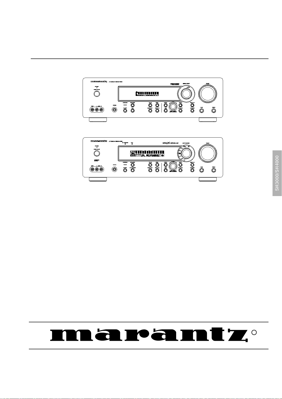
SR3000
SR4000
SECTION PAGE
1. LOCATION OF PRINTED CIRCUIT BOARDS/VERSION VARIATIONS................................................ 1-1
2. TECHNICAL SPECIFICATION................................................................................................................1-3
3. SERVICE TOOL/MEASUREMENT SET UP/SAFETY ............................................................................ 1-5
4. WARNING/HANDLING CHIP COMPONENTS ....................................................................................... 1-6
5. DISMANTLING HINTS ............................................................................................................................ 2-1
6. ABREVIATIONS ......................................................................................................................................2-2
7. WIRING DIAGRAM..................................................................................................................................3-1
8. BLOCK DIAGRAM...................................................................................................................................4-1
9. SERVICE TEST PROGRAM ................................................................................................................... 5-1
10. FRONT BOARD.......................................................................................................................................6-1
11. TUNER BOARD ECO5..........................................................................................................................7B-1
12. TUNER 95 BOARD............................................................................................................................... 7D-1
13. DOLBY PROLOGIC BOARD...................................................................................................................8-1
14. MULTI-CHANNEL DECODING MODULE............................................................................................... 9-1
15. MAINS BOARD...................................................................................................................................... 10-1
16. MONO BOARD...................................................................................................................................... 11-1
17. EXPLODED VIEW ................................................................................................................................. 12-1
18. ELECTRICAL PARTS LIST MONO BOARD ......................................................................................... 13-1
AV Surround Receiver
TABLE OF CONTENTS
Please use this service manual with referring to the user guide (D.F.U) without fail.
SR3000 / SR4000
R
283W855010 ACT
3120 785 22200
First Issue:2000.03
Page 2
MARANTZ DESIGN AND SERVICE
USA
MARANTZ AMERICA, INC.
BRAZIL
PHILIP DA AMAZONIA IND. ELET. ITDA
JAPAN
MARANTZ JAPAN, INC.
EUROPE / TRADING
MARANTZ EUROPE B.V.
TECHNICAL AUDIO GROUP PTY, LTD
CANADA
LENBROOK INDUSTRIES LIMITED
AUSTRALIA
JAMO AUSTRALIA PTY LTD
NEW ZEALAND
WILDASH AUDIO SYSTEMS NZ
THAILAND
MRZ STANDARD CO.,LTD
TAIWAN
PAI- YUING CO., LTD.
MALAYSIA
WO KEE HONG ELECTRONICS SDN. BHD.
AMERICAS
SUPERSCOPE TECHNOLOGIES, INC.
AUSTRALIA
KOREA
MK ENTERPRISES LTD.
SINGAPORE
WO KEE HONG (S) PTE LTD
Using superior design and selected high grade components, MARANTZ company has created the ultimate in stereo sound.
Only original
it is famous.
Parts for your
ORDERING PARTS :
Parts can be ordered either by mail or by Fax.. In both cases, the correct part number has to be specified.
The following information must be supplied to eliminate delays in processing your order :
1. Complete address
2. Complete part numbers and quantities required
3. Description of parts
4. Model number for which part is required
5. Way of shipment
6. Signature : any order form or Fax. must be signed, otherwise such part order will be considered as null and void.
MARANTZ parts can insure that your MARANTZ product will continue to perform to the specifications for which
MARANTZ equipment are generally available to our National Marantz Subsidiary or Agent.
USA
MARANTZ AMERICA, INC
440 MEDINAH ROAD
ROSELLE, ILLINOIS 60172
USA
PHONE : 630 - 307 - 3100
FAX : 630 - 307 - 2687
AMERICAS
SUPERSCOPE TECHNOLOGIES, INC.
MARANTZ PROFESSIONAL PRODUCTS
2640 WHITE OAK CIRCLE, SUITE A
AURORA, ILLINOIS 60504 USA
PHONE : 630 - 820 - 4800
FAX : 630 - 820 - 8103
AUSTRALIA
JAMO AUSTRALIA PTY LTD
1 EXPO COURT, P.O. BOX 350
MT. WAVERLEY VIC 3149
AUSTRALIA
PHONE : +61 - 3 - 9543 - 1522
FAX : +61 - 3 - 9543 - 3677
NEW ZEALAND
WILDASH AUDIO SYSTEMS NZ
14 MALVERN ROAD MT ALBERT
AUCKLAND NEW ZEALAND
PHONE : +64 - 9 - 8451958
FAX : +64 - 9 - 8463554
JAPAN
MARANTZ JAPAN, INC.
35- 1, 7- CHOME, SAGAMIONO
SAGAMIHARA - SHI, KANAGAWA
JAPAN 228-8505
PHONE : +81 42 748 1013
FAX : +81 42 741 9190
Technical
EUROPE / TRADING
MARANTZ EUROPE B.V.
P.O.BOX 80002, BUILDING SFF2
5600 JB EINDHOVEN
THE NETHERLANDS
PHONE : +31 - 40 - 2732241
FAX : +31 - 40 - 2735578
AUSTRALIA
TECHNICAL AUDIO GROUP PTY, LTD
558 DARLING STREET,
BALMAIN, NSW 2041,
AUSTRALIA
PHONE : 61 - 2 - 9810 - 5300
FAX : 61 - 2 - 9810 - 5355
THAILAND
MRZ STANDARD CO.,LTD
746 - 754 MAHACHAI ROAD.,
WANGBURAPAPIROM, PHRANAKORN,
BANGKOK, 10200 THAILAND
PHONE : +66 - 2 - 222 9181
FAX : +66 - 2 - 224 6795
TAIWAN
PAI- YUING CO., LTD.
6 TH FL NO, 148 SUNG KIANG ROAD,
TAIPEI, 10429, TAIWAN R.O.C.
PHONE : +886 - 2 - 25221304
FAX : +886 - 2 - 25630415
BRAZIL
PHILIP DA AMAZONIA IND. ELET. ITDA
CENTRO DE INFORMACOES AO
CEP 04698-970
SAO PAULO, SP, BRAZIL
PHONE : 0800 - 123123
FAX : +55 11 534. 8988
(Discagem Direta Gratuita)
CANADA
LENBROOK INDUSTRIES LIMITED
633 GRANITE COURT,
PICKERING, ONTARIO L1W 3K1
CANADA
PHONE : 905 - 831 - 6333
FAX : 905 - 831 - 6936
SINGAPORE
WO KEE HONG (S) PTE LTD
WO KEE HONG CENTRE
NO.23, LORONG 8, TOA PAYOH
SINGAPORE 319257
PHONE : +65 2544555
FAX : +65 2502213
MALAYSIA
WO KEE HONG ELECTRONICS SDN. BHD.
SUITE 8.1, LEVEL 8, MENARA GENESIS,
NO. 33, JALAN SULTAN ISMAIL,
50250 KUALA LUMPUR, MALAYSIA
PHONE : +60 3 - 2457677
FAX : +60 3 - 2458180
KOREA
MK ENTERPRISES LTD.
ROOM 604/605, ELECTRO-OFFICETEL, 16-58,
3GA, HANGANG-RO, YONGSAN-KU, SEOUL
KOREA
PHONE : +822 - 3232 - 155
FAX : +822 - 3232 - 154
SHOCK, FIRE HAZARD SERVICE TEST :
CAUTION : After servicing this appliance and prior to returning to customer, measure the resistance between either primary AC
cord connector pins ( with unit NOT connected to A C mains and its Power s witch ON ), and the face or Front Panel of product and
controls and chassis bottom.
Any resistance measurement less than 1 Megohms should cause unit to be repaired or corrected before A C po w er is applied, and
verified before it is return to the user/customer.
Ref. UL Standard No. 1492.
In case of difficulties, do not hesitate to contact the Technical
Department at above mentioned address.
991207ACT
Page 3
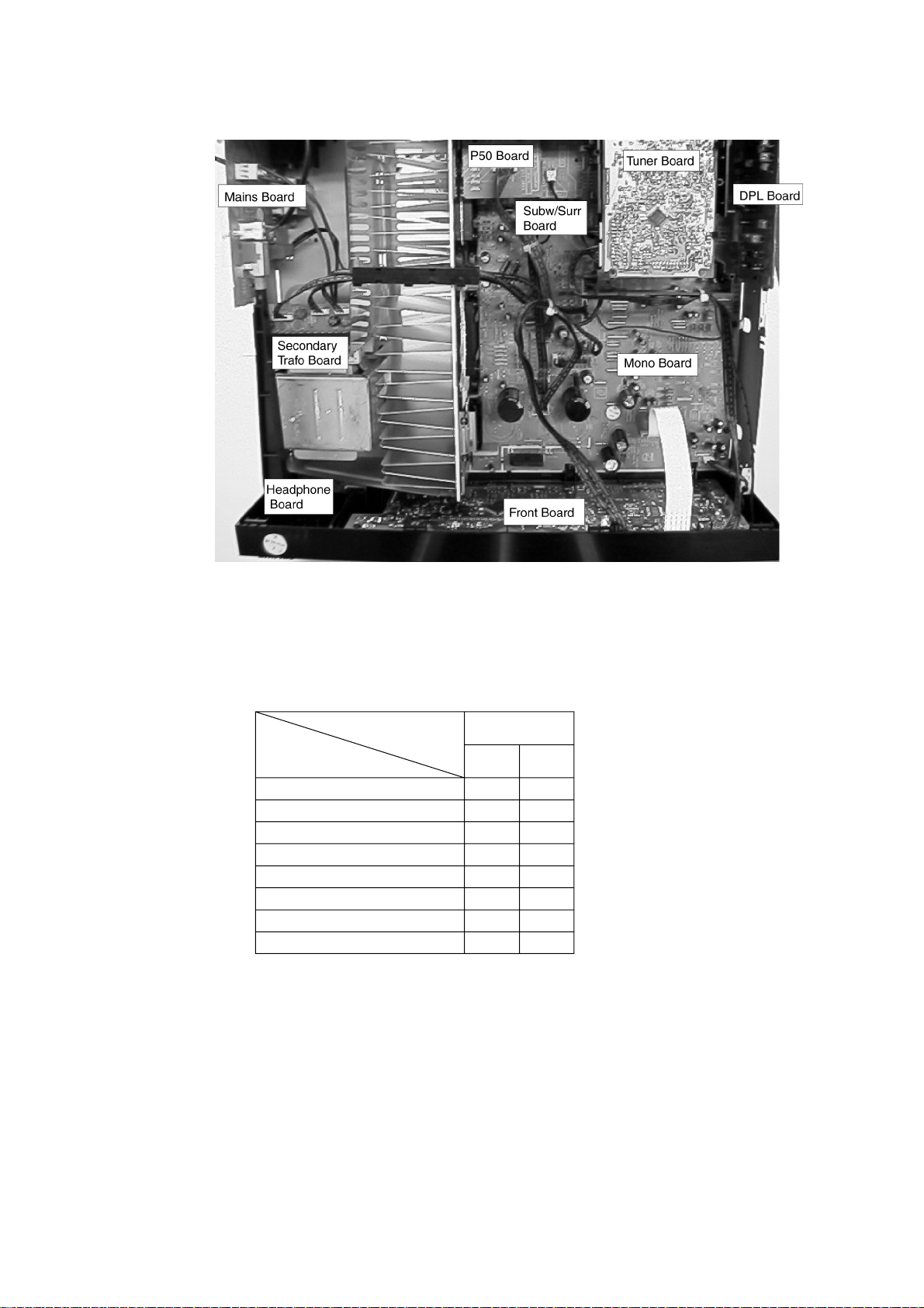
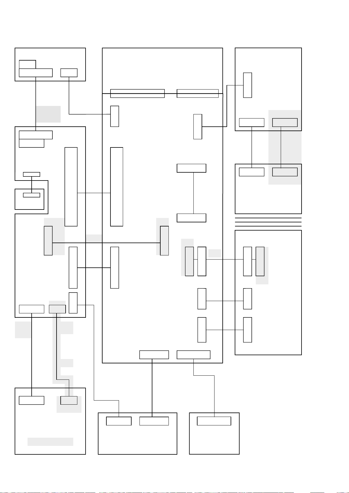
1-1
LOCATION OF PRINTED CIRCUIT BOARDS for SR3000
VERSION V ARIA TIONS
Features &
Board in used
Tuner board - Tuner 95
Tuner board – ECO 5
RDS
P50 code (cinema link)
# Power channels
Center Pre-out
Surround Pre-out
Mains voltage
Type &
version
SR3000
N
x
x
xx
4
x
x
230
U
x
4
x
x
120
Page 4
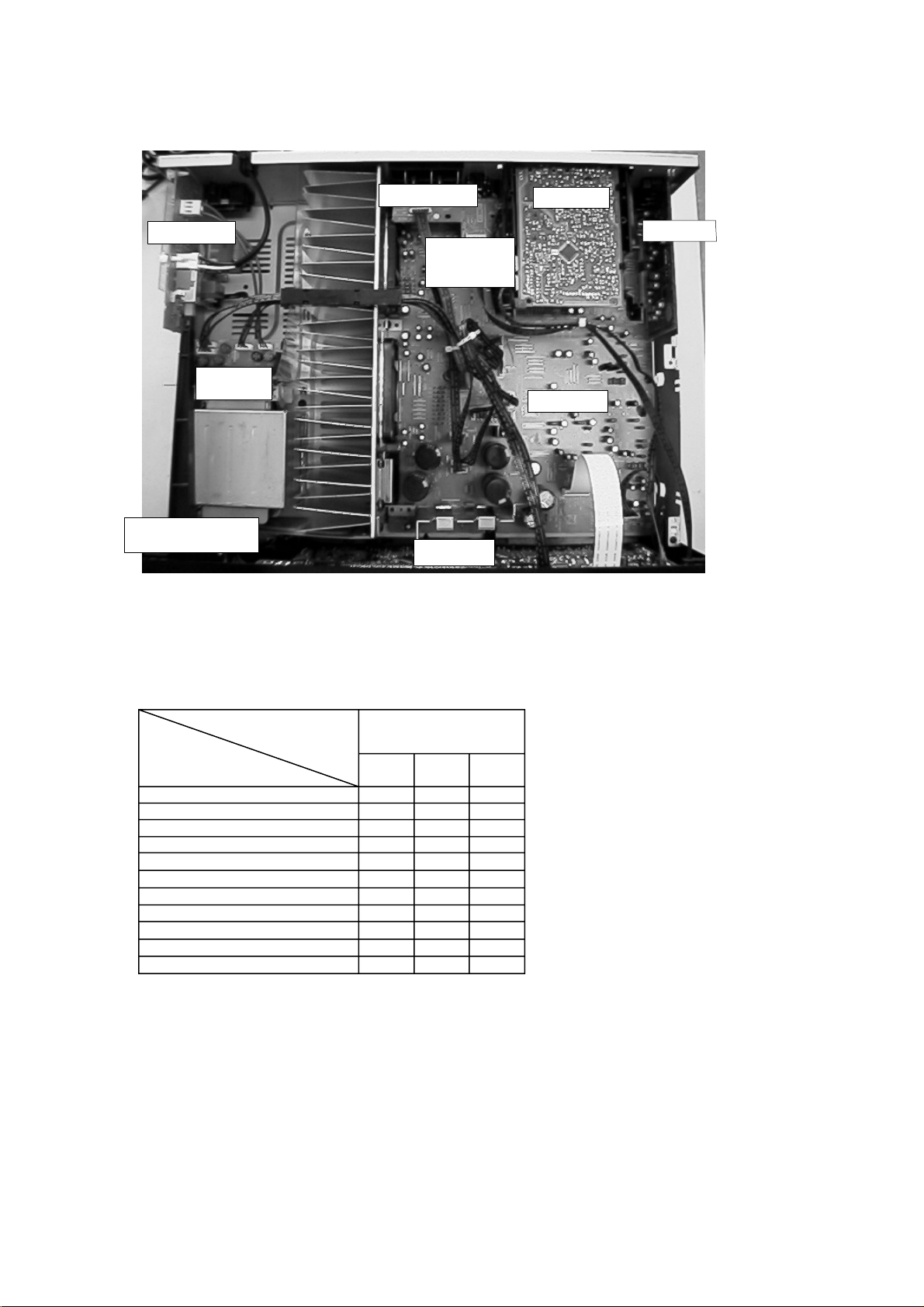
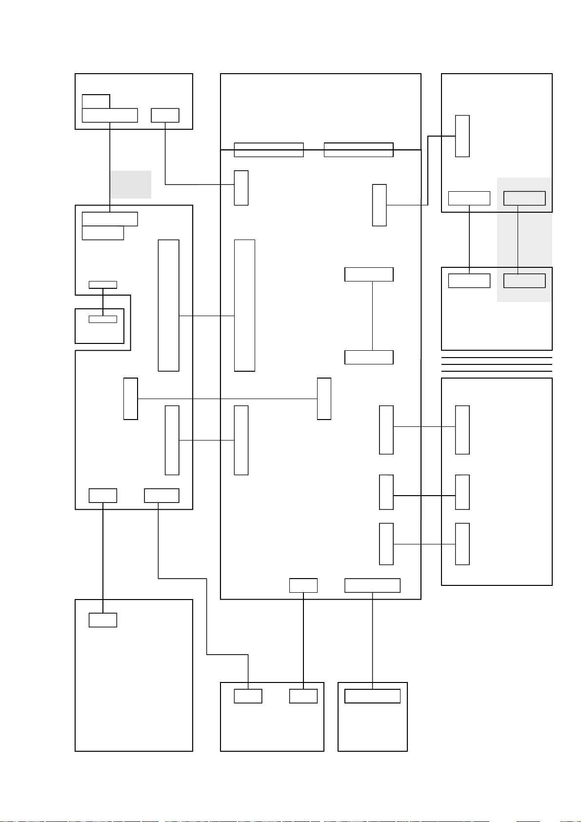
1-2
LOCATION OF PRINTED CIRCUIT BOARDS for SR4000
Mains Board
Secondary
Trafo Board
Headphone & Front AV
Board
Screw Terminal
P50 & Subw. &
Video Selector
Board
Front Board
Tuner Board
MDM Board
Mono Board
VERSION V ARIA TIONS
Features &
Board in used
Tuner board - Tuner 95
Tuner board – ECO 5
RDS
P50 code (cinema link)
AV Front
Video selector
Center pre-out
Subwoofer pre-out
# power channels
Mains voltage
Voltage selector
Type &
Versions
SR4000
NKU
x
x
x
x
xx
xx
xx
xx
xx
55
230 120/230
x
x
x
x
x
5
120
x
Page 5

TECHNICAL SPECIFICATION SR3000
1-3
General
Mains voltage :230V for /N
:120V for /U
Mains frequency : 50Hz for /N
: 60Hz for /U
Power concumption : ≤ 2W at stby
Dimension : 440x138x350 mm
Remote control : RC3000SR
Amplifier
Output power
L+R : 2x50W at 6Ω D= 0,7% (1kHz)
Center : 50W at 6Ω D= 0,7% (1kHz)
Surround : 50W at 2X3Ω D= 0,7% (1kHz)
Distortion (1W)
40Hz -1kHz -20kHz : ≤ 0,05%(L,R,C)
: ≤ 0,2% (Surround ch.)
Headphone : 6,3mm stereo jack with switch
Crosstalk between source —1kHz : ≤ -65dB
(1W) 250Hz – 10kHz : ≤ -60dB
Crosstalk between channels -1kHz : ≤ -45dB
(1W) 250Hz – 10kHz : ≤ -40dB
Frequency response
Left/Right/Center : ≤ 20Hz – ≥20kHz (-3dB)
Surround channel : ≤ 100Hz – ≥7kHz (-3dB)
Power stage protection : Shortcircuit
: DC (Vout ≥10V)
T emperature : T ransf ormer (≥140˚ Celcius)
: Heatsink (≥140˚ Celcius)
Input sensitivity
CD : 250mV impedance ≥ 47kΩ
CDR/TAPE : 250mV impedance ≥ 47kΩ
VCR : 250mV impedance ≥ 47kΩ
TV : 250mV impedance ≥ 47kΩ
Output sensitivity
CDR/TAPE : 250mV impedance ≤ 1kΩ
VCR : 250mV impedance ≤ 1kΩ
Output sensitivity (variable)
Center pre-out : 800mV impedance ≤ 1kΩ
Surround pre-out : 800mV impedance ≤ 1kΩ
Equalizer
Loudness
(volume ≤ -20dB Ref: 1kHz=0dB) : Bass 100Hz +6 dB
: Treble 10kHz +3 dB
Tone control (Ref: 1kHz=0dB)
: Bass 100Hz -10dB ➔+10dB
: Treble 10kHz -10dB ➔+10dB
Dolby Pro Logic
Stereo bypass from : Lt , Rt into Left, Right
Dolby Pro-logic decoding : Lt , Rt into Left, Right, Center,
: Surround
Dolby 3 stereo decoding : Lt , Rt into Left, Center, Right
Dolby Phantom decoding : Lt , Rt into Left, Right, Surround
(Phantom = no center speaker)
Hall : Lt , Rt into Left, Surround, Right
Surround delay : variable
Center mode : Large , small
Testtone
Tuner
RDS : Only in /N
FM
Tuning range : 87.5 – 108MHz
Grid : 50kHz for /N
: 100kHz for /U
IF frequency : 10.7MHz ±25kHz
Aerial input : 75 Ω coaxial
Sensitivity at 26dB S/N : ≤ 7µv
Selectivity at 600kHz bandwidth : ≥ 50dB
Inmage rejection : ≥ 25dB [ 75dB]
Distortion at RF=1mV,dev.75kHz : ≤ 3% [ 2%]
-3dB Limiting point : ≤ 7µV
Crosstalk at RF=1mV,dev.40kHz : ≥18dB [ 26dB]
MW
Tuning range : 531 - 1602kHz for /N
: 530 - 1700kHz for /U
Grid : 9kHz for /N
: 10kHz for /U
IF frequency : 450kHz ±1kHz
Aerial input : Loop
Sensitivity at 26dB S/N : ≤ 4.0mV/m
Selectivity at 18kHz bandwidth : ≥ 18dB
IF rejection : ≥ 45dB
Inmage rejection : ≥ 28dB
Distortion at RF=50mV,m=80% : ≤ 5%
LW only in /N
Tuning range : 153 - 279kHz
Grid : 3kHz
IF frequency : 450kHz ±1kHz
Aerial input : Loop
Sensitivity at 26dB S/N : ≤ 7.0mV/m
Selectivity at 18kHz bandwidth : ≥ 24dB
IF rejection : ≥ 26dB
Inmage rejection : ≥ 35dB
Distortion at RF=50mV,m=80% : ≤ 5%
[...] Values indicated are for “Tuner 95 Board” only
* Setting is software controlled
DSC settings 100Hz 1kHz 10kHz
Personal dB 0 0 0
Movie dB + 4 +2 +4
Speech dB - 4 +2 - 2
Music dB + 4 - 2 +2
Multimedia dB + 8 0 +6
Page 6

TECHNICAL SPECIFICATION SR4000
General
Mains voltage :230V for /N
:110V/240V switchable for /K
: 120V for /U
Mains frequency : 50Hz for /N
: 50/60Hz for /K
: 60Hz for /U
Power concumption : ≤ 2W at stby
Dimension. wxhxd : 440x138x350 mm
Remote control : RC4000SR
Amplifier
Output power
L+R : 2x100W at 6Ω D= 0,7% (1kHz)
Center : 100W at 6Ω D= 0,7% (1kHz)
Surround Left : 50W at 6Ω D= 0,7% (1kHz)
Surround Right : 50W at 6Ω D= 0,7% (1kHz)
Distortion (5W)
40Hz -1kHz : ≤ 0,05%
20kHz : ≤ 0,2%
Headphone : 6,3mm stereo jack with switch
1-4
DSC settings 100Hz 1kHz 10kHz
Personal dB 0 0 0
Movie dB + 4 +0 +4
Speech dB - 4 +2 - 2
Music dB + 4 - 2 +2
Multimedia dB + 8 0 +6
Multi Channel Decoder
MPEG5.1 / MPEG 7.1 (7.1 downmix to 5.1)
Dolby Digital (AC-3)
Linear PCM
Automatic audio/data type detection (AC-3,MPEG-2,PCM)
Dolby Pro Logic
MPEG-2 dual mono channel selection I/II
MPEG-2 dual stereo channel selection I/II
Virtual Dolby Surround (422/423)
Virtual MPEG Digital (522/523)
Virtual Dolby Digital (522/523)
Digital Bass Management
Parallel Stereo Downmix
Four Stereo (224)
Volume Control
Noise Generator (test tone)
Surround mode selector
Delay C and SL and SR
Crosstalk between source —1kHz : ≤ -65dB
(1W) 250Hz – 10kHz : ≤ -60dB
Crosstalk between channels -1kHz : ≤ -45dB
(1W) 250Hz – 10kHz : ≤ -40dB
Frequency response
: ≤ 20Hz – ≥ 20kHz (-3dB)
Power stage protection : Shortcircuit
: DC (Vout ≥ 10V)
T emper ature : Transformer ( ≥140˚ Celcius)
: Heatsink ( ≥ 140˚ Celcius)
Input sensitivity
Phono : 5mV impedance 47kΩ/220pF
CD : 250mV impedance ≥ 47kΩ
CDR/TAPE : 250mV impedance ≥ 47kΩ
VCR : 250mV impedance ≥ 47kΩ
TV : 250mV impedance ≥ 47kΩ
SAT : 250mV impedance ≥ 47kΩ
FRONT AV : 250mV impedance ≥ 22kΩ
Output sensitivity
CDR/TAPE : 250mV impedance ≤ 1kΩ
VCR : 250mV impedance ≤ 1kΩ
Output sensitivity (variable)
Subwoofer pre-out : 800mV impedance ≤ 1kΩ
Center pre-out : 800mV impedance ≤ 1kΩ
Video Selector
Input sensitivity
DVD/VCR/TV/Front AV : 1 Vpp impedance 75Ω
Output sensitivity
Monitor/VCR : 1 Vpp impedance 75Ω
Frequency response : ≤ 50Hz ➔ ≥ 6MHz
Equalizer
Loudness
(volume ≤ -20dB Ref: 1kHz=0dB) : 100Hz +6 dB
: 10kHz +3 dB
Tone control (Ref: 1kHz=0dB)
: Bass 100Hz -9dB ➔+9dB
: Treble 10kHz -9dB ➔+9dB
Tuner
RDS : Only in /N
FM
Tuning range : 87.5 – 108MHz
Grid : 50kHz
: 100kHz only for /U
: 50 & 100kHz for /K
IF frequency : 10.7MHz ±25kHz
Aerial input : 75 Ω coaxial
: 300 Ω clickfit only for /U
Sensitivity at 26dB S/N : ≤ 7µv
Selectivity at 600kHz bandwidth : ≥ 50dB
Image rejection : ≥ 75dB
: ≥ 25dB only for /U, K
Distortion at RF=1mV,dev.75kHz : ≤ 2%
: ≤ 3% only for /U, K
-3dB Limiting point : ≤ 7µV
Crosstalk at RF=1mV,dev.40kHz : ≥ 26dB
: ≥ 22dB only for /U, K
MW
Tuning range : 522 - 1611kHz for /N
: 531 - 1602kHz for/K
: 530 - 1700kHz for/K
: 530 - 1700kHz for /U
Grid : 9kHz for /N
: 9 & 10kHz for /K
: 10kHz for /U
IF frequency : 450kHz ±1kHz
Aerial input : Loop
Sensitivity at 26dB S/N : ≤ 4.0mV/m
Selectivity at 18kHz bandwidth : ≥ 18dB
IF rejection : ≥ 45dB
Image rejection : ≥ 28dB
Distortion at RF=50mV,m=80% : ≤ 5%
LW only in /N
Tuning range : 153 - 279kHz
Grid : 3kHz
IF frequency : 450kHz ±1kHz
Aerial input : Loop
Sensitivity at 26dB S/N : ≤ 6mV/m
Selectivity at 18kHz bandwidth : ≥ 22dB
IF rejection : ≥ 26dB
Image rejection : ≥ 35dB
Distortion at RF=50mV,m=80% : ≤ 5%
* Setting is software controlled
Page 7
SER VICE TOOL
Audio Signals Test Disc 1 ................................. 4822 397 30184
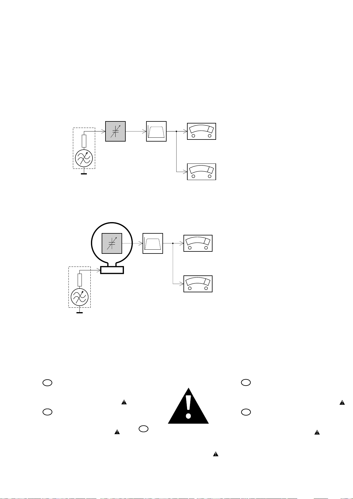
MEASUREMENT SETUP
Tuner FM
1-5
Bandpass
LF Voltmeter
e.g. PM2534
RF Generator
e.g. PM5326
DUT
250Hz-15kHz
e.g. 7122 707 48001
Ri=50Ω
S/N and distortion meter
e.g. Sound Technology ST1700B
Use a bandpass filter to eliminate hum (50Hz, 100Hz) and disturbance from the pilottone (19kHz, 38kHz).
Tuner AM (MW,LW)
RF Generator
e.g. PM5326
Ri=50Ω
DUT
Frame aerial
e.g. 7122 707 89001
Bandpass
250Hz-15kHz
e.g. 7122 707 48001
LF Voltmeter
e.g. PM2534
S/N and distortion meter
e.g. Sound Technology ST1700B
To avoid atmospheric interference all AM-measurements have to be carried out in a Faraday´s cage.
Use a bandpass filter (or at least a high pass filter with 250Hz) to eliminate hum (50Hz, 100Hz).
SAFETY
GB
Safety regulations require that the set be restored to its
original condition and that parts which are identical with
those specified be used.
Safety components are marked by the symbol
F
Les normes de sécurité exigent que l`appareil soit remis
à l`état d`origine et que soient utilisées les pièces de
rechange identiques à celles spécifiées.
Les composants de sécurité sont marqués
D
Bei jeder Reparatur sind die geltenden Sicherheitsvorschriften zu beachten. Der Originalzustand des Gerätes
darf nicht verändert werden. Für Reparaturen sind Originalersatzteile zu verwenden.
Sicherheitsbauteile sind durch das Symbol markiert.
SAFETY
NL
Veiligheidsbepalingen vereisen, dat het apparaat in zijn
oorspronkeliijke toestand wordt teruggebracht en dat
onderdelen, identiek aan de gespecificeerde, worden toegepast.
De Veiligheidsonderdelen zijn aangeduid met het symbool
I
Le norme di sicurezza estigono che l´apparecchio venga
rimesso nelle condizioni originali e che siano utilizzati i
pezzi di ricambiago identici a quelli specificati.
Componenty di sicurezza sono marcati con
Page 8
WARNING
1-6
GB WARNING
All ICs and many other semiconductors are susceptible to
electrostatic discharges (ESD). Careless handling during
repair can reduce life drastically.
When repairing, make sure that you are connected with the
same potential as the mass of the set via a wristband with
resistance. Keep components and tools at this potential.
F ATTENTION
Tous les IC et beaucoup d´autres semi-conducteurs sont
sensibles aux décharges statiques (ESD). Leur longévite
pourrait être considérablement écourtée par le fait qu´aucune
précaution nést prise à leur manipulation.
Lors de réparations, s´assurer de bien être relié au même
potentiel que la masse de l´appareil et enfileer le bracelet
serti d´une résistance de sécurité.
Veiller à ce que les composants ainsi que les outils que l´on
utilise soient également à ce potentiel.
GB
AVAILABLE ESD PROTECTION EQUIPMENT :
anti-static table mat large 1200x650x1.25mm 4822 466 10953
anti-static wristband 4822 395 10223
connection box (3 press stud connections, 1M ) 4822 320 11307
extendible cable (2m, 2M , to connect wristband to connection box) 4822 320 11305
connecting cable (3m, 2M , to connect table mat to connection box) 4822 320 11306
earth cable (1M , to connect any product to mat or to connection box) 4822 320 11308
KIT ESD3 (combining all 6 prior products - small table mat) 4822 310 10671
wristband tester 4822 344 13999
D
Alle ICs und viele andere Halbleiter sind empfindlich
gegenüber elektrostatischen Entladungen (ESD).
Unsorgfältige Behandlung im Reparaturfall kann die
Lebensdauer drastisch reduzieren.
Sorgen Sie dafür, daß sie im Reparaturfall über ein Pulsarmband mit Widerstand mit dem Massepotential des
Gerätes verbunden sind.
Halten Sie Bauteile und Hilfsmittel ebenfalls auf diesem
Potential.
ESD
WARNUNG
small 600x650x1.25mm 4822 466 10958
NL WAARSCHUWING
Alle IC´s en vele andere halfgeleiders zijn gevoelig voor
electrostatische ontladingen (ESD).
Onzorgvuldig behandelen tijdens reparatie kan de levensduur
drastisch doen vermindern. Zorg ervoor dat u tijdens reparatie
via een polsband met weerstand verbonden bent met hetzelfde
potentiaal als de massa van het apparaat.
Houd componenten en hulpmiddelen ook op ditzelfde potentiaal.
I
Tutti IC e parecchi semi-conduttori sono sensibili alle scariche
statiche (ESD).
La loro longevità potrebbe essere fortemente ridatta in caso di
non osservazione della più grande cauzione alla loro
manipolazione. Durante le riparationi occorre quindi essere
collegato allo stesso potenziale che quello della massa
delápparecchio tramite un braccialetto a resistenza.
Assicurarsi che i componenti e anche gli utensili con quali si
lavora siano anche a questo potenziale.
AVVERTIMENTO
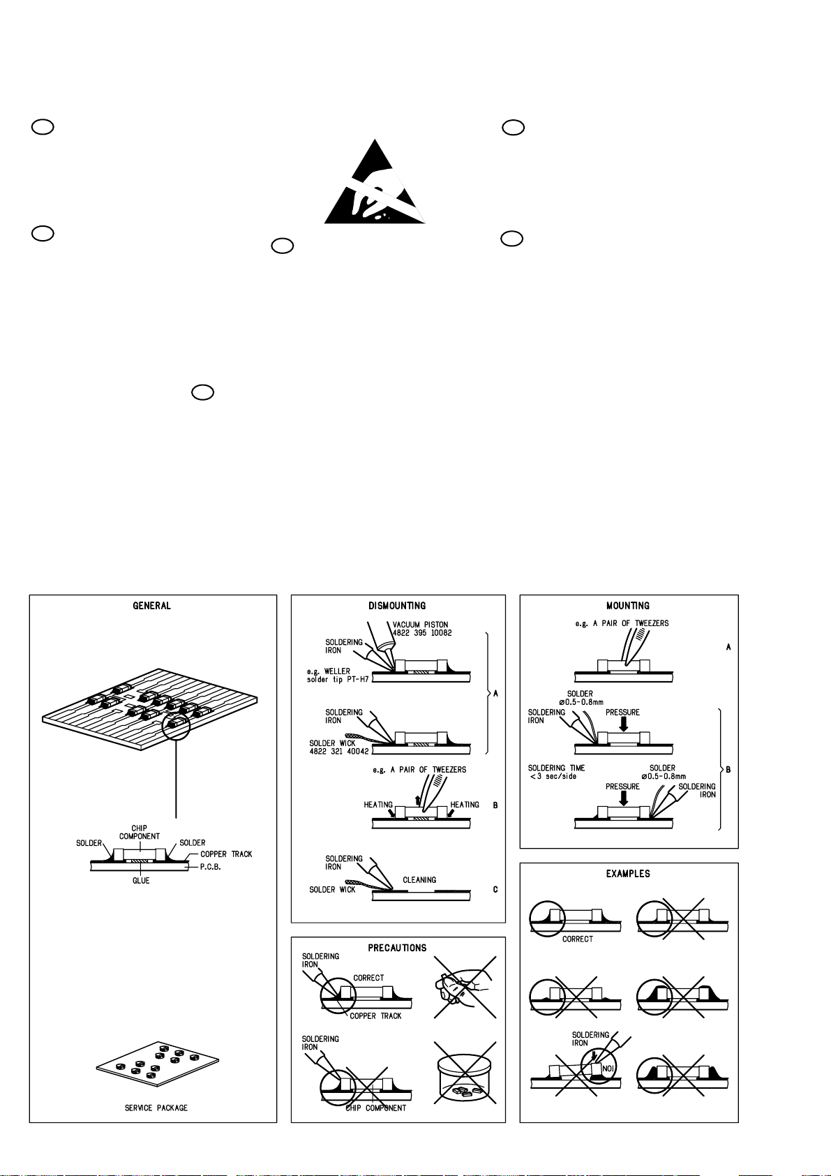
HANDLING CHIP COMPONENTS
Page 9
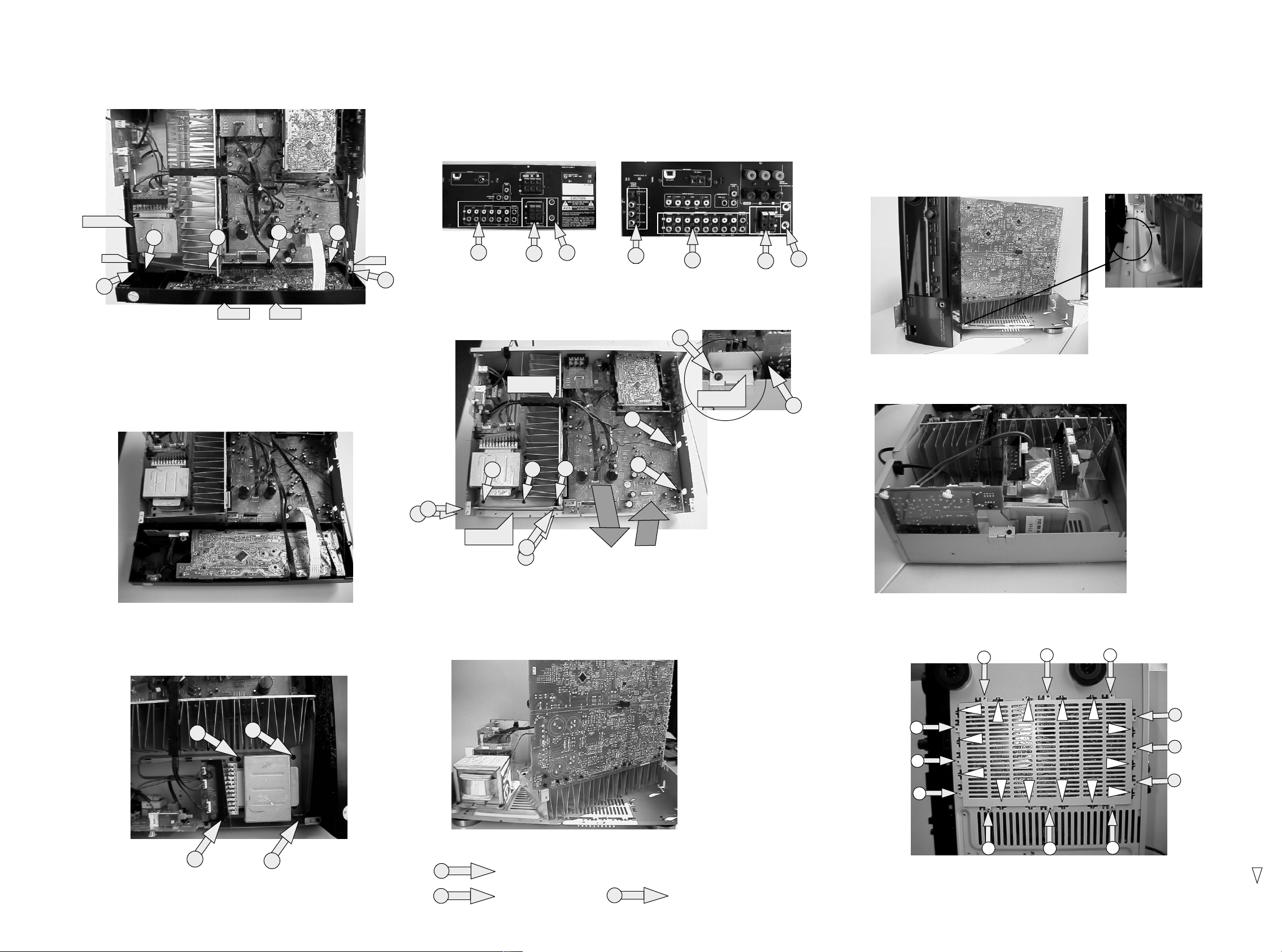
DISMANTLING HINTS
2-1 2-1
Dismantling of Front
Power rod
1
snap
2
1) Remove top cover
2) Remove power rod
3) Remove 6 x screw as shown in picture 1
4) Release two snaps (left & right side front)
5) Release two snaps on the bottom side front
6) Tipp down front as shown in picture 2
1
snap
1
snap
1
picture 1
snap
Dismantling of mono board
1) Remove front . See picture 1
2) Remove whole front (disconnect the wires on the mono
board coming from front)
2
2
3) Remove 8 (SR3000) x screws shown in mentionned aria . See picture 3a
3) Remove 12 (SR4000) x screws shown in mentionned aria . See picture 3b
1
2
cable-sleeve
1
3
picture 3a
(SR3000)
1
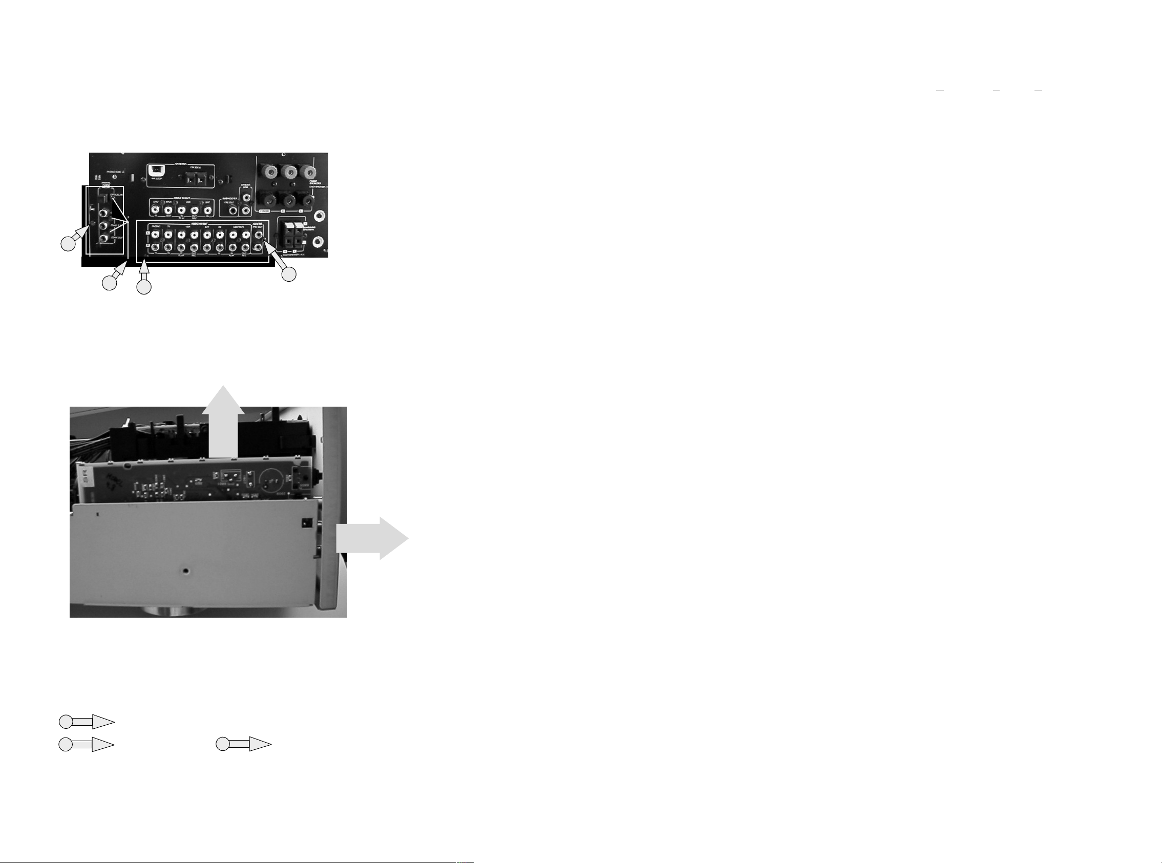
Service position monoboard
1) Bring front in position as shown in picture 6
2) Snap nok of front in bottom to make front stable . See picture 7
3) Connect front wiring back to monoboard.
*The tuner module doesn't have to be connected. Use an other source (pe.CD)
2
2
picture 3b
(SR4000)
1
Dpl bracket
1
(SR3000 Only)
1
3
2
3
picture 4a
picture 7
picture 6
Service position main trafo
Dismantling of mainstrafo
1
1
1
1
2
Metal bracket
1
1
picture 4
4) Remove DPL bracket. See picture 4a (SR3000 Only)
5) Remove wires out the cable-sleeve.
6) Remove 7 x screw and remove metal bracket
picture 2
7) Remove 2 x screw on mono board . See pictue 4
8) Remove mono board as shown arrow 1 & 2 . See picture 4
9) Bring the mono board in the service position as shown in picture 5
1
1) Put main trafo as shown in picture 9
Handling service cover
1
1
1
1
1
picture 9
1
1
1
1
1
1
1) Remove power rod
2) Remove 4x screw as shown in picture 8
picture 8
Legend
picture 5
1
1
1
picture 10
1
2
= Torx M3x6mm ( screw with big head )
= T orx 3x10mm
3
= T orx M3x6mm
1) To open the service cover cut 14 x lugs between cover and bottem . See picture 10
2) To close the service cover put 12 x screw in mentionned holes. See picture 10
Service codenumber 12x Torx M3x6mm screw with big head = 4822 502 14659
( )
Page 10
2-2
2-2
DISMANTLING HINTS
Dismantling of MDM module (SR4000 Only)
1) Remove all the screws mentionned in the arial . See picture 11
3
2
2) Remove backplate a little backwards. See arrow 1 (picture 12)
3) Pull module out the set as shown in picture 12
3
5x
ABBREVIATIONS
A
ac 0VA AC 0 Voltage
ac 10VB AC 10 Voltage
ac 110VB AC 110 Voltage
ac 120VB AC 120 Voltage
ac gnd AC ground
ac h1 AC high voltage 1
ac h2 AC high voltage 2
ac l1 AC low voltage 1
ac l2 AC low voltage 2
ac1 AC voltage 1
ac2 AC voltage 2
ac3 AC voltage 3
amp lr on Amplifier Left - Right On
amp mute c s Amplifier mute center surround
amp mute c s sub Amplifier mute center surround
subwoofer
amp mute lr Amplifier mute Left - Right
2
picture11
amp pd Amplifier power down
amp prot Amplifier protection
amp s on Amplifier surround On
amp stby Amplifier Standby
av gnd Audio ground
av l Audio Left
av r Audio Right
A/V Audio/Video
D
d gnd Dolby ground
dd req Dolby decoder request
dpl c out Dolbyprologic Center out
dpl clk Dolbyprologic clock
dpl gnd Dolbyprologic ground
dpl l in Dolbyprologic Left in
dpl l out Dolbyprologic Left out
dpl r in Dolbyprologic Right in
dpl r out Dolbyprologic Right out
dpl s Dolbyprologic surround
dpl sub Dolbyprologic subwoofer
F
f1 Filament 1
1
f2 Filament 2
fmute Fast mute
G
gnd d Ground digital
gnd s Ground signal
H
hp gnd Headphone ground
picture12
hp l Headphone Left
hp on Headphone On
hp r Headphone Right
hst Heatsink temperature
M
mdm Multi channel Decoding Module
mdm c out — Center out
mdm gnd — ground
mdm l dmix — Downmix Left
mdm l in — Left in
mdm l out — Left out
mdm r dmix — Downmix Right
mdm r in — Right in
mdm r out — Right out
mdm req — request
mdm rst — reset
mdm scl — I2C clock
mdm sda — I2C data
mdm sl out — surround Left out
mdm sr out — surround Right out
mdm sub out — subwoofer out
mfd Mains failure detection
P
p gnd P50 ground
p p50 Cinema link P50 code
S
s gnd Surround ground
sofac scl Sofac I2C clock
sofac1 sda1 Sofac 1 I2C data1
sofac2 sda2 Sofac 2 I2C data2
ss ce Source selector chipenable
ss clk Source selector clock
ss data Source selector data
surr pre-out Surround pre-out
T
tu clk Tuner clock
tu da Tuner data
tu en Tuner enable
tu gnd Tuner ground
tu l Tuner Left
tu r Tuner Right
tu rds Tuner RDS
tu stereo Tuner stereo
V
v gnd Video ground
v scl Video I2C clock
v sda Video I2C data
v sig Video signal
v sub sur Video subwoofer surround
Legend
L
ls c Loudspeaker Center
1
2
= Torx M3x6mm ( screw with big head )
= T orx 3x10mm
3
= T orx M3x6mm
ls gnd Loudspeaker ground
ls l Loudspeaker Left
ls r Loudspeaker Right
Page 11
WIRING DIAGRAM SR3000
3-1
4 XH
6 XH 4 XH
tu_stereo
tu_clk
tu_da
tu_en
tu_rds
tu_gnd
8401
6 DM
4 DM
only in RDS
1433
RDS version
FRONT
1440
2 DM
8405
2 DM
1441
Stby Led
1439
hp_gnd
hp_ r
hp_ l
1436
7 DM
hp_on
hp_gnd
hp_ r
hp_ l
8410
8408
TUNER
1401
only in
RDS version
not in
1410
3 DM
1426
1434
2 EH
tu_l
tu_gnd
tu_r
+12
8206
15 FFC
8 DM
p_p50
p_gnd
8002
8406
8402
dpl
---Left out
1511
1520
1257
DOLBY PRO LOGIC
---Ground
---Right out
---Ground
---Center
---Ground
---Surround
---Surround
---Subwoofer out
1701 1702
9 JQ
XH
1524 1522
4 DM
MONO
ss ce
ss clk
ss data
sofac scl
sofac1 sda1
sofac2 sda2
dpl clk
amp s on
amp lr on
d gnd
15 FFC
amp prot
amp mute lr
amp mute c s
dd reset
dd req
amp stby
amp pd
+5
+5D
ground d
8 EH
-30
f1
f2
1527
2 DM
dpl
3 EH
1601
---Data
---Request
---Clock
--- + 9V
9 JQ
8201
1302
---Ground
--- + 5V
---Right In
XH
1254
1265
5 DM
5 DM
1902
6 DM
---Ground
---Left In
4 EH
-VL
ls_gnd
ls_gnd
gnd
+VL
1251
1253
3 EH
1255
8012
5 EH
4 EH
8008
8010
8011
MAINS
relay
mfd
+v
4 EH
gnd_s
0051
1064 1063
2 VH 4 VH
ac_A
ac_fuse
8077 8076
2 SDN
8077
8076
PRIM. TRAFO
SEC. TRAFO
ac_h1
ac_l1
ac_gnd
5 EH
ac_l2
ac_h2
1073
ac1
ac2
3 EH
ac3
1071
f1
f2
amp_prot
4 EH
gnd_s
1072
ac_0VA
ac_120VB
ac_110VB
ac_10VB
4 SDN
only/K
7 DM
1425
HEADPHONE
8003
8501
2 EH
1561
P50 Board
2 EH
1553
surr.pre out
s_gnd
ls_l
ls_gnd
ls_r
ls_gnd
ls_c
ls_gnd
8204
6 DM
1303
Click fit
Terminal
Page 12
WIRING DIAGRAM SR4000
3-2
4 XH
6 XH 4 XH
tu_stereo
tu_clk
tu_da
tu_en
tu_rds
tu_gnd
8401
6 DM
4 DM
only in RDS
1433
RDS version
FRONT
1440
2 DM
8405
2 DM
1441
Stby Led
1436
7 DM
av_ r
av_gnd
av_ l
hp_ on
hp_gnd
hp_ r
hp_ l
8410
8408
7 DM
1425
TUNER
1401
RDS version
not in
1410
1437
av_ r
av_gnd
av_ l
hp_ gnd
hp_ r
6 DM
hp_ l
1435
2 DM
1426
v_gnd
v_sig
only in
8407
2 DM
1427
tu_l
tu_gnd
tu_r
+12
8206
15 FFC
8 DM
6 EH
1402
8002
8409
8402
p_p50
p_gnd
v_sda
v_scl
v_gnd
v_sig
mdm
1511
1257
8004
---Left out
4 DM
1520
8 EH
---Ground
12/JQ
15 FFC
---Right out
---Ground
---Center out
---Ground
---Surround left
---Surround right
XH
ssce
ssclk
ssdata
sofac scl
sofac1 sda1
sofac2 sda2
dpl clk
amp s on
amp lr on
d ground
amp prot
amp mute lr
amp mute c/s/ sub
dd reset
dd req
amp stby
amp pd
+5
+5D
ground d
-30
f1
f2
8502
MDM
---Subwoofer out
---Downmix left
---Downmix gnd
---Downmix right
1523 1521
MONO
1515
6 EH
1526
5 DM
+5
+12
v_gnd
subw.pre out
s_gnd
1701
mdm
1302
---Reset
---Request
1265
5 DM
8201
5 DM
1902
1252
---Sda
---Scl
9JQ
5EH
6 DM
---Ground
XH
1254
4 EH
-VL
ls_gnd
ls_gnd
gnd
+VL
1251
1253
1255
--- + 5V
---Right In
8012
5 EH
3 EH
4 EH
8205
---Ground
---Left In
8009
8008
8010
8011
ls_l
ls_gnd
ls_r
ls_gnd
ls_c
ls_gnd
1702
MAINS
relay
mfd
+v
4 EH
gnd_s
0051
1064 1063
2 VH 4 VH
ac_A
ac_fuse
8077 8076
2 SDN
8077
8076
PRIM. TRAFO
SEC. TRAFO
ac_h1
ac_l1
5 EH
1073
3 EH
1071
4 EH
1072
ac_gnd
ac_l2
5 EH
ac_h2
1074
ac1
ac2
ac3
f1
f2
amp_prot
gnd_s
ac_0VA
ac_120VB
ac_110VB
ac_10VB
4 SDN
only/K
HEADPHONE
+
FRONT AV
6 EH
1560
5 EH
1552
P50 Board &
VIDEO SELECTOR
6 DM
1305
SCREW TERM
Page 13
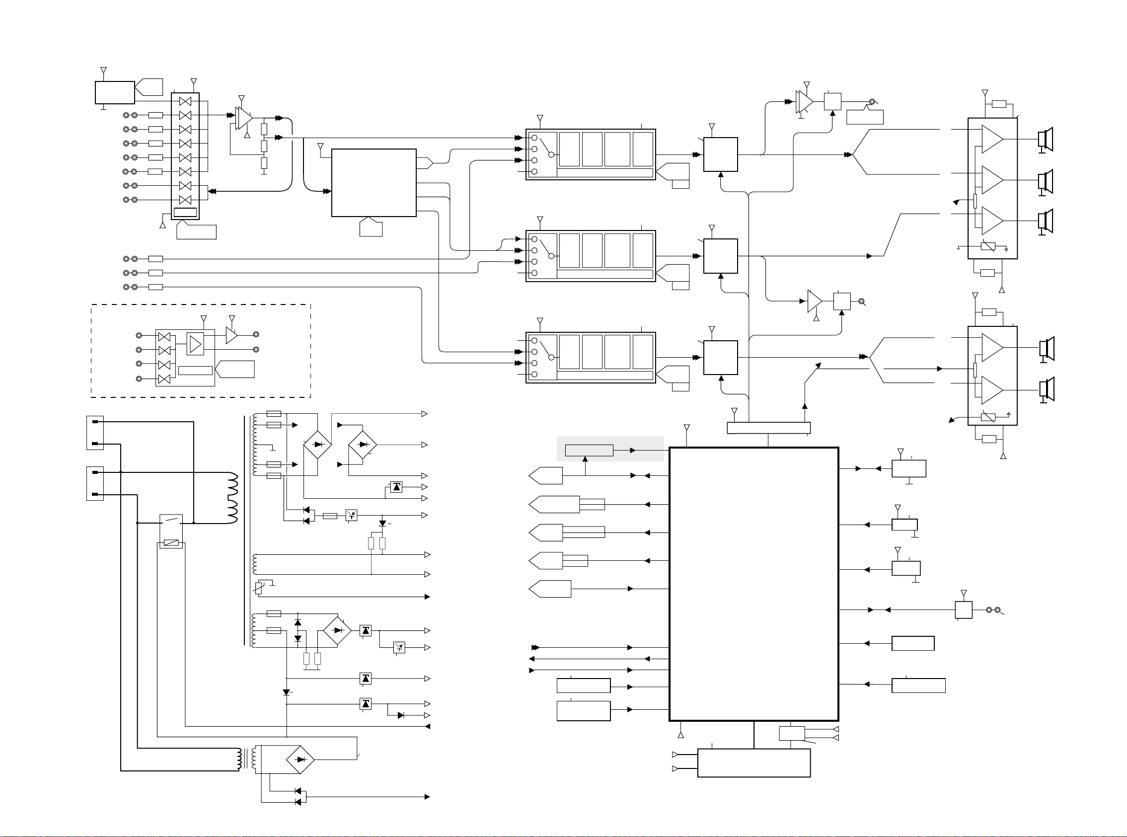
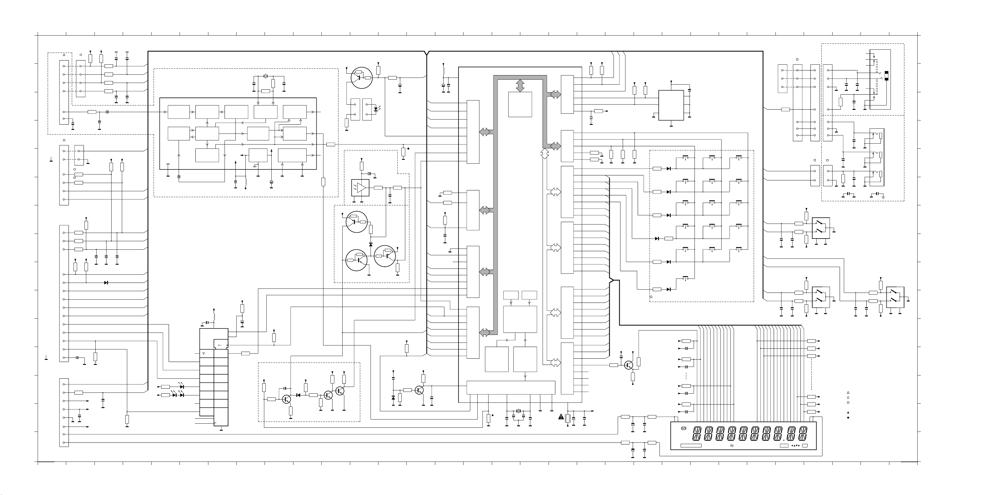
BLOCK DIAGRAM SR3000
+12V
ECO5/
Tuner 95
CD
CDR/TAPE
VCR
TV
FRONT AV
CDR/Tape
VCR
6CH/DVD Input
Front L/R
C/SUB
SL/SR
VIDEO SELECTOR
DVD In
VCR In
TV In
Front AV In
Outlet
Mains
Tuner
control
ATT
ATT
ATT
ATT
ATT
ATT
ATT
ATT
-12V
7803
7501
o o
+12V
LOGIC
Source selctor
control
+5 +12
Logic control
+12V
7503
-12V
Record path
7801
7802
Video sel.
control
MONITOR OUT
VCR OUT
6253
6274
6275
6257
6261
6268
4-1 4-1
+12V
+9V
1258
0,33E
DPL
DECODER
L/R
DPL
control
7907/7908
7257
7258
6258/6259
6262/6263
6260
6265
6267
+V
6252
6276
SUB
7905
L
R
C
S
6649
+VH
+VL
-VL
-12V
-VH
-30V
F1
F2
protection 2
+12V
+9V
+5V
+5Vp
+5Vmute
AMP STBY
Sub
C/Sub
C/Sub
+9V
+9V
+9V
Tuner
control
Source selctor
control
DPL
control
Sofac
control
Headphone
sense
protection1,2
Relay
MFD
1421
Menu navigator
1422
Source selector
encoder
IN
VOL
GAIN
LOUD
LOGIC CONTROL
IN
VOL
GAIN
LOUD
LOGIC CONTROL
IN
VOL
GAIN
LOUD
LOGIC CONTROL
only/N1B
RDS DECODER
7404
RDS Info
Stereo/Clock/Data/CE
SSCE
SSCLK
SSData
Reset
SCL/SDA
Request
SDA1
SCL
SDA2
BASS
MID
TREBLE
BASS
MID
TREBLE
BASS
MID
TREBLE
RDS Data/Clk
7641
SPKR
ATT
7642
SPKR
ATT
7643
SPKR
ATT
-30V
F1
F2
Sofac
control
Sofac
control
7651/7652
7657
SDA1
7653/7654
7658
SDA1
7655/7656
7658
Sofac
control
SDA2
+5Vp
+5Vmute
MUTE
+5Vmute
MUTE
+5Vmute
MUTE
+5Vp
7415
µP
7414
Display
Mute
control
Shift register
Amp-ON
Current
buffer
7601
7660-2
-12V
7412
7621/7622
Mute
Headphone
ON
7662
Mute
Amp-ON
+5Vp
-30V
7416/7417/7418
Headphone
1424
Subwoofer pre-out
1550
+5Vp
CLK
DATA
Eeprom
+5Vp
Reset
+5Vp
IR Eye
Key Matrix
1423
Volume control
Amp-ON
protection 1
7405
7409
7403
L
R
C
SL
Amp-ON
SR
+VL
+5D
RC5
7419/7421
+VH
3301
+
-
+
-
+
-
PTC
3328
-VH
3901
+
-
+
-
PTC
3915
7301
Left
Right
Center
hst
7901
Surround
Left
Surround
Right
hst
-VL
Remote control
1541
MFD
MDI 04-06-99
Page 14
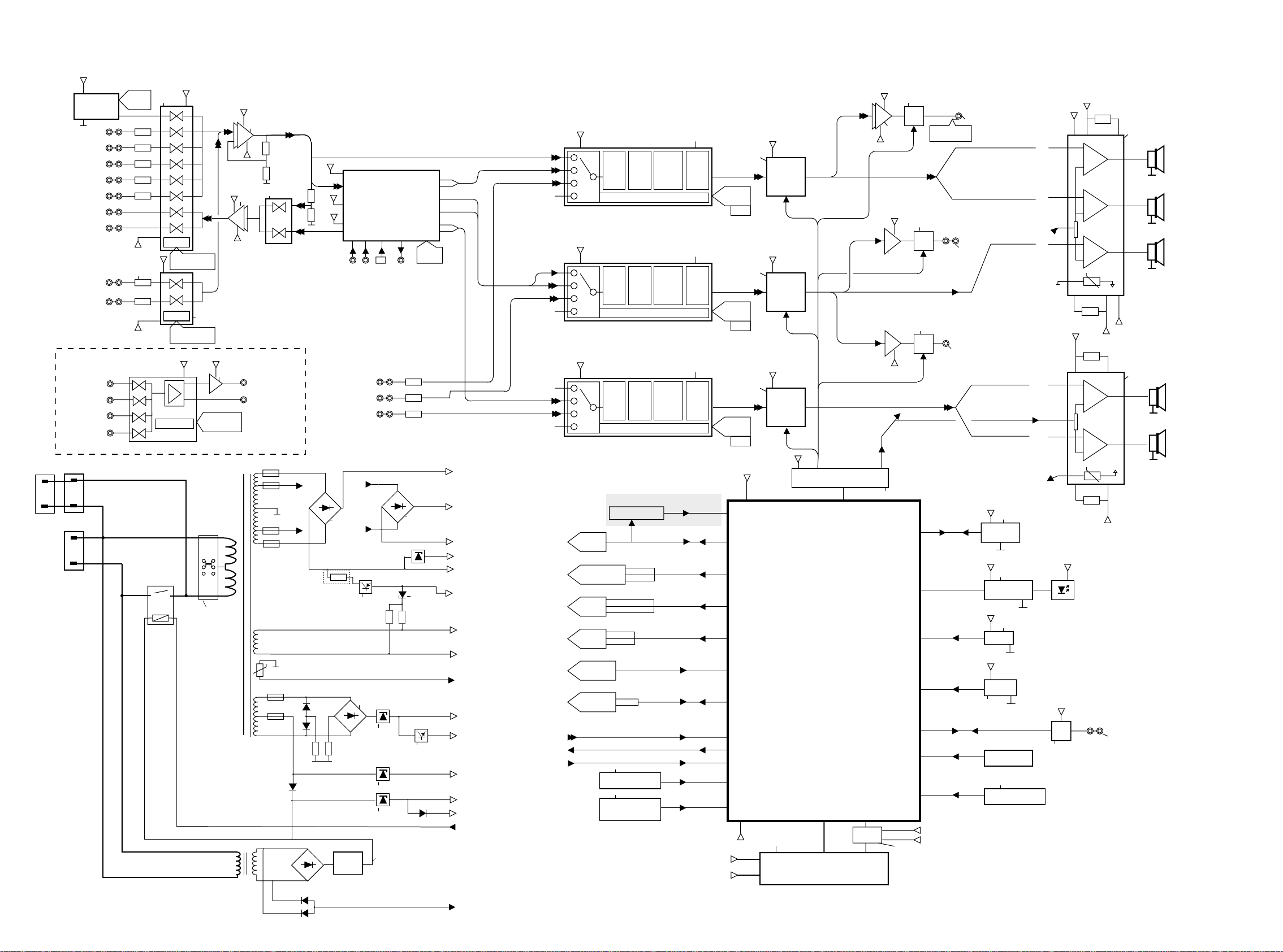
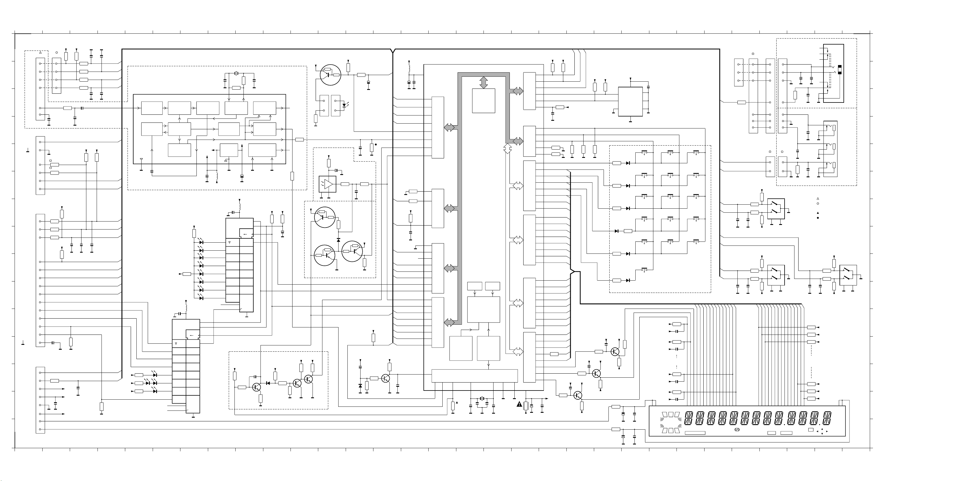
BLOCK DIAGRAM SR4000
CD
CDR/Tape
VCR
SAT
FRONT AV
CDR/Tape
VCR
PHONO
TV
VIDEO SELECTOR
DVD In
VCR In
SAT In
Front AV In
Outlet
Mains
+12
ECO5/
Tuner 95
Tuner
control
-12sel
-12sel
7803
ATT
ATT
ATT
ATT
ATT
+12sel
7571
RIAA
ATT
7501
LOGIC
Source selctor
control
LOGIC
Source selctor
control
Logic control
o o
+12sel
+5 +12
7572-b
Voltage
selector
+12
7801
7802
Video sel.
control
Only/K1B
+12
7503
-12V
7504
-12
Record path
MONITOR OUT
VCR OUT
7572-b
4-2 4-2
6257
6261
0,33E
6268
+5
L/R in
+12
-12
Downmix out
Coax in 1
6CH/DVD Input
Front L/R
C/SUB
SL/SR
6252
6253
3265
6258/6259
6262/6263
0,33E
Electric
voltage
selector
Only /K1B
MDM
DECODER
TOS
ptical in
Coax in 2
O
7257
7258
6260
6265
6267
+V
MDM
control
Coax out
ATT
ATT
ATT
6251
7907/7908
6276
7644
SUB
SL
SR
L
R
C
6649
+VH
+VL
-VL
-12
-VH
-30
F1
F2
protection 2
+12
+9
+5
+5D
+5mute
Amp Stby
MFD
Sub
C/Sub
C/Sub
+9
IN
GAIN
+9
IN
GAIN
+9
IN
GAIN
Tuner
control
Source selctor
control
MDM
control
Sofac
control
Headphone
sense
Video sel.
control
protection1,2
Amp Stby
MFD
1421
Menu navigator
1422
Source selector
encoder
BASS
VOL
MID
LOUD
TREBLE
LOGIC CONTROL
BASS
VOL
MID
LOUD
TREBLE
LOGIC CONTROL
BASS
VOL
MID
LOUD
TREBLE
LOGIC CONTROL
only /N1B
RDS DECODER
7404
RDS Info
Stereo/Clock/Data/CE
SSCE
SSCLK
SSData
Reset
SCL/SDA
Request
SDA1
SCL
SDA2
SDA
SCL
7641
SPKR
ATT
7642
SPKR
ATT
7643
SPKR
ATT
RDS Data/Clk
Sofac
control
Sofac
control
Sofac
control
-30
F1
F2
7651/7652
7657
SDA1
7653/7654
7658
SDA1
7655/7656
7658
SDA2
+5D
7415
+5mute
MUTE
+5mute
MUTE
+5mute
MUTE
+5D
Mute
control
Shift register
µP
7413
Display
Amp-ON
Current
buffer
+12
7601
-12
+12
7660-a
7660-b
-12
7411/7412
7416/7417/7418
7621/7622
Mute
7661
Mute
7662
Mute
Amp-ON
+5D
-30
Headphone
1424
Headphone
ON
Center pre-out
1525
Subwoofer pre-out
1550
CLK
DATA
protection 1
+5D
7405
Eeprom
+5D
7411/7412
Led drive
+5D
7409
Reset
+5D
IR Eye
7403
Key Matrix
1423
Volume control
L
R
Amp-ON
C
SL
Amp-ON
SR
+VL
-VP
+VL
-VP
+5
11x
+5D
RC5
7419/7421
+VH
3301
+
-
+
-
+
-
PTC
3328
3901
+
-
+
-
PTC
3915
+VP
7302
hst
-VL
-VH
+VP
7901
hst
-VL
Remote control
1541
Left
Right
Center
Surround
Left
Surround
Right
MDI 04-06-99
Page 15
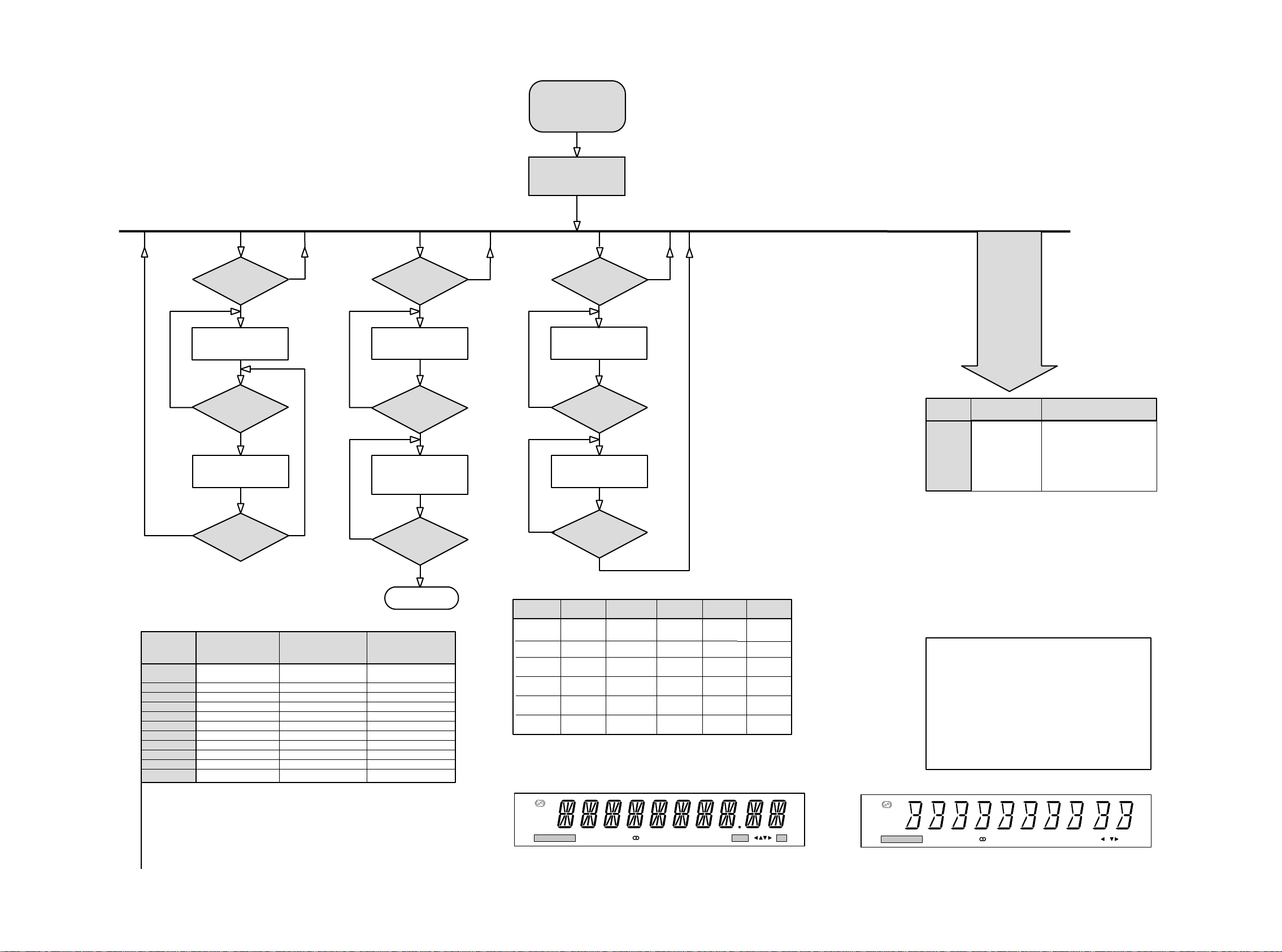
SERVICE TEST PROGRAM SR3000
5-1 5-1
To start service test
program hold
Bass & Treble depressed
while switching
the mains on
KEY
TEST
N
corresponding key number
MENU
Button pressed?
Y
Display shows"--"
any key pressed?
Y
Display shows
( see table 1)
Display shows the
following message
"S-7xx-Vzz"
TUNER
N
TEST
Button pressed?
Display shows Tuner version
N
Button pressed?
Service frequencies are
copied to the RAM (see table2)
Tuner works normally except:
Local button
TUNER
"ccc"
TUNER
N
Y
Y
DISPLAY
TEST
and switch all LEDs on
N
and switch all LEDs off
NEWS/DISPLAY
Button pressed?
Y
Display shows Fig.1
except Stby Led
NEWS/DISPLAYT
Button pressed?
Y
Display shows Fig. 2
S stands for Service T estprogram
V stands for Software Version
zz version number counted from 01 upwards
N
TEST
EEPROM
FORMAT
(RESET)
Various
other T ests
Activated with
OK Button
ACTION
Load
default data.
Display shows"NEW" for 1
second.
Caution!
All presets from the
customer will be Lost
Y
MENU
Button pressed?
N
N
Disconnect
Mains cord
Y
Service Mode left
T uner Test
Display info
Version
Preset
1
2
3
4
5
6
7
8
9
10
11
Europe
"EUR"
/N
87.5MHz
108MHz
531kHz
1602kHz
558kHz
1494kHz
153kHz
279kHz
198kHz
98MHz
----
USA
"USA"
/U
87.5MHz
108MHz
530kHz
1700kHz
560kHz
1500kHz
98MHz
----
----
----
----
This table is valid for all types of tuners.
Custormer presets will not changed after this Tuner test.
If a station is tuned then the display flag "OK" will be ON otherwise it will be OFF.
If the tuned frequency is carrying RDS information, the display flag "RDS" will be ON.
Oversea version: the tuning grid can be switched between 9kHz and 10kHz by pressing
the key "TUNER" for longer then 2 seconds. "Grid 9" or "Grid10" will be shown accordingly.
Grid 9kHz is in FM 50kHz , Grid 10kHz is in FM 100kHz
Europe version: the LW can be switched On and Off by pressing the key "TUNER" for longer
than 2 seconds. LW OFF or LW ON will be shown accordingly.
Oversea
"OSE"
/K
87.5MHz
108MHz
531kHz
1602kHz
558kHz
1494kHz
----
----
----
----
98MHz
Table 2
N
NEWS/DISPLAY
Button pressed?
Y
Key T est
2
3
4
5
6
Key
Sens
*News T/A
Prev.Exit
SetupMenu
Next
Enter/OK
Number
7
8
9
10
11
12
Key
Surr. on/off
Surr. Mode
Hall
Tuner
*Radio Text
Number
*Button Radio Text chang in Name/Frequency in /K, /U version
Button News T/A chang in Display in /K version
RDS
EON
TA
NEWS
CINEMA LINK ON
PRESET SENS
HILO HALL
LOUDNESS SMART SOUND MENU OK
Key
Loudness
Bass
Treble
#Front AV
Number
13
14
15
16
Table 1
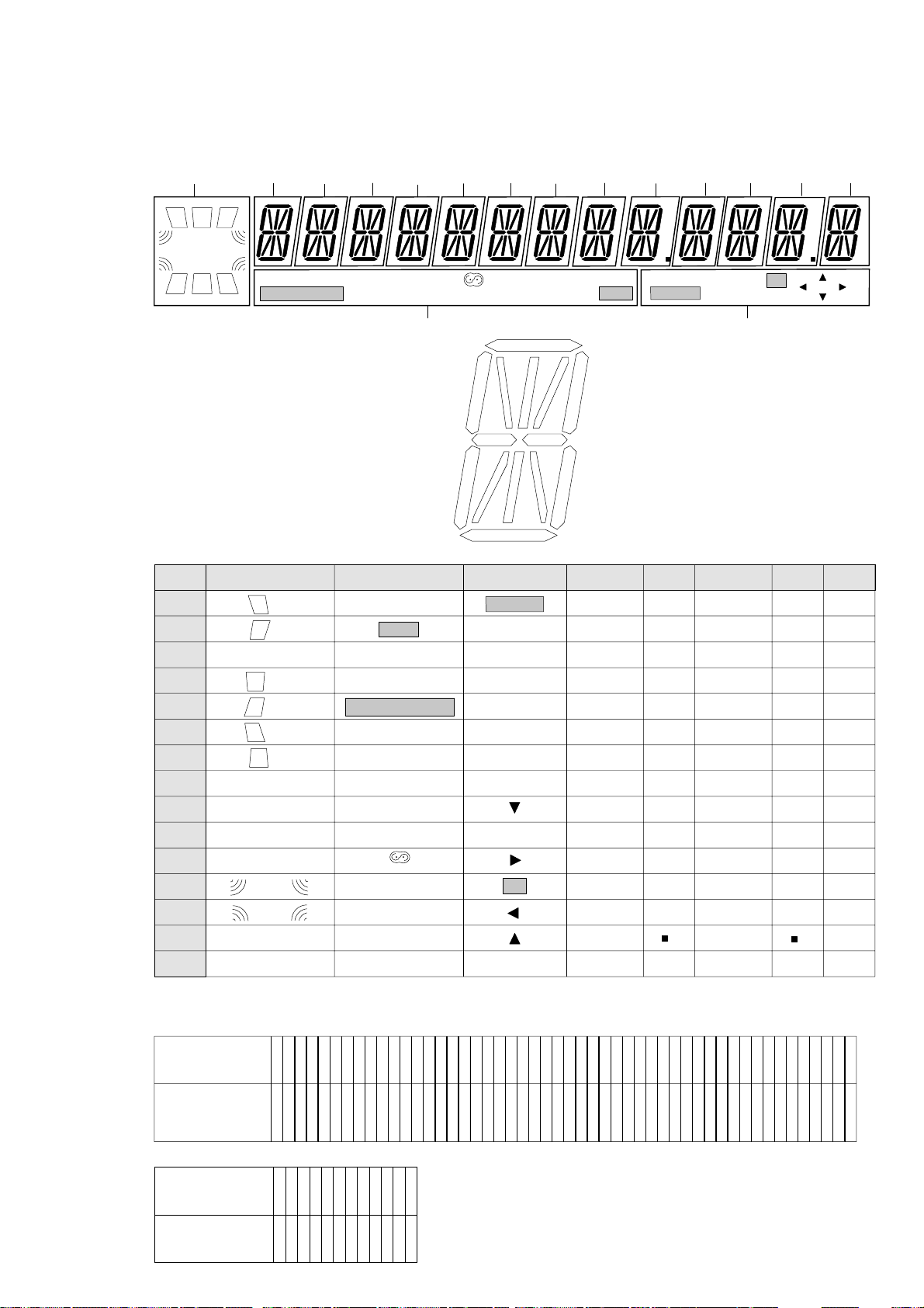
Figure 1
RDS
NEWS
CINEMA LINK ON
Default Data
Source =Tuner---Mode=stereo---Volume=10
SubwooferV ol=0---Left Volume=0---Center V olume=0
Righ Volume=0---RearL Volume=0---RearR V olume=0
Bass=0---Treble=0---Loudness=Off---Smart Sound=Personal
Center Present=Yes---Rear Present=Yes
Center Size=Small---Rear Size=Small
Front Dist = 4 meter---Rear Dist = 2 meter
For /K: AM grid is 9kHz
FM grid is 50kHz
SENS
HALL
LOUDNESS
Figure 2
Page 16
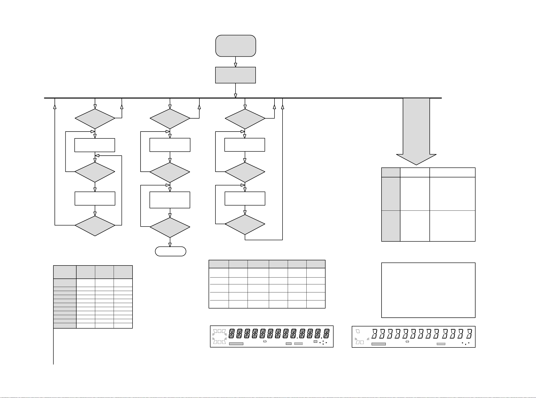
SERVICE TEST PROGRAM SR4000
5-2 5-2
To start service test
program hold
Bass & Treble depressed
while switching
the mains on
KEY
TEST
N
corresponding key number
MENU
Button pressed?
Y
Display shows"--"
any key pressed?
Y
Display shows
( see table 1)
Display shows the
following message
"S-9xx-Vzz"
TUNER
N
TEST
Display shows Tuner version
N
TUNER
Button pressed?
Y
"ccc"
TUNER
Button pressed?
Y
N
DISPLAY
TEST
and switch all LEDs on
N
NEWS/DISPLAY
Button pressed?
Y
Display shows Fig.1
except Stby Led
NEWS/DISPLAYT
Button pressed?
Y
S stands for Service T estprogram
V stands for Software Version
zz version number counted from 01 upwards
N
TEST
EEPROM
Various
other T ests
Activated with
PREV Button
ACTION
A test pattern will be
sent to the Eeprom.
"PASS" is displayed if
Service frequencies are
copied to the RAM (see table2)
Tuner works normally except:
Local button
Display shows Fig. 2
and switch all LEDs off
PREV Button
to exit
the µProcessor read
back the test pattern
corrcetly, otherwise
"ERR" will be displayed.
Y
MENU
Button pressed?
N
N
Disconnect
Mains cord
Y
Service Mode left
T uner Test
Display info
Version
Preset
1
2
3
4
5
6
7
8
9
10
11
"EUR"
/N
87.5MHz
108MHz
531kHz
1602kHz
558kHz
1494kHz
153kHz
279kHz
198kHz
98MHz
----
This table is valid for all types of tuners.
Custormer presets will not changed after this Tuner test.
If a station is tuned then the display flag "OK" will be ON otherwise it will be OFF.
If the tuned frequency is carrying RDS information, the display flag "RDS" will be ON.
Oversea version: the tuning grid can be switched between 9kHz and 10kHz by pressing
the key "TUNER" for longer then 2 seconds. "Grid 9" or "Grid10" will be shown accordingly.
Grid 9kHz is in FM 50kHz , Grid 10kHz is in FM 100kHz
Europe version: the LW can be switched On and Off by pressing the key "TUNER" for longer
than 2 seconds. LW OFF or LW ON will be shown accordingly.
Europe
USA
"USA"
/U
87.5MHz
108MHz
530kHz
1700kHz
560kHz
1500kHz
98MHz
----
----
----
----
Oversea
"OSE"
/K
87.5MHz
108MHz
531kHz
1602kHz
558kHz
1494kHz
----
----
----
----
98MHz
Table 2
N
NEWS/DISPLAY
Button pressed?
Y
Key Test
2
3
4
5
6
Key
Sens
*News T/A
Prev.Exit
Setup Menu
Next
Number
7
8
9
- 11
Key
Surr. on/off
Surr. Mode
3D Surr.
Tuner
*Radio Text
Number
*Button Radio Text change in Name/Frequency in /K, /U version
Button News T/A change in Display in /K, /U version
Button Front A/V not in FR960
LCR
DIGITAL
SURROUND
SSS
LWR
PRESET SENS HILO
CINEMA LINK ON
STEREO
EON TA NEWS
HALL LOUDNESSSMART SOUND
RDS
MATRIX
Key
Enter/OK
Loudness
Bass
Treble
*Front A/V
ANA COAX 12 OPT 12
NIGHT
DOWNMIX
Number
12
13
14
15
16
Table 1
OK
MENU
Figure 1
LC
DIGITAL
S
LWR
EEPROM
FORMAT
OK Button
Display shows"NEW" for 1
second.
Caution!
All presets from the
customer will be Lost
Default Data
Source =Tuner---Mode=stereo---Volume=10---SubwooferVol=0
LeftVolume=0---CenterVolume=0---Righ V olume=0
RaerVolume=0---RearLVolume=0---RearRVolume=0---Bass=0
Treble=0---Loudness=Off---Smart Sound=Personal---Center
Present=Yes---RearPresent=Yes---FrontSize=Large
Subwooferpresent=Yes--- CenterSize=Small---RearSize=Small
EffectIncr3D=100--DigInputCoax1=DVD
L/RDist=4meter---CenterDist=3meter---RearDist=2meter
For USA /17:
L/RDist=13Feet---CenterDist=10Feet---RearDist=7Feet.
For /01: AM grid is 9kHz
: FM grid is 50kHz
SENS
CINEMA LINK ON
STEREO
RDS
NEWS
ANA 1 OPT 2
MATRIX
HALL LOUDNESS
DOWNMIX
Figure 2
Page 17
6-1
FRONT BOARD
TABLE OF CONTENTS
FTD Display pin connections................................... 6-2
Headphone & Led board layout ............................. 6-4
Circuit diagram ........................................................ 6-5
Component layout ................................................... 6-7
Partslist .................................................................... 6-8
Page 18
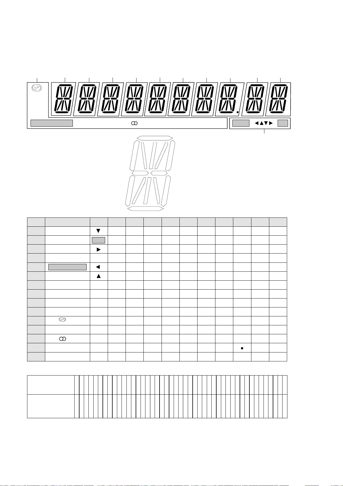
FTD DISPLAY PIN CONNECTIONS SR3000
6-2
RDS
EON
TA
NEWS
CINEMA LINK
1G
P1
LOUDNESS
P2
P3
P4
P5
P6
P7
P8
P9
P10
P11
P12
LO
CINEMA LINK
EON
HALL
HI
NEWS
PRESET
RDS
SMART SOUND
P13
P14
P15
TA
SENS
3G1G
-
-
4G
PRESET SENS
2G 3G
MENU
OK
-
-
-
-
-
-
-
-
-
HILO HALL
h
f
g
e
d
4G
a
j p
h
k
b
f
m
g
c
e
r
n
d
-
-
a
j p
h
k
b
f
m
g
c
e
r
n
d
-
-
9G
8G
a
j p
h
k
b
f
m
g
c
e
r
n
d
-
-
9G
a
j p
h
k
b
f
m
g
c
e
r
n
d
-
-
10G
11G
10G
a
j p
h
k
b
f
m
g
c
e
r
n
d
-
c
b
6G
a
j p
h
k
b
f
m
g
c
e
r
n
d
-
-
8G
7G
a
j p
h
k
b
f
m
g
c
e
r
n
d
-
-
7G6G5G
LOUDNESS SMART SOUND MENU OK
a
j
k
m
p
nr
5G
a
j p
h
k
b
f
m
g
c
e
r
n
d
-
-
2G
11G
a
j p
h
k
b
f
m
g
c
e
r
n
d
-
-
12G
12G
a
j p
h
k
b
f
m
g
c
e
r
n
d
-
-
Pin Connection
Pin numbers
4 4 4 4 4 4 3 3 3 3 3 3 3 3 3 3 2 2 2 2 2 2 2 2 2 2 1 1 1 1 1 1 1 1 1 1
5 4 3 2 1 0 9 8 7 6 5 4 3 2 1 0 9 8 7 6 5 4 3 2 1 0 9 8 7 6 5 4 3 2 1 0 9 8 7 6 5 4 3 2 1
Connection
Note: NC -------------- No connection
NP -------------- No pin
FI , F2 ---------- Filament
1G ~ 12G ------ Grid
F F N N N N N N
P P C C C C
2 2
1 2 3 4 5 6 7 8 9 0 1 2
1 1 1
G G G G G G G G G G G G
N N N N N N 1 1 1 1 1 1
C C C C C C
P P P P P P
5 4 3 2 1 0 9 8 7 6 5 4 3 2 1 P P1 1
P P P P P P P P P N N F F
Page 19
12G
11G
10G
9G
8G
7G
6G
5G
4G
1G
2G
a
b
c
d
e
f
g
h
j
k
m
nr
p
RDS
EON
TA
NEWS
CINEMA LINK
PRESET
SENS
LO
HALL
LOUDNESS
SMART SOUND
HI
P1
P2
P3
P4
P5
P6
P7
P8
P9
P10
P11
P12
P13
P14
P15
1G
2G
a
j p
h
k
b
f
m
g
c
e
r
n
d
-
-
12G
a
j p
h
k
b
f
m
g
c
e
r
n
d
-
16G
a
j p
h
k
b
f
m
g
c
e
r
n
d
-
-
FTD DISPLAY PIN CONNECTIONS SR4000
5 4 4 4 4 4 4 4 4 4 3 3 3 3 3 3 3 3 3 3 2 2 2 2 2 2 2 2 2 2 1 1 1 1 1 1 1 1 1 1
0 9 8 7 6 5 4 3 2 1 0 9 8 7 6 5 4 3 2 1 0 9 8 7 6 5 4 3 2 1 0 9 8 7 6 5 4 3 2 1 0 9 8 7 6 5 4 3 2 1
Pin numbers
1 2 3 4 5 6 7 8 9 0
1 2 3 4 5 6
N N N N N N
1 1 1 1 1 1
P P P P P P P P P
1 1 1 1 1 1 1
P P P P P P
G G G G G G G G G G G G
G G G G C C C C C C
Connection
Pin Connection
Note: FI , F2 --------- Filament
NC -------------- No connection
NP -------------- No pin
1G ~ 16G ----- Grid
NIGHT
DOWNMIX
DIGITAL
SURROUND
LCR
SSS
RDS
EON TA NEWS
PRESET SENS HILO
HALL LOUDNESSSMART SOUND
MENU
OK
LWR
CINEMA LINK
STEREO
ANA COAX 12 OPT 12
MATRIX
3G
16G
15G
14G
13G
STEREO
MATRIX
ANA
DOWNMIX
COAX
OPT
MENU
OK
-
NIGHT
1
(coax)
2
(coax)
1
(opt)
2
(opt)
3G
4G~11G
(1)
a
j p
h
k
b
f
m
g
c
e
r
n
d
-
-
13G ,14G
15G
a
j p
h
k
b
f
m
g
c
e
r
n
d
-
(2)
L
R
C
S
L
S
R
( )
S
W
S
L
S
R
(L)
(R)
DIGITAL
SURROUND
( )
(1)
(2)
(C)
5 4 3 2 1 0 9 8 7 6 5 4 3 2 1
N N N N N N N N N N N F F
C C C C C C C C C P P
1 1
Pin numbers
Connection
6 6 6 5 5 5 5 5 5 5 5 5
2 1 0 9 8 7 6 5 4 3 2 1
P P C C C C C C C C
F F N N N N N N N N N N
2 2
6-3
Page 20
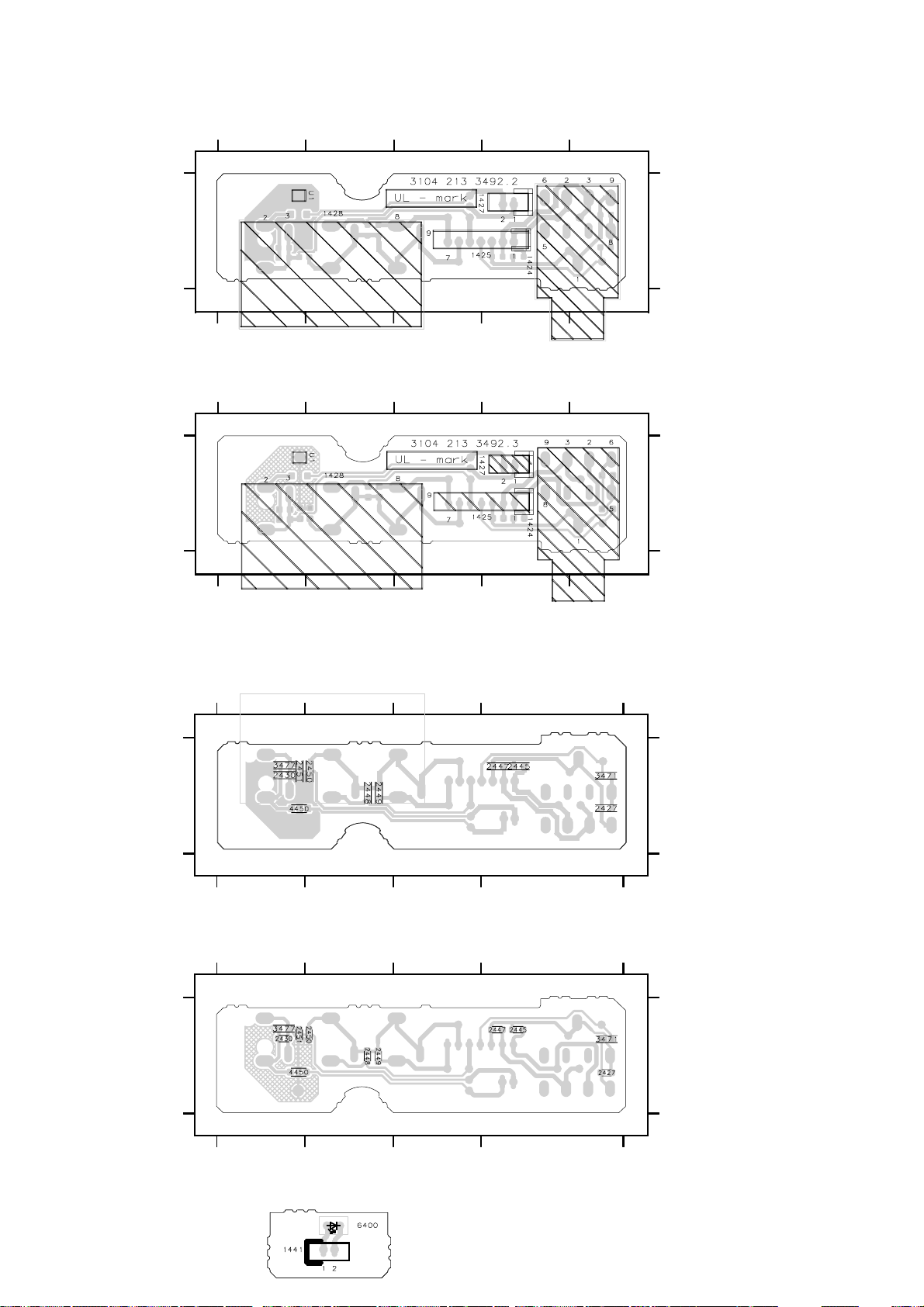
HEADPHONE BOARD - COMPONENT VIEW
SR3000
D C B A
11
D C B A
SR4000
D C B A
11
6-4
U1 C1
1424 A1
1425 A1
1427 A1
1428 C1
U1 C1
1424 A1
1425 A1
1427 A1
1428 C1
D C B A
HEADPHONE BOARD - COPPER SIDE VIEW
SR3000
D C B A
11
D C B A
SR4000
D C B A
11
2427 A1
2430 D1
2445 A1
2447 A1
2448 C1
2449 C1
2450 C1
2451 D1
3471 A1
3477 D1
4450 D1
2427 A1
2430 D1
2445 A1
2447 A1
2448 C1
2449 C1
2450 C1
2451 D1
3471 A1
3477 D1
4450 D1
D C B A
LED BOARD - COMPONENT VIEW
Page 21
6-56-56-5
1
2
FRONT PART SR3000
+5D
1401 1433
6
stereo
5
tu clk
4
tu de
3
tu en
From Tuner
2
tu rds
1
tu gnd
From
D
Tuner
1402
6
P50
5
3
V sda
4
V scl
1
V sig
2
V gnd
To 1560
P50 Board &
Video Selector
1410
sofac scl
sofac1 sda1
sofac2 sda2
ss ce
dpl clk
ss data
ss clk
amp prot
dd req
amp s on
amp lr on
amp mute lr
amp mute c s
FRONT PART FR735 - FR755
3104 217 05790 / 05850 / 05860 / 05870 / 05880
4
5
6
1
7
3
2
11
15
8
9
12
13
10
To/From
Volume Control Part
1426
amp stby
amp pd
+5D
+5
gndd
–30
f2
f1
1
2
4
3
5
6
8
7
From 1257
Monoboard Supply Part
+5
2444
D
1
2410
22n
1434
3501
470E
3500
470E
3493
470E
3494
470E
3495
470E
10k
22n
3414
$
3407
1k
3403 3405
6k8
4
3
2
1
1k
1
2
D
+5D
3406
10k
+5
3412
10k
D
+5D
+5
2461
22n
D
–30
2
3
+5D
22k
3499
470E
3498
470E
3497
470E
3496
470E
24023413
330p
2407
470p
D
+5D +5D
3402 3401
10k
2435 2436 2437
220p
220pD220p
DD
6411
1N4148
3394
22k
D
2404
1n
D
3
D
2441 2440
220pD220p
2439 2438
220pD220p
D
10k
sofac1 sda1
sofac2 sda2
3393
22k
D
4
stereo
tu clk
tu de
tu en
V sig
V gnd
sofac scl
ss ce
dpl clk
ss data
ss clk
amp prot
dd req
amp stby
amp pd
4
P50
5
SAA6579T
COMPARATOR
Vssd
11
D
Only in sets with RDS
3447
+5
330E
3427
+5
150E
5
7404
ANTI
ALIASING
FILTER
CLOCKED
6421
LTL-1CHPE
6
57 kHz
BANDPASS
(8th ORDER)
COSTAS LOOP
VARIABLE AND
FIXED DIVIDER
CLOCK
REGENERATION
AND SYNC
Cin
2403
560p
D
4
3
5
6
7
**
6410
14
DVD
6401
13
SURR
12
11
9
10
6
2417
22n
7
RECON-
STRUCTION
SCout
87
+5D
5401
2
2µ
7412
HEF4094BT16
1
C2
15
EN3
SRG8
3
C1/
2D
2
1D
8
D
7
FILTER
Vpi
Vddd
12
D
22n
+5D
100k
3454
0E
8
DD
13
OscI14OscO
OSCILLATOR
DIVIDER
BIPHASE
SYMBOL
DECODER
REFERENCE
VOLTAGE
Vdda
Vssa
5
6
D
54002408 2409
2µ2
+5
3449
2428
7µ4
D
1400
AT-5I
4M332
3411
220k
AND
9
3410
2k2
TEST LOGIC
AND OUTPUT
SELECTOR SWITCH
Vref
Mode
3
9
2µ2
D
+5D
3451
10k
24432442
47p47p
QUALITY
BIT
GENERATOR
DIFFERENTIAL
DECODER
Test
10
DD
P50
+5D
2411
3433
10k
220p
3437
100k
7406
BC847B
8
9
+5D
6402 3438
1N4148
3440
220E
D
10
27k
10
QualMux
RDDA
RDCL
T57
3428
14
2
16
15
BC847B
33k
11
+5D
3404
330E
D
3422
10k
3416
10K
+5D
47k
+5D
+5D
3429 3430
22k
7408
BC847B
D
22k
D
7407
3441
22k
D
Only in sets with P50 function
11
7402
PDTA144ET
47k
1440 1441
212
+5D
7403
43
D
47k
7421
PDTA144ET
BAS216
47k
7419
PDTC144ET
47k
12
47E
2
6424
12
3400
D
47k
2400
100
1
6400
µ
1
3487
10k
D
+5D
3392
22k
D
3409
1k
47k
7422
PDTA144ET
1N4148
3391
RC5
47k
6403
13
1k
3415
0E
2401
1n
D
+5D
3486
47k
D
+5D +5D
RESET
2434
220n
100k
13
D
DDDD
2456
47
3442
22k
3439
µ
3455
D
+5
10k
3408
10k
BC847B
14
amp stby
P50
dd req
7409
14
3431
10k
2420
µ
100
stereo
tu clk
tu de
tu en
D
amp prot
hp ON
nav 1
nav 2
v cont 1
v cont 2
dpl clk
sofac2 sda2
sofac1 sda1
sofac scl
ss ce
s sel 1
s sel 2
reset
2414
22n
+5D
+5D
5403
3483
100k
3426
1k
10k
D
µ22
D
15
3421
2413
22n
15
2458
22n
DD
TMP87CS71F
33
Vdd
4
6
7
8
5
1
2
3
74
73
67
32
31
27
30
29
28
25
26
17
24
23
22
21
20
19
18
12
7415
I/O
I/O
P4
I/O
P7
I/O
P3
P20
16
16
P1
P21
10
16
17
RAM ROM
TIMER/
CLOCK/TIMER/SYSTEM
CONTROLLER
P22
11
100k
D
3476
2416
X in X out
13
22p
17
6-BIT A/D
CONVERTER
8-BIT
CPU
INTERRUPT
CONTROLLERCOUNTERS
1403
CST
D
18
Test
14
2415
22p
DD
Vss
915 66
D
D
18
3432
19
I/O
P5
I/O
P4
I/O
P9
I/O
P8
I/O
P7
I/O
P6
Vkk
4E7
–30
19
77
76
80
79
78
75
70
69
68
71
72
65
64
63
62
61
60
59
58
57
56
55
54
53
52
51
50
49
48
47
46
45
44
43
42
41
40
39
38
37
36
35
34
2412 2457
µ
47
D
D
20
10k+510k
3491
100k
100k
3475
22n
20
+5
3419 3420
3472
1k
2454
22n
D
D
D
S14
S13
S12
S11
S10
S9
S8
S7
S6
S5
S4
S3
S2
S1
S0
G15
G14
G13
G12
G11
G10
G9
G8
G7
G6
G5
+Vkk
21
ss clk
ss data
amp pd
+5
+5
3434 3435 3436
22k
22k
DDD
+5D +5D
2433
100p
3396
1k
7417
BC847B
100k
–30V
0E 4E7
3473
0E
21
22
+5
34183417
10k
10k
D
22k
1N4148
3490
0E
3482
34883474
24592455
22n
µ
47
DD
3489
4E7
2460
2429
22n
µ
47
D
D
22
7405
M24C08
5
SDA
6
SCL
7
WC_
3443
6404
330E
1N4148
3444 6405
330E
1N4148
3452 6406
330E
1N4148
34536414
330E
3457 6419
330E
1N4148
3458 6420
330E
1N4148
23
+5D
8
Vcc
1
E0
2
E1
3
E2
Vss
4
D
1404 1405 1406
BASS
1407 1408 1409
AM/FM
1411 1412 1413
SENS TEXT NEWS T/A
1414 1415 1416
MENU ENTER HALL
1417
CINEMA LINK SURR SURR MODE
1420
FRONT A/V
3755
–Vkk
33k
2467
–Vkk
100p
3756
–Vkk
33k
2468
–Vkk
100p
3765
–Vkk
33k
2477
–Vkk
100p
3766
–Vkk
33k
2478
–Vkk
100p
RDS
EON
TA
NEWS
CINEMA LINK
23
24
2405
22n
D
LOUDNESS TREB
PREV
1418 1419
ON/OFF
G4 G15 S0 S14
HILOSENSPRESET
24
25
NEXT
25
7414
12-MT-74GK
2436394041 3738 30333534 32 31 2729 28 2625 132322 2021 19 1718 16 1415 7101112 98 65 214445
LOUDNESSHALL
26
hp l
hp r
hp gnd
To/From 1601
hp ON
V sig
V gnd
SELECTOR
s sel 1
s sel 2
nav 1
nav 2
v cont 1
v cont 2
SMART SOUND
26
27
$
1
2
3
Volume
Control part
3424
1k
av l
av gnd
av r
To/From 1515
Volume Control Part
Source Slector Part
SOURCE
2424 2423
DD
VOLUME
22nD22n
D
MENU
27
14371439
22n22n
24252426
+
3466
220E
3469
220E
3467
220E
3470
220E
28
HEADPHONE
1436 1425
11
1
22
2
33
3
44
55
4
66
5
77
6
1427
1435
22
11
+5D
1422
3461
EC16
10k
1
2
MT1
MT2
10k
3462
+5D
+5D
3463
10k
10k
3464
+5D
3767
3768
3769
3779
3780
3781
OK
5
4
D
EC16
1
2
MT2
MT1
5
4
D
–Vkk
33k
–Vkk
33k
–Vkk
33k
–Vkk
33k
–Vkk
33k
–Vkk
33k
28
29
HP HP
HP
3471
1k
HP
A
A
2449
1n
A
3477
68E
VV V
2451 2450
VAA
1n
3
D
D
NAVIGATORCONTROL
3
D
D
Only in sets with RDS
Not in sets with RDS
Only in FR755
Only in sets with 6 CH/DVD input (FR755)
*
Not in sets with P50 function
Not in sets with RDS
29
6
5
4
2
3
24452447
7
4n74n7
8
9
2427
1
1n
HP
FRONT AV
5
6
2448
4
1n
A
8
9
7
A
2
3
2430
1
220p
V
V
3465
220E
3468
220E
2422 2421
22n22n
DD
30
1428
30
1424
1n
+5D
+5D
Audio Left In
Audio Right In
Video In
3459
10k
1
2
MT1
10k
3460
31
14211423
EC16
3
D
MT2
4
5
D
D
LEU0167
9912
AA
BB
CC
DD
EE
FF
GG
HH
II
JJ
KK
LL
MM
NN
OO
1400 B8
1401 A1
1402 D1
1403 N17
1404 E23
1405 E24
1406 E25
1407 F23
1408 F24
1409 F25
1410 G1
1411 F23
1412 F24
1413 F25
1414 G23
1415 G24
1416 G25
1417 H23
1418 H24
1419 H25
1420 I23
1421 I31
1422 G28
1423 I28
1424 A30
1425 A28
1426 M1
1427 E28
1428 D30
1433 A2
1434 D2
1435 E28
1436 A28
1437 A27
1439 A27
1440 C12
1441 C12
2400 E12
2401 F13
2402 C3
2403 E6
2404 M3
2405 B24
2407 D3
2408 F8
2409 F9
2410 D2
2411 M9
2412 N19
2413 H15
2414 M14
2415 N18
2416 N17
2417 K6
2420 B15
2421 J30
2422 J29
2423 H27
2424 H27
2425 J27
2426 J27
2427 C29
2428 K8
2429 O22
2430 F29
2433 L21
2434 M13
2435 H3
2436 H3
2437 H3
2438 C4
2439 C3
2440 A4
2441 A3
2442 B8
2443 B9
2444 L2
2445 B29
2447 B29
2448 D29
2449 E29
2450 F30
2451 F29
2454 C20
2455 N22
2456 B13
2457 N20
2458 B15
2459 N22
2460 O22
2461 N2
2467 K23
2468 L23
2477 M23
2478 N23
3391 B13
3392 B13
3393 N4
3394 L3
3396 L21
3400 E12
3401 E4
3402 E3
3403 A2
3404 D11
3405 A3
3406 G2
3407 I2
3408 L14
3409 F12
3410 B9
3411 B8
3412 I2
3413 C2
3414 M2
3415 F13
3416 F11
3417 B22
3418 B22
3419 B20
3420 B20
3421 G15
3422 D11
3424 C27
3426 F15
3427 M5
3428 M10
3429 M11
3430 M11
3431 M14
3432 N19
3433 M9
3434 E21
3435 E21
3436 E22
3437 M9
3438 M10
3439 M13
3440 N10
3441 N11
3442 M13
3443 E22
3444 F22
3447 M5
3449 J8
3451 K9
3452 G22
3453 H23
3454 L8
3455 E13
3457 H22
3458 I22
3459 I30
3460 J30
3461 G28
3462 H28
3463 I28
3464 J28
3465 I30
3466 G27
3467 I27
3468 J30
3469 G27
3470 J27
3471 C29
3472 C20
3473 O21
3474 N21
3475 E20
3476 N16
3477 F29
3482 M22
3483 F15
3486 I13
3487 G12
3488 N22
3489 O22
3490 L22
3491 E20
3493 G2
3494 H2
3495 H2
3496 B3
3497 B3
3498 B3
3499 A3
3500 F2
3501 E2
3755 K23
3756 L23
3765 M23
3766 M23
3767 K28
3768 K28
3769 L28
3779 M28
3780 M28
3781 N28
5400 F8
5401 J7
5403 B15
6400 C12
6401 M6
6402 M10
6403 M13
6404 E23
6405 F23
6406 G23
6410 M6
6411 I3
6414 H22
6419 H23
6420 I23
6421 M5
6424 H12
7402 A12
7403 F12
7404 C5
7405 B22
7406 N9
7407 M11
7408 M11
7409 M14
7412 K7
7414 N25
7415 A16
7417 L21
7419 I12
7421 H12
7422 I13
31
Page 22
6-66-66-6
1
2
FRONT PART SR4000
+5D
14331401
6k8
4
6
stereo
5
tu clk
tu de
tu en
tu rds
tu gnd
From
Tuner
1402
P50
V sda
V scl
V sig
V gnd
To 1560
P50 Board &
Video Selector
1410
sofac scl
sofac1 sda1
sofac2 sda2
ss ce
ss clk
ss data
amp prot
To/From
Volume Control Part
1426
amp stby
amp pd
+5D
+5
gndd
–30
f2
f1
From
Power Supply
15
14
12
13
10
dd req
dd reset
amp s on
amp lr on
amp mute lr
amp mute
cs sub
FRONT PART FR960 - FR970
3104 217 05890 / 05900 / 05920 / 05930
1
3
4
2
3
1
From Tuner
D
D
2444
22n
D
2410
22n
470E
3500
470E
3493
470E
3494
470E
3495
470E
3414
3501
1k
3413 2402
+5D
3406
10k
+5
3407
10k
D
+5D
+5
2461
22n
D
–30
1k
2
1
6
5
3
4
1
2
4
5
6
1
2
3
11
8
9
1
2
4
3
5
6
8
7
2
3
+5D
34053403
22k
3499
470E
3498
470E
3497
470E
3496
470E
330p
2407
470p
D
+5D +5D
220p
220pD220p
DD
3394
22k
D
2404
1n
D
3
10k
D
24402441
220pD220p
24382439
220pD220p
D
34013402
10k
sofac1 sda1
sofac2 sda2
243724362435
3393
22k
D
4
stereo
tu clk
tu de
tu en
P50
V sig
V gnd
sofac scl
ss ce
ss clk
ss data
amp prot
dd req
amp stby
amp pd
4
5
SAA6579T
COMPARATOR
Vssd
11
D
Only in sets with RDS
3447
+5
330E
3427
+5
150E
3446
+5
330E
5
7404
ANTI
ALIASING
FILTER
CLOCKED
6421
LTL-1CHPE
Cin
2403
560p
6410
DVD
6401
SURR
6412
HALL
**
6
57 kHz
BANDPASS
(8th ORDER)
COSTAS LOOP
VARIABLE AND
FIXED DIVIDER
CLOCK
REGENERATION
AND SYNC
+5
2417
D
22n
4
3
5
6
7
14
13
12
11
9
10
6
7
RECON-
STRUCTION
FILTER
SCout
87
+5
3448
330E
3445
330E
+5D
LTL-1CHPE
5401
2
2µ
7412
HEF4094BT16
1
C2
15
EN3
SRG8
3
C1/
2D
2
1D
8
D
7
8
2442 2443
DD
13
OscI14OscO
OSCILLATOR
DIVIDER
BIPHASE
SYMBOL
DECODER
REFERENCE
Vpi
VOLTAGE
Vddd
Vdda
12
22n
D
6409
PHONO
6408
TUNER
6407
CD
6418
CDR/TAPE
6415
3D-SURR
6416
SAT
6413
VCR
6417
TV
Vssa
5
6
D
2µ2
+5
2419
D HEF4094BT
22n
4
3
5
6
7
14
13
12
11
9
10
1400
AT-5I
4M332
3411
220k
AND
+5D
5402
16
2D 1D
9
3410
2k2
AND OUTPUT
SELECTOR SWITCH
Vref
Mode
3
9
24092408 5400
2µ2
D
µ22
7411
C2
EN3
SRG8
C1/
8
D
P50
+5D
2411
3433
10k
220p
3437
100k
7406
BC847B
8
9
47p47p
QUALITY
BIT
GENERATOR
DIFFERENTIAL
DECODER
TEST LOGIC
1
15
3
2
1N4148
3440
47E
D
+5D
10
QualMux
RDDA
RDCL
T57
Test
10
DD
+5D
34493451
10k
100k
2428
D
+5D
3428
27k
34386402
220k
10
11
14
2
3422
16
10k
15
3416
10K
+5D
7µ4
+5D
22k
7407
BC847B
7408
BC847B
3441
82k
D
D
Only in sets with P50 function
11
+5D
22k
+5D
3404
330E
D
PDTA144ET
47k
PDTC144ET
34303429
D
7402
PDTA144ET
47k
212
+5D
7403
43
D
47k
7421
BAS216
47k
7419
12
47k
14411440
1
RC5
3400
47E
2400
µ
100
2
1
D
47k
10k
6424
D
12
+5D
6400
D
3409
1k
3487
47k
PDTA144ET
3392
22k
7422
6403
1N4148
13
3391
1k
3423
2401
1n
D
47k
+5D +5D
2462
1n
D
3415
+5D
2434
220n
0E
47k
2456
µ
47
D
3455
22k
D
3486
D
+5
10k
RESET
3439
10k
3442
100k
DDDD
amp stby
3408
BC847B
13
7409
dd req
P50
14
3431
10k
14
2420
µ
100
stereo
tu clk
tu de
tu en
D
amp prot
hp on
nav 1
nav 2
v cont 1
v cont 2
sofac2 sda2
sofac1 sda1
sofac scl
ss ce
s sel 1
s sel 2
reset
2414
22n
+5D
+5D
5403
3483
100k
3426
10k
15
µ22
33
2458
22n
DD
4
6
7
8
5
1
2
3
74
73
1k
3421
67
2413
22n
D
32
D
31
27
30
29
28
25
26
17
24
23
22
21
20
19
18
12
15
7415
TMP87CS71F
Vdd
I/O
I/O
P4
I/O
I/O
P20
16
16
P1
P7
P3
P21
10
16
17
RAM ROM
TIMER/
CLOCK/TIMER/SYSTEM
CONTROLLER
P22
11
100k
3476
D
X in X out
13
2416
22p
17
6-BIT A/D
CONVERTER
8-BIT
CPU
INTERRUPT
CONTROLLERCOUNTERS
1403
8Mc
CST
D
18
Test
14
91566
D
2415
22p
DD
18
Vss
D
3432
19
I/O
P5
I/O
P4
I/O
P9
I/O
P8
I/O
P7
I/O
P6
Vkk
4E7
D
–30
19
20
10k+510k
77
76
80
79
78
3472
75
1k
2454
22n
D
70
69
68
3491
71
100k
72
100k
3475
65
64
S14
63
S13
62
S12
61
S11
60
S10
59
S9
58
S8
57
S7
56
S6
55
S5
54
S4
53
S3
52
S2
51
S1
50
S0
49
G15
G14
48
G13
47
G12
46
G11
45
G10
44
G9
43
G8
42
G7
41
G6
40
G5
39
3395
G4
38
0E
G3
37
36
35
34
3479
–Vkk
24572412
22n
µ
47
D
20
+5
ss data
34203419
+5
22k
D
DDD
D
+5D +5D
2431
10p
1k
7418
BC847B
–30
21
ss clk
3481
1k
21
amp pd
22k
+5D +5D
7416
BC847B
3478
100k
+5
3417 3418
10k
343634353434
22k
3484
2432
10p
–30
+5
+5D +5D
1k
3480
100k
22
10k
D
2433
100p
7417
BC847B
22
7405
M24C08
5
SDA
6
SCL
7
WC_
3443
330E
330E
330E
6414 3453
1N4148
330E
330E
3482
100k
–30
3474
0E
3473
0E
23
+5D
8
Vcc
1
E0
2
E1
3
E2
Vss
4
D
BASS
6404
1N4148
AM/FM
64053444
1N4148
SENS TEXT NEWS T/A
64063452
1N4148
MENU ENTER HALL
330E
1417
CINEMA SURR MODE
64193457
1N4148
1420
FRONT A/V
64203458
1N4148
0E
3485
2455 2459
22n
µ
47
D
D
2429
2460
22n
µ
47
DD
23
24
2405
22n
D
LOUDNESS TREB
–Vkk
–Vkk
–Vkk
–Vkk
–Vkk
–Vkk
–Vkk
–Vkk
6261 5857565554535251504948474645444342414039383736353433323130292827262524232221201918171615141312111098765 21
L
SLSS
24
PREV
ON/OFF
3751
33k
2463
100p
3752
33k
2464
100p
to
to
3765
33k
2477
100p
3766
33k
2478
100p
RC
DIGITAL
SURROUND
WR
25
26
27
28
HEADPHONE
$
1439 1437
1
hp l
hp r
hp gnd
To/From 1601
Volume
Control part
hp on
140614051404
V sig
140914081407
NEXT
141314121411
141614151414
14191418
V gnd
SOURCE
SELECTOR
s sel 1
s sel 2
nav 1
nav 2
VOLUME
v cont 1
v cont 2
G0 G15 S0 S14
24762465
37643753
PRESET SENS HILO
CINEMA LINK
25
STEREO
SMART SOUND
26
RDS
1
2
2
3
3
3424
1k
4
av l
5
av gnd
6
av r
To/From 1515
Volume Control Part
+
Source Slector Part
3466
220E
3469
220E
24232424
22n22n
DD
3467
220E
3470
220E
2426 2425
22nD22n
D
7413
16-MT-95GK
TA NEWS
HALL MATRIX
27
+5D
+5D
+5D
+5D
14251436
11
22
33
44
55
66
77
1435
22
11
3461
10k
1
2
MT1
10k
4
3462
D
3463
10k
1
2
MT1
10k
4
3464
D
ANA OK
NIGHT
HP
1k
A
1427
VV V
1422
EC16
3
D
MT2
5
D
1423 1421
EC16
3
D
MT2
5
D
OPT 12EON
COAX 12
DOWNMIX
28
29
2447 2445
HP HP
3471
HP
2449
1n
A
3477
68E
NAVIGATORCONTROL
LOUDNESS
29
6
5
4
2
3
7
4n74n7
8
9
2427
1
1n
HP
5
6
2448
4
1n
A
A
8
9
7
A
2
3
2430
1
220p
V
V
Only in sets with RDS
Not in sets with RDS
Only in sets with DVD input
*
Not in sets with P50 function
Not in sets with RDS
Not in FR970$
3465
220E
3468
220E
24212422
22n22n
DD
3767
–Vkk
33k
3768
–Vkk
33k
3769
–Vkk
33k
3770
to
3778
3779
–Vkk
33k
3780
–Vkk
33k
3781
–Vkk
33k
MENU
30
1424
FRONT AV
1428
Audio Left In
Audio Right In
Video In
+5D
3459
EC16
10k
1
2
MT1
10k
4
3460
D
+5D
30
MT2
31
5
D
LEU0155
31
1400 B8
1401 A1
1402 D1
1403 N17
AA
1404 E23
1405 E24
1406 E25
1407 F23
1408 F24
1409 F25
1410 G1
1411 F23
BB
1412 F24
1413 F25
1414 G23
1415 G24
1416 G25
1417 H23
1418 H24
1419 H25
1420 I23
CC
1421 I31
1422 F28
1423 I28
1424 A30
1425 A28
1426 M1
1427 E28
1428 D30
DD
1433 A2
1435 E28
1436 A28
1437 A27
1439 A27
1440 C12
1441 C12
2400 E12
EE
2401 F13
2402 C3
2403 E6
2404 M3
2405 B24
2407 D3
2408 F8
2409 F9
FF
2410 D2
2411 M9
2412 N19
2413 H15
2414 M14
2415 N18
2416 N17
2417 K6
GG
2419 G8
2420 B15
2421 J30
2422 J29
2423 G27
2424 G27
2425 J27
2426 J27
HH
2427 C29
2428 H10
2429 O23
2430 E29
2431 M21
2432 M21
2433 L22
2434 M13
II
2435 H3
JJ
KK
LL
MM
NN
OO
2436 H3
2437 H3
2438 C4
2439 C3
2440 A4
2441 A3
2442 B8
2443 B9
2444 L2
2445 B29
2447 B29
2448 D29
2449 E29
2454 C20
2455 N23
2456 B13
2457 N20
2458 B15
2459 N23
2460 O23
2461 N2
2462 E13
2463 K24
2464 L24
2465 L24
2476 L25
2477 M24
2478 N24
3391 B13
3392 B13
3393 N4
3394 L3
3395 L20
3400 E12
3401 E4
3402 E3
3403 A2
3404 D12
3405 A3
3406 G2
3407 I2
3408 L14
3409 F12
3410 B9
3411 B8
3413 C2
3414 M2
3415 F13
3416 F11
3417 B22
3418 B22
3
D
9919
3419 B20
3420 B20
3421 G15
3422 D11
3423 B13
3424 C27
3426 F15
3427 M5
3428 M10
3429 M11
3430 M11
3431 M14
3432 N19
3433 M9
3434 E21
3435 E21
3436 E22
3437 M9
3438 M10
3439 M13
3440 N10
3441 N11
3442 M13
3443 E22
3444 F22
3445 I7
3446 M5
3447 M5
3448 H7
3449 G10
3451 G10
3452 G22
3453 H23
3455 E14
3457 H22
3458 I22
3459 I30
3460 J30
3461 F28
3462 G28
3463 I28
3464 J28
3465 I30
3466 G27
3467 I27
3468 I30
3469 G27
3470 I27
3471 C29
3472 C20
3473 O22
3474 N22
3475 E20
3476 N16
3477 E29
3478 N21
3479 N20
3480 M22
3481 M21
3482 L23
3483 F15
3484 L22
3485 L23
3486 I13
3487 G12
3491 E20
3493 G2
3494 H2
3495 H2
3496 B3
3497 B3
3498 B3
3499 A3
3500 E2
3501 E2
3751 K24
3752 L24
3753 M24
3764 M25
3765 M24
3766 M24
3767 K29
3768 K29
3769 L29
3770 L29
3778 M29
3779 M29
3780 M29
3781 N29
5400 F8
5401 J7
5402 G9
5403 B15
6400 C12
6401 M6
6402 M10
6403 M13
6404 E23
6405 F23
6406 G23
6407 I7
6408 H7
6409 H7
6410 M6
6412 M6
6413 J7
6414 H22
6415 I7
6416 I7
6417 J7
6418 I7
6419 H23
6420 I23
6421 M5
6424 H12
7402 A12
7403 F12
7404 C5
7405 B22
7406 N9
7407 M11
7408 M11
7409 M14
7411 G9
7412 K7
7413 N27
7415 A16
7416 M21
7417 L22
7418 N21
7419 I12
7421 H12
7422 I13
Page 23
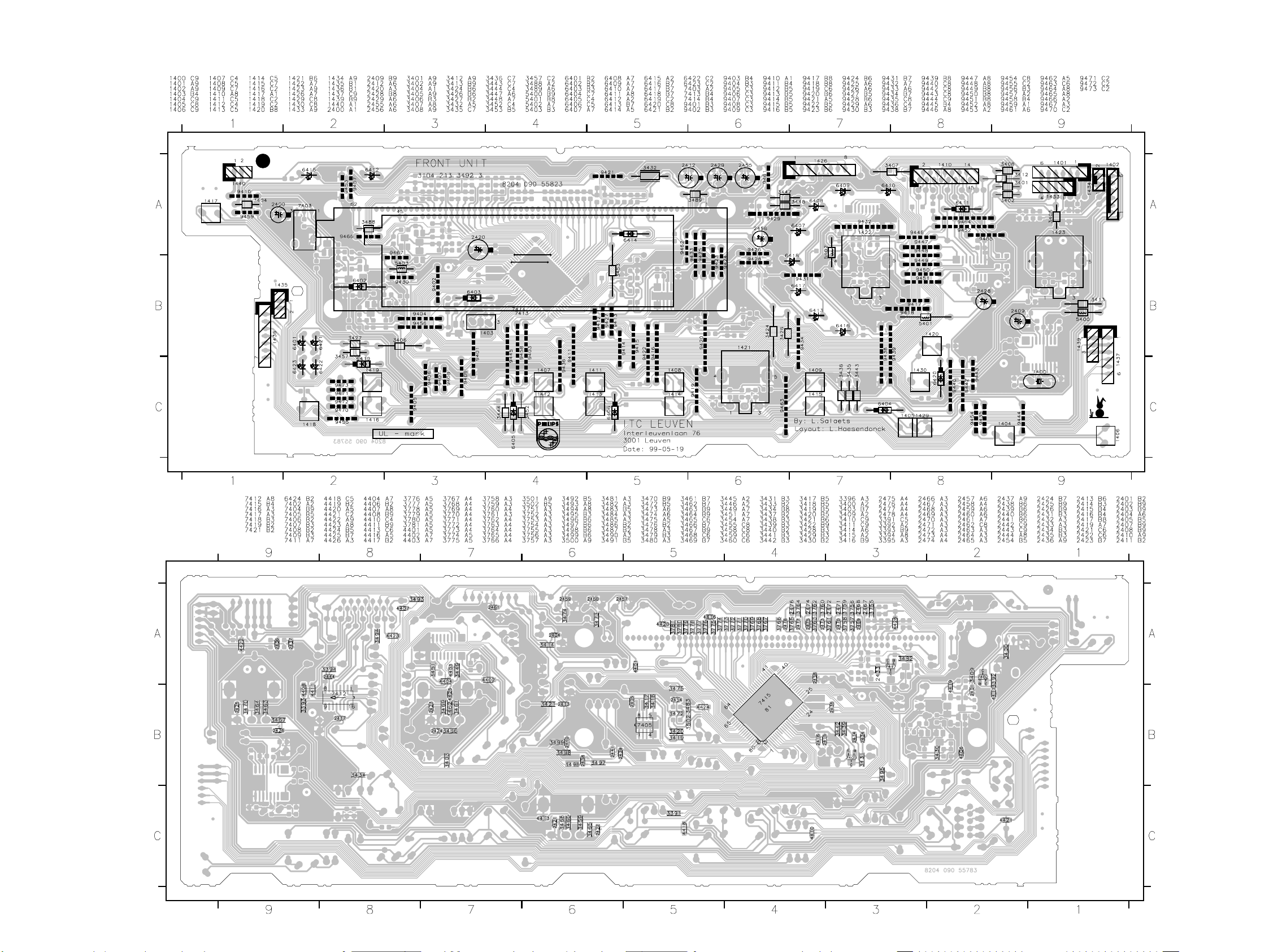
6-7 6-7
FRONT BOARD - COMPONENT & COPPER SIDE VIEW
This assembly drawing shows a summary of all possible versions. For components used in a specific version see schematic diagram respectively partslist.
This assembly drawing shows a summary of all possible versions. For components used in a specific version see schematic diagram respectively partslist.
Page 24
ELECTRICAL PARTSLIST - FRONT BOARD
6-8 6-8
POS.
NO
1400 N 4822 242 11033 CRYSTAL(4,332MH)
1403 4822 242 72066 CST8,00MT
1404 4822 276 13114 SWITCH, PUSH BUTTON
1406
4822 276 13114 SWITCH, PUSH BUTTON
1409
1410 4822 265 10981 15FE-BT-VK-N
1411
4822 276 13114 SWITCH, PUSH BUTTON
1416
1418 4822 276 13114 SWITCH, PUSH BUTTON
1419 4822 276 13114 SWITCH, PUSH BUTTON
1421 4822 273 10372 SWITCH, ROTARY
1422 4822 273 10372 SWITCH, ROTARY
1423 4822 273 10365 ROTARY ENCODER 24P
1424 4822 265 11584 1P YKB21-5209
1428 4822 265 11336 3P. FEM. CINCH
1429 4822 276 13114 SWITCH, PUSH BUTTON
1430 4822 276 13114 SWITCH, PUSH BUTTON
8002 4822 320 12706 FFC 15P - 220MM
2400 4822 124 41584 100UF 20% 10V
2402 N 5322 122 31647 1NF 10% X7R 63V
2403 3000 N 5322 116 80853 560PF 5% NP0 63V
2404 5322 122 31647 1NF 10% X7R 63V
2405 5322 122 32654 22NF 10% X7R 63V
2407 N 5322 122 34099 470PF 10% X7R 63V
2408 N 5322 122 32654 22NF 10% X7R 63V
2409 N 4822 124 22652 2,2UF 20% 50V
2410 N 5322 122 32654 22NF 10% X7R 63V
2412 4822 124 41751 47UF 20% 50V
2413 5322 122 32654 22NF 10% X7R 63V
2414 5322 122 32654 22NF 10% X7R 63V
2415 5322 122 32658 22PF 5% 50V
2416 5322 122 32658 22PF 5% 50V
2417 5322 122 32654 22NF 10% X7R 63V
2419 4000 5322 122 32654 22NF 10% X7R 63V
2420 4822 124 23432 100UF 20% 10V
2421 5322 122 32654 22NF 10% X7R 63V
2422 5322 122 32654 22NF 10% X7R 63V
2423
5322 122 32654 22NF 10% X7R 63V
2426
2427 5322 122 31647 1NF 10% X7R 63V
2428 4822 124 12032 4,7UF 20% 50V
2429 4822 124 41751 47UF 20% 50V
2430 4822 122 33575 220PF 5% NP0 63V CASE 0805
2431 4000 5322 122 32531 100PF 5% NP0 50V
2432 4000 5322 122 32531 100PF 5% NP0 50V
2433 5322 122 32531 100PF 5% NP0 50V
2434 4822 126 14076 220N 25V. P8020
2435
4822 122 33575 220PF 5% NP0 63V CASE 0805
2441
2442 N 4822 126 13692 47PF 1% NP0 63V
2443 N 4822 126 13692 47PF 1% NP0 63V
2444 5322 122 32654 22NF 10% X7R 63V
2445 5322 126 10223 4,7NF 10% X7R 63V
2447 5322 126 10223 4,7NF 10% X7R 63V
2448 5322 122 31647 1NF 10% X7R 63V
2449 5322 122 31647 1NF 10% X7R 63V
2454 5322 122 32654 22NF 10% X7R 63V
2455 4822 124 41751 47UF 20% 50V
2456 4822 124 40433 47UF 20% 25V
2457
5322 122 32654 22NF 10% X7R 63V
2461
2462 5322 122 31647 1NF 10% X7R 63V
2463
4000 5322 122 32531 100PF 5% NP0 50V
2466
MODEL
VERS.
COLOR
PART NO. DESCRIPTION
MISCELLANEOUS
CAPACITORS
POS.
NO
2467
2478
4000 N 5322 116 80853 560PF 5% NP0 63V
3391 4822 051 10102 1K00 2% 0,25W
3392
3394
3395 4000 4822 051 20008 0R00 JUMP. (0805)
3396 3000 4822 051 10102 1K00 2% 0,25W
3400 4822 051 20479 47R00 5% 0,1W
3401 4822 050 21003 10K00 1% 0,6W
3402 4822 050 21003 10K00 1% 0,6W
3403 4822 117 11507 6K8 1% 0,1W
3404 4822 116 52219 330E 5% 0,5W
3405 4822 116 52257 22K 5% 0,5W
3406
4822 050 21003 10K00 1% 0,6W
3408
3409 4822 051 10102 1K00 2% 0,25W
3410 N 4822 117 11449 2K2 1% 0,1W
3411 N 4822 117 13579 220K 1% 0.1W RC12H 0805
3412 3000 4822 050 21003 10K00 1% 0,6W
3413 N 4822 050 11002 1K00 1% 0,4W
3414 4822 051 10102 1K00 2% 0,25W
3416 N 4822 117 10833 10K 1% 0,1W
3417
4822 117 10833 10K 1% 0,1W
3421
3422 N 4822 117 10833 10K 1% 0,1W
3424 4822 050 11002 1K00 1% 0,4W
3426 4822 050 11002 1K00 1% 0,4W
3427 4822 116 83868 150R 5% 0,5W
3430 4822 051 20223 22K00 5% 0,1W
3431 4822 117 10833 10K 1% 0,1W
3432 4822 052 10478 4R70 5% 0,33W
3434 4822 051 20223 22K00 5% 0,1W
3435 4822 116 52257 22K 5% 0,5W
3436 4822 116 52257 22K 5% 0,5W
3439 4822 117 10833 10K 1% 0,1W
3442 4822 117 10837 100K 1% 0.1W
3443 4822 116 52219 330E 5% 0,5W
3444 4822 116 52219 330E 5% 0,5W
3445 4000 4822 117 13577 330R 1% RC12H 0805 1,25W
3446 4000 4822 117 13577 330R 1% RC12H 0805 1,25W
3447 4822 116 52219 330E 5% 0,5W
3448 4000 4822 116 52219 330E 5% 0,5W
3449 4822 117 10837 100K 1% 0.1W
3451 4822 117 10833 10K 1% 0,1W
3452 4822 116 52219 330E 5% 0,5W
3453 4822 116 52219 330E 5% 0,5W
3454 3000 4822 051 20008 0R00 JUMP. (0805)
3455 U, K 4822 051 20223 22K00 5% 0,1W
3457 4822 116 52219 330E 5% 0,5W
3458 4822 117 13577 330R 1% RC12H 0805 1,25W
3459
4822 117 10833 10K 1% 0,1W
3464
3465
4822 117 11503 220R 1% 0.1W
3470
3471 4822 051 10102 1K00 2% 0,25W
3472 4822 051 10102 1K00 2% 0,25W
3473 4822 051 20008 0R00 JUMP. (0805)
3474 4822 051 20008 0R00 JUMP. (0805)
3475 4822 117 10837 100K 1% 0.1W
3476 4822 117 10837 100K 1% 0.1W
3477 4822 117 12521 68R 1% 0,1W
3478 4000 4822 117 10837 100K 1% 0.1W
3479 4000 4822 051 10102 1K00 2% 0,25W
3480 4000 4822 117 10837 100K 1% 0.1W
3481 4000 4822 051 10102 1K00 2% 0,25W
MODEL
VERS.
COLOR
PART NO. DESCRIPTION
5322 122 32531 100PF 5% NP0 50V
RESISTORS
4822 051 20223 22K00 5% 0,1W
POS.
NO
3482 4822 117 10837 100K 1% 0.1W
3483 3000 4822 117 10837 100K 1% 0.1W
3484 4000 4822 051 10102 1K00 2% 0,25W
3485 4000 4822 051 20008 0R00 JUMP. (0805)
3486 4822 051 20472 4K70 5% 0,1W
3487 4822 117 10833 10K 1% 0,1W
3488 3000 4822 050 24708 4R70 1% 0,6W
3489 3000 4822 050 24708 4R70 1% 0,6W
3490 3000 4822 051 20008 0R00 JUMP. (0805)
3492 4822 117 10837 100K 1% 0.1W
3493
4822 051 20471 470R00 5% 0,1W
3501
3502 4000 4822 051 10102 1K00 2% 0,25W
3751 4000
4822 051 20333 33K00 5% 0,1W
3754 4000
3755
4822 051 20333 33K00 5% 0,1W
3781
4401
4822 051 20008 0R00 JUMP. (0805)
4404
4406
4822 051 20008 0R00 JUMP. (0805)
4408
4410 4822 051 20008 0R00 JUMP. (0805)
4411 4822 051 20008 0R00 JUMP. (0805)
4413 4822 051 20008 0R00 JUMP. (0805)
4416
4822 051 20008 0R00 JUMP. (0805)
4426
4450 4822 051 20008 0R00 JUMP. (0805)
5400 N 4822 157 11477 LAL02TB2R2J
5401 4822 157 11477 LAL02TB2R2J
5402 4000 4822 157 11477 LAL02TB2R2J
5403 4822 157 11477 LAL02TB2R2J
6400 9322 100 14682 LTL1214A
6403
4822 130 30621 1N4148
6406
6407
4000 4822 130 82978 LTL-16KPE-P
6409
6410 4822 130 82978 LTL-16KPE-P
6411 3000 4822 130 30621 1N4148
6412 4000 4822 130 82978 LTL-16KPE-P
6413 4000 4822 130 82978 LTL-16KPE-P
6414 4822 130 30621 1N4148
6415
4000 4822 130 82978 LTL-16KPE-P
6418
6419 4822 130 30621 1N4148
6420 4822 130 30621 1N4148
6422 4822 130 82978 LTL-16KPE-P
6423 4822 130 82978 LTL-16KPE-P
6424 4822 130 83757 BAS216
7402 4822 130 11607 PDTA144ET
7403 4822 130 10165 GP1U28XP
7404 N 4822 209 31981 SAA6579T
7405 4822 209 17445 M24C08-MN6
7409 4822 130 60511 BC847B
7411 4000 5322 209 11306 HEF4094BT
7412 5322 209 11306 HEF4094BT
7413 4000 2722 171 07179 16-BT-68GK
7414 3000 2722 171 07178 12-BT-113GK
7415 3000 4822 209 17446 TMP87CS71F/FR755.1
7415 4000 3103 308 83880 TMP87CS71F/SR4000
MODEL
VERS.
COLOR
PART NO. DESCRIPTION
FILTERS
DIODES
TRNSISTORS & ICs
POS.
NO
7416 4000 4822 130 60511 BC847B
7417 4822 130 60511 BC847B
7418 4000 4822 130 60511 BC847B
7419 9340 310 30215 PDTC144ET
7421 4822 130 11607 PDTA144ET
MODEL
VERS.
COLOR
PART NO. DESCRIPTION
Page 25

7B-1 7B-1
BLOCK DIAGRAM
TUNER BOARD
ECO 5
systems
A
AM-FRAME AERIAL
B
FM
1101
(1102)
V
Loop
V
Loop
1103
10,7 MHz
FM
Det.
AFC
AFC -
2
buffer ampl.
5
LF filter
1018 11
AFC +
20
RDS
(MPX)
VCO
Decoder
CONTROL
programmable
Reference
Oscillator
Stereo
output ports
right
left
stereo
clock
data
enable
P1
P0
75kHz
V
A V
Stab
FM-RF
V
Loop
3393733
43
FM
frontend
FM-Osc.
5
AM-Osc.
6
AM-RF
2
AM
Frontend
C
V
Loop
1
8
V
Loop
V
A
Stab
B
V
Stab
Charge
pump
38
34
723
Vdd Vcc1
10,7 MHz 10,7 MHz
FM
Mixer
FM
Osc.
AM
Osc.
AM
Mixer
22
Vcc2
V
IF1
Pre-
scaler
plexer
AM IF
4140 36 193244 25
AV
Stab
Stab
B
Stab
35 9
Discriminator
IF2
RADIO IC
TEA 5757T
Multi-
AM
Det.
AGC
450kHz450kHz450kHz
BV
Stab
B
Vcc1
Vdd
Vcc2
1124
Vcc
right
left
(MPX)
4
1
3
1126
1121
4 6
1
RDS
ECO5 sys., 240698
1
4
15
14
24
27
28
29
31
30
Version
MW/LW
AM-RF,
AM-Osc.
4
stereo
clock
data
enable
TUNER BOARD ECO5
TABLE OF CONTENTS
Blockdiagram ........................................................... 7B-1
Adjustment table ...................................................... 7B-2
Component layout .................................................... 7B-3
Circuit diagram ......................................................... 7B-4
Parts list ................................................................... 7B-5
Page 26

7B-2 7B-2
TUNER ADJUSTMENT TABLE
( ECO5 FM/MW- and FM/MW/LW - versions with AM-frame aerial )
Waverange Input frequency Input Tuned to Adjust Output Scope/Voltmeter
VARICAP ALIGNMENT
FM
87.5 - 108MHz
(65.81 - 74, 87.5 - 108MHz)
MW
FM/AM-version, 10kHz grid
530 - 1700kHz
FM/MW-version, 9kHz grid
531 - 1602kHz
LW
153 - 279kHz
MW
FM/MW/LW- version, 9kHz grid
531 - 1602kHz
FM IF
continuous wave
FM RF
FM
87.5 - 108MHz
(65.81 - 74, 87.5 - 108MHz)
VCO
FM
continuous wave
10.7MHz, 50mV
108MHz
87.5MHz
(65.81MHz)
98MHz, 1mV
A
mod=1kHz
∆f=±22.5kHz
A
108MHz
87.5MHz
(65.81MHz)
1700kHz
530kHz
1602kHz
531kHz
279kHz
153kHz
1602kHz
531kHz
IC 7101
shortcircuit
to block AFC
21
2141
108MHz 2155
87.5MHz
(65.81MHz)
98MHz
5130
check
5123
check
5123
check
5122
check
5123
check
5119FM
1
2F
4
8V ±0.2V
4.3V ±0.5V
(1.2V ±0.5V)
8V ±0.2V
1.1V ±0.4V
6.9V ±0.2V
1.1V ±0.4V
8V ±0.2V
1.1V ±0.4V
8V ±0.2V
1.1V ±0.4V
0 ± 3 mV DC
MAX
5131
3142 152kHz ±1kHz
3
TUNER ADJUSTMENT TABLE
( ECO5 FM/MW- stereo versions with AM-frame aerial )
Waverange Input frequency Input Tuned to Adjust Output Scope/Voltmeter
VARICAP ALIGNMENT
FM
87.5 - 108MHz
FM Japan
76 - 90MHz plus
Ch1 95.75MHz, Ch2 101,75MHz,
Ch3 107.75MHz
MW
FM/AM-version, 10kHz grid
530 - 1700kHz
MW
FM/MW-version, 9kHz grid
531 - 1602kHz
108MHz
87.5MHz
107,75MHz
76MHz
1700kHz
530kHz
1602kHz
531kHz
5130
check
5130
check
1
5123
check
5123
check
FM IF
IC 7101
10.7MHz, 50mV
continuous wave
shortcircuit
to block AFC
21
2141
5119FM
2F
FM RF
FM
87.5 - 108MHz
FM Japan
76 - 90MHz plus
Ch1 95.75MHz, Ch2 101,75MHz,
Ch3 107.75MHz
108MHz
87.5MHz
107.75MHz
76MHz
A
mod=1kHz
∆f=±22.5kHz
108MHz
87.5MHz
107.75MHz
76MHz
2155
5131
5
2155
5131
VCO
98MHz, 1mV
1)
FM
(83MHz for Japan)
continuous wave
A
98MHz
(83MHz for Japan)
3142 152kHz ±1kHz
3
8V ±0.2V
4.3V ±0.5V
8V ±0.2V
2.4V ±0.5V
8V ±0.2V
1.1V ±0.4V
6.9V ±0.2V
1.1V ±0.4V
0 ± 3 mV DC
MAX
1)
AM IF
IC 7101
36
MW
AM AFC
MW
450kHz
connect pin 6 of
IC 7101 (AM Osc.)
with short wire to
ground (pin 4)
C
∆f=±15kHz
= 3mV
V
RF
C
continuous wave
IC 7101
see
remark
100nF
220R
40
100nF
220R
2)
5111
5112
5114
4
2
0 ± 2 mV DC
VRF = 10mV
3)
AM RF
4)
MW
FM/MW/LW- and FM/MW-version
( 9kHz grid)
531 - 1602kHz
LW
MW
FM/AM-version, 10kHz grid
530 - 1700kHz
Use service test program. By selecting the TUNER TEST test frequencies will be stored as preset frequencies automatically.
1)
If sensitivity of frequency counter is too low adjust to max. channel separation
(input signal: stereo left 90% + 9%, adjust output on right channel to minimum)
3)
For AM RF adjustments the original frame antenna has to be used !
Repeat
1494kHz
558kHz
B
1494kHz
558kHz
198kHz
1500kHz
560kHz 5102
∆f = ±30kHz
V
as low as
RF
possible
1500kHz
560kHz
2)
RC network serves for damping the IF-filter while adjusting the other one.
4)
MW has to be aligned before LW.
2106
5102
5103198kHz
2106
4
f
o
symmetric
f
o
symmetric
ECO5, discr. coil, 090797
max.
max.
AM IF
IC 7101
36
C
MW
450kHz
AM AFC
MW
connect pin 6 of
IC 7101 (AM Osc.)
with short wire to
ground (pin 4)
IF stereo module
MW
3)
AM RF
MW
FM/MW-version, 9kHz grid
531 - 1602kHz
MW
FM/AM-version, 10kHz grid
530 - 1700kHz
Use service test program. By selecting the TUNER TEST test frequencies will be stored as preset frequencies automatically.
1)
If sensitivity of frequency counter is too low adjust to max. channel separation
(input signal: stereo left 90% + 9%, adjust output on right channel to minimum)
3)
For AM RF adjustments the original frame antenna has to be used !
1494kHz
558kHz
1500kHz
560kHz 5102
∆f=±15kHz
= 3mV
V
RF
C
continuous wave
VRF = 10mV
100nF
E
50R
∆f=±15kHz
V
= 1mV
RF
B
∆f = ±30kHz
V
as low as
RF
possible
see
remark
100nF
220R
IC 7101
40
100nF
220R
2)
1494kHz
558kHz
1500kHz
560kHz
2)
RC network serves for damping the IF-filter while adjusting the other one.
Repeat
5111
5112
5114
5240
2106
5102
2106
5
2
4
4
f
o
symmetric
0 ± 2 mV DC
f
o
symmetric
ECO5 AM stereo, discr.coil 090797
max.
max.
max.
Page 27

7B-3 7B-3
1101 A 1
1102 A 1
1103 C1
1104 B 1
1105 A 1
1119 C5
1120 A 5
1130 B 5
1131 B 5
2104 A 2
2105 A 1
2106 C2
2107 C2
2110 C2
2115 C1
2123 A 2
2125 A 2
2128 C3
2129 C4
2130 A 4
2133 A 4
2135 B 5
12345
ECO 5 TUNER BOARD /
A
A
FM 75 OHM
SW
1102
1101
1104
SW
FM 300 OHM
B
D
B
FRAME
C
AM FRAME AERIAL
AM
1
2115
SW-RF
1
1103
1105
FM
4
1
2137 C5
2138 A 5
2144 B 5
2148 B 4
2155 A 3
2162 A 2
3105 B 3
3110 A 2
3132 B 3
3142 A 4
3147 B 5
6103
6104
9100
6102
2105
C
A
9123
5106
2107
5102
MW-RF
9111
3149 C5
3152 A 5
3154 C5
3157 B 5
3158 A 5
3159 A 5
3160 A 5
3161 A 5
3170 C5
3171 C5
3172 C5
component side view
3110
9128
9113
2162
6101
9105
5
E
MW-OSC
9114
7104
5103
LW-RF
5123
5124
SW-OSC
5104
SW-ANT
6109
9121
2104
2123
2125
C
9117
SW-RF
2106
MW-RF
2110
LW-RF
98-05-14B339623033103
1 CF
5122
LW-OSC
B
C
5105
9130
7105
3173 A 5
5102 C2
5103 C2
5104 C2
5105 B 2
5106 B 2
5109 B 4
5110 B 4
5111 C3
5112 C4
5113 B 3
5131
FM-RF
9134
3132
6106
7107
B
7102
A
2155
C
FM-RF
5126
9101
9122
9133
5114 C4
5115 A 4
5116 A 4
5119 B 5
5120 B 4
5121 B 4
5122 B 3
5123 B 2
5124 B 2
5126 B 3
5127 B4
A
9125
9129
3105
AM-IF1
2128
5130
FM-OSC
9115
5113
5111
C
2129
5130 A 3
5131 A 3
6101 A 2
6102 A 1
6103 A 1
6104 A 2
6106 B 3
6107 C5
6109 C2
6120 C4
7102 A 3
4
5115
5116
2130
4
3
5109
5114
AM-AFC
7119
5112
AM-IF2
1122
5110
7104 C2
7105 C3
7107 B 3
7119 C4
9100 A 2
9101 B 3
9105 B 2
9111 C2
9113 B 2
9114 B 2
9115 B 3
VCC
VCC2
1124
E
2133
2148
5
9119
9124
GND
RIGHT
3142
VCO
5120
21
1
5127
6120
9120
1119
VCC2
GND
VCC
LEFT
2144
1
9117 B 2
9118 B 4
9119 C4
9120 B 4
9121 A 2
9122 C3
9123 B 1
9124 C4
9125 A 3
9126 B 5
9128 A 2
CLOCK
STEREO
DATA
ENABLE
9136
1
3158
3159
9131
2138
5119
DISCRIMI-
NATOR
3147
31713172
3170
9118
3149
SEARCH
SENS.
Voltage multiplier board
6107
DATA
1127
9137
2135
2137
9129 B 3
9130 C3
9131 A 5
9133 C3
9134 B 3
9136 A 5
9137 A 5
GND
MPX
ENABLE
1123
1126
11
3161
3160
9126
11
1
1
3154
1120
1125
3173
3157
AM-IF
GND
+FM
R-FM
L-FM
L out
R out
VCOkill
STSIG
STEREO
V+
11301131
1121
3152
2101 C4
2102 C4
2103 C3
2108 A 4
2109 A 4
2111 A 2
2112 B 5
2113 A 4
2114 A 4
2116 B 3
2117 A 3
3
A
B
Connector for
AM - stereo Module
C
2118 B 4
2119 B 4
2120 B 4
2122 B 3
2124 A 5
2126 C2
2127 C2
2131 C2
2132 C1
2134 C1
2136 B 1
2139 B 2
2141 B 1
2142 B 1
2143 A 1
2145 C1
2146 C1
2147 C1
2149 B 2
2150 B 2
2151 C2
2152 C3
54321
ECO 5 TUNER BOARD /
A
AM
FRAME
D
SW
B
A
C
2153 C3
2154 C3
2156 C4
2157 B 4
2158 B 4
2159 C2
2160 C4
2161 A 3
2163 A 2
2164 B 1
2165 B 3
2124
1
4
2112
FM
A
2105
6111
2166 B 2
2167 B 2
2168 B 1
3101 C3
3102 C3
3103 C3
3104 B 3
3106 C4
3108 A 4
3109 A 4
3111 A 3
copper side view
4101
54
3133
3137
3106
6110
5
4106
4153
3136
7124
E
4155
2157
2118
9114
6101
18
6105
2119
C
3112 A 3
3113 A 2
3114 A 3
3115 A 3
3116 A 3
3117 B 4
3118 B 3
3119 A 3
3120 B 4
3121 A 3
3122 B 3
98-05-14B339623033103
4102
2108
3109
2109
3180
3108
2114
2113
3120
7120
4108
7122
B
C
3134
2120
7123
2158
2156
4107
2101
2102
7106
3117
C
2160
2116
3118
2122
3115
3121
3168
3125
B
7109
3123
4151
7121
3127
3102
3123 A 3
3125 A 3
3126 B 3
3127 B 3
3128 B 3
3133 B 4
3134 B 4
3136 B 4
3137 B 4
3140 B 2
3141 C2
4110
3116
3111
7108
2117
3122
3126
3128
2154
C
A
6131
2103
3112
A
4109
3103
4154
3143 C2
3144 C2
3145 C2
3146 A 1
3148 A 1
3153 C2
3155 A 2
3156 A 1
3167 C2
3168 B 3
3169 B 2
3114
4105
4152
2165
4157
3181
2153
2152
2161
3101
4104
3119
4150
6130
C
2111
2150
3104
4156
1
4120
3143
3167
3113
2149
4103
2151
3175 A 2
3176 C2
3177 A 1
3178 A 1
3179 A 1
3180 A 4
3181 C3
4101 A 4
4102 A 4
4103 C2
4104 A 2
E
3175
4159
3
4
3
4
7101
1
2
2159
2127
2126
3176
7103
3144
2163
3141
E
4162
9119
2167
3
2
3145
2139
3153
4105 B 3
4106 B 4
4107 C4
4108 B 4
4109 A 3
4110 A 3
4111 C1
4120 C2
4150 B 2
4151 B 3
4152 B 3
3155
3169
2166
3140
2168
2131
2132
4158
2143
3177
2141
2164
2142
4153 B 4
4154 C3
4155 A 4
4156 A 2
4157 B 3
4158 C2
4159 A 2
4160 A 1
4161 A1
4162 C1
4163 C1
3146
3148
7125
3178
3156
2145
3179
2146
4161
11
1
2136
2147
6105 A 4
6110 A 4
6111 B 4
6130 C2
6131 C3
7101 B 2
7103 C2
7106 A 3
7108 A 3
7109 A 3
7111 A 1
4160
7111
4111
2134
4163
7120 B 4
7121 B 3
7122 B 4
7123 B 4
7124 C4
7125 A 1
2
3
A
B
C
This assembly drawing shows a summary
of all possible versions.
For components used in a specific version
see schematic diagram respectively partslist.
marked components to be assembled
Local/DX
as service solution for
- switching
2SA...
B
C
E
ECO5 3396 stage .2, 250698
BC...
E
B
C
12345
C
A
C
41..
Chip jumper
(not all items shown
EB
in schematic diagram)
marked components to be assembled
as service solution for
51 CF 4
Local/DX
- switching
This assembly drawing shows a summary
of all possible versions.
For components used in a specific version
see schematic diagram respectively partslist.
ECO5 3396 stage .2, 250698
54321
Page 28

7B-4 7B-4
TUNER BOARD ECO5
y
FM
FM 50 OHM
B
1101
2
1
x
1102
1
2
T003
1103
2
1
T001
T002
6103
MW/LW-RF
T005
T006
w
3108
LW=high
2k2
LW
P0
7105
4k7w3109
BC338-40
MW=high
1N4148
w
6104
w
2108
A
A
B
C
D
E
F
G
H
I
J
K
L
M
N
300 OHM
AM FRAME AERIAL
1N4148
7104
BC338-40
100p
w
2109
451 6 7 8 9 10 11 12 13 14 152 16 17 18 19 20 213
Service Solution for
Local/DX - switching
remove
2105
100p
w
10p
451 6 7 8 9 10 11 12 13 14 152 16 17 18 19 20 213
9100
41554156
9128
3106
9114
9119
P0
6
6101
BA484
10k
5102
2
1
5103
/
y
w
Systems
printed
MW
6
5
3
u
4
4102
34
2
u
1
4101
MW
2106
2104
100p
1
2101
HN1V02H
3-11p
w_4-20p
P0
100p
47p
9101
2107
(if 1102 is used)
(if 1101 is used)
26105
7
3110
47R
1u
3125
10k
6106
3120
1101 A 1
1102 B 2
1103 D 2
A
B
C
D
pp
E
to/from
CONTROL BOARD
F
G
Source Selector part
to/from
COMBI BOARD /
H
I
J
K
L
M
N
1121 E20
1124 G20
1126 E20
1130 I20
1131 I20
2101 C 6
2102 G 7
2103 D 9
2104 B 6
2106 F 5
2107 G 6
2108 G 3
2109 G 3
2111 C13
2120 L11
2122 N11
2123 M11
2125 M11
2126 G 9
2127 G10
2128 C11
2129 C 9
2130 H17
2131 I10
2132 I10
2133 H11
2134 J17
2135 J18
2136 J17
2137 J18
2138 H12
2139 H13
2140 H14
2141 H14
2142 H14
2143 I17
2144 H17
2145 G16
2146 F15
2147 F16
2148 F16
2149 C15
2150 B13
2152 F 7
2153 E 8
2154 E 7
2155 D 8
2158 M11
2159 F 9
2160 M12
2161 D16
2163 E16
2164 H14
2165 C 9
2166 G16
2167 F16
2168 I 13
3101 E 7
3102 E 7
3103 C 8
3104 B11
3105 C 7
3108 E 3
3109 F 2
3110 F 6
3113 C13
3119 B13
3120 C 6
3123 M 7
3125 M 6
3128 M 8
3132 L 9
3134 M12
3137 M13
3140 I13
3141 G10
3142 G 9
3143 I10
3144 I10
3145 H10
3146 I17
3147 I15
3152 H18
3153 H19
3154 H18
3155 H17
3156 G17
3157 F17
3158 F18
3159 F18
3160 E18
3161 E18
3167 G18
3169 G15
3170 F17
3171 H15
3175 B16
3176 J 9
3177 I18
3178 I15
3179 I16
3180 M7
4101 G 5
4102 F 5
4103 G 9
4104 B13
4105 B11
4106 K12
4108 L 9
5102 E 4
5103 F 4
5109 B13
5110 B14
5111 A13
5112 A15
5113 B12
5114 C16
5119 I 12
5120 H13
5121 F15
5122 M11
5123 L11
5130 E 8
5131 D 8
6103 C 2
6104 C 3
6105 K12
6105 E 6
6106 C 6
6107 H17
6120 G16
6130 E 7
6131 D 7
7101 G11
7102 D 8
7103 I 9
7104 E 3
7105 F 2
7109 M 7
7111 F18
7119 B13
7122 M 9
7124 M13
7125 I16
9100 B 4
9101 C 6
9117 L10
9128 A 4
AM-IF2AM-IF1
5111
T046
6
z
5113
x
4105
3104
C
3105
220R
FM-RF
1N4148
0R
6131
3102
100k
3101
33k
s_5k6
10n
2102
Vdd
w
w
7109
w
4k7
3123
BC858B
w
3180
T009
Q-MULTIPLIER
2SA838B
x
4p7
2154
2155
1SV228
6130
s_560p
2152
33n
FM-OSCILLATOR
1
Vdd
LW=high
22k
7102
5131
3-11p
printed
15p s_12pt_2p2
3128
2k2
REF
3103
5130
5
to 3103
REF
2129
100u
18k
t_18k
2103
2165
100n
1n
F
33p
2159
Vcc1
VCO
3141
3142
100k
56k
2126
330p
4103
2127
220n
r
r
7103
BC858C
r
3176
1k
AM-OSCILLATOR
T011
3132
4108
47R
w
7122
BC848C
w
0.7V
Ripple
T043
2.1V
2
0V
AM-RF
3
0V
FM-RF
4
RF-GND
5
0V
FM-OSC.
6
0V
AM-OSC.
T040
7
8V
Vcc1
8
I-TUNE
1.3V
9
VCO
1V
T012
10
0.7V
AF-Out
11
1.2V
MPX-IN
2131
Vcc1
3143
470n
22k
r
3144
1k
buffer amplifier
5123
u
6
9117
5122
6
CONTROL
180R
T044
10u
2128
0.15V 0.7V 1V 0.7V 0.7V1.4V 1.4V 1.4V 1.4V 1.4V
AM Det.
RF-GND
AGC
FM-In
AM IF
AGC
LPF
12 13 14 15 16 17 18 19120 21 22
0.1V
2k2
3145
2132
MPX
to 1121
w
Charge
Pump
470n
FM
Frontend
FM
OSC
Vcc2
2133
MW
LW
Ripple
MUTE
34
2
1
34
2
1
1u
2158
AM
Frontend
STAB
DECODER
left
10p_w
scaler
STEREO
w
w
SFU450B
AM-IF1-in
AM
OSC
Pre-
Multi-
plexer
V
A
STAB
STABILIZER
TEA5757
7101
z_TEA5759
right
6
DISCRIMINATOR
6
6105
5
4106
22p
2120
w_27p
22k
3134
2125
560p
390p
2123
3n3
2122
T013
AM
MIXER
BV
2138
u
AM
PILOT
3
2160
4041424344
Mixout
AGC
AGC
V
dd
FILTER
2u2
5119
HN1V02H
22n
34
450 kHz 450 kHz
1
2150
t
2
3119
330R
FM-IF1
x
5109
4104
t
7119
2SC1047
t
t
1k
2111
100p
3113
FM
A
STAB
Mixout
AM
IF
FM
MIXER
AM
DET
FM
DET
Mono/
Stereo
IF GND
FM-Demod.
15p
2139
5120
34
2
82p
2168
1
3140
150R
3140 and 5120
provisional as
alternative
w
7124
BC848C
E
100n
T014
FM-IF1 in
AM-IF2
FM
IF1
AGC
FM
IF2
AFC
AFC+
AFC-
1.2V 2V
1.2V1V1V0.7V0.7V0.7V0.8V
T016
T041
T042
(2140)
2164
470n
CDA10.7MG61KA
2
2140 exchanged by 2164
(SMD type 0805)
from layout stage 3317.9 onwards
respectively 3103 303 3380.1
and 3103 308 3396.1
w
3137
P0
22k
MW=high
FM-IF2
FM-IF2
CONTROL
XTAL
OSC.
Fieldstrength Indic.
2141
100n
5112
34
V
5110
STAB
Vcc2
2142
343536373839
Dig.GND
Mono/
Stereo
Vdd
11V
T017
BV
FM-IF2
AM-AFC
P1
P0
Write
Enable
DATA
CLOCK
100n
1
3171
330R
3147
3M3
33
32
31
30
29
28
27
26
25
1.3V
24
23
0.7V
1.4V
stereo 0.3V
mono 4.9V
8V
z
z
3178
1
2
3
2
T047
2149
T015
T037
T032
2146
5121
75KHz
3169
150k
Vdd
7125
BC848C
3M3
6105
HN1V02H
z
22n
220p
6
5114
3
1
2161
100n
2163
2147
2167
12p
2166
1n
8
7
6
54
z
3175
2k7
x
x
100n
220p
2148
2145
z
1M
3179
Chip jumper
AM-IF
to 1130,1131
AM Stereo module
AM-AFC
450 kHz
P1
Programmable
Output Ports
P0
220p
22n
P1
6120
Vcc1
8V
Vdd
8V
3157
100k
3170
100k
3156
100k
version detection
1N4148
2130
3155
T018
470R
z_100R
1u
2144
T045
6107
2143
220n
22R
3146
2136
2134
15n_y22n
15n_y22n
r....for RDS version only
s...for East European version (/14/34) only
t....for Japanese version (/06/26) only
u...for 2-band (FM/AM) version only
v...for SW-version 3.9-12.1MHz only
w...for LW only
41..
x....not for all versions
y....for USA version (/17/37) only
z....for AM-STEREO (/06/13/26/33) versions only
VERSION PROGRAMMING COMPONENTS
/00 FM/MW/LW
/00 FM/MW/LW/SW-Eu
/01 FM/MW-Stereo
/01 FM/MW
/01 FM/MW/SW-Ov
/06 FM-Japan/MW-stereo
/13 FM/MW-Stereo
/14 FM-OIRT/MW/LW
/17 FM/AM
/.. FM/MW/2xSW
/15 FM/MW/SW-Eu
3161
470R
3160
470R
3159
470R
3158
7111
BC848C
3167
220R
22n
3154
150R
z
10k
BZX79-C11
3177
x
2137
220n
2135
220n
470R
T020
T021
T022
T023
3152
470R
x
x
-
-
-
-
-
x
x
-
-
x = component mounted
SW = Software initialisation
MPX
from 3144
0.3V
0.2V
stereo 0.5V
mono 4.9V
T024
T025
T026
T027
3153
470R
T030
T031
Low=AM mono
P0
T033
T034
T035
T036
P1
T038
T039
AM-IF
Voltages measured while set is tuned to a strong transmitter
(11 - 14V)
V
typ. 12V
315731566120
-
-
-
x
-
x
-
x
-
-
x
x
-
--xx/14 FM-OIRT/MW
-
x
-
x
r
1121
1
GND
2
MPX
1126
1
3
2
4
3
5
4
6
1124
1
2
3
4
z
1130
z
1131
1
V+
2
stereo
3
STSIG
4
VCO-kill
5
R-out
6
L-out
7
L-FM
8
R-FM
9
+FM
10
GND
11
AM-IF
............. Vdc FM mode stereo
V
EVM
V
3170 remark
-
7111
not mounted
-
-
SW
x
x
-
SW
x
SW
---x/17 FM/AM-Stereo
x
x
xx
150kHz, 50mV
5V
0V
stereo stereomono
enable
data
3
clock
stereo
left
GND
4
right
Vcc
to/from
AM-stereo module
Signal path
FM
AM
MPX (Audio Frequency)
AF - left/right
Vdc MW mode
Vdc LW mode
ECO5 systems, discr.coil, 030998
Page 29

7B-5
ELECTRICAL PARTSLIST
TUNER ECO5
MISCELLANEOUS
1101 4822 267 31505
1102 4822 267 10283
SOCKET 2-POLE CLICKFIT, 300Ω
SOCKET COAX, IEC 75Ω
only for /17
not for /17
CAPACITORS
2101© 5322 122 32531 100pF 5% 50V
not for /17
2101 © 5322 122 32452 47pF 5% 63V only for /17
2102© 4822 122 33177 10nF 20% 50V
2103© 5322 122 34123 1nF 10% 50V
2104 4822 122 33195 100pF 10% 50V
2106 4822 125 60101 3-11pF TRIMCAP.
2107 4822 121 51319 1µF 20% 50V
2120© 5322 122 32658 22pF 5% 50V
2125 4822 121 51381 560pF 1% 400V
2126© 5322 122 31863 330pF 5% 50V
2127© 4822 126 13473 220nF 20% 50V
2128 4822 124 41579 10µF 20% 50V
2129 4822 124 41584 100µF 20% 10V
2130 4822 126 11585 22nF 20% 50V
2131© 4822 126 13482 470nF 20% 16V
2132© 4822 126 13482 470nF 20% 16V
2133 4822 124 40242 1µF 20% 63V
2134© 4822 126 13188 15nF 5% 63V
not for /17
2134 © 5322 122 32654 22nF 10% 63V only for /17
2135 4822 124 40746 0,22µF 20% 63V
2136© 4822 126 13188 15nF 5% 63V
not for /17
2136© 5322 122 32654 22nF 10% 63V only for /17
2137 4822 124 40746 0,22µF 20% 63V
2138 4822 124 41576 2,2µF 20% 50V
2139© 4822 126 14236 15pF 5% 50V
2141© 4822 126 10002 100nF 20% 50V
2142© 4822 126 10002 100nF 20% 50V
2143© 4822 126 13473 220nF 20% 50V
2144 4822 124 40242 1µF 20% 63V
2145© 4822 122 33575 220pF 5% 50V
2146© 4822 122 33575 220pF 5% 50V
2147© 4822 122 33575 220pF 5% 50V
2148 4822 126 11585 22nF 20% 50V
2149© 5322 122 32654 22nF 10% 63V
2150© 4822 122 31947 100nF 20% 50V
2152© 4822 126 12105 33nF 5% 63V
not for /14
2152© 5322 116 80853 560pF 5% 63V only for /14
2153© 4822 122 32139 12pF 5% 63V only for /14
2153© 4822 122 32504 15pF 5% 50V not for /14
2155 4822 125 60101 3-11pF TRIMCAP.
2159© 5322 122 32659 33pF 5% 50V
2160© 5322 122 32654 22nF 10% 63V
2164© 4822 126 13482 470nF 20% 16V
2165© 4822 126 10002 100nF 20% 50V
2166© 5322 122 34123 1nF 10% 50V
2167© 4822 122 32139 12pF 5% 63V
2168© 4822 126 13695 82pF 1% 63V
RESISTORS
RESISTORS
3142 4822 100 11163 100kΩ TRIMPOT LIN.
3145© 4822 117 11449 2,2kΩ 1% 0,1W
3146© 4822 051 20229 22Ω 5% 0,1W
3152 4822 116 83883 470Ω 5% 0,16W
3153© 4822 051 20471 470Ω 5% 0,1W
3154 4822 116 83868 150Ω 5% 0,5W
3155© 4822 051 20471 470Ω 5% 0,1W
3156© 4822 051 20104 100kΩ 5% 0,1W
not for /14/17
3157 4822 116 52234 100kΩ 5% 0,5W only for /14
3158 4822 116 83883 470Ω 5% 0,16W
3159 4822 116 83883 470Ω 5% 0,16W
3160 4822 116 83883 470Ω 5% 0,16W
3161 4822 116 83883 470Ω 5% 0,16W
3167© 4822 117 11503 220Ω 5% 0,1W
3169© 4822 051 20154 150kΩ 5% 0,1W
3170 4822 116 52234 100kΩ 5% 0,5W
not for /14
3171 4822 116 52219 330Ω 5% 0,5W
4101© 4822 051 20008 CHIP JUMPER 0805
4102© 4822 051 20008 CHIP JUMPER 0805
4103© 4822 051 20008 CHIP JUMPER 0805
4104© 4822 051 20008 CHIP JUMPER 0805
4105© 4822 051 20008 CHIP JUMPER 0805
4106© 4822 051 20008 CHIP JUMPER 0805
4108© 4822 051 20008 CHIP JUMPER 0805
4111© 4822 051 20008 CHIP JUMPER 0805
4120© 4822 051 20008 CHIP JUMPER 0805
4150© 4822 051 10008 CHIP JUMPER 1206
4152© 4822 051 10008 CHIP JUMPER 1206
4153© 4822 051 10008 CHIP JUMPER 1206
4154© 4822 051 10008 CHIP JUMPER 1206
4157© 4822 051 10008 CHIP JUMPER 1206
4158© 4822 051 10008 CHIP JUMPER 1206
4159© 4822 051 10008 CHIP JUMPER 1206
COILS
5102 4822 157 71634 RF-COIL MW
5109 4822 242 70665 FM-IF FILTER 10,7MHZ
5110 4822 242 70665 FM-IF FILTER 10,7MHZ
5111 4822 158 60511 AM-IF FILTER 450kHz
5112 4822 157 70302 AM-IF FILTER 450kHz
5114 4822 157 70302 AM-IF FILTER 450kHz
5119 4822 157 11443 DISCRIMINATOR COIL
5121 4822 242 10261 QUARTZ 75kHz
5123 4822 157 60517 RF-COIL AM
5130 4822 156 30947 RF COIL 1,5 TURNS
5131 4822 156 30947 RF COIL 1,5 TURNS
DIODES
6103 4822 130 30621 1N4148
6104 4822 130 30621 1N4148
6105© 4822 130 83075 HN1V02H
6106 4822 130 30621 1N4148
6107 4822 130 34488 BZX79-C11
3101© 4822 051 20333 33kΩ 5% 0,1W
not for /14
3101© 4822 051 20562 5,6kΩ 5% 0,1W only for /14
3102© 4822 051 20104 100kΩ 5% 0,1W
3103© 4822 117 10965 18kΩ 2% 0,1W
3104© 4822 117 11448 180Ω 10% 0,1W
3105 4822 116 83872 220Ω 5% 0,5W
3110 4822 116 52195 47Ω 5% 0,5W
3120© 4822 051 20008 CHIP JUMPER 0805
3132 4822 116 52195 47Ω 5% 0,5W
3134© 4822 051 20224 220kΩ 5% 0,1W
3141© 4822 117 11148 56kΩ 1% 0,1W
6120 4822 130 30621 1N4148
6130© 4822 130 82833 1SV228
6131© 4822 130 82833 1SV228
TRANSISTORS
7102 4822 130 60093 2SA838B
7111© 5322 130 42136 BC848C
INTEGRATED CIRCUITS
7101© 4822 209 90924 TEA5757H/V1, RADIO IC
only for /14/17
Page 30

ELECTRICAL PARTS LIST
7B-6
TUNER ECO5 for 06 ( Japanese version)
1102 4822 265 20598
1130 4822 267 10749 CONNECTOR S11B-XH-A (11P)
2111 5322 122 32531 100pF 5%NP0 50V
2153 5322 122 33063 2.2pF 5% NP0 50V
3113 4822 051 10102 1k
3119 4822 051 20331 330
3134 4822 051 20223 22k
3147 4822 111 50499 3.3M
3155 4822 051 20101 100
3175 4822 117 12955 2.7k
3177 4822 117 10833 10k
3178 4822 051 20335 3.3M
3179 4822 051 20105 1M
4161 4822 051 20008 CHIP JUMPER. 0805
5113 4822 242 80989 FILTER SER. SFU450B 457kHz
5130 4822 157 70033 COIL-FM OSC
7101 TEA5759H/V1 RADIO IC
7119 4822 130 60163 2SC1047C
7125 5322 130 42755 BC847C BC848C
SOCKET COAX
Ω
Ω
Ω
Ω
Ω
Ω
Ω
Ω
Ω
YKD31-0468 75
2% 0,25W
5% 0,1W
5% 0,1W
5% 0,2W
5% 0,1W
1% 0,1W 0805
1% 0,1W
5% 0,1W
5% 0,1W
Ω
Page 31

7D-1
TUNER 95 BOARD
TABLE OF CONTENTS
Adjustment table ...................................................... 7D-2
Blockdiagram ........................................................... 7D-3
Component layout .................................................... 7D-4
Circuit diagram ......................................................... 7D-5
Parts list ................................................................... 7D-6
Page 32

7D-2
TUNER 95 bis Adjustment Table ( FM, MW, LW with Frame antenna)
Waverange Input frequency Input Set t uned to Adjust Output Scope / Voltmeter
VARICAP ALIGNMENT
FM (50)
87.5 - 108 MHz 87.5 MHz check 1.3 ... 2V
MW (9)
531 - 1602 kHz 531 kHz check
LW (3)
153 - 279 kHz 153 kHz check
FM – DETECTION
98 MHz 1mV
FM
continuous wave
short pin 21 (IC7101)
to ground
A
FM – VCO
98 MHz 1 mV
FM
A
continuous wave
DISTORTION
98 MHz 1 mV mixcoil
FM
90 % L + 98MHz inside Distortion
A
9 % pilot Tuner minimum
mod = 1kHz 1110
108 MHz check 7 ... 9V
1602 kHz 5123
6
279 kHz 5122
8.3V± 0.2V
1V± 0.4V
8.3V± 0.2V
1V± 0.4V
1
98 MHz 5107
98 MHz 3142
2
3
4
0mV± 3mV
152kHz± 1 kHz
AM – IF
450kHz 5111
∆
MW
f = 10kHz
Low as possible max. height
Swept signal MW 5112
100nF
50E
C
450kHz 5114
continuous wave
AM - RF
558kHz 558kHz 5102
MW
Mod = 1kHz MAX
30 % AM
1494 kHz 1494kHz 2106
B7
198kHz *
LW
mod = 1kHz 198kHz 5103 MAX
30 % AM
* Signal send via a frame antenna
(..) = tuning grid in kHz repeat
7
1
2
adjtable for 3104 217 04121/04341
symmetrical and
0mV± 2mV
Page 33

BLOCKDIAGRAM
7D-3 7D-3
+FM
10,7MHz
VCC1 VDD VCC2
7
63
+B AGC
FM FRONTEND
A
VCC1
STABILIZER
23
VDD
34 33
FM-IF235V Stab B
FM-IF2I V Stab A38AM-MIX Out40AM-IF1 In
1102
F 10,7 MHz
if
IF OutAnt1 71
Osc Out
F
a
F
o
GND4 8
f0 = fin + f
if
MT
MT 5
VT
AM-RF AM-OSC
10,7MHz
6
C
FM-IF1I In37
5 FM Osc.
8 I-Tune
2 AM-RF
FM
IF1
CHARGE
PUMP
AM
OSC.
Ripple AM-Osc.
1
6
AM
FRONTEND
FM GND
FM
IF2
AM
MIXER
RF GND17IF GND26Dig. GND42RF GND
34
IF-AM IF-AM AM-DET
5111 5112 5114
450kHz450kHz
41 36
FM
DET
FM-Demod
18
10,7MHz
AM-IF2
AM
IF
450kHz
AGC
AGC
44
32
AM-AFC
AM
DET
2 1
19
AFC-20AFC+
AFC
AF-Out
10
Fieldstrength
Indc.
21
CONTROL
XTAL
OSC
25
TEA5762
75kHz
STEREO
DECODER
MPX-In11VC0
9
22
VCC2
WRITE Enable
LPF
12
DATA
CLOCK
FM/AM
Mono/
Stereo
Right
PILOT
Filter
1121
1
GND
29
28
27
31
P1
39
30
P0
24
Left
14
13Mute
15
16
RDS
2
RDS
3
ENABLE
4
DATA
5
CLOCK
6
STEREO
3
4
1124
1
LEFT
2
GND
3
RIGHT
5102
MW
5103
LW
2106
5123
MW
5122
LW
ANTI BIRDY FILTER
7
3142
VC0
B
RDS
MW/LW-SELECTION
+FM
VCC1
VDD
VCC2
4
VCC
Page 34

7D-4 7D-4
1102 F4
1103 C4
1110 G7
1121 H11
1124 H9
1126 G10
2102 G7
2106 C5
1
2107 C4
2108 C6
2109 C5
2120 F5
2122 E6
2123 F6
2125 G6
2127 F9
2128 C7
2129 C8
2130 F8
2131 F9
2132 F9
2133 F10
2134 G10
2135 G11
2
2136 G10
2137 E11
2138 E10
2139 E8
2140 F10
2141 E10
2142 E9
2143 C10
3
2144 E10
2145 G11
2147 G11
2148 E9
2150 F8
2151 F9
2152 F9
2158 D10
4
TUNER 95 bis Combi: Copper side view
1103
2
1
VT
6
1102
LW
0,7V
MW
==0V
LW
0V
MW
==0,7V
2160 E9
2161 E9
2162 C11
3103 H6
3104 G6
3107 G7
3108 C6
3109 B7
9111
5102
2107
1
6105
4
3123
9100
3120 D6
3123 E4
3124 E5
3125 C7
3128 F6
3129 E6
3130 E6
3131 C6
cbe
7104
8
5
3132
9114
1
5103
3124
5
3169
2120
3134
3132 E5
3134 E5
3137 G5
3138 D9
3139 F8
3140 H8
3141 G9
3142 G10
2109
2106
5123
3137
2125
3129
3103
VDD
FM
2108
3108
2123
3143 G8
3144 H9
3145 F9
3146 B10
3147 H9
3150 C11
3151 C10
3152 G9
6
6V
7V
==AM
7105
cbe
eb
3120
3130
2122
b
3128
c
7124
e
b
3104
3153 G9
3154 C10
3155 C10
3158 G11
3159 G11
3160 G11
3161 G11
3162 D9
7
3163 F8
3164 C11
3165 D8
3167 F8
3169 D5
3171 D11
3172 F7
3173 F7
8
3176 D9
3177 F7
3178 B8
3181 D8
3183 E7
3184 E7
3185 E7
3186 G8
3188 G11
3192 D8
3197 C7
5102 C4
5103 C5
5107 F10
5109 D7
5110 E9
9
5111 C8
5112 C9
5114 D8
5115 G9
5121 E9
5122 E7
5123 E5
6105 D4
10
6106 E7
6107 B10
6120 D10
7101 E9
7103 G9
7104 D5
7105 B6
7109 C6
7110 D11
7122 F7
7124 G6
9100 F4
9101 E7
9102 D10
9104 E6
9107 F11
11
9108 G11
9111 C4
9114 E5
9115 C8
9116 G8
9118 G10
9119 G7
9120 D10
12
9121 D9
9123 D9
9125 D8
9126 C8
13
AA
V
0V
AM FM
3109
5122
7122
1110
9101
6106
3177
2102
3125
3197
5109
+12V
3185
3183
3184
3172
3173
2128
9119
3107
5111
3181
3139
2150
9116
9115
+1,4V
2139
+8V
+FM
+12V
2129
3192
3163
3131
7109
c
9104
c
e
+1,4V
1
3143
3104 213 34853
9125
2130
3140
3165
5114
8
9126
3167
34
3186
3178
5112
7101
2127
b
3144
5110
c
2148
5121
12
2131
5115
7103
3153
e
1124
+9,6V
9121
9123
3138
3176
3162
2161
2160
2142
23
2151
2152
3145
2132
2134
3141
3152
4146
3147
RIGHT
VCC +12V
2158
+9,6V
5107
3142
LEFT
6120
2133
3155
9120
2144
2140
2136
6107
3154
9102
2141
9118
STEREO
3146
2143
3151
2138
1126
CLOCK
7110
2145
3158
DATA
2162
bce
9107
2147
3159
1
ENABLE
3160
MPX
3150
3164
1
3161
3171
2137
3188
1121
2135
9108
8204 090 55323
AMFM=
VDD
AMFM7V=
=
12V
<0,5V
6V=
BB
CC
DD
EE
FF
GG
HH
TUNER 95 bis
3104 217 04121/04341 bl. 110 - 01
1
IC 6105
eb
only in RDS version (04121)
not in RDS version (04341)
II
c
1
JJ
LEU0149
9813
2
3
4
5
6
7
8
9
10
11
12
13
Page 35

7D-5 7D-5
1102 D1
1103 G2
1110 D4
1121 C21
1124 F21
1126 E20
2102 C2
2106 J4
1
TUNER 95 bis
2102
470u
A
1102
FM
ANT.
3104 217 04120 bl. 130 - 01
3104 217 04121/04341 bl. 130 - 01
1
Ant1
4
GND
oFa
AM-FRAME SOCKET
B
MWLW= 0V
3108
2k2
3109
2k2
1
2107 J6
2108 L2
2109 L3
2120 K7
2
0,5V
+12V
+FM
= F + F
1103
2
1
= 0,7V
7105
BC338-40
2
6
+B
i
f
7104
BC338-40
2122 M7
2123 L7
2125 L7
2127 H16
F
a
MW
3
2128 I13
2129 I8
2130 J20
2131 I17
2132 I17
2133 G18
2134 G19
2135 F19
4
2136 H19
2137 G19
2138 H18
2139 I7
5
2140 C14
2141 H15
2142 K19
2143 K20
2144 K20
2145 E19
2147 E19
2148 E19
6
2150 C6
2151 H12
2152 I11
2158 L18
7
2160 I15
2161 I15
2162 H20
3103 G3
8
3104 G4
3107 C6
3108 J1
3109 K1
3120 H5
3123 I6
3124 K7
3125 L11
9
3128 L9
3129 K8
3130 K8
3131 M10
3132 J7
3134 L6
3137 L5
3140 F7
10
3141 I16
3142 I16
3143 K17
3144 K17
11
3145 I17
3146 L20
3147 N20
3150 H19
12
3151 I20
3152 F20
3153 G20
3154 J20
3155 J20
3158 E19
3159 E19
3160 D19
13
3161 D19
3162 I15
3163 J8
3164 I20
14
3167 I20
3169 L5
3172 B6
3173 B6
15
3177 M10
3178 N20
3181 C7
3183 I13
3184 I8
3185 I13
3186 K16
3188 M20
16
3192 C12
3197 L11
5102 I3
5103 L4
17
5107 J12
5109 B6
5110 C9
5111 C11
5112 C12
5114 C13
5115 J15
5121 I15
18
5122 L7
5123 K7
6105a I5
6105b I6
19
6106 H5
6107 K20
6120 E17
7101 C15
20
7103 K17
7104 J2
7105 K2
7109 L10
7110 I19
7122 L9
7124 L6
21
AA
5109
3172
10,7 MHz
0E
0E
3173
FM FRONTEND
2150
3134
100n
31813107
0E
8
5110
10,7 MHz
FM-IF235V Stab B
FM
IF1
AM
OSC.
AM-Osc.
6
3163
3129
3130
0E 0E 0E
7122
BC848C
V
0V
34 33
AM
FRONTEND
FM GND
MWLW= 0V
MW
LW
9
38
1,4V1,4V
V Stab A
FM-IF2I
FM
IF2
CHARGE
RF GND17IF GND26Dig. GND42RF GND
34
+7V
+6V
= 0,7V
3177
22k
10
+7V
+6V
+8V
VCC1
VDD
7
23
VCC1
VDD
STABILIZER
FM-IF1I In37
5 FM Osc.
3140
330E
6
8 I-Tune
2 AM-RF
C
5
3132
3124
0E 0E
2120
33p
2125
22k
560p
2123
390p
2122
3n9
2139
100n
MW-OSC
5123
3
2
1
LW-OSC
5122
3
2
1
Ripple
1
2V
3184
0E
2129
1µ
4
6
4
6
7
82E
7
1110
FE415-G23
F
o
AGC
3
0E
3103
5102
2
1
21092108
22p82p
3
VT
MT
5
MT
1k
3104
6106
1N4148
0E
3120
6
6105a
5
3
4
3
2
5103
1
LW
HN1V02H
1
2106
5p2-
30p
4
5
IF Out
F 10,7 MHz
if
Osc Out 8
VT
3123
0E
6105b
HN1V02H
7
6
2
3
2107
470n
LW = 0V
MW
= 0,7V
7124
BC848C
3137
3169 3128
10k
0E 2k2
0V
MWVLW
6
IF - AM
1
2
34
5111 5112 5114
40
AM-MIX Out
PUMP
AM
MIXER
2152
82p
+7V
+6V
VDDVDD
3197
4k7
3125
10k
7109
BC858B
3131
0E
6
3192
0E
41
AM-IF1 In
FM
DET
MT
2
V
0V
MW
LW
11
IF - AM
1
2
34
450 kHz450 kHz
36
AM-IF2
AM
IF
FM-Demod
18
2151
15p
3
5
4
1
5107
Toko 7KM
12
AM - DET
6
0V 1V 0,8V2V
3
21
1
450 kHz
19
32
AFC-20AFC+
AM-AFC
AM
DET
AGC
AGC
44
3183
0E
2128
µ10
3185
0E
7
.....V FM mode stereo Signal path
FM.....V
AM
.....V
13
14
2140
470n
AF-Out
10
MPX-In
11
2127
220n
+9,6V
VCC2
22
VCC2
STEREO
DECODER
VC0
9
3141
56k
3142
100k
WRITE Enable
LPF
12
3145
2k2
2132
470n
AFC
Fieldstrength
Indc.
21
2141
100n
3162
2161
1n
CONTROL
XTAL
OSC
25
150k
7101
TEA5762
2160
12p
5121
75 kHz
VC0
75 kHz
46
5115
ANTI BIRDY
231
FILTER
FM
AM
AF
15
3186
1k
16
7103
BC858C
only in RDS version (04121)
not in RDS version (04341)
DATA
CLOCK
FM/AM
Mono/
Stereo
Mute
Right
PILOT
Filter
+8V
VCC1
17
V
0V
mono
29
28
27
6120
31
P1
1N4148
39
30
P0
24
Left
14
0,7V
2133
113µ
15
16
0,9V
2138
µ2
2
2131
470n
3143
22k
3144
1,3V
1k
2158
100n
18
stereo
High = During communication
V
0V
FMAM
+FM
VCC1
+8V
VDD
VCC2
+9,6V
V
0
During communication
V
0
2147 2148
2145
220p
220p 22n
2135 3152
220n
2134
15n
2137
220n
2136
15n
3150
4k7
0,5V
7110
+12V
BC858B
+7V
+6V
2142
100n
19
0V = No communication
1121
1
GND
2
1,3V
3161
470E ENABLE
3160
470E
3159
470E
3158
470E
11,8V
11,2V
1
2
3
4
1126
STEREO = LOW
3
470E
4
3153
470E RIGHT
2162
3151
68k
µ22
3164
4E7
3167
220E
2130
3154
22n
3155
330E
2144
µ1
6107
BZX79/
2143
C11
220n
3146
47E 150E
3188
0E
3178
0E
3147
0E
20
1124
1
2
3
4
MPX-RDS
(VCC2)
3
4
DATA
5
CLOCK
6
STEREO
LEFT
GND
VCC
+12V
LEU0150
ITCL/9851-9813
21
BB
CC
DD
EE
FF
GG
HH
II
JJ
KK
LL
MM
NN
Page 36

7D-6 7D-6
ELECTRICAL PARTS LIST - TUNER 95 BOARD ELECTRICAL PARTS LIST - TUNER 95 BOARD
MISCELLANEOUS
1102 4822 267 10283 Socket Coaxial IEC 75R
1103 4822 265 31184 JST Connector 2 pin
1110 4822 210 10739 Frontend Assembly FE415-G23
CAPACITORS
2102 4822 124 40433 47µF 20% 25V
2106 4822 125 60102 Trimmer 5,2-30pF 100V
2107 4822 121 51252 470nF 5% 63V
2108 4822 126 13695 82pF 1% 63V
2109 4822 126 13691 27pF 1% 63V
2120 5322 122 32659 33pF 5% 50V
2122 5322 126 10465 3,9nF 10% 63V
2125 4822 121 10578 560P 1% 630V
2127 4822 122 32927 220nF +80/-20% 50V
2128 4822 124 41579 10µF 20% 50V
2129 4822 124 40242 1µF 20% 63V
2130 4822 126 11585 22nF +80/-20% 25V
2131 4822 122 33325 470nF 16V
2132 4822 122 33325 470nF 16V
2133 4822 124 40242 1µF 20% 63V
2134 4822 126 13188 15nF 5% 63V
2135 4822 122 32927 220nF +80/-20% 50V
2136 4822 126 13188 15nF 5% 63V
2137 4822 122 32927 220nF +80/-20% 50V
2138 4822 124 41576 2,2µF 20% 50V
2140 4822 121 51252 470nF 5% 63V
2141 4822 122 31947 100nF 20% 63V
2142 4822 122 31947 100nF 20% 63V
2143 4822 122 32927 220nF +80/-20% 50V
2144 4822 124 40242 1µF 20% 63V
2145 4822 122 33575 220pF 5% 50V
2147 4822 122 33575 220pF 5% 50V
2148 4822 122 33809 22nF 20% 50V
2150 4822 122 31947 100nF 20% 63V
2151 4822 126 14236 50V 15pF 5%
2152 4822 126 13695 82pF 1% 63V
2158 4822 122 31947 100nF 20% 63V
2160 4822 122 32139 12pF 2% 63V
2161 5322 122 34123 1nF 10% 50V
2162 4822 124 81151 22µF 50V
3130 4822 051 10008 0R 5% 0,25W
3131 4822 051 10008 0R 5% 0,25W
3132 4822 051 20008 0R Jumper 0805
3134 4822 051 20223 22k 5% 0,1W
3137 4822 117 10833 10k 1% 0,1W
3138 4822 051 20008 0R Jumper 0805
3139 4822 051 10008 0R 5% 0,25W
3140 4822 051 20331 330R 5% 0,1W
3141 4822 051 20563 56k 5% 0,1W
3142 4822 100 11163 Trimmer 100k 30% 0,1W
3143 4822 051 20223 22k 5% 0,1W
3144 4822 051 10102 1k 2% 0,25W
3145 4822 117 11449 2k2 1% 0,1W
3146 4822 051 20479 47R 5% 0,1W
3150 4822 051 20472 4k7 5% 0,1W
3151 4822 051 20683 68k 5% 0,1W
3152 4822 051 20471 470R 5% 0,1W
3153 4822 051 20471 470R 5% 0,1W
3154 4822 116 83872 220R 5% 0,5W
3155 4822 116 52219 330R 5% 0,5W
3158 4822 116 83883 470R 5% 0,5W
3159 4822 116 83883 470R 5% 0,5W
3160 4822 116 83883 470R 5% 0,5W
3161 4822 116 83883 470R 5% 0,5W
3162 4822 051 20224 220k 5% 0,1W
3163 4822 051 10008 0R 5% 0,25W
3164 4822 052 10478
!
4R7 5% 0,33W
3165 4822 051 10008 0R 5% 0,25W
3167 4822 116 83872 220R 5% 0,5W
3169 4822 051 20008 0R Jumper 0805
3171 4822 051 20008 0R Jumper 0805
3172 4822 051 10008 0R 5% 0,25W
3173 4822 051 20008 0R Jumper 0805
3176 4822 051 20008 0R Jumper 0805
3177 4822 051 20223 22k 5% 0,1W
3181 4822 051 10008 0R 5% 0,25W
3183 4822 051 10008 0R 5% 0,25W
3184 4822 051 10008 0R 5% 0,25W
3185 4822 051 10008 0R 5% 0,25W
3186 4822 051 10102 1k 2% 0,25W
5114 4822 157 70302 AM-IF Filter 450kHz
5115 4822 157 71636 Anti-Birdy Filter
5121 4822 242 10261 X’tal Resonator 75kHz
5122 4822 157 60517 RF Coil AM
5123 4822 157 60517 RF Coil AM
DIODES
6105 4822 130 83075 HN1V02H-B
6107 4822 130 34488 BZX79-B11
6120 4822 130 30621 1N4148
TRANSISTORS & INTEGRATED CIRCUITS
7101 4822 209 90315 TEA5762H/V1
7103 4822 130 42513 BC858C
7104 5322 130 44779 BC338-40
7105 5322 130 44779 BC338-40
7109 5322 130 41983 BC858B
7110 5322 130 41983 BC858B
7122 5322 130 42136 BC848C
7124 5322 130 42136 BC848C
Note: Only the parts mentioned in this list are normal
service spare parts.
3188 4822 051 10008 0R 5% 0,25W
RESISTORS
3103 4822 051 20008 0R Jumper 0805
3192 4822 051 20008 0R Jumper 0805
3197 4822 051 20472 4k7 5% 0,1W
3104 4822 051 10102 1k 2% 0,25W
3107 4822 051 20829 82R 5% 0,1W
3108 4822 117 11449 2k2 1% 0,1W
3109 4822 117 11449 2k2 1% 0,1W
3123 4822 051 10008 0R 5% 0,25W
3124 4822 051 10008 0R 5% 0,25W
3125 4822 116 83864 10k 5% 0,5W
3128 4822 116 52256 2k2 5% 0,5W
3129 4822 051 20008 0R Jumper 0805
COILS & FILTERS
5102 4822 157 71634 MW AERIAL
5103 4822 157 71635 LW AERIAL
5107 4822 157 11443 FM Discriminator 10,7MHz
5109 4822 157 71639 Ceram Filter 10,7MHz
5110 4822 242 70665 Ceram Filter 10,7MHz
5111 4822 158 60511 AM-IF Filter 450kHz
5112 4822 157 70302 AM-IF Filter 450kHz
PCS 96 923
Page 37

8-1
DOLBY PROLOGIC BOARD
TABLE OF CONTENTS
Test description ....................................................... 8-2
Circuit diagram ........................................................ 8-5
Component layout ................................................... 8-6
Partslist .................................................................... 8-7
Page 38

Page 39

8-2 8-2
DOLBY PROLOGIC TEST DESCRIPTION
- The intention of this description is to explain the most important performance measurements for DPL (Dolby Pro-Logic)
sets for service.
- Test instruments (recommended) :
- Dolby Prologic test CD 4822 395 10216
- AC mv meters (4x) L, C, R, S
- Oscilloscope (double beam)
- Distortion meter
- CD player.
WARNING: Be sure that the ground connection (-) of each instrument is not connecteded with
the safety earth ⊥ connection. To avoid damage to output amplifiers (balance type)
Use only cinch (input) ground connection
STARTING CONDITION :
- Replace the loudspeakers for all four output amplifiers with loud resistors according the output impedance for each
amplifier (or use 8 Ω as standard loudresistor).
- Set volume to min. position
- Set Bass + Treble at 0 db .
- Select Surround <Prologic> .
- Select “LARGE” size for Center channel.
- Set time delay in Surround channel at 20 msec.
- Dolby Prologic test CD in CD player.
SERVICE TEST DESCRIPTION
Test 1 : Output and balance setting for all four channels
Select track 2 :
Adjust L, C, R and S for ≈ 1W output on the loudresistor with master volume. Adjust with L/R balance and
Centre/Surround “TRIM” all four channels to equal level (equal meter readings)
Note: 1Watt output corresponds with 2.83V across 8 Ω
P = U≤/R → U = √ P x R = √ 1x 8 = 2,83V
Test 2 : Frequency response for Left and Right channel
Requirement : -3 dB points at ≤ 50 Hz and ≥ 15 kHz
Select track 3:
measure (and note) the overall gain of Left channel across the load resistor.
Select track 4:
measure (and note) the overall gain on Right channel across the load resistor.
Test 5 : Modified Dolby B type NR decoding freq. response of the Surround channel
Requirement : Roll off behaviour at ± 5 kHz related to 100 Hz. In this case use 100 Hz as 0 dB reference gain.
Select track 14:
measure (and note) the overall gain of Surround channel across the load resistor.
Note : The output level on track 14 = -35 dB below the 1W output reference of the Surround channel.
Test 6 :Total harmonic distortion measurements for Left, Center, Right, Surround channels for 1 Watt output
Note : If necessary use a special CD test filter 20 Hz ... 20 kHz between the output channel and the distortion meter
to prevent spurrious products out of audio waves (> 20 kHz) from to the CD player in test.
Select track 3 :
Measure distortion at 1 kHz across the Left channel.
Output load resistor : requirement THD < 0,3 %
Select track 4 :
Measure distortion at 1 kHz across the Right channel.
Output load resistor : requirement THD < 0,3 %
Select track 5 :
Measure distortion at 1 kHz across the Center channel.
Output load resistor : requirements THD < 0,3 %
Center size “LARGE” (if exists) and repeat for center size “SMALL”
Select track 6 :
Measure distortion at 1 kHz across the Surround channel load resistor.
Note : time delay setting = 20 msec.
Requirement THD = < 0,5 %
Test 7: Signal to noise measurements for Left output amplifier
Select track 3 :
Use 1W output at 1 kHz on the Left channel output loud resistor as 0 dB reference.
Select track 13 :
(silence) and measure the S/Nratio.--->with ccir/arm filter
Requirements for Left channel ≤ -65 dB
Test 8 : Signal to noise measurements for Right output amplifier
Select track 4 :
Use 1W output at 1 kHz on the Right channel output loud resistor as 0 dB reference.
Select track 13 :
(silence) and measure the S/N ratio.
Requirement for Right channel ≤ -65 dB
Test 9 : Signal to noise measurements for Center output amplifier
Select track 5 :
Uuse 1W output at 1 kHz on the Center channel (size “SMALL” or “LARGE”)
Select track 13 :
(silence) and measure the S/N ratio.
Requirement for Center channel (size “SMALL” or “LARGE”) ≤ -65 dB
Test 3 : Frequency response for Center channel
2 possibilitie :
1- Center size “LARGE” requirements : -3 dB at ≤ 50 Hz and ≥ 15 kHz (same as L/R requirements)
2- Center size “SMALL” requirements : -3 dB point at ± 100 Hz and ≥ 15 kHz (the difference is the
roll-off behaviour of the bass frequencies).
Select track 5 :
measure (and note) the overall gain of Center channel across the load resistor in “LARGE” size (only in sets with
this option) and repeat this measurement in “SMALL” size.
Test 4 : Frequency response for Surround channel
Surround requirements : -3 dB point at ≤ 100 Hz and ± 7 kHz (6 kHz ... 8 kHz)
The difference is the roll-off behaviour of the high treble frequencies.
Select track 6 :
measure (and note) the overall gain of Surround channel across the loud resistor.
Test 10 : Signal to noise measurements for Surround output amplifier
Select track 6 :
Use 1W output at 1 kHz on the Surround channel output loud resistor as 0 dB reference.
Select track 13 :
(silence) and measure the S/N ratio.
Requirement for Surround channel ≤ -55 dB (in all positions between 15 msec ... 30 msec in sets with variable time
delay ).
Cross-talk (channel separation) between adjacent and opposite channels
2 possibilities :
1- Centre size “LARGE” (use 1 kHz tone)
Test 11a:
Select track 3 :
For 1 kHz in Left channel and measure the crosstalk in Center, Right, Surround.
Requirement : < -25 dB
Test 12a :
Select track 4 for 1 kHz in Right channel and measure the crosstalk in Surround , Left, Center.
Requirement : < -25 dB
Page 40

8-3 8-3
Test 13a :
Select track 5 :
For 1 kHz in Center channel and measure the crosstalk in Left, Right, Surround.
Requirement : < -25 dB
Test 14a :
Select track 6 :
For 1 kHz in Surround channel and measure the crosstalk in Left, Center, Right.
Requirement : < -25 dB
2- Centre mode “normal” (use 3 kHz or 1 kHz tone)
Test 11b :
Select track 3 :
For 3 kHz in Left channel and measure the crosstalk in Center, Right, Surround
Requirement : < -25 dB
Test 12b :
Select track 4 :
For 3 kHz in Right channel and measure the crosstalk in Surround, Left, Center
Requirement : < -25 dB
Test 13b :
Select track 5 :
For 3 kHz in Centre channel and measure the crosstalk in Left, Right, Surround
Requirement : < -25 dB
Test 14b :
Select track 6 :
For 1 kHz in Surround channel and measure the crosstalk in Left, Center, Right
Requirement : < -25 dB
Inputs overload test (headroom to visible clipping)
General :
Before starting these tests set Master Volume -15 dB lower to make a new output reference (1W on loudresistors).
Requirement : check on scope for no visible signal clipping or measure THD <1,5 %
Test 15 :
Select track 7 :
Check the Left output signal between 20 Hz ... 20 kHz
Test 16 :
Select track 8 :
Check the Right output signal between 20 Hz ... 20 kHz
Test 17 :
Select track 9 :
Check the Center output signal
CENTER “SMALL” between 100 Hz ... 20 kHz
CENTER “LARGE” between 20 Hz ... 20 kHz
Test 18 :
Select track 11 :
Check the Surround output signal between 50 Hz ... 7 kHz
Test 19 :Center Mode Check
Select Center size “SMALL”.
a - Select track 5 at 1 kHz :
Adjust the Center output again with master volume for 1W output as 0 dB reference.
b - Select on track 5 the 100 Hz :
Signal to check the roll-off behaviour at -3 dB on the Center output
c - Select on track 5 the 50 Hz :
Signal and measure on the Left and Right output channels.
The lost 50 Hz signal on the Center output is equally splitted and added to the L and R channels.
Test 20 : Center Mode Check
Select Center size “LARGE”
Repeat test 19 a,b and c
The difference is no roll off behaviour at 100 Hz (Center) and no splitted bass (50 Hz signal) added to L and R.
Test 21 : Center Mode Check
Select Center mode phantom = Center speaker “No”
Select track 5 (20 Hz ... 20 kHz) :
No output signals on the Center output or at least minimum -40 dB related to 1W outputs.
Measure now on the Left and Right output channels : the lost Center signals are equally splitted and added to these
left and right channels (- 3 dB)
Test 22 : 3 CH mode control
Select Front 3 stereo (Rear speaker “No”)
Select track 6 (100 Hz ... 7 kHz):
No output signals on the Surround output channel or at least minimum -40 dB related to 1W output.
Measure now at the Left and Right output channels : the lost Surround signals are equally splitted and added to the
Left and Right output channels (-3 dB)
Test 23 : 2 CH mode control (stereo)
Select Surround “OFF”
Select track 5 :
No output on Centre output channel
Select track 6 :
No output on Surround output channel
Test 24 : Time delay control in Surround channel
- Principle description encoded burst signal spots (see fig. 1)
1- Tone burst 1 kHz during 1 msec with interval time at 20 msec are given at the same time to the Lt; Rt inputs.
(in phase 0∞)
2- The next tone burst is given at the same time to the Lt Rt input, but in reverse phase to the R
These 2 tone bursts are repeated continuously during 2 minutes.
- Principle description decoded signal spots in Center/Surround channel
- In case of 20 msec time delay mode the results are shown in fig. 1 in Center and Surround channel.
The center spots in Center channel can be used as ìMarkerî spots (trigger signal) → repeated every 40 msec.
The delayed surround spots occur at the same time as the center spots (markers)
- When time delay mode is changed to 15 msec the delayed surround spots move to the left with respect to the centre
mark spots.
- When time delay mode is changed to 25 msec or 30 msec the delayed surround spots move to the right with respect
to the center spots.
- In case of no time delay ! (faulty condition) the surround spots fall just between 2 center markers spots (20 msec)
- How to check with a double beam scope
WARNING: Be sure that the ground connection (-) of each instrument is not connecteded with the safety
earth ⊥ connection. To avoid damage to output amplifiers (balance type) Use only cinch (input)
ground connection
- Select Pro Logic size “LARGE” or “SMALL” (phantom in case of no Center output.)
- Select 20 msec time delay in Surround channel.
- Adjust scope at 5 msec/division and trigger at A input
- Connect input A to Center channel (or L or R in case of phantom mode)
- Connect input B to Surround channel
- Adjust trigger level and the X position to set pulse A in the middle of the scope . see fig.2 (if L or R used in
phantom mode choose the largest (amplitude) pulse. see fig 3
Select track 24:
Pulse A = 20 msec marker
Pulse B = delayed surround signal pulse
marker = A (adjust with X position) marker = A
A
B
A
B
input (180∞).
t
20msec time delay 20msec in case of phantom mode
Fig 2 Fig 3
Page 41

8-4 8-4
t
Change time delay to 15 msec (only in versions with variable delay).
he surround pulse in channel B moves to the left with respect to side from center marker (channel A) position.
Change time delay to 25 or 30 msec (versions with variable delay).
The surround pulse in channel B moves to the right with respect to center marker (channel A) position.
Time delay with track 6
Alternative methode :
The functional operation of the time delay can be made visible with a lisajous figure, with an single beam scope.
Connect X-direction on Surround output
Connect Y-direction on Left or Right output/input.
Note : be careful and use only 1 ground connected to scope.
Select track 6 (surround test) :
Make the lisajous figure visible on the scope (amplitude adjust) see fig. 4
15 msec.
25 msec.
20 msec.
Lisajous out of phase
Fig 4 Time delay = OK
Note : in sets with variable time delay the ellipse of the lisajous figure must be always open. Changing the time
delay changes the direction of the circle accordingly.
A
Surround 180˚
Info
Center 0˚
Info
Surround 180˚
Info
B
C
D
25 msec25 msec 15 msec15 msec
20 msec20 msec
!
No Time Delay
30 msec 30 msec
CHANNEL modes:
Surround OFF (Stereo) 2 channel mode
Signal on :L out (2703) and R out (2704)
Surround ON
-Prologic 4 channel mode all four outputs are used
Signal on : L out (2703), R out (2704), Center out (2705), Surround (2706).
-Front 3 stereo No surround speaker available
The surround information is equelly to the left and right outputs.
Signal on : L out (2703), R out (2704), Center out (2705).
-HALL
Signal on : L out (2703), R out (2704), Surround (2706).
Subwoufer out. not in all versions
Signal on : Subwoofer out (2788).
(....) as indicated on the component side of the DPL decoder board.
1 msec = 1kHz
20 msec
L
Center 0˚
Info
Surround 180˚
Info
Center 0˚
Info
Encoded
signaal
Rt
40 msec
Marker Marker
Center
Amplifier
Output
Result in Center / Surround channel
Surround
Amplifier
!
No Time Delay
Output
fig 1a
fig 1b
fig 1c
fig 1d
Fig 1
Page 42

DOLBY PROLOGIC - CIRCUIT DIAGRAM
8-5 8-5
1
2
34567
A
2756
100n
47K
100u
3746
2754
2755
3745
680p
2757
100n
A
A
4V
B
4V
Subwoofer circuit
+9A+9A
4V
C
2781
D
2789
+9,2V
100n
2785
A
7780-A
3
8
NJM4560M
2780
330n
3783
1K8
1
4
A
22p
2
4V
10u
2783
3784
1K
4V
4V
22p
5
6
+9,2V
7780-B
8
NJM4560M
4
A
3785
1K
Subw out
7
4V
10u
2788
3747
470R
3748
470R
3702
2763
4V
100K
470p
A
3701
2762
100K
470p
A
3712
4V
4M7
2717
22u
15K
3742
3741
+9A
+9,2V
2715
100n
2709
A
A
E
3788
100K
10K
10K
3780
1701
XH-S
F
G
XH-S
H
I
1702
F701
1
2
3
4
5
6
7
8
9
1
2
3
4
5
6
7
8
9
F708
F710
F702
F703
F704
F705
F706
F707
F709
F711
F713
A
A
A
+9A
+9,2V
A
F712
A
F714
3781
2702
2701
10u
10u
3782
10K
Rt in
Lt in
3719
1K
3720
1K
3718
1K
100p
Right In
Left In
A
Subwoofer out
2719
100p
100p
2720
D
D
Left out
Right out
Center out
Surround out
2718
D
The mentionned points are indicated on the components side of the Dolby Pro Logic board.
8910
4V 4V
3740
680R
100n
6K8
3744 3743
680R
2758
100n
4V
3709
100K
3710
220K
A
15K
2753
3739
47K
6K8
2710
220u
2711
10u
7701
M62460
F716
F717
F718
A
680p
2761
2752
5n6
A
100n
65
66
67
68
69
70
71
72
73
74
75
76
77
78
79
2712
A
L out
R out
A
C out
4V
22n
2750
22n
2749
2751
FULL WAVE
RECTIFIER
BPF
BPF
L+R L-R
SELECTOR
AVcc
VREFA
VREF
IREF
SELECTOR 1
SEQUENCER
NOISE
3
1 1011121314151617
F720
47u
F719
10u
2703
2704
3703
3704
100K
A
A
2748
100n
+-M+-
4
10u
100K
2746
100n
47n
2747
6061626364
LOG
DIFFERENCE
AMPLIFIERS
AUTO
BALANCE
SERVO
M
VOL VOL
6
F721
10u
2705
4V
47n
2744
100n
2745
AND THRESHHOLD SWITCHES
VCA
CENTER
VCA
CONTROL
+
/
-
7
8809
F722
3714
10u
2706
2714
3751
15K
A
2742
220n
2741
2743
220n
DUAL-TIME CONSTANT
NETWORKS
COMBINING
RCL
MODE
CRL
AGND
+
-
470p
2765
10K
3750
100n
6K8
3715
A
2764
3749
18K
S out
100n
2713
3705
3706
100K
100K
A
A
D
4u7
SELECTOR 3
1n
2707
A
2740
4u7
A
10K
A
100u
D
11 12 13
1u
2760
3737
330K
A
47n
2738
220n
220n
2739
MODIFIED
B-TYPE
NR DECODER
+9.2dB
+9.2dB
SELECTOR 2
2
L+R
2
L-R
-9.2dB
ATT
S’
DVdd
TEST
CNT
D
2737
+
MCU Interface
2736
5n6
+
+
MIC
REQSCKDATA
3735
12K
12K
3734
220p
12K
3733
4546474849550515253545556575859
SFB
SU
EC
MOS
LOGIC
16kSRAM
CLK
18 192 20 21 22 23 24
CST
+5V
3728
4V
MIX
D
3716
5701
3736
12K
1n8
47K
2734
A
2735
VOL
LPF
A/D D/A
LPF
VREFD
AVdd
AVssDVss
1M
47K
3727
2732
100n
100n
2733
100n
41424344
40
39
2731
38
2730
1n8
37
36
2729
35
68n
34
2727
33
100n
32
2726
31
68n
30
2725
29
1n8
28
2723
27
1u
2759
26
25
22u
100u
2708
A
10n
2728
100n
2724
10n
2716
A
A
100n
A
A
A
A
4Mc
D
A
file:dplcircuit755
updated 14-04-99
1701 F1
1702 H1
2701 I2
2702 I2
2703 E9
2704 F9
2705 G9
2706 F9
2707 G10
A
2708 E12
2709 D7
2710 D8
2711 D8
2712 E8
2713 G10
2714 F10
2715 D7
2716 E13
2717 D6
2718 H4
B
2719 H4
2720 H4
2723 D12
2724 D13
2725 D12
2726 D12
2727 C12
2728 C13
2729 C12
2730 C13
2731 C12
2732 B12
C
2733 B12
2734 B12
2735 B12
2736 B11
2737 B11
2738 B11
2739 B10
2740 B10
2741 B10
2742 B10
2743 B10
2744 B10
D
2745 B9
2746 B9
2747 B9
2748 B9
2749 B9
2750 B9
2751 B9
2752 B8
2753 B8
2754 C7
2755 B8
E
2756 B7
2757 C7
2758 C8
2759 D12
2760 A10
2761 E8
2762 D6
2763 D5
2764 F10
2765 E10
2780 D3
2781 D2
F
2783 D4
2785 C3
2788 D4
2789 E2
3701 C6
3702 C5
3703 F9
3704 F9
3705 G9
3706 G9
3709 D8
3710 E8
G
3712 D6
3714 E10
3715 F10
3716 E12
3718 H3
3719 H3
3720 H3
3727 B12
3728 B12
3733 B11
3734 B11
H
3735 A12
3736 A12
3737 A11
3739 C8
3740 B8
3741 C7
3742 C7
3743 C8
3744 C8
3745 B7
3746 B7
3747 D5
I
3748 D5
3749 F10
3750 E10
3751 F10
3780 E2
3781 E2
3782 E2
3783 D3
3784 D3
3785 D4
3788 E4
4720 H13
4721 H13
5701 F12
7701 B8
7780-A C3
7780-B C4
F701 F2
F702 F2
F703 F2
F704 F2
F705 G2
F706 G2
F707 H2
F708 H2
F709 H2
F710 H2
F711 H2
F712 I2
F713 I2
F714 I2
F716 D8
F717 D8
F718 D8
F719 E9
F720 E9
F721 E9
F722 E9
F723 H13
F724 H13
F725 H13
123456789
10 11 12
13
Page 43

8-6
DOLBY PROLOGIC BOARD - COMPONENT VIEW
CB A
1
2
CB A
DOLBY PROLOGIC BOARD - COPPER SIDE VIEW
1
2
CB A
2
1
2
1
CB A
Page 44

ELECTRICAL PARTSLIST - DOLBY PROLOGIC BOARD
8-7
MISCELLANEOUS
1003 4822 214 13051 DPL MODULE
CAPACITORS
2701 4822 124 41579 10UF 20% 50V
2702 4822 124 41579 10UF 20% 50V
2703 4822 124 41579 10UF 20% 50V
2704 4822 124 41579 10UF 20% 50V
2705 4822 124 41579 10UF 20% 50V
2706 4822 124 41579 10UF 20% 50V
2707 4822 124 41584 100UF 20% 10V
2708 4822 124 41584 100UF 20% 10V
2709 4822 124 41584 100UF 20% 10V
2710 4822 124 11912 220UF 20% 6,3V
2711 4822 124 41579 10UF 20% 50V
2712 4822 124 40433 47UF20% 25V
2713 4822 126 13196 100NF 10% 0805 X7R 2
2714 5322 121 42386 100NF 5% 63V
2715 4822 126 13196 100NF 10% 0805 X7R 2
2716 4822 126 13196 100NF 10% 0805 X7R 2
2717 4822 124 81151 22UF 50V
2718 5322 122 32531 100PF 5%NP0 50V
2719 5322 122 32531 100PF 5%NP0 50V
2720 5322 122 32531 100PF 5%NP0 50V
2723 4822 124 40242 1UF20% 63V
2724 4822 122 33177 10NF 20% X7R 50V
2725 4822 126 10847 1,8NF10%X7R 63V
2726 5322 121 42465 68NF 5% 63V
2727 5322 121 42386 100NF 5% 63V
2728 5322 121 42386 100NF 5% 63V
2729 5322 121 42465 68NF 5% 63V
2730 4822 122 33177 10NF 20% X7R 50V
2731 4822 126 10847 1,8NF10%X7R 63V
2732 4822 126 13196 100NF 10% 0805 X7R 2
2733 5322 121 42386 100NF 5% 63V
2734 4822 126 10847 1,8NF10%X7R 63V
2735 4822 126 13196 100NF 10% 0805 X7R 2
2736 4822 122 33575 220PF 5%NPO 50V
2737 4822 122 32646 5,6NF10%X7R 50V
2738 4822 122 33797 47NF20%Y5V 50V
2739 4822 121 42408 220NF 5% 63V
2740 4822 121 42408 220NF 5% 63V
2741 4822 124 40769 4,7UF20% 100V
2742 4822 124 40769 4,7UF20% 100V
2743 4822 121 42408 220NF 5% 63V
2744 4822 121 42408 220NF 5% 63V
2745 4822 126 13196 100NF 10% 0805 X7R 2
2746 4822 121 43526 47NF 5% 250V
2747 4822 121 43526 47NF 5% 250V
2748 5322 121 42386 100NF 5% 63V
2749 4822 126 13196 100NF 10% 0805 X7R 2
2750 5322 122 32654 22NF10%X7R 63V
2751 5322 122 32654 22NF10%X7R 63V
2752 4822 126 13196 100NF 10% 0805 X7R 2
2753 4822 122 32535 680PF10%X7R 63V
2754 5322 126 10184 680P 5% NPO 50V.
2755 5322 121 42386 100NF 5% 63V
2756 5322 121 42386 100NF 5% 63V
2757 5322 121 42386 100NF 5% 63V
2763 5322 122 32268 470PF 10% 50V
2780 5322 121 42661 330NF 5% 63V
2781 5322 122 32658 22PF 5% 50V
2783 5322 122 32658 22PF 5% 50V
2785 4822 126 13196 100NF 10% 0805 X7R 2
2788 4822 124 41579 10UF 20% 50V
2789 4822 124 41579 10UF 20% 50V
RESISTORS
3701 4822 051 20104 100K00 5% 0,1W
3702 4822 051 20104 100K00 5% 0,1W
3703 4822 051 20104 100K00 5% 0,1W
3704 4822 051 20104 100K00 5% 0,1W
3705 4822 051 20104 100K00 5% 0,1W
3706 4822 051 20104 100K00 5% 0,1W
3709 4822 051 20104 100K00 5% 0,1W
3710 4822 117 13579 220K 1% 0.1W RC12H 0
3712 4822 051 20475 4M70 5% 0,1W
3714 4822 117 10833 10K 1% 0,1W
3715 4822 117 10833 10K 1% 0,1W
3716 4822 051 20105 1M00 5% 0,1W
3718 4822 051 10102 1K00 2% 0,25W
3719 4822 051 10102 1K00 2% 0,25W
3720 4822 051 10102 1K00 2% 0,25W
3727 4822 117 10834 47K 1% 0,1W
3728 4822 051 20184 180K00 5% 0,1W
3733 4822 117 11383 12K 1% 0,1W
3734 4822 117 11383 12K 1% 0,1W
3735 4822 117 11383 12K 1% 0,1W
3736 4822 117 11383 12K 1% 0,1W
3737 4822 051 20334 330K00 5% 0,1W
3739 4822 117 10834 47K 1% 0,1W
3740 4822 051 20153 15K00 5% 0,1W
3741 4822 117 10834 47K 1% 0,1W
3742 4822 051 20153 15K00 5% 0,1W
3743 4822 117 11507 6K8 1% 0,1W
3744 4822 051 20681 680R00 5% 0,1W
3745 4822 117 11507 6K8 1% 0,1W
3746 4822 051 20681 680R00 5% 0,1W
3747 4822 051 20471 470R00 5% 0,1W
3748 4822 051 20471 470R00 5% 0,1W
3780 4822 117 10833 10K 1% 0,1W
3781 4822 117 10833 10K 1% 0,1W
3782 4822 117 10833 10K 1% 0,1W
3783 4822 051 20182 1K80 5% 0,1W
3784 4822 051 10102 1K00 2% 0,25W
3785 4822 051 10102 1K00 2% 0,25W
3788 4822 051 20104 100K00 5% 0,1W
JUMPERS
4701 4822 051 20008 0R00 JUMP. (0805)
to
4720 4822 051 20008 0R00 JUMP. (0805)
FILTERS
5701 4822 242 72527 CST4,00MGW-TF01
ICs
7701 4822 209 17347 M62460FP
7780 4822 209 83357 NJM4560M
2758 5322 121 42386 100NF 5% 63V
2759 4822 124 81151 22UF 50V
2760 4822 124 40242 1UF20% 63V
2761 4822 122 32646 5,6NF10%X7R 50V
2762 5322 122 32268 470PF 10% 50V
Page 45

9-1
MULTI-CHANNEL DECODING
MODULE
TABLE OF CONTENTS
Troubleshooting ....................................................... 9-2
Block-diagram .......................................................... 9-3
Partslist .................................................................... 9-4
Page 46

9-2
MULTI-CHANNEL DECODING MODULE - Troubleshooting
To start service test
program hold
Bass & Treble depressed
while switching
the mains on
3D
Button pressed?
Yes
Does the MDM SW-version
appear in the screen?
Yes
3D
Button pressed?
Yes
No
No
MDM
TEST
Is 5V present on pin 6 conn. 1521?
Is +12V present on pin 11 conn. 1521?
Is -12V present on pin 12 conn. 1521?
At this moment the MDM module
is set to "Service mode"
No
Yes
Check the relevant
components of the
missing voltage on
the monoboard
Replace MDM
module
Connect CD player to Coax 1
Play track 15 of
*Audio SignalsTest Disc 1
Yes
Can sound be heard on ALL
Channels ?
Yes
3D
Button pressed?
Yes
Connect CD player to Coax 2
Play track 15 of
*Audio SignalsTest Disc 1
Yes
Can sound be heard on ALL
Channels ?
Yes
Press 3D
Button
Yes
Connect CD player to Opto In
Play track 15 of
*Audio SignalsTest Disc 1
Yes
Can sound be heard on ALL
Channels ?
Yes
Use a CD-player with
a Digital Out
No
No
No
Replace MDM
module
Replace MDM
module
Use a CD-player with
an Optical Out
Replace MDM
module
Press 3D
Button
Yes
Connect CD player to the
Analog CD-input
Play track 15 of
*Audio SignalsTest Disc 1
Yes
Can sound be heard on ALL
Channels ?
Yes
Does a Sine-wave of 1kHz
appear on the Digital Output?
Yes
MDM is working properly
No
No
Replace MDM
module
Replace MDM
module
*Audio Signals Test Disc 1 = SBC429
4822 397 30184
Page 47

S/P-DIF
Transceiver
LC8904Q
DUET
DSP
SAA2505H
Micro-
controller
P83C654
C
O
D
E
C
U
D
A
1
3
4
4
6
-c
h
D
A
C
U
D
A
1
3
2
8
T
IIS-20 (L-R)
IIS-20 (C-SW)
IIS-20 (Ls-Rs)
R
E
S
E
T
R
E
Q
U
E
S
T
I2
C
- S
D
A
I2
C
- S
C
L
G
N
D
+
5
V
L
E
F
T
_
IN
G
N
D
R
IG
H
T
_
IN
G
N
D
+
1
2
V
-1
2
V
G
N
D
D
M
IX
_
R
G
N
D
D
M
IX
_
L
S
U
B
W
O
O
F
E
R
S
U
R
R
O
U
N
D
_
R
S
U
R
R
O
U
N
D
_
L
G
N
D
C
E
N
T
E
R
G
N
D
R
IG
H
T
L
E
F
T
OPT IN
COAX IN 1
COAX IN 2
COAX OUT
IIS-20
S/P-DIF
I2C
IIS
-2
0
IIS
-2
0
O
P
-A
M
P
M
C
3
4
0
7
2
3V3 Stab
LF33CV
+
3
V
3
+3V3
+
5
V
+
5
V
+12V
-12V
L3
L3
L3
BLOCK-DIAGRAM
MULTI-CHANNEL DECODING MODULE '98
Signals
Control
Digital Audio
Analog Audio
Supply
Terms
DUET: Philips Dual Core DSP
DSP: Digital Signal Processor
DAC: Digital to Analog Converter
ADC: Analog to Digital Converter
CODEC: Combined ADC and DAC
S/P-DIF: Sony/Philips Digital Interface
T ransceiv er: Transmitter/Receiver
IIS-20: Inter-IC Sound (20 bit)
I2C: Inter-IC Communication
L3 : 3-line Communication
OP-AMP: Operational Amplifier
Stab: Stabiliser
DMIX: Downmix
OPTO: Optical Connector
COAX: Cinch Connector
9-3
Page 48

9-4
ELECTRICAL PARTSLIST - MDM MODULE
1003 3104 217 05750 MDM Module
1800 4822 267 31729 Connector
1801 4822 267 31448 Connector
6800 4822 218 11487 GP1F32R
6801 4822 209 16978 LF33CV
Note: Only the parts mentioned in this list are normal service parts.
7805
1
16
3
0
8
12
1
2
3
8
2
s
3
1
ilip
A
h
D
P
U
7
1
8
7
5
2
s
1
T
ilip
C
h
H
P
4
1
7
4
1
7800
7804
5
MC
34072
8
1
14
7806
32
33
Philips
SAA2505
48
7801
1
4
1
8
2
4
4
s
3
1
ilip
A
h
D
P
5
U
1
6449
2
0
12
8
1
1
DIG
OUT
1
0
8
12
13
1
Sanyo
LC8904Q
24
17
6
1
6801
1
GND
LF33CV
INOUT
3625
7
3
7802
1
8
4
0
0
8
1
0
0
8
6
DIG
IN2
DIG
IN1
OPT IN
Page 49

10-1
MAINS BOARD
TABLE OF CONTENTS
Circuit diagram ........................................................ 10-2
Component layout ................................................... 10-3
Partslist ................................................................... 10-5
Page 50

Page 51

MAINS BOARD - CIRCUIT DIAGRAM
A
LIVE
NEUTRAL
B
C
Only for SR4000
D
E
F
1052 (SR3000)
1054 (SR4000)
FR960/970 Mains Board 07 05 99
10-2 10-2
123456789
MAINS BOARD
Stand by Relais
1062
1061
1051
not for /U
1053
not for /U
/U only
1
2
1
2
1
2
1
2
1056
12
Only for SR4000
4n7
2055
only for /U
9054
1067
T1A
not for /U
97TS-031A
5051
not in all versions
SDT-R
12
9059
not for /K
only for /K
3051
only for /U
S
not for /K
not for /K
9060
1068
T200mA
9055
FUSES 1065 and 1066
/N,/K
/U
VALUE TABLE
for
Power V ersion
SR3000
SR4000
50W
3,15A
4A
6
1055
SDKGA
25143
100W
4A
6,3A
5052
56
4
7
3
8
2
9
1
10
Stand by
Transformer
9056
only for /K
only for /K
1065
see table
not for /N
1066
see table
9063
only for /N
3052
6051
1K
1N4148
not for /K
T315mA
only for /K
6065
34
10M
1069
9096
S
1N4003GP
3053
6062
2051
3059
7
5
3
1
1063
only for /K
2
1
1064
1K
1N4148
47n
6052
6053
10k
10K
3056
S
1N4003GP (4x)
6055
6056
2053
S
PRIMARY SIDE
TO MAINS TRANSFORMER
47n
2052
2054
100u
9061
not for /K
4K7
3054
25
100u
6061
BZX79-C8V2
S
ELECTRONIC VOL TAGE SELECTOR
FOR STAND BY CIRCUIT
FOR /K ONLY
6057
3058
2K2
7051
BC327-25
3055
7052
BC547B
1N4148
1N4148
S
S
2K2
1N41481N4148
6058
6063
6064
1
2
3
4
EH-B
6059
1N4003GP
6060
1N4003GP
S
0051
7053
BC337-25
12R
REL
MFD
+V
GND
3057
0051 D9
1051 B1
1052 D1
1053 C1
1054 D1
1055 B5
1056 A2
1061 A1
A
1062 A3
1063 B6
1064 C6
1065 B6
1066 C6
1067 B2
1068 D4
1069 D6
2051 E6
2052 E7
2053 F7
B
2054 F7
2055 B2
3051 F4
3052 C6
3053 C6
3054 E8
3055 E8
3056 F6
3057 C9
3058 B8
3059 E6
5051 A2
C
5052 D5
6051 D6
6052 E7
6053 E6
6055 E7
6056 E7
6057 B9
6058 B9
6059 E9
6060 F9
6061 F8
6062 D6
D
6063 B9
6064 C9
6065 F6
7051 E8
7052 F8
7053 B9
9051 A2
9052 B2
9053 A2
9054 B2
9055 A4
E
9056 A6
9057 B6
9059 B4
9060 D4
9061 D8
9063 C6
9064 A5
9065 B1
9066 B1
9092 E2
9093 E2
9094 F2
F
9095 F2
9096 D6
123456789
MAINS TRAFO P ART
To 1063
mains board
To 1064
mains board
*
1082
1083
Primary part Trafo
8076
7
5
3
1
8077
2
1
SR4000
SR3000
T5A
T3A15
T5A
T3A15
9071
9072
9073
9074
9075
9076
1081
T5A
*1083
5001
1
2
3
4
5
6
1
2
3
4
5
6
7
8
9
10
11
12
*1082
1084
T5A
Secondary part Trafo
1074
1
2
3
4
5
To 1252
monoboard
supply
1079
T2A
1078
T1,6A
3058
1R
9097
not for /K
9078
9077
only for /K
1
2
3
4
5
1
2
3
4
1
2
3
1073
1072
1071
To 1251
monoboard
supply
To 1255
monoboard
supply
To 1253
monoboard
supply
Page 52

10-3 10-3
Mainsboard Copperside view
This assembly drawing shows a summary
of all possible versions.
For components used in a specific version
see schematic diagram respectively partslist.
E
C
B
Transistor pinning
Receiver MainsBoard Layout stage .4 (07 05 99)
MAINS BOARD - COMPONENTSIDE VIEW & COPPERSIDE VIEW
Mainsboard Componentside view
This assembly drawing shows a summary
of all possible versions.
For components used in a specific version
see schematic diagram respectively partslist.
Transistor pinning
C
B
E
Receiver MainsBoard Layout stage .4 (07 05 99)
Page 53

TRAFO BOARD
10-4
Copperside view
Interconnection Board
Transformer secondary
Componentside view
Interconnection Board
Transformer secondary
Interconnection Board
Transformer primary
Interconnection Board
Transformer primary
Page 54

ELECTRICAL PARTSLIST - MAINS BOARD
10-5
POS.
NO
1051 N, K 4822 267 31994 MAINS OUTLET
1052 3000 U 4822 265 11605 CCT1302-0202 MAINS LET
1053 4000 N, K 4822 267 31994 MAINS OUTLET
1054 4000 U 2422 030 00301 MAINS OUTLET
1055 4000 K 4822 272 10269 VOLTAGE SEL.
1056 4822 276 13224 MAINS SWITCH
1061 4822 265 20723 MAINS INLET
1062 4822 280 10391 RELAY
1063 4000 K 4822 267 10728 B4P7-VH
1064 4822 265 20723 B2P3-VH
1065 4000 K 4822 071 54002 19372 (4A)
1066 3000 U 4822 253 10126 19374 (4,0A)
1066 4000 U 4822 252 51123 19374A1 (6,3A)
1066 4000 K 4822 071 54002 19372 (4A)
1067 N 2422 086 10912 FUSE 5X20 ET 2,50A 250V IEC B
1067 4000 K 2422 086 10915 FUSE 5X20 ET 5,00A 250V IEC B
1068 4000 K 4822 071 52001 19372 (200MA)
1069 U, N 4822 071 53151 19372 (315MA)
1078 4822 071 51602 19372 (1.6A)
1079 4822 071 52002 19372 (2A)
1081
1084
2051
2052
2053
2054
2055 4822 126 14084 4,7NF 20% 250V
VERS.
MODEL
COLOR
4000 K 4822 124 40207 100UF 20% 25V
PART NO. DESCRIPTION
MISCELLANEOUS
4822 071 55002 19372 (5A)
CAPACITORS
4822 121 43526 47NF 5% 250V
3051 U 4822 053 21106 10M00 5% 0,5W
3052
3053
3054 4000 K 4822 116 52283 4K7 5% 0,5W
3055 4000 K 4822 116 52256 2K2 5% 0,5W
3056 4000 K 4822 050 21003 10K00 1% 0,6W
3057 4822 116 52179 12E 5% 0,5W
3058 4822 116 52256 2K2 5% 0,5W
3079 4000 K 4822 052 10108 1R00 5% 0,33W
5052 U 4822 146 11142 STBY TRAFO for U
5052 N 4822 146 11143 STBY TRAFO for N
5052 4000 K 4822 146 11144 STBY TRAFO for K
6051 4822 130 30621 1N4148
6052
4822 130 31878 1N4003G
6056
6057
6058
6059
4000 K 4822 130 31878 1N4003G
6060
6061 4000 K 4822 130 34382 BZX79-B8V2
6062
4822 130 30621 1N4148
6064
6065 4000 K 4822 130 31878 1N4003G
4822 050 11002 1K00 1% 0,4W
4822 130 30621 1N4148
RESISTORS
TRAFO
DIODES
7051 4000 K 4822 130 41246 BC327-25
7052 4000 K 4822 130 40959 BC547B
7053 4822 130 40981 BC337-25
TRANSISTORS
Page 55

11-1
MONO BOARD
TABLE OF CONTENTS
Measurement hint .................................................. 11-2
P50/Speaker/Video Selector layout ........................ 11-3
Circuit diagram Source selector ............................. 11-5
Circuit diagram Volume control................................ 11-7
Circuit diagram Supply ............................................ 11-9
Circuit diagram Amplifier SR3000 ..........................11-11
Circuit diagram Amplifier SR4000 ..........................11-12
Mapping Component side ..................................... 11-13
Mapping Chip side ................................................ 11-14
Component layout ................................................. 11-15
Chips layout ............................................................11-16
Page 56

11-2
MEASUREMENT REFERENCES TO LAYOUT ON PAGE 11-15 (for SR4000)
IC7643
IC 7643
Pin
17
18
9
10
3
2
4
26
27
33
36/40/43
41/42
39
19
34
25
24
12
20
21
Can be measure via Test point
on component side monoboard
TP 47
TP 48
TP 50
TP 51
TP 52
TP 53
TP 54
TP 55
TP 56
TP 57
TP 58
TP 59
TP 60
TP 61
TP 63
TP 64
TP 65
TP 66
TP 67
TP 68
Funtionality
MDM Surround L in
not used
MDM Surround R in
not used
4,7V
4,7V
4,7V
4,7V
4,7V
Surround Right out
Ground
9,4V
4,7V
8,7V
Surround Left out
4,7V
4,7V
4,7V
4,7V
4,7V
IC7503
IC 7503
Pin
5
4
8
3
IC7504
IC 7504
Pin
5
4
7
8
3
1
Can be measure via Test point
on component side monoboard
TP 73
TP 74
TP 75
TP 76
Can be measure via Test point
on component side monoboard
TP 77
TP 78
TP 79
TP 80
TP 81
TP 82
Funtionality
Right in
-12V
11V
Left in
Funtionality
Rec - in Right
-13,5V
Rec - out Right
12V
Rec - in Left
Rec - out Left
Page 57

11-3 11-3
MEASUREMENT REFERENCES TO LAYOUT ON PAGE 11-15 (for SR4000)
IC7641 IC7642
IC 7641
Pin
16
17
18
8
9
10
3
2
4
26
27
33
36/40/43
41/42
39
19
34
25
24
12
20
21
Can be measure via Test point
on component side monoboard
TP 1
TP 2
TP 3
TP 4
TP 5
TP 6
TP 7
TP 8
TP 9
TP 10
TP 11
TP 12
TP 13
TP 14
TP 15
TP 16
TP 18
TP 19
TP 20
TP 21
TP 22
TP 23
Funtionality
Left in
MDM Left in
not used
Right in
MDM Right in
not used
4,7V
4,7V
4,7V
4,7V
4,7V
Right out
Ground
9,4V
4,7V
8,7V
Left out
4,7V
4,7V
4,7V
4,7V
4,7V
IC 7642
Pin
16
17
18
8
9
10
3
2
4
26
27
33
36/43
40/41/42
39
19
34
25
24
12
20
21
Can be measure via Test point
on component side monoboard
TP 24
TP 25
TP 26
TP 27
TP 28
TP 29
TP 30
TP 31
TP 32
TP 33
TP 34
TP 35
TP 36
TP 37
TP 38
TP 39
TP 40
TP 41
TP 42
TP 43
TP 44
TP 45
Funtionality
4,7V
MDM Center in
not used
MDM Subwoofer in
MDM Subwoofer in
not used
4,7V
4,7V
4,7V
4,7V
4,7V
Subwoofer out
Ground
9,4V
4,7V
8,7V
Center out
4,7V
4,7V
4,7V
4,7V
4,7V
SCREW TERMINAL BOARD - COMPONENT VIEW & COPPER SIDE VIEW (for SR4000)
P50/RC5 / VIDEO SELECTOR BOARD - COMPONENT VIEW & COPPER SIDE VIEW
D C B A
IC7601
IC 7601
Pin
5
4
8
3
IC7502
IC 7503
Pin
5
4
8
3
Tr 7621
Tr7621
B
C
E
Can be measure via Test point
on component side monoboard
TP 69
TP 70
TP 71
TP 72
Can be measure via Test point
on component side monoboard
TP 73
TP 74
TP 75
TP 76
Can be measure via Test point
on component side monoboard
TP 96
TP 97
TP 98
Funtionality
Headphone Amp L in
-13,5V
12V
Headphone Amp R in
Funtionality
Right in
-12V
11V
Left in
Funtionality
-1,5V
Ground
Headphone Amp L out
Tr 7622
Tr7622
B
C
E
Tr 7653
Tr7653
B
E
Tr 7658
Tr7658
B
C
E
Can be measure via Test point
on component side monoboard
TP 99
TP 100
TP 101
Can be measure via Test point
on component side monoboard
TP 86
TP 88
Can be measure via Test point
on component side monoboard
TP 83
TP 84
TP 85
Funtionality
-0,5V
Ground
Headphone Amp R out
Funtionality
-1,8V
Center mute
Funtionality
5V
-13V
5V
1
1
D C B A
1
1
This assembly drawing shows a summary of all versions.
For components used in a specific version see schematic diagram and respective partslist.
D C B A
Page 58

11-4 11-4
MEASUREMENT REFERENCES TO LAYOUT ON PAGE 11-15 (for SR3000) CLICK FIT SPEAKER BOARD - COMPONENT VIEW & COPPER SIDE VIEW (for SR3000)
IC7641 IC7642
IC 7641
Pin
16
17
18
8
9
10
3
2
4
26
27
33
36/40/43
41/42
39
19
34
25
24
12
20
21
Can be measure via Test point
on component side monoboard
TP 1
TP 2
TP 3
TP 4
TP 5
TP 6
TP 7
TP 8
TP 9
TP 10
TP 11
TP 12
TP 13
TP 14
TP 15
TP 16
TP 18
TP 19
TP 20
TP 21
TP 22
TP 23
Funtionality
Left in
Dpl Left in
not used
Right in
Dpl right in
not used
4,7V
4,7V
4,7V
4,7V
4,7V
Right out
Ground
9,4V
4,7V
8,7V
Left out
4,7V
4,7V
4,7V
4,7V
4,7V
IC 7642
Pin
16
17
18
8
9
10
3
2
4
26
27
33
36/43
40/41/42
39
19
34
25
24
12
20
21
Can be measure via Test point
on component side monoboard
TP 24
TP 25
TP 26
TP 27
TP 28
TP 29
TP 30
TP 31
TP 32
TP 33
TP 34
TP 35
TP 36
TP 37
TP 38
TP 39
TP 40
TP 41
TP 42
TP 43
TP 44
TP 45
Funtionality
not used
Dpl Center in
not used
not used
Subwoofer in
not used
4,7V
4,7V
4,7V
4,7V
4,7V
Subwoofer L out
Ground
9,4V
4,7V
8,7V
Center out
4,7V
4,7V
4,7V
4,7V
4,7V
P50/RC5 BOARD - COMPONENT VIEW & COPPER SIDE VIEW
D
C
BA
1
1
IC7601
IC 7601
Pin
5
4
8
3
IC7502
IC 7503
Pin
5
4
8
3
Tr 7621
Tr7621
B
C
E
Can be measure via Test point
on component side monoboard
TP 69
TP 70
TP 71
TP 72
Can be measure via Test point
on component side monoboard
TP 73
TP 74
TP 75
TP 76
Can be measure via Test point
on component side monoboard
TP 96
TP 97
TP 98
Funtionality
Headphone Amp L in
-13,5V
12V
Headphone Amp R in
Funtionality
Right in
-12V
11V
Left in
Funtionality
-1,5V
Ground
Headphone Amp L out
Tr 7622
Tr7622
B
C
E
Tr 7653
Tr7653
B
E
Tr 7658
Tr7658
B
C
E
Can be measure via Test point
on component side monoboard
TP 99
TP 100
TP 101
Can be measure via Test point
on component side monoboard
TP 86
TP 88
Can be measure via Test point
on component side monoboard
TP 83
TP 84
TP 85
Funtionality
-0,5V
Ground
Headphone Amp R out
Funtionality
-1,8V
0V
Funtionality
5V
-13V
5V
D
C
1
BA
1
This assembly drawing shows a summary of all versions.
For components used in a specific version see schematic diagram and respective partslist.
D
C
BA
Page 59

11-5 11-5
1
2
3
4
SOURCE SELECTOR PART SR3000
Tuner 2
CDR/Tape Out
CDR/Tape In
CD
TV
VCR Out
VCR In
Front AV L
Front AV R
Only in FR755
1511
1
4
3
1512
7
1513
7
1514
7
1515
4
5
6
*
3950
100E
+12
TU
2
1
3
CDR
5
4
6
CDR
4501
2
1
3
CD
5
4
6
SAT
4502
2
1
3
TAPE
5
4
6
TAPE
4503
FAV
3951
100E
3515
470E
3516
470E
3517
3518
CDR
3521
3522
3525
3526
SAT
3529
470E
3530
470E
3531
3532
TAPE
3535
3536
39k
39k
39k
39k
39k
39k
39k
39k
18k
18k
2511
3513
47k
100p
TU
TU
2512
3514
47k
100p
TU
TU
2513
100p
CDR
2514
100p
CDR
2515
3519
100p
CDR
CDR
2516
3520
18k 18k
100p
CDR
CDR
2517
3523
100p
CD
CD
2518
3524
18k
100p
CD
CD
2519
3527
18k 18k
100p
SATSAT
2520
3528
18k
100p
SATSAT
2521
100p
TAPE
2522
100p
TAPE
2932
3533
18k
100p
TAPE
TAPE
2933
3534
18k
100p
TAPE
TAPE
2523
3549
6k8
100p
FAV FAV
2524
3550
6k8
100p
FAV FAV
Tuner L
Tuner R
CDR Rec L
CDR Rec R
CDR Play L
CDR Play R
CD L
CD R
TV L
TV R
VCR Rec L
VCR Rec R
VCR Play L
VCR Play R
Front AV L
Front AV R
5
6
7
3553
+12 +12sel
270E
3554
–12
270E
8
2557
2555
100n47µ
DD
2558
2556
47µ 100n
DD
Tuner L
CDR Play L
CD L
TV L
VCR Play L
Front AV L
CDR Rec L
VCR Rec L
VCR Rec R
CDR Rec R
Front AV R
VCR Play R
TV R
CD R
CDR Play R
Tuner R
–12sel
9
*
3555
+12sel
*
3k3
10
2559 6501
1N4148
33n
D
+12sel
D
1L1
2L2
3L3
4L4
6L5
7L7L6
9
10 L8
18 RES
17 S
21 R8
22 R7
R624
25 R5
27 R4
2829R3
R2
30 R1
7501
LC7821
11
LOGIC
+12sel
VDD
VEE
–12sel
VSS
12
19
5
8
11
13
CE
DI
14
CL
15
16
D
20
23
26
12
13
DDD
100p 100p 100p
1k
262326222627
363236313630
1k
1k
14
2541
3636
470E
10µ
39k
IN IN
2542
10µ
15
2549
22p
2508
35433541
1k5
100p
2543
100µ
IN
IN
2544
µ100
3544
1k5
2550
22p
3637
470E
2509
3542
39k
100p
IN
IN
3
2
6
5
3552
16
+12
3551
270E
8
7503a
NJM4560M
7503b
NJM4560M
4
270E
–12
2553
2551
47µ 100n
ININ
1
2545
100p
2546
100p
7
2554
µ47 100n
IN IN
2552
3545
3k3
3546
3k3
17
3547
1k8
3548
1k8
3639
470E
4512
470E
9511
3638
18
9513
9514
19
Left out
to Left in
Left DPL
Right out
to Right in
Right DPL
ss ce
ss clk
ss data
To / From
Volume
Control
Part
20
AA
BB
CC
DD
EE
FF
GG
HH
II
JJ
KK
LL
MM
1511 B2
1512 D2
1513 G2
1514 J2
1515 M2
2508 E15
2509 H15
2511 B3
2512 C3
2513 D3
2514 E3
2515 E3
2516 F3
2517 G3
2518 H3
2519 H3
2520 I3
2521 J3
2522 K3
2523 M3
2524 N3
2541 E14
2542 H14
2543 F15
2544 G15
2545 E17
2546 G17
2549 E15
2550 G15
2551 D17
2552 H17
2553 D16
2554 H16
2555 L8
2556 M8
2557 L8
2558 M8
2559 F10
2622 F13
2623 F13
2627 F13
2932 K3
2933 L3
3513 C4
3514 C4
3515 D3
3516 D3
3517 E3
3518 F3
3519 E4
3520 F4
3521 G3
3522 G3
3523 G4
3524 H4
3525 H3
3526 I3
3527 H4
3528 I4
3529 J3
3530 J3
3531 K3
3532 L3
3533 K4
3534 L4
3535 M3
3536 M3
3541 E14
3542 H15
3543 E15
3544 G15
3545 E17
3546 G17
3547 E17
3548 G17
3549 M4
3550 N4
3551 D16
3552 H16
3553 L7
3554 M7
3555 F9
3630 G13
3631 G13
3632 G13
3636 E14
3637 H15
3638 E18
3639 H17
3950 B3
3951 C3
4501 F2
4502 I2
4503 L2
4512 H17
6501 F10
7501 D11
7503a E16
7503b G16
9511 F18
9513 E18
9514 G18
NN
SOURCE SELECTOR PART FR735 - FR755
3104 217 05800 / 05940 / 05960
1
2
OO
LEU0160
3
4
5
6
7
8
9
10
11
12
13
14
15
16
17
18
19
9926
20
Page 60

11-611-6
1
SOURCE SELECTOR PART SR4000
Tuner 2
CDR/Tape Out
CDR/Tape In
CD
SAT
VCR Out
VCR In
Front AV L
Front AV R
Not in FR960
Phono In
TV
SOURCE SELECTOR PART FR960 - FR970
3104 217 05970 / 05990
1
1511
1512
1513
1514
1515
1516
2
1
4
+12
TU
3
2
1
3
CDR
5
4
6
CDR
7
4501
CDR
2
1
3
CD
5
4
6
SAT
7
4502
SAT
2
1
3
TAPE
5
4
6
TAPE
7
4503
TAPE
4
5
FAV
6
5
3571
4
PH
6
PH
3572
47k 47k
PH
2
1
3
TV
7
4504
PH TV
2
3950
100E
3951
100E
3515
470E
3516
470E
3517
39k
3518
39k
3521
39k
3522
39k
3525
39k
3526
39k
3529
470E
3530
470E
3531
39k
3532
39k
3535
18k
3536
18k
3573 2571
1k
10µ
3574
2572
1k
3537
39k
3538
39k
3
2511
47k
100p
TU
TU
2512
47k
100p
TU
TU
2513
100p
CDR
2514
100p
CDR
2515
100p
CDR
CDR
2516
18k 18k
100p
CDR
CDR
2517
100p
CD
CD
2518
18k
100p
CD
CD
2519
18k 18k
100p
SATSAT
2520
18k
100p
SATSAT
2521
100p
TAPE
2522
100p
TAPE
2932
18k
100p
TAPE
TAPE
2933
18k
100p
TAPE
TAPE
2523
6k8
100p
FAV FAV
2524
6k8
100p
FAV FAV
3575
100k
PH
µ10
3576
100k
PH
2525
100p
TV
2526
100p
3
3513
3514
3519
3520
3523
3524
3527
3528
3533
3534
3549
3550
Tuner L
Tuner R
CDR Rec L
CDR Rec R
CDR Play L
CDR Play R
CD L
CD R
SAT L
SAT R
VCR Rec L
VCR Rec R
VCR Play L
VCR Play R
Front AV L
Front AV R
2573
150p
PH
2574
150p
PH
3539
18k18k
TV
3540
TV
4
Phono R
TV L
TV R
4
5
+12 +12sel
–12
Phono L
2585
82p
3577
560E
2575
10PHµ
PH
2576
10µ
3578
560E
2586
82p
5
3553
270E
3554
270E
3579
2577
3580
2578
5
6
390k
10n
390k
10n
2
3
+12
8
NJM4560D
NJM4560D
4
3567
–12
6
2557
2555
100n47µ
DD
2558
2556
47µ 100n
DD
3566
270E
2561
µ22
PH
7
7571b
3581
27k
2579
2n2
3582
27k
2580
2n2
7571a
1
2562
270E
22µ
PH
6
–12sel
2581 3583
47µ
2582 3584
µ47
7
8k2
8k2
7
8
Tuner L
CDR Play L
CD L
SAT L
VCR Play L
Front AV L
CDR Rec L
VCR Rec L
VCR Rec R
CDR Rec R
Front AV R
VCR Play R
SAT R
CD R
CDR Play R
Tuner R
Left
2583
3585
2k2
2n7
PH
PH
Right
2584
3586
2k2
2n7
PH
PH
8
3555
+12sel
9
3k3
Downmix R
9
10
7501
LC7821
1L1
2L2
3L3
4L4
6L5
7L7L6
9
10 L8
18 RES
65012559
1N4148
33n
D
+12sel
Right
Left
+12sel
17 S
D
21 R8
22 R7
25 R5
27 R4
2829R3
30 R1
Downmix L
IN
10 L8
IN
18 RES
17 S
21 R8
22 R7
IN
24 R6
25 R5
27 R4
28 R3
IN
29 R2
30 R1
R624
R2
LC7821
1L1
2L2
L33
4L4
6L5
L67
9L7
7572
10
LOGIC
LOGIC
11
+12sel
VDD
VEE
–12sel
+12sel
VDD
VEE
–12sel
11
19
CE
DI
CL
VSS
12
19
CE 13
CL 15
VSS 16
12
5
8
11
DDD
2627 2622 2623
100p 100p 100p
13
14
15
16
3630 3631 3632
1k
D
20
23
26
5
8
11
3633 3634 3635
1k
IN
14DI
2624 2625 2626
100p
DD
D
20
IN
23
26
12
12
1k
1k
100pD100p
13
1k
Left
Rec L
1k
Rec R
Right
13
3613
470E
3614
470E
2541
10µ
2542
10µ
14
2510
100p
IN
2570
100p
IN
14
3541 3543
39k
IN
3542
39k
IN
15
IN
2508
100p
3636
470E
2549
22p
1k5
2543
IN
2544
3544
1k5
2550
22p
3637
470E
2509
100p
IN
2599
22p
3591
3593
4k7
100k
2593
22INµ
IN
IN
2594
22µ
3594
4k7
2600
22p
3592
100k
IN IN IN
15
16
+12
3551
270E
2553
2551
47µ 100n
3
8
ININ
3552
Rec L
Rec R
3556
7503a
NJM4560M
7503b
NJM4560M
4
270E
–12
+12
3557
270E
2527
8
IN IN
7504a
NJM4560M
3595
4k7
2595
100p
3596
4k7
2596
100p
7504b
NJM4560M
4
270E
–12
1
7
2554
µ47 100n
IN IN
µ47
1
7
2528
47µ
2545
100p
2546
100p
2529
100n
3615
470E
3616
470E
2552
2530
100n
2
µIN100
µ100
6
5
3
2
6
5
16
3545
3k3
3546
3k3
Rec L
Rec R
4565
4566
17
17
18
3597
5k6
3587
3589
10k 3k910k
IN
3598
5k6
3588
3k9
3590
IN
D
TU CD
CDR
PH
TV IN FAV
18
19
Left out
to Left in
Left MDM
Right out
to Right in
Right MDM
DownmR
DownmL
ss ce
ss clk
ss data
SAT
TAPE
19
20
To / From
Volume
Control
Part
LEU0154
20
9921
AA
BB
CC
DD
EE
FF
GG
HH
II
JJ
KK
LL
MM
NN
OO
1511 A1
1512 B1
1513 E1
1514 H1
1515 K1
1516 L1
2508 B15
2509 F15
2510 L14
2511 A3
2512 B3
2513 C3
2514 C3
2515 D3
2516 E3
2517 F3
2518 F3
2519 G3
2520 G3
2521 H3
2522 I3
2523 K3
2524 L3
2525 N3
2526 O3
2527 K16
2528 N16
2529 K16
2530 N16
2541 B14
2542 F14
2543 C15
2544 E15
2545 C16
2546 E16
2549 C15
2550 E15
2551 B16
2552 F16
2553 B16
2554 F16
2555 D6
2556 E6
2557 D6
2558 E6
2559 D9
2561 I6
2562 N6
2570 N14
2571 M3
2572 M3
2573 M4
2574 M4
2575 K5
2576 L5
2577 K5
2578 L5
2579 K6
2580 L6
2581 J7
2582 M7
2583 J8
2584 M8
2585 J5
2586 M5
2593 L15
2594 M15
2595 L16
2596 M16
2599 K15
2600 M15
2622 D12
2623 D13
2624 M12
2625 M12
2626 M13
2627 D12
2932 J3
2933 J3
3513 B3
3514 B3
3515 B2
3516 C2
3517 D2
3518 D2
3519 D3
3520 E3
3521 E2
3522 F2
3523 F3
3524 F3
3525 F2
3526 G2
3527 G3
3528 H3
3529 H2
3530 I2
3531 I2
3532 J2
3533 J3
3534 J3
3535 K2
3536 L2
3537 N2
3538 N2
3539 N4
3540 O4
3541 C14
3542 F14
3543 C15
3544 E15
3545 C16
3546 E16
3549 K3
3550 L3
3551 B16
3552 F15
3553 D5
3554 E5
3555 D9
3556 N15
3557 J16
3566 I6
3567 N6
3571 M2
3572 N2
3573 M2
3574 M2
3575 M3
3576 N3
3577 J5
3578 M5
3579 J5
3580 L5
3581 J6
3582 L6
3583 J7
3584 M7
3585 J8
3586 M8
3587 D18
3588 E18
3589 D18
3590 F18
3591 L15
3592 N15
3593 L15
3594 M15
3595 L16
3596 L16
3597 C19
3598 E19
3613 K14
3614 N14
3615 K16
3616 M16
3630 E12
3631 E12
3632 E13
3633 L12
3634 L12
3635 L13
3636 B14
3637 F14
3950 A2
3951 B2
4501 E2
4502 H2
4503 J2
4504 O2
4565 C17
4566 E17
6501 D10
7501 A10
7503a C16
7503b E16
7504a K16
7504b M16
7571a M6
7571b J6
7572 J10
Page 61

11-711-711-7
1
2
3
VOLUME CONTROL PART SR3000
Left in
from Left out
Right in
from Right out
Left DPL in
To / From
Source
Right DPL in
Selector
Part
ss data
ss clk
ss ce
4641
9643
1520
ss ce
ss clk
ss data
dpl clk
amp s on
amp lr on
amp prot
dd req
sofac scl
sofac1 sda1
sofac2 sda2
amp mute lr
amp mute c s
VOLUME CONTROL PART FR735
3104 217 05800
1
1
2
3
10
7
8
9
11
14
15
4
5
6
12
13
To/From 1410
Front Part
D
From
Left & Right
amplifier
2
3
4
data
request
dpl clk
S
S
S
S
S
sofac scl
sofac1 sda1
sofac2 sda2
mute lr
mute c s
4
DPL
1522
1524
5
+9
1
2
9645
3
4
5
6
+5
7
8
9
l out
1
2
3
r out
4
5
c out
6
7
s out
8
9
5
2861
22n
6
DS
9647
6
7
3620
100E
2868
220p
S1
3941
220E
2883
1n
S1
3621
100E
2869
220p
S1
3940
220E
2884
1n
S1
3945
220E
3944
220E
7
2885
1n
S2
2886
2n2
S2
100k100k
100k
100k
3641
S1
3643
S1
3642
S1
3644
S1
100k
100k
8
3649
S2
3650
S2
8
2641
2642
1µ
µ1
2643
1µ
2644
µ1
2649
µ1
2650
1µ
9
7641
TDA7437
16+9STEREO 1L
STEREO 2L17
STEREO 3L18
STEREO 4L15
DIFF L14
DIFF GND L13
MONO11
DIFF GND R5
DIFF R6
STEREO 1R8
9 STEREO 2R
STEREO 3R10
STEREO 4R7
7642
TDA7437
16
STEREO 1L
17
STEREO 2L
STEREO 3L
18
15
STEREO 4L
14
DIFF L
13
DIFF GND L
11
MONO
5
DIFF GND R
6
DIFF R
8
STEREO 1R
9
STEREO 2R
10
STEREO 3R
7
STEREO 4R
9
LEFT
CHANNEL
SOURCE
SELECTOR
RIGHT
CHANNEL
LEFT
CHANNEL
SOURCE
SELECTOR
RIGHT
CHANNEL
10
IN GAIN
IN GAIN
IN GAIN
IN GAIN
10
11
2871
10n
3871 3873
3k3
MUXOUT L
MUXOUT R R
32 143130262733
3k3
3k3
21 20 12
MUX- INLLOUD
MUX- IN LOUD
OUT R
32
3k3
1k
S1
2659
22µ
2660 2666 2672 2684 2678 2690
µ22 47n 6n8 22n 22n 68n
3872 3874
3875 3877
2661
µ22
2662 2668 26862674 2680 2692
22µ
3876 3878
2874
12
2021
IN LOUD
L
L
VOLUME
LOUDNESS
VOLUME
LOUDNESS
IN TREBLE
LOUD
RR
S1
1k
2872
10n
2873
10n
1k
S2
LOUT L
LOUDNESS
VOLUME
LOUDNESS
R
R
4
S2
1k
10n
11
12
S1
3659
S1
2665
2671 26772683
47n
6n8
44
TREBLE
L
TREBLE
TREBLE MIDDLE BASS
S1
S2
2667
47n
TREBLE MID
TREBLE
CENTER + SURROUND
TREBLE
TREBLE MID MID
R
1
47n
S2
2k7
22n
22
MID
IN L
MIDDLE
LOGIC CONTROL
LEFT & RIGHT
MID BASS
IN R
2k7
2k7
26852673 2679
22n6n8
IN LL
MIDDLE
LOGIC CONTROL
MIDDLE
IN R
31
22n6n8
2k7
3660
S1
S2
3663
3664
S2
12
13
22n
24
23
BASS
MID
IN L
OUT L
BASS
BASS
MID
OUT R IN R
22n
2422 2344
BASS
MID
IN L
OUT L
BASS
BASS
BASS
BASS
OUT R
IN R
30 26
22n
13
3883 2877
12k
100n
2695
68n
3661
S1
BASS
OUT L
BASS
OUT R
S1
3662
2696
68n
2878
12k
100n
3884
3885 2879
12k
100n
2697
68n
3665
S2
BASSLFRONT
OUT L
BASS
OUT R
S2
3666
2698
68n
2880
12k
100n
3886
5k6
MUTE
MUTE
5k6
5k6
MUTE
MUTE
5k6
25
27
14
2689
68n
FRONT
FRONT
2691
68n
FRONT
68n
14
VOLUME 2
FADER
VOLUME 2
FADER
VOLUME 2VOLUME
FADER
VOLUME 2
FADER
15
32
L
R
29
L
R
29 39
41
DVDD
DIGITAL
SUPPLY
2
I C
INTERFACE
MUTE
CONTROL
ANALOG
SUPPLY
CREF
39 43
2564
µ22
+9
4132
DVDD
DIGITAL
SUPPLY
2
I C
INTERFACE
MUTE
CONTROL
ANALOG
SUPPLY
CREF AGND
2565
22µ
S2 S2
34
REAR
L
REAR
R
3425
REAR
REAR
R
33
15
16
2533
µ10
100k
IN S
36DGND
CLK 38S1sofac scl
DATA 37
40ADDR
SMEXT3528
PAUSE
2630
CSM 19
100n
AVVD 42
AGND
S1S1
2534
10µ
100k
10µ
100k
IN S
36
DGND
38
CLK
37
DATA
40
ADDR
28
SMEXT
35
PAUSE
2631
19CSM
100n
42
AVVD
43
µ10
100k
16
3671
S1
D
2633
22n
S1
3675
100E
100E
3676
2637
µ47 100n
S1 S1
3672
S1
36792535
2k2
3677
S2
D
2634
22n
S2
3681
100E
100E
3682
2639
47µ
36802536
2k2
3678
S2
sofac1 sda1
S1
+9
2636
sofac scl
sofac1 sda1
+9
S2
+9
2638
100n
S2S2
17
mute c s
17
18
3673
2k2
3891
IN LR
+5mute+5mute
2567
7
4µ
3697
22k
MUTE
mute lr
BC817-40
3674
2k2
+5mute +5mute +5mute
2568
7µ4
3700
22k
MUTE
18
19
7651
BC817-40
5k65k6
IN LR
6641
1N4148
+5mute
3689
3696
10k
7657
BC857B
3695
220k
–12
3690
6642
1N4148
IN LR
7652
3892
IN LR
3893
5k6
IN C
6643
1N4148
3699
10k
7658
BC857B
3698
220k
–12
3894
5k6
S2
2k22k2
7653
BC817-40
3691
2k2
3692
2k2
6644
1N4148
7654
BC817-40
100E
100E
19
IN C
3603
26173601
10µ
26183602
S2
20
HP
+12
100k
5
2937
220p
6
3605
12k
2603
22µ
HP
HP
2604
µ22
3606
12k
2
2610
220p
3
µ10
3604
100k
HP
2531
100k
220n
3
2851
22p
2
3853
10k
2853
22µ
S2
S2
2854
22µ
3854
10k
6
2852
22p
5
2532
100k
220n
20
3629
10E
S2
3857
3858
S2
2614
100µHP22n
8
7601b
NJM4556AM
3607
33k
2605
47p
3608
33k
2606
47p
7601a
NJM4556AM
4
2611
100HP22n
SS
2860
47µ 100n
8
7660a
NJM4560M
3851
4k7
2855
100p
3852
4k7
2856
100p
7660b
NJM4560M
4
2858
µS47S100n
21
22
HEADPHONE AMPLIFIER
2615
7
HP
3609 2607
120E
3622
120E
6601
1N4148
47k
47µ
7621
BC817-40
3938
2k2
MUTE
3939
2k2
6602
1N4148
3623
120E
1
120E
3627
10E
2616
µ
HP
2926
270E
3856
2612
1
10µ
S
S
2613
7
10µ
3855
270E
2857
21
26083610
3618
47k
3619
47k
9654
47
µ
–12
+12
3560
1k
1N4148
1N4148
3563
1k
–12
6647
6648
22
7622
BC817-40
47k
2k2 2k2
HP HP
3611
HP
HP
3612
HP
3889
3890
2619
100p
2620
100p
HP
7661
BC817-40
S
S
7662
BC817-40
10k
23
To 1439
Front Part
3860
S2
23
1601
1
3
2
Left
HP L
HP Gnd
HP R
Right
Center
Center pre-out
Surround pre-out
Surround
24
24
25
26
+9V Voltage Regulator
15531527
BC337-40
3562
470E
2539
µ100
SSS
IN SA
22
1
To 1434
Front Part
7644
26
3561
4E7
HP
VS2
DS1
1
S2
25
6650
BZX79/
C10
P P50
P gnd
27
+9+12
2540
47µ
SURROUND PART
P50 PART
1561
2
1
P
27
28
6649
+5D +5mute
1N4003GP
Left
Right
Center
Surround
Center pre-out
3831
100E
2832
100n
P
3834
100E
47E
2831
100p
3832
P
10k
3859
S2
2834
100p
Left out
to Left in
Right out
to Right in
Center out
to Center in
Surround out
to Surround in
1N4148
28
29
2563
2200µ
D
2
2569
1
100p
S2
3
S2
4
4652
S2
2
3
1
4832
2
1
3
4
6831 6832
1N4148
PP
29
To
Left & Right
amplifier
1525
1550
1540
Center
pre-out
Surround
pre-out
Cinema
link
P50
2833
22n
P
30
30
31
LEU0168
31
9926
AA
BB
CC
DD
EE
FF
GG
HH
II
JJ
KK
LL
MM
NN
OO
1520 G2
1522 D5
1524 G5
1525 G29
1527 K25
1540 M29
1550 K29
1553 K26
1561 M27
1601 B23
2531 H20
2532 L20
2533 A16
2534 F16
2535 H16
2536 M16
2539 C26
2540 C27
2563 C29
2564 E15
2565 L15
2567 C18
2568 J18
2569 G29
2603 C20
2604 D20
2605 C21
2606 D21
2607 B22
2608 E22
2610 E20
2611 E21
2612 I21
2613 L21
2614 B21
2615 B21
2616 E21
2617 B20
2618 E20
2619 B23
2620 E23
2630 D16
2631 K16
2633 B16
2634 I16
2636 E17
2637 E16
2638 L17
2639 L16
2641 B8
2642 D8
2643 C8
2644 D8
2649 I8
2650 K8
2659 B11
2660 E11
2661 I11
2662 L11
2665 B11
2666 E11
2667 I11
2668 L11
2671 B12
2672 E12
2673 I12
2674 L12
2677 B13
2678 E13
2679 I13
2680 L13
2683 B12
2684 E12
2685 I12
2686 L12
2689 B14
2690 E14
2691 I14
2692 L14
2695 B13
2696 F13
2697 H13
2698 L13
2831 N28
2832 O27
2833 O30
2834 L28
2851 I20
2852 L20
2853 J20
2854 K20
2855 J21
2856 K21
2857 L21
2858 L21
2860 H21
2861 F5
2868 B7
2869 D7
2871 A11
2872 F11
2873 H11
2874 M11
2877 A14
2878 F14
2879 H14
2880 M14
2883 C7
2884 E7
2885 J8
2886 K8
2926 H21
2937 B20
3560 I22
3561 C25
3562 C26
3563 L22
3601 B19
3602 E19
3603 B20
3604 E20
3605 C20
3606 D20
3607 C21
3608 D21
3609 B21
3610 E21
3611 B22
3612 E22
3618 I22
3619 K22
3620 B7
3621 D7
3622 C21
3623 D21
3627 E21
3629 B20
3641 B8
3642 D8
3643 C8
3644 E8
3649 J8
3650 K8
3659 B13
3660 F13
3661 B13
3662 E13
3663 H13
3664 L13
3665 I13
3666 L13
3671 B16
3672 F16
3673 A18
3674 F18
3675 C16
3676 C16
3677 H16
3678 M16
3679 H16
3680 M16
3681 J16
3682 J16
3689 C19
3690 D19
3691 J19
3692 K19
3695 D19
3696 C18
3697 D18
3698 J19
3699 J18
3700 J18
3831 M28
3832 O28
3834 L28
3851 J21
3852 K21
3853 J20
3854 K20
3855 L21
3856 I21
3857 I20
3858 L20
3859 G28
3860 L23
3871 B11
3872 F11
3873 B11
3874 F11
3875 H11
3876 L11
3877 H11
3878 L11
3883 A13
3884 F13
3885 H13
3886 M13
3889 J22
3890 K22
3891 B18
3892 F18
3893 H18
3894 M18
3938 C22
3939 D22
3940 D7
3941 C7
3944 K7
3945 I7
4641 D4
4652 H29
4832 L29
6601 C22
6602 D22
6641 B19
6642 E19
6643 I19
6644 L19
6647 J22
6648 K22
6649 C28
6650 C26
6831 O29
6832 O29
7601a D21
7601b C21
7621 C22
7622 E22
7641 B9
7642 I9
7644 C26
7651 A19
7652 F18
7653 H19
7654 L19
7657 C18
7658 J18
7660a I21
7660b K21
7661 I23
7662 K23
9643 D4
9645 D5
9647 H6
9654 M22
Page 62

11-8 11-8 11-8
1
2
3
VOLUME CONTROL PART SR4000
Left in
from Left out
Right in
from Right out
DownmR
DownmL
To / From
Source
Left MDM
Selector
Part
Right MDM
ss data
ss clk
6650
BZX79/
C10
4642
dd reset
dd req
4644
sda 1
4653
S
S
S
–12
S
S
S
S
sofac scl
sofac1 sda1
sofac2 sda2
mute lr
mute c s sub
+9+12
2540
47µ
3
ss ce
1520
ss ce
ss clk
ss data
amp s on
amp lr on
amp prot
dd reset
dd req
sofac scl
sofac1 sda1
sofac2 sda2
amp mute lr
amp mute
c s sub
1
2
3
10
7
8
9
11
14
15
4
5
6
12
13
To/From 1410
Front panel
D
From
Amplifier
+9V Voltage Regulator
3561
4E7
470E
6649
+5D +5mute
1N4003GP
VOLUME CONTROL PART FR960 - FR970
3104 217 05970 / 05990
1
2
3562
2539
SSS
7644
BC337-40
µ100
2563
2200µ
D
4
5
MDM
1521
1
2
3
+5
4
scl
4
1530
5
315mA
6
r in
7
8
l in
9
10
11
+12
12
1523
2
3
4
5
6
7
8
9
10
11
12
HP S3
VS2
DS1
Only in FR960
2861
22n
l out
1
r out
c out
sl out
sr out
subw out
l dmix
r dmix
IN SA
5
6
DS
6
3620
100E
3941
220E
3621
100E
3940
220E
3945
220E
9648
3949
220E
3948
220E
2883
1n
2884
1n
2885
2886
7
2868
220p
S1
3643 3641
100k
S1
2869
220p
S1
3644
100k
S1
S1
3649
100k
1n
S2
S2
3944
220E
3650
100k
1n
S2
S2
2887
2n2
S3
2888
2n2
S3
7
100k
100k
100k
100k
S1S1
3642
S1
3655
S3
3656
S3
2641
2642
2649
2648
1µ
µ1
µ1
1µ
2643
1µ
2644
µ1
2650
1µ
2655
2656
1µ
8
7641
TDA7437
16+9STEREO 1L
STEREO 2L17
STEREO 3L18
STEREO 4L15
DIFF L14
DIFF GND L13
MONO11
DIFF GND R5
DIFF R6
STEREO 1R8
9 STEREO 2R
STEREO 3R10
STEREO 4R7
S2
7642
2647
TDA7437
µ1
STEREO 1L
16
STEREO 2L
17
STEREO 3L
18
STEREO 4L
15
DIFF L
14
DIFF GND L
13
MONO
11
DIFF GND R
5
DIFF R
6
STEREO 1R
8
STEREO 2R
9
STEREO 3R
10
STEREO 4R
7
7643
TDA7437
16
STEREO 1L
17 STEREO 2L
18µ1STEREO 3L
STEREO 4L
15
DIFF L
14
DIFF GND L
13
MONO
11
DIFF GND R
5
DIFF R
6
STEREO 1R
8
STEREO 2R9
STEREO 3R
10
STEREO 4R7
8
9
LEFT
CHANNEL
SOURCE
SELECTOR
RIGHT
CHANNEL
LEFT
CHANNEL
SOURCE
SELECTOR
RIGHT
CHANNEL
LEFT
CHANNEL
SOURCE
SELECTOR
RIGHT
CHANNEL
9
10
2871
10n
3k3
2659
22µ
MUXOUT L
IN GAIN
IN GAIN
MUXOUT R R
32 143130262733
µ22 47n 6n8 22n 22n 68n
3k3
2872
10n
2873
10n
3k3
2661
µ22
21 20 12
MUX- INLLOUD
IN GAIN
IN GAIN
MUX- IN LOUD
OUT R
32
22µ
3k3
2874
10n
2875
10n
3879
3k3
2663
µ22
21 20 12
MUX-LLIN LOUD
OUT L
IN GAIN
IN GAIN
MUXOUT R
3
22µ
3880 3882
3k3
2876
10n
10
11
38733871
1k
S1
2665
47n
44
12
2021
IN LOUD
L
VOLUME
LOUDNESS
VOLUME
LOUDNESS
IN TREBLE
S1
38743872
1k
38773875
1k
S2
LOUT L
LOUDNESS
VOLUME
LOUDNESS
R
S2
38783876
1k
3881
1k
S3
LOUDNESS
VOLUME
LOUDNESS
IN LOUD
2R4
S3
1k
TREBLE
L
L
TREBLE
TREBLE MIDDLE BASS
LOUD
RR
2667
47n
TREBLE MID
TREBLE
CENTER + SUBWOOFER
TREBLE
TREBLE MID MID
R
R
1
4
47n
47n
TREBLE
TREBLE
SURROUND LEFT & RIGHT
TREBLE
TREBLE MID
R
R
1
47n
11
12
S1
3659
S1
6n8
S1
S2
S2
6n8S322n 22n
6n8
S3
2k7
2683 26772671
22n
22
MID
IN L
MIDDLE
LOGIC CONTROL
LEFT & RIGHT
MID BASS
IN R
2k7
2k7
22n6n8
IN LL
MIDDLE
LOGIC CONTROL
MIDDLE
IN R
31
22n6n8
2k7
2k7
22 2344
MID
IN LL
MIDDLE
LOGIC CONTROL
MIDDLE
MID
IN R
31
2688 2682267626702664
22n 22n
2k7
23
MID
OUT L
MID
OUT R IN R
3660
S1
S2
3663
MID
OUT L
OUT R
30 26
3664
S2
S3
3667
MID
OUT L
OUT R
30
3668
S3
12
13
28773883
12k
100n
2695
68n
3661
24
BASS
IN L
BASS
BASS
2422 2344
BASS
IN L
BASS
BASS
BASS
BASS
IN R
24
BASS
IN L
BASS
BASS
BASS
BASS
IN R
26
2696
3884
2697
2698
3886
2699
2700
3888
S1
OUT L
OUT R
S1
3662
68n
12k
12k
68n
3665
S2
OUT L
OUT R
S2
3666
68n
12k
12k
68n
3669
S3
OUT L
OUT R
S3
3670
68n
12k
5k6
BASS
MUTE
MUTE
BASS
5k6
2878
100n
28793885
100n
5k6
BASSLFRONT
MUTE
MUTE
BASS
5k6
2880
100n
28813887
100n
5k6
BASSLFRONT
MUTE
MUTE
BASS
5k6
2882
100n
22n
26792673 2685
22n
22n
2681268726752669
13
2689
68n
25
269026782684267226662660
2691
68n
27
269226802674 268626682662
68n
2693
68n
27
2694
68n
FRONT
VOLUME 2
VOLUME 2
FRONT
VOLUME 2VOLUME
VOLUME 2
FRONT
VOLUME 2VOLUME
VOLUME 2
FRONT
L
FADER
FADER
R
FADER
FADER
R
FADER
FADER
R
14
34
REAR
L
REAR
R
3425
REAR
L
REAR
R
33
3425
REAR
L
REAR
R
33
14
32
DIGITAL
SUPPLY
INTERFACE
MUTE
CONTROL
ANALOG
SUPPLY
CREF
29
39 43
DIGITAL
SUPPLY
INTERFACE
MUTE
CONTROL
ANALOG
SUPPLY
CREF AGND
29 39
S2 S2
DIGITAL
SUPPLY
INTERFACE
MUTE
CONTROL
ANALOG
SUPPLY
CREF29AGND
39
S3 S3
I C
2564
22µ
I C
2565
I C
2566
2µ2
15
41
DVDD
2
AGND
+9
4132
DVDD
2
43
µ22
+9
4132
DVDD
2
43
15
2533
µ10
100k
INS
36DGND
3675
CLK 38S1sofac scl
100E
DATA 37
100E
3676
40ADDR
SMEXT3528
PAUSE
2630
CSM 19
100n
AVVD 42
2637
S1S1
2534
10µ
2535 3679
10µ
INS
DGND
CLK
DATA
ADDR
SMEXT
PAUSE
AVVD
2536 3680
µ10
10µ
INS
DGND 36
CLK 38
DATA 37
ADDR 40
SMEXT 28
PAUSE 35
AVVD 42
2538
µ10
100k
100k
36
S2
3681
38
100E
37
100E
3682
40
28
35
2631
19CSM
100n
42
2639
47µ
100k
100k
S3
3687
100E
100E
3688
2632
19CSM
100n
2629
100k
16
3671
S1
D
2633
22n
S1
sofac1 sda1
µ47 100n
S1 S1
S1
3672
2k2
3677
S2
D
2634
22n
sofac scl
sofac1 sda1
+9
S2
3678
2k2
36852537
2k2
3683
S3
D
2635
22n
sofac scl
sofac2 sda2
S3
S3
3684
3686
2k2
16
S1
2636
S2
2638
100n
S2S2
S3
2628
100n47µ
S3S3
17
2567
4µ
3697
22k
mute lr
+9
+5mute +5mute +5mute
2568
3700
22k
mute
c s sub
+9
+9
17
3673
2k2
3891
IN LR
+5mute+5mute
3696
10k
7
MUTE
IN LR
3892
3674
2k2
3699
10k
7µ4
MUTE
3895
5k6
IN S
5k6
+5mute
–12
5k6
–12
18
BC817-40
IN LR
6641
1N4148
3689
7657
BC857B
3695
220k
3690
6642
1N4148
IN LR
3893
5k6
IN C
6643
1N4148
7658
BC857B
3698
220k
IN S
3896
5k6
18
7651
7652
BC817-40
BC817-40
BC817-40
BC817-40
BC817-40
2k22k2
7653
3691
2k2
3692
2k2
6644
1N4148
7654
7655
6645
1N4148
3693
2k2
3694
2k2
6646
1N4148
7656
19
3601 2617
100E
3602 2618
100E
IN C
S2
IN S
IN S
Surround Right
19
HP
3603
100k
10µ
12k
12k
µ10
100k
68k
10k
4k7
Surround Left
+12
2937
220p
3605
2603
22µ
HP
HP
2604
3606
2610
220p
3604
HP
2531
220n
2851
22p
3853
2853
S2
2854
3854
2852
22p
2532
220n
20
3629
10E
5
8
6
7601b
NJM4556AM
3607
33k
2605
47p
3608
33k
2606
µ22
µS222
µ22
100k
100k
2
3
S2
3857
3
2
6
5
3858
S2
47p
7601a
NJM4556AM
4
8
7660a
NJM4560M
3851
4k7
2855
100p
3852
22k
2856
100p
7660b
NJM4560M
4
20
21
HEADPHONE AMPLIFIER
2614
2615
100µHP22n
HP
26073609
7
120E
47µ
3622
120E
6601
1N4148
3938
2k2
3939
2k2
6602
1N4148
3623
120E
3610 2608
1
120E
47
µ
3627
–12
10E
2611
2616
100HP22nHPµ
SS
2860
2926
47µ 100n
1
7
2858
µS47S100n
2857
270E
3856
2612
10µ
2613
3855
270E
+12
3560
1k
3618
47k
6647
S
1N4148
6648
S
1N4148
3619
47k
3563
1k
µ10
–12
21
HP HP
3611
47k
7621
BC817-40
HP
MUTE
HP
7622
BC817-40
3612
47k
HP
3889
3890
2k2 2k2
DVD IN
VCR IN
SAT IN
22
22
2619
100p
7661
BC817-40
S
S
7662
BC817-40
3860
10k
S2
1801
1802b
1803b
1515a
1
3
2
To 1437
Front Part
2620
100p
HP
Center pre-out
Subwoofer pre-out
1
2
3
2818
22n
1
2
5
2821
22n
1
2
5
2822
22n
23
Right
Center
23
1601
1
3
2
To 1439
Front Part
6801
BZX79/
C6V8
6802
BZX79/
C6V8
6803
BZX79/
C6V8
6804
BZX79/
C6V8
6805
BZX79/
C6V8
6806
BZX79/
C6V8
HP L
HP Gnd
HP R
24
Left
1526 1552
5
+5
3
V
4
+12
2
1
S2
2805
100n
2815
3801
68E
100n
2806
100n
3802
68E
2807
100n
3804
68E
V sig
2808
100n
24
25
3807
5
4E7
To 1402
Front Part
4VI1
6VI2
8VI3
10 VI4
12 VI5
3
4
2
1
7803
STV6401
3808
4E7
CLAMPS
9803
1560
P P50
P gnd
V sda
V scl
V sig
V gnd
+5video
3
VCC
VIDEO SELECTOR PART
25
6
5
3
4
1
2
PVCC1
26
BUS
SWITCHES
26
27
VIDEO SELECTOR PART a
+5video
2810
2809
µ220 10n
2812
220µ 10n
2811
To Video Slector part b
+12video
SUBWOOFER PART
P50 PART
P
P gnd
2837
100p
V gnd
V gnd
V sig
181920
SCL
PVCC3
BUS
DECODER
BUS
DIGITAL
BUFFERS
SDA
DB1 5
DB2 7
DB3 13
O1 2
O2 16
O3 15
GND
27
PVCC2
28
3831
100E
3806
11
1k
3805
9
1k
3810 3817 3816
2k2470E
2817
3812
1µ
2813
µ
2816
14
22n
P GND
28
Left
Right
Center
Surround Right
Surround Left
Center pre-out
3834
100E
2831
100p
2832
100n
P
29
3859
10k
S2
2834
100p
3832
47E
P
30
Left out
to Left in
Right out
to Right in
Center out
to Center in
Surround Right out
to Surround Right in
Surround Left out
to Surround Left in
2
2569
1
100p
S2
3
S2
2
3
4832
2
1
3
68326831
2x
1N4148
PP
4
4652
1
4
VIDEO SELECTOR PART b
270E
120E
29
3818
220E
2814
47p
6807
BZX79/
C6V8
3803
68E
6808
BZX79/
C6V8
+12video
68E
7802
BC557B
3815
68E
3
4
3
4
30
6809
1N4148
7801
BC847B
+12video+12video
3813
1525
S2
1550
1540
2833
22n
P
1802a
1803a
To Amplifier
Center
pre-out
Subwoofer
pre-out
Cinema
link
P50
MON OUT
VCR OUT
31
31
LEU0153
9923
AA
BB
CC
DD
EE
FF
GG
HH
II
JJ
KK
LL
MM
NN
OO
1515a A23
1520 G1
1521 C4
1523 F4
1525 C30
1526 E24
1530 D5
1540 H30
1550 G30
1552 E25
1560 H26
1601 A23
1801 K22
1802a N30
1802b L22
1803a N30
1803b M22
2531 F19
2532 J19
2533 A15
2534 E15
2535 F15
2536 J15
2537 K15
2538 O15
2539 M2
2540 L3
2563 N2
2564 E15
2565 J15
2566 O15
2567 B17
2568 G17
2569 C30
2603 B19
2604 C19
2605 C20
2606 C20
2607 B21
2608 D21
2610 D19
2611 E20
2612 G21
2613 I21
2614 A20
2615 A21
2616 E21
2617 A19
2618 D19
2619 A22
2620 D22
2628 N16
2629 N16
2630 C16
2631 H16
2632 N16
2633 B16
2634 G16
2635 L16
2636 D16
2637 D16
2638 I16
2639 I16
2641 B8
2642 C8
2643 B8
2644 D8
2647 F8
2648 H8
2649 G8
2650 I8
2655 L8
2656 N8
2659 A10
2660 E10
2661 F10
2662 I10
2663 K10
2664 O10
2665 A11
2666 E11
2667 F11
2668 I11
2669 K11
2670 O11
2671 A11
2672 E11
2673 F11
2674 I11
2675 K11
2676 O11
2677 A12
2678 E12
2679 F12
2680 I12
2681 K12
2682 O12
2683 A12
2684 E12
2685 F12
2686 I12
2687 K12
2688 O12
2689 A13
2690 E13
2691 F13
2692 I13
2693 K13
2694 O13
2695 A13
2696 E13
2697 F13
2698 J13
2699 K13
2700 O13
2805 K24
2806 L24
2807 M24
2808 N24
2809 E27
2810 E26
2811 F27
2812 F26
2813 M28
2814 M29
2815 L24
2816 O28
2817 M28
2818 L23
2821 M23
2822 N23
2831 I29
2832 J29
2833 J30
2834 G29
2837 J27
2851 G19
2852 I19
2853 G19
2854 H19
2855 H20
2856 H20
2857 J21
2858 J20
2860 F20
2861 F5
2868 A7
2869 C7
2871 A10
2872 E10
2873 E10
2874 J10
2875 K10
2876 O10
2877 A13
2878 E13
2879 E13
2880 J13
2881 K13
2882 O13
2883 B7
2884 D7
2885 G7
2886 I7
2887 L7
2888 N7
2926 F21
2937 B19
3560 G21
3561 L2
3562 L2
3563 I21
3601 A19
3602 D19
3603 A19
3604 E19
3605 B19
3606 D19
3607 B20
3608 C20
3609 B21
3610 D21
3611 A22
3612 D22
3618 G21
3619 I21
3620 A6
3621 C6
3622 B21
3623 D21
3627 D21
3629 A20
3641 B8
3642 D8
3643 B7
3644 D7
3649 G7
3650 I7
3655 L8
3656 N8
3659 A12
3660 E12
3661 A13
3662 E13
3663 F12
3664 J12
3665 F13
3666 J13
3667 K12
3668 O12
3669 K13
3670 O13
3671 A16
3672 E16
3673 A17
3674 E17
3675 B16
3676 C16
3677 F16
3678 J16
3679 F16
3680 J16
3681 G16
3682 H16
3683 K16
3684 O16
3685 K16
3686 O16
3687 L16
3688 M16
3689 B18
3690 D18
3691 G18
3692 I18
3693 M18
3694 M18
3695 C18
3696 B18
3697 C17
3698 H18
3699 G18
3700 H17
3801 L24
3802 M24
3803 N29
3804 N24
3805 K28
3806 K28
3807 E25
3808 F25
3810 L28
3812 M28
3813 N29
3815 N30
3816 L30
3817 L29
3818 M29
3831 I28
3832 J29
3834 G29
3851 G20
3852 H20
3853 G19
3854 I19
3855 I21
3856 F21
3857 F20
3858 J20
3859 C29
3860 I22
3871 A10
3872 E10
3873 A10
3874 E10
3875 F10
3876 J10
3877 F10
3878 J10
3879 K10
3880 O10
3881 K10
3882 O10
3883 A13
3884 E13
3885 E13
3886 J13
3887 K13
3888 O13
3889 H22
3890 H22
3891 A17
3892 E17
3893 F18
3895 K18
3896 O18
3938 C21
3939 C21
3940 D6
3941 B6
3944 H7
3945 G6
3948 N6
3949 L6
4642 C3
4644 D3
4652 D30
4653 D3
4832 H30
6601 B21
6602 C21
6641 B18
6642 D18
6643 G18
6644 I18
6645 L18
6646 N18
6647 G21
6648 I21
6649 N2
6650 M3
6801 L23
6802 L23
6803 M23
6804 M23
6805 N23
6806 N23
6807 N29
6808 O29
6809 M29
6831 J29
6832 J30
7601a D20
7601b B20
7621 B22
7622 D22
7641 A8
7642 F8
7643 L8
7644 L3
7651 A18
7652 E18
7653 F18
7654 J18
7655 K18
7656 O18
7657 C18
7658 G18
7660a G20
7660b I20
7661 G22
7662 I22
7801 M28
7802 M30
7803 K25
9648 H6
9803 F26
Page 63

D5SBA20
100n
100n
LEU0169
9912
3104 217 05800
Monoboard Supply Part FR735
+VL
–VL
4700µ
4700µ
–30
BC327-25 BC327-25
3k3
BZX79/C15
22k
BZX79/
C5V6
3
2
1
100n
1N4003GP
4x
100n1N4003GP
1N4003GP 2200µ
0E33
1
4
2
3
5
4
3
2
1
47E
47E
1
2
Front Part
To 1426
amp stdby
amp pd
1
4
3
2
BC847B
µ1
10k
180k
+5D
L7805CP
REF
100n
1
REF
2
3
+5D
SDIG
f1
f2
3k3
+V
Relay
MFD
BZX79/C15
A
A
A
1N4003GP
220µ
S
S
S
T1A6
amp
prot
S
amp
prot
SS
+5D
S
470n
REF
S
REFREFREF
100n
3
2
1
470n
L7812CP
+12
1N4003GP
L7805CP
REF
100n
1
REF REF
2
3
470n
+5
µ3300
1000µ
0E33
S
15k 15k
10k
10n
100n
REF
10k
BC857B
BD534FP
10E
–12
1N4003GP
3
4
5
6
f2
7
f1
8
+5D
+5
–30–30
+5D
+5
DIG
Left & Right
To
A
3
5
4
2
1
+VL
–VL–VL
+VL
& Center
Amplifier
A
REF
470n
REF
10
REF
µ
REF
Center & Surround
To 1902
Mains trafo
To 1073
Mains trafo
To 1072
Mains trafo
To 1071
Mains board
To 0051
amplifier
MONOBOARD SUPPLY PART SR3000
–30V CIRCUIT
POWER DOWN
CIRCUIT
9260
6281
6251
2251
2254
1251
2259
2260
7257 7258
3269
6280
3266
6276
1253
2268
22666257
6258 6259
6262 6263
6261
2269
3254
1255
3270 3271
1257
1254
3256
2278
7253
3258
2276
6267
3268
9251
9252
6275
2283
1258
2277
2270 2271
6260
6268
6265
2273 2274
2287
2275
3257
3295
32923293
2295
2281
3294
7908
7910
3291
6274
1265
2282
2290
1
1
2
2
3
3
4
4
5
5
6
6
7
7
8
8
9
9
10
10
AA
BB
CC
DD
EE
FF
GG
HH
II
JJ
KK
LL
MM
NN
1251 A1
1253 I1
1254 L1
1255 F1
1257 L9
1258 E3
1265 G9
2251 B3
2254 C4
2259 D8
2260 C8
2266 I3
2268 J4
2269 J5
2270 I5
2271 I6
2273 K5
2274 K6
2275 K4
2276 L5
2277 L6
2278 M3
2281 H5
2282 H7
2283 F4
2287 K4
2290 H5
2295 H6
3254 J5
3256 M4
3257 L3
3258 M3
3266 F7
3268 E5
3269 E5
3270 F7
3271 F7
3291 G4
3292 H7
3293 H6
3294 H6
3295 I7
6251 B4
6257 I3
6258 I3
6259 I4
6260 H6
6261 J3
6262 J3
6263 J4
6265 J6
6267 L6
6268 K2
6274 D3
6275 D2
6276 E6
6280 F6
6281 F6
7253 M3
7257 E5
7258 E6
7908 H6
7910 G6
9251 B3
9252 C3
9260 E4
11-9
Page 64

1251 A1
1252 A1
1253 I1
1254 L1
1255 F1
1257 L9
1258 E4
1265 G9
2251 B3
2253 B5
2254 C4
2256 C7
2259 D8
2260 B8
2262 C8
2264 C8
2266 I3
2268 J4
2269 J5
2270 I5
2271 I6
2272 K4
2273 K5
2274 K6
2275 K4
2276 L5
2277 L6
2278 M3
2281 H5
2282 H7
2283 F4
2290 H5
2295 H6
3254 J5
3256 M4
3257 L3
3258 M3
3265 E4
3266 F7
3268 E5
3269 E5
3270 F7
11-10
3271 F7
3291 G4
3292 H7
3293 H6
3294 H6
3295 I7
4253 D4
6251 B3
6252 B5
6253 B6
6257 I3
6258 I3
6259 I4
6260 H6
6261 J3
6262 J3
6263 J4
6265 J6
6267 L6
6268 K2
6274 D2
6275 D2
6276 E6
6280 F6
6281 F6
7253 M3
7257 E5
7258 E6
7908 H6
7910 G6
9251 B2
9252 C2
9260 E4
1
2
3
MONOBOARD SUPPLY SR4000
12521251
1
1
2
2
3
3
4
4
5
5
To 1073/1074
Mains trafo
Monoboard Supply FR960 - FR970
3104 217 05970 / 05990
amp
prot
f1
f2
1N4003GP
1255
1
2
3
4
To 1072
Mains trafo
1253
1
2
3
To 1071
Mains trafo
1254
3
2
4
1
To 0051
Mains part
6275
+V
MFD
Relay
1
9251
2251
100n
A
9252
6274
1N4003GP
S
22666257
100n1N4003GP
6261
1N4003GP 2200µ
6268
1N4003GP
S
2
2278
3257
0E33
S
+5D
3258
180k
7253
µ1
BC847B
3
4
6251
D5SBA20
1258
T1A6
2283
220µ
6258 6259
4x
1N4003GP
6262 6263
2272
µ6800
2275
1000µ
+5D
3256
10k
POWER DOWN
CIRCUIT
SS
4
5
6252
D3SBA20
2254
100n 4700µ
4253
47E
9260
3265
7257 7258
BC327-25 BC327-25
3269
3268
3k3
3k3
–30V CIRCUIT
S
3291
10E
2281
100n
REF
REF
+24
2270 2271
100n
2269
2268
100n
3254
0E33
S
2273 2274
100n
REF
2276
100n
REF
5
2253
1
1
1
47n
2290
10
µ
6260
L7812GP
6265
L7805
6267
L7805
6
6253
D5SBA20
6276
BZX79/
C5V6
6280
BZX79/C10
6281
BZX79/C22
S
7910
BD242BFP
10k
3294
10k
7908
BC857B
3
2
3
2
REF REF
3
2
REF
6
22k
REF
470n
REFREFREF
470n
2277
470n
REF
3266
S
2295
10n
7
2256
47n
47E
3270 3271
32923293
3295
15k 15k
7
47E
2282
470n
REF
Only FR960
2260
4700µ
A
2264
A
2262
A
2259
4700µ
A
–30
–12
+12
+5
+5D
8
9
10
AA
+VL
BB
+VH
–VH
µ4700
–VL
CC
DD
To
Left & Right
& Center
Amplifier
EE
FF
amp
+VL
A
1265
To 1902
Surround
amplifier
prot
1
+VL
2
3
4
5
6
–VL–VL
GG
HH
II
JJ
REF
SDIG
A
KK
1257
8
f1
7
f2
6
–30–30
5
DIG
4
9
To 1426
Front Part
3
2
1
+5D
+5
amp pd
amp stdby
10
+5D
+5
8
LEU0157
9921
LL
MM
NN
Page 65

11-11 11-11
1
2
3
LEFT & RIGHT AMPLIFIER SR3000
Left in
from Left out
Right in
From
from Right out
Volume
Control
Center in
Part
from Center out
Surround in
from Surround out
amp lr on
To/From
1520
amp prot
Volume
Control
amp s on
Part
2301
22n
amp
prot
9309
2306
9301
9302
3301
47E
3328
47E
10µ
A
2302
A
2349
10µ
A
2352
A
From
Monoboard
Supply
Part
9310
–VL –VL
LEFT & RIGHT & CENTER & SURROUND AMPLIFIER FR735/00/01/14
1
2
6305
1N4148
3356
6290
fmute
1N4148
+5D
3263
680E
6279
1N4148
REF
AIN_LR
+VL+VL
+VP
µ22
–VP
µ22
3
4
47k
A
7309
BC857B
2365
10n
2297
µ10
6289
1N4148
5
+VL
AMP ON/OFF
3357
10k
6304
BZX79/
C3V3
A
7261
BC857B
2298
47n
REF
REF
3252
100k
3253
100k
–VL–VL –VL
CIRCUIT
BC847B
3329
100k
3330 3326
10k
3943
10k
3251
470E
REF
7260
BC847B
+5D
7304
6
3327
220E
33k
A
–VP–VP
+5D
HST & DC
7255
BC857B
7256
BC847B
REF
3259 3260
680E
6271
1N4148
3264
100k
REF
3267
3k9
47k
6270
BZX79/C6V8
2280
100µ
REF
PROTECTION
+5D
CIRCUIT
3272
39k
7259
BC847B
REF
CENTER & SURROUND AMPLIFIER
4910
+VL
AMP ON/OFF
3933
10k
CIRCUIT
6903
BZX79/
3920
C3V3
A
100k
+VL
+VP
L
–VL
–VP
L
6
+VL
–VL
From 1265
Monoboard
supply Part
4
7906
BC857B
6902
1N4148
1902
1
2
3
4
5
6
2928
3932
47k
10n
A
3901
47E
2902
10µ
AA
3915
A
47E
2924
10µ
AA
2901
22µ
2923
22µ
5
2350
1000
–VP
3359
100k
10k
–VP
7902
BC847B
10k
–VPL–VP
3358
3360
1k
3936
100k
7
µ
7310
BC847B
–VP
3937
10k
–VP
L
3918
220E
39173925
33k
A
L
7
SR3000
7909
BC847B
–VP
L
3935
1k
2925
1000µ
–VP
L
8
8
2310
2316
9
3310
1k8
2315
9901
2905
2
2913
2µ2
µ2
IN_LR
3308
56k
IN_LR
3314
56k
IN_LR IN_LR
3315
1k8
2330
IN_LR
3946
470E
3947
470E
AIN_S
µ22
µ22
3361
470E
2µ2
3362
470E
2µ2
2911
22n
9
2313
220p
IN_LR
2311
470p
IN_LR
2319
470p
2325
220p
IN_LR
4908
4909
IN_S IN_C
10
10
IN1
11
NF1
12
CCC
14
IN2
13
NF2
1k8
56k
56k
1k8
9907
10
11
7303
STK496-070
3908
2912
µ22
IN_S
3906
3911
IN_S IN_S
3913
2919
µ22
IN_S
9
+VP
–VP
8
–VP
0E22
3337
2910
220p
IN_S
2906
470p
IN_SIN_S 4E7
2914
470p
2918
220p
IN_S
10
7901
STK496-070
IN1
NF111
CCC12
IN214
NF213
11
12
+VL+VP
3
+VC
–VC2
1
9306
SOAR PROTECTION
3334
1k
3339
1k5
0E22
3338
–VL
+VP
L
9
+VP
–VP
8
–VP
L
0E22
–VL
12
13
IN_LR
4
5
PTC2
PTC1
PTC
–VC1
2
7306
BC847B
7305
BC847B
9308
+VL
3
+VC
–VC2
1
SOAR PROTECTION
3921
1k
3928
1k5
0E22
3927
–VL –VL –VL –VL –VL –VL
13
3340
PTC
Substrate
7903
BC847B
14
6
OUT1
15
7
OUT2
3335
1k
1k5
0E22
3341
hst
45
PTC2 PTC1
–VC1
2
7904
BC847B
3929
14
hst
2356
47n
IN_LR
3319
0E22
Substrate 15
1k5
3304
3342
OUT1 6
OUT2 7
3922
1k
3930
56k
56k
15
15
3902
3914
0E22
2307
4p7
2324
4p7
–VL
2904
47n
IN_S
5302
1µ
3309
4E7
5304
1µ
3311
4E7
56k
56k
0E22
16
4E7
3352
2358
220n
2314
220n
A
4E7
3353
2359
220n
2321
220n
A
2903
4p7
5901
µ1
3905
5902
1µ
3910
4E7
2922
4p7
39313926
16
9903
4E7
4E7
2921
220n
2908
220n
A
2920
220n
2916
220n
A
3916
3919
17
47k
3305
47k
3307
47k
3903
47k
17
18
1302 1303 1304
2
2
3306
1
1
A
4
4
3
3
A
6
6
5
5
A
SURROUND
1901
2
2917
A
4n7
2909
4n7
chassis
2930
100p
1
4
3
18
2317
4n7
2322
100p
2328
4n7
2331
100p
2335
4n7
2339
100p
L
R
19
19
20
5
L
6
3
R
4
1
C
2
7
LEU0162
99263104 217 05800
AA
BB
CC
DD
EE
FF
GG
HH
II
JJ
KK
LL
MM
NN
OO
1302 B18
1303 B18
1304 B19
1901 L18
1902 M4
2280 H6
2297 E4
2298 E5
2301 K3
2302 M3
2306 L3
2307 A15
2310 B8
2311 B10
2313 A10
2314 C16
2315 A9
2316 C8
2317 B19
2319 C10
2321 D16
2322 C19
2324 D15
2325 D10
2328 D19
2330 D9
2331 D19
2335 E19
2339 F19
2349 N3
2350 C7
2352 O3
2356 C14
2358 C16
2359 D16
2365 C4
2901 M5
2902 M5
2903 J16
2904 L15
2905 J9
2906 K11
2908 L16
2909 M18
2910 J11
2911 O8
2912 J10
2913 L9
2914 L11
2916 M16
2917 L18
2918 M11
2919 M10
2920 M16
2921 L16
2922 M16
2923 O5
2924 O5
2925 L8
2928 L5
2930 N18
3251 E5
3252 E5
3253 F5
3259 G6
3260 G6
3263 H4
3264 H6
3267 I6
3272 H4
3301 M2
3304 A15
3305 D17
3306 B17
3307 E17
3308 B9
3309 B15
3310 A9
3311 D15
3314 C9
3315 D9
3319 D15
3326 C6
3327 C6
3328 N2
3329 C5
3330 C6
3334 F12
3335 F14
3337 F11
3338 F12
3339 F12
3340 F13
3341 F14
3342 F15
3352 C16
3353 D16
3356 C4
3357 B5
3358 C7
3359 D6
3360 D7
3361 B8
3362 C8
3901 M5
3902 J15
3903 L17
3905 K16
3906 K10
3908 J10
3910 L16
3911 L10
3913 M10
3914 M15
3915 N5
3916 K17
3917 L7
3918 L7
3919 M17
3920 L6
3921 N13
3922 N15
3925 L7
3926 O12
3927 O13
3928 O13
3929 O14
3930 O15
3931 O15
3932 L5
3933 K6
3935 L8
3936 J7
3937 J7
3943 E5
3946 J9
3947 L9
4908 F10
4909 L10
4910 J6
5302 B15
5304 C15
5901 K16
5902 L16
6270 G6
6271 H6
6279 I4
6289 F4
6290 D4
6304 C5
6305 C4
6902 L5
6903 K6
7255 G5
7256 H5
7259 H4
7260 F5
7261 D4
7303 A10
7304 C6
7305 F13
7306 F13
7309 C4
7310 D7
7901 J11
7902 L7
7903 N14
7904 N14
7906 K5
7909 J8
9301 L2
9302 N2
9306 E12
9308 G12
9309 L2
9310 N2
9901 J9
9903 J16
9907 O10
20
Page 66

11-1211-12
1
2
3
4
LEFT & RIGHT & CENTER AMPLIFIER SR4000
Left in
from Left out
Right in
from Right out
From
Center in
Volume
from Center out
Control
Part
Surround Right in
from Surround Right out
Surround Left in
from Surround Left out
2301 2357
22n
+VL
+VH
+VP
µ22
–VH
–VP
µ22
6305
1N4148
fmute
100n
AIN_CIN_LR
3
amp lr on
To/From
1520
amp prot
Volume
Control
amp s on
Part
amp
prot
A
A
2305
10µ
10
9309
3301
47E
9310
3328
47E
µ
2306
10µ
2303
A
2349
10µ
A
23532354
A
2
+VL
From
Monoboard
Supply
Part
LEFT & RIGHT & CENTER & SURROUND AMPLIFIER FR970
+VH
–VL –VL
–VH
1
3356
+5D
47k
A
6290
1N4148
3263
680E
6279
1N4148
REF
+VL
–VL
From 1265
Monoboard
supply Part
+VH
AMP ON/OFF
3357
22k
7309
BC856B
2365
10n
2299
6289
1N4148
6304
BZX79/
C3V3
A
7261
BC856B
µ10
REF
–VH–VH –VH
CIRCUIT
3329
100k
2298
22n
REF
3252
100k
3253
100k
HST & DC
PROTECTION
+5D
CIRCUIT
3272
39k
7259
BC847B
REF
SURROUND AMPLIFIER SR4000
6902
1N4148
3932
47k
1902
1
2
3
4
5
6
4
3901
2902
10µ
AA
3915
A
2924
10µ
AA
BC847B
REF
BC857B
A
47E
47E
5
BC847B
10k
1k
7255
BC857B
7256
7906
2928
10n
5
7304
3943
3251
REF
BC846B
+VL
22k
7260
+5D
2901
22µ
2923
22µ
–VP–VP
680E
100k
10k
A
3327
220E
33263330
33k
A
3359
100k
+5D
47k
6271
1N4148
3264
REF
3267
6k8
AMP ON/OFF
3933
CIRCUIT
6903
BZX79/
3920
C3V3
100k
+VL
+VP
L
–VL
–VP
L
6
3358
2350
1000
–VP
10k
–VP
32603259
6270
BZX79/C6V8
2280
100µ
REF
6904
1N4148
10k
–VPL–VP
6
1k
µ
7310
BC847B
3360
–VP
3936
100k
–VP
7902
BC847B
3925 3917
33k
L
7
1k8
3937
10k
–VP
L
3918
220E
A
–VP
7
3315
2330
µ22
IN_LR
7909
BC847B
L
2925
1000µ
L
3935
1k
2310
2316
2334
8
3361
470E
2µ2
3362
470E
2µ2
3363
470E
2µ2
2325
220p
IN_LR
2911
22n
8
2313
3310
1k8
220p
IN_LR
2315
µ22
IN_LR
2311
3308
56k
470p
IN_LR
IN_LR
2319
3314
56k
470p
IN_LR IN_LR
2337
3322
56k
470p
IN_C
IN_C
2341
3323
1k8
220p
IN_C
2346
µ
22
IN_C
3320 6303
1k
1N4148
0E33
4904
2905
2
µ2
3946
470E
3947
2913
470E
2µ2
1k
1N4148
AIN_S
9
18
19
22
21
20
24
23 NF3
IN1
NF1
IN2
NF2
CCC
IN3
7302
STK496-630
10
+VP
17
+VP
–VP
16
–VP
11
–VC3 –VC2
25
11
9305
12
+VL
4
+VL +VH
–VC1
10
+VH
1
–V0 –VL –VH
9
9303
–VL
13
PTC
CONTROL
CONTROL
7
8
–VH
14
A
13
PTC112PTC2
OUT1 14
GND 2
OUT2 15
–ZD
SW 3
OUT3 26
SOAR PROTECTION
3336
1k8
0E33
0E33
334433453351 3350
3908
1k8
2912
µ22
IN_S
3906
56k
3911
56k
IN_S IN_S
3913
1k8
2919
µ22
IN_S
69013934
9
7307
BC846B
3343
1k5
2910
220p
IN_S
2906
470p
IN_SIN_S 4E7
2914
470p
2918
220p
IN_S
10
10
3349
7901
STK496-070
IN1
NF111
CCC12
IN214
NF213
0E33
11
3334
1k8
3339
9307
1k5
0E33
0E33
3337
3338
–V0
+VP
–VP
9
+VP
–VP
8
+VL
L
L
3
+VC
–VC2
1
SOAR PROTECTION
3921
1k
0E22
0E22
3926 3931
3927
–VL –VL –VL –VL –VL –VL
–VL
12
7306
BC846B
7305
BC846B
45
PTC2 PTC1
PTC
–VC1
2
BC847B
7903
BC847B
3928
1k5
13
7904
3335
3340
1k5
hst
Substrate 15
3922
3929
1k5
14
5+ZD
6
1k8
3341
OUT1 6
OUT2 7
1k
3930
3324
0E33
0E22
hst
3902
3914
56k
0E33
IN_S
–VL
3342
2904
47n
6k8
3303
AAA
6k8
3325
A
56k
56k
0E22
15
6301
BXZ79
/C8V2
6302
BXZ79
/C8V2
2345
10p
2348
10p
15
0E33
2903
4p7
2922
4p7
3304
3319
5901
3905
5902
3910
4E7
16
2308
10p
56k
2309
10p
5301
1µ
3309
4E7
+VL
5303
1µ
3311
4E7
–VL
5305
1µ
3316
4E7
2326
10p
56k
2327
10p
4E7
4E7
A
A
3916
2921
220n
2908
220n
3919
2920
220n
2916
220n
9904
µ1
1µ
16
4E7
4E7
4E7
2358
220n
2314
220n
A
2359
220n
2321
220n
A
2360
220n
2333
220n
A
3352
3353
3354
17
47k
3307
47k
2909
3904
47k
4n7
A
3903
47k
chassis
2917
4n7
9906
A
17
3305
47k
2930
100p
2931
100p
3306
A
A
A
1901
18
4
3
2
1
18
2
2
1
1
4
4
3
3
6
6
5
5
SURROUND
19
2371
4n7
2374
100p
2372
4n7
2375
100p
2373
4n7
2376
100p
R
L
19
130113051302
1
2
4
5
7
8
36
20
LEU0156
20
1301 B20
1302 B18
1305 B18
1901 K18
AA
1902 M4
2280 H6
2298 E5
2299 E4
2301 K3
2303 M2
2305 M2
2306 L2
BB
2308 A16
2309 A16
2310 B8
2311 B9
L
2313 A9
2314 C17
2315 A8
2316 C8
2319 C9
CC
2321 D17
2325 G8
2326 E16
2327 E16
R
2330 G7
2333 E17
2334 D8
2337 D9
DD
2341 E9
2345 E15
2346 F8
2348 E15
2349 N2
2350 C6
C
2353 O2
2354 O2
EE
2357 K3
2358 C17
2359 D17
2360 E17
2365 C4
2371 B19
2372 D19
2373 E19
FF
2374 C19
2375 D19
2376 E19
2901 M5
2902 M5
2903 J15
2904 L15
2905 J9
GG
2906 K10
2908 L16
2909 K17
2910 J10
2911 O8
2912 J10
2913 L9
2914 L10
HH
2916 M16
2917 L17
2918 M10
2919 M10
2920 M16
2921 L16
2922 M15
2923 O5
II
2924 O5
2925 L7
2928 L5
2930 L18
2931 L18
3251 E5
3252 F5
3253 F5
JJ
3259 G5
3260 G6
3263 H3
3264 H5
3267 I5
3272 H4
3301 M2
3303 C15
KK
3304 A15
3305 D17
3306 B18
3307 E17
3308 B8
3309 B16
3310 A8
3311 C16
LL
3314 C8
3315 G7
3316 E16
3319 E15
3320 G9
3322 D8
3323 E8
3324 E14
3325 D15
MM
3326 D6
3327 C6
3328 N2
3329 C5
3330 D5
3334 G12
3335 G14
3336 G10
NN
3337 H11
3338 H12
3339 H12
3340 H14
3341 H14
3342 H15
3343 H10
3344 H10
OO
3345 H9
3349 H10
99213104 217 05990
3350 H15
3351 H8
3352 C17
3353 D17
3354 E17
3356 D3
3357 C4
3358 C6
3359 D6
3360 E6
3361 B8
3362 C8
3363 D8
3901 M5
3902 J14
3903 L17
3904 K17
3905 K15
3906 K10
3908 J10
3910 L15
3911 L10
3913 M10
3914 M14
3915 N5
3916 K16
3917 L7
3918 L7
3919 M16
3920 L6
3921 N12
3922 N14
3925 L6
3926 O11
3927 O12
3928 O13
3929 O14
3930 O14
3931 O15
3932 L4
3933 K5
3934 N9
3935 L8
3936 J7
3937 J7
3943 E5
3946 J9
3947 L9
4904 J9
5301 B16
5303 C16
5305 D16
5901 K15
5902 L15
6270 H6
6271 H5
6279 I3
6289 F4
6290 E3
6301 B15
6302 D15
6303 G9
6304 C4
6305 C3
6901 N9
6902 L4
6903 K6
6904 J6
7255 G5
7256 H5
7259 H4
7260 F5
7261 E4
7302 A10
7304 C5
7305 G13
7306 G13
7307 G10
7309 C4
7310 D7
7901 J11
7902 L6
7903 N13
7904 N13
7906 K5
7909 J7
9303 F13
9305 F12
9307 H12
9309 L2
9310 N2
9904 K16
9906 M17
Page 67

11-13
MONO BOARD - MAPPING COMPONENT SIDE VIEW
1251 E7
1252 E8
1253 E6
1254 D6
1255 D4
1257 D5
1258 E6
1265 E7
1270 A2
1271 E5
1272 E6
1302 E5
1501 A1
1502 B1
1503 A1
1511 D2
1512 E1
1513 D1
1514 C1
1515 A8
1516 C1
1520 C8
1521 A2
1522 A1
1523 A3
1524 A2
1525 F1
1526 E2
1527 E2
1530 D5
1601 A8
1901 G1
1902 F3
2251 F8
2252 E8
2253 E8
2254 F8
2255 E8
2256 E8
2258 E7
2259 E7
2260 F7
2261 F7
2262 D8
2263 D8
2264 G8
2265 G8
2266 E6
2268 D6
2269 D8
2272 C8
2275 D7
2278 D6
2280 F2
2283 E5
2287 C8
2288 D5
2290 G8
2292 G7
2293 D8
2297 F2
2299 F2
2302 F5
2303 F5
2305 G7
2306 G6
2310 F4
2315 F4
2316 G4
2330 G4
2334 G4
2346 G5
2349 F7
2350 G4
2352 F5
2353 F5
2354 F6
2356 G5
2357 G5
2365 F3
2527 B3
2528 C4
2531 F1
2532 D2
2533 C7
2534 C7
2535 B5
2536 B5
2537 A7
2538 A7
2539 B3
2540 B3
2541 C4
2542 C4
2543 C4
2544 C4
2553 C5
2554 C5
2557 C2
2558 D2
2561 C1
2562 B2
2563 C7
2564 C7
2565 B5
2566 A7
2567 C6
2568 C6
2571 B1
2572 B1
2575 C1
2576 B1
2581 C1
2582 B2
2593 C3
2594 B3
2603 A8
2604 A8
2607 A8
2608 A8
2611 A8
2612 F1
2613 E2
2614 A8
2617 A8
2618 A8
2629 B7
2630 B7
2631 A4
2632 A6
2637 C7
2639 B4
2641 C6
2642 C6
2643 C6
2644 C6
2645 B6
2646 C6
2647 B4
2648 B4
2649 A4
2650 B4
2651 A4
2652 B3
2653 A6
2654 A6
2655 A6
2656 A6
2657 A6
2658 A6
2659 B6
2660 C7
2661 A4
2662 B4
2663 A6
2664 B7
2665 B6
2666 C6
2667 A4
2668 B4
2669 A6
2670 B6
2689 B7
2690 B8
2691 A5
2692 A5
2693 A7
2694 A8
2695 B7
2696 B8
2697 A5
2698 A5
2699 A7
2700 A8
2853 F1
2854 E1
2858 E1
2860 E1
2877 B7
2878 B8
2879 A5
2880 A5
2881 A7
2882 A7
2901 G2
2902 G3
2905 G2
2912 G2
2913 G1
2919 G1
2923 G2
2924 F3
2925 G4
3254 C8
3257 C8
3265 E6
3270 E4
3271 E4
3291 G8
3296 F8
3297 F8
3298 E7
3299 E8
3301 F4
3303 G7
3309 E5
3311 F4
3316 F4
3325 G7
3328 F5
3337 F6
3338 F6
3341 F6
3342 F6
3344 F6
3345 F6
3349 F6
3350 F6
3351 F5
3352 E5
3353 E5
3354 E4
3357 F3
3505 A4
3506 A3
3535 D3
3536 D3
3561 B3
3566 C2
3567 B2
3583 C2
3584 B2
3588 A2
3597 A2
3598 A2
3620 C6
3627 B8
3629 A8
3630 C3
3631 C3
3632 C3
3691 D4
3694 E2
3697 B6
3855 E1
3901 G2
3904 F1
3905 F2
3907 F1
3909 F1
3910 F1
3912 G1
3915 G2
3916 F3
3917 G3
3919 G2
3926 G3
3927 G3
3930 G3
3931 G3
3933 F3
5301 F5
5302 F5
5303 F4
5304 F4
5305 F4
5306 F4
5901 F2
5902 F1
6251 F8
6252 F8
6253 E8
6254 E8
6257 E6
6258 E6
6259 D6
6260 G8
6261 E6
6262 E6
6263 D6
6265 G7
6267 E7
6268 D6
6270 F3
6271 E3
6274 E7
6275 E7
6276 E4
6279 E2
6280 E5
6281 E5
6285 E5
6286 E5
6287 E5
6288 E5
6289 E3
6290 E3
6301 G7
6302 G7
6303 E3
6304 F3
6305 F3
6501 C3
6601 A8
6602 B8
6641 E4
6642 E4
6643 D4
6644 D2
6645 F2
6646 F2
6647 D2
6648 D2
6649 D7
6650 B3
6901 G3
6902 F3
6903 F3
6904 F3
7257 E5
7258 E5
7301 G6
7302 G7
7303 G6
7501 C3
7571 B1
7572 A2
7644 B3
7901 G3
7910 G8
9251 E7
9252 F8
9253 E4
9254 E4
9255 D5
9256 D6
9257 G2
9258 D8
9259 D8
9260 E5
9261 E4
9262 F5
9263 F2
9265 E4
9267 E4
9268 E4
9269 E7
9271 F7
9272 F8
9273 F8
9274 E8
9275 F8
9276 D8
9278 D8
9279 E8
9281 D3
9301 G6
9302 F7
9303 G7
9304 G6
9305 G6
9306 G6
9307 G6
9308 F7
9309 G7
9310 F7
9311 F5
9312 F5
9313 F5
9314 F5
9315 F5
9316 G5
9318 G5
9319 G5
9320 G6
9321 G6
9322 G6
9323 G7
9324 E6
9325 E7
9326 E6
9501 A1
9502 A2
9503 A2
9504 A2
9505 A2
9507 A2
9508 A2
9509 B1
9510 B2
9511 C3
9513 A2
9514 A2
9515 D3
9516 B5
9517 B5
9520 D3
9521 B2
9522 B2
9523 B2
9524 B3
9525 B2
9526 B2
9527 B3
9528 B2
9529 B2
9530 C2
9531 B2
9532 C2
9533 C2
9534 C2
9535 C2
9536 C1
9537 D1
9538 D1
9539 D1
9540 D1
9541 D2
9542 C2
9543 D2
9544 D1
9545 D1
9546 D2
9547 E3
9548 D3
9549 D3
9550 A3
9551 A3
9552 A3
9553 A3
9555 B3
9556 B3
9557 B3
9558 C3
9559 C3
9560 C3
9561 C3
9562 C3
9563 C3
9564 C4
9566 A4
9567 A4
9568 A4
9569 A5
9570 A5
9571 A5
9573 B5
9574 B6
9577 B6
9578 B6
9579 B6
9580 B6
9581 B6
9583 C5
9584 B5
9585 C5
9586 C5
9588 B7
9589 A8
9590 A8
9591 A8
9592 B8
9593 B8
9599 C8
9600 C8
9601 C8
9603 D6
9604 D6
9605 D6
9606 C8
9608 D6
9609 D6
9610 D6
9611 D6
9613 C5
9614 C5
9615 D5
9616 D5
9617 C5
9618 D4
9619 D4
9621 D4
9624 D7
9625 C7
9626 D4
9627 D4
9628 D5
9629 E2
9630 D4
9631 D4
9632 D4
9633 A2
9643 A6
9645 A1
9647 A3
9648 A3
9651 A7
9654 D2
9655 C8
9656 C7
9657 B8
9901 F2
9903 E4
9904 F2
9905 F1
9906 G1
9907 D5
9910 F2
9911 F2
9912 F2
9913 F3
9914 F3
9916 F2
9917 F4
9920 F2
9921 D8
Page 68

11-14
MONO BOARD - MAPPING COPPER SIDE VIEW
2270 G8
2271 G8
2273 G7
2274 G7
2276 E6
2277 E7
2281 G9
2282 G9
2295 G9
2298 E2
2301 F4
2304 G6
2307 F5
2308 G5
2309 G5
2311 G5
2312 G5
2313 G5
2314 F5
2319 G5
2320 G5
2321 F5
2324 F4
2325 F5
2326 G4
2327 G4
2333 F4
2337 G5
2338 G5
2341 G5
2345 G4
2347 G5
2348 G4
2351 G6
2358 F5
2359 F5
2360 F4
2363 F5
2501 B1
2502 B1
2505 A1
2506 A1
2507 A1
2508 C4
2509 C4
2510 C3
2511 D2
2512 D2
2513 E1
2514 E1
2515 E1
2516 E1
2517 D1
2518 D1
2519 D1
2520 D1
2521 D1
2522 C1
2523 D3
2524 D3
2525 C1
2526 C1
2529 B3
2530 C3
2545 C4
2546 C4
2549 C4
2550 C4
2551 C4
2552 C4
2555 D3
2556 D3
2559 C3
2569 F1
2570 B3
2573 B1
2574 B1
2577 C1
2578 B1
2579 C1
2580 B1
2583 C2
2584 B2
2585 B1
2586 B1
2595 C3
2596 B3
2599 C3
2600 B3
2605 A8
2606 A8
2610 A8
2615 A8
2616 A8
2619 A9
2620 A9
2622 D3
2623 D3
2624 B2
2625 B2
2626 B2
2627 D3
2628 B7
2633 C7
2634 B5
2635 A7
2636 C7
2638 B5
2671 C7
2672 C7
2673 B4
2674 B4
2675 B7
2676 B7
2677 B7
2678 B7
2679 A5
2680 A5
2681 A7
2682 A7
2683 B7
2684 C7
2685 A4
2686 B5
2687 A7
2688 A7
2851 E1
2852 E1
2855 E2
2856 E1
2857 E1
2861 A2
2862 B6
2863 C6
2864 A4
2865 B4
2866 A6
2867 A6
2868 C6
2869 C6
2871 B6
2872 C6
2873 A4
2874 B4
2875 A6
2876 B6
2883 C6
2884 C6
2885 B4
2886 B4
2887 A6
2888 A6
2903 G2
2904 G2
2906 G2
2907 G2
2908 G2
2909 F1
2910 G2
2911 G2
2914 G2
2915 G2
2916 F2
2917 G1
2918 G2
2920 G2
2921 F2
2922 G2
2926 E1
2927 G3
2928 F3
2929 G3
2930 G1
2931 G1
2932 C1
2933 C1
2934 A1
2935 F6
2936 F6
2937 A8
3251 F2
3252 E2
3253 E2
3255 G8
3256 D5
3258 D5
3259 E2
3260 E2
3263 E2
3264 E3
3266 E4
3267 E3
3268 E5
3269 E5
3272 E2
3292 G8
3293 G9
3294 G9
3295 G8
3304 F4
3305 F5
3306 F5
3307 F4
3308 G5
3310 F4
3314 G5
3315 F4
3319 F4
3320 F3
3322 G5
3323 G4
3324 G5
3326 G4
3327 G4
3329 G4
3330 G4
3334 F6
3335 F6
3336 F6
3339 F6
3340 F6
3343 F6
3356 F3
3358 G4
3359 G4
3360 G4
3361 F4
3362 G5
3363 G4
3501 B6
3502 C6
3509 A6
3510 A6
3511 B1
3512 B1
3513 D2
3514 D2
3515 E1
3516 E1
3517 E1
3518 E1
3519 E1
3520 E1
3521 D1
3522 D1
3523 D1
3524 D1
3525 D1
3526 D1
3527 D1
3528 D1
3529 D1
3530 C1
3531 C1
3532 C1
3533 C1
3534 C1
3537 C1
3538 C1
3539 C1
3540 C1
3541 C4
3542 C4
3543 C4
3544 C4
3545 C4
3546 C4
3547 C4
3548 C4
3549 D3
3550 D3
3551 B5
3552 C5
3553 C2
3554 D3
3555 C3
3556 B4
3557 B3
3560 F1
3562 B3
3563 E2
3571 B1
3572 B1
3573 B1
3574 B1
3575 B1
3576 B1
3577 C1
3578 B1
3579 C1
3580 B1
3581 C1
3582 B2
3585 C2
3586 B2
3587 B2
3589 B2
3590 B2
3591 C3
3592 B3
3593 C3
3594 B3
3595 C3
3596 B3
3601 A8
3602 A8
3603 A8
3604 A8
3605 A8
3606 A8
3607 A8
3608 A8
3609 A8
3610 A8
3611 A9
3612 A9
3613 C3
3614 B3
3615 C3
3616 B3
3618 F1
3619 E2
3621 C6
3622 A8
3623 A9
3633 B2
3634 B2
3635 B2
3636 C4
3637 C4
3638 C4
3639 C4
3641 B6
3642 C6
3643 C6
3644 C6
3645 B6
3646 C6
3649 A4
3650 B4
3651 A4
3652 B4
3653 A6
3654 B6
3655 A6
3656 A6
3657 A6
3658 A6
3659 B7
3660 B8
3661 B7
3662 B8
3663 A4
3664 A5
3665 A5
3666 A6
3667 A7
3668 A8
3669 A7
3670 A8
3671 C7
3672 B7
3673 D4
3674 D4
3675 C7
3676 C7
3677 B5
3678 B5
3679 D4
3680 D3
3681 B5
3682 B5
3683 A7
3684 A7
3685 F2
3686 E2
3687 A7
3688 A7
3689 E4
3690 E4
3692 E2
3693 F1
3695 D8
3696 C5
3698 E3
3699 C6
3700 B6
3851 E2
3852 E1
3853 F1
3854 E1
3856 E2
3857 F1
3858 E1
3859 E2
3860 E2
3871 B6
3872 C6
3873 B6
3874 C6
3875 A4
3876 B4
3877 A4
3878 B4
3879 A6
3880 A6
3881 A6
3882 B6
3883 B7
3884 B7
3885 A5
3886 A5
3887 A7
3888 A7
3889 E2
3890 E2
3891 F4
3892 G4
3893 E4
3894 D2
3895 F2
3896 F2
3902 G2
3903 F1
3906 G2
3908 G2
3911 G2
3913 G2
3914 G2
3918 G3
3920 G3
3921 G3
3922 G3
3925 G3
3928 G3
3929 G3
3932 F3
3934 G3
3935 G3
3936 G4
3937 G4
3938 B9
3939 B9
3940 C6
3941 B6
3943 E2
3944 B4
3945 A4
3946 G2
3947 G1
3948 A6
3949 A6
3950 D2
3951 D2
3952 A1
3953 A1
3954 B1
3955 B1
4251 E7
4252 E3
4253 E7
4254 D5
4255 F5
4256 C3
4257 F3
4258 E5
4259 D5
4260 C8
4283 D9
4284 D9
4285 D9
4287 D5
4320 G5
4501 E1
4502 D1
4503 C1
4504 B1
4505 A1
4506 A3
4512 B4
4513 A1
4514 B1
4515 B1
4516 B1
4517 B2
4518 B2
4519 C1
4520 D2
4521 D2
4522 D2
4523 D2
4524 D2
4526 E2
4528 D3
4529 D3
4530 C2
4531 C2
4532 C3
4533 C2
4537 A3
4538 A4
4539 B4
4540 A3
4541 A6
4542 A6
4543 A6
4544 A6
4545 B8
4548 C8
4550 C6
4551 C6
4552 C6
4553 C5
4555 C4
4556 C5
4557 C4
4558 C4
4559 C5
4560 E1
4563 G6
4564 A1
4565 C4
4566 C4
4641 A6
4642 A5
4643 D7
4644 A6
4649 B8
4650 B5
4651 C7
4652 F1
4653 A6
4901 G3
4902 G2
4903 G2
4904 F2
4905 B3
4906 C5
4907 F4
4908 E3
4909 F3
4910 F3
4911 B1
4912 E7
4913 G7
4914 C8
4915 G4
4916 C8
4917 B8
4918 B7
7253 D6
7255 E3
7256 E2
7259 F2
7260 E2
7261 E2
7304 G4
7305 F6
7306 F6
7307 F6
7309 F4
7310 G4
7503 C4
7504 B3
7601 A8
7621 A9
7622 A9
7641 B7
7642 A5
7643 A7
7651 F4
7652 G4
7653 D4
7654 D2
7655 F1
7656 F2
7657 C5
7658 C5
7660 E1
7661 E1
7662 E2
7902 G3
7903 G3
7904 G3
7906 F3
7908 G9
7909 G3
Page 69

MONO BOARD - COMPONENT SIDE VIEW
11-15 11-15
This assembly drawing shows a summary of all versions. For components used in a specific version see schematic diagram and respective partslist.
Page 70

MONO BOARD - COPPER SIDE VIEW
11-1611-16
This assembly drawing shows a summary of all versions. For components used in a specific version see schematic diagram and respective partslist.
Page 71

EXPLODED VIEW
12-1 12-1
SR3000
SR4000
Page 72

13-1
13-1
MECHANICAL PARTSLIST - EXPLODED VIEW
POS.
MODEL
NO
0001 3000 U 3103 307 97730 FRONT CAB ASSY SR3000/U
0001 3000 N 3103 307 97690 FRONT CAB ASSY SR3000/N
0001 4000 U, K 3103 307 97740 FRONT CAB ASSY SR4000
0001 4000 K 3103 307 98120 FRONT CAB ASSY SR4000
0001 4000 N 3103 307 97710 FRONT CAB ASSY SR4000/N
0002 BLACK 3103 304 67030 BUTTON-SURROUND
0002 GOLD 3103 307 98100 BUTTON-SURROUND GOLD
0003 BLACK 3103 304 67040 BUTTON-TUNER
0003 GOLD 3103 307 98110 BUTTON-TUNER GOLD
0004 BLACK 3103 304 67020 BUTTON-MENU
0004 GOLD 3103 307 98090 BUTTON-MENU GOLD
0005 BLACK 3103 304 67010 BUTTON-BASS TREBLE
0005 GOLD 3103 307 98080 BUTTON-BASS TREBLE GOLD
0008 3103 304 67070 LIGHT-GUIDE-SURROUND
0009 4000 3103 304 67080 LIGHT-GUIDE-VIRTUAL-HALL
0010 3000 3103 304 67120 LIGHT-GUIDE-SELECTOR-6CH
0010 4000 3103 304 67060 LIGHT-GUIDE-SELECTOR
0013 3000 3103 307 97700 RING-KNOB-SOURCE-SEL-PRI
0013 4000 BLACK 3103 307 97720 RING-KNOB-SOURCE-SEL-PRI
0013 4000 GOLD 3103 307 98160 RING-KNOB-SOURCE-SEL-PRI
0014 3103 304 67110 WINDOW-DISPLAY
0025 BLACK 3103 304 07010 KNOB-VOLUME
0025 GOLD 3103 307 98150 KNOB-VOLUME GOLD
0026 BLACK 3103 304 07000 KNOB-SOURCE-SEL
0026 GOLD 3103 307 98140 KNOB-SOURCE-SEL GOLD
0027 BLACK 3103 304 06990 KNOB-MENU-NAV
0027 GOLD 3103 307 98130 KNOB-MENU-NAV GOLD
0028 4822 454 11825 BADGE MARANTZ
0029 4822 492 51374 SPRING
0036 4822 462 42129 FOOT GOLD
0038 3103 307 97870 LEG GOLD MARANTZ
0094 4822 466 93148 SPACER STEEL
0115 3103 304 67100 POWER-ROD
0116 BLACK 4822 410 12499 BUTTON POWER
0116 GOLD 3103 307 99120 BUTTON POWER GOLD
0117 4822 532 60948 BUSH PLASTIC
0125 BLACK nsp COVERPLATE
0125 GOLD nsp COVERPLATE GOLD
0350 U 4822 320 11094 FM AERIAL 300R
0350 N, K 4822 303 50063 FM AERIAL 75R
0352 4822 303 50082 AM FRAME AERIAL
0356 3000 3139 228 84030 IRT ASSY RC2537/02 PACKED
0356 4000 3104 219 03910 IRT ASSY PACKED
0358 K 4822 263 21092 ADAPTER PLUG
0387 3000 U 3104 215 36170 USER GUIDE SR3000/U
0387 3000 N 3104 215 36150 USER GUIDE SR3000/N
0387 4000 U 3104 215 36180 USER GUIDE SR4000/U
0387 4000 N 3104 215 36160 USER GUIDE SR4000/N
0387 4000 K 3104 215 36190 USER GUIDE SR4000/K
1003 4000 3104 217 05750 MULTI CHANNEL DECODING
5001 3000 U 3103 308 30240 MAINS TRAFO SR3000/U
5001 3000 N 3103 308 30370 MAINS TRAFO SR3000/N
5001 4000 U 4822 146 21225 MAINS TRAFO SR4000/U
5001 4000 N 4822 146 11165 MAINS TRAFO SR4000/N
5001 4000 K 4822 146 11169 MAINS TRAFO SR4000/K
8002 4822 320 12706 FFC 15P - 220MM
8020 N, K 4822 321 11139 MAINS CORD
Note:
Only the parts mentioned in this list are normal service parts.
VERS.
COLOR
(BLACK)
(GOLD) /K GOLD
PART NO. DESCRIPTION
/U, /K BLACK
GOLD
MODULE
nsp = Part is listed for reference only. MARANTZ will NOT
supply these parts.
ELECTRICAL PARTSLIST - MONO BOARD
POS.
NO
0026 4822 492 11068 SPRING
1258 3000 4822 071 51602 19372(1.6A)
1304 3000 2422 015 19011
1306 4000 2422 015 19189
1502
4822 267 31823 YKC21-3424
1514
1516 4000 4822 267 31823 YKC21-3424
1520 4822 265 10981 15FE-BT-VK-N
1521 4000 2422 025 11067 CON BM V 12P F 2.50
1523
1530 4000 4822 071 53151 19372(315MA)
1541 4822 267 41009 MTZJ2.0B
1542 4822 267 31448 CONNECTOR
1550 4822 267 31729 CONNECTOR
1801 4822 267 31996 CONN. 1P
1802 4822 265 11619 CINCH 2P
1803 4822 265 11619 CINCH 2P
1901 4822 265 10967 YKD21-0185
2251 5322 121 42578 100NF 5% 250V
2252 3000 4822 121 43526 47NF 5% 250V
2253 4000 4822 121 43526 47NF 5% 250V
2254 5322 121 42578 100NF 5% 250V
2255 3000 4822 121 43526 47NF 5% 250V
2256 4000 4822 121 43526 47NF 5% 250V
2258 3000 4822 124 42367 3300UF 20% 35V
2259 4000 4822 124 80415 4700UF 20% 50V
2260 4000 4822 124 80415 4700UF 20% 50V
2261 3000 4822 124 42367 3300UF 20% 35V
2263 3000 4822 124 80415 4700UF 20% 50V
2265 3000 4822 124 80415 4700UF 20% 50V
2266 5322 121 42386 100NF 5% 63V
2268 5322 121 42386 100NF 5% 63V
2269 4822 124 11583 2200UF 20% 35V
2270 4822 126 13838 100NF Y5V 0805 50V P80M20
2271 4822 126 14583 470NF 10% 16V XTR 0805
2272 4000 4822 124 12328 6800UF 16V
2273 4822 126 14585 100NF 10% X7R 0805 50V
2274 4822 126 14583 470NF 10% 16V XTR 0805
2275 4822 124 81144 1000U 16V
2276 4822 126 14585 100NF 10% X7R 0805 50V
2277 4822 126 14583 470NF 10% 16V XTR 0805
2278 4822 124 21913 1UF 20% 63V
2280 4822 124 41584 100UF 20% 10V
2281 4822 126 13838 100NF Y5V 0805 50V P80M20
2282 4822 126 14583 470NF 10% 16V XTR 0805
2283 3000 4822 124 11769 220UF 20% 50V
2287 3000 4822 124 40784 3300UF 20% 16V
2290 4822 124 40248 10UF 20% 63V
2292 4000 4822 124 12132 6800UF 20% LA5 63V
2293 4000 4822 124 12132 6800UF 20% LA5 63V
2295 4822 122 33177 10NF 20% X7R 50V
2297 3000 4822 124 40248 10UF 20% 63V
2298 3000 4822 126 13751 47NF 10% X7R 63V
2298 4000 5322 122 32654 22NF 10% X7R 63V
2299 4000 5322 124 40641 10UF 20% 100V
2301 5322 122 32654 22NF 10% X7R 63V
2302 3000 4822 124 81151 22UF 50V
2303 4000 4822 124 40764 22UF 100V
2305 4000 5322 124 40641 10UF 20% 100V
2306 4822 124 40248 10UF 20% 63V
2307 3000 5322 122 32287 4,7PF 5% NP0 50V
2308 4000 5322 122 32448 10PF 5% NP0 63V CASE 0805
2309 4000 5322 122 32448 10PF 5% NP0 63V CASE 0805
2310 4822 124 22652 2,2UF 20% 50V
2311 5322 122 32268 470PF 10% 50V
2313 4822 122 33575 220PF 5% NP0 63V CASE 0805
2314 4822 126 13473 220NF 80-20% 50V
2315 4822 124 81151 22UF 50V
2316 4822 124 22652 2,2UF 20% 50V
MODEL
VERS.
COLOR
PART NO. DESCRIPTION
MISCELLANEOUS
CON BM CLICK H 6P F 3*RDBK B
CON BM SCREW H 6P F RDBK B
CAPACITORS
POS.
NO
2317 3000 5322 126 10223 4,7NF 10% X7R 63V
2319 5322 122 32268 470PF 10% 50V
2321 4822 126 13473 220NF 80-20% 50V
2322 3000 5322 122 32531 100PF 5%NP0 50V
2324 3000 5322 122 32287 4,7PF 5% NP0 50V
2325 4822 122 33575 220PF 5% NP0 63V CASE 0805
2326 4000 5322 122 32448 10PF 5% NP0 63V CASE 0805
2327 4000 5322 122 32448 10PF 5% NP0 63V CASE 0805
2328 3000 5322 126 10223 4,7NF 10% X7R 63V
2330 4822 124 81151 22UF 50V
2331 3000 5322 122 32531 100PF 5% NP0 50V
2333 4822 126 13473 220NF 80-20% 50V
2334 4822 124 22652 2,2UF 20% 50V
2335 3000 5322 126 10223 4,7NF 10% X7R 63V
2337 5322 122 32268 470PF 10% 50V
2339 3000 5322 122 32531 100PF 5% NP0 50V
2341 4822 122 33575 220PF 5% NP0 63V CASE 0805
2345 4000 5322 122 32448 10PF 5% NP0 63V CASE 0805
2346 4822 124 81151 22UF 50V
2347 3000 5322 122 32287 4,7PF 5% NP0 50V
2348 4000 5322 122 32448 10PF 5% NP0 63V CASE 0805
2349 4822 124 40248 10UF 20% 63V
2350 4822 124 40181 220UF 20% 10V
2351 3000 4822 126 13751 47NF 10% X7R 63V
2352 3000 4822 124 81151 22UF 50V
2353 4000 4822 124 40764 22UF 100V
2354 4000 5322 124 40641 10UF 20% 100V
2357 4822 126 12882 100NF +80-20% 50V
2358
4822 126 13473 220NF 80-20% 50V
2360
2365 4822 121 41857 10NF 5% 250V
2371
4000 5322 126 10223 4,7NF 10% X7R 63V
2373
2374
4000 5322 122 32531 100PF 5% NP0 50V
2376
2501 5322 126 10511 1NF 5% NP0 50V
2502 5322 126 10511 1NF 5% NP0 50V
2505
2507
2508 5322 122 32531 100PF 5% NP0 50V
2509 5322 122 32531 100PF 5% NP0 50V
2510 4000 5322 122 32531 100PF 5% NP0 50V
2511
5322 122 32531 100PF 5% NP0 50V
2524
2525 4000 5322 122 32531 100PF 5% NP0 50V
2526 4000 5322 122 32531 100PF 5% NP0 50V
2527 4000 4822 124 41751 47UF 20% 50V
2528 4000 4822 124 41751 47UF 20% 50V
2529 4000 4822 126 13838 100NF Y5V 0805 50V P80M20
2530 4000 4822 126 13838 100NF Y5V 0805 50V P80M20
2531 4822 121 42408 220NF 5% 63V
2532 4822 121 42408 220NF 5% 63V
2533
4822 124 40248 10UF 20% 63V
2538
2539 4822 124 40207 100UF 20% 25V
2540 4822 124 40433 47UF 20% 25V
2541 4822 124 40248 10UF 20% 63V
2542 4822 124 40248 10UF 20% 63V
2543 4822 124 41584 100UF 20% 10V
2544 4822 124 41584 100UF 20% 10V
2545 5322 122 32531 100PF 5% NP0 50V
2546 5322 122 32531 100PF 5% NP0 50V
2549 5322 122 32658 22PF 5% 50V
2550 5322 122 32658 22PF 5% 50V
2551 4822 126 13838 100NF Y5V 0805 50V P80M20
2552 4822 126 13838 100NF Y5V 0805 50V P80M20
2553 4822 124 41751 47UF 20% 50V
2554 4822 124 41751 47UF 20% 50V
MODEL
VERS.
COLOR
PART NO. DESCRIPTION
5322 126 10511 1NF 5% NP0 50V
POS.
POS.
NO
NO
2555 4822 126 13838 100NF Y5V 0805 50V P80M20
2556 4822 126 13838 100NF Y5V 0805 50V P80M20
2557 4822 124 41751 47UF 20% 50V
2558 4822 124 41751 47UF 20% 50V
2559 4822 126 12105 CER2 0805 X7R 50V 33NF PM5
2561 4000 4822 124 40764 22UF 100V
2562 4000
2563 4822 123 14025 16V 2200U 20%
2564
4822 124 22652 2,2UF 20% 50V
2566
2567 4822 124 40769 4,7UF 20% 100V
2568 4822 124 40769 4,7UF 20% 100V
2569 5322 122 32531 100PF 5% NP0 50V
2570 4000 5322 122 32531 100PF 5% NP0 50V
2571 4000 4822 124 40248 10UF 20% 63V
2572 4000 4822 124 40248 10UF 20% 63V
2573 4000 5322 122 33538 150PF 2% NP0 63V
2574 4000 5322 122 33538 150PF 2% NP0 63V
2575 4000 4822 124 40248 10UF 20% 63V
2576 4000 4822 124 40248 10UF 20% 63V
2577 4000 4822 122 33177 10NF 20% X7R 50V
2578 4000 4822 122 33177 10NF 20% X7R 50V
2579 4000 4822 122 33127 2,2NF 10% X7R 63V
2580 4000 4822 122 33127 2,2NF 10% X7R 63V
2581 4000 4822 124 41751 47UF 20% 50V
2582 4000 4822 124 41751 47UF 20% 50V
2583 4000 2222 861 15272 CER1 0805 NP0 50V
2584 4000 2222 861 15272 CER1 0805 NP0 50V
2585 4000 4822 126 13695 82PF 1% NP0 63V
2586 4000 4822 126 13695 82PF 1% NP0 63V
2593 4000 4822 124 81151 22UF 50V
2594 4000 4822 124 81151 22UF 50V
2595 4000 5322 122 32531 100PF 5% NP0 50V
2596 4000 5322 122 32531 100PF 5% NP0 50V
2599 4000 5322 122 32658 22PF 5% 50V
2600 4000 5322 122 32658 22PF 5% 50V
2603 4822 124 81151 22UF 50V
2604 4822 124 81151 22UF 50V
2605 4822 126 13692 47PF 1% NP0 63V
2606 4822 126 13692 47PF 1% NP0 63V
2607 4822 124 41751 47UF 20% 50V
2608 4822 124 41751 47UF 20% 50V
2609 4822 122 33575 220PF 5% NP0 63V CASE 0805
2610 4822 122 33575 220PF 5% NP0 63V CASE 0805
2611 4822 124 40207 100UF 20% 25V
2612 4822 124 40248 10UF 20% 63V
2613 4822 124 40248 10UF 20% 63V
2614 4822 124 40207 100UF 20% 25V
2615 5322 122 32654 22NF 10% X7R 63V
2616 5322 122 32654 22NF 10% X7R 63V
2617 4822 124 40248 10UF 20% 63V
2618 4822 124 40248 10UF 20% 63V
2619 5322 122 32531 100PF 5% NP0 50V
2620 5322 122 32531 100PF 5% NP0 50V
2622
5322 122 32531 100PF 5% NP0 50V
2624
2625
4000 5322 122 32531 100PF 5% NP0 50V
2627
2628 4822 126 14585 100NF 10% X7R 0805 50V
2629 4822 124 41751 47UF 20% 50V
2630
5322 121 42386 100NF 5% 63V
2632
2633
5322 122 32654 22NF 10% X7R 63V
2635
2636 4822 126 14585 100NF 10% X7R 0805 50V
2637 4822 124 41751 47UF 20% 50V
2638 4822 126 14585 100NF 10% X7R 0805 50V
2639 4822 124 41751 47UF 20% 50V
2641 4822 124 21913 1UF 20% 63V
MODEL
MODEL
VERS.
VERS.
COLOR
COLOR
PART NO. DESCRIPTION
PART NO. DESCRIPTION
4822 124 40764 22UF 100V
Page 73

ELECTRICAL PARTSLIST - MONO BOARD
13-2
POS.
NO
2642
4822 124 21913 1UF 20% 63V
2652
2655
4822 124 21913 1UF 20% 63V
2658
2659
4822 124 22652 2,2UF 20% 50V
2664
2665
4822 121 43526 47NF 5% 250V
2670
2671
5322 122 31866 6,8NF 10% X7R 63V
2676
2677
5322 122 32654 22NF 10% X7R 63V
2688
2689
5322 121 42465 68NF 5% 63V
2700
2805
4822 126 14585 100NF 10% X7R 0805 50V
2808
2809 5322 122 34098 10NF 10% X7R 63V
2810 4822 124 12245 220UF 20% 10V
2811 5322 122 34098 10NF 10% X7R 63V
2812 4822 124 80144 220UF 20% 25V
2813 4822 124 21913 1UF 20% 63V
2814 4822 126 13692 47PF 1% NP0 63V
2815 4822 126 14585 100NF 10% X7R 0805 50V
2816 5322 122 32654 22NF 10% X7R 63V
2817 4822 124 21913 1UF 20% 63V
2818 5322 122 32654 22NF 10% X7R 63V
2821 5322 122 32654 22NF 10% X7R 63V
2822 5322 122 32654 22NF 10% X7R 63V
2831 5322 122 32531 100PF 5% NP0 50V
2832 4822 126 14585 100NF 10% X7R 0805 50V
2833 5322 122 32654 22NF 10% X7R 63V
2834
5322 122 32531 100PF 5% NP0 50V
2837
2851 5322 122 32658 22PF 5% 50V
2852 5322 122 32658 22PF 5% 50V
2853 4822 124 81151 22UF 50V
2854 4822 124 81151 22UF 50V
2855 5322 122 32531 100PF 5% NP0 50V
2856 5322 122 32531 100PF 5% NP0 50V
2857 4822 126 14585 100NF 10% X7R 0805 50V
2858 4822 124 41751 47UF 20% 50V
2860 4822 124 41751 47UF 20% 50V
2861 5322 122 32654 22NF 10% X7R 63V
2862
5322 12232531 100PF 5% NP0 50V
2867
2868 4822 122 33575 220PF 5% NP0 63V CASE 0805
2869 4822 122 33575 220PF 5% NP0 63V CASE 0805
2871
4822 122 33177 10NF 20% X7R 50V
2873
2875 4822 122 33177 10NF 20% X7R 50V
2876 4822 122 33177 10NF 20% X7R 50V
2877
5322 121 42386 100NF 5% 63V
2882
2883
5322 126 10511 1NF 5% NP0 50V
2886
2887 4822 122 33127 2,2NF 10% X7R 63V
2888 4822 122 33127 2,2NF 10% X7R 63V
2901 4822 124 81151 22UF 50V
2902 4822 124 40248 10UF 20% 63V
2903 5322 122 32287 4,7PF 5% NP0 50V
2904 4822 126 13751 47NF 10% X7R 63V
MODEL
VERS.
COLOR
PART NO. DESCRIPTION
POS.
NO
2905 4822 124 22652 2,2UF 20% 50V
2906 5322 122 32268 470PF 10% 50V
2908 4822 126 13473 220NF 80-20% 50V
2909 5322 126 10223 4,7NF 10% X7R 63V
2910 4822 122 33575 220PF 5% NP0 63V CASE 0805
2911 5322 122 32654 22NF 10% X7R 63V
2912 4822 124 81151 22UF 50V
2913 4822 124 22652 2,2UF 20% 50V
2914 5322 122 32268 470PF 10% 50V
2916 4822 126 13473 220NF 80-20% 50V
2917 5322 126 10223 4,7NF 10% X7R 63V
2918 4822 122 33575 220PF 5% NP0 63V CASE 0805
2919 4822 124 81151 22UF 50V
2920 4822 126 13473 220NF 80-20% 50V
2921 4822 126 13473 220NF 80-20% 50V
2922 5322 122 32287 4,7PF 5% NP0 50V
2923 4822 124 81151 22UF 50V
2924 4822 124 40248 10UF 20% 63V
2925 4822 124 40181 220UF 20% 10V
2926 4822 126 14585 100NF 10% X7R 0805 50V
2928 4822 122 33177 10NF 20% X7R 50V
2930
5322 122 32531 100PF 5% NP0 50V
2933
2934 5322 126 10511 1NF 5% NP0 50V
2937 5322 126 10794 220PF 5% NP0 63V
3251 3000 4822 051 20471 470R00 5% 0,1W
3251 4000 4822 051 10102 1K00 2% 0,25W
3252 4822 117 10837 100K 1% 0.1W
3253 4822 117 10837 100K 1% 0.1W
3254 4822 117 11342 0R33 5% 2W
3256 4822 117 10833 10K 1% 0,1W
3257 4822 117 11342 0R33 5% 2W
3258 4822 051 20184 180K00 5% 0,1W
3259 4822 117 10361 680R 1% 0,1W
3260 4822 117 10834 47K 1% 0,1W
3263 4822 117 10361 680R 1% 0,1W
3264 4822 117 10837 100K 1% 0.1W
3265 4000 4822 052 10479 47R00 5% 0,33W
3266 4822 051 20223 22K00 5% 0,1W
3267 3000 4822 051 20392 3K90 5% 0,1W
3267 4000 4822 117 11507 6K8 1% 0,1W
3268 4822 051 20332 3K30 5% 0,1W
3269 4822 051 20332 3K30 5% 0,1W
3270 4822 052 10479 47R00 5% 0,33W
3271 4822 052 10479 47R00 5% 0,33W
3272 4822 051 20393 39K00 5% 0,1W
3291 4822 052 10109 10R00 5% 0,33W
3292 4822 116 83933 15K 1% 0,1W
3293 4822 117 10833 10K 1% 0,1W
3294 4822 117 10833 10K 1% 0,1W
3295 4822 116 83933 15K 1% 0,1W
3301 4822 052 10479 47R00 5% 0,33W
3303 4000 4822 116 83961 6K8 5%
3304 4822 117 11148 56K 1% 0,1W
3305
4822 117 10834 47K 1% 0,1W
3307
3308 4822 117 11148 56K 1% 0,1W
3309 4822 050 24708 4R70 1% 0,6W
3310 4822 051 20182 1K80 5% 0,1W
3311 4822 050 24708 4R70 1% 0,6W
3314 4822 117 11148 56K 1% 0,1W
3315 4822 051 20182 1K80 5% 0,1W
3316 4822 050 24708 4R70 1% 0,6W
3319 4822 117 11148 56K 1% 0,1W
3320 4822 051 10102 1K00 2% 0,25W
3322 4822 117 11148 56K 1% 0,1W
3323 4822 051 20182 1K80 5% 0,1W
3324 4822 117 11148 56K 1% 0,1W
3325 4000 4822 116 83961 6K8 5%
3326 4822 051 20333 33K00 5% 0,1W
MODEL
VERS.
COLOR
PART NO. DESCRIPTION
RESISTORS
Page 74

ELECTRICAL PARTSLIST - MONO BOARD
13-3
POS.
NO
3327 4822 117 11503 220R 1% 0.1W
3328 4822 052 10479 47R00 5% 0,33W
3329 4822 117 10837 100K 1% 0.1W
3330 4822 117 10833 10K 1% 0,1W
3334 3000 4822 051 10102 1K00 2% 0,25W
3334 4000 4822 051 20182 1K80 5% 0,1W
3335 3000 4822 051 10102 1K00 2% 0,25W
3335 4000 4822 051 20182 1K80 5% 0,1W
3336 3000 4822 051 10102 1K00 2% 0,25W
3336 4000 4822 051 20182 1K80 5% 0,1W
3337 3000 4822 117 11744 0R22 5% 1W
3337 4000 4822 117 11342 0R33 5% 2W
3338 3000 4822 117 11744 0R22 5% 1W
3338 4000 4822 117 11342 0R33 5% 2W
3339 4822 117 11139 1K5 1% 0,1W
3340 4822 117 11139 1K5 1% 0,1W
3341 3000 4822 117 11744 0R22 5% 1W
3341 4000 4822 117 11342 0R33 5% 2W
3342 3000 4822 117 11744 0R22 5% 1W
3342 4000 4822 117 11342 0R33 5% 2W
3343 4822 117 11139 1K5 1% 0,1W
3344 3000 4822 117 11744 0R22 5% 1W
3344 4000 4822 117 11342 0R33 5% 2W
3345 3000 4822 117 11744 0R22 5% 1W
3345
4000 4822 117 11342 0R33 5% 2W
3351
3352
4822 053 10478 4R70 5% 1W
3354
3356 4822 117 10834 47K 1% 0,1W
3357 3000 4822 050 21003 10K00 1% 0,6W
3357 4000 4822 116 52257 22K 5% 0,5W
3358 4822 051 10102 1K00 2% 0,25W
3359 4822 117 10837 100K 1% 0.1W
3360 4822 117 10833 10K 1% 0,1W
3361
4822 051 20471 470R00 5% 0,1W
3363
3501 4822 117 11383 12K 1% 0,1W
3502 4822 117 11383 12K 1% 0,1W
3505 4822 116 52238 12K 5% 0,5W
3506 4822 116 52238 12K 5% 0,5W
3509 4822 117 11383 12K 1% 0,1W
3510 4822 117 11383 12K 1% 0,1W
3511 4822 051 20101 100R00 5% 0,1W
3512 4822 051 20101 100R00 5% 0,1W
3513 4822 117 10834 47K 1% 0,1W
3514 4822 117 10834 47K 1% 0,1W
3515 4822 051 20471 470R00 5% 0,1W
3516 4822 051 20471 470R00 5% 0,1W
3517 4822 051 20393 39K00 5% 0,1W
3518 4822 051 20393 39K00 5% 0,1W
3519 4822 117 10965 18K 1% 0,1W
3520 4822 117 10965 18K 1% 0,1W
3521 4822 051 20393 39K00 5% 0,1W
3522 4822 051 20393 39K00 5% 0,1W
3523 4822 117 10965 18K 1% 0,1W
3524 4822 117 10965 18K 1% 0,1W
3525 4822 051 20393 39K00 5% 0,1W
3526 4822 051 20393 39K00 5% 0,1W
3527 4822 117 10965 18K 1% 0,1W
3528 4822 117 10965 18K 1% 0,1W
3529 4822 051 20471 470R00 5% 0,1W
3530 4822 051 20471 470R00 5% 0,1W
3531 4822 051 20393 39K00 5% 0,1W
3532 4822 051 20393 39K00 5% 0,1W
3533 4822 117 10965 18K 1% 0,1W
3534 4822 117 10965 18K 1% 0,1W
3535 4822 116 52251 18K 5% 0,5W
3536 4822 116 52251 18K 5% 0,5W
3537 4000 4822 051 20393 39K00 5% 0,1W
3538 4000 4822 051 20393 39K00 5% 0,1W
3539 4000 4822 117 10965 18K 1% 0,1W
MODEL
VERS.
COLOR
PART NO. DESCRIPTION
POS.
NO
3540 4000 4822 117 10965 18K 1% 0,1W
3541 4822 051 20393 39K00 5% 0,1W
3542 4822 051 20393 39K00 5% 0,1W
3543 4822 117 11139 1K5 1% 0,1W
3544 4822 117 11139 1K5 1% 0,1W
3545 4822 051 20332 3K30 5% 0,1W
3546 4822 051 20332 3K30 5% 0,1W
3547 3000 4822 051 20182 1K80 5% 0,1W
3548 3000 4822 051 20182 1K80 5% 0,1W
3549 4822 117 11507 6K8 1% 0,1W
3550 4822 117 11507 6K8 1% 0,1W
3551 4822 117 11504 270R 1% 0.1W
3554 4822 117 11504 270R 1% 0.1W
3555 4822 051 20332 3K30 5% 0,1W
3556 4000 4822 117 11504 270R 1% 0.1W
3557 4000 4822 117 11504 270R 1% 0.1W
3560 4822 051 10102 1K00 2% 0,25W
3561 4822 052 10478 4R70 5% 0,33W
3562 4822 051 20471 470R00 5% 0,1W
3563 4822 051 10102 1K00 2% 0,25W
3566 4000 4822 116 83876 270R 5% 0,5W
3567 4000 4822 116 83876 270R 5% 0,5W
3571 4000 4822 117 10834 47K 1% 0,1W
3572 4000 4822 117 10834 47K 1% 0,1W
3573 4000 4822 051 10102 1K00 2% 0,25W
3574 4000 4822 051 10102 1K00 2% 0,25W
3575 4000 4822 117 10837 100K 1% 0.1W
3576 4000 4822 117 10837 100K 1% 0.1W
3577 4000 4822 051 20561 560R00 5% 0,1W
3578 4000 4822 051 20561 560R00 5% 0,1W
3579 4000 4822 051 20394 390K00 5% 0,1W
3580 4000 4822 051 20394 390K00 5% 0,1W
3581 4000 4822 051 20273 27K00 5% 0,1W
3582 4000 4822 051 20273 27K00 5% 0,1W
3583 4000 4822 116 52303 8K2 5% 0,5W
3584 4000 4822 116 52303 8K2 5% 0,5W
3585 4000 4822 117 11449 2K2 1% 0,1W
3586 4000 4822 117 11449 2K2 1% 0,1W
3587 4000 4822 051 20392 3K90 5% 0,1W
3588 4000 4822 116 52276 3K9 5% 0,5W
3589 4000 4822 117 10833 10K 1% 0,1W
3590 4000 4822 117 10833 10K 1% 0,1W
3591 4000 4822 117 10837 100K 1% 0.1W
3592 4000 4822 117 10837 100K 1% 0.1W
3593
4000 4822 051 20472 4K70 5% 0,1W
3596
3597 4000 4822 116 52289 5K6 5% 0,5W
3598 4000 4822 116 52289 5K6 5% 0,5W
3601 4822 051 20101 100R00 5% 0,1W
3602 4822 051 20101 100R00 5% 0,1W
3603 4822 117 10837 100K 1% 0.1W
3604 4822 117 10837 100K 1% 0.1W
3605 4822 117 11383 12K 1% 0,1W
3606 4822 117 11383 12K 1% 0,1W
3607 4822 051 20333 33K00 5% 0,1W
3608 4822 051 20333 33K00 5% 0,1W
3609 4822 051 20121 120R00 5% 0,1W
3610 4822 051 20121 120R00 5% 0,1W
3611 4822 117 10834 47K 1% 0,1W
3612 4822 117 10834 47K 1% 0,1W
3613
4000 4822 051 20471 470R00 5% 0,1W
3616
3618 4822 117 10834 47K 1% 0,1W
3619 4822 117 10834 47K 1% 0,1W
3620 4822 116 52175 100E 5% 0,5W
3621
4822 051 20121 120R00 5% 0,1W
3623
3627 4822 052 10109 10R00 5% 0,33W
3629 4822 052 10109 10R00 5% 0,33W
MODEL
VERS.
COLOR
PART NO. DESCRIPTION
Page 75

ELECTRICAL PARTSLIST - MONO BOARD
13-4
POS.
NO
3630
4822 050 11002 1K00 1% 0,4W
3632
3633
4000 4822 051 10102 1K00 2% 0,25W
3635
3636 4822 051 20471 470R00 5% 0,1W
3637 4822 051 20471 470R00 5% 0,1W
3638 3000 4822 051 20471 470R00 5% 0,1W
3639 3000 4822 051 20471 470R00 5% 0,1W
3641
4822 117 10837 100K 1% 0.1W
3644
3645 4822 117 10834 47K 1% 0,1W
3646 4822 117 10834 47K 1% 0,1W
3649 4822 117 10837 100K 1% 0.1W
3650 4822 117 10837 100K 1% 0.1W
3651 4822 117 10834 47K 1% 0,1W
3652 4822 117 10834 47K 1% 0,1W
3655 4822 117 10837 100K 1% 0.1W
3656 4822 117 10837 100K 1% 0.1W
3657 4822 117 10834 47K 1% 0,1W
3658 4822 117 10834 47K 1% 0,1W
3659 4822 117 12955 2K7 1% 0,1W 0805
3660 4822 117 12955 2K7 1% 0,1W 0805
3661 4822 051 20562 5K6 5% 0,1W 0805
3662 4822 051 20562 5K6 5% 0,1W 0805
3663 4822 117 12955 2K7 1% 0,1W 0805
3664 4822 117 12955 2K7 1% 0,1W 0805
3665 4822 051 20562 5K6 5% 0,1W 0805
3666 4822 051 20562 5K6 5% 0,1W 0805
3667 4822 117 12955 2K7 1% 0,1W 0805
3668 4822 117 12955 2K7 1% 0,1W 0805
3669 4822 051 20562 5K6 5% 0,1W 0805
3670 4822 051 20562 5K6 5% 0,1W 0805
3671 4822 117 10837 100K 1% 0.1W
3672 4822 117 10837 100K 1% 0.1W
3673 4822 117 11449 2K2 1% 0,1W
3674 4822 117 11449 2K2 1% 0,1W
3675 4822 051 20101 100R00 5% 0,1W
3676 4822 051 20101 100R00 5% 0,1W
3677 4822 117 10837 100K 1% 0.1W
3678 4822 117 10837 100K 1% 0.1W
3679 4822 117 11449 2K2 1% 0,1W
3680 4822 117 11449 2K2 1% 0,1W
3681 4822 051 20101 100R00 5% 0,1W
3682 4822 051 20101 100R00 5% 0,1W
3683 4822 117 10837 100K 1% 0.1W
3684 4822 117 10837 100K 1% 0.1W
3685 4822 117 11449 2K2 1% 0,1W
3686 4822 117 11449 2K2 1% 0,1W
3687 4822 051 20101 100R00 5% 0,1W
3688 4822 051 20101 100R00 5% 0,1W
3689 4822 117 11449 2K2 1% 0,1W
3690 4822 117 11449 2K2 1% 0,1W
3691 4822 116 52256 2K2 5% 0,5W
3692 4822 117 11449 2K2 1% 0,1W
3693 4822 117 11449 2K2 1% 0,1W
3694 4822 116 52256 2K2 5% 0,5W
3695 4822 117 13579 220K 1% 0.1W RC12H 0805
3696 4822 117 10833 10K 1% 0,1W
3697 4822 116 52257 22K 5% 0,5W
3698 4822 117 13579 220K 1% 0.1W RC12H 0805
3699 4822 117 10833 10K 1% 0,1W
3700 4822 051 20223 22K00 5% 0,1W
3801
4822 117 12521 68R 1% 0,1W
3804
3805 4822 051 10102 1K00 2% 0,25W
3806 4822 051 10102 1K00 2% 0,25W
3807 4822 052 10478 4R70 5% 0,33W
3808 4822 052 10478 4R70 5% 0,33W
3810 4822 117 11449 2K2 1% 0,1W
3812 4822 051 20471 470R00 5% 0,1W
MODEL
VERS.
COLOR
PART NO. DESCRIPTION
POS.
NO
3813 4822 051 20121 120R00 5% 0,1W
3815 4822 117 12521 68R 1% 0,1W
3816 4822 117 12521 68R 1% 0,1W
3817 4822 117 11504 270R 1% 0.1W
3818 4822 117 11503 220R 1% 0.1W
3831 4822 051 20101 100R00 5% 0,1W
3832 4822 051 20479 47R00 5% 0,1W
3834 4822 051 20101 100R00 5% 0,1W
3851 4822 051 20472 4K70 5% 0,1W
3852 4822 051 20223 22K00 5% 0,1W
3853 3000 4822 117 10833 10K 1% 0,1W
3853 4000 4822 051 20683 68K00 5% 0,1W
3854 4822 051 20472 4K70 5% 0,1W
3855 4822 116 83876 270R 5% 0,5W
3856 4822 117 11504 270R 1% 0.1W
3857 4822 117 10837 100K 1% 0.1W
3858 4822 117 10837 100K 1% 0.1W
3859 4822 117 10833 10K 1% 0,1W
3860 4822 117 10833 10K 1% 0,1W
3871 4822 051 20332 3K30 5% 0,1W
3872 4822 051 20332 3K30 5% 0,1W
3873 4822 051 10102 1K00 2% 0,25W
3874 4822 051 10102 1K00 2% 0,25W
3875 4822 051 20332 3K30 5% 0,1W
3877 4822 051 10102 1K00 2% 0,25W
3878 4822 051 10102 1K00 2% 0,25W
3879 4822 051 20332 3K30 5% 0,1W
3880 4822 051 20332 3K30 5% 0,1W
3881 4822 051 10102 1K00 2% 0,25W
3882 4822 051 10102 1K00 2% 0,25W
3883
4822 117 11383 12K 1% 0,1W
3888
3889 4822 117 11449 2K2 1% 0,1W
3890 4822 117 11449 2K2 1% 0,1W
3891
3000 4822 051 20562 5K6 5% 0,1W 0805
3893
3895 3000 4822 051 20562 5K6 5% 0,1W 0805
3896 3000 4822 051 20562 5K6 5% 0,1W 0805
3901 4822 052 10479 47R00 5% 0,33W
3902 4822 117 11148 56K 1% 0,1W
3903 4822 117 10834 47K 1% 0,1W
3904 4822 116 83884 47K 5% 0,5W
3905 4822 050 24708 4R70 1% 0,6W
3906 4822 117 11148 56K 1% 0,1W
3908 4822 051 20182 1K80 5% 0,1W
3910 4822 050 24708 4R70 1% 0,6W
3911 4822 117 11148 56K 1% 0,1W
3913 4822 051 20182 1K80 5% 0,1W
3914 4822 117 11148 56K 1% 0,1W
3915 4822 052 10479 47R00 5% 0,33W
3916 4822 053 10478 4R70 5% 1W
3917 4822 050 23303 33K00 1% 0,6W
3918 4822 117 11503 220R 1% 0.1W
3919 4822 053 10478 4R70 5% 1W
3920 4822 117 10837 100K 1% 0.1W
3921 3000 4822 051 20182 1K80 5% 0,1W
3921 4000 4822 051 10102 1K00 2% 0,25W
3922 3000 4822 051 20182 1K80 5% 0,1W
3922 4000 4822 051 10102 1K00 2% 0,25W
3925 4822 117 10833 10K 1% 0,1W
3926 4822 117 11744 0R22 5% 1W
3927 4000 4822 117 11744 0R22 5% 1W
3928 4822 117 11139 1K5 1% 0,1W
3929 4822 117 11139 1K5 1% 0,1W
3930 4822 117 11744 0R22 5% 1W
3931 4000 4822 117 11744 0R22 5% 1W
3932 4822 117 10834 47K 1% 0,1W
3933 4822 050 21003 10K00 1% 0,6W
3934 4822 051 10102 1K00 2% 0,25W
3935 4822 051 10102 1K00 2% 0,25W
3936 4822 117 10837 100K 1% 0.1W
3937 4822 117 10833 10K 1% 0,1W
MODEL
VERS.
COLOR
PART NO. DESCRIPTION
Page 76

ELECTRICAL PARTSLIST - MONO BOARD
13-5
POS.
NO
3938 4822 117 11449 2K2 1% 0,1W
3939 4822 117 11449 2K2 1% 0,1W
3940 4822 117 11503 220R 1% 0.1W
3941 4822 117 11503 220R 1% 0.1W
3943 3000 4822 117 10833 10K 1% 0,1W
3943 4000 4822 051 20223 22K00 5% 0,1W
3944 4822 117 11503 220R 1% 0.1W
3945 4822 117 11503 220R 1% 0.1W
3946 4822 051 20471 470R00 5% 0,1W
3947 4822 051 20471 470R00 5% 0,1W
3948 4822 117 11503 220R 1% 0.1W
3949 4822 117 11503 220R 1% 0.1W
3950
4822 051 20101 100R00 5% 0,1W
3955
4251 4822 051 20008 0R00 JUMP. (0805)
4252 4822 051 20008 0R00 JUMP. (0805)
4253 4000 4822 051 20008 0R00 JUMP. (0805)
4254
4822 051 20008 0R00 JUMP. (0805)
4258
4259 3000 4822 051 20008 0R00 JUMP. (0805)
4260 4822 051 20008 0R00 JUMP. (0805)
4283
4822 051 20008 0R00 JUMP. (0805)
4285
4287 4822 051 20008 0R00 JUMP. (0805)
4320 4822 051 20008 0R00 JUMP. (0805)
4501
4822 051 20008 0R00 JUMP. (0805)
4503
4504 4000 4822 051 20008 0R00 JUMP. (0805)
4506 4822 051 20008 0R00 JUMP. (0805)
4512 3000 4822 051 20008 0R00 JUMP. (0805)
4513
4822 051 20008 0R00 JUMP. (0805)
4524
4526 4822 051 20008 0R00 JUMP. (0805)
4528
4822 051 20008 0R00 JUMP. (0805)
4533
4537
4822 051 20008 0R00 JUMP. (0805)
4545
4548 4822 051 20008 0R00 JUMP. (0805)
4550
4822 051 20008 0R00 JUMP. (0805)
4553
4555
4822 051 20008 0R00 JUMP. (0805)
4560
4563 4822 051 20008 0R00 JUMP. (0805)
4564 4822 051 20008 0R00 JUMP. (0805)
4565 4000 4822 051 20008 0R00 JUMP. (0805)
4566 4000 4822 051 20008 0R00 JUMP. (0805)
4641 3000 4822 051 20008 0R00 JUMP. (0805)
4642 4000 4822 051 20008 0R00 JUMP. (0805)
4644 4000 4822 051 20008 0R00 JUMP. (0805)
4651 4822 051 20008 0R00 JUMP. (0805)
4652 4822 051 20008 0R00 JUMP. (0805)
4653 4000 4822 051 20008 0R00 JUMP. (0805)
4801
4822 051 20008 0R00 JUMP. (0805)
4805
4832 4822 051 20008 0R00 JUMP. (0805)
4833 4822 051 20008 0R00 JUMP. (0805)
4835 4822 051 20008 0R00 JUMP. (0805)
4901 3000 4822 051 20008 0R00 JUMP. (0805)
4902
4822 051 20008 0R00 JUMP. (0805)
4905
4911 4822 051 20008 0R00 JUMP. (0805)
MODEL
VERS.
COLOR
PART NO. DESCRIPTION
JUMPERS
POS.
NO
4913 4000 4822 051 20008 0R00 JUMP. (0805)
4914
4822 051 20008 0R00 JUMP. (0805)
4918
5301 4000 4822 157 70599 COIL
5302 3000 4822 157 62255 COIL
5303 4000 4822 157 70599 COIL
5304 3000 4822 157 62255 COIL
5305 4000 4822 157 70599 COIL
5306 3000 4822 157 62255 COIL
5901 4822 157 62255 COIL
5902 4822 157 62255 COIL
6252 4822 130 82079 D3SBA20
6253 4822 130 82078 D5SBA20
6257
4822 130 31878 1N4003G
6259
6260 4822 209 33575 L7812CP
6261
4822 130 31878 1N4003G
6263
6265 4822 209 31841 L7805CP
6267 4822 209 31841 L7805CP
6268 4822 130 31878 1N4003G
6270 4822 130 34278 BZX79-B6V8
6271 4822 130 30621 1N4148
6274 3000 4822 130 31878 1N4003G
6275 3000 4822 130 31878 1N4003G
6276 4822 130 34173 BZX79-B5V6
6279 4822 130 30621 1N4148
6280 3000 4822 130 34281 BZX79-B15
6280 4000 4822 130 61219 BZX79-B10
6281 3000 4822 130 34281 BZX79-B15
6281 4000 4822 130 34441 BZX79-B22
6289 4822 130 30621 1N4148
6290 4822 130 30621 1N4148
6301 4000 4822 130 34382 BZX79-B8V2
6302 4000 4822 130 34382 BZX79-B8V2
6303 4822 130 30621 1N4148
6304 5322 130 31504 BZX79-B3V3
6305 4822 130 30621 1N4148
6501 4822 130 30621 1N4148
6601 4822 130 30621 1N4148
6602 4822 130 30621 1N4148
6641
4822 130 30621 1N4148
6648
6649 4822 130 31878 1N4003G
6650 4822 130 61219 BZX79-B10
6801
4822 130 34278 BZX79-B6V8
6808
6809 4822 130 30621 1N4148
6831 4822 130 30621 1N4148
6832 4822 130 30621 1N4148
6901 4822 130 30621 1N4148
6902 4822 130 30621 1N4148
6903 5322 130 31504 BZX79-B3V3
6904 4822 130 30621 1N4148
7253 4822 130 60511 BC847B
7255 4822 130 60373 BC856B
7256 4822 130 60511 BC847B
7257 4822 130 41246 BC327-25
7258 4822 130 41246 BC327-25
7259 4822 130 60511 BC847B
7260 3000 4822 130 60511 BC847B
7260 4000 5322 130 60159 BC846B
7261 4822 130 60373 BC856B
MODEL
VERS.
COLOR
PART NO. DESCRIPTION
FILTERS
DIODES
TRANSISITORS
Page 77

ELECTRICAL PARTSLIST - MONO BOARD
13-6
POS.
NO
7301 3000 4822 209 17447 STK496-270
7302 4000 4822 209 17507 STK496-630
7304 4822 130 60511 BC847B
7305 3000 4822 130 60511 BC847B
7305 4000 5322 130 60159 BC846B
7306 3000 4822 130 60511 BC847B
7306 4000 5322 130 60159 BC846B
7307 3000 4822 130 60511 BC847B
7307 4000 5322 130 60159 BC846B
7309 4822 130 60373 BC856B
7310 4822 130 60511 BC847B
7501 4822 209 72748 LC7821
7503 4822 209 83357 NJM4560M JRC
7504 4000 4822 209 83357 NJM4560M JRC
7571 4000 4822 209 70157 NJM4560DD
7572 4000 4822 209 72748 LC7821
7601 4822 209 31378 NJM4556MB
7621 4822 130 42615 BC817-40
7622 4822 130 42615 BC817-40
7641
4822 209 17386 TDA7437T
7643
7644 4822 130 40855 BC337
7651
4822 130 42615 BC817-40
7656
7657 4822 130 60373 BC856B
7658 4822 130 60373 BC856B
7660 4822 209 83357 NJM4560M JRC
7661 4822 130 42615 BC817-40
7662 4822 130 42615 BC817-40
7801 4822 130 60511 BC847B
7802 4822 130 44568 BC557B
7803 4822 209 16886 STV6401
7901 3000 4822 209 17448 STK496-040B
7901 4000 4822 209 17385 STK496-070
7902
4822 130 60511 BC847B
7904
7906 4822 130 60373 BC856B
7908 4822 130 60373 BC856B
7909 4822 130 60511 BC847B
7910 9322 139 22687 BD242BFP
MODEL
VERS.
COLOR
PART NO. DESCRIPTION
 Loading...