

Page 1

FOREWORD
This section must be read before any connection is made to the mains
supply.
PRECAUTIONS
The following precautions should be taken when operating the equipment.
WARNINGS
Do not expose the equipment to rain or moisture.
Do not remove the cover from the equipment.
Do not push anything inside the equipment through the ventilation
holes.
Do not handle the mains lead with wet hands.
EQUIPMENT MAINS WORKING SETTING
Your Marantz product has been prepared to comply with the household
power and safety requirements that exist in your area.
"/N" Version product can be powered by 230 V AC only.
"/T" Version product can be powered by 230 V AC only.
This is a voltage selector (2-position or 4-position) on the rear panel of
the "/K"Version product ,.Be sure to set the voltage selector to the mains
voltage of your area before using the unit.
IMPORTANT:
This apparatus is fitted with an approved moulded 13 Amp plug.
To change a fuse in this type of plug proceed as follows:
1. Remove fuse cover and fuse.
2. Fix new fuse which should be a BS1362 5A, A.S.T.A. or BSI approved
type.
3. Refit the fuse cover.
If the fitted plug is not suitable for your socket outlets, it should be cut off
and an appropriate plug fitted in its place.
If the mains plug contains a fuse, this should have a value of 5A. If a plug
without a fuse is used, the fuse at the distribution board should not be
greater than 5A.
NOTE:
The severed plug must be destroyed to avoid a possible shock hazard
should it be inserted into a 13A socket elsewhere.
HOW TO CONNECT A PLUG
The wires in the mains lead are coloured in accordance with the following
code:
BLUE-"NEUTRAL" ("N")
BROWN-"LIVE" ("L")
1. The BLUE wire must be connected to the terminal which is marked
with the letter "N" or coloured BLACK.
2. The BROWN wire must be connected to the terminal which is marked
with the letter "L" or coloured RED.
3. Do not connect either wires to the earth terminal in the plug which is
marked by the letter "E" or by the safety earth symbol
green or green-and-yellow.
Before replacing the plug cover, make certain that the cord grip is
clamped over the sheath of the lead - not simply over the two wires.
COPYRIGHT
Recording and playback of any material may require consent. For further
information refer to the following:
— Copyright Act 1956
— Dramatic and Musical Performers Act 1958
— Performers Protection Acts 1963 and 1972
— any subsequent statutory enactments and orders
ABOUT THIS USER GUIDE
Refer to the Figures on the pages at the rear of this user guide. The call
out numbers on the Figures correspond to those found in the text. All
references to the connections and controls that are printed in BOLD type
are as they appear on the unit.
or coloured
GENERAL PRECAUTIONS
When setting the equipment ensure that:
— the ventilation holes are not covered
— air is allowed to circulate freely around the equipment
— it is on a vibration free surface
— it will not be exposed to interference from an external source
— it will not be exposed to excessive heat, cold, moisture or dust
— it will not be exposed to direct sunlight
— it will not be exposed to electrostatic discharges
In addition, never place heavy objects on the equipment.
If a foreign body or water does enter the equipment, contact your nearest
dealer or service center.
Do not pull out the plug by pulling on the mains lead, hold the plug.
It is advisable when leaving the house, or during a thunderstorm, to
disconnect the equipment from the mains supply.
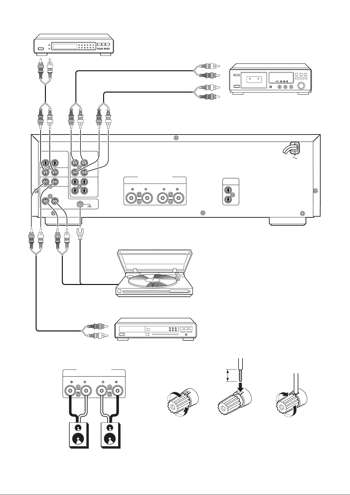
CONNECTIONS
(Figure 1)
CONNECTION OF TUNER
Connect the output jacks of your stereo tuner to the TUNER jacks of this
unit.
CONNECTION OF COMPACT DISC PLAYER
Connect the output jacks of your CD player to the CD jacks of this unit.
CONNECTION OF TURNTABLE
Connect the L (Left) output cord of the turntable to the "L" PHONO jack
of this unit, and connect the R (Right) output cord to the "R" PHONO jack.
Also be sure to connect the turntable's grounding wire to the GND jack
of this unit. The GND jack does not have to be connected if the turntable
is not provided with a grounding wire.
CONNECTION OF TAPE DECK
Connect the IN (recording input) jacks of the tape deck to the OUT jacks
of this unit, and connect the OUT (playback output) jacks of the tape
deck to the IN jacks of this unit.
CONNECTION OF SPEAKER SYSTEMS
This unit is equipped with a sets of SPEAKER SYSTEM terminals.
• The speakers in the speaker system should have an impedance
between 8 and 16 ohms. If speakers with an impedance of less than
8 ohms are connected, the protection circuitry may be activated
during play.
• Connect the Right channel speaker to the R terminals, and the Left
channel speaker to the L terminals.
• The output terminals have positive (r: Red) and negative (s: Black)
polarity, and each speaker also has the same polarity (r and s). When
connecting the speaker, be sure to connect the terminals with the
same polarity (r with r, s with s).
NOTE:
Turn the knobs on the speaker terminals by hand. (Do not use a tool
to turn the knobs.)
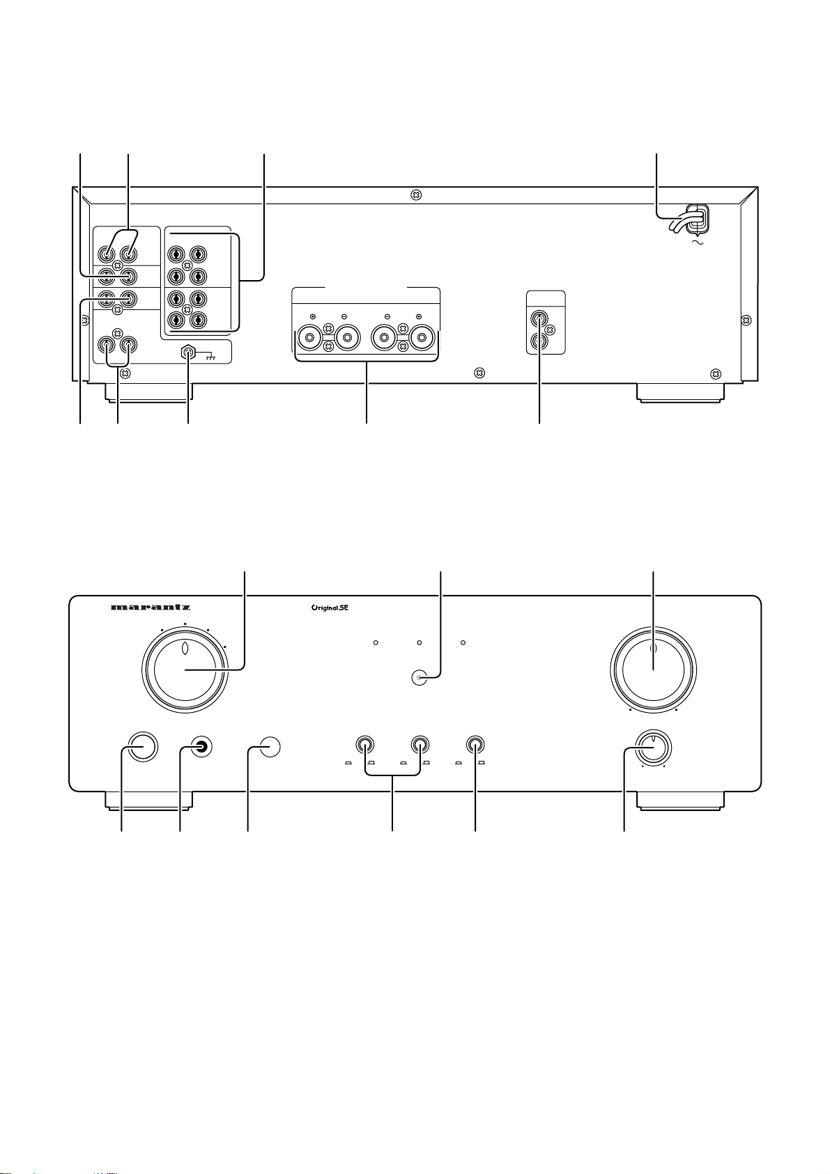
CONTROLS, CONNECTORS, AND INDICATORS
(Figure 2)
AA
AUX INPUT JACKS
A
AA
These are auxiliary input jacks which can be used to connect the audio
outputs of AV components such as TV multiplex/stereo audio tuners,
VCRs, and laserdisc players.
BB
TUNER INPUT JACKS
B
BB
Connect the output jacks of the tuner to these jacks.
CC
CD PLAYER INPUT JACKS
C
CC
Connect the output jacks of a Compact Disc player to these jacks.
English
DD
PHONO INPUT JACKS
D
DD
Connect the output jacks of a turntable to these jacks.
3
Page 2
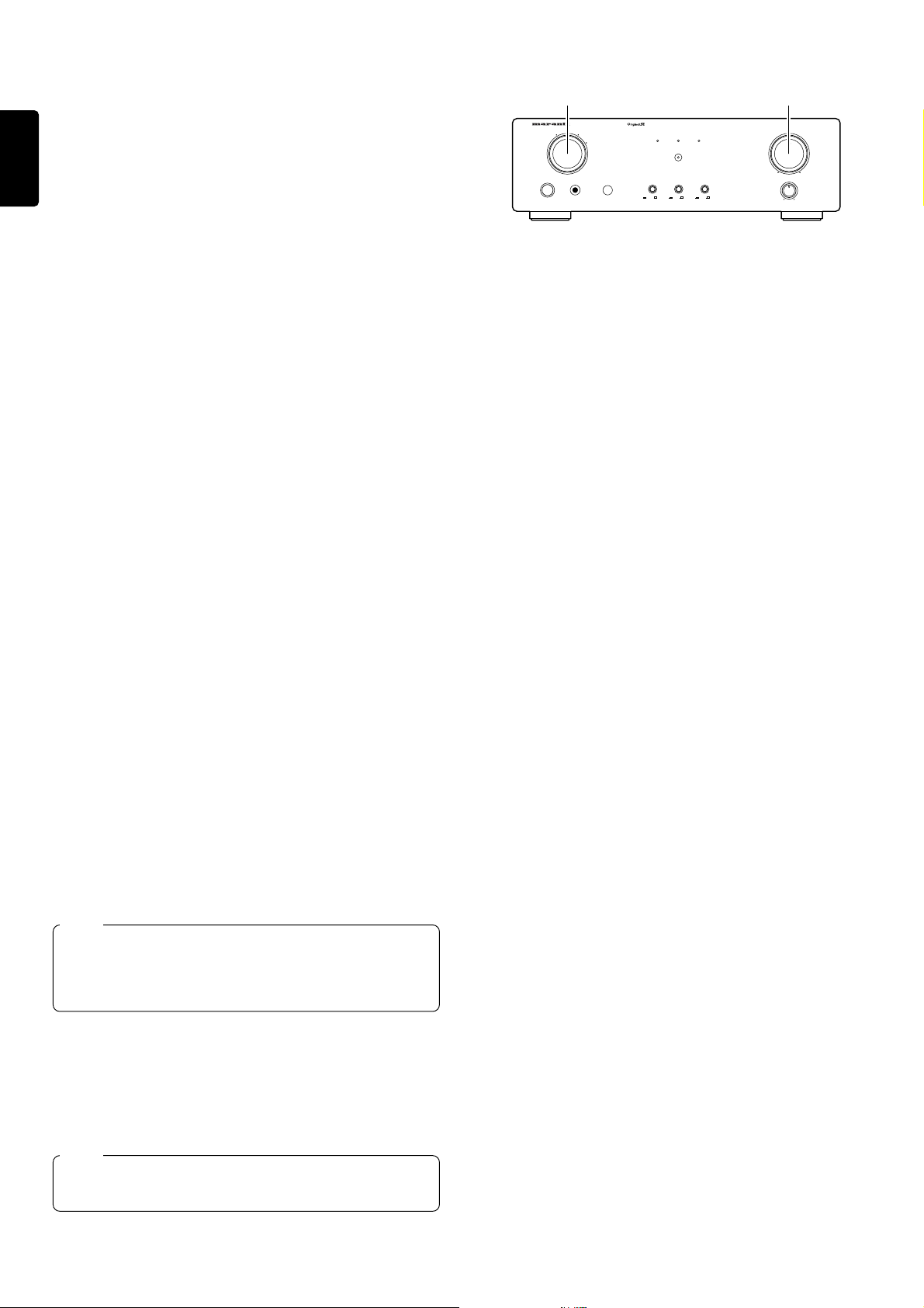
EE
TAPE CD-R/MD
SOURC E DIRECT
INTEGRATED AMPLIFIER PM6010OSE
TAPE CD-R/MD
MUTE
MIN MAX
LR
COPY
CD-R>TAPE
CD
PHONO TUNER
AUX
INPUT SELECTOR VOLUME
BALANCE
POWER ON/OFF
PHONES
ON
OFFONOFFONOFF
2 Operate each equipment to start play.
1 3
GND (GROUND) TERMINAL
E
EE
Connect the grounding wire from the turntable to this terminal.
FF
TAPE CD-R/MD IN/OUT JACKS
F
FF
Connect the play (output) jacks and record (input) jacks of tape d ecks
English
to these jacks.
Up to three tape decks can be connected.
NOTE:
When a surround processor or graphic equalizer is used, it must be
connected to the TAPE jacks.
GG
SPEAKER SYSTEMS
G
GG
Connect your speaker system to these terminals.
HH
REMOTE CONTROL (BUS) TERMINALS
H
HH
Another item of audio equipment with a remote control (bus) terminal can
be connected to these term inals by usi ng a special -purpose cable. The
bus OUT terminal is used to send sig nals t o anot her i tem of eq uip ment.
The bus IN terminal is us ed to receive si gnals from anot her item of
equipment.
II
POWER CORD
I
II
Connect to a household power outlet.
qq
POWER SWITCH
q
qq
Pressing once switches the power ON, and pressing again switches it
OFF. The POWER indicator lights when the POWER switch is ON, and
go out when the POWER switch is OFF.
ww
INPUT SELECTOR
w
ww
Selects the program source to be recorded or played from the PHONO,
CD, TUNER, AUX.
ee
VOLUME CONTROL
e
ee
Adjusts the volume level. Turn the knob clockwise to increase the
volume.
You can also operate the amplifier with a remote control unit.
rr
BALANCE CONTROL
r
rr
Turn the knob to correct an unbalanced program source such as stereo
broadcast or to vary the output level of the left or right channel.
Note that, if the BALANCE control is turned fully in one direction, the
sound will not be heard from the speaker on the other side.
OPERATION PROCEDURES
TO PLAY AN ANALOG RECORD
1. Set the INPUT SELECTOR switch to PHONO.
2. Play a record on the turntable.
3. Adjust the volume with the VOLUME control.
NOTES:
• Set the VOLUME control to the minimum position before placing the
stylus on the record or before replacing the cartridge.
• Do not apply shock or vibration to the turntable during play, as this
may cause the stylus to jump and the analog record to be damaged.
• If the turntable is installed too close to the speakers, the volume may
not be able to be increased to a high level due to howling.
• Do not switch the power OFF while the stylus is on the record surface.
TO LISTEN TO FM/AM BROADCASTS
1. Set the INPUT SELECTOR switch to TUNER.
2. Tune in the desired station on the tuner.
3. Adjust the volume with the VOLUME control.
TO PLAY A COMPACT DISC
1. Set the INPUT SELECTOR switch to CD.
2. Play a CD on the CD player.
3. Adjust the volume with the VOLUME control.
tt
TAPE CD-R/MD SWITCHES
t
tt
Press one of these switches to monitor the playback sound of a tape
deck connected to the rear panel of this unit.
When the CD-R/MD switch is pressed, this unit automatically enters the
tape dubbing mode, the COPY CD-R fi TAPE indicator lights, and the
playback signal of CD-R or MD can be copied onto tape deck.
Set both of the switches to OFF when the CD-R or MD, tape decks are
not to be played.
For details, refer to "TAPE DECK OPERATION".
yy
SOURCE DIRECT SWITCH
y
yy
When this switch is pressed, the audio signal is supplied directly to the
volume control circuitry (the signal is directed through the minimum
required path to improve the reproduction of high-quality sources).
NOTE:
When this switch is ON, the settings of the tape monitor switches,
and balance control are ignored.
While this switch is depressed, recording, playback, or dubbing of
tapes cannot be carried out even when a tape monitor switch is
pressed.
uu
IR SENSOR
u
uu
The remote sensor receives the infrared commands from the remote
control unit. When an infrared signal is received from the remote control
unit. The remote control unit must always be pointed directly at the
remote sensor.
ii
MUTING INDICATOR
i
ii
Light up when the MUTING button in the remote control unit is pressed.
NOTE:
Be sure to check the VOLUME control setting before pressing this
switch to cancel muting, If the muting is canceled while the volume
setting is high, the speakers could be damaged.
oo
PHONES JACK
o
oo
Insert the standard phone plug of the headphones into this jack.
TO PLAY A COMPONENT CONNECTED TO AUX JACKS
The component connected to the AUX jacks on the rear panel can be
played as follows.
1. Set the INPUT SELECTOR switch to AUX.
2. Play the component connected to the selected input.
3. Adjust the volume with the VOLUME control.
4
Page 3
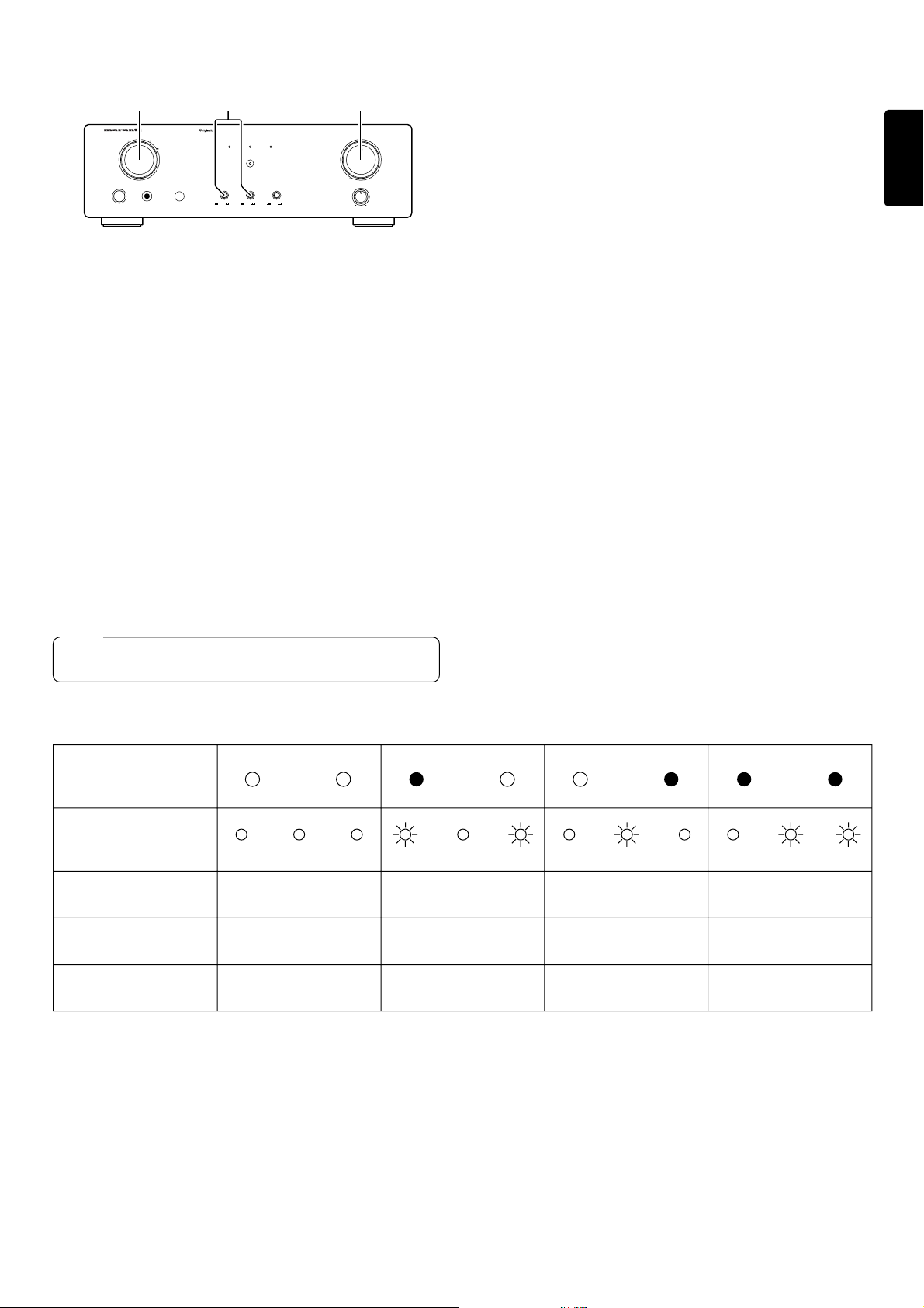
TAPE DECK (CD-R/MD) OPERATION
C B
INTEGRATED AMPLIFIER PM6010OSE
CD
PHONO TUNER
AUX
INPUT SELECTOR VOLUME
POWER ON/OFF
PHONES
Control used for operating the tape deck.
TAPE (CD-R/MD) PLAYBACK
1. Press the CD-R/MD or TAPE switch A. The indicator above the
switch will light up.
2. Play a prerecorded tape on the tape deck (or CD-R).
3. Adjust the volume with the VOLUME control B.
NOTES:
• Set the CD-R/MD TAPE switches to OFF when a tape is not to be
played.
• The tape can be played regardless of the setting of the INPUT
SELECTOR C.
TAPE RECORDING
The playback sound of a program source component, such as a
turntable, a tuner, or a CD player, can be recorded on tape as follows.
1. Set the INPUT SELECTOR switch C to select the program source to
be recorded.
2. Play the program source.
3. Operate the tape deck (or CD-R) to record the playback sound on
tape.
NOTE:
Playback and recording onto tape decks is not possible while the
SOURCE DIRECT switch is pressed in.
A
TAPE CD-R/MD
TAPE CD-R/MD
COPY
CD-R>TAPE
MUTE
SOURCE DIREC T
ON
OFFONOFFONOFF
MIN MAX
LR
BALANCE
TAPE MONITORING
When a three-head tape deck is connected to the TAPE jacks, the sound
recorded on tape can be monitored through the speakers by pressing
the TAPE monitor switch A. In this case, the tape deck must be
connected to this unit via both recording and playback connection
cords.
NOTE:
When the tape deck is a two-head system, the recorded sound cannot
be monitored even when the CD-R/MD TAPE switch A is pressed. In
this case, however, the sound of the program source being recorded
can be monitored.
When the program source selected by the INPUT SELECTOR is to be
recorded onto the tape deck connected to the TAPE jacks, do not press
the CD-R/MD switch.
If the CD-R/MD switch is pressed, the unit enters CD-R fi TAPE copy
mode.
DUBBING OF PRERECORDED TAPES
If you connect two tape decks to this unit, the contents of a prerecorded
tape can be copied onto another tape. For example, you can record only
the desired tunes on a tape containing an FM radio program onto another
tape, or you can copy the contents of an open-reel tape onto a cassette
tape. When the CD-R/MD switch is pressed, this unit automatically enter
the CD-R/MD (TAPE 2) fi TAPE (TAPE 1) copy mode, and the playback
signal of tape deck 2 can be copied onto tape deck 1.
English
TAPE MONITOR SWITCH OPERATION CHART
CD-R/MD
Switch Setting
OFF
Indicators
CD-R/MD
Speaker Output
CD-R/MD OUT Jack Output
TAPE OUT Jack Output
Source selected by INPUT
SELECTOR
Source selected by INPUT
SELECTOR
Source selected by INPUT
SELECTOR
NOTES:
• When both of the CD-R/MD and TAPE switches are pressed in. The
sound recorded from CD-R/MD to tape deck can be monitored
through the speakers.
• During dubbing, the program source selected by the INPUT SELEC-
TOR switch cannot be listened to.
TAPE
OFF
TAPE COPY
CD-R/MD
ON
CD-R/MD
Source selected by INPUT
SELECTOR
TAPE
OFF
TAPE COPY
CD-R/MD
OFF
CD-R/MD
TAPEONCD-R/MD
TAPE COPY
ON
CD-R/MD
TAPE COPY
CD-R/MD TAPE TAPE
Source selected by INPUT
SELECTOR
CD-R/MD CD-R/MD
Source selected by INPUT
SELECTOR
Source selected by INPUT
SELECTOR
• When the program source selected by the INPUT SELECTOR switch
is recorded simultaneously by the CD-R (or MD) and tape deck, the
sound recorded by CD-R or MD cannot be monitored. If the CD-R/MD
switch is pressed, the signal of CD-R/MD will be output to tape deck.
• When a component such as a surround processor or graphic
equalizer is to be used, connect the component to the TAPE IN/OUT
jacks and press the TAPE switch.
TAPE
ON
5
Page 4
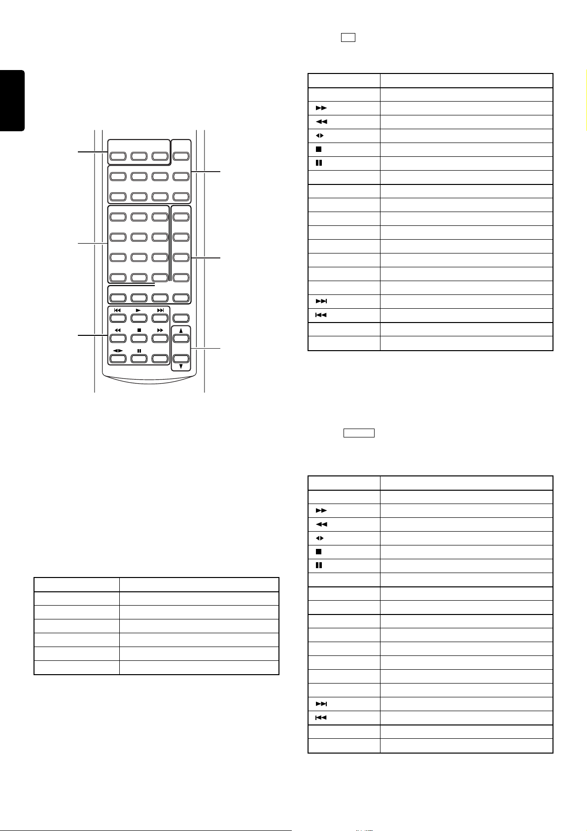
REMOTE CONTROL UNIT RC8000PM
The RC8000PM can be used to control a Marantz AV component
equipped with a remote sensor as well as other Marantz components
connected to the first component through the Remote Control Bus. The
English
buttons of the RC8000PM are laid out on its control panel according to
the functional groups as described below.
The PM6010OSE, however, can only respond to VOLUME UP/DOWN
and AUDIO MUTE/DEMUTE.
b
c
x
SYSTEM POWER
ON OFF
PHONO CD TUNER CD-R
AUX1 AUX2 TAPE MD
1 2 3 A, F/P
4 5 6 B, -/--
7 8 9 MODE
– 0 + MEMO
SCROLL CANCEL TEXT
SOURCE
ON/OFF
1–MODE–2
OPEN/
CLOSE
AMP
TIME
MUTE
VOLUME
z
v
b
When the CD button of the amplifier source selection buttons is pressed,
the remote control buttons will have the functions as listed below.
BUTTON NAME FUNCTION
PLAY Play
FF
Rewind
None
Stop
Pause
OPEN/CLOSE Open/Close
+ Next Track
– Previous Track
A, F/P Disc Select down
B, -/- - Disc Select up
MODE Automatic Music Scan (AMS)
MEMO Store Execute
TEXT (MODE 1) Text
TIME (MODE 2) Time
Next Track
Previous Track
SCROLL Scroll
CANCEL Cancel
RC8000PM
SYSTEM REMOTE CONTROLLER
zz
Group of amplifier source selection button *1
z
zz
Select the amplifier's program source.
xx
x
Group of player operation buttons
xx
Controls the CD player, cassette tape deck, etc.
cc
Group of numeric buttons
c
cc
Controls the tuner, CD player, etc., by entering numbers.
vv
Group of player/tuner auxiliary operation buttons
v
vv
Controls the mode switching and track jump operations of the tuner, CD,
etc.
bb
Group of amplifier/TV operation buttons
b
bb
Controls the power ON/OFF, volume increase/decrease, etc.
BUTTON NAME FUNCTION
SYSTEM POWER ON SYSTEM Power ON
SYSTEM POWER OFF SYSTEM Power Off
SOURCE ON/OFF Selected SOURCE POWER ON/OFF
MUTE Amp Audio Mute/Demute
VOLUME UP Amp Volume up
VOLUME DOWN Amp Volume down
*1
When an amplifier source selection button is pressed, the buttons in
groups x, c, and v become the operation buttons of the player, tuner,
TV, etc., which is selected with the amplifier source selection button.
(Except for PHONO, AMP)
The lists on the subsequent pages show the functions of the buttons in
groups x, c, and v and after each of the amplifier source selection
buttons is pressed.
When the TUNER button of the amplifier source selection buttons is
pressed, the remote control buttons will have the functions as listed
below.
BUTTON NAME FUNCTION
PLAY None
Tuning up
Tuning down
None
None
None
OPEN/CLOSE None
+ Preset up
– Preset down
A, F/P Channel/Frequency/Program
B, -/- - 1/2/3 Digits
MODE Stereo/Mono
MEMO Store Execute
TEXT (MODE 1) None
TIME (MODE 2) None
None
None
SCROLL Display
CANCEL Cancel
6
Page 5
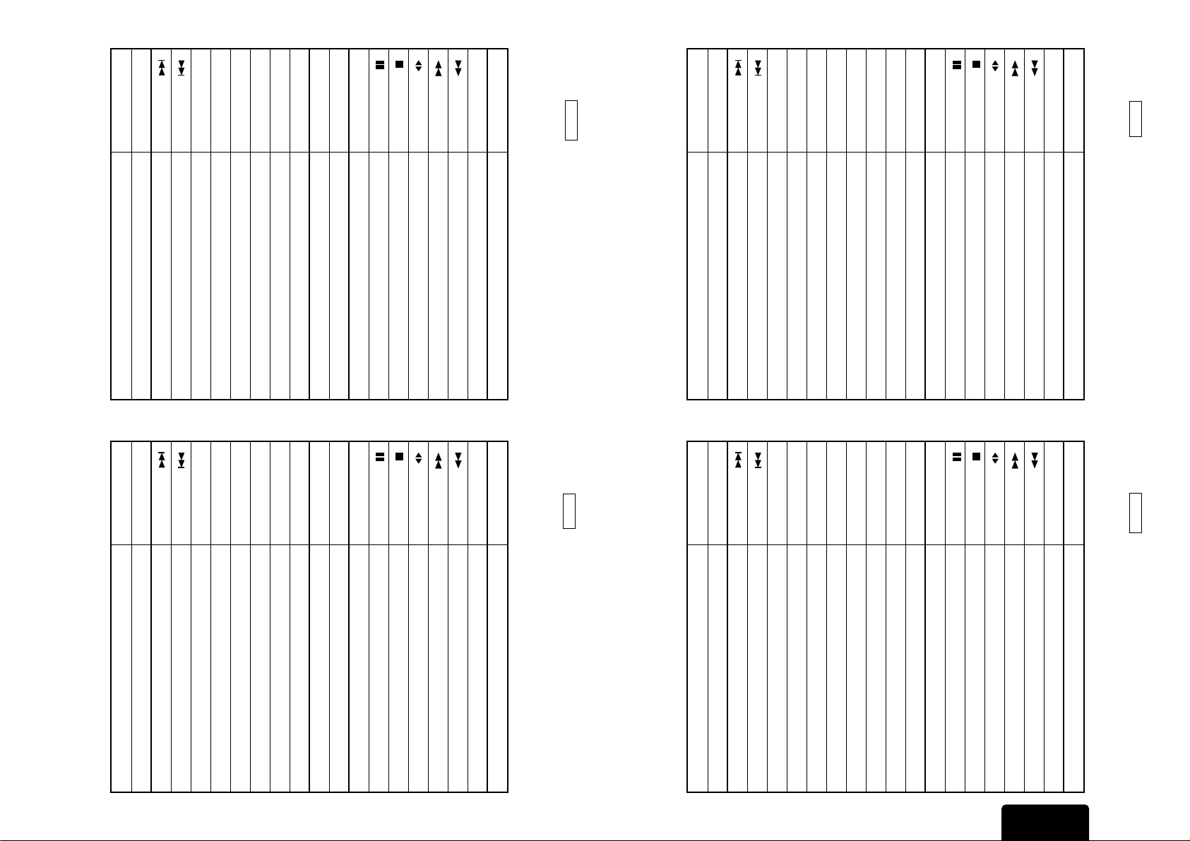
CANCEL None
SCROLL None
TEXT (MODE 1) TV Station « Text
TIME (MODE 2) Scroll Display (Time)
VCR Fast Run FWD
VCR Fast Run REV
B, -/- - 1/2/3 Digits
MODE Sound Select
MEMO Store Execute
OPEN/CLOSE VCR Eject
+ Channel/Program up
– Channel/Program down
A, F/P Channel/Frequency/Program
VCR Stop
VCR Pause
BUTTON NAME FUNCTION
PLAY VCR Play
VCR FF
VCR Rewind
VCR Play REV/Direction
below.
CANCEL Cancel
SCROLL Scroll
Next
Previous
TIME (MODE 2) Time
B, -/- - None
MODE Automatic Music Scan (AMS)
MEMO Store Execute
TEXT (MODE 1) Text
A, F/P None
+ Next
– Previous
OPEN/CLOSE Eject
Pause
Stop
None
FF
Rewind
BUTTON NAME FUNCTION
PLAY Play
When the CD-R button of the amplifier source selection buttons is
pressed, the remote control buttons will have the functions as listed
below.
When the AUX 1 button of the amplifier source selection buttons is
pressed, the remote control buttons will have the functions as listed
7
When the AUX 2 button of the amplifier source selection buttons is
pressed, the remote control buttons will have the functions as listed
CANCEL Cancel
SCROLL None
MEMO Store Execute
TEXT (MODE 1) Scroll Local Display
TIME (MODE 2) Scroll Display
OPEN/CLOSE Eject
+ Next
– Previous
A, F/P Deck A
B, -/- - Deck B
MODE Automatic Music Scan (AMS)
BUTTON NAME FUNCTION
PLAY Play
When the TAPE button of the amplifier source selection buttons is
pressed, the remote control buttons will have the functions as listed
below.
CANCEL None
SCROLL None
B, -/- - 1/2/3 Digits
MODE Sound Select
MEMO Store Execute (Memo Rew.)
TEXT (MODE 1) Text « TV Station
TIME (MODE 2) Scroll Display (Time)
+ Step up
– Step down
A, F/P Channel/Preset
OPEN/CLOSE VCR Eject
PLAY VCR Play
below.
BUTTON NAME FUNCTION
Next
Previous
Pause
Stop
Rewind
Direction
FF
VCR Fast Run FWD
VCR Fast Run REV
VCR REV/Direction
VCR Stop
VCR Pause
VCR FF
VCR Rewind
English
Page 6
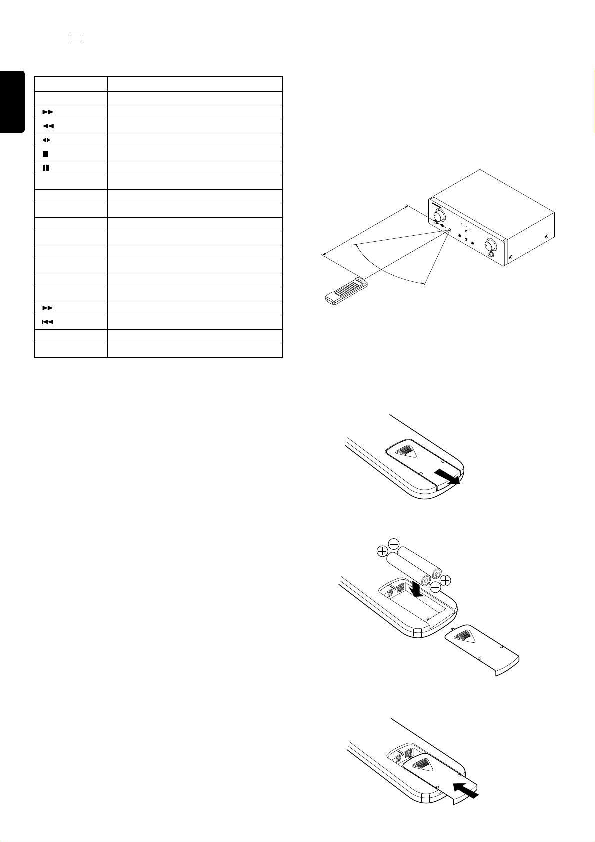
Approx. 5m
Remote control unit RC8000PM
Amplifier (PM6010OSE)
Remote control operating range
When the MD button of the amplifier source selection buttons is pressed,
the remote control buttons will have the functions as listed below.
English
BUTTON NAME FUNCTION
PLAY Play
FF
Rewind
None
Stop
Pause
OPEN/CLOSE Eject
+ Next
– Previous
A, F/P Edit
B, -/- - Enter
MODE Monitor
MEMO Program
TEXT (MODE 1) None
TIME (MODE 2) Time
Next
Previous
SCROLL Scroll
CANCEL Delete
USING THE REMOTE CONTROL UNIT
1. Remote control
Operate the remote control unit (RC8000PM) within a distance of approx.
5 m from the infrared signal reception window (remote sensor) on the
front of the Amplifier (PM6010OSE).
Remote control operation may not be possible if the remote control unit's
transmitter is not pointing in the direction of the remote sensor or if there
is an obstruction between the transmitter and the remote sensor.
Remote control operating range
2. Loading batteries
Batteries in this remote control unit have a life of approximately 1 year
under normal operating conditions. When the remote control unit is not
to be used for an extended period of time, remove the batteries. Also,
when you notice that the batteries are starting to run down, replace them
as soon as possible.
(1)Remove the battery cover
Remote control unit
(RC8000PM) Rear side
(2)Insert the batteries with correct R/S orientation.
Two AA (R6)-size
batteries
(3) Close the battery cover until it clicks shut.
8
Page 7

CARE AND MAINTENANCE
This section describes the care and maintenance tasks that must be
performed to optimize the operation of your Marantz equipment.
CLEANING OF EQUIPMENT EXTERNAL SURFACES
The exterior finish of your Amplifier will last indefinitely with proper care
and cleaning. Never use scouring pads, steel wool, scouring powders
or harsh chemical agents (e.g., lye solution), alcohol, thinners, benzine,
insecticide or other volatile substances as these will mar the finish of the
equipment. Likewise, never use cloths containing chemical substances.
If the equipment gets dirty, wipe the external surfaces with a soft, lint-free
cloth.
If the equipment becomes heavily soiled:
— dilute some washing up liquid in water, in a ratio of one part detergent
to six parts water.
— dip a soft, lint free in the solution and wring the cloth out until it is
damp.
— wipe the equipment with the damp cloth.
— dry the equipment by wiping it with a dry cloth.
REPAIRS
Only the most competent and qualified service technicians should be
allowed to service the equipment. The Marantz company and its factorytrained warranty station personnel have the knowledge and special
facilities needed for repair and calibration of this precision equipment.
After the warranty period has expired, repairs will be performed for a
charge if the equipment can be returned to normal operation.
In the event of difficulty, refer to your dealer or write directly to the nearest
location to you that is listed on the Marantz Authorized Service Station
list. If writing, please include the model and serial number of the
equipment together with a full description of what you think is abnormal
about the equipment's behavior.
TROUBLESHOOTING
In case of trouble or abnormal operation of the unit, check the following
before contacting service personnel. What may seem to be a serious
malfunction is often the result of a simple operation mistake. If the trouble
persists after checking the following, please contact your dealer or
nearest Marantz distributor.
The amplifier does not operate and the indicators do not
light.
1. Check to see if the power cord is inserted properly into the power
outlet.
The indicators light but the amplifier does not operate.
1. Check to see if the SELECTOR switches and VOLUME control are
properly set.
Sound is heard from only one of the speakers.
1. Check to see if the BALANCE control is properly set.
2. Switch the power of the unit to OFF, and change the connections of
the left and right speaker cords. If the sound from the same speaker
is still not heard, its connection cord or the speaker itself may be
defective.
Considerable hum noise is heard when the turntable is played.
1. Check to see if the plugs from the turntable are properly connected
to the PHONO jacks.
2. Connect the grounding wire of the turntable to the GND terminal on
the rear panel of this unit. If it has already been connected, try
removing it.
3. Check to make sure that the phono cartridge is attached securely to
the tone arm.
4. Unplug the power cord and plug it in again after inverting the
orientation of the blades.
English
What happens when the SOURCE DIRECT switch is pressed:
The audio signal from the program source is directed to the bypass
circuit, which sends the signal through the minimum required circuit
length to minimize signal degradation in the signal path.
Therefore, when the SOURCE DIRECT switch is pressed, the signals
from the TAPE and CD-R/MD jacks are not output to the speakers or
headphones.
To output the tape deck or CD-R (MD) signals, the SOURCE DIRECT
switch should be set to OFF.
Remote control operation is not possible.
1. Is the remote control unit's (RC8000PM) transmitter pointed correctly
at the remote sensor on the front of the Amplifier (PM6010OSE)?
Or, is there an obstruction between the transmitter and the remote
sensor?
2. Are the batteries in the remote control unit (RC8000PM) exhausted?
3. Is there another strong light (from a window, etc.) striking the
Amplifier (PM6010OSE) remote sensor?
4. Is an Audio RCA cord connected to the "REMOTE CONTROL IN" jack
on the Amplifier (PM6010OSE) rear panel?
9
Page 8

MODEL PM6010OSE TECHNICAL SPECIFICATIONS (DIN)
Power output
RMS 8 Ohms ........................................................................................................................................................... 50 W
DIN 8 Ohms ............................................................................................................................................................ 55 W
IHF dynamic power
8 Ohms ................................................................................................................................................................... 80 W
THD at 8 Ohms rated output.............................................................................................................................. 0.008 %
Intermodulation distortion .................................................................................................................................. 0.008 %
Damping factor ......................................................................................................................................................... 100
Magnetic cartridge input
Input sensitivity inpedance................................................................................................................... 2.5 mV/47 kOhm
Accuracy of frequency response to IEC RIAA ...................................................................................................... 0.5 dB
Signal to noise ratio (IHF A weighted) ................................................................................................................... 87 dB
Tuner/CD/Aux/Tape inputs
Input sensitivity impedance................................................................................................................. 150 mV/33 kOhm
Signal to noise ratio (A weighted) .......................................................................................................................... 97 dB
Frequency response (-3 dB limits).............................................................................................................. 5 Hz -70 kHz
Channel separation (1 kHz/10 kHz).................................................................................................................. 85/65 dB
General
Power Requirements ............................................................................................................................ 230 V AC, 50 Hz
Dimensions (MAX)
Width ............................................................................................................................................................ 440 mm
Height........................................................................................................................................................... 138 mm
Depth............................................................................................................................................................ 338 mm
Weight
Unit alone ......................................................................................................................................................... 6.7 kg
Specifications subject to change without prior notice.
Page 9
Tuner
Output
RL
AUX
TUNER
CD
PHONO
RL
CD-R/MD
TAPE
Output
Tape deck
Input
IN
OUT
IN
OUT
SPEAKER SYSTEM
8 – 16 OHMS
RL
REMOTE
CONTROL
IN
OUT
Output
SPEAKER SYSTEM
8 – 16 OHMS
RL
Turntable
CD player
NOTE:
Turn the knobs on the speaker terminals by hand.
(Do not use a tool to turn the knobs.)
5 mm
Loosen the terminal Inset the core
Connection of speaker cable
Figure 1
Tighten the terminal
Page 10
BA F I
RL
RL
AUX
TUNER
CD
PHONO
PHONO TUNER
CD-R/MD
INTEGRATED AMPLIFIER PM6010OSE
CD
IN
TAPE
OUT
IN
OUT
SPEAKER SYSTEM
8 – 16 OHMS
RL
REMOTE
CONTROL
IN
OUT
HGEDC
wi e
COPY
AUX
TAPE CD-R/MD
CD-R>TAPE
MUTE
INPUT SELECTOR VOLUME
POWER ON/OFF
PHONES
qo u
MIN MAX
TAPE CD-R/MD
ON
ON
OFF
OFF
SOURCE DIRECT
ON
OFF
ty r
Figure 2
LR
BALANCE
 Loading...