

Page 1
AV Preamplifier
Owner’s Manual
1
Page 2
Contents Connections Playback Settings Tips Appendix
Accessories
Inserting the batteries
Operating range of the remote control unit
Features
High quality sound
High performance
Easy operation
Part names and functions
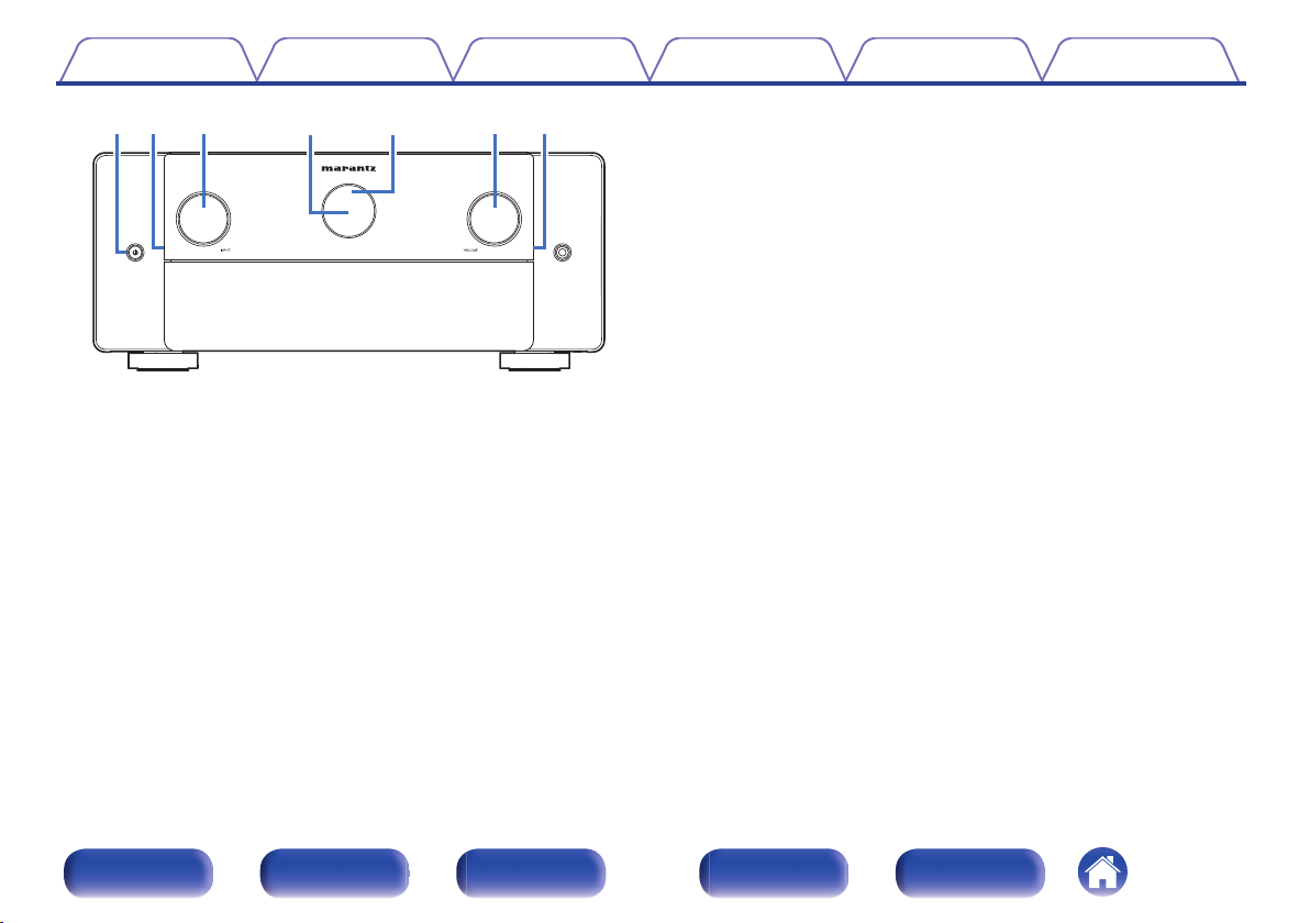
Front panel
Display
Rear panel
Remote control unit
9
Connections
10
Speaker installation
10
Connecting a power amp
11
11
15
19
20
20
25
29
33
Before connecting a power amp
Speaker configuration and “Amp Assign” settings
Connecting 5.1-channel speakers
Connecting 7.1-channel speakers
Connecting 9.1-channel speakers
Connecting 11.1-channel speakers
Connecting 13.1-channel speakers
Connecting 15.1-channel speakers
Connecting 11.1-channel speakers: Bi-amp connection of front
speakers
Connecting 11.1-channel speakers: Second pair of front speakers
37
43
43
48
50
51
53
56
59
62
63
64
Front panel Display Rear panel Remote Index
2
Page 3
Contents Connections Playback Settings Tips Appendix
Connecting a TV
Connection 1 : TV equipped with an HDMI connector and
compatible with the ARC / eARC
Connection 2 : TV equipped with an HDMI connector and
incompatible with the ARC / eARC
Connecting a playback device
Connecting a set-top box (Satellite tuner/cable TV)
Connecting a media player
Connecting a Blu-ray Disc player or DVD player
Connecting a game console or player device compatible with 8K
Connecting a turntable
Connecting a USB memory device to the USB port
Connecting FM/AM antennas
Connecting to a home network (LAN)
Wired LAN
Wireless LAN
Connecting an external control device
AMP CONTROL jacks
REMOTE CONTROL jacks
FLASHER IN jack
DC OUT jacks
Connecting the power cord
65
Playback
66
Basic operation
67
68
70
71
72
73
74
75
76
78
78
79
80
80
81
83
84
85
Turning the power on
Selecting the input source
Adjusting the volume
Turning off the sound temporarily (Muting)
Playback a Blu-ray Disc player/DVD player
Playing a USB memory device
Playing files stored on USB memory devices
Listening to music on a Bluetooth device
Playing music from Bluetooth device
Pairing with other Bluetooth devices
Reconnecting to this unit from a Bluetooth device
Listening to audio on Bluetooth headphones
Listening to audio on Bluetooth headphones
Adjusting the volume of Bluetooth headphones
Reconnecting to a Bluetooth headphones
Disconnecting Bluetooth headphones
87
87
87
88
88
88
89
90
93
94
95
96
97
98
99
99
100
Front panel Display Rear panel Remote Index
3
Page 4
Contents Connections Playback Settings Tips Appendix
Listening to FM/AM broadcasts
Listening to FM/AM broadcasts
Tuning in by entering the frequency (Direct Tune)
Changing the tune mode (Tune Mode)
Tuning in to stations and presetting them automatically (Auto
Preset Memory)
Presetting the current broadcast station (Preset Memory)
Listening to preset stations
Specify a name for the preset broadcast station (Preset Name)
Skipping preset broadcast stations (Preset Skip)
Cancelling Preset Skip
Listening to Internet Radio
Listening to Internet Radio
Playing back files stored on a PC or NAS
Playing back files stored on a PC or NAS
Getting the HEOS App
HEOS Account
Playing from streaming music services
Listening to the same music in multiple rooms
101
102
103
104
104
105
105
106
107
108
109
110
111
112
115
116
117
119
AirPlay function
Playing songs from your iPhone, iPod touch or iPad
Playing iTunes music with this unit
Play a song from your iPhone, iPod touch or iPad on multiple
synced devices (AirPlay 2)
Spotify Connect function
Playing Spotify music with this unit
Convenience functions
Playing back HEOS Favorites
Adding to HEOS Favorites
Deleting a HEOS Favorites
Adjusting the audibility of dialog and vocals (Dialog Enhancer)
Adjusting the volume of each channel to match the input source
(Channel Level Adjust)
Adjusting the tone (Tone)
Selecting a Dirac Live filter (Dirac Live)
Adjusting audio delay (Audio Delay)
Changing the strength of Tactile Transducer according to the
input source (Tactile Transducer)
Displaying your desired video during audio playback (Video
Select)
Playing the same music in all zones (All Zone Stereo)
Changing the speaker settings to match the listening environment
(Speaker Preset)
123
124
124
125
126
126
127
128
129
129
129
130
131
132
132
133
134
135
136
Front panel Display Rear panel Remote Index
4
Page 5
Contents Connections Playback Settings Tips Appendix
Selecting a sound mode
Selecting a sound mode
Direct playback
Pure Direct playback
Auto surround playback
Description of sound mode types
Sound mode that can be selected for each input signal
HDMI Control function
Setting procedure
Sleep timer function
Using the sleep timer
Smart select function
Calling up the settings
Changing the settings
Panel lock function
Disabling all key button operations
Disabling all button operations except VOLUME
Canceling the Panel lock function
137
138
139
139
140
141
146
151
151
152
153
154
155
156
158
158
159
159
Remote lock function
Disabling the sensor function of the remote control unit
Enabling the remote sensor function
Web control function
Controlling the unit from a web control
Playback in ZONE2/ZONE3 (Another room)
Connecting ZONE
Playback the source in ZONE2/ZONE3
Adjusting the Volume in ZONE2/ZONE3
Settings
Menu map
Menu operations
Audio
Subwoofer Level Adjust
Bass Sync
Surround Parameter
M-DAX
Volume
Audyssey
Dirac Live
Graphic EQ
DAC Filter
®
160
160
160
161
161
163
164
166
170
171
176
177
177
177
178
185
186
187
190
190
192
Front panel Display Rear panel Remote Index
5
Page 6
Contents Connections Playback Settings Tips Appendix
Video
HDMI Setup
Output Settings
On-Screen Display
Screensaver
4K/8K Signal Format
HDCP Setup
Inputs
Input Assign
Source Rename
Hide Sources
Source Level
Speakers
Audyssey® Setup
Procedure for speaker settings (Audyssey® Setup)
Error messages
Retrieving Audyssey® Setup settings
193
193
198
199
200
201
202
203
203
206
206
207
208
208
210
216
218
Manual Setup
Speaker Layout
Amp Assign
Front/Center/Surround/Surround Back/Front Wide
Height Speakers
Layout
Front Layout / Middle Layout / Rear Layout / TS/CH
Subwoofers
Subwoofer Mode
Subwoofer Layout
Bi-Amp
Front B
Settings
View Terminal Config.
219
219
219
220
221
222
223
228
228
229
232
232
233
233
Front panel Display Rear panel Remote Index
6
Page 7
Contents Connections Playback Settings Tips Appendix
Distances
Levels
Crossovers
Speaker Preset
Advanced
Subwoofer Output
Low Pass Filter
Distribution
Front Speaker
2ch Playback
Tactile Transducer
Dirac Live Setup
Network
Information
Connection
Wi-Fi Setup
Settings
Network Control
Friendly Name
Diagnostics
AirPlay
Spotify Connect
TIDAL Connect
Wi-Fi and Bluetooth
233
235
235
236
237
237
238
239
239
240
242
244
245
245
245
246
248
249
250
250
251
252
252
252
HEOS
You have not signed in
You have already signed in
General
Language
Owner's Manual
Bluetooth Transmitter
ZONE2 Setup / ZONE3 Setup
Zone Rename
Smart Select
Trigger Out 1 / Trigger Out 2 / Trigger Out 3
Auto Standby
Front Panel
Firmware
Information
Usage Data
Save & Load
Setup Lock
Reset
Setting the back light of the remote control unit
Disabling the backlight
Specifying the zone used with the remote control unit
253
253
253
254
254
254
254
255
258
258
259
260
261
262
264
266
266
267
267
268
268
269
Front panel Display Rear panel Remote Index
7
Page 8
Contents Connections Playback Settings Tips Appendix
Tips
Tips
Troubleshooting
Power does not turn on / Power is turned off
Operations cannot be performed through the remote control unit
Display on this unit shows nothing
No sound comes out
Desired sound does not come out
Sound is interrupted or noise occurs
No video is shown on the TV
The menu screen is not displayed on the TV
The color of the menu screen and operations content displayed
on the television is different from normal
AirPlay cannot be played back
USB memory devices cannot be played back
Bluetooth cannot be played back
The Internet radio cannot be played back
Music files on PC or NAS cannot be played back
Various online services cannot be played
The HDMI Control function does not work
Cannot connect to a wireless LAN network
When using HDMI ZONE2, the devices does not function properly
Update error messages
271
273
274
275
275
276
277
281
282
284
284
285
286
287
289
290
291
291
292
293
294
Resetting factory settings
Resetting network settings
Factory Restore
Appendix
About HDMI
Video conversion function
Playing back a USB memory devices
Playing back a Bluetooth device
Playing back a file saved on a PC or NAS
Playing back Internet Radio
Personal memory plus function
Last function memory
Sound modes and channel output
Sound modes and surround parameters
Types of input signals, and corresponding sound modes
Explanation of terms
Trademark information
Specifications
Audio section
Video section
Tuner section
Wireless LAN section
Bluetooth section
General
Index
295
296
297
298
302
304
305
306
307
307
307
308
310
313
316
327
331
331
332
333
333
334
335
337
Front panel Display Rear panel Remote Index
8
Page 9
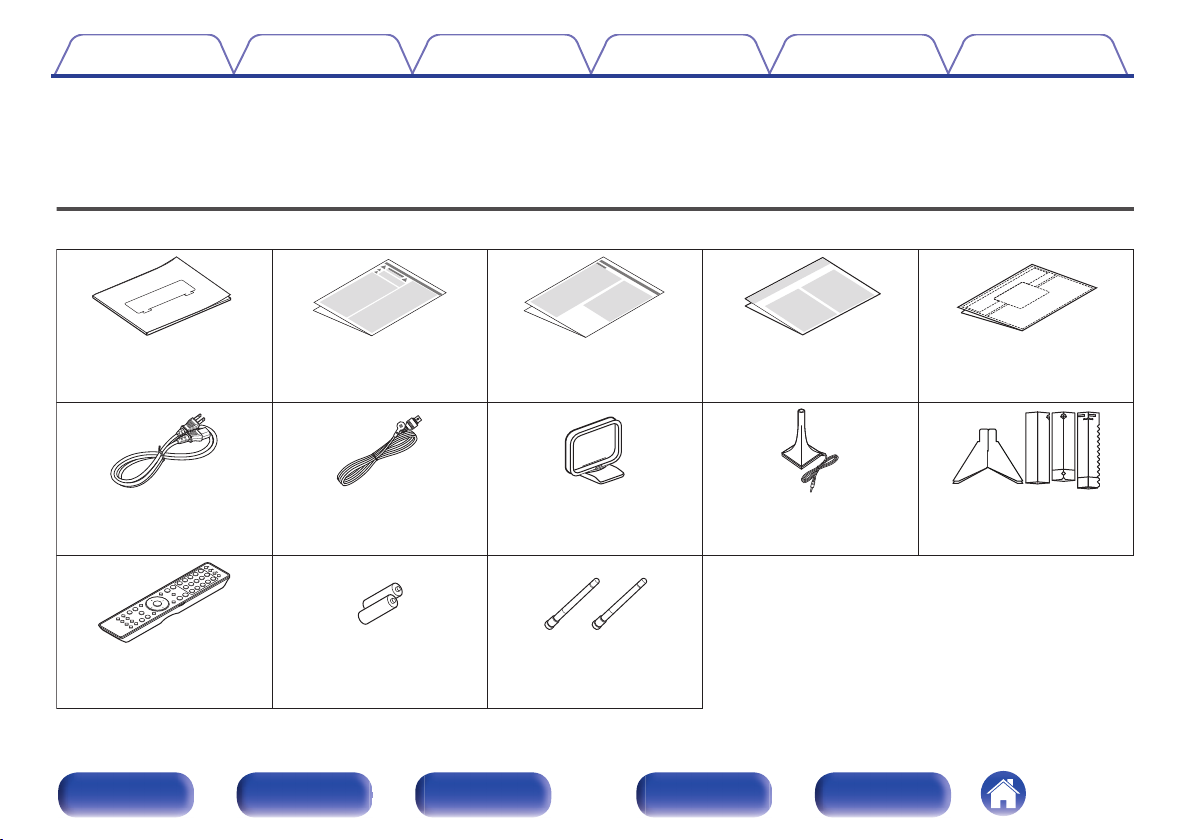
Cable labelsWarranty
(for North America model
only)
Notes on radioSafety InstructionsQuick Start Guide
Sound calibration
microphone stand
Sound calibration
microphone
AM loop antennaFM indoor antennaPower cord
External antennas for
Bluetooth/wireless
connectivity
Remote control unit
(RC051SR)
2× R03/AAA batteries
Contents Connections Playback Settings Tips Appendix
Thank you for purchasing this Marantz product.
To ensure proper operation, please read this owner’s manual carefully before using the product.
After reading this manual, be sure to keep it for future reference.
Accessories
Check that the following parts are supplied with the product.
Front panel Display Rear panel Remote Index
9
Page 10
Batteries
30°
Approx. 23 ft/7 m
30°
Contents
Connections Playback Settings Tips Appendix
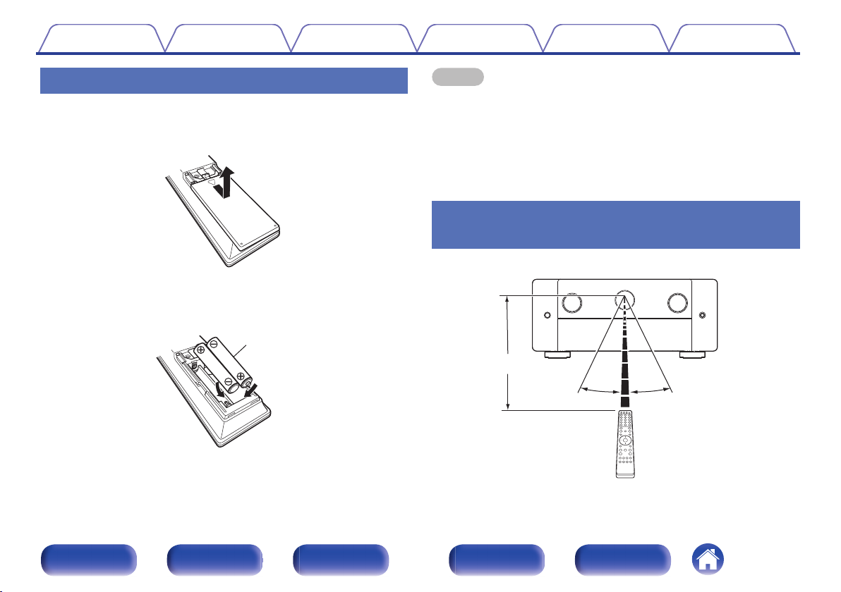
Inserting the batteries
Remove the rear lid in the direction of the arrow and
1
remove it.
Insert two batteries correctly into the battery
2
compartment as indicated.
3
Put the rear cover back on.
NOTE
To prevent damage or leakage of battery fluid:
0
Do not use a new battery together with an old one.
0
Do not use two different types of batteries.
0
Remove the batteries from the remote control unit if it will not be in use for long
0
periods.
If the battery fluid should leak, carefully wipe the fluid off the inside of the battery
0
compartment and insert new batteries.
Operating range of the remote control
unit
Point the remote control unit at the remote sensor when operating it.
Front panel Display Rear panel Remote Index
10
Page 11
Contents
Connections Playback Settings Tips Appendix
Features
High quality sound
13.4-channel processing with 15.4-channel XLR/RCA pre-outs
0
Experience a versatile home theater setup with the new processor/
preamplifier. Featuring 13.4-channel processing capability with 15.4channel XLR and RCA pre-outs, this unit works with most demanding
home theater gear up to 7.4.6 or 9.4.4 speaker configurations. Enjoy the
audiophile quality sound you expect from Marantz.
Discrete 4 subwoofers
0
Immerse yourself in evenly distributed, accurate bass. Featuring up to
four subwoofer outputs to smooth out low frequencies and provide
better dispersion. No audible peaks or dips - just powerful, room-filling
bass.
Current feedback amplifier
0
This unit uses a high-speed current feedback amplifier circuit for its
preamplifier so that signals from a Blu-ray Disc player and other
equipment that support high-definition audio formats can be amplified
with high fidelity. The high-speed current feedback amplifier also
reproduces a natural sound space.
Dolby Atmos (v p. 318)
0
This unit is equipped with a decoder that supports Dolby Atmos audio
format. The placement or movement of sound is accurately reproduced
by the addition of overhead speakers, enabling you to experience an
incredibly natural and realistic surround sound field.
Speaker Virtualizer (v p. 180)
0
Speaker Virtualizer enables you to access a more immersive
entertainment experience from traditional channel based speaker
layouts through digital signal processing including Dolby Atmos height
virtualization and surround virtualization.
Speaker Virtualizer is not for use when both height speakers and surround
0
speakers are connected.
Height Virtualization may be applied when surround speakers are connected.
0
DTS:X Pro
0
This unit is equipped with the DTS:X Pro decoder technology. DTS:X
Pro decoder brings the home theater experience to new heights with its
immersive object based audio technology which removes the bounds of
channels. Enjoy up to 13.1-channels of audio processing with DTS:X
Pro to enjoy a full surround sound in exquisite detail.
DTS Virtual:X (v p. 321)
0
DTS Virtual:X technology features DTS’s proprietary virtual height and
virtual surround processing to deliver an immersive sound experience
from any type of input source (stereo to 7.1.4 channel) and speaker
configuration.
DTS Virtual:X is not for use when Height speakers are connected.
0
Front panel Display Rear panel Remote Index
11
Page 12
Contents Connections Playback Settings Tips Appendix
IMAX Enhanced (v p. 321)
0
This IMAX Enhanced product have met stringent performance
standards established by IMAX and DTS in order to create a consistent
and higher bar for sound performance. DTS has developed a special
method for reproducing an IMAX signature sound experience in the
consumer’s home. This method combines a unique conversion process
for IMAX theatrical audio mixes utilizing an enhanced DTS codec
technology. The IMAX theatrical audio format with point source
surround speakers closely matches the speaker configuration most
consumers have in their homes today. Coupled with DTS audio
technology, IMAX Enhanced audio products will ensure the best and
most accurate audio reproduction over 5.1 or more speaker channels.
Audyssey LFC™ (Low Frequency Containment) (v p. 189)
0
Audyssey LFC™ solves the problem of low frequency sounds
disturbing people in neighboring rooms or apartments. Audyssey LFC™
dynamically monitors the audio content and removes the low
frequencies that pass through walls, floors and ceilings. It then applies
psychoacoustic processing to restore the perception of low bass for
listeners in the room. The result is great sound that no longer disturbs
the neighbors.
Discrete subwoofers and Audyssey Sub EQ HT™ (v p. 209)
0
The unit has four subwoofer output capability and can adjust the level
and delay for each subwoofer individually.
Audyssey Sub EQ HT™ makes the integration seamless by first
compensating for any level and delay differences between the four
subwoofers and then applying Audyssey MultEQ® XT32 to four
subwoofers together for improved deep bass response and detail.
Front panel Display Rear panel Remote Index
12
Page 13
Contents
Dirac Live Upgradability
0
The interaction between your sound system and the physical layout of
your room has a huge impact on sound quality. Dirac Live® Room
Correction applies state-of-the-art, patented algorithms to analyze and
digitally reduce room impact and enhance speaker performance. Dirac
Live delivers a larger sweet spot, accurate staging, clarity, voice
intelligibility, and a deeper, tighter bass not otherwise possible. Fully
tunable to your preference.
You can purchase a Dirac Live license key to unlock the functionality.
Visit www.dirac.com/marantz/
Dirac Live Bass Control Upgradability
0
Dirac Live Bass Control is a technology to manage low-frequency
channel routing from the signal to the playback channels (speakers) of
your audio device. Additionally, with full control over the device’s
channel and frequency routing and output, the Dirac Live Room
Correction technology is significantly augmented. In particular systems
with multiple subwoofers will see a substantially improved room
correction and bass performance.
For details, please refer to Dirac Live Manual.
https://manuals.marantz.com/DiracLive/ALL/EN
Connections Playback Settings Tips Appendix
Front panel Display Rear panel Remote Index
13
Page 14
FHL FHR
SHL
SHR
TS
FL FR
SW
SL SR
C
Contents Connections Playback Settings Tips Appendix
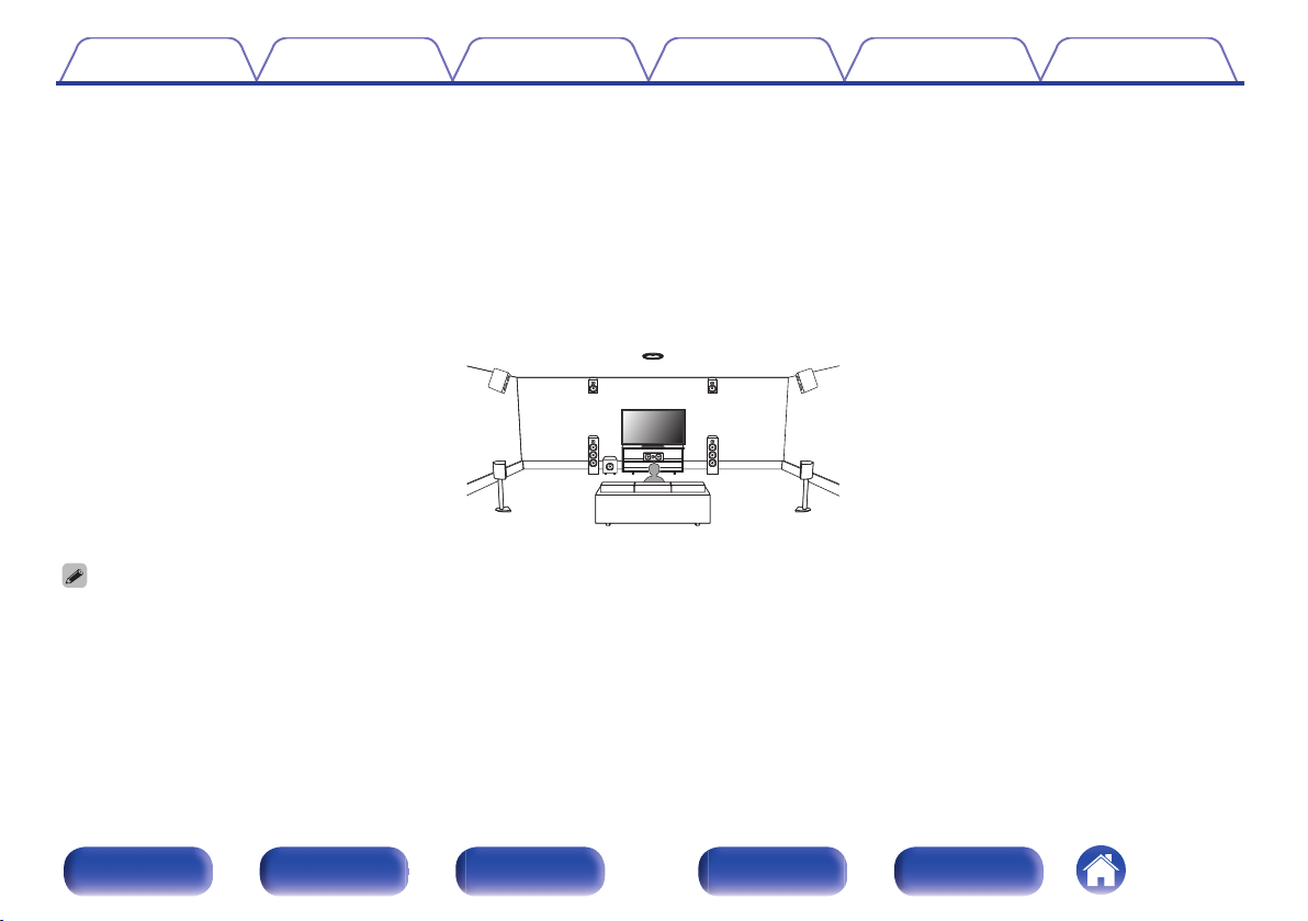
AURO-3D
0
This unit is equipped with an AURO-3D decoder.
With AURO-3D, Front Height (FHL + FHR), Surround Height (SHL + SHR) and Top Surround (TS/optional) are added to a conventional 5.1-channel
system to achieve a natural and realistic sound field that is three-dimensional and fully immersive.
You will be able to fully enjoy AURO-3D playback if you properly place the speakers for AURO-3D.
2 AURO-3D playback
AURO-3D recommends adding FRONT HEIGHT and SURROUND HEIGHT speakers to a 5.1 speaker configuration. Optionally, you may substitute REAR HEIGHT, ceiling
0
speakers, Dolby Atmos Enabled speakers instead of FRONT HEIGHT and SURROUND HEIGHT speakers for Dolby Atmos, DTS:X and AURO-3D playback.
Front panel Display Rear panel Remote Index
14
Page 15
8K,
4K 120Hz
8K,
4K 120Hz
8K Ultra HD
8K 8K
1080p/4K 60Hz
8K
up scaling
Contents
Connections Playback Settings Tips Appendix
High performance
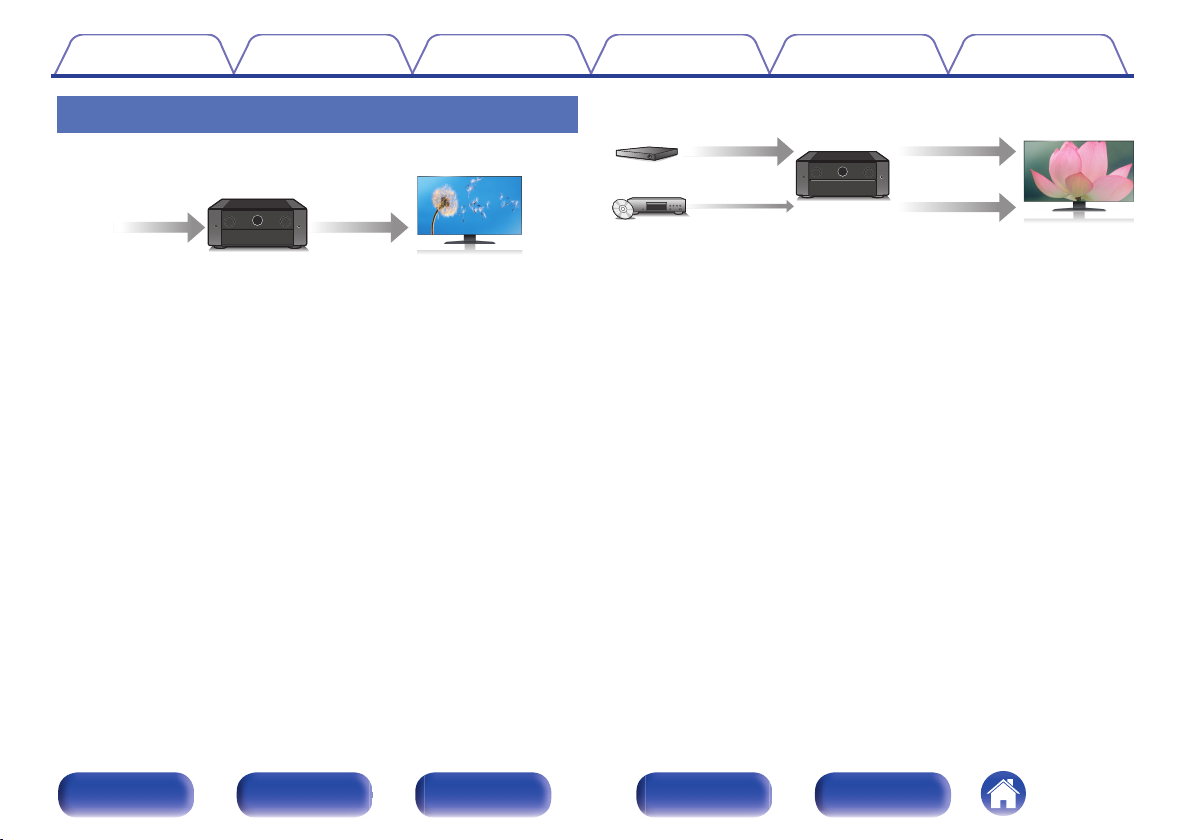
8K 60Hz input/output supported
0
When 8K Ultra HD (High Definition) is used, an input/output speed of 60
frames per second (60p) is achieved for video signals. When connected
to 8K Ultra HD and 60p video signal input compatible TV, you can enjoy
the sense of realism only available from high-definition images, even
when viewing fast-moving video.
This unit supports a wide range of HDR content, delivering even higher
definition video.
HDCP 2.3
0
This unit is compatible with HDCP 2.3 copyright protection standard.
Digital video processor upscales 1080p / 4K to 8K
0
This unit is equipped with a 8K video upscaling function that allows
1080p/4K video to be output via HDMI at 8K (7680 × 4320 pixels)
resolution. This function enables the device to be connected to a TV
using a single HDMI cable, and produces high definition images for any
video source.
eARC (Enhanced Audio Return Channel) function compatibility
0
The eARC function is compatible with conventional ARC functioncompatible audio formats in addition to multichannel linear PCM, Dolby
TrueHD, Dolby Atmos, DTS-HD, DTS:X and other audio formats a
conventional ARC function cannot transmit.
Additionally, connecting to an eARC function-compatible television
enables enjoyment of higher-quality surround playback of the audio
content played from your television.
Equipped with HDMI ZONE2 output (v p. 163)
0
The ZONE2 multi-room output includes an HDMI output that lets you
enjoy a different A/V source in that room, with another program playing
in the main room.
Front panel Display Rear panel Remote Index
15
Page 16
73
OutIn
Contents
Connections Playback Settings Tips Appendix
HDMI connections enable connection to various digital AV
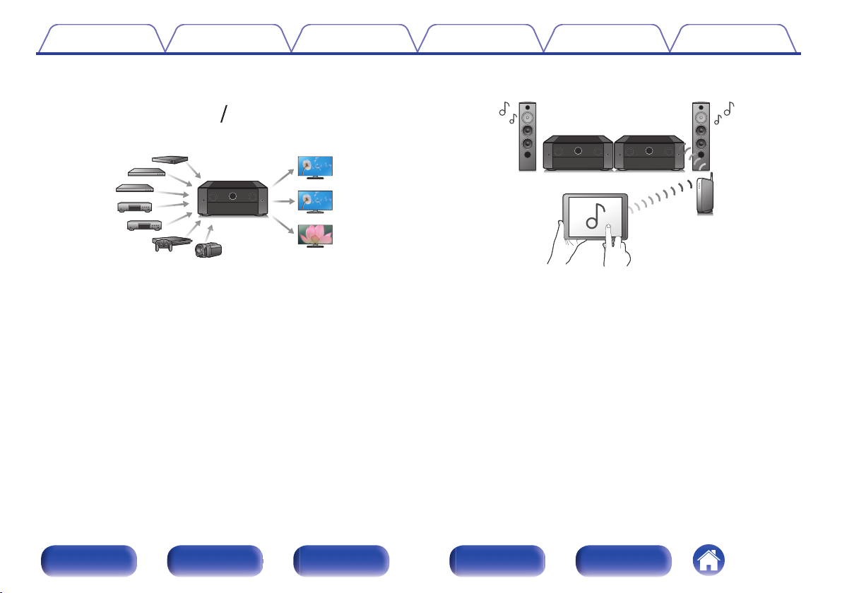
0
devices (7 inputs, 3 outputs)
For connection to a broad range of digital sources, this unit features 7
HDMI inputs, that lets you quickly and conveniently connect a
camcorder, game console or other HDMI-equipped device. There are
dual HDMI outputs for the main room, and a third HDMI output for
ZONE2.
0
The device is equipped with a AirPlay® function in addition to
network functions such as Internet radio etc. (v p. 123)
You can enjoy a wide variety of content, including listening to Internet
Radio, playing audio files stored on your PC.
This unit also supports Apple AirPlay which lets you stream your music
library from an iPhone®, iPad®, iPod touch® or iTunes®.
0
Supports AirPlay 2® wireless audio
Sync multiple AirPlay 2 compatible devices/speakers for simultaneous
playback.
This unit supports AirPlay 2 and requires iOS 11.4 or later.
Front panel Display Rear panel Remote Index
16
Page 17
Contents Connections Playback Settings Tips Appendix
Playback of DSD and FLAC files via USB and networks
0
This unit supports the playback of high resolution audio formats such as
DSD (5.6 MHz) and FLAC 192 kHz files. It provides high quality
playback of high resolution files.
Wireless connection with Bluetooth devices can be carried out
0
easily (v p. 93)
You can enjoy music simply by connecting wirelessly with your
smartphone, tablet, PC, etc.
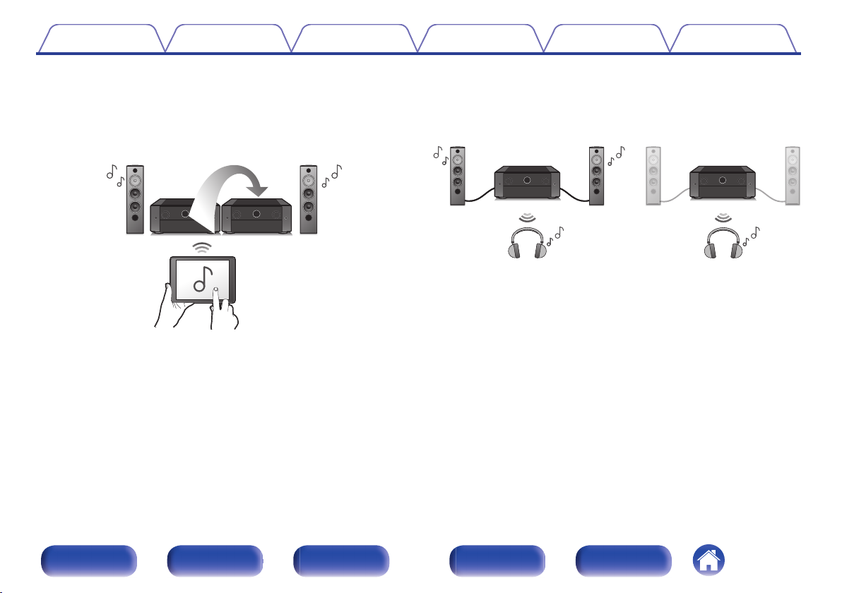
Connect Bluetooth headphones
0
This unit can transmit Bluetooth so you can enjoy audio wirelessly
through your Bluetooth headphones.
Playback can be performed using connected speakers and Bluetooth
headphones simultaneously, or only using Bluetooth headphones.
Front panel Display Rear panel Remote Index
17
Page 18
【MAIN ZONE】【ZONE2】/【ZONE3】
Contents
Connections Playback Settings Tips Appendix
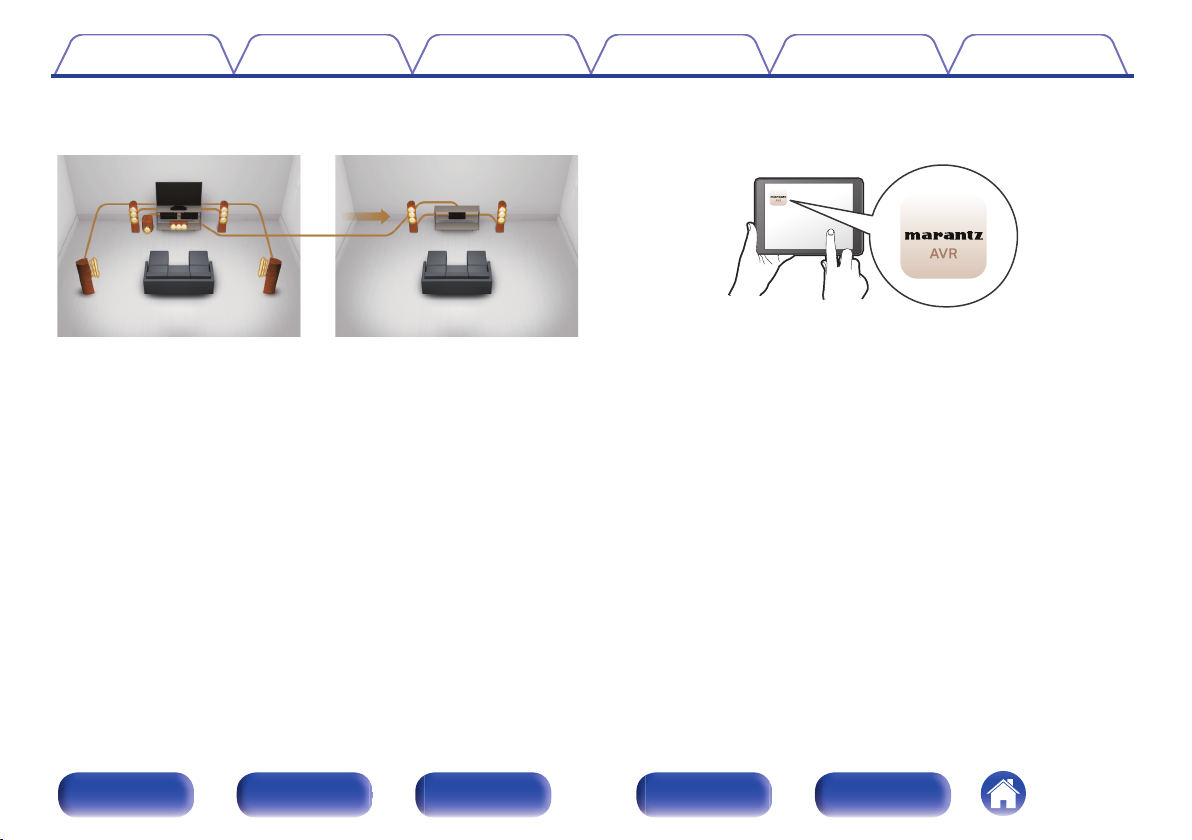
Multi-Room audio (v p. 135)
0
You can select and play back the respective inputs in MAIN ZONE,
ZONE2 and ZONE3.
In addition, when the All Zone Stereo function is used, the music being
played back in MAIN ZONE can be enjoyed in all the zones at the same
time. This is useful when you want to let the background music
propagate throughout the whole house.
Energy-saving design
0
This unit is equipped with an auto-standby function that automatically
turns off the power supply when the unit is not in use. This helps reduce
unnecessary power use.
0
Compatible with the “Marantz AVR Remote” Appz for performing
basic operations of the unit with an iPad, iPhone or Android™
devices (Google, Amazon Kindle Fire)
The Marantz AVR Remote app gives you full control of this unit as well
as access to its setup menu for detailed adjustments from your phones
or tablets. “Marantz AVR Remote” App also gives you quick access to
the receiver's status display, option menus, Marantz Blu-ray Disc player
control, and online owner's manual for your convenience.
Download the appropriate “Marantz AVR Remote” App for your iOS or Android
z
devices. This unit needs to be connected to the same LAN or Wi-Fi (wireless
LAN) network that the iPad, iPhone or Android™ is connected to.
Front panel Display Rear panel Remote Index
18
Page 19
Contents Connections Playback Settings Tips Appendix
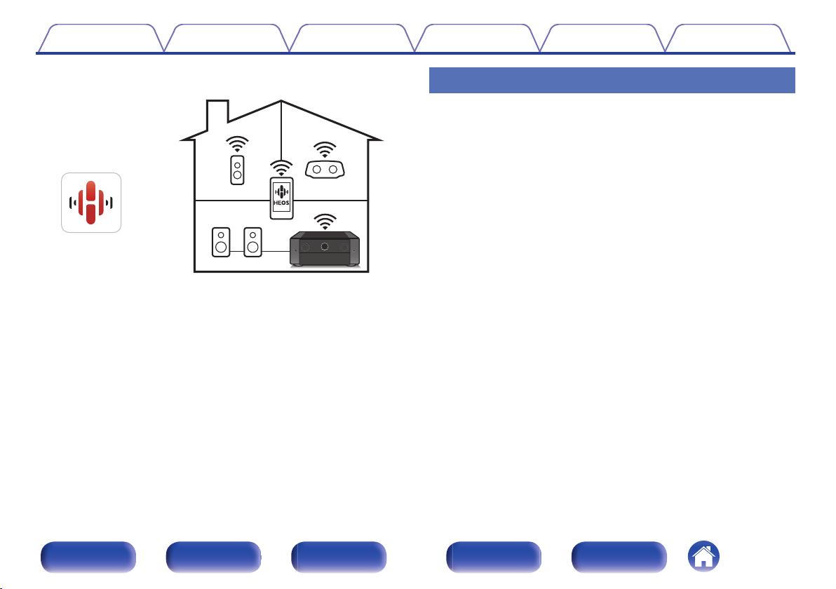
HEOS provides streaming music from your favorite online music
0
sources
HEOS wireless multi-room sound system that enables you to enjoy your
favorite music anywhere and everywhere around your home. By utilizing
your existing home network and the HEOS App (available for iOS,
Android and Amazon devices), you can explore, browse, and play
music from your own music library or from many online streaming music
services.
When multiple products with HEOS Built-in are connected to the same
network, they can be grouped to play the same music on all products
simultaneously, or different music can be played on each one.
Easy operation
“Setup Assistant” provides easy-to-follow setup instructions
0
First select the language when prompted. Then simply follow the
instructions displayed on the TV screen to set up the speakers, network,
etc.
Easy to use Graphical User Interface
0
This unit is equipped with a Graphical User Interface for improved
operability.
Front panel Display Rear panel Remote Index
19
Page 20
eq yr tw w u
i
Contents
Connections Playback Settings Tips Appendix
Part names and functions
Front panel
For details, see the next page.
Front panel Display Rear panel Remote Index
20
Page 21
e yw wqtr
Contents Connections Playback Settings Tips Appendix
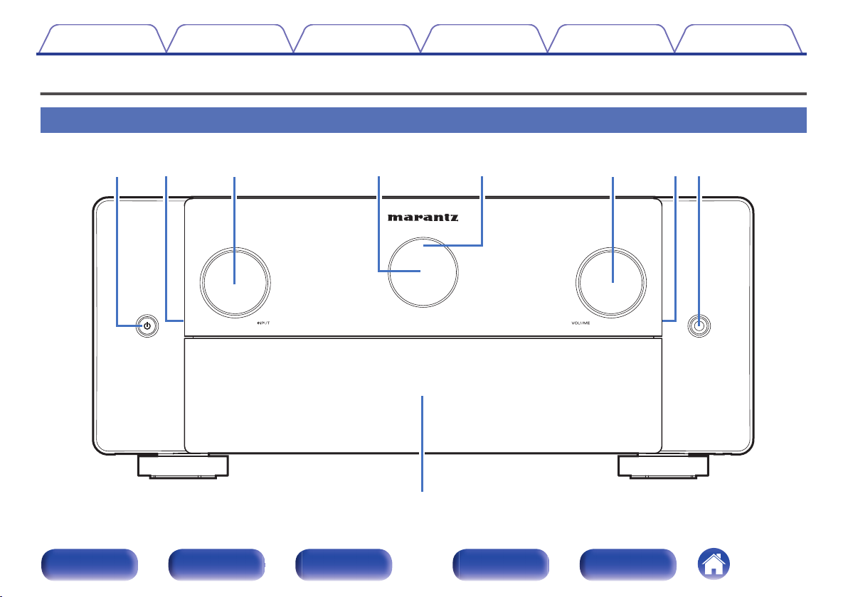
INPUT selector knob
C
This selects the input source. (v p. 87)
Main display
D
This displays various pieces of information. (v p. 25)
Remote control sensor
E
This receives signals from the remote control unit. (v p. 10)
VOLUME knob
F
This adjusts the volume level. (v p. 88)
Power operation button (X)
A
Used to turn the power of the MAIN ZONE (room where this unit is
located) on/off (standby). (v p. 87)
Illumination
B
This lights up when the power is turned on. If you press the DIMMER
button, the brightness of the illumination is switched in conjunction with
the brightness of the display.
The illumination turned off from “Front Panel” of the settings menu.
(v p. 261)
Front panel Display Rear panel Remote Index
21
Page 22
u
i
Contents Connections Playback Settings Tips Appendix
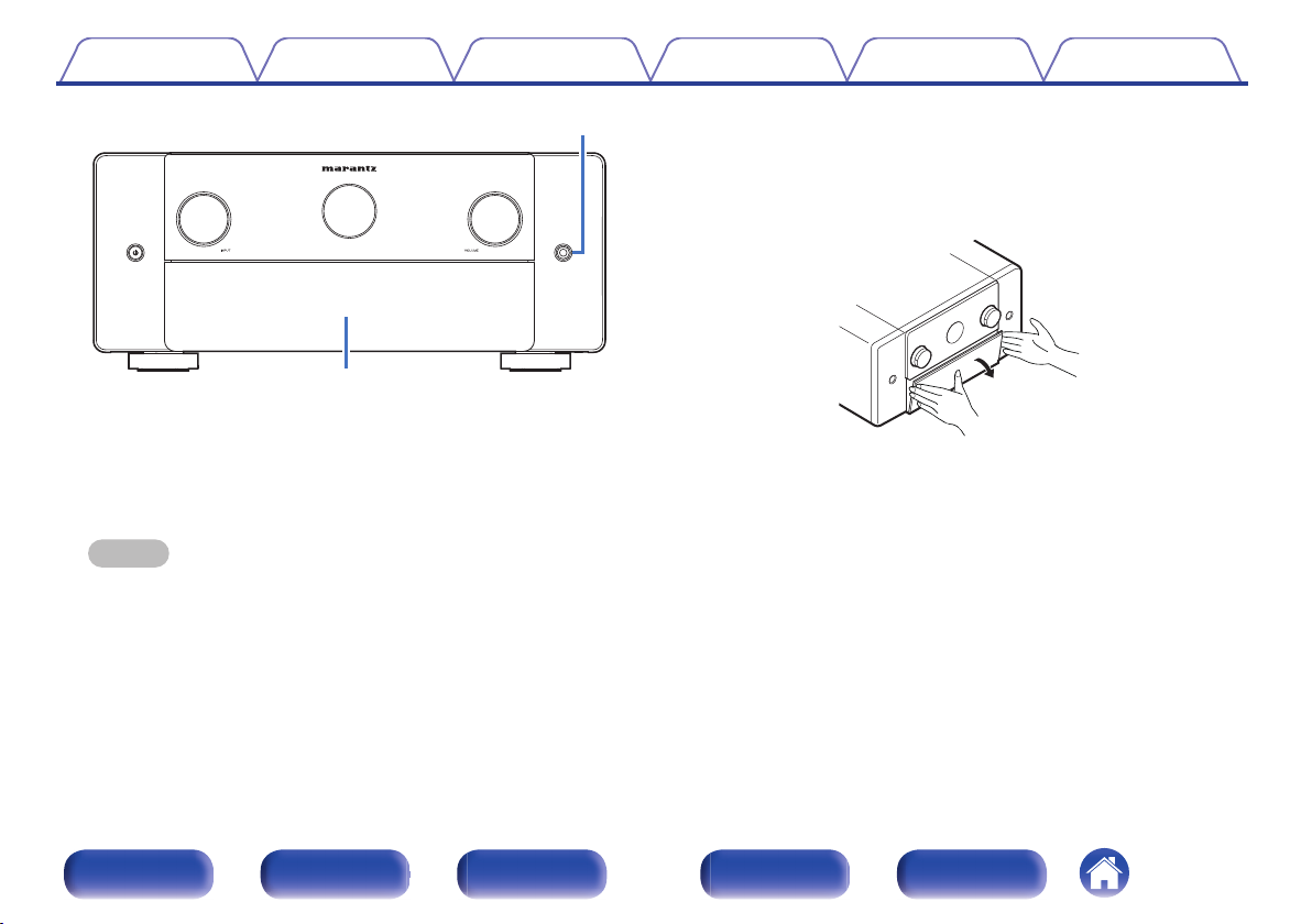
Door
H
When using the buttons and/or terminals behind the door, pull both
sides of the door towards you to open it. Be careful not to catch your
fingers when closing the door.
Headphones jack
G
This is used to connect headphones.
When the headphones are plugged into this jack, audio will no longer
be output from the connected speakers or from the PRE OUT
connectors.
NOTE
To prevent hearing loss, do not raise the volume level excessively when using
0
headphones.
Front panel Display Rear panel Remote Index
22
Page 23
y ou i
q w e r t
Contents Connections Playback Settings Tips Appendix
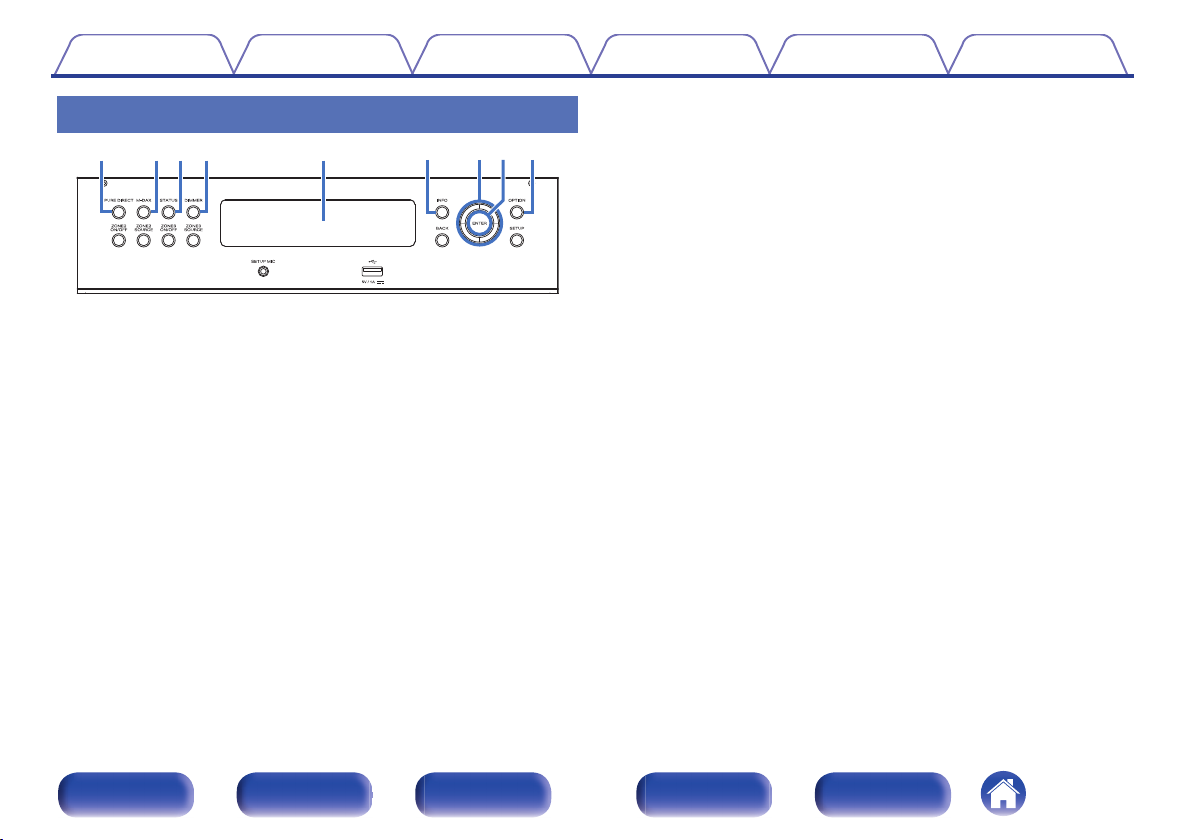
DIMMER button
With the door open
PURE DIRECT button
A
This switches the sound mode between Direct, Pure Direct and Auto.
(v p. 139 – 140)
M-DAX button
B
This enables the M-DAX mode. (v p. 185)
STATUS button
C
Each press of this switches the status information that is shown on the
display.
D
Each press of this switches the brightness of the display. (v p. 261)
Sub display
E
This displays various pieces of information. (v p. 27)
Information button (INFO)
F
This displays the status information on the TV screen. (v p. 265)
Cursor buttons
G
These select items.
ENTER button
H
This determines the selection.
OPTION button
I
This displays the option menu on the TV screen.
Front panel Display Rear panel Remote Index
23
Page 24
Q0 Q1 Q2 Q3 Q6 Q7Q4
Q5
Contents Connections Playback Settings Tips Appendix
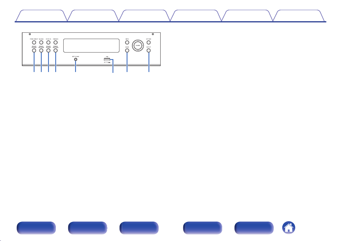
SETUP MIC jack
N
This is used to connect the supplied Sound calibration microphone.
(v p. 211)
USB port (T)
O
This is used to connect USB storages (such as USB memory devices).
(v p. 75)
BACK button
P
This returns to the previous screen.
SETUP button
ZONE2 ON/OFF button
J
This turns the power of ZONE2 (another room) on/off. (v p. 166)
ZONE2 SOURCE button
K
This selects the input source for ZONE2. (v p. 166)
ZONE3 ON/OFF button
L
This turns the power of ZONE3 (another room) on/off. (v p. 166)
ZONE3 SOURCE button
M
This selects the input source for ZONE3. (v p. 166)
Q
This displays the menu on the TV screen. (v p. 176)
Front panel Display Rear panel Remote Index
24
Page 25
B l u - r a y
0.0
SLEEP
ZONE2/3
e rq
w
Contents Connections Playback Settings Tips Appendix
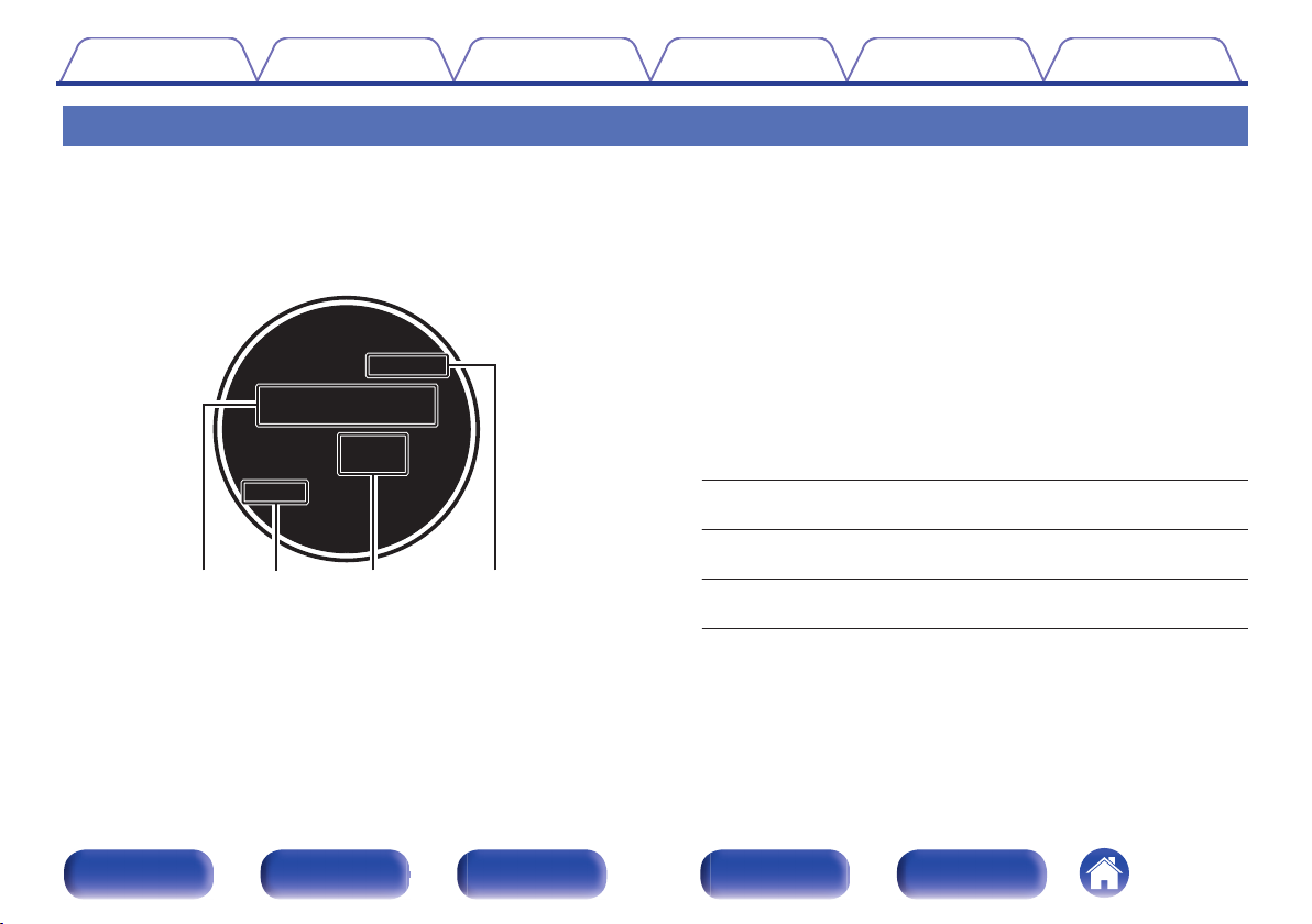
Display
o
Main display
The input source name, sound mode, setting values and other information are displayed here.
n
Standard display
Input source indicator
A
The currently selected input source name is displayed.
If the input source name has been changed using “Source Rename” in
the menu, the input source name after the change is displayed.
(v p. 206)
Sleep timer indicator
B
This lights when the sleep mode is selected. (v p. 152)
Volume indicator
C
ZONE2/ZONE3 power on display
D
ZONE2:
ZONE3:
ZONE2/3:
Lights up when ZONE2 power is turned
on.
Lights up when ZONE3 power is turned
on.
Lights up when ZONE2 and ZONE3
power is turned on. (v p. 168)
Front panel Display Rear panel Remote Index
25
Page 26
01 FM
92 . 10MHz
TUNED
ST
t
y
Contents Connections Playback Settings Tips Appendix
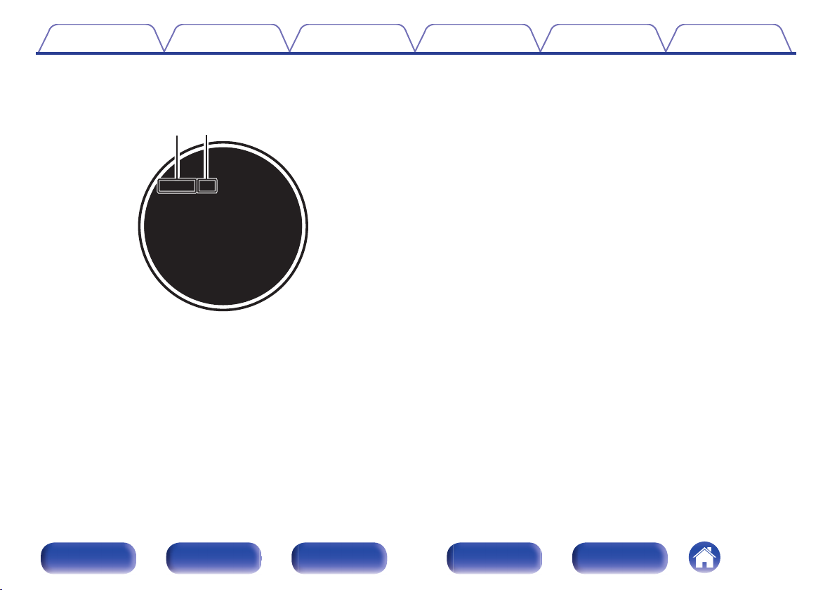
n
Tuner display
These light up according to the reception conditions when the input
source is set to “Tuner”.
Lights up when the broadcast is properly tuned in.
E
Lights up when receiving FM stereo broadcasts.
F
Front panel Display Rear panel Remote Index
26
Page 27
Q0 Q1 Q2
iuoyt
rewq
Contents Connections Playback Settings Tips Appendix
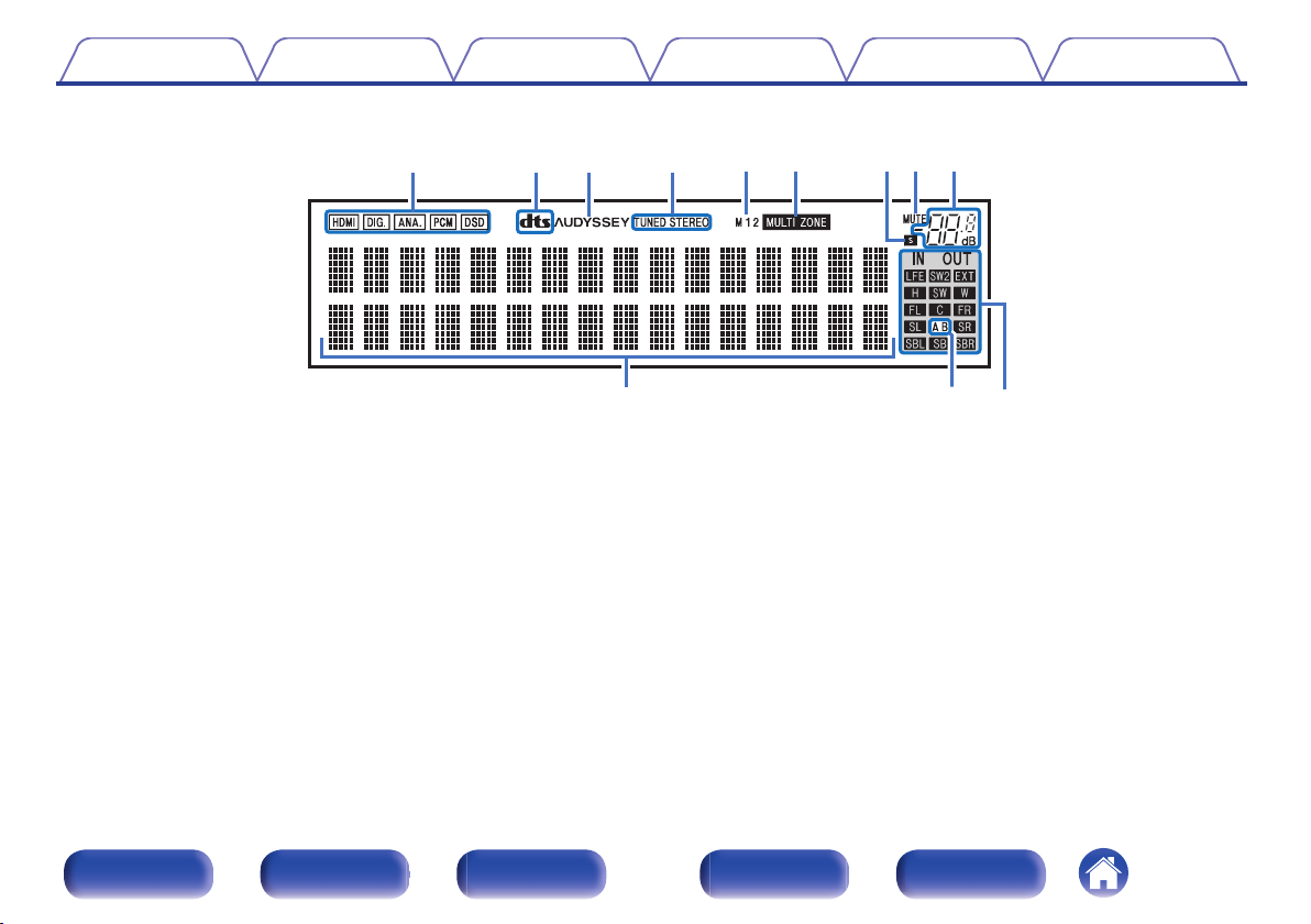
o
Sub display
Input signal indicators
A
These light according to the audio input mode settings of each input
source. (v p. 205)
Decoder indicators
B
These light when DTS signals are input or when the DTS decoder is
running.
C
Audyssey® indicator
This lights when “MultEQ® XT32”, “Dynamic EQ”, “Dynamic Volume” or
“Audyssey LFCTM” has been set up. (v p. 187)
Front panel Display Rear panel Remote Index
Tuner reception mode indicators
D
These light up according to the reception conditions when the input
source is set to “Tuner”.
TUNED: Lights up when the broadcast is properly tuned in.
STEREO: Lights up when receiving FM stereo broadcasts.
HDMI output indicator
E
These light according to the HDMI output setting. When set to
“Auto(Dual)”, the indicators light according to connection status.
MULTI ZONE indicator
F
This lights up when ZONE2 or ZONE3 (another room) power is turned
on. (v p. 168)
27
Page 28
Q0 Q1 Q2
iuo
Contents Connections Playback Settings Tips Appendix
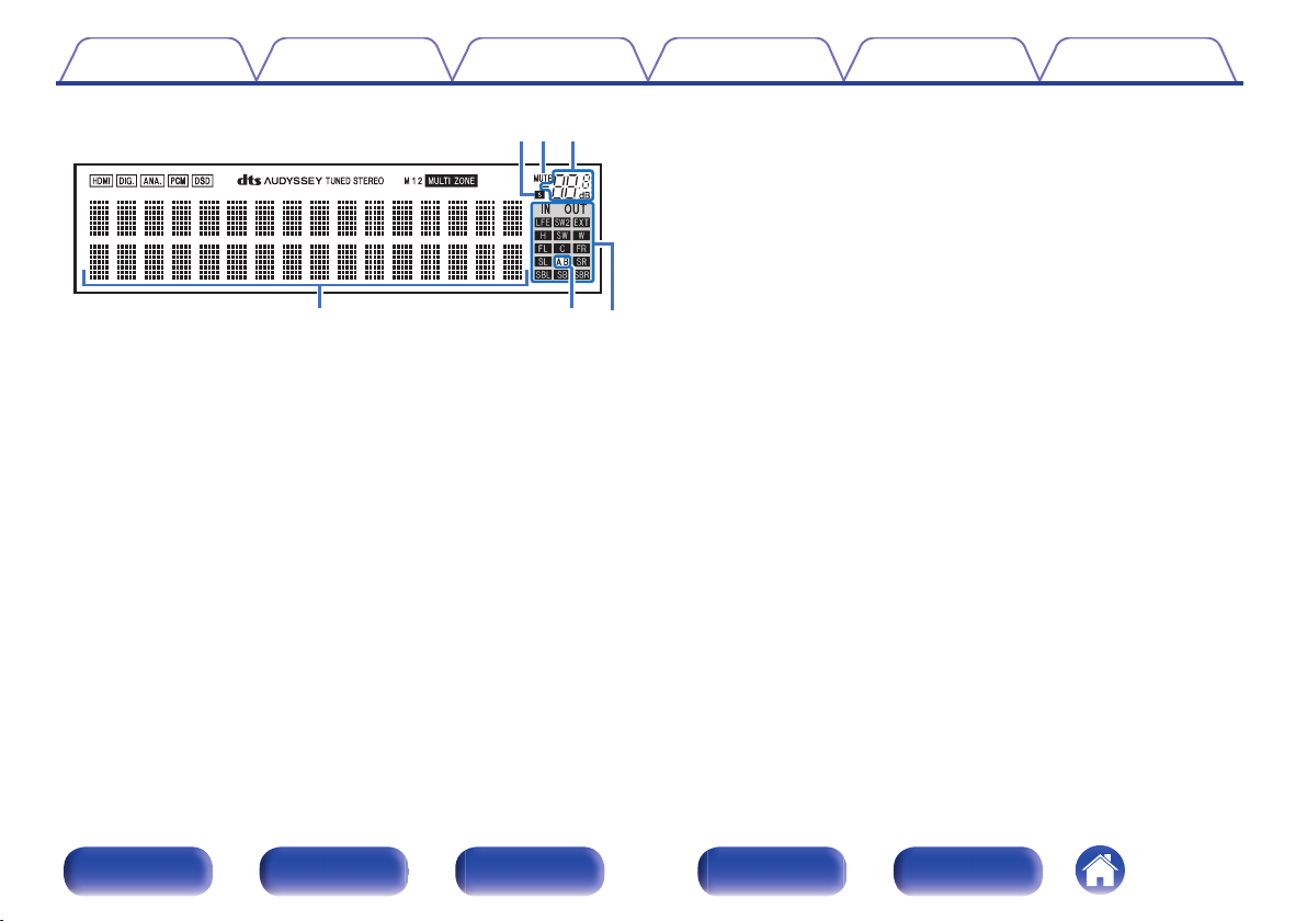
Input/output signal channel indicators
L
The channel for input/output signals is displayed according to the
setting configured for “Channel Indicator”. (v p. 261)
When “Channel Indicator” is set to “Output” (Default)
0
These light when audio signals are being output from the speakers.
When “Channel Indicator” is set to “Input”
0
These light corresponding to the channels that include the input
signals.
When playing HD Audio sources, the A indicator lights when a
signal from an extension channel (a channel other than the front,
Sleep timer indicator
G
This lights when the sleep mode is selected. (v p. 152)
MUTE indicator
H
This blinks while the sound is muted. (v p. 88)
Volume indicator
I
Information display
J
The input source name, sound mode, setting values and other
information are displayed here.
Front speaker indicator
K
This lights according to the setting of the front A and B speakers.
center, surround, surround back, front height, front wide or LFE
channel) is input.
Front panel Display Rear panel Remote Index
28
Page 29
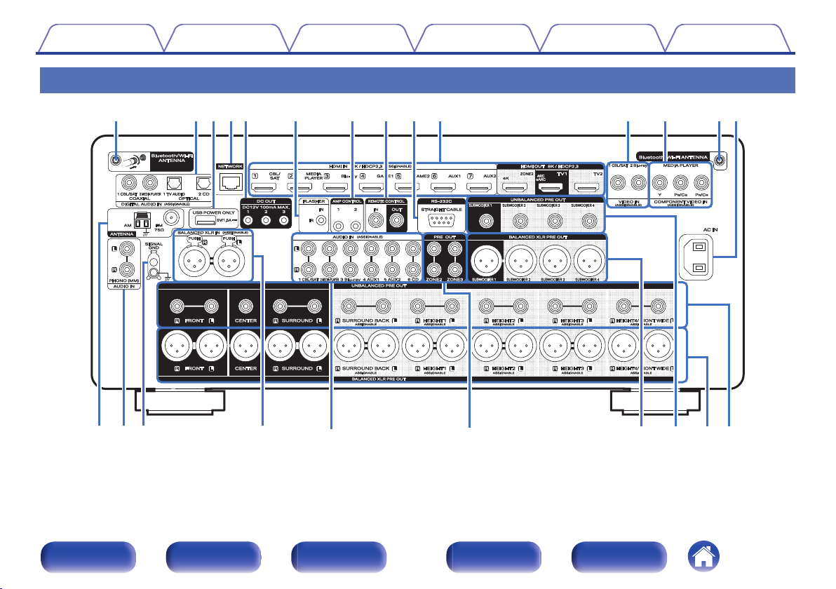
ty uiow
Q0 qqQ3
re
Q1 Q2
Q
5
Q
6
Q
4
W
0Q9
Q
9
Q
7
W
0
Q
5
Q
8
Contents
Rear panel
Connections Playback Settings Tips Appendix
For details, see the next page.
Front panel Display Rear panel Remote Index
29
Page 30
wer t
q
y
qwe
Contents
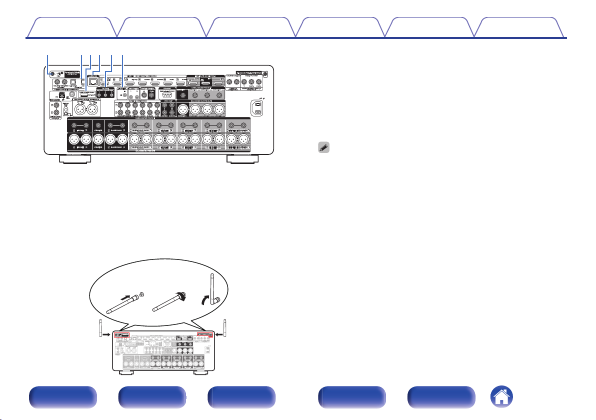
Bluetooth/wireless LAN antenna connectors
A
Connections Playback Settings Tips Appendix
Used to connect the included external antennas for Bluetooth/wireless
connectivity when connecting to a network via wireless LAN, or when
connecting to a handheld device via Bluetooth. (v p. 79)
Place the external antennas for Bluetooth/wireless connectivity
A
evenly over the screw terminal of rear.
Turn clockwise until the antennas is fully connected.
B
Rotate the antenna upwards for best reception.
C
Digital audio connectors (DIGITAL AUDIO)
B
Used to connect devices equipped with digital audio connectors.
“Connection 2 : TV equipped with an HDMI connector and
0
incompatible with the ARC / eARC” (v p. 67)
“Connecting a set-top box (Satellite tuner/cable TV)” (v p. 70)
0
“Connecting a media player” (v p. 71)
0
USB port (POWER SUPPLY)
C
Can be used to power streaming media players, etc.
Use a device’s supplied AC adapter when a power supply of 5 V/1.5 A or more
0
is required.
Connect to the USB port on the front panel to play content from a USB
0
memory device.
NETWORK connector
D
Used to connect to a LAN cable when connecting to a wired LAN
network. (v p. 78)
DC OUT jacks
E
Used to connect devices equipped with the trigger function.
(v p. 84)
FLASHER IN jack
F
Used to connect commercially available (sold separately) IR repeaters.
(v p. 83)
Front panel Display Rear panel Remote Index
30
Page 31
ui o Q0 Q1
Contents
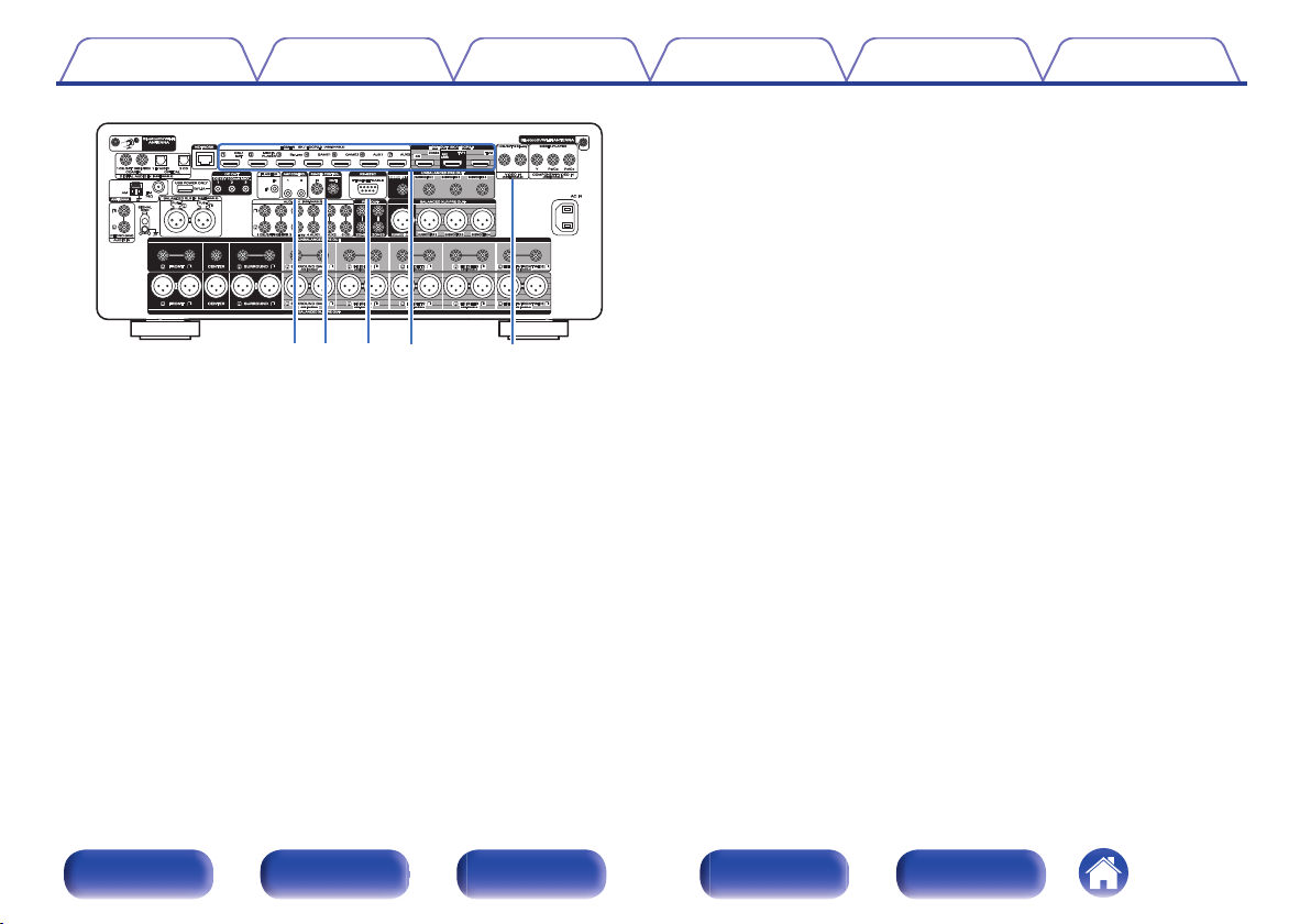
AMP CONTROL jacks
G
Connections Playback Settings Tips Appendix
Used to connect a Marantz power amp that is equipped with AMP
CONTROL terminals. You can turn this unit on/standby or change the
brightness of the display in conjunction with the power amp.
(v p. 80)
REMOTE CONTROL jacks
H
Used to connect a Marantz product that is equipped with REMOTE
CONTROL terminals. Use this when you want to control this unit with a
remote control. (v p. 81)
RS-232C connector
I
Used to connect home automation controller devices fitted with
RS-232C connectors. Consult the owner’s manual of the home
automation controller for more information about serial control of this
unit.
Perform the operation below beforehand.
Turn on the power of this unit.
A
Turn off the power of this unit from the external controller.
B
Check that the unit is in the standby mode.
C
HDMI connectors
J
Used to connect devices equipped with HDMI connectors.
“Connection 1 : TV equipped with an HDMI connector and
0
compatible with the ARC / eARC” (v p. 66)
“Connection 2 : TV equipped with an HDMI connector and
0
incompatible with the ARC / eARC” (v p. 67)
“Connecting a set-top box (Satellite tuner/cable TV)” (v p. 70)
0
“Connecting a media player” (v p. 71)
0
“Connecting a Blu-ray Disc player or DVD player” (v p. 72)
0
“Connecting a game console or player device compatible with
0
8K” (v p. 73)
Video connectors (VIDEO)
K
Used to connect devices equipped with video connectors.
“Connecting a set-top box (Satellite tuner/cable TV)” (v p. 70)
0
“Connecting a Blu-ray Disc player or DVD player” (v p. 72)
0
Front panel Display Rear panel Remote Index
31
Page 32
Q4 Q7Q6
Q5 Q8 Q9 Q9W0W0
Q2Q5 Q3
Contents Connections Playback Settings Tips Appendix
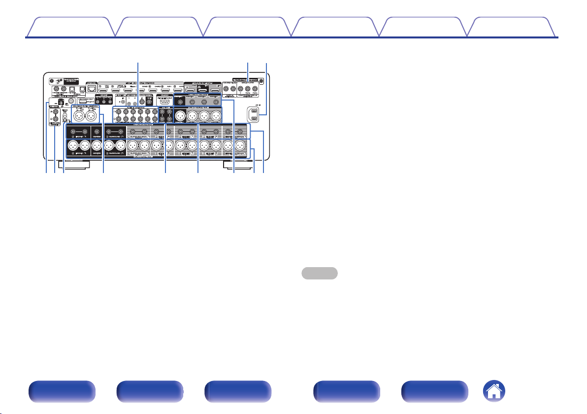
Analog audio connectors (AUDIO)
O
Used to connect devices equipped with analog audio connectors.
“Connecting a set-top box (Satellite tuner/cable TV)” (v p. 70)
0
“Connecting a media player” (v p. 71)
0
“Connecting a Blu-ray Disc player or DVD player” (v p. 72)
0
“Connecting a turntable” (v p. 74)
0
SIGNAL GND terminal
P
Used to connect a ground wire for the turntable. (v p. 74)
BALANCED XLR INPUT connectors
Q
Used to connect a preamplifier with BALANCED XLR output
connectors.
PRE OUT connectors
R
Component video connectors (COMPONENT VIDEO)
L
Used to connect devices equipped with component video connectors.
“Connecting a media player” (v p. 71)
0
AC inlet (AC IN)
M
Used to connect the power cord. (v p. 85)
FM/AM antenna terminals (ANTENNA)
N
Used to connect FM antennas and AM loop antennas. (v p. 76)
Used to connect an external power amplifier. (v p. 164)
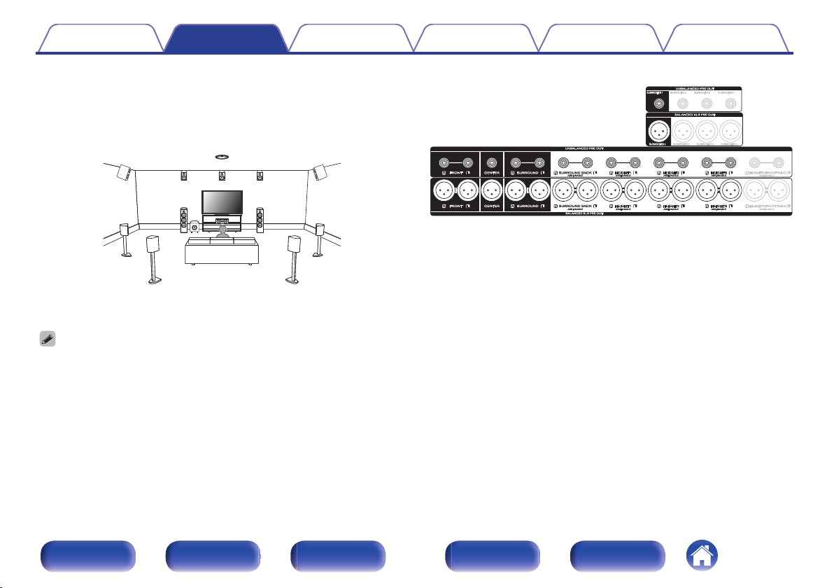
BALANCED XLR PRE OUT connectors
S
Used to connect a power amp with BALANCED XLR input connectors.
(v p. 43)
UNBALANCED RCA PRE OUT connectors
T
Used to connect a power amp with UNBALANCED RCA input
connectors. (v p. 45)
NOTE
Do not touch the inner pins of the connectors on the rear panel. Electrostatic
0
discharge may cause permanent damage to the unit.
Front panel Display Rear panel Remote Index
32
Page 33
q
w
e
t
r
Contents
Connections Playback Settings Tips Appendix
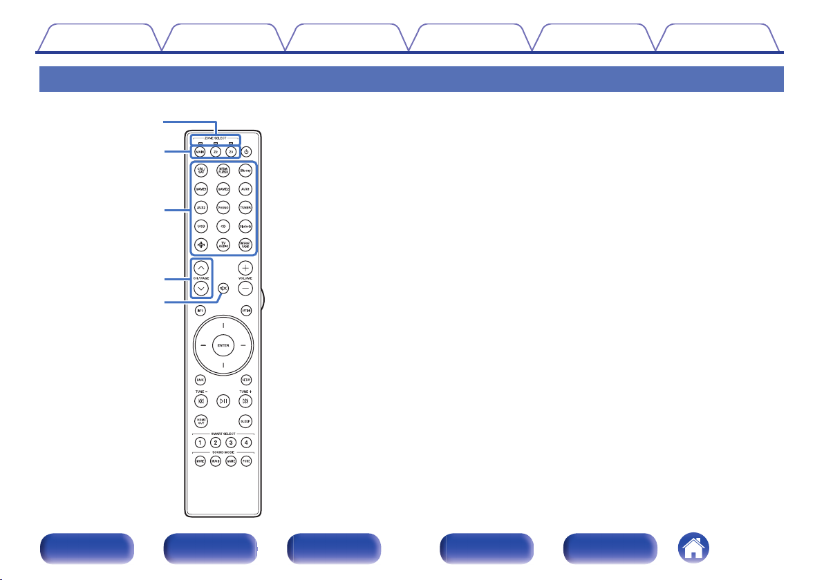
Remote control unit
Zone mode indicators
A
The indicator of the zone that you are operating lights up.
ZONE SELECT buttons (MAIN, Z2, Z3)
B
These switch the zone (MAIN ZONE, ZONE2, ZONE3) that is operated
through the remote control unit.
“Playing different sources in MAIN ZONE, ZONE2 and
0
ZONE3” (v p. 168)
“Menu operations” (v p. 176)
0
“Specifying the zone used with the remote control unit” (v p. 269)
0
Input source select buttons
C
These selects the input source.
“Selecting the input source” (v p. 87)
0
“Playing different sources in MAIN ZONE, ZONE2 and
0
ZONE3” (v p. 168)
Channel/page search buttons (CH/PAGE ml)
D
These select radio stations registered to presets or switch pages.
(v p. 105)
MUTE button (:)
E
This mutes the output audio.
“Turning off the sound temporarily (Muting)” (v p. 88)
0
“Turning off the sound temporarily (Muting)” (v p. 170)
0
Front panel Display Rear panel Remote Index
33
Page 34
Q3
o
Q1
Q2
y
Q0
i
u
Contents
Connections Playback Settings Tips Appendix
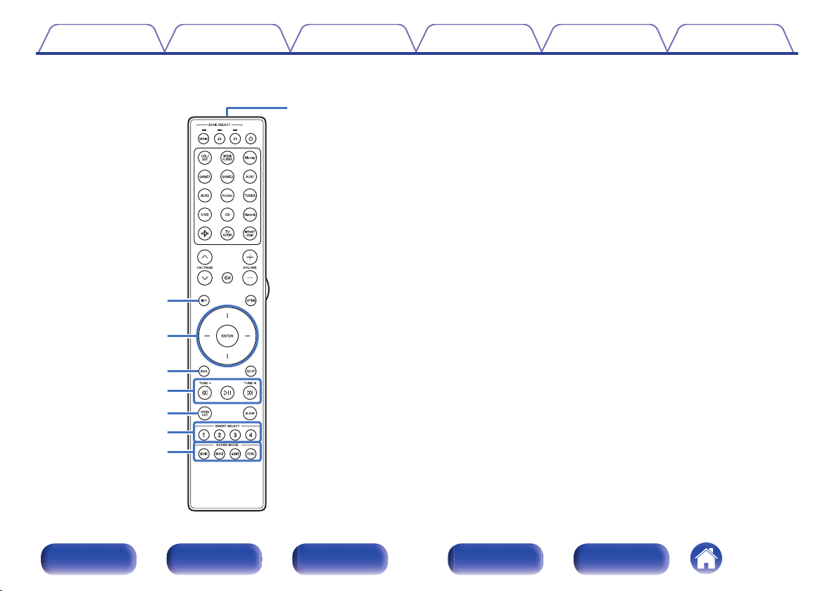
Information button (INFO)
F
This displays the status information on the TV screen. (v p. 265)
Cursor buttons
G
These select items.
BACK button
H
This returns to the previous screen.
System buttons
I
These perform playback related operations.
Tuning up / Tuning down buttons (TUNE +, –)
These select either FM broadcast or AM broadcast. (v p. 102)
HDMI OUT button
J
This sets the HDMI monitor output. (v p. 198)
SMART SELECT buttons (1 – 4)
K
These call up settings registered to each button, such as input source,
volume level and sound mode settings. (v p. 154)
SOUND MODE buttons
L
These select the sound mode. (v p. 137)
Remote control signal transmitter
M
This transmits signals from the remote control unit. (v p. 10)
Front panel Display Rear panel Remote Index
34
Page 35
Q4
Q5
Q6
Q8
Q7
Q9
W0
Contents
Connections Playback Settings Tips Appendix
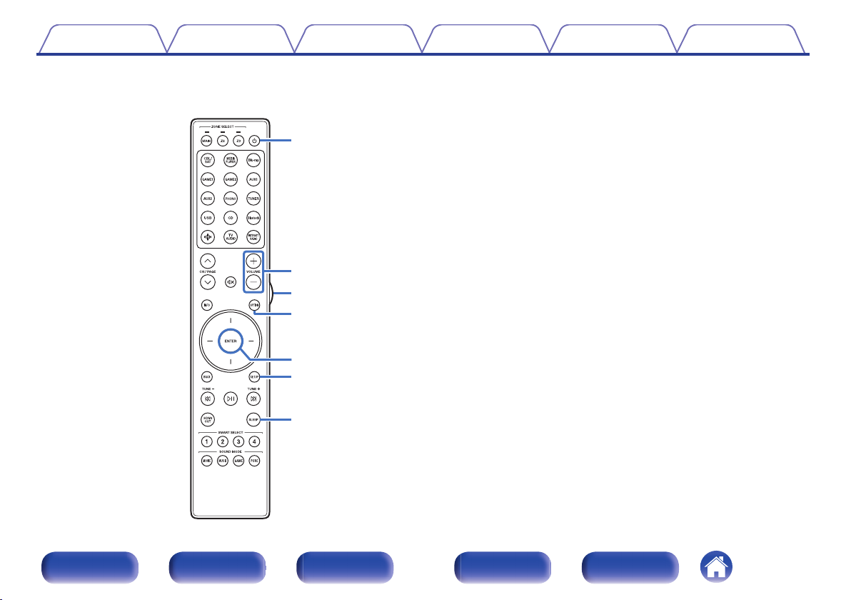
POWER button (X)
N
This turns the power on/off.
“Turning the power on” (v p. 87)
0
“Playback in ZONE2/ZONE3 (Another room)” (v p. 163)
0
VOLUME buttons (no)
O
These adjusts the volume level.
“Adjusting the volume” (v p. 88)
0
“Adjusting the Volume in ZONE2/ZONE3” (v p. 170)
0
Light button
P
This turns on the backlight for approx. 5 seconds. (v p. 268)
OPTION button
Q
This displays the option menu on the TV screen.
ENTER button
R
This determines the selection.
SETUP button
S
This displays the menu on the TV screen. (v p. 176)
SLEEP button
T
This sets the sleep timer. (v p. 152)
Front panel Display Rear panel Remote Index
35
Page 36
R
L
R
L
Contents Connections Playback Settings Tips Appendix
o
Contents
Speaker installation 37
Connecting a power amp 43
Connecting a TV 65
Connecting a playback device 68
Connecting a USB memory device to the USB port 75
Connecting FM/AM antennas 76
Connecting to a home network (LAN) 78
Connecting an external control device 80
Connecting the power cord 85
NOTE
Do not plug in the power cord until all connections have been completed.
0
However, when the “Setup Assistant” is running, follow the instructions in the
“Setup Assistant” (page 9 in the separate “Quick Start Guide”) screen for making
connections. (During “Setup Assistant” operation, the input/output connectors do
not conduct current.)
Do not bundle power cords together with connection cables. Doing so can result in
0
noise.
o
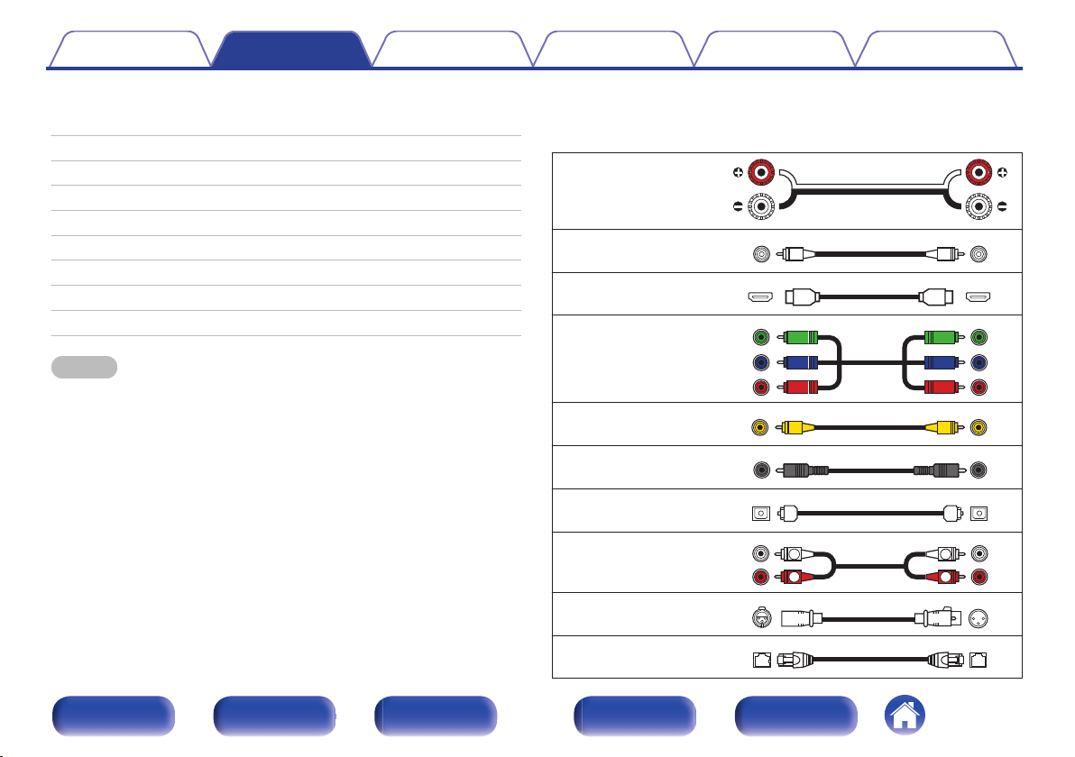
Cables used for connections
Provide necessary cables according to the devices you want to
connect.
Speaker cable
Subwoofer cable
HDMI cable
Component video cable
Video cable
Coaxial digital cable
Optical cable
Audio cable
XLR cable
LAN cable
Front panel Display Rear panel Remote Index
36
Page 37
C
FL FR
SBL
SBR
SB
SW1
FWL
FWR
SL SR
SW3 SW4
SW2
Contents Connections Playback Settings Tips Appendix
Speaker installation
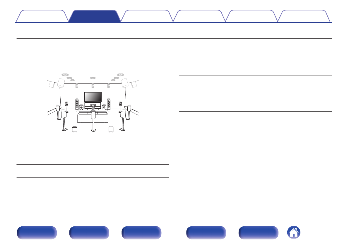
Determine the speaker system depending on the number of speakers you
are using and install each speaker and subwoofer in the room.
Speaker installation is explained using this example of a typical
installation.
SL/SR
(Surround speaker left/
right):
SBL/SBR
(Surround back
speaker left/right):
FWL/FWR
(Front wide speaker
left/right):
FL/FR
(Front speaker left/
right):
C
(Center speaker):
Front panel Display Rear panel Remote Index
Place the FRONT left and right speakers an
equal distance from the main listening position.
The distance between each speaker and your TV
should also be the same.
Place the CENTER speaker in between the front
speakers and above or below your TV.
SW 1/2/3/4
(Subwoofer):
37
Place the SURROUND left and right speakers an
equal distance to the left and right sides of the
main listening position. If you don’t have
surround back speakers, move the surround
speakers slightly behind your listening position.
Place the SURROUND BACK left and right
speakers an equal distance from the main
listening position and directly behind the main
listening position. When using a single surround
back speaker (SB), place it directly behind the
listening position.
Place the FRONT WIDE left and right speakers
outside of the front left and right speakers so that
there is an equal distance between all front
speakers.
Place your subwoofer near your front speakers. If
you are using multiple subwoofers, place pairs of
subwoofers spaced equally across the front or
rear walls of the room or place single subs
midway between the front pairs or rear pairs.
You can also set a specific layout when using
multiple subwoofers on the “Subwoofer Mode”
setting (v p. 228):
2 subwoofers: 2 front, or 1 front and 1 rear
3 subwoofers: 2 front and 1rear
4 subwoofers: 2 front and 2 rear
Page 38
FHL FHR
TRR
TRL
TFR
TFL
RHL RHR
TMR
TML
Contents Connections Playback Settings Tips Appendix
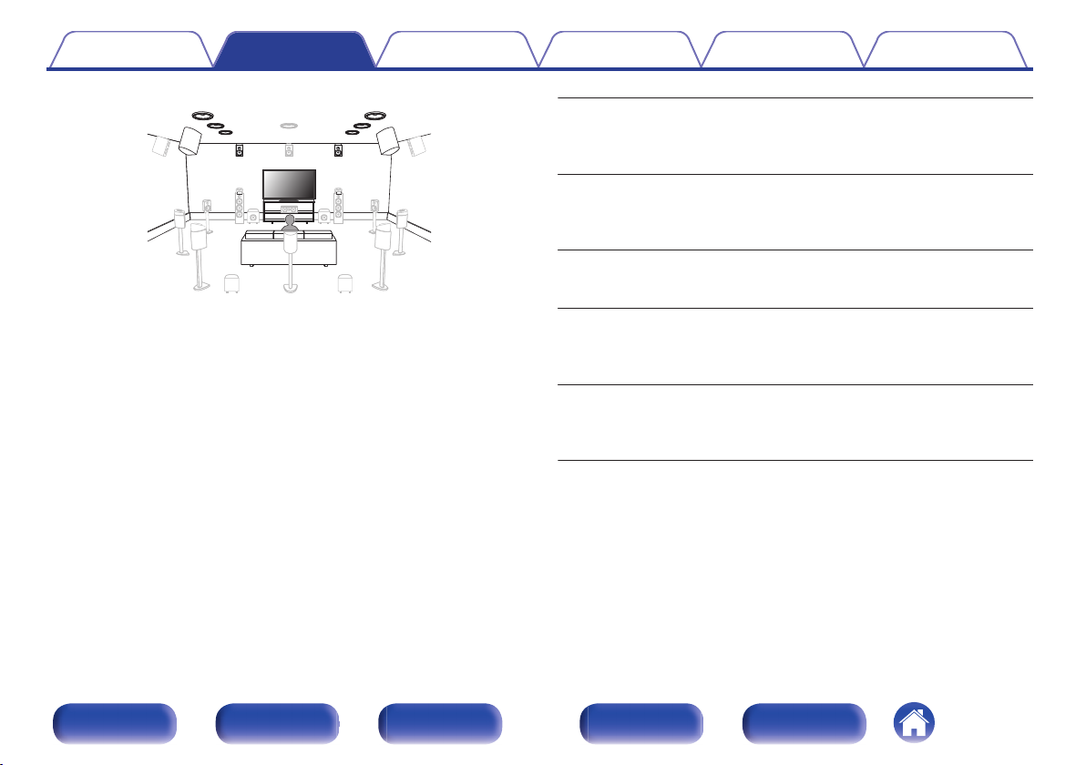
FHL/FHR
(Front height speaker
left/right):
TFL/TFR
(Top front speaker
left/right):
TML/TMR
(Top middle speaker
left/right):
TRL/TRR
(Top rear speaker
left/right):
RHL/RHR
(Rear height speaker
left/right):
Place the FRONT HEIGHT left and right speakers
directly above the front speakers. Mount them as
close to the ceiling as possible and aim them
towards the main listening position.
Mount the TOP FRONT left and right speakers on
the ceiling slightly in front of your main listening
position and aligned with the left and right front
speakers.
Mount the TOP MIDDLE left and right speakers
directly above the main listening position and
aligned with the left and right front speakers.
Mount the TOP REAR left and right speakers on
the ceiling slightly behind your main listening
position and aligned with the left and right front
speakers.
Place the REAR HEIGHT left and right speakers
directly behind the main listening position. Mount
them as close to the ceiling as possible and
aligned with the left and right front speakers.
Front panel Display Rear panel Remote Index
38
Page 39
SHL
SHR
TS
CH
Contents Connections Playback Settings Tips Appendix
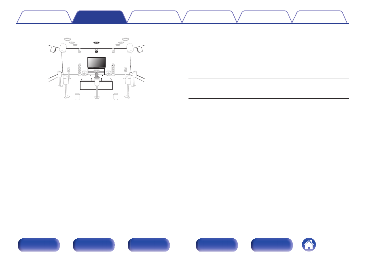
SHL/SHR
(Surround height
speaker left/right):
CH
(Center height
speaker):
TS
(Top surround
speaker):
Place the SURROUND HEIGHT left and right
speakers directly above the surround speakers.
Place the CENTER HEIGHT speaker directly
above the center speaker. Mount them as close to
the ceiling as possible and aim them towards the
main listening position.
Place the TOP SURROUND speaker directly
above the main listening position and aligned with
the center channel speaker.
Front panel Display Rear panel Remote Index
39
Page 40
FDL FDR
BDL BDR
SDL SDR
Contents Connections Playback Settings Tips Appendix
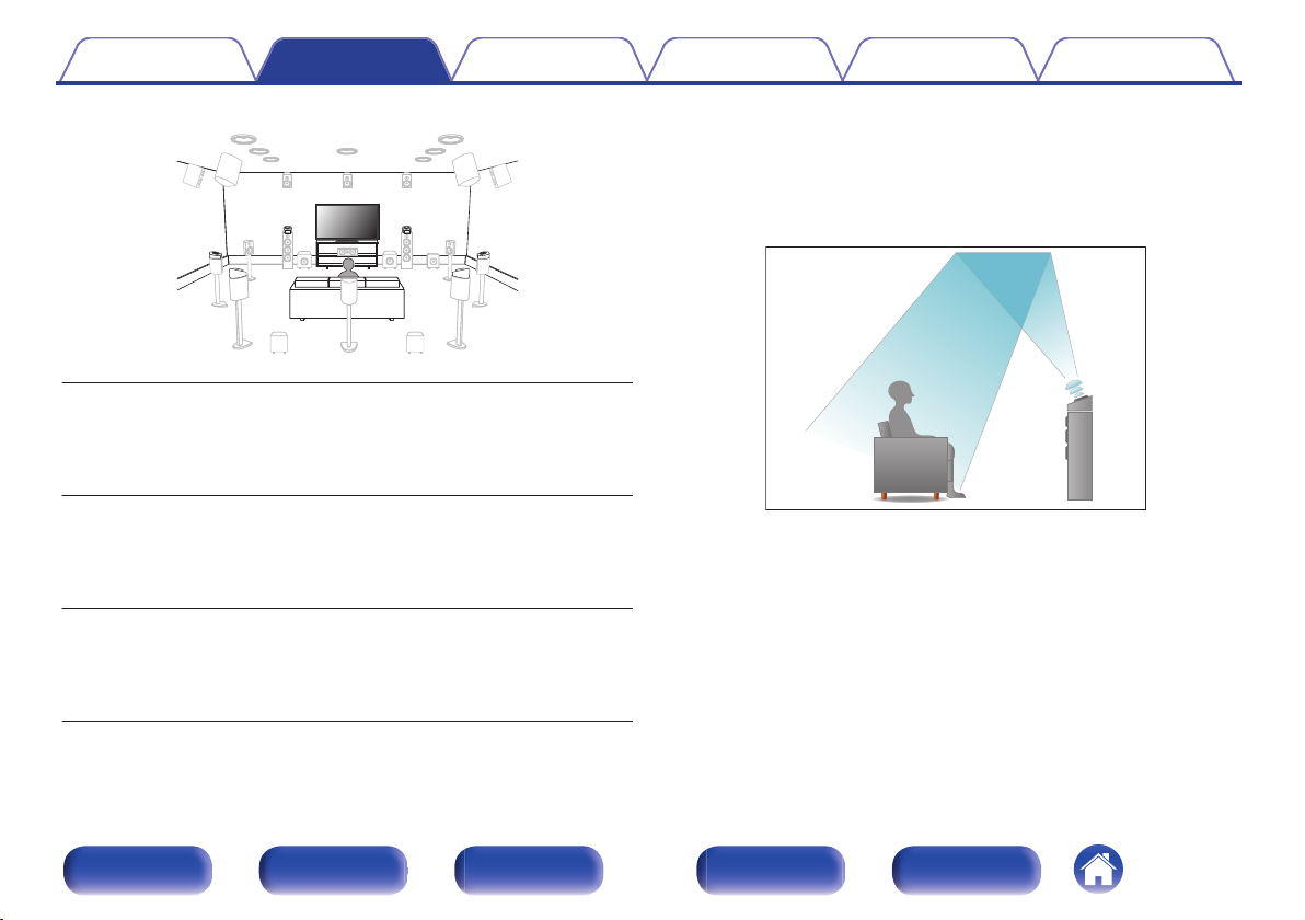
About Dolby Atmos Enabled speakers
Dolby Atmos Enabled speakers reflect the sound off the ceiling to allow
the sound to come from over your head by using a special upwardpointing speaker that is placed on the floor.
You can enjoy the Dolby Atmos 3D sound even in an environment where
speakers cannot be installed on the ceiling.
FDL/FDR
(Front Dolby speaker
left/right):
on the front speaker. For a Dolby Atmos Enabled
integrated with a front speaker, place the Dolby
Atmos Enabled speaker instead of the front
speaker.
Place the SURROUND Dolby Atmos Enabled
Place the FRONT Dolby Atmos Enabled speaker
SDL/SDR
(Surround Dolby
speaker left/right):
speaker on the surround speaker. For a Dolby
Atmos Enabled speaker integrated with a surround
speaker, place the Dolby Atmos Enabled speaker
instead of the surround speaker.
Place the BACK Dolby Atmos Enabled speaker on
BDL/BDR
(Back Dolby speaker
left/right):
the surround back speaker. For a Dolby Atmos
Enabled speaker integrated with a surround back
speaker, place the Dolby Atmos Enabled speaker
instead of the surround back speaker.
Front panel Display Rear panel Remote Index
40
Page 41
FL
SW
C
SL
FR
SR
FWL
FWR
SBL
SBR
z3
z2
z1
z4
Contents
This unit is compatible with Dolby Atmos and DTS:X which offers an even wider
0
and deeper surround sensation.
The “Speaker Virtualizer” must be set to “On” for Dolby Atmos playback with 5.1-
0
channel speaker configurations or less. (v p. 180)
IMAX DTS:X / DTS:X can be selected regardless of the speaker configuration.
0
AURO-3D recommends adding FRONT HEIGHT and SURROUND HEIGHT
0
speakers to a 5.1 speaker configuration. Optionally, you may substitute REAR
HEIGHT, ceiling speakers, Dolby Atmos Enabled speakers instead of FRONT
HEIGHT and SURROUND HEIGHT speakers for Dolby Atmos, DTS:X and
AURO-3D playback.
Connections Playback Settings Tips Appendix
o
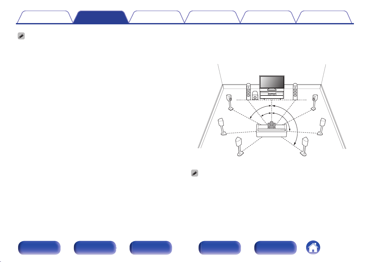
Recommended placement of the speakers
Floor speakers Layout
Use the following illustration as a guide for the installation location of
0
each floor speaker. You do not have to match them exactly.
z
1 22° - 30° z2 50° - 70° z3 90° - 110° z4 135° - 150°
If you are not using the surround back speakers, the recommended angle of the
0
surround sound speakers (z3) is 120°.
When using a single surround back speaker, place it directly behind the listening
0
position.
Front panel Display Rear panel Remote Index
41
Page 42
z
1
z2
z3
z4
z5
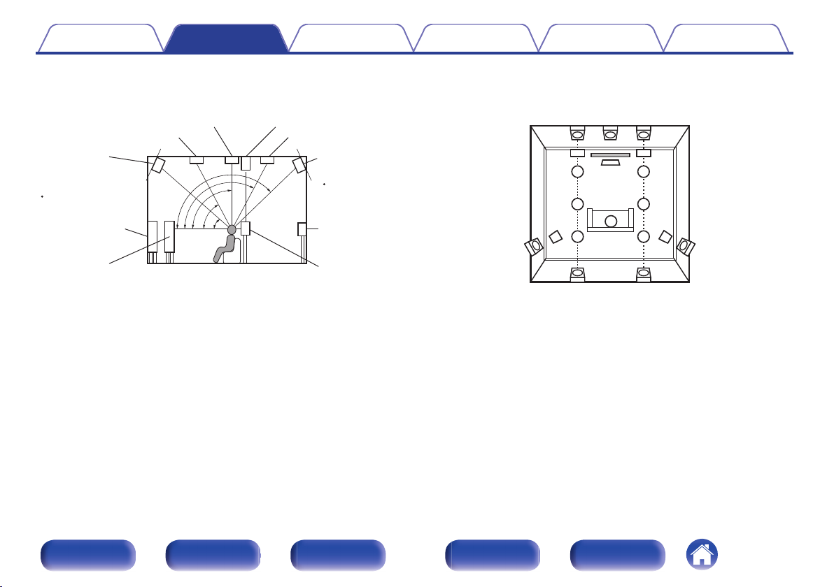
Point slightly
downwards
z1 30° - 45°
z4 125° - 150°
z2 30° - 55°
z3 65° - 100°
z5 135° - 150°
GViewed from the sideH
Top front speaker Top rear speaker
Front speaker
Surround
speaker
Surround
back
speaker
Point slightly
downwards
Rear height
speaker
Top middle / Top surround speaker Surround height speaker
Front height /
Center height
speaker
Front wide
speaker
TS
SL
TRL
RHL RHR
FHL
TML
TFL
FL
SR
TRR
FHRCH
TMR
TFR
FR
C
SHRSHL
GViewed from the topH
Contents Connections Playback Settings Tips Appendix
Height speakers Layout
Use the following illustration as a guide for the installation location of each height speaker. You do not have to match them exactly.
0
Front panel Display Rear panel Remote Index
42
Page 43
1
2
3
Contents Connections Playback Settings Tips Appendix
Connecting a power amp
Before connecting a power amp
Connect a power amp (sold separately) to the PRE OUT connector of
0
this unit.
This unit has UNBALANCED RCA PRE OUT connector and
0
BALANCED XLR PRE OUT connector. Connect to the correct
connector for your power amp. If your power amp has both connectors,
connect to either of them.
Connect the speakers to the power amp.
0
For details on speaker connections, see the Owner's Manual for the
0
power amp.
This section shows how to make a 15.4-channel connection.
0
For how to make other speaker connections, see page 48.
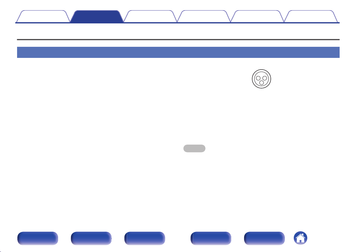
GAV 20 BALANCED XLR PRE OUT connector PIN arrangementH
GND (Ground)
A
HOT (+)
B
COLD (–)
C
The PIN arrangement in this unit uses the European method.
In the USA method, B is COLD, and C is HOT.
When connecting a device that utilizes the USA type of PIN arrangement,
replace the B and C plugs on one side of the balanced cable.
NOTE
Do not short the HOT and GND or COLD and GND for use.
0
Disconnect this unit’s power plug from the power outlet before connecting the
0
speakers.
Also, turn off the power amp and subwoofer.
Front panel Display Rear panel Remote Index
43
Page 44
z
1
z
3
z3z
3
z
3
z3z
3
SW4 SW3 SW2 SW1
SR SLFR FL C TMR TML
z
2
z
2
FWR FWL
z
2,
z
3
z
2,
z
3
CH TS
RHR RHL
FHR FHL
SBLSBR
Marantz
AMP 20
Marantz
AMP 20
Second unit
Contents
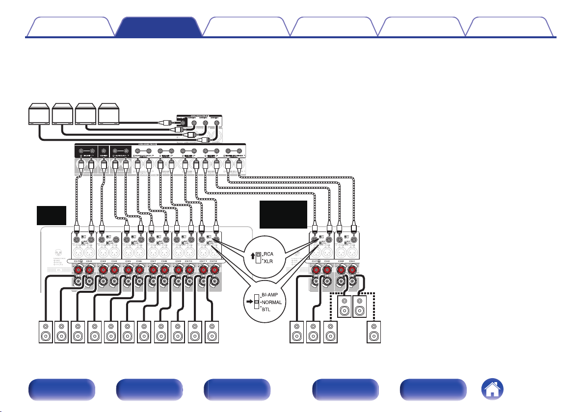
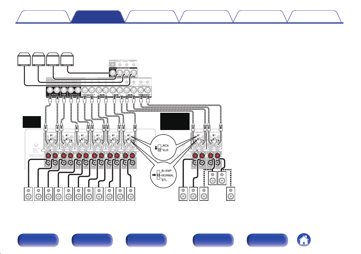
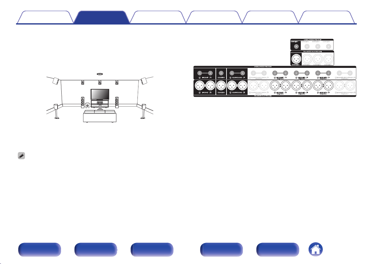
Example of connections to Marantz AMP 20 power amp
o
n
Connecting the UNBALANCED RCA PRE OUT connector
When using UNBALANCED RCA connectors for connection, set the input change switch to “RCA” on Marantz AMP 20.
Connections Playback Settings Tips Appendix
When using a single surround back speaker,
z1
connect it to the SURROUND BACK L terminal.
The 4th set of height speakers can be connected
z2
to the HEIGHT4/FRONT WIDE RCA connectors
instead of the Front Wide channel.
The output terminals for Height/Ceiling/Dolby
z3
Atmos Enabled speakers vary according to the
speaker combination that you use. For the PRE
OUT connector that connects each Height/
Ceiling/Dolby Atmos Enabled speaker, refer to
“Speaker Layout” in the menu (v p. 219).
44
Front panel Display Rear panel Remote Index
Page 45
z
1
SR SLFR FL C RHR RHLFHR FHL
SBLSBR
SW4 SW3 SW2 SW1
z
3
z3z
3
z
3
z3z
3
TMR TML
z
2
z
2
FWR FWL
z
2,
z
3
z
2,
z
3
CH TS
Marantz
AMP 20
Marantz
AMP 20
Second unit
Contents
n
Connecting the BALANCED XLR PRE OUT connector
When using BALANCED XLR connectors for connection, set the input change switch to “XLR” on Marantz AMP 20.
Connections Playback Settings Tips Appendix
When using a single surround back speaker,
z1
connect it to the SURROUND BACK L terminal.
The 4th set of height speakers can be connected
z2
to the HEIGHT4/FRONT WIDE XLR connectors
instead of the Front Wide channel.
The output terminals for Height/Ceiling/Dolby
z3
Atmos Enabled speakers vary according to the
speaker combination that you use. For the PRE
OUT connector that connects each Height/
Ceiling/Dolby Atmos Enabled speaker, refer to
“Speaker Layout” in the menu (v p. 219).
45
Front panel Display Rear panel Remote Index
Page 46
Contents Connections Playback Settings Tips Appendix
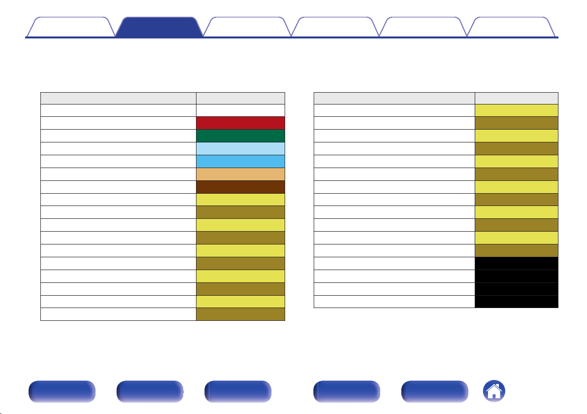
About the cable labels (supplied) for channel identification
o
Attach the cable label corresponding to each speaker to each speaker cable.
This makes it easier to connect the speakers to the power amp.
Channel Color
FRONT L White
FRONT R Red
CENTER Green
SURROUND L Light Blue
SURROUND R Blue
SURROUND BACK L Beige
SURROUND BACK R Brown
FRONT WIDE L Light Yellow
FRONT WIDE R Yellow
FRONT HEIGHT L Light Yellow
FRONT HEIGHT R Yellow
TOP FRONT L Light Yellow
TOP FRONT R Yellow
TOP MIDDLE L Light Yellow
TOP MIDDLE R Yellow
TOP REAR L Light Yellow
TOP REAR R Yellow
Channel Color
SURROUND HEIGHT L Light Yellow
SURROUND HEIGHT R Yellow
REAR HEIGHT L Light Yellow
REAR HEIGHT R Yellow
TOP SURROUND Light Yellow
CENTER HEIGHT Yellow
FRONT DOLBY L Light Yellow
FRONT DOLBY R Yellow
SURROUND DOLBY L Light Yellow
SURROUND DOLBY R Yellow
BACK DOLBY L Light Yellow
BACK DOLBY R Yellow
SUBWOOFER 1 Black
SUBWOOFER 2 Black
SUBWOOFER 3 Black
SUBWOOFER 4 Black
Front panel Display Rear panel Remote Index
46
Page 47
Contents
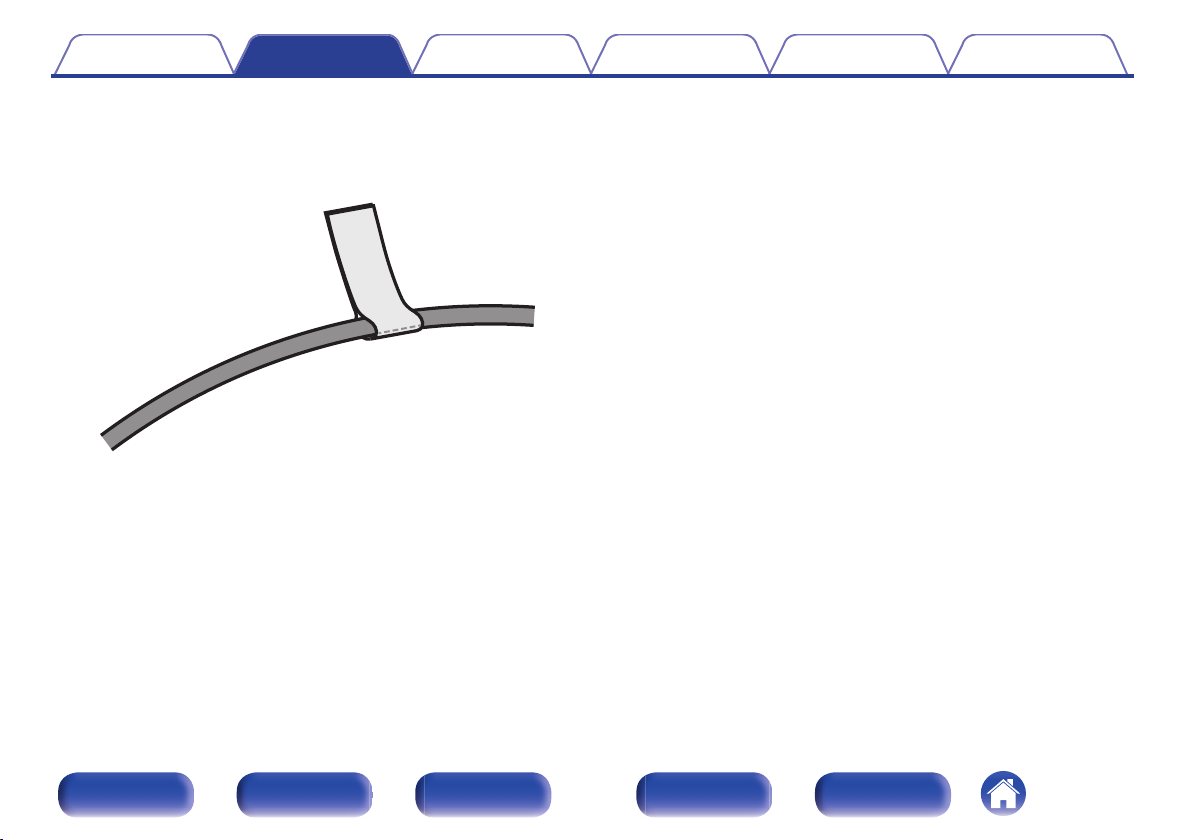
The supplied cable labels include labels for the speaker and HDMI cables.
Attach a cable label to each cable that matches the speakers and HDMI
devices being connected, as shown below. This makes it easy to identify
and properly connect the cables between your components.
G How to attach the cable labels H
Connections Playback Settings Tips Appendix
Front panel Display Rear panel Remote Index
47
Page 48
Contents
Connections Playback Settings Tips Appendix
Speaker configuration and “Amp Assign” settings
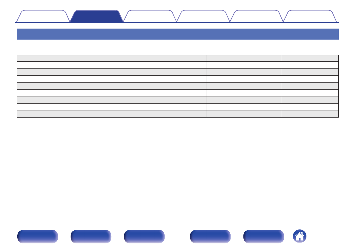
This system configuration plays back 13-channels. You can create speaker systems such as a bi-amp connection by changing the “Amp Assign” settings.
Perform “Speaker Layout” settings to suit the number of rooms and speaker configuration to be installed. (v p. 219)
Playback speaker in MAIN ZONE “Amp Assign” settings Connection page
5.1-channel playback 13.1ch (Default) 50
7.1-channel playback 13.1ch (Default) 51
9.1-channel playback 13.1ch (Default) 53
11.1-channel playback 13.1ch (Default) 56
13.1-channel playback 13.1ch (Default) 59
13.1-channel for Dolby Atmos and 13.1ch for AURO-3D 13.1ch (Default) 62
11.1-channel playback (bi-amp connection of front speakers) 11.1ch (Bi-Amp) 63
11.1-channel playback + second pair of front speakers 11.1ch + Front B 64
The sound mode that can be selected varies according to the speaker configuration.
The following pages provide basic connection examples.
Front panel Display Rear panel Remote Index
48
Page 49
Front
Center
Surround Surround Back Front Height Rear Height
Subwoofer 1 Subwoofer 2 Subwoofer 3 Subwoofer 4
Top Middle
Center
Height
Top
Surround
Back
Speakers/Speaker Layout
Contents
Connections Playback Settings Tips Appendix
Refer to the example connection for “Example layout for AURO-3D 11.1
channel system” (v p. 58) when playing AURO-3D with a 11.1-channel
system using the basic 5.1-channel system and the front height, surround
height, Top Surround and Center Height speakers.
Also refer to the connection example for “Example layout for AURO-3D
13.1 channel system” (v p. 61) when playing AURO-3D with a 13.1channel system by adding the Surround Back, Center Height and Top
Surround speakers.
In addition to the connections described in p. 50 - 64, this unit allows for various
0
speaker connections with the “Speaker Layout” setting.
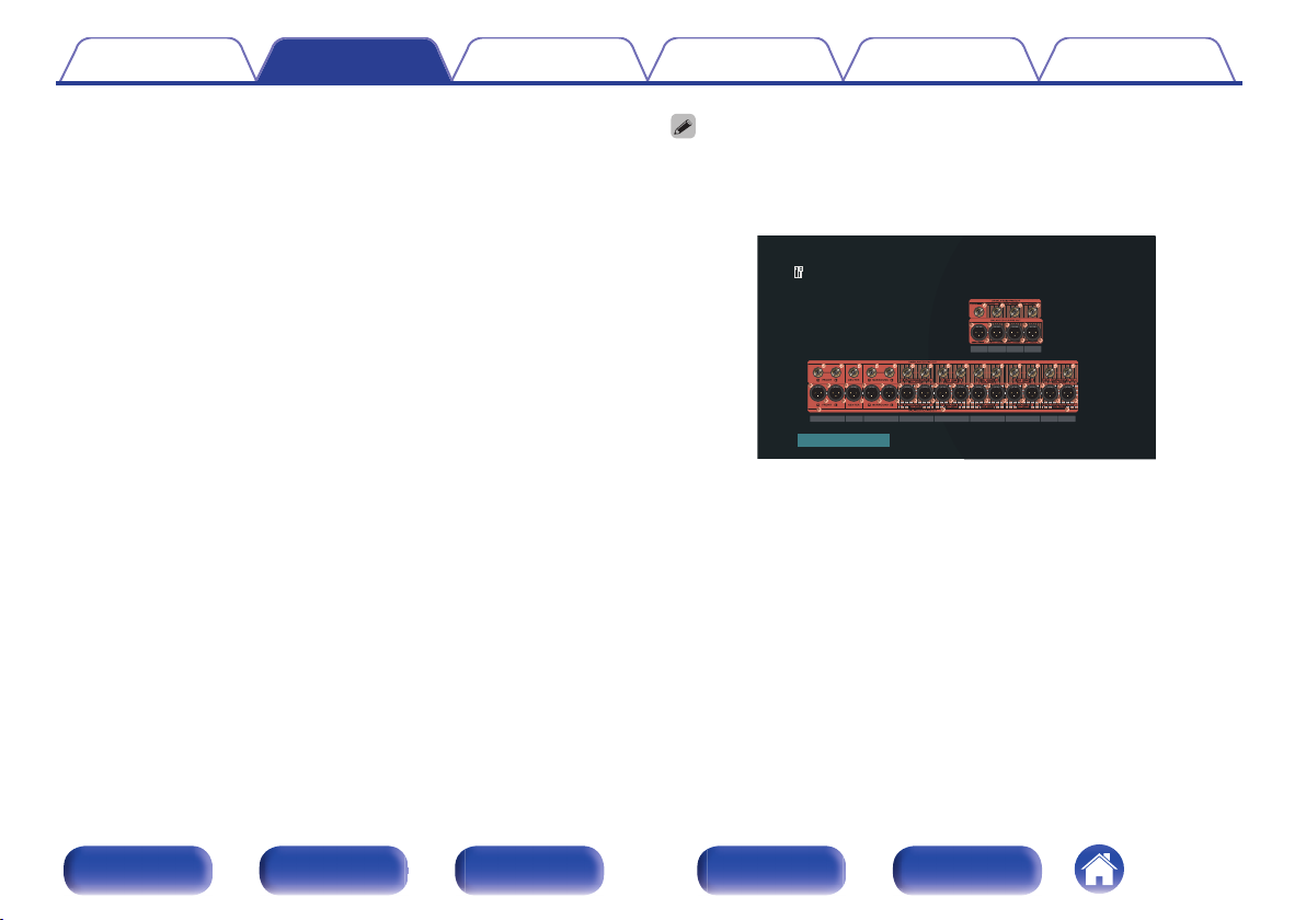
Also refer to the menu screen in “View Terminal Config.” on the “Speaker Layout”
setting screen, which shows how to make connections in your environment.
Front panel Display Rear panel Remote Index
49
Page 50
FL
SW C
SL
FR
SR
Contents Connections Playback Settings Tips Appendix
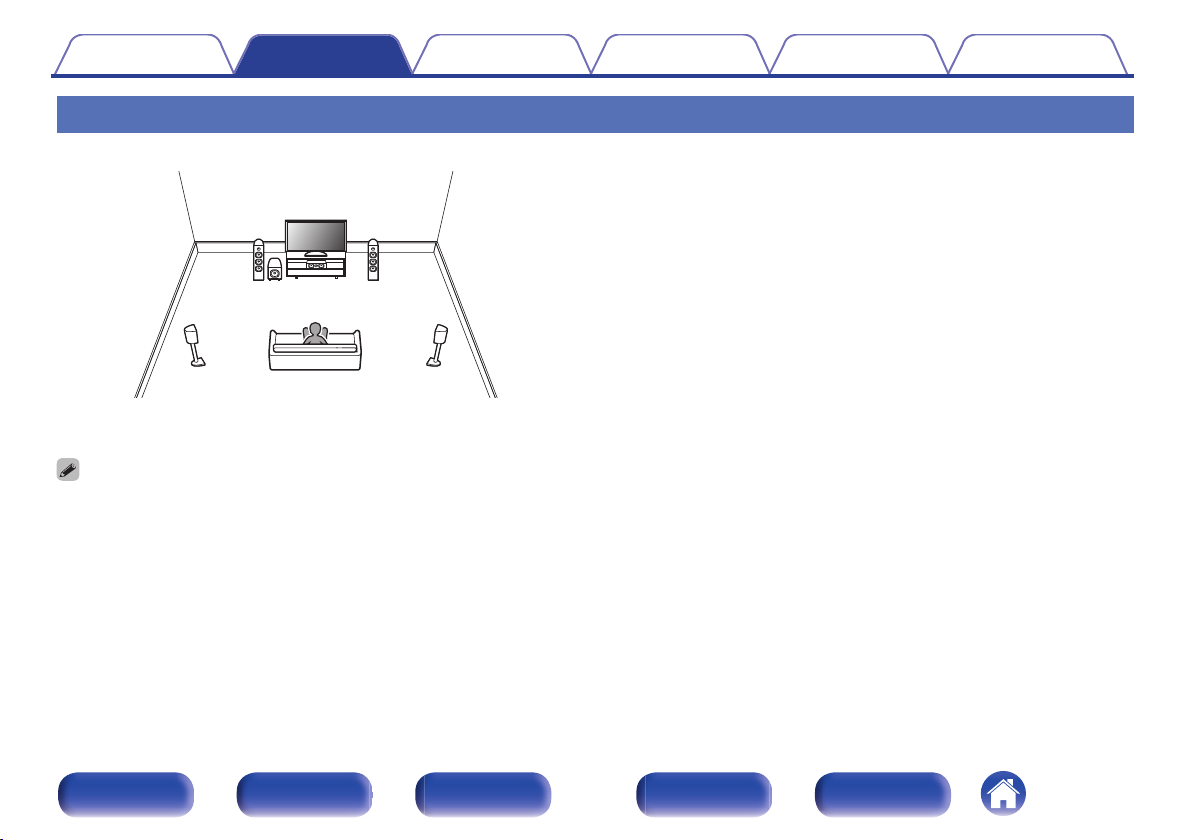
Connecting 5.1-channel speakers
This serves as a basic 5.1-channel surround system.
For each speaker connection, refer to “Connecting a power
amp” (v p. 43).
Set Speaker Layout in the menu as follows. (v p. 219)
0
1. Center: Yes
2. Surround: Yes
3. Subwoofers: 1 spkr
Front panel Display Rear panel Remote Index
50
Page 51
FL
SW
C
SL
FR
SR
SBL SBR
FL
SW C
SL
FR
SR
FWL FWR
Contents Connections Playback Settings Tips Appendix
Connecting 7.1-channel speakers
o
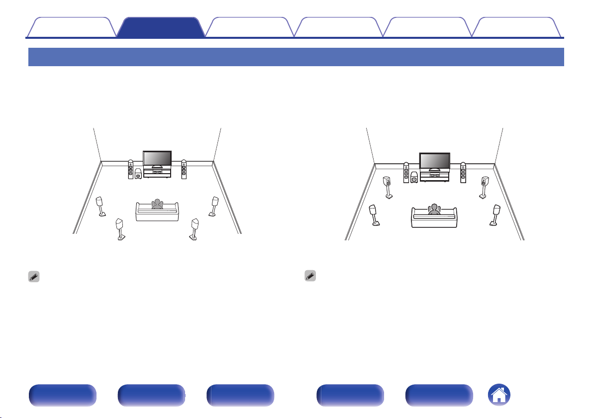
Example layout when using surround back
speakers
This 7.1-channel surround system is basic 7.1-channel system.
(Adding surround back speakers to basic 5.1-channel system)
For each speaker connection, refer to “Connecting a power
amp” (v p. 43).
Set Speaker Layout in the menu as follows. (v p. 219)
0
1. Center: Yes
2. Surround: Yes
3. Surround Back: 2 spkrs
4. Subwoofers: 1 spkr
Front panel Display Rear panel Remote Index
o
Example layout when using front wide
speakers
This 7.1-channel surround system is the same as a basic 5.1-channel
system but with front wide speakers.
For each speaker connection, refer to “Connecting a power
amp” (v p. 43).
Set Speaker Layout in the menu as follows. (v p. 219)
0
1. Center: Yes
2. Surround: Yes
3. Front Wide: Yes
4. Subwoofers: 1 spkr
51
Page 52
FL
SW
C
SL
FR
SR
FHL FHR
Contents Connections Playback Settings Tips Appendix
o
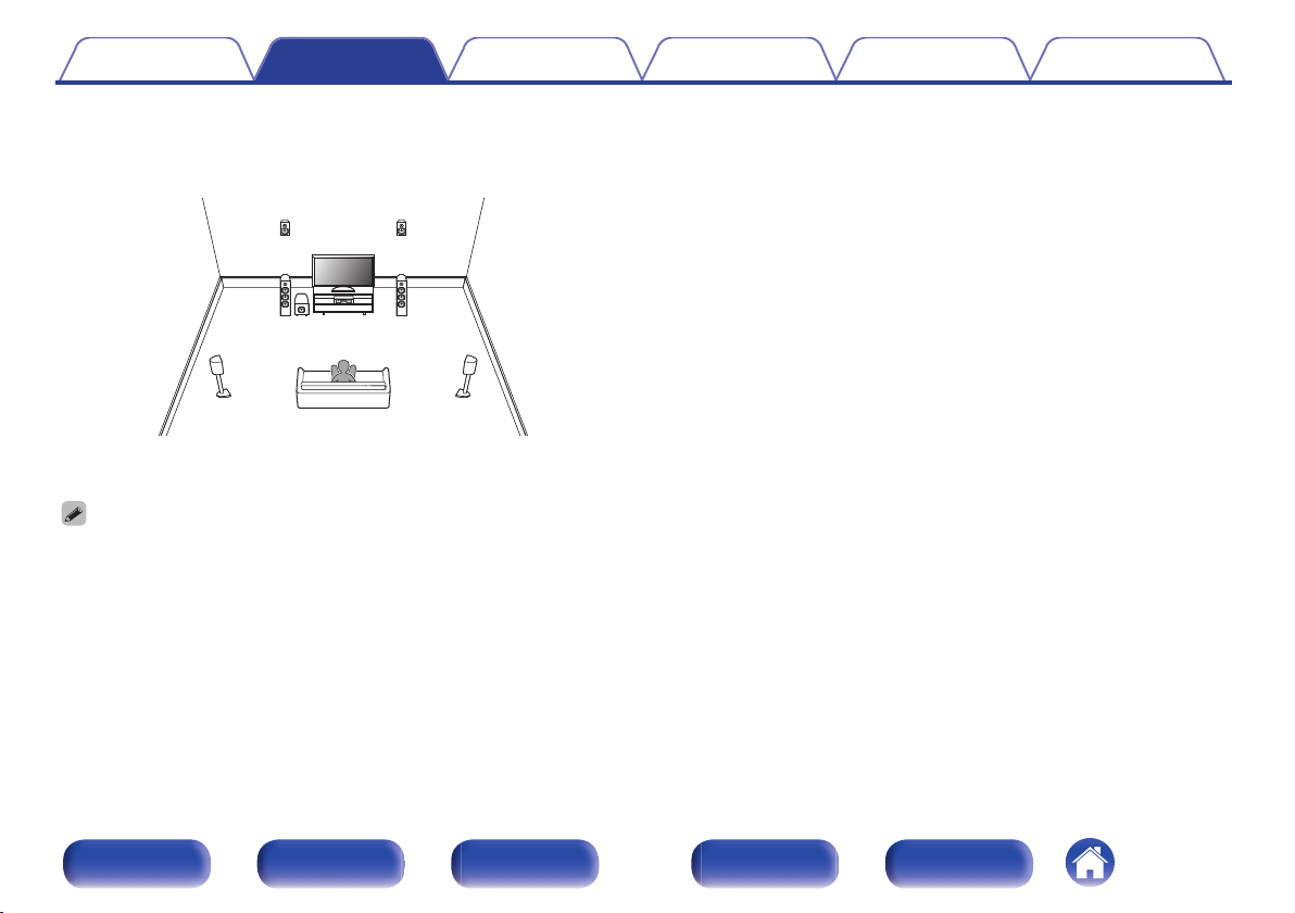
Example layout when using height speakers
This 7.1-channel surround system is the same as a basic 5.1-channel
system but with front height speakers.
For each speaker connection, refer to “Connecting a power
amp” (v p. 43).
Set Speaker Layout in the menu as follows. (v p. 219)
0
1. Center: Yes
2. Surround: Yes
3. Height Speakers: 2 spkrs
4.
Layout: Front Heightz
5. Subwoofers: 1 spkr
The front height speakers can be changed to other height, ceiling or Dolby
z
Atmos Enabled speakers in the “Speaker Layout” - “Layout” settings.
Front panel Display Rear panel Remote Index
52
Page 53
FL
SW C
SL
FR
SR
SBRSBL
FWL FWR
C
FL FR
SBL
SBR
SW
SL SR
FHL FHR
Contents Connections Playback Settings Tips Appendix
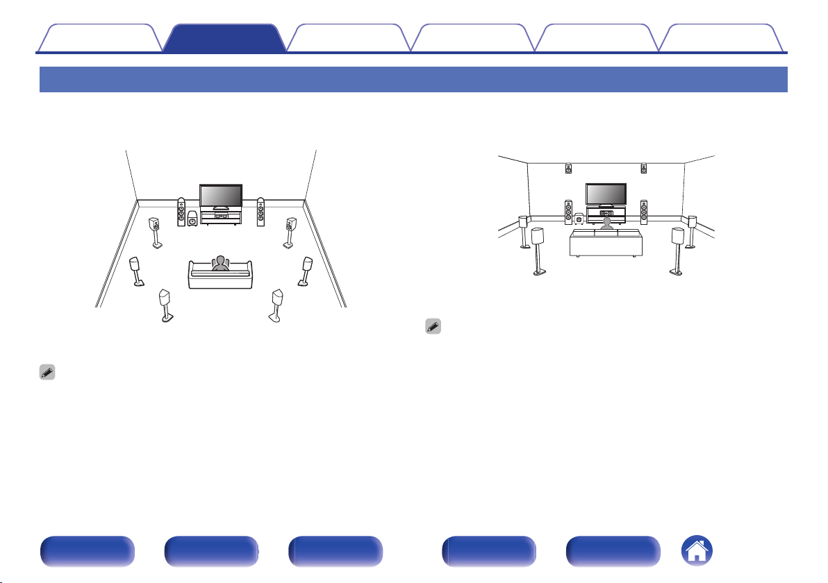
Connecting 9.1-channel speakers
o
Example layout when using surround back
and front wide speakers
o
Example layout when using surround back
and one set of height speakers
For each speaker connection, refer to “Connecting a power
amp” (v p. 43).
For each speaker connection, refer to “Connecting a power
amp” (v p. 43).
Set Speaker Layout in the menu as follows. (v p. 219)
0
1. Center: Yes
2. Surround: Yes
3. Surround Back: 2 spkrs
4. Front Wide: Yes
5. Subwoofers: 1 spkr
Front panel Display Rear panel Remote Index
Set Speaker Layout in the menu as follows. (v p. 219)
0
1. Center: Yes
2. Surround: Yes
3. Surround Back: 2 spkrs
4. Height Speakers: 2 spkrs
5.
Layout: Front Heightz
6. Subwoofers: 1 spkr
The front height speakers can be changed to other height, ceiling or Dolby
z
Atmos Enabled speakers in the “Speaker Layout” - “Layout” settings.
53
Page 54
C
FL FR
SW
SL SR
FHL FHR
FWL FWR
C
FL FR
SW
SL SR
FHL FHR
RHL RHR
Contents Connections Playback Settings Tips Appendix
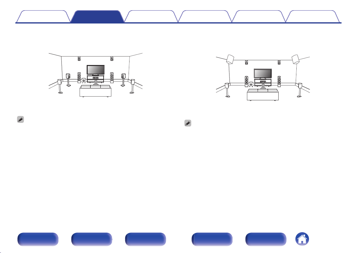
o
Example layout when using front wide and one
set of height speakers
For each speaker connection, refer to “Connecting a power
amp” (v p. 43).
Set Speaker Layout in the menu as follows. (v p. 219)
0
1. Center: Yes
2. Surround: Yes
3. Front Wide: Yes
4. Height Speakers: 2 spkrs
5.
Layout: Front Heightz
6. Subwoofers: 1 spkr
The front height speakers can be changed to other height, ceiling or Dolby
z
Atmos Enabled speakers in the “Speaker Layout” - “Layout” settings.
o
Example layout when using two sets of height
speakers
For each speaker connection, refer to “Connecting a power
amp” (v p. 43).
Set Speaker Layout in the menu as follows. (v p. 219)
0
1. Center: Yes
2. Surround: Yes
3. Height Speakers: 4 spkrs
4.
Front Layout: Front Heightz
5.
Rear Layout: Rear Heightz
6. Subwoofers: 1 spkr
The front height speakers and rear height speakers can be changed to other
z
height, ceiling or Dolby Atmos Enabled speakers in the “Speaker Layout” “Layout” settings.
Front panel Display Rear panel Remote Index
54
Page 55
FL FR
SW
SL SR
C
FHL FHR
SHL SHR
FR FL C SR SL
FHR
SW1
FHL SHR SHL
Contents Connections Playback Settings Tips Appendix
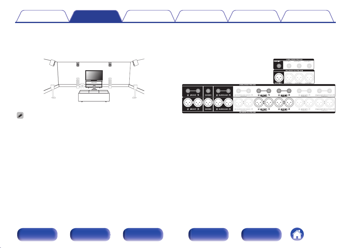
Example layout for AURO-3D 9.1 channel system
o
This speaker configuration is optimized for AURO-3D playback.
Set Speaker Layout in the menu as follows. (v p. 219)
0
1. Center: Yes
2. Surround: Yes
3. Height Speakers: 4 spkrs
4. Front Layout: Front Height
5. Rear Layout: Surround Height
6. Subwoofers: 1 spkr
Front panel Display Rear panel Remote Index
55
Page 56
C
FL FR
SW
RSLS
FHL FHR
FWL FWR
SBL
SBR
C
FL FR
SBL
SBR
SW
SL SR
FHL FHR
RHL RHR
Contents Connections Playback Settings Tips Appendix
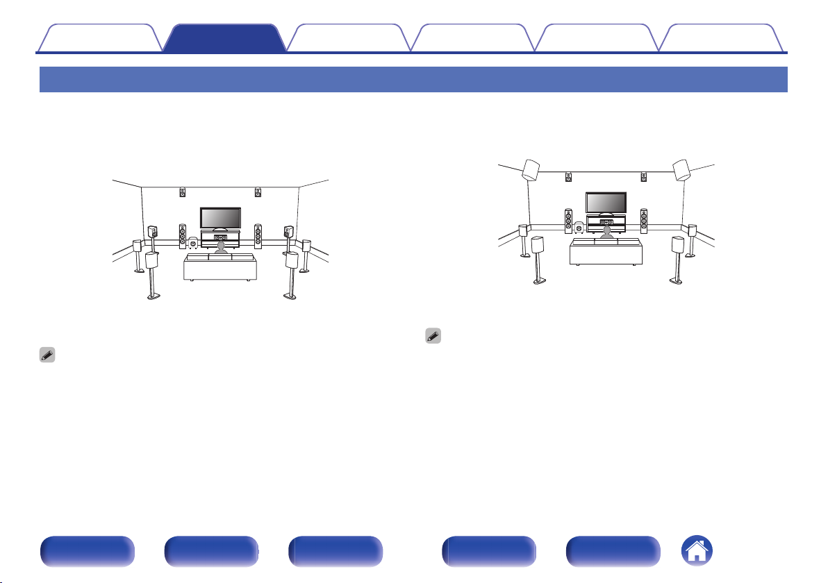
Connecting 11.1-channel speakers
o
Example layout when using surround back,
Front Wide and one set of height speakers
For each speaker connection, refer to “Connecting a power
amp” (v p. 43).
Set Speaker Layout in the menu as follows. (v p. 219)
0
1. Center: Yes
2. Surround: Yes
3. Surround Back: 2 spkrs
4. Front Wide: Yes
5. Height Speakers: 2 spkrs
6.
Layout: Front Heightz
7. Subwoofers: 1 spkr
The front height speakers can be changed to other height, ceiling or Dolby
z
Atmos Enabled speakers in the “Speaker Layout” - “Layout” settings.
o
Example layout when using surround back
and two sets of height speakers
For each speaker connection, refer to “Connecting a power
amp” (v p. 43).
Set Speaker Layout in the menu as follows. (v p. 219)
0
1. Center: Yes
2. Surround: Yes
3. Surround Back: 2 spkrs
4. Height Speakers: 4 spkrs
5.
Front Layout: Front Heightz
6.
Rear Layout: Rear Heightz
7. Subwoofers: 1 spkr
The front height speakers and rear height speakers can be changed to other
z
height, ceiling or Dolby Atmos Enabled speakers in the “Speaker Layout” “Layout” settings.
Front panel Display Rear panel Remote Index
56
Page 57
C
FL FR
SW
RSLS
FHL FHR
RHL RHR
FWL FWR
C
FL FR
SW
RSLS
TML TMR
FHL FHR
RHL RHR
Contents Connections Playback Settings Tips Appendix
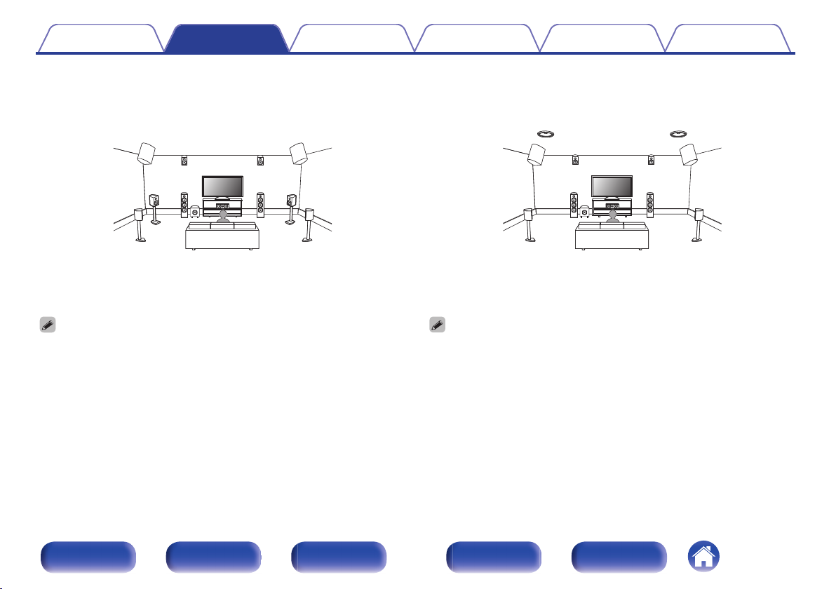
o
Example layout when using front wide and two
sets of height speakers
For each speaker connection, refer to “Connecting a power
amp” (v p. 43).
Set Speaker Layout in the menu as follows. (v p. 219)
0
1. Center: Yes
2. Surround: Yes
3. Front Wide: Yes
4. Height Speakers: 4 spkrs
5.
Front Layout: Front Heightz
6.
Rear Layout: Rear Heightz
7. Subwoofers: 1 spkr
The front height speakers and rear height speakers can be changed to other
z
height, ceiling or Dolby Atmos Enabled speakers in the “Speaker Layout” “Layout” settings.
o
Example layout when using three sets of
height speakers
For each speaker connection, refer to “Connecting a power
amp” (v p. 43).
Set Speaker Layout in the menu as follows. (v p. 219)
0
1. Center: Yes
2. Surround: Yes
3. Height Speakers: 6 spkrs
4.
Front Layout: Front Heightz
5.
Middle Layout: Top Middlez
6.
Rear Layout: Rear Heightz
7. Subwoofers: 1 spkr
The front height speakers, top middle speakers and rear height speakers can be
z
changed to other height, ceiling or Dolby Atmos Enabled speakers in the
“Speaker Layout” - “Layout” settings.
Front panel Display Rear panel Remote Index
57
Page 58
FL FR
SW
SRSL
C
FHL FHR
CH
SHL SHR
TS
FR FL C SR SL
FHR
SW1
FHL SHR SHL
CH TS
Contents Connections Playback Settings Tips Appendix
o
Example layout for AURO-3D 11.1 channel
system
This speaker configuration is optimized for AURO-3D playback.
For each speaker connection, refer to “Connecting a power
amp” (v p. 43).
Set Speaker Layout in the menu as follows. (v p. 219)
0
1. Center: Yes
2. Surround: Yes
3. Height Speakers: 6 spkrs
4. Front Layout: Front Height
5. Middle Layout: Surround Height
6. Rear Layout: No
7. TS/CH: TS/CH
8. Subwoofers: 1 spkr
Front panel Display Rear panel Remote Index
58
Page 59
C
FL FR
SW
RSLS
FHL FHR
RHL RHR
FWL FWR
SBL
SBR
C
FL FR
SBL
SBR
SW
RSLS
TML TMR
FHL FHR
RHL RHR
Contents Connections Playback Settings Tips Appendix
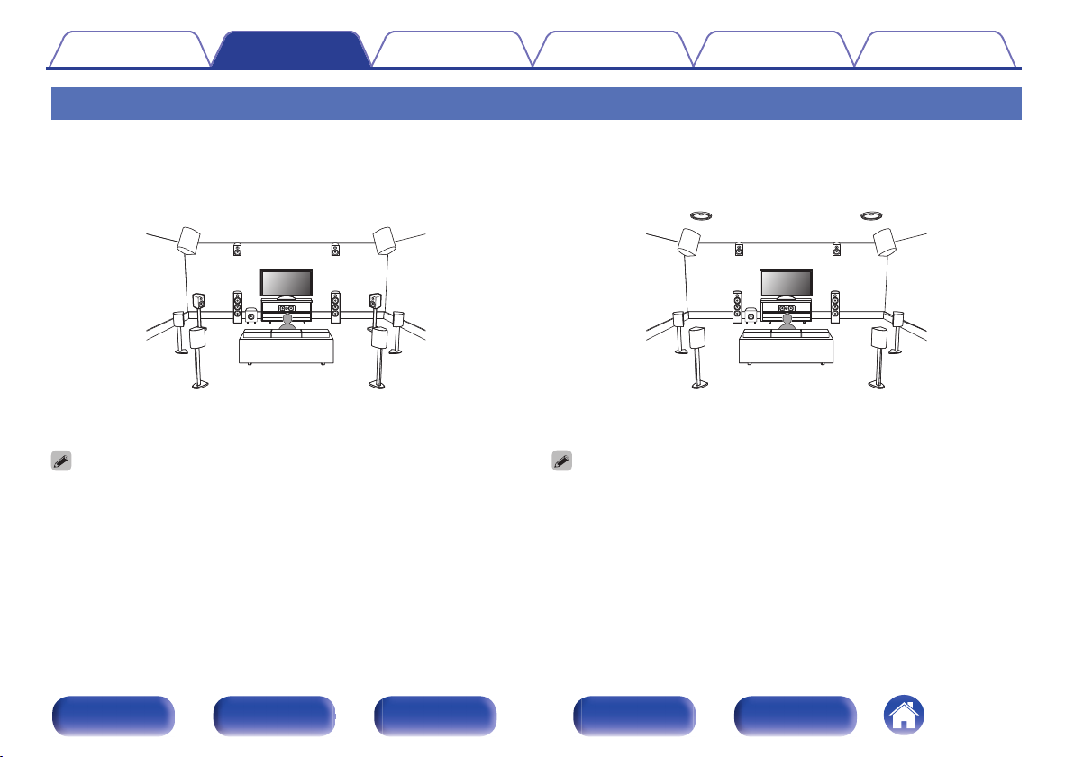
Connecting 13.1-channel speakers
o
Example layout when using surround back,
Front Wide and two set of height speakers
For each speaker connection, refer to “Connecting a power
amp” (v p. 43).
Set Speaker Layout in the menu as follows. (v p. 219)
0
1. Center: Yes
2. Surround: Yes
3. Surround Back: 2 spkrs
4. Front Wide: Yes
5. Height Speakers: 4 spkrs
6. Front Layout: Front Height
7. Rear Layout: Rear Height
8. Subwoofers: 1 spkr
o
Example layout when using surround back
and three sets of height speakers
For each speaker connection, refer to “Connecting a power
amp” (v p. 43).
Set Speaker Layout in the menu as follows. (v p. 219)
0
1. Center: Yes
2. Surround: Yes
3. Surround Back: 2 spkrs
4. Height Speakers: 6 spkrs
5. Front Layout: Front Height
6. Middle Layout: Top Middle
7. Rear Layout: Rear Height
8. Subwoofers: 1 spkr
Front panel Display Rear panel Remote Index
59
Page 60
C
FL FR
SW
RSLS
FHL FHR
RHL RHR
FWL FWR
SHL SHR
Contents Connections Playback Settings Tips Appendix
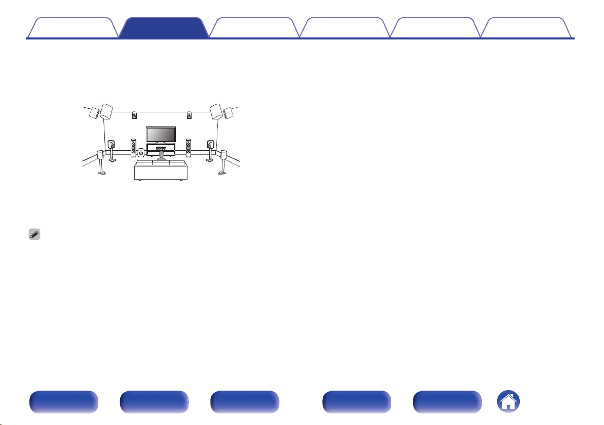
o
Example layout when using front wide and
three sets of height speakers
For each speaker connection, refer to “Connecting a power
amp” (v p. 43).
Set Speaker Layout in the menu as follows. (v p. 219)
0
1. Center: Yes
2. Surround: Yes
3. Surround Back: No
4. Front Wide: Yes
5. Height Speakers: 6 spkrs
6. Front Layout: Front Height
7. Middle Layout: Surround Height
8. Rear Layout: Rear Height
9. Subwoofers: 1 spkr
Front panel Display Rear panel Remote Index
60
Page 61
FL FR
SW
SRSL
C
FHL FHR
CH
SHL SHR
TS
SBRSBL
FR FL C SR SL
FHR
SW1
FHLSBR SBL SHR SHL
CH TS
Contents Connections Playback Settings Tips Appendix
o
Example layout for AURO-3D 13.1 channel
system
This speaker configuration is optimized for AURO-3D playback.
For each speaker connection, refer to “Connecting a power
amp” (v p. 43).
Set Speaker Layout in the menu as follows. (v p. 219)
0
1. Center: Yes
2. Surround: Yes
3. Surround Back: 2 spkrs
4. Height Speakers: 6 spkrs
5. Front Layout: Front Height
6. Middle Layout: Surround Height
7. Rear Layout: No
8. TS/CH: TS/CH
9. Subwoofers: 1 spkr
Front panel Display Rear panel Remote Index
61
Page 62
TML TMR
C
SW
RSLS
RHL RHR
SBL
SBR
FHL FHR
FL FR
CH
TS
Contents Connections Playback Settings Tips Appendix
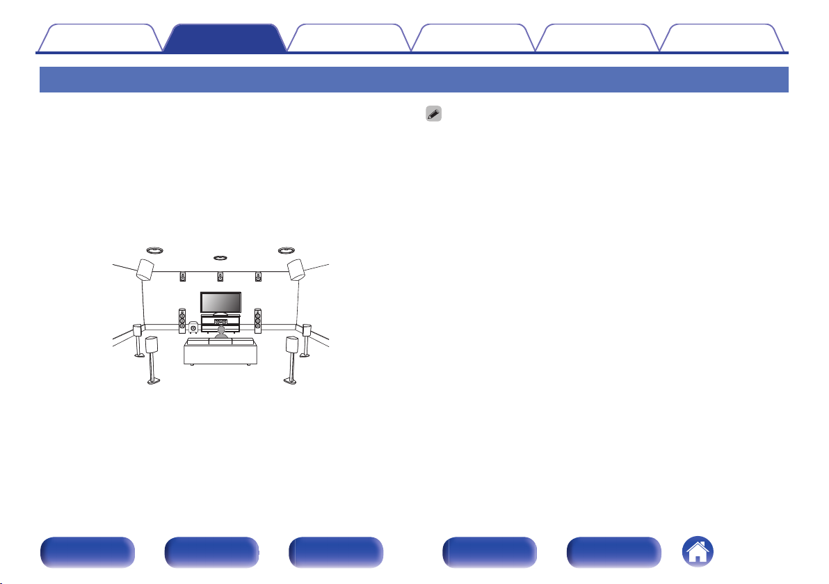
Connecting 15.1-channel speakers
o
Example layout when using surround back
and eight height speakers
This system can connect with up to 15.1-channel speakers and
simultaneously play up to 13.1-channels for Dolby Atmos and
AURO-3D playback.
The top middle speakers, top surround speaker, and center height
speaker are switched and played according to the audio format you
are playing.
For each speaker connection, refer to “Connecting a power
amp” (v p. 43).
Set Speaker Layout in the menu as follows. (v p. 219)
0
1. Center: Yes
2. Surround: Yes
3. Surround Back: 2 spkrs
4. Front Wide: No
5. Height Speakers: 8 spkrs
6. Front Layout: Front Height
7. Middle Layout: Top Middle
8. Rear Layout: Rear Height
9. TS/CH: TS/CH
10.Subwoofers: 1 spkr
Front panel Display Rear panel Remote Index
62
Page 63
C
SW
RSLS
FHL FHR
RHL RHR
SBL
SBR
FL
(Bi-Amp) (Bi-Amp)
FR
z
2
z1z
1
z
2
z2z
2
SW1
SR SLC RHR RHL
FHR FHL
SBLSBR
FLFR
(R) (L)
wqwq
Marantz
AMP 20
Marantz
AMP 20
Second unit
Contents
Connections Playback Settings Tips Appendix
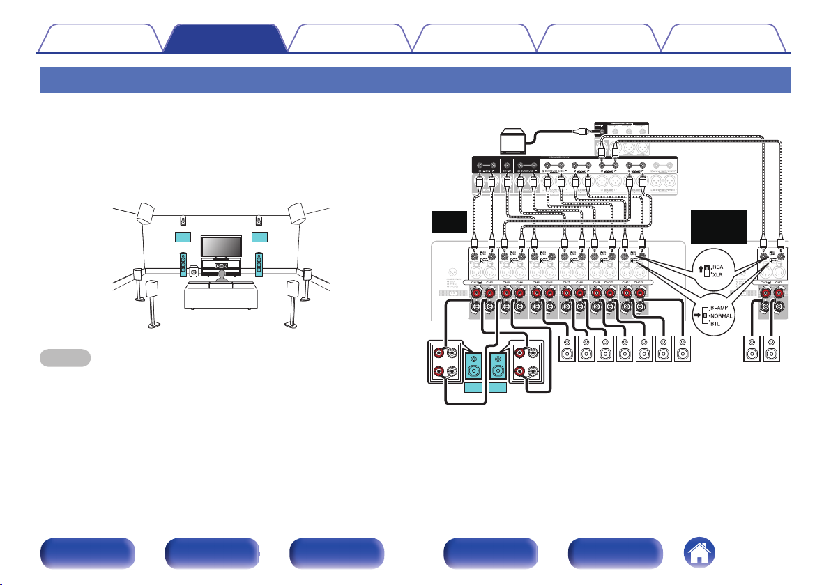
Connecting 11.1-channel speakers: Bi-amp connection of front speakers
This system plays back 11.1-channels. You can use the bi-amp
connection for front speakers. Bi-amp connection is a method to connect
separate amplifiers to the tweeter terminal and woofer terminal of a
speaker that supports bi-amplification. This connection enables back EMF
(power returned without being output) from the woofer to flow into the
tweeter without affecting the sound quality, producing a higher sound
quality.
NOTE
When making bi-amp connections, be sure to remove the short-circuiting plate or
0
wire between the speaker’s woofer and tweeter terminals.
Front panel Display Rear panel Remote Index
z1
z2
63
GExampleH UNBALANCED RCA connector connection
The PRE OUT connectors for a bi-amp connection vary depending on the
MAIN ZONE layout. Refer to “Speaker Layout” in the menu. (v p. 219)
The height speakers, ceiling speakers and Dolby Atmos Enabled speakers
can be connected to the HEIGHT1, HEIGHT2 and HEIGHT3 RCA connectors
or HEIGHT1, HEIGHT2 and HEIGHT3 XLR connectors. Set the speaker to be
connected from “Speaker Layout” in the menu. (v p. 219)
Page 64
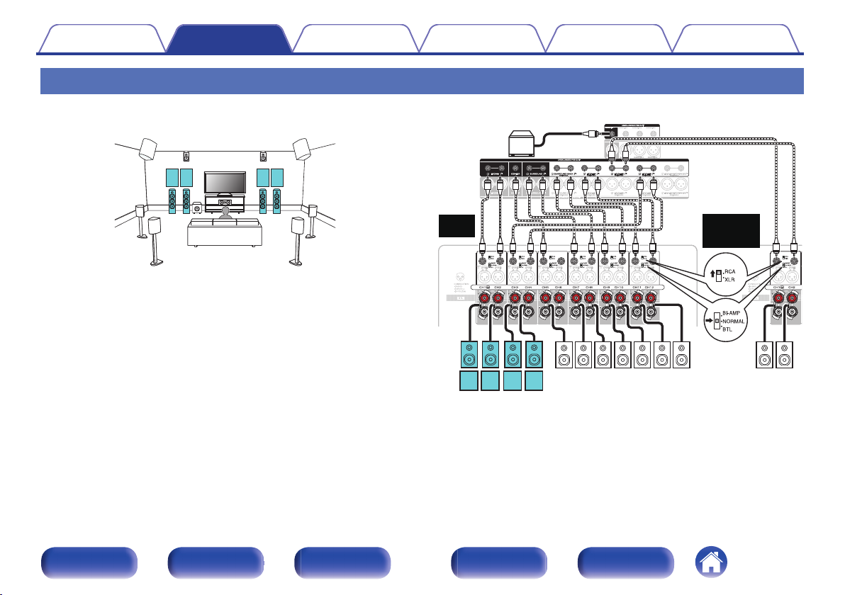
C
SW
RSLS
FHL FHR
RHL RHR
SBL
SBR
FL
(A)FL(B)
FR
(B)FR(A)
z
2
z1z
1
z
2
z2z
2
SW1
SR SLC RHR RHL
FHR FHL
SBLSBR
FR
(A)FL(A)FR(B)FL(B)
Marantz
AMP 20
Marantz
AMP 20
Second unit
Contents
Connections Playback Settings Tips Appendix
Connecting 11.1-channel speakers: Second pair of front speakers
This system enables switching playback between front speakers A and B
as desired.
GExampleH UNBALANCED RCA connector connection
Front panel Display Rear panel Remote Index
The PRE OUT connectors for connecting to the second front speakers vary
z1
depending on the main zone layout. Refer to “Speaker Layout” in the menu.
(v p. 219)
The height speakers, ceiling speakers and Dolby Atmos Enabled speakers
z2
can be connected to the HEIGHT1, HEIGHT2 and HEIGHT3 RCA connectors
or HEIGHT1, HEIGHT2 and HEIGHT3 XLR connectors. Set the speaker to be
connected from “Speaker Layout” in the menu. (v p. 219)
64
Page 65
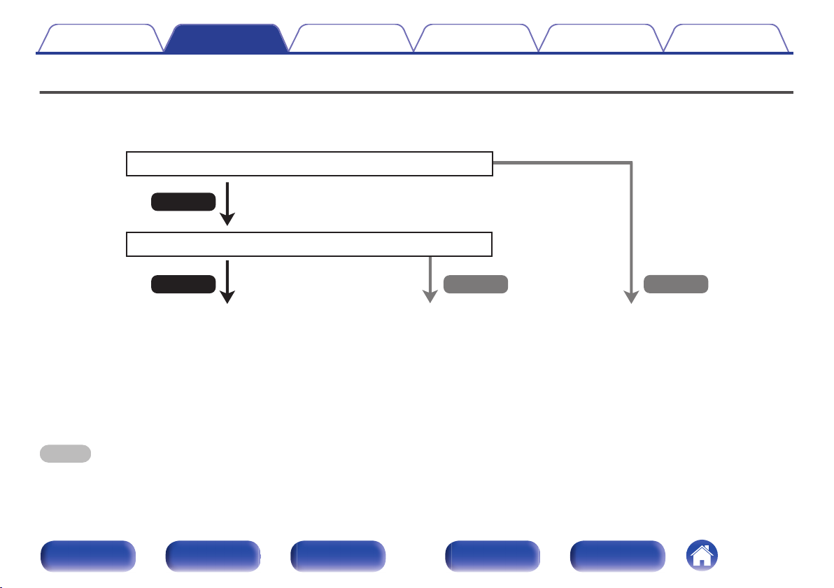
No
Yes
Is the TV equipped with an HDMI connector?
Yes No
Is the TV compatible with the ARC / eARC?
z
Contents Connections Playback Settings Tips Appendix
Connecting a TV
Connect a TV to this unit so that the input video is output to the TV. You can also enjoy audio from the TV on this unit.
How to connect a TV depends on the connectors and functions equipped on the TV.
“Connection 1 : TV equipped with an HDMI
connector and compatible with the ARC /
eARC” (v p. 66)
What is ARC and eARC?
z
ARC (Audio Return Channel) sends audio back to this unit using the same HDMI cable that sends video from this unit to your TV.
This allows this unit to process the sound from your TV’s built-in tuner and apps.
TVs with eARC (Enhanced Audio Return Channel) port provide additional support for high bitrate multichannel audio (Dolby Atmos, Dolby TrueHD, DTS-HD and DTS:X).
Please refer to your TV Owner’s Manual for details about eARC support for your particular model.
NOTE
Use a TV with a 2 prong power plug for this unit. Do not connect a TV with a 3 prong power plug, as this may cause noise.
0
“Connection 2 : TV equipped with an HDMI
connector and incompatible with the ARC /
eARC” (v p. 67)
You cannot connect the TV to this
unit.
Front panel Display Rear panel Remote Index
65
Page 66
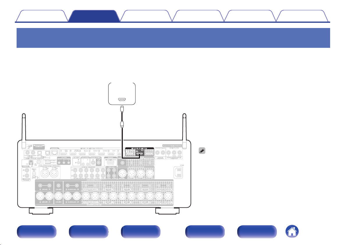
(ARC / eARC)
IN
HDMI
TV
Contents Connections Playback Settings Tips Appendix
Connection 1 : TV equipped with an HDMI connector and compatible with the ARC /
eARC
Using a high quality HDMI cablez, connect one end to the HDMI port labeled “eARC” or “ARC” on your TV. Connect the other end to the HDMI OUT TV 1
port on this unit.
When a TV with eARC support is connected, the eARC function of this unit is enabled automatically and the television audio is played back. When a TV
with ARC support is connected, set “ARC” in the menu to “On”. (v p. 195)
For 4K TVs we recommend using an HDMI cable labeled “High Speed”
z
and “with Ethernet”.
For 8K TVs we recommend using an HDMI cable labeled “Ultra High
z
Speed”.
eARC function settings may be required depending on the eARC
0
function-compatible television you are using. Make sure eARC is set to
on if this setting exists on your television. For more information, check
your television’s owner’s manual.
Set “4K/8K Signal Format” to “8K Enhanced” in the menu to enjoy 8K
0
video. (v p. 201)
Front panel Display Rear panel Remote Index
66
Page 67
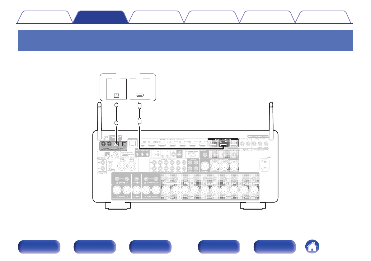
OUT
OPTICAL
OUT IN
IN
HDMI
TV
Contents Connections Playback Settings Tips Appendix
Connection 2 : TV equipped with an HDMI connector and incompatible with the
ARC / eARC
Use an HDMI cable to connect the TV to this unit.
To listen to audio from TV on this unit, use an optical cable to connect the TV to this unit.
Front panel Display Rear panel Remote Index
67
Page 68
Contents Connections Playback Settings Tips Appendix
Connecting a playback device
This unit is equipped with three types of video input connectors (HDMI, component video and composite video) and three types of audio input connectors
(HDMI, digital audio and audio).
Select input connectors on this unit according to the connectors equipped on the device you want to connect.
If the device connected to this unit is equipped with an HDMI connector, it is recommended to use HDMI connections.
In the HDMI connection, audio and video signals can be transmitted through a single HDMI cable.
“Connecting a set-top box (Satellite tuner/cable TV)” (v p. 70)
0
“Connecting a media player” (v p. 71)
0
“Connecting a Blu-ray Disc player or DVD player” (v p. 72)
0
“Connecting a game console or player device compatible with 8K” (v p. 73)
0
“Connecting a turntable” (v p. 74)
0
Connect devices to this unit as indicated by the input sources printed on the audio/video input connectors of this unit.
0
The source that is assigned to the HDMI IN, DIGITAL AUDIO IN, COMPONENT VIDEO IN, VIDEO IN and AUDIO IN connectors can be changed. See “Input Assign” on how
0
to change the input source assigned to the input connectors. (v p. 203)
To play back audio signals that are input to this unit on a TV connected via HDMI, set in the menu “HDMI Audio Out” to “TV”. (v p. 193)
0
To enjoy content that is copyright protected by HDCP 2.2 or HDCP 2.3, use a playback device and TV compatible with HDCP 2.2 or HDCP 2.3.
0
Front panel Display Rear panel Remote Index
68
Page 69
2
1
3
Contents Connections Playback Settings Tips Appendix
Connecting the BALANCED XLR IN connector
o
This unit is equipped with BALANCED XLR IN connectors. Use these connectors if your device has an XLR connector as an audio output connector.
When using BALANCED XLR IN connectors, assign “XLR” for “Input Assign” – “ANALOG”. (v p. 204)
By default, these connectors are disabled.
GAV 20 BALANCED XLR IN connector PIN arrangementH
GND (Ground)
A
HOT (+)
B
COLD (–)
C
Front panel Display Rear panel Remote Index
69
Page 70
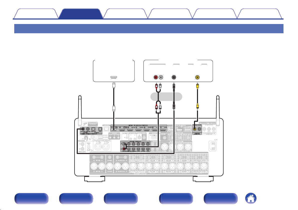
R
L
R
L
OUT
HDMI
OUT
COAXIAL
AUDIO
AUDIO
RL
OUT
OUT
VIDEO
VIDEO
or
Satellite tuner /
Cable TV
Satellite tuner /
Cable TV
(HDMI incompatible device)
Contents Connections Playback Settings Tips Appendix
Connecting a set-top box (Satellite tuner/cable TV)
This explanation uses the connection with a satellite tuner/cable TV STB as an example.
Select the input connectors on this unit to match the connectors on the device that you want to connect to.
Front panel Display Rear panel Remote Index
70
Page 71
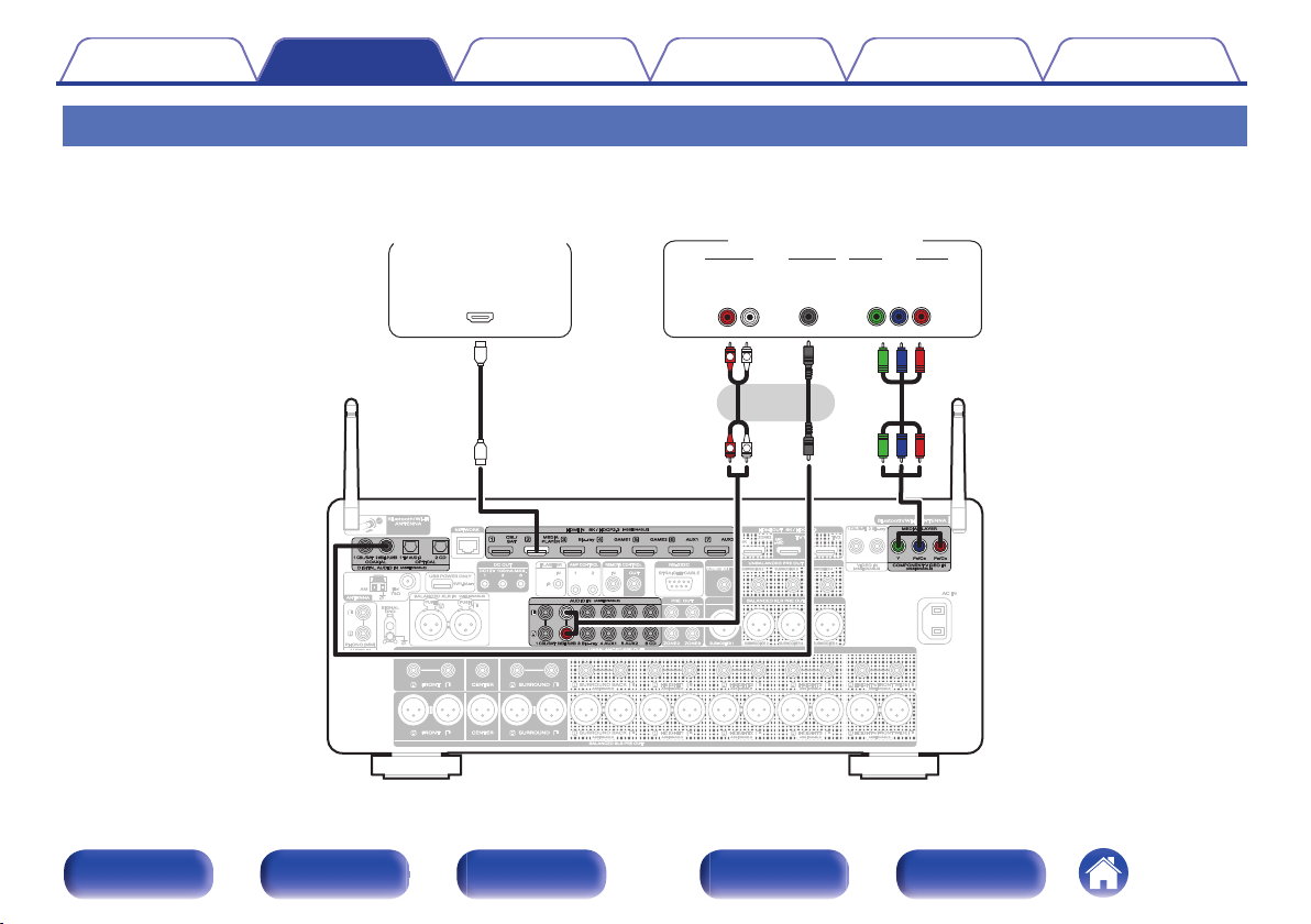
R
L
R
L
OUT
HDMI
AUDIO VIDEO
AUDIO
RL
OUT
OUT
COAXIAL
OUT
COMPONENT VIDEO
YPB PR
or
(HDMI incompatible device)
Media playerMedia player
Contents Connections Playback Settings Tips Appendix
Connecting a media player
This explanation uses the connection with a media player as an example.
Select the input connectors on this unit to match the connectors on the device that you want to connect to.
Front panel Display Rear panel Remote Index
71
Page 72
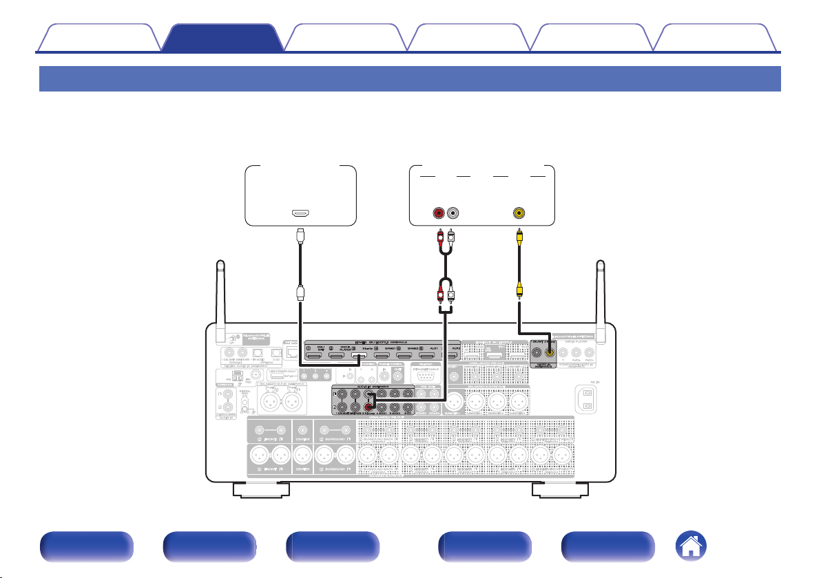
R
L
R
L
OUT
HDMI
OUT
VIDEO
VIDEO
AUDIO
AUDIO
RL
OUT
Blu-ray Disc player /
DVD player
Blu-ray Disc player /
DVD player
(HDMI incompatible device)
Contents Connections Playback Settings Tips Appendix
Connecting a Blu-ray Disc player or DVD player
This explanation uses the connection with a Blu-ray Disc player or DVD player as an example.
Select the input connectors on this unit to match the connectors on the device that you want to connect to.
Front panel Display Rear panel Remote Index
72
Page 73
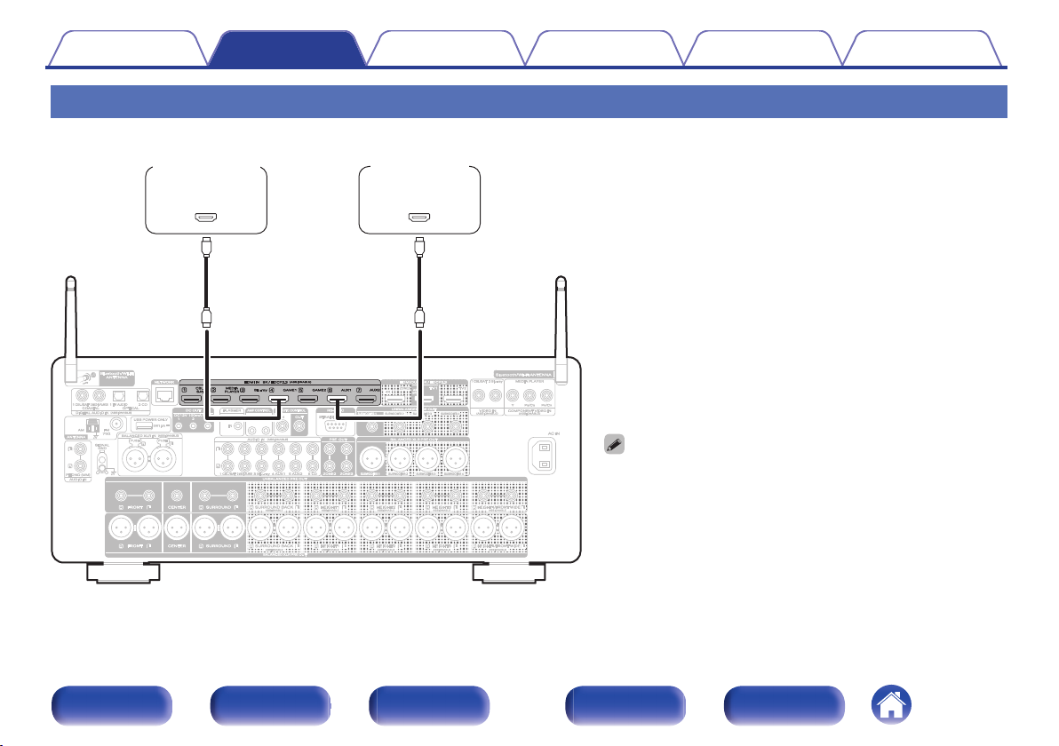
OUT
HDMI
OUT
HDMI
Game console 8K player
Contents
Connections Playback Settings Tips Appendix
Connecting a game console or player device compatible with 8K
This unit supports 8K HDMI video signals.
Use a certified “Ultra High Speed HDMI cable” to enjoy 8K or 4K
0
120Hz video.
Set “4K/8K Signal Format” to “8K Enhanced” in the menu to enjoy 8K
0
video. (v p. 201)
Front panel Display Rear panel Remote Index
73
Page 74
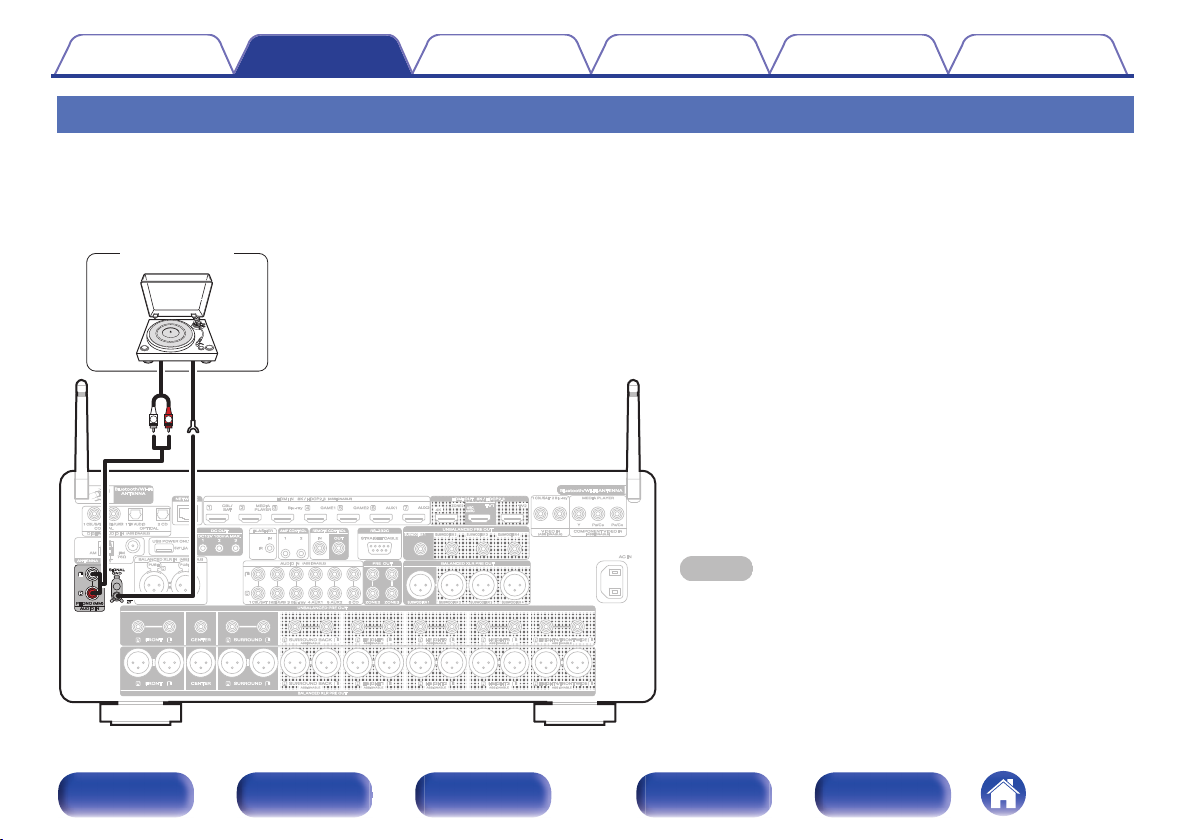
GND
AUDIO
OUT
L
R
(MM cartridge)
Turntable
Contents
Connections Playback Settings Tips Appendix
Connecting a turntable
This unit is compatible with turntables equipped with a moving magnet (MM) phono cartridge. When you connect to a turntable with a low output moving
coil (MC) cartridge, use a commercially available MC head amp or a step-up transformer.
If you set this unit’s input source to “Phono” and you accidentally increase the volume without having a turntable connected, you may hear a hum noise
from the speakers.
NOTE
The earth terminal (SIGNAL GND) of this unit is not for safety
0
grounding purposes. If this terminal is connected when there is a lot of
noise, the noise can be reduced. Note that depending on the turntable,
connecting the ground line may have the reverse effect of increasing
noise. In this case, it is not necessary to connect the ground line.
Front panel Display Rear panel Remote Index
74
Page 75
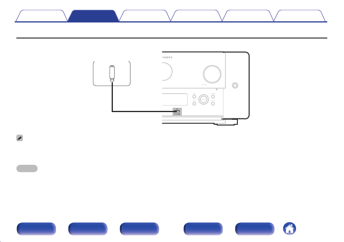
USB memory
device
Contents Connections Playback Settings Tips Appendix
Connecting a USB memory device to the USB port
For operating instructions see “Playing a USB memory device” (v p. 89).
Marantz does not guarantee that all USB memory devices will operate or receive power. When using a portable USB hard disk drive (HDD) which came with an AC adapter,
0
use that device’s supplied AC adapter.
The USB port on the rear panel can only be used to supply power (5 V/1.5 A). It cannot be used to play music files. (v p. 30)
0
NOTE
USB memory devices will not work via a USB hub.
0
It is not possible to use this unit by connecting the unit’s USB port to a PC via a USB cable.
0
Do not use an extension cable when connecting a USB memory device. This may cause radio interference with other devices.
0
Front panel Display Rear panel Remote Index
75
Page 76
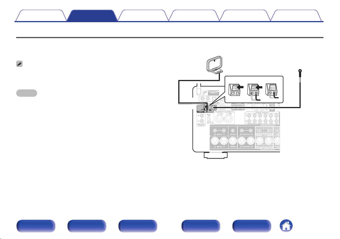
q we
Black
AM loop antenna
(supplied)
FM indoor antenna
(supplied)
White
Contents Connections Playback Settings Tips Appendix
Connecting FM/AM antennas
Connect the antenna, tune in to a broadcast and then move the antenna to
the location where there is least noise. Then use tape, etc. to fix the
antenna in this location. (“Listening to FM/AM broadcasts” (v p. 101))
If you are unable to receive a good broadcast signal, we recommend installing an
0
outdoor antenna. For details, inquire at the retail store where you purchased the
unit.
NOTE
Make sure the AM loop antenna lead terminals do not touch metal parts of the
0
panel.
Front panel Display Rear panel Remote Index
76
Page 77
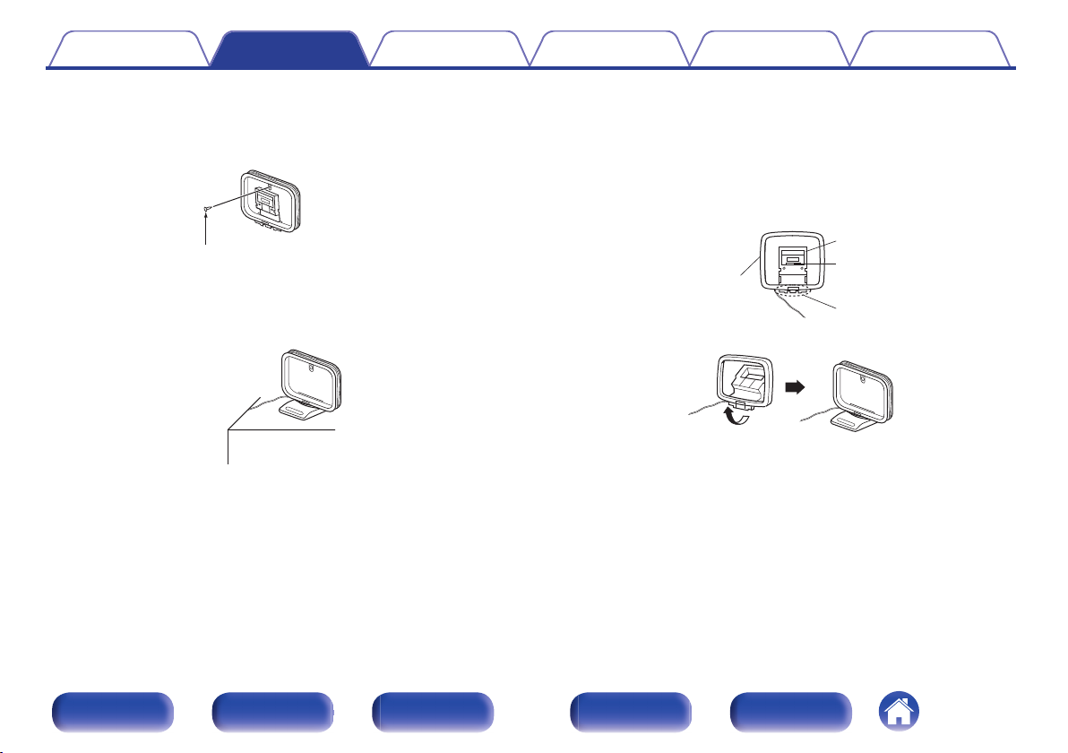
Nail, tack, etc.
Projecting part
Square hole
Stand
Loop antenna
Contents Connections Playback Settings Tips Appendix
o
Using the AM loop antenna
Suspending on a wall
Suspend directly on a wall without assembling.
Standing alone
Use the procedure shown above to assemble.
When assembling, refer to “AM loop antenna assembly”.
o
AM loop antenna assembly
Put the stand section through the bottom of the loop
1
antenna from the rear and bend it forward.
Insert the projecting part into the square hole in the
2
stand.
Front panel Display Rear panel Remote Index
77
Page 78
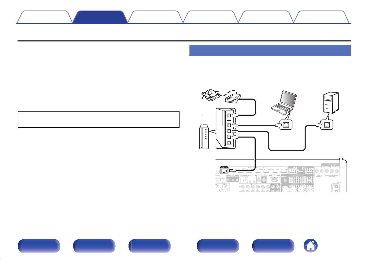
Internet
Modem
PC
Router
To WAN side
To LAN port
To LAN port
NAS
(Network Attached
Storage)
LAN port /
Ethernet
connector
LAN port /
Ethernet
connector
Contents Connections Playback Settings Tips Appendix
Connecting to a home network (LAN)
This unit can connect to a network using a wired LAN or wireless LAN.
You can connect this unit to your home network (LAN) to enable various
types of playback and operations as described below.
Playback of network audio such as Internet Radio and from your media
0
server(s)
Playback of streaming music services
0
Using the Apple AirPlay function
0
Operation on this unit via the network
0
Operation with the HEOS wireless multi-room sound system
0
Firmware Update
0
For connections to the Internet, contact an ISP (Internet Service
Provider) or a computer shop.
Wired LAN
To make connections via wired LAN, use a LAN cable to connect the
router to this unit as shown in the figure below.
Front panel Display Rear panel Remote Index
78
Page 79
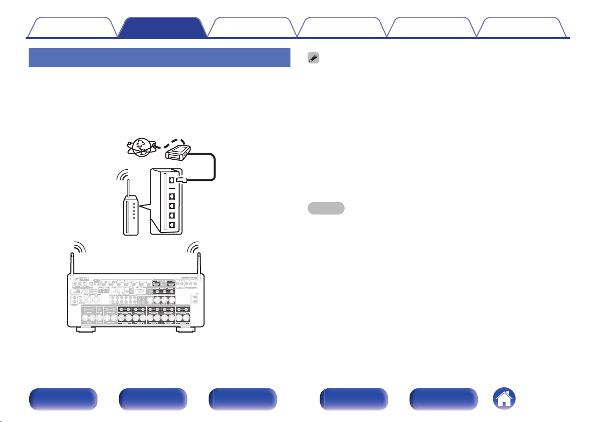
Internet
Modem
Router with access point
To WAN side
Contents Connections Playback Settings Tips Appendix
Wireless LAN
When using this unit, we recommend you use a router equipped with the following
When connecting to the network via wireless LAN, connect the external
antennas for Bluetooth/wireless connectivity connection to the rear panel
and stand them upright.
See “Wi-Fi Setup” on how to connect to a wireless LAN router.
(v p. 246)
0
functions:
Built-in DHCP server
0
This function automatically assigns IP addresses on the LAN.
Built-in 100BASE-TX switch
0
When connecting multiple devices, we recommend a switching hub with a
speed of 100 Mbps or greater.
Only use a shielded STP or ScTP LAN cable (readily available at electronics
0
stores). (CAT-5 or greater recommended)
The normal shielded-type LAN cable is recommended.
0
If a flat-type cable or unshielded-type cable is used, other devices could be
affected by noise.
When using this unit connected to a network with no DHCP function, configure the
0
IP address, etc. in “Network”. (v p. 245)
NOTE
The types of routers that can be used depend on the ISP. Contact your ISP or a
0
computer shop for details.
This unit is not compatible with PPPoE. A PPPoE compatible router is required if
0
your contracted line is not set using PPPoE.
Do not connect a NETWORK connector directly to the LAN port / Ethernet
0
connector on your computer.
Various online services may be discontinued without prior notice.
0
Front panel Display Rear panel Remote Index
79
Page 80
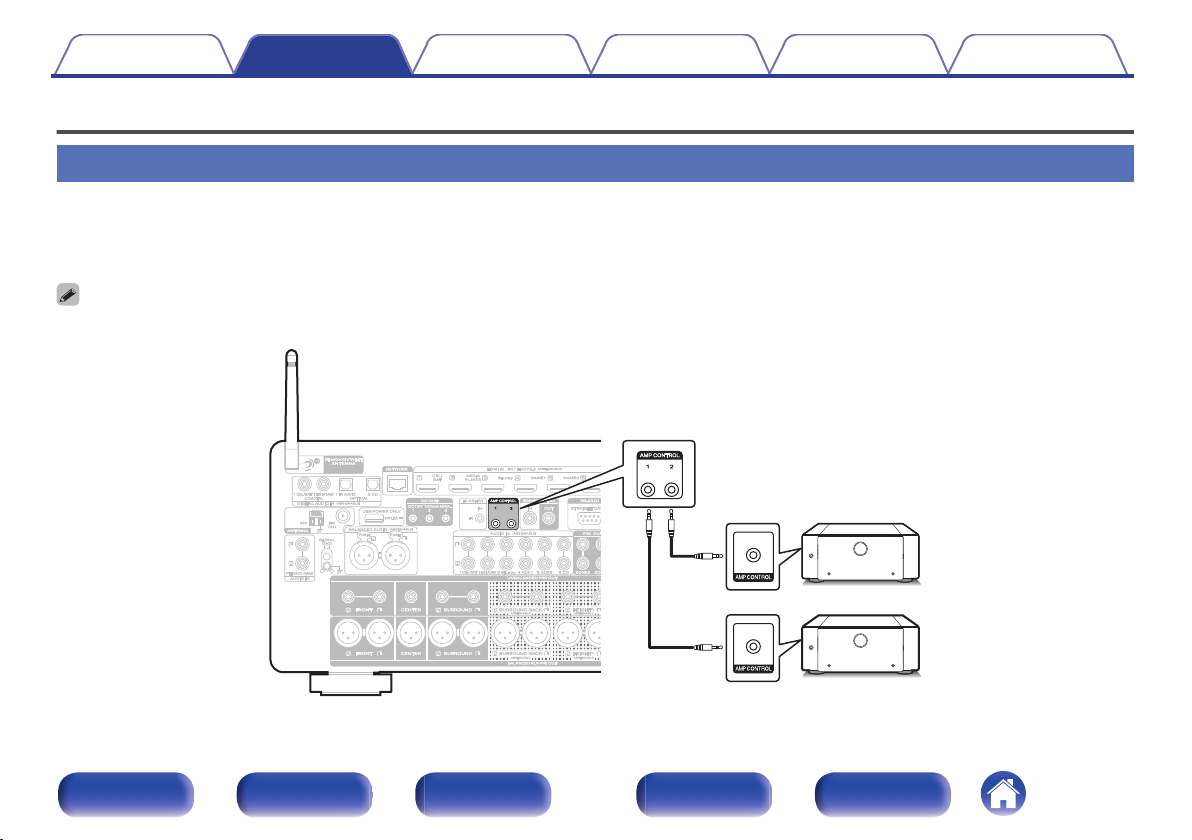
Contents Connections Playback Settings Tips Appendix
Connecting an external control device
AMP CONTROL jacks
If you connect Marantz power amp products equipped with AMP CONTROL jacks using a control cable (supplied with the power amp), you can perform
the following linked operations.
Link the power of the power amp to the on/standby operation of this unit.
0
Link the display brightness of the power amp to the display brightness setting operation of this unit.
0
Up to two power amps can be connected. For the connection method, see the Owner’s Manual for the power amp.
0
Front panel Display Rear panel Remote Index
80
Page 81
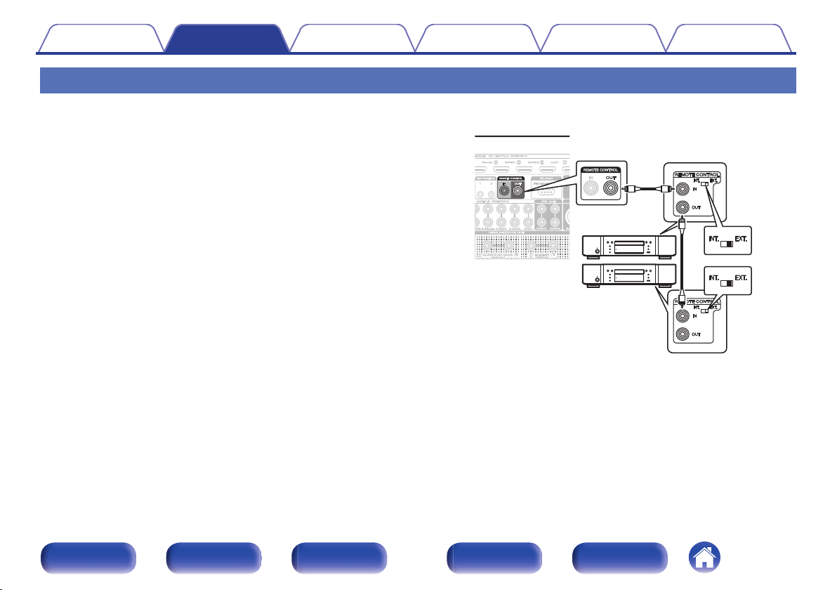
Contents
Connections Playback Settings Tips Appendix
REMOTE CONTROL jacks
If the remote control jack of this unit is connected with the remote control terminal of a Marantz device, the connected device can be controlled with the
remote as a single system.
o
When controlling a connected device from this
unit
Connect the REMOTE CONTROL OUT jack of this unit to the
0
REMOTE CONTROL IN jack of the device to be connected.
Point the remote control operations towards this unit. The
0
transmitted infrared signal from the remote control is received by the
remote control infrared receiver of this unit and is sent to the other
devices through the remote control jack.
If there is a remote control switch on the back of the device to be
0
connected with this unit, set it to “EXTERNAL” or “EXT.”.
If you connect the Marantz power amp (including Hi-Fi amplifier) to
0
any of these terminals, the power of the power amp operates in
conjunction with the power of this unit.
Front panel Display Rear panel Remote Index
81
Page 82
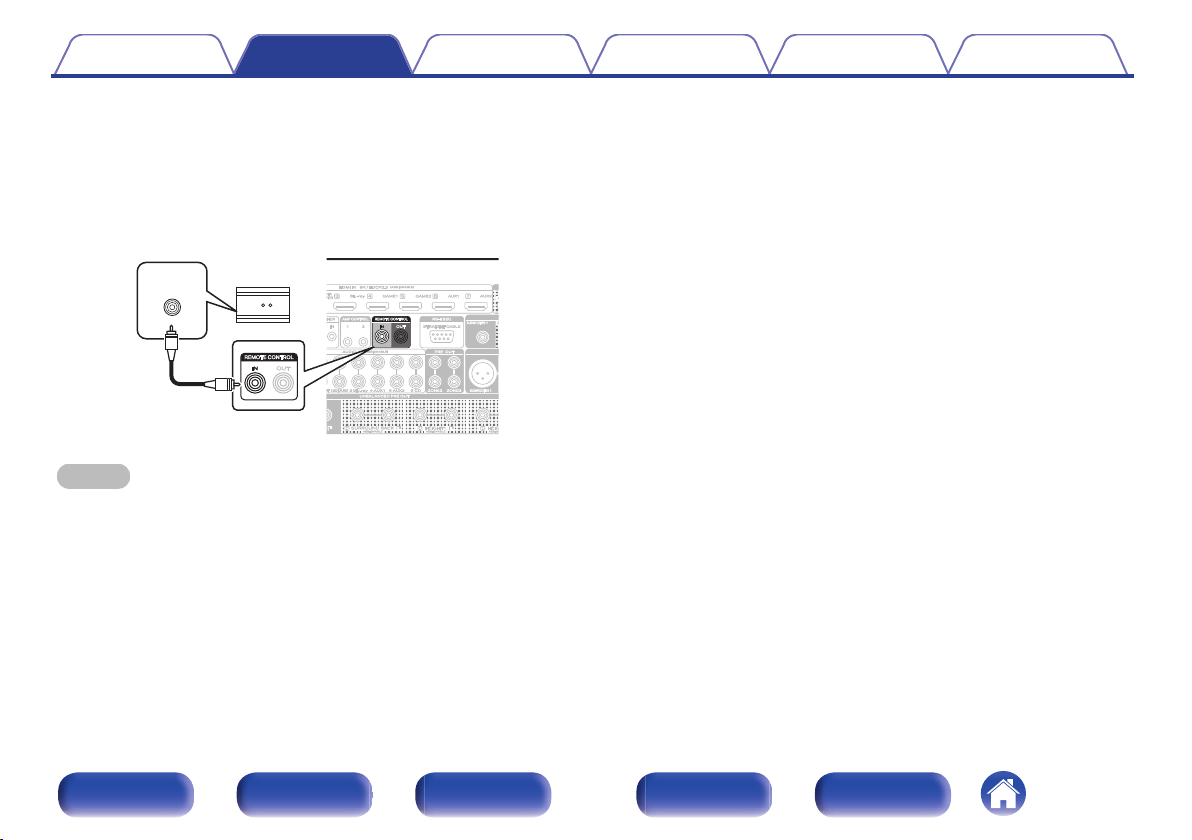
RC OUT
IR receiver
Contents Connections Playback Settings Tips Appendix
o
When controlling this unit from a connected
device
Connect to the REMOTE CONTROL IN jack of this unit from the
0
REMOTE CONTROL OUT jack of the device to be connected.
If you perform this operation, disable the remote sensor function of
0
this unit using the “Remote lock function”. (v p. 160)
NOTE
When the remote control signal receiving function is disabled, you can not perform
0
operations with the remote control unit.
Front panel Display Rear panel Remote Index
82
Page 83
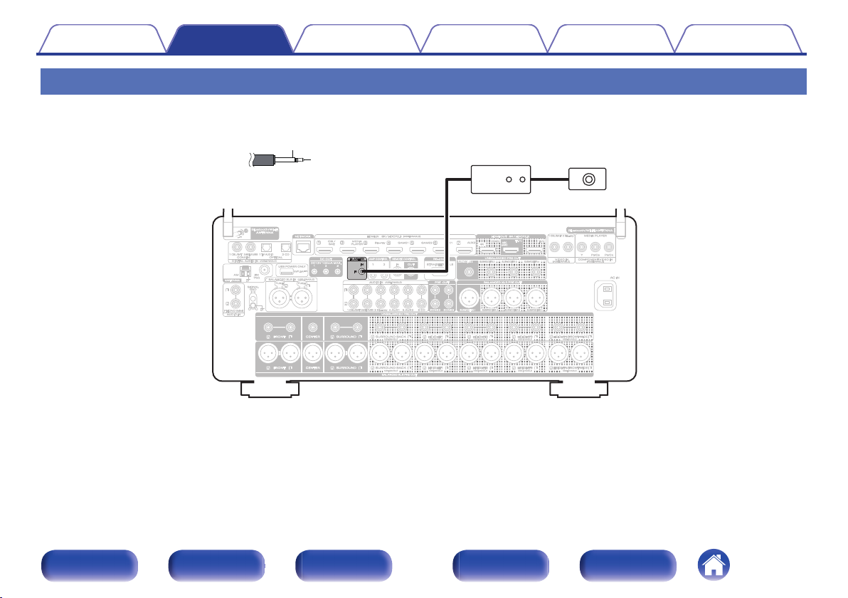
GND
Signal
Monaural mini-plug cable
(Sold separately)
IR repeater IR receiver
Contents Connections Playback Settings Tips Appendix
FLASHER IN jack
If a commercially available (sold separately) IR repeater is connected to the FLASHER IN jack of this unit, remote control operations can be performed
even if this unit is installed in a place where the remote control signal may not reach, such as in a cabinet.
Front panel Display Rear panel Remote Index
83
Page 84
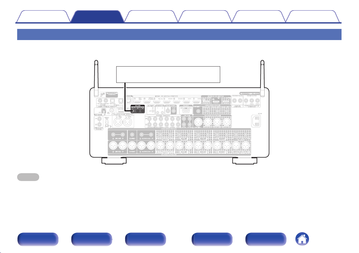
12 V DC/100 mA trigger-compatible device
Contents
Connections Playback Settings Tips Appendix
DC OUT jacks
When a device with DC IN jack is connected, the connected device’s power on/standby can be controlled through linked operation to this unit.
A digital signal of a maximum of 12V DC/100mA (total 300mA) per jack will be output from the DC OUT jack.
NOTE
Use a monaural mini-plug cable for connecting the DC OUT jacks. Do not use a stereo mini-plug cable.
0
If the permissible trigger input level for the connected device is larger than 12 V DC/100 mA, or has shorted, the DC OUT jack cannot be used. In this case, turn off the power
0
to the unit, and disconnect it.
Front panel Display Rear panel Remote Index
84
Page 85
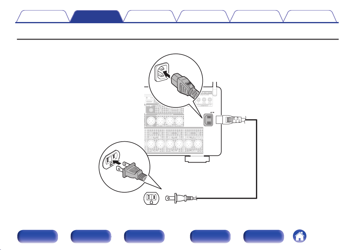
(AC 120 V, 60 Hz)
To household power outlet
Power cord (supplied)
Contents Connections Playback Settings Tips Appendix
Connecting the power cord
After completing all the connections, insert the power plug into the power outlet.
Front panel Display Rear panel Remote Index
85
Page 86
Contents Connections Playback Settings Tips Appendix
o
Contents
Basic operation
Turning the power on 87
Selecting the input source 87
Adjusting the volume 88
Turning off the sound temporarily (Muting) 88
Selecting a sound mode 137
Playback a device
Playing a Blu-ray Disc player/DVD player 88
Playing a USB memory device 89
Listening to music on a Bluetooth device 93
Listening to audio on Bluetooth headphones 97
Listening to FM/AM broadcasts 101
Playback network audio/service
Listening to Internet Radio 109
Playing back files stored on a PC or NAS 111
Getting the HEOS App 115
AirPlay function 123
Spotify Connect function 126
Convenience functions
Convenience functions 127
HDMI Control function 151
Sleep timer function 152
Smart select function 154
Panel lock function 158
Remote lock function 160
Other functions
Web control function 161
Playback in ZONE2/ZONE3 (Another room) 163
Front panel Display Rear panel Remote Index
86
Page 87
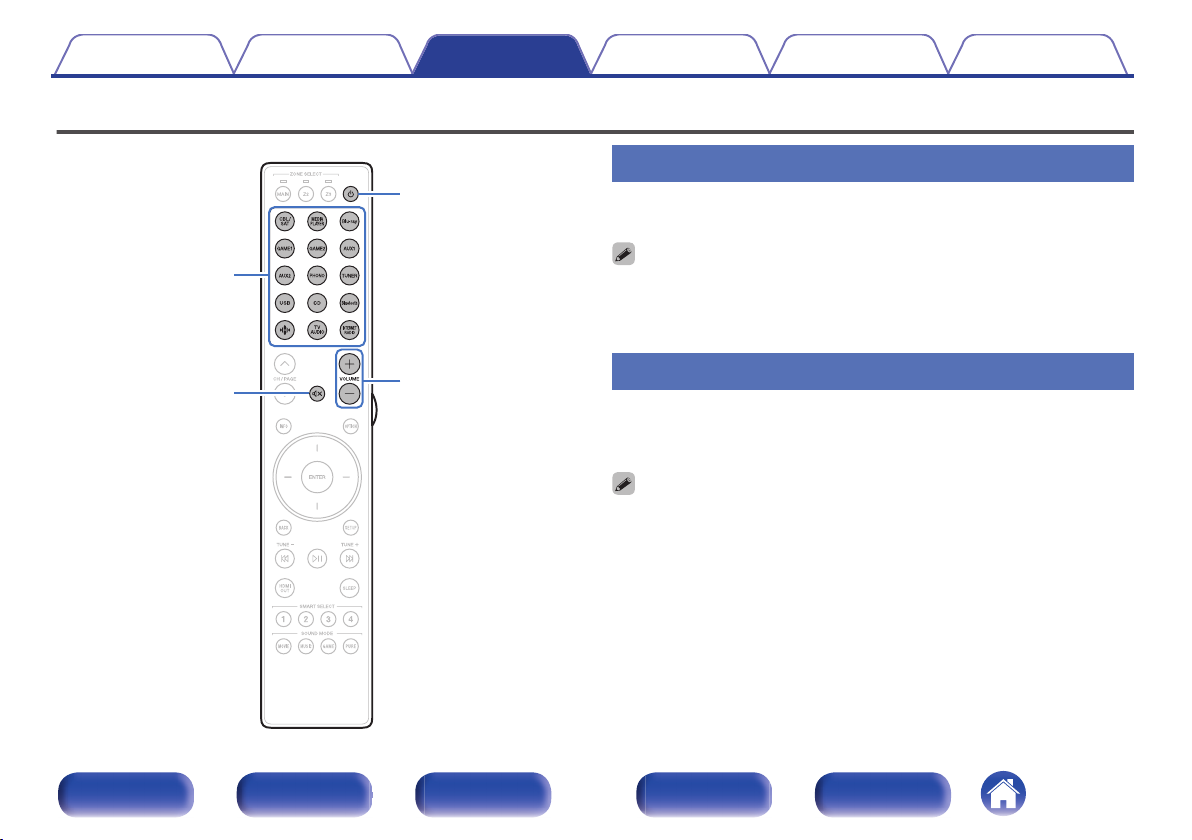
VOLUME
no
X
:
Input source
select buttons
Contents Connections Playback Settings Tips Appendix
Basic operation
Turning the power on
Press POWER X to turn on power to the unit.
1
You can press the input source select button when the unit is in standby mode to
0
turn on the power.
You can also switch the power to standby by pressing X on the main unit.
0
Front panel Display Rear panel Remote Index
Selecting the input source
Press the input source select button to be played back.
1
The desired input source can be selected directly.
You can also select the input source by turning INPUT selector on the main unit.
0
87
Page 88
Contents Connections Playback Settings Tips Appendix
Adjusting the volume
Use VOLUME no to adjust the volume.
1
The variable range differs according to the input signal and channel level setting.
0
You can also adjust the master volume by turning VOLUME on the main unit.
0
Turning off the sound temporarily
(Muting)
Press MUTE :.
1
“MUTE” appears on the display.
0
h appears on the TV screen.
0
The sound is reduced to the level set at “Mute Level” in the menu. (v p. 186)
0
To cancel mute, either adjust the sound volume or press MUTE : again.
0
If h is displayed on the TV screen for more than 5 minutes when the “Screen
0
Saver” is set to “On”, the h symbol moves randomly over the TV screen.
(v p. 200)
Playback a Blu-ray Disc player/DVD
player
The following describes the procedure for playing Blu-ray Disc player/DVD
player.
Prepare for playback.
1
Turn on the power of the TV, subwoofer and player.
A
Change the TV input to the input of this unit.
B
Press POWER X to turn on power to the unit.
2
Press Blu-ray or DVD to switch an input source for a
3
player used for playback.
Play the Blu-ray Disc player or DVD player.
4
o
Surround playback (v p. 137)
Front panel Display Rear panel Remote Index
88
Page 89
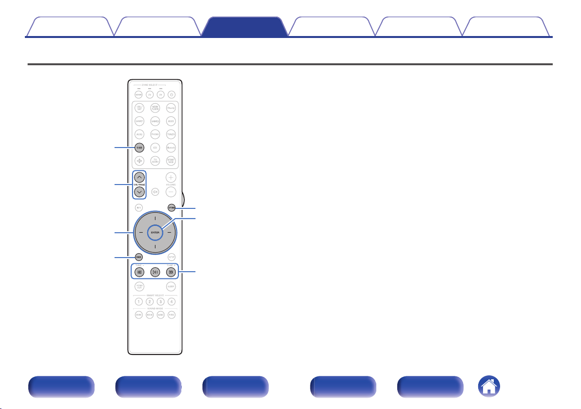
OPTION
ENTER
BACK
USB
CH/PAGE
ml
p
k j
Cursor Up/Down/
Left/Right
Contents
Connections Playback Settings Tips Appendix
Playing a USB memory device
Playing back music files stored on a USB memory device.
0
Only USB memory devices conforming to mass storage class standards
0
can be played on this unit.
This unit is compatible with USB memory devices in “FAT32” or “NTFS”
0
format.
The audio format types and specifications supported by this unit for
0
playback are as follows.
See “Playing back a USB memory devices” (v p. 304) for details.
WMA
0
MP3
0
WAV
0
MPEG-4 AAC
0
FLAC
0
Apple Lossless
0
DSD
0
Front panel Display Rear panel Remote Index
89
Page 90
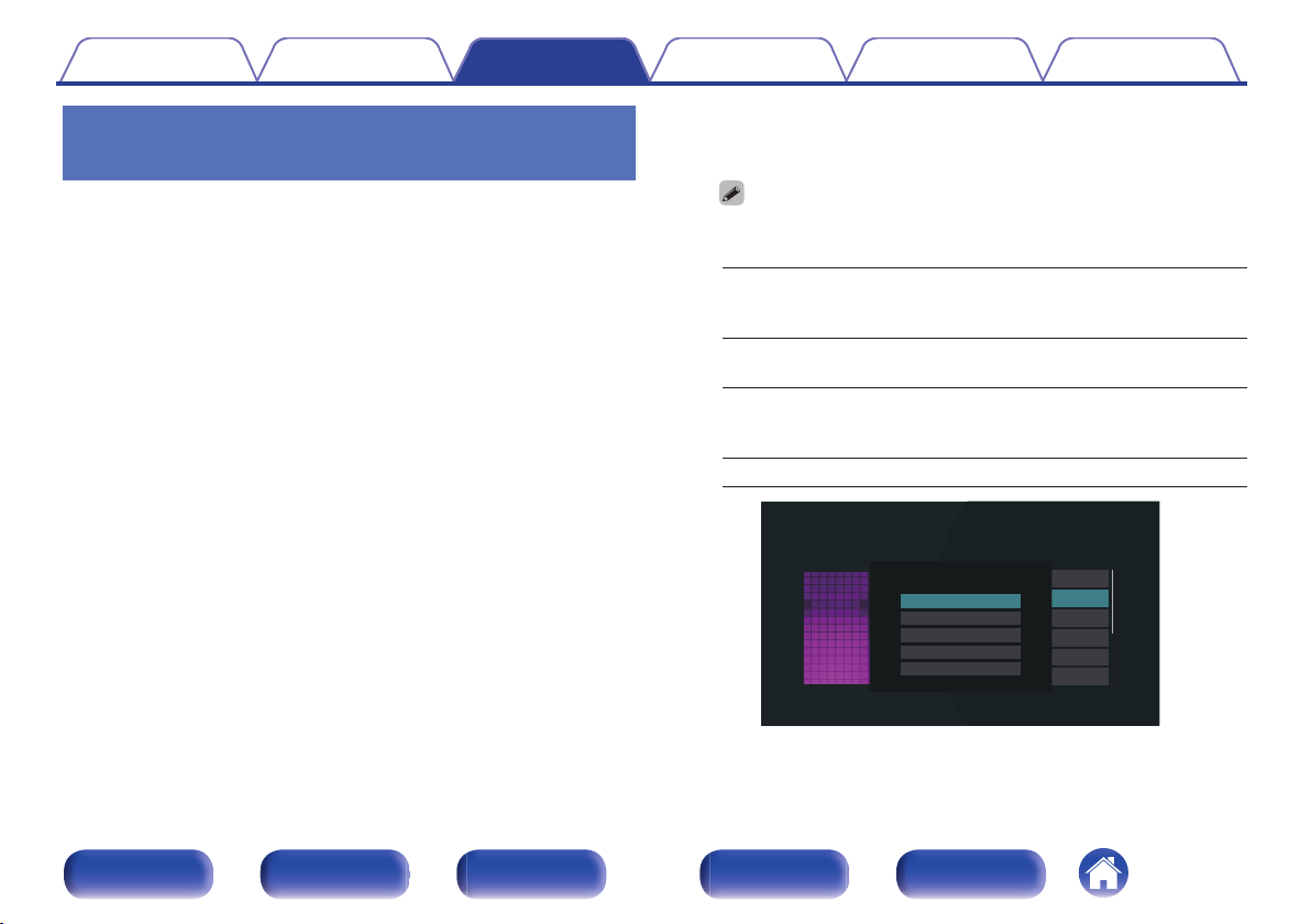
Nature 01
USB Music - Nature
Play Now
Play Now & Replace Queue
Play Next
Add to End of Queue
Cancel
Contents Connections Playback Settings Tips Appendix
Playing files stored on USB memory
devices
Insert a “FAT32” or “NTFS” formatted USB memory
1
device into the USB port.
Press USB to switch the input source to “USB”.
2
Select the name of this unit.
3
Front panel Display Rear panel Remote Index
90
Browse the music on your USB memory device and
4
select something to play.
When you select something to play you will be asked how you want to
0
queue up your music.
Play Now:
Play Now & Replace
Queue:
Play Next:
Add to End of Queue: Adds the item to the end of the queue.
Inserts the item into the queue after the
currently playing track and plays the
selected item immediately.
Clears the queue and plays the
selected item immediately.
Inserts the item into the queue after the
current song and plays it when the
current song ends.
Page 91
2:45
-14:21
Nature
Nature 01 - Various Artists
Now Playing
Contents Connections Playback Settings Tips Appendix
5
Use cursor Up/Down to select the “Play Now” or “Play
Now & Replace Queue”, then press ENTER.
Playback starts.
Operation buttons Function
p
k j
CH/PAGE ml
When an MP3 music file includes album art data, the album art can be displayed
0
while playing the file.
Playback / Pause
Skip to previous track / Skip to next track
Switch to the previous page/next page in
the list display
NOTE
Note that Marantz will accept no responsibility whatsoever for any problems
0
arising with the data on a USB memory device when using this unit in conjunction
with the USB memory device.
When a USB memory device is connected to this unit, the unit loads all of the files
0
on the USB memory device. Loading may take a while if the USB memory device
contains a large number of folders and/or files.
Front panel Display Rear panel Remote Index
91
Page 92
Contents
o
Operations accessible through the option
Connections Playback Settings Tips Appendix
menu
“Adjusting the audibility of dialog and vocals (Dialog
0
Enhancer)” (v p. 129)
“Adjusting the volume of each channel to match the input source
0
(Channel Level Adjust)” (v p. 130)
“Adjusting the tone (Tone)” (v p. 131)
0
“Adjusting audio delay (Audio Delay)” (v p. 132)
0
“Changing the strength of Tactile Transducer according to the input
0
source (Tactile Transducer)” (v p. 133)
“Displaying your desired video during audio playback (Video
0
Select)” (v p. 134)
“Playing the same music in all zones (All Zone Stereo)” (v p. 135)
0
“Changing the speaker settings to match the listening environment
0
(Speaker Preset)” (v p. 136)
Changing the “Dirac Live Filter”
0
https://manuals.marantz.com/DiracLive/ALL/EN/DRDZSYktvnhzad.php
Front panel Display Rear panel Remote Index
92
Page 93
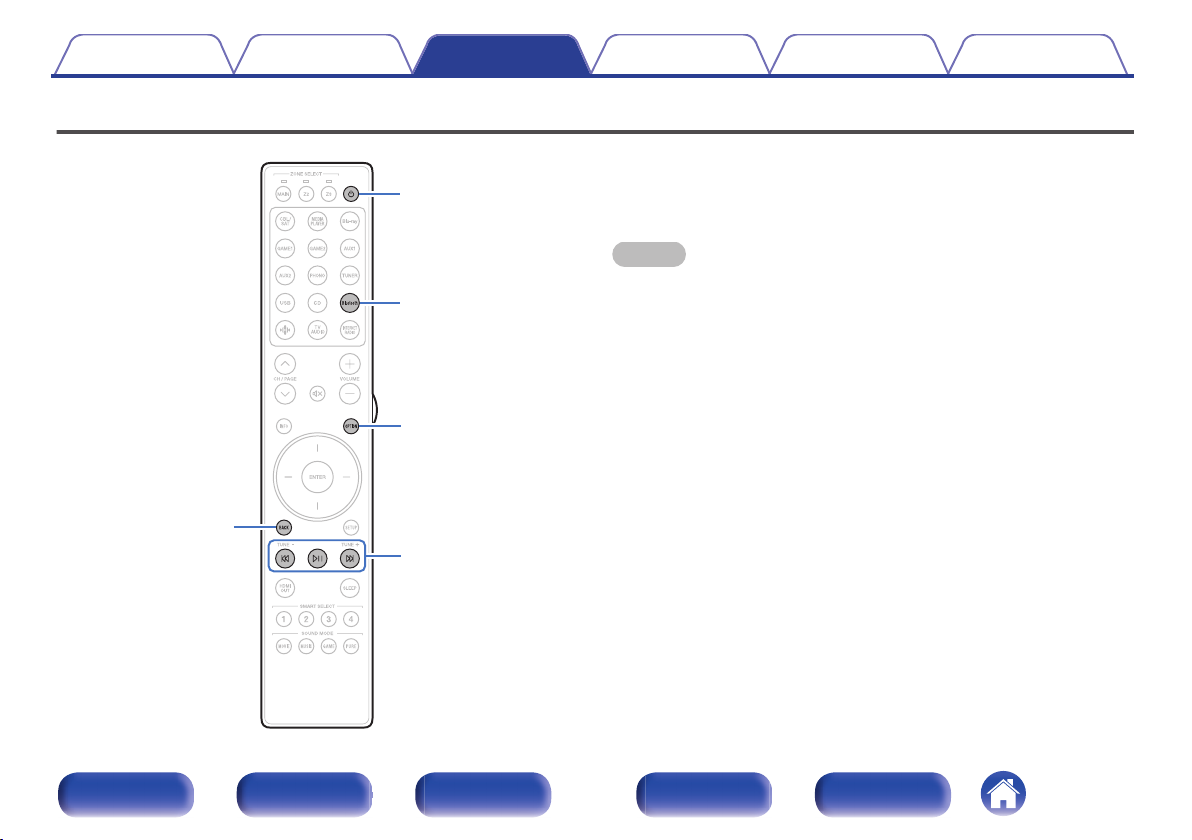
Bluetooth
X
BACK
p
k j
OPTION
Contents Connections Playback Settings Tips Appendix
Listening to music on a Bluetooth device
Music files stored on Bluetooth devices such as smartphones, digital
music players, etc. can be enjoyed on this unit by pairing and connecting
this unit with the Bluetooth device.
Communication is possible up to a range of about 98.4 ft/30 m.
NOTE
To play back music from a Bluetooth device, the Bluetooth device needs to
0
support the A2DP profile.
Front panel Display Rear panel Remote Index
93
Page 94
Contents Connections Playback Settings Tips Appendix
Playing music from Bluetooth device
In order to enjoy music from a Bluetooth device on this unit, the Bluetooth
device must first be paired with this unit.
Once the Bluetooth device has been paired, it does not need to be paired
again.
Prepare for playback.
1
Connect the supplied external antennas for Bluetooth/wireless
A
connectivity to the Bluetooth/wireless LAN antenna connectors
on the rear panel. (v p. 30)
Press POWER X to turn on power to the unit.
B
Press Bluetooth.
2
When using for the first time, the unit will go into the pairing mode
automatically and “Pairing...” will appear on the display of the unit.
Activate the Bluetooth settings on your mobile device.
3
Select this unit when its name appears in the list of
4
devices displayed on the screen of the Bluetooth
device.
Connect to the Bluetooth device while “Pairing” is being displayed
on the display of the unit.
Perform the connection with the Bluetooth device close to the unit
(about 3.3 ft/1 m).
Play music using any app on your Bluetooth device.
5
The Bluetooth device can also be operated with the remote
0
control of this unit.
The next time the Bluetooth button is pressed on the remote
0
control unit, this unit automatically connects to the last Bluetooth
device that was connected.
Operation buttons
p
k j
Press STATUS on this unit during playback to switch the display between Title
0
name, Artist name, Album name, etc.
Playback / Pause
Skip to previous track / Skip to next track
Function
Front panel Display Rear panel Remote Index
94
Page 95
Contents
Connections Playback Settings Tips Appendix
Pairing with other Bluetooth devices
Pair a Bluetooth device with this unit.
Activate the Bluetooth settings on your mobile device.
1
Press and hold Bluetooth on the remote control unit for
2
at least 3 seconds.
This unit will go into the pairing mode.
Select this unit when its name appears in the list of
3
devices displayed on the screen of the Bluetooth
device.
This unit can be paired with a maximum of 8 Bluetooth devices. When a 9th
0
Bluetooth device is paired, it will be registered in place of the oldest registered
device.
You can also enter pairing mode by pressing the OPTION button when the
0
Bluetooth playback screen is displayed and selecting “Pairing Mode” from the
displayed option menu.
NOTE
To operate the Bluetooth device with the remote control of this unit, the Bluetooth
0
device needs to support the AVRCP profile.
The remote control of this unit is not guaranteed to work with all Bluetooth devices.
0
Depending on the type of Bluetooth device, this unit outputs audio that is coupled
0
to the volume setting on the Bluetooth device.
o
Operations accessible through the option
menu
“Pairing with other Bluetooth devices” (v p. 95)
0
“Adjusting the audibility of dialog and vocals (Dialog
0
Enhancer)” (v p. 129)
“Adjusting the volume of each channel to match the input source
0
(Channel Level Adjust)” (v p. 130)
“Adjusting the tone (Tone)” (v p. 131)
0
“Adjusting audio delay (Audio Delay)” (v p. 132)
0
“Changing the strength of Tactile Transducer according to the input
0
source (Tactile Transducer)” (v p. 133)
“Displaying your desired video during audio playback (Video
0
Select)” (v p. 134)
“Playing the same music in all zones (All Zone Stereo)” (v p. 135)
0
“Changing the speaker settings to match the listening environment
0
(Speaker Preset)” (v p. 136)
Changing the “Dirac Live Filter”
0
https://manuals.marantz.com/DiracLive/ALL/EN/DRDZSYktvnhzad.php
Front panel Display Rear panel Remote Index
95
Page 96
Contents
Connections Playback Settings Tips Appendix
Reconnecting to this unit from a
Bluetooth device
After pairing is completed, the Bluetooth device can be connected without
performing any operations on this unit.
This operation also needs to be performed when switching the Bluetooth
device for playback.
If a Bluetooth device is currently connected, deactivate
1
the Bluetooth setting of that device to disconnect it.
Activate the Bluetooth setting of the Bluetooth device
2
to be connected.
Select this unit from the Bluetooth device list on your
3
Bluetooth device.
Play music using any app on your Bluetooth device.
4
The screen automatically switches to the “Bluetooth” playback screen if a
0
Bluetooth device is connected while the power of this unit is on.
When the “Network Control” setting of this unit is set to “Always On” and a
0
Bluetooth device is connected with the unit in the standby state, the power of the
unit will be turned on automatically. (v p. 249)
Front panel Display Rear panel Remote Index
96
Page 97
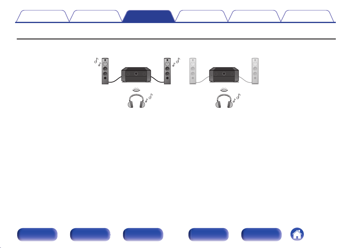
(Output Mode: Bluetooth + Speakers) (Output Mode: Bluetooth Only)
Contents Connections Playback Settings Tips Appendix
Listening to audio on Bluetooth headphones
You can listen to audio playing through the MAIN ZONE of this unit on Bluetooth headphones.
Output audio from connected speakers and Bluetooth headphones simultaneously, or only using Bluetooth headphones.
Front panel Display Rear panel Remote Index
97
Page 98
Contents
Connections Playback Settings Tips Appendix
Listening to audio on Bluetooth
headphones
Set “Transmitter” to “On” from the “General” -
1
“Bluetooth Transmitter” setting in the menu.
(v p. 254)
Select “Output Mode”, and set audio output method.
2
Audio is output to Bluetooth
Bluetooth + Speakers
(Default):
Bluetooth Only:
Enter pairing mode on the Bluetooth headphones you
3
want to connect to this unit.
Select “Device List” and select the name of the
4
Bluetooth headphones from the device list.
headphones and main zone speakers.
This simultaneous output is suitable for
family movie night and other group
activities.
Audio is output to Bluetooth
headphones only.
This is suitable for listening to music or
watching movies by yourself at night
when you need to keep quiet.
“Output Mode” can also be set from “Bluetooth Transmitter” in the option menu.
0
A2DP profile-compatible Bluetooth speakers can be connected following the same
0
steps used to connect Bluetooth headphones.
NOTE
Bluetooth headphone volume cannot be adjusted by the VOLUME knob on this
0
unit or the VOLUME buttons on the remote control unit. Adjust the volume using
the Bluetooth headphones.
If you are using Bluetooth headphones that do not have volume control, or if the
0
volume is insufficient, you can control the volume by adjusting the “Level” of the
“Bluetooth Transmitter” from the options menu. (v p. 99)
Stereo mode is fixed as the sound mode when using Bluetooth headphones. Any
0
sound modes and other audio settings are not reflected in audio output on
Bluetooth headphones.
Audio settings, sound modes and All Zone Stereo mode are not available while
using Bluetooth headphones and “Output Mode” is set to “Bluetooth Only”.
Audio may be delayed when sent over Bluetooth.
0
AirPlay audio cannot be transmitted.
0
Bluetooth headphones cannot be connected when use a Bluetooth input source in
0
any zone.
Furthermore, selecting a Bluetooth input source in any zone will terminate the
connection between this unit and Bluetooth headphones.
Bluetooth headphones cannot be connected when this unit is grouped in the
0
HEOS App.
Adjust the volume of connected Bluetooth headphones
5
after the connection is completed.
Front panel Display Rear panel Remote Index
98
Page 99
Contents Connections Playback Settings Tips Appendix
Adjusting the volume of Bluetooth
headphones
If you are using Bluetooth headphones that do not have volume control, or
if the volume is insufficient, you can control the volume by adjusting the
“Level” of the “Bluetooth Transmitter” from the options menu.
Press OPTION.
1
An option menu screen is displayed.
When the input source is “HEOS Music”, an option menu for
0
online music is displayed. Select “AVP Options…”, then press
ENTER.
Use cursor Up/Down to select “Bluetooth Transmitter”,
2
then press ENTER.
The “Bluetooth Transmitter” screen is displayed.
Use cursor Up/Down to select “Level”.
3
Use cursor Left/Right to adjust the volume, then press
4
ENTER.
–50 dB – +10 dB (Default: 0 dB)
This setting applies to all connected Bluetooth headphones, regardless of type.
0
Reconnecting to a Bluetooth
headphones
Follow any of the steps below to reconnect the most recently used
Bluetooth headphones:
Reconnect to this unit with Bluetooth headphone's reconnect function.
0
Go to “Bluetooth Transmitter” and then select “Reconnect” within the
0
options menu.
If “Output Mode” is set to “Bluetooth + Speakers”, this unit will
0
automatically connect to the most recently used Bluetooth headphones
when power is turned on.
Select the device you wish to connect from the “Device List” under
0
“Bluetooth Transmitter” in the menu. (v p. 254)
Front panel Display Rear panel Remote Index
99
Page 100
Contents Connections Playback Settings Tips Appendix
Disconnecting Bluetooth headphones
Complete any of the following steps to disconnect your Bluetooth
headphones:
Turn off your Bluetooth headphones.
0
Go to “Bluetooth Transmitter” and then select “Disconnect” within the
0
options menu.
In the setup menu, go to “General” - “Bluetooth Transmitter”, and set
0
“Transmitter” to Off. (v p. 254)
Front panel Display Rear panel Remote Index
100
 Loading...