

Page 1
GB
Operating instructions
Last updated: 01.2014
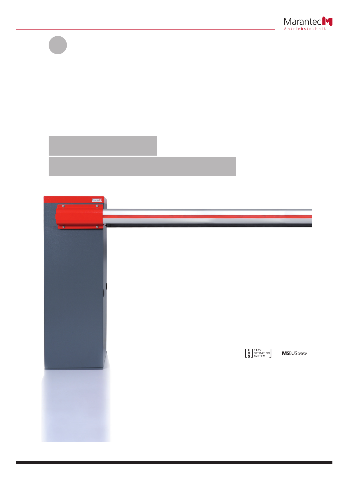
Parking barrier
Parc 200 / Parc 200 speed
Page 2
1. Meaning of symbols . . . . . . . . . . . . . . . . . . . . . . . . .2
2. Table of contents . . . . . . . . . . . . . . . . . . . . . . . . . . . .2
3. General safety advice . . . . . . . . . . . . . . . . . . . . . . . .3
4. Product overview . . . . . . . . . . . . . . . . . . . . . . . . . . . .4
4.1 Parc 200 supply package . . . . . . . . . . . . . . . . . .4
4.2 Dimensions . . . . . . . . . . . . . . . . . . . . . . . . . . . .5
4.3 Options . . . . . . . . . . . . . . . . . . . . . . . . . . . . . . .6
5. Preparation for mounting . . . . . . . . . . . . . . . . . . . . .6
5.1 General notes . . . . . . . . . . . . . . . . . . . . . . . . . .6
5.2 Checks . . . . . . . . . . . . . . . . . . . . . . . . . . . . . . . .7
5.3 Concrete foundation layout . . . . . . . . . . . . . . . .7
5.4 Cabling layout . . . . . . . . . . . . . . . . . . . . . . . . . .8
6. Installation . . . . . . . . . . . . . . . . . . . . . . . . . . . . . . . . .8
6.1 Mounting the parking barrier cabinet . . . . . . . .8
6.2 Mounting the parking barrier arm . . . . . . . . . . .9
6.3 Mounting the spring units . . . . . . . . . . . . . . . . .9
6.4 Setting the boom position . . . . . . . . . . . . . . . .10
6.5 Reversing the side of opening . . . . . . . . . . . . .11
6.6 Connection of control elements . . . . . . . . . . .12
7. Operation . . . . . . . . . . . . . . . . . . . . . . . . . . . . . . . . .12
7.1 Operating systems . . . . . . . . . . . . . . . . . . . . . .12
7.2 Release . . . . . . . . . . . . . . . . . . . . . . . . . . . . . .13
8. Attachment . . . . . . . . . . . . . . . . . . . . . . . . . . . . . . . .14
8.1 Technical Data for Parc 200 / Parc 200 speed . .14
8.2 Colour coding and assignment of
counterbalance spring . . . . . . . . . . . . . . . . . . .14
8.3 Maintenance . . . . . . . . . . . . . . . . . . . . . . . . . .15
8.4 Disassembly . . . . . . . . . . . . . . . . . . . . . . . . . . .15
8.5 Declaration of Incorporation /
Declaration of performance 2013-02 . . . . . . . .16
Caution!
Danger of personal injury!
The following safety advice must be observed at
all times so as to avoid personal injury!
Attention!
Danger of material damage!
The following safety advice must be observed at
all times so as to avoid material damage!
Advice / Tip
Check
Reference
i
Advice
Identification plate on parking barrier
Type: ____________________________________________________
Art. No.: _________________________________________________
Product No.: ______________________________________________
2. Table of contents1. Meaning of symbols
2 Installation and Operating Instructions, Parc 200, Parc 200 speed GB (#106313)
Page 3

3. General safety advice
Please read carefully!
IMPORTANT SAFETY INSTRUCTIONS:
IMPORTANT - PLEASE OBSERVE ALL SAFETY INSTRUCTIONS TO PREVENT
INJURY TO PERSONS.
PLEASE KEEP THESE INSTRUCTIONS FOR FURTHER USE.
IMPORTANT INSTRUCTIONS FOR SAFE INSTALLATION:
IMPORTANT - INCORRECT INSTALLATION CAN RESULT IN SERIOUS INJURY.
PLEASE FOLLOW ALL INSTALLATION INSTRUCTIONS.
Target group
This operator system may only be installed, connected and put into
operation by qualified and trained professionals!
Qualified and trained specialist personnel are persons
- who have knowledge of the general and special safety regulations,
- who have knowledge of the relevant electro-technical regulations,
- with training in the use and maintenance of suitable safety equipment,
- who are sufficiently trained and supervised by qualified electricians,
- who are able to recognise the particular hazards involved when working
with electricity,
- with knowledge regarding applications of the EN 12635 standard
(installation and usage requirements).
Warranty
For an operations and safety warranty, the advice in this instruction
manual has to be observed. Disregarding these warnings may lead
to personal injury or material damage. If this advice is disregarded,
the manufacturer will not be liable for damages that might occur.
The warranty does not include batteries, rechargeable batteries, fuses and
bulbs.
To avoid installation errors and damage to the parking barrier system, it is
essential that the installation instructions are followed. The system may
only be used after thoroughly reading the respective mounting and
installation instructions.
The installation and operating instructions must be submitted to the
parking barrier operator and kept in a safe place. They contain important
advice for operation, checks and maintenance.
This item is produced according to the directives and standards mentioned
in the Manufacturer's Declaration and in the Declaration of Conformity.
The product has left the factory in perfect condition with regard to safety.
Power-operated installations must be checked by an expert (and this must
be documented) before they are put into operation and thereafter as
required, but at least once a year.
Correct use
The parking barrier system is designed exclusively for use in access zones.
Its purpose is to provide safe access for goods and vehicles, whether
guided or driven by persons, in industrial parks or residential areas.
Please note that this operator system must only be used with the barrier
arms and counterbalance springs supplied by the manufacturer.
Information on installing the parking barrier system
• Render any installations inoperable that will no longer be needed after
the parking barrier system has been installed.
• Before commencing cabling works it is very important to disconnect the
operator system from the electricity supply.
Ensure that the electricity supply remains disconnected throughout the
cabling works.
• Adhere to the local protection regulations.
• Use only fixing materials which are approved for the substrate
concerned.
• Lay the electricity supply cables and control cables; these MUST be laid
separately. The controls voltage is 24 V DC.
• Mount all pulse generators and control devices (e.g. radio code keypad)
within sight of the parking barrier and at a safe distance from any
moving parts of the parking barrier system.
Advice on commissioning the park barrier system
To ensure proper operation of the system within the CEN (European
Committee for Standardisation) states it is essential that the relevant
European health and safety directives and standards are taken into
account. The technical data relating to environmental conditions,
degree of protection, loading and duty cycle must be complied with.
All parking barrier users must be instructed in the system’s operation
once it has been installed.
• Make sure that children cannot play with the controls.
• Make sure before operating the parking barrier that no objects or
people are in the danger zone of the parking barrier.
• Test all existing emergency command devices.
• Never place your hands in a moving parking barrier or moving parts.
• Be aware of possible crushing and shearing hazards posed by the
parking barrier system.
The EN 13241-1 regulations must be observed.
Advice on servicing the parking barrier system
To ensure proper operation, the following items must be checked regularly
and repaired if necessary. Before any works to the parking barrier system
are undertaken, the operator system must be disconnected from the
mains.
• Check once a month to ensure that the operator system reverses if the
parking barrier encounters an obstacle. Depending on the operational
direction of the parking barrier, place a 1,500 mm high obstacle in its
path.
• Perform a check on the OPEN and CLOSE automatic cut-out setting.
• Check all movable parts of the parking barrier system.
• Check the parking barrier system for wear or damage.
• Inspect the safety devices installed every six months.
Information on cleaning the parking barrier system
Never use water jets, high pressure cleaners, acids or bases for cleaning.
Beside the advice in these instructions, please observe the general
safety and accident prevention regulations!
Our sales and supply terms and conditions are effective.
Installation and Operating Instructions, Parc 200, Parc 200 speed GB (#106313) 3
Page 4
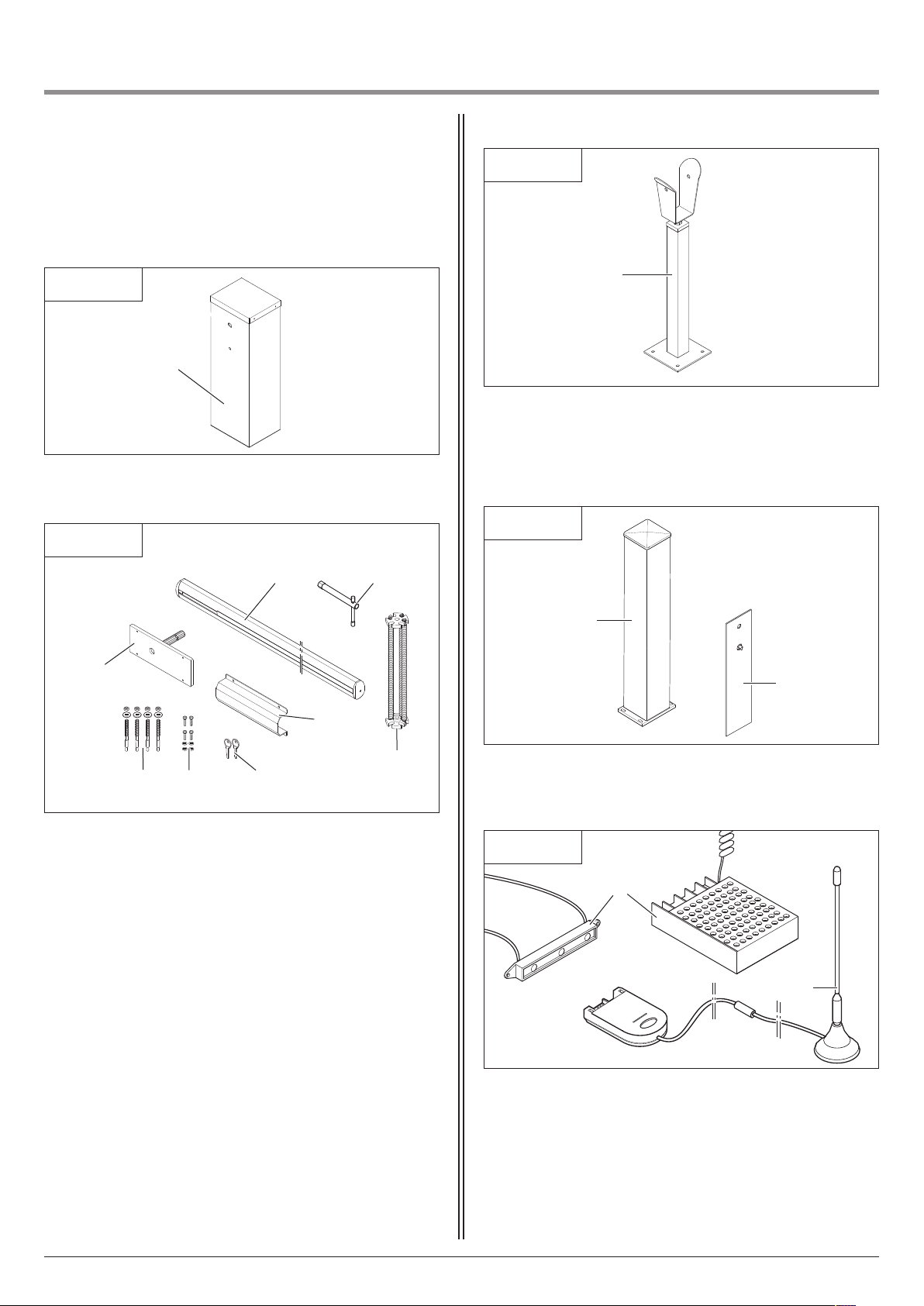
4.1 Parc 200 supply package
1 Parc 200 cabinet
Standard package
4.1 / 1
1
4 Installation and Operating Instructions, Parc 200, Parc 200 speed GB (#106313)
4. Product overview
2 Barrier arm (boom) (3 m, 4 m)
3 Release key
4 Spring unit
5 Counter bracket
6 Key (2x)
7 Screw set
8 Heavy-duty dowel M10
9 Full-floating axle
10 Boom end support post with cradle section, height-
adjustable (optional where barrier arm is less than 4 m
long, essential where barrier arm is 4 metres or more in
length)
4.1 / 3
!¯
4.1 / 4
Accessories
11 Support post, empty housing
12 Manual release mechanism
4.1 / 5
13 Magnetic base aerial (Digital 178)
14 Barrier arm (boom) LED light
!@
!”
!#
!£
2
9
3
4.1 / 2
5
6
4
7
8
Page 5
4. Product overview
Installation and Operating Instructions, Parc 200, Parc 200 speed GB (#106313) 5
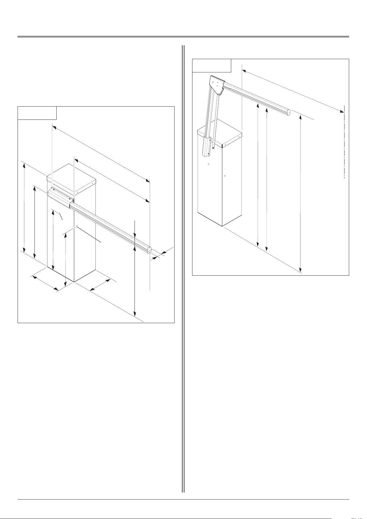
4.2 / 1
Parc 200
A Barrier arm (boom) length
B Span = barrier arm length -300
C Coiled cable ducting
D Photocell barrier adapter
D
C
4.2 Dimensions
4.2 / 2
Parc 200 park barrier with articulated arm
E Clearance height with 2000 mm rubber profile
F Clearance height without 2030 mm rubber profile
G Access width 2000 mm
H Required height 2150 mm
1200
995
G
A
B
80
E
F
H
800
500
400
320
955
40
Page 6
4. Product overview
6 Installation and Operating Instructions, Parc 200, Parc 200 speed GB (#106313)
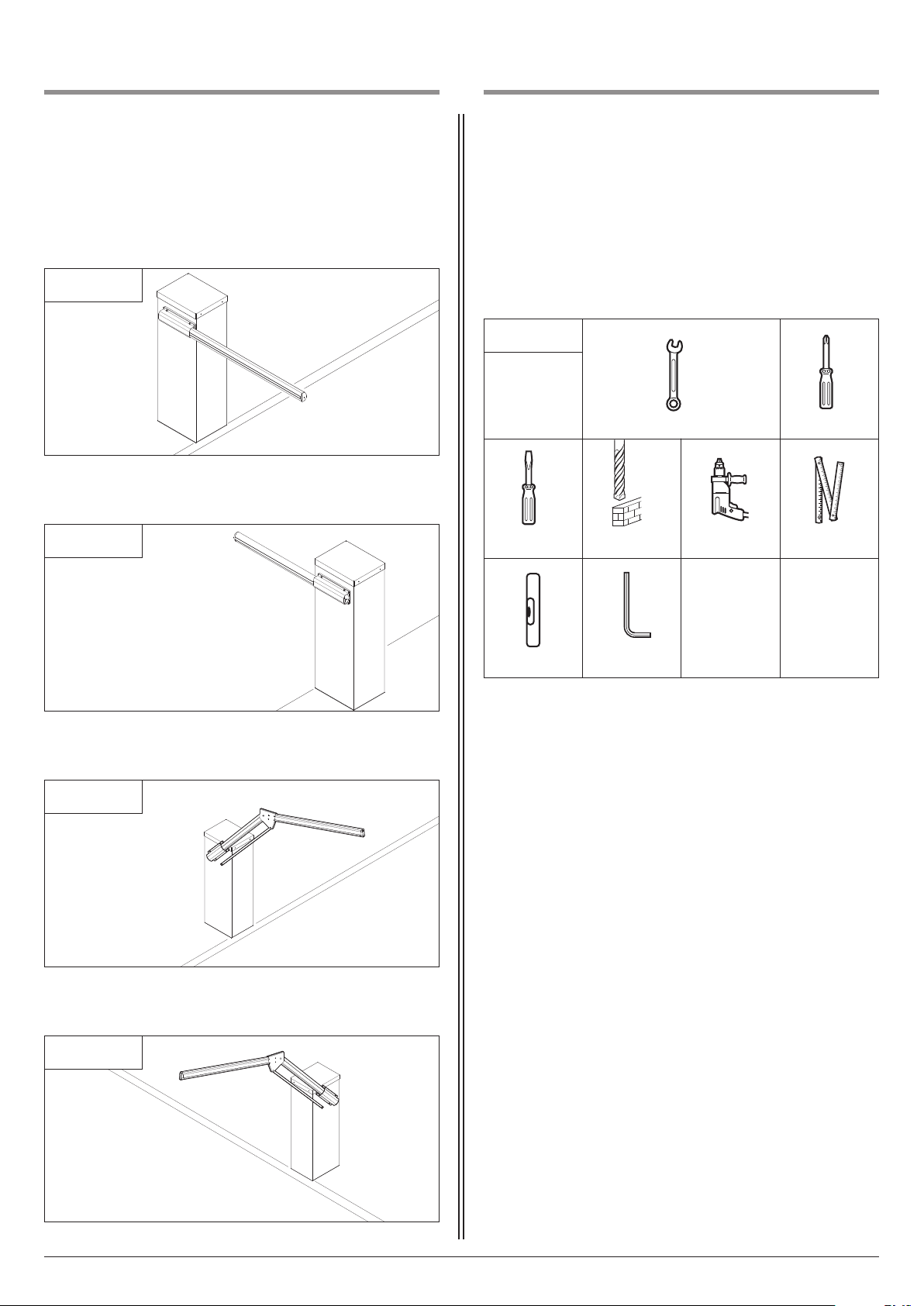
4.3 / 1
Parking barrier cabinet on the left
4.3 / 2
Parking barrier cabinet on the right
4.3 / 3
Parking barrier cabinet on the left with articulated arm
4.3 / 4
Parking barrier cabinet on the right with articulated arm
5.1 General notes
The pictures in these instructions are not true-to-scale.
Dimensions are always given in millimetres (mm)!
For correct mounting you will need the following tools:
5.1 / 1
10 / 13 / 17 / 19 / 22 / 24 2
3 ø 10
3 / 5 / 6
5. Preparation for mounting
4.3 Options
Transport
The barrier arm housing must
- be transported upright and
- be prevented from falling over.
Page 7
5. Preparation for mounting
Installation and Operating Instructions, Parc 200, Parc 200 speed GB (#106313) 7
Attention!
In order to guarantee correct mounting, carry
out the following checks before installing.
Supply package
• Check the package to ensure that all the parts are included.
• Check that you have all the additional components that are
necessary for your particular installation requirements.
Parking barrier system
• Ensure that a suitable mains connection and a mains disconnection facility are available for your parking barrier system. The
minimum cross-sectional area of the earth cable is 3 x 1.5 mm
2
.
• Ensure that all cables are suitable for outdoor use (UV resistant
and cold resistant).
Attention!
To prevent damage to the concrete foundation,
the size of the foundation base must comply
with the instructions.
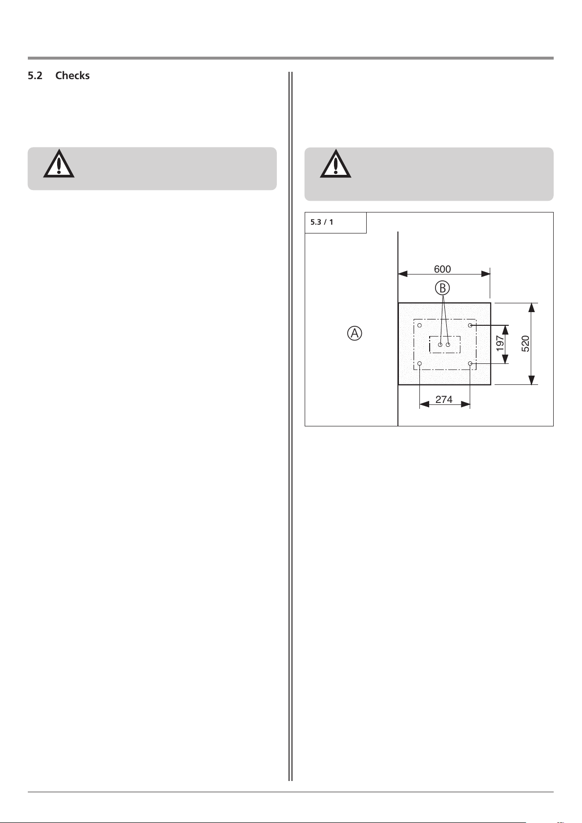
A Driveway
B Duct pipe for cabling to control panel and mains supply
cabling
The depth of the concrete base must be at least 800 mm.
5.3 Concrete foundation layout
600
520
197
274
5.3 / 1
A
B
5.2 Checks
Page 8
5. Preparation for mounting
Attention!
A concrete foundation according to the
specifications must be provided and be
hardened to ensure satisfactory long-term
operation of the parking barrier system.
6.1 Mounting the parking barrier cabinet
6. Installation
• Open the cabinet.
6.1 / 1
6.1 / 2
• Screw the cabinet to the concrete base.
6.1 / 3
• Insert aerial through the cable ducting (optional).
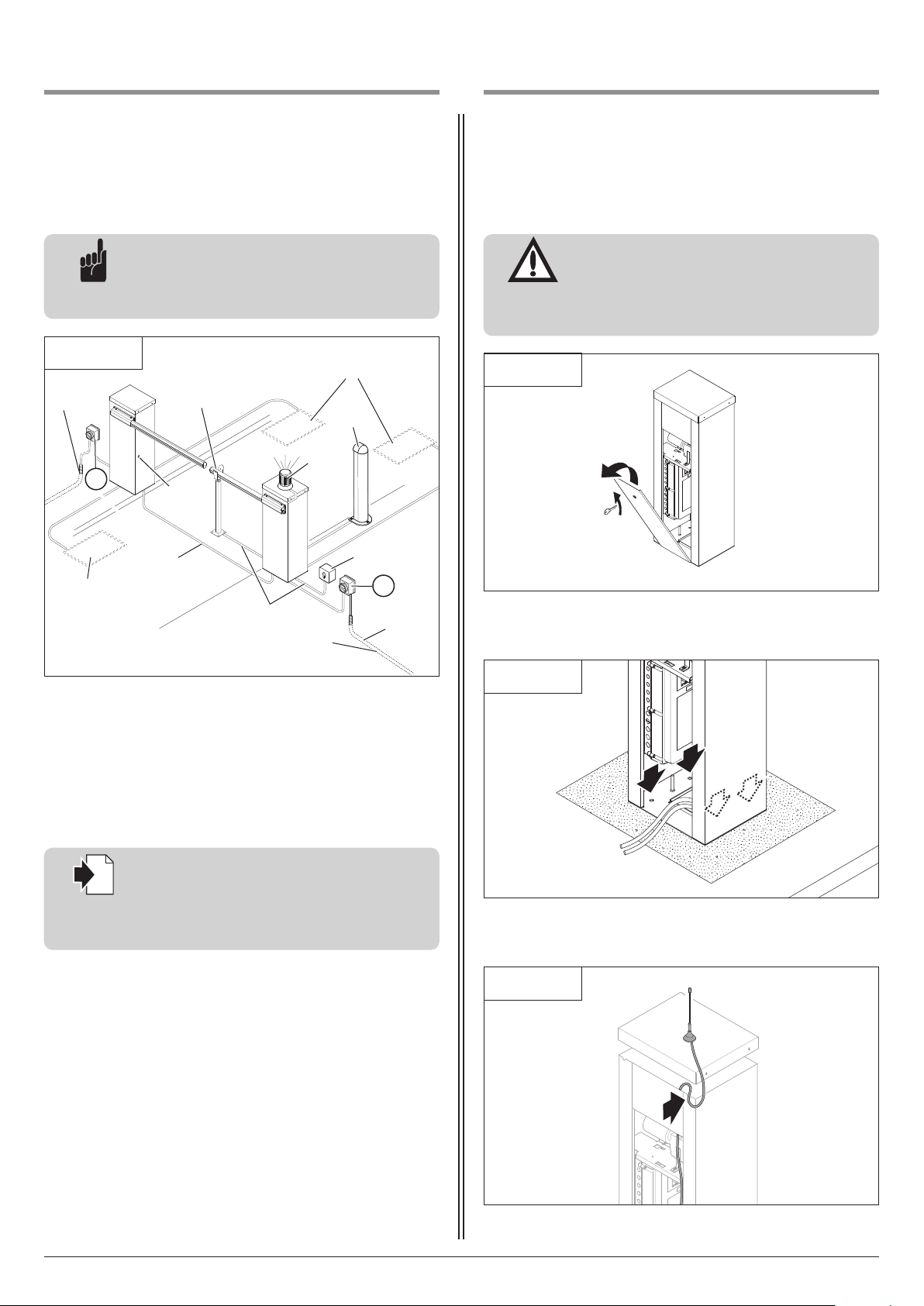
5.4 Cabling layout
Advice:
This is just an example of a cabling layout; the
layout can vary depending on the associated
equipment.
Reference:
For the installation and cabling of the sensors,
control elements and safety equipment, the
relevant installation instructions must be
observed.
i
1 Photocell
2 Signal light
3 Code button, transponder, Coin acceptor
4 Key switch
5 Mains isolator switch (mains disconnection facility)
6 Mains supply cable
7 Induction loops
8 Magnetic lock
8 Installation and Operating Instructions, Parc 200, Parc 200 speed GB (#106313)
5.4 / 1
5
5
3 x 1,5 mm
2
230 V / AC
3 x 1,5 mm
2
230 V / AC
2 x 0,5 mm
2
2 x 0,8 mm
2
1
2
3
4
6
7
7
8
Page 9
6. Installation
Reference:
The procedure for releasing the operator is
described in Section 7.2.
i
• Release the operator.
• Raise the barrier arm until it is in an upright position.
• Lock the operator.
Caution!
- To prevent the unlocked barrier arm from
falling, the barrier arm must be locked when
it is in an upright position.
- To ensure correct operation, nuts (C) must be
locked after adjusting the tension of the
spring.
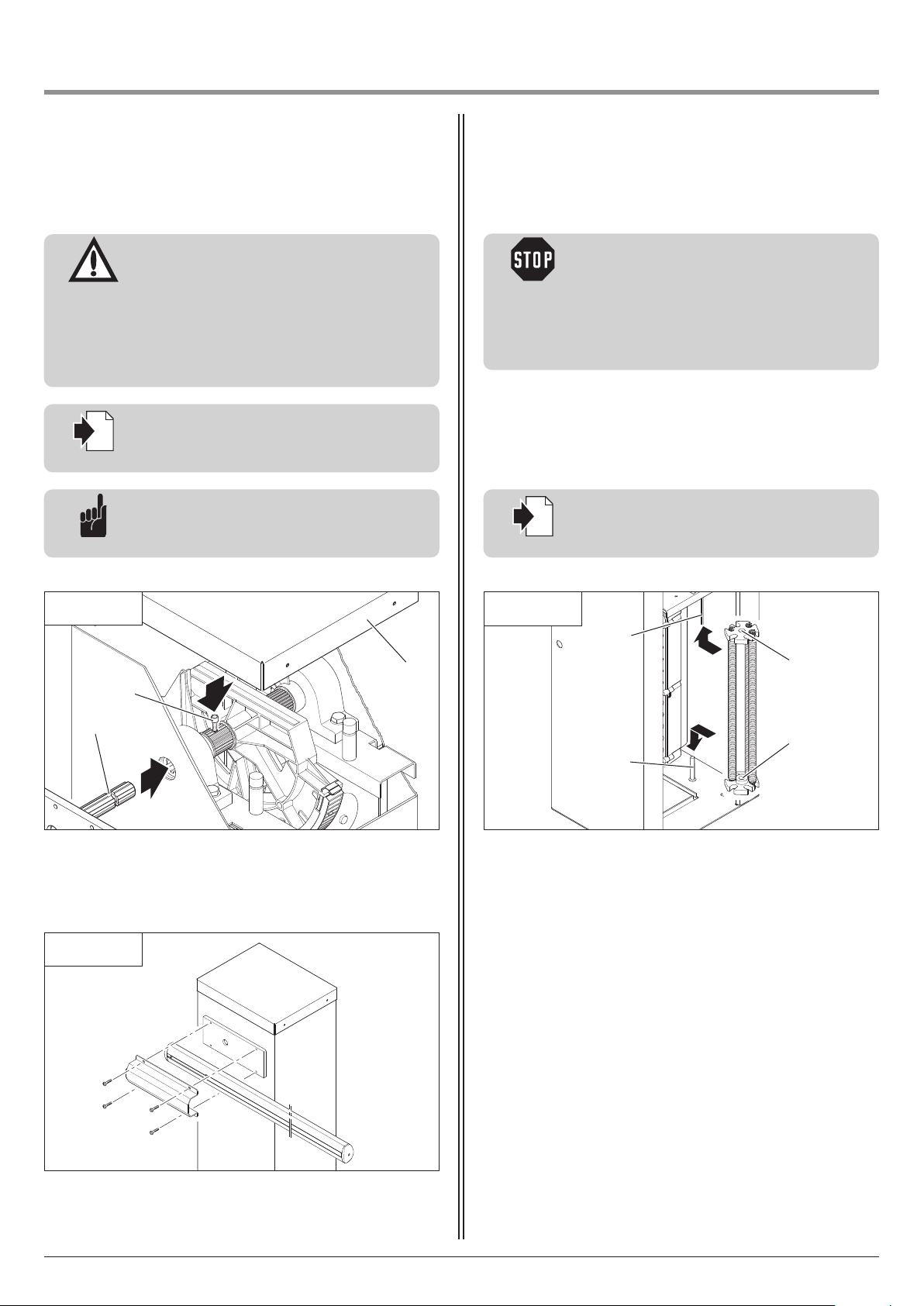
6.3 Mounting the spring units6.2 Mounting the parking barrier arm
Advice:
The shaft must be inserted so that the locking
screw (A) engages with groove (B).
Reference:
The procedure for reversing the side of opening
is described in Section 6.5.
i
Attention!
- To avoid damaging the barrier arm, the barrier
arm must be fitted by two people. The barrier
arm must be supported to prevent it from
falling before it is securely fixed in place.
- If the side on which the barrier arm opens
needs to be changed over, this must be
carried out before the barrier arm is fitted.
6.2 / 2
• Screw the barrier arm on in a horizontal position.
6.2 / 1
• Remove the cover (C).
• Fix the barrier arm adapter.
A
B
C
6.3 / 1
B
B
A
A
• Push the drill-holes (A) onto the threaded rods (B).
• Screw on the spring unit.
• Release the operator.
Installation and Operating Instructions, Parc 200, Parc 200 speed GB (#106313) 9
Page 10
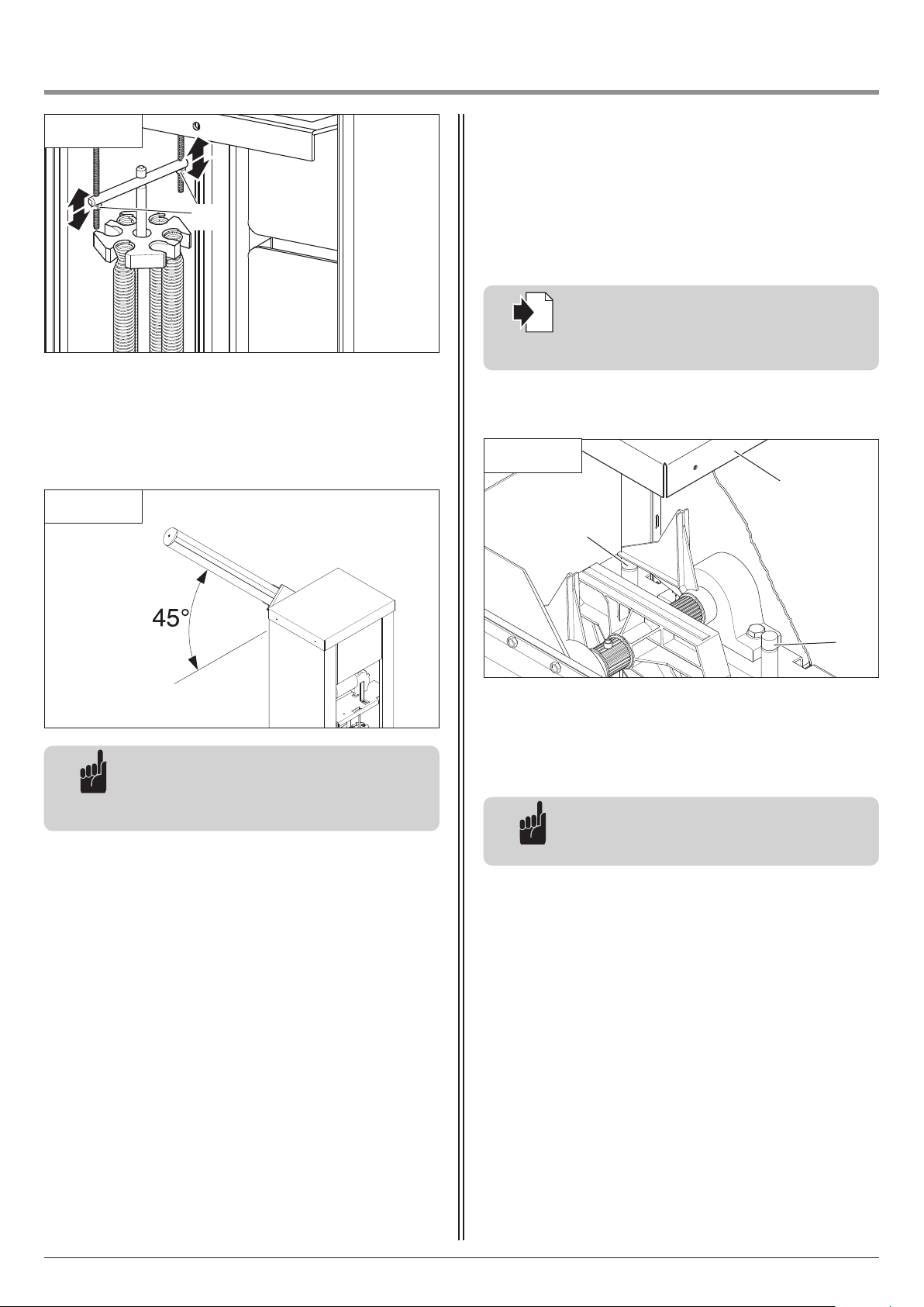
6. Installation
To set the barrier arm position
The barrier arm must be lowered and in a horizontal position.
6.4 / 1
• Remove the cover (A).
• Adjust the spring buffers (B) in pairs.
• Tighten the spring buffers (B).
B
B
A
To set the spring buffers
Reference:
The instructions for setting the OPEN and
CLOSED barrier arm positions can be found in
the control unit documentation.
i
Advice:
The tension of the spring must be adjusted so
that the barrier arm is automatically held in
place when it is in a half-opened position.
Advice:
The spring buffers (B) must be set so that they
are under slight tension.
6.4 Setting the boom position
6.3 / 2
• Set the tension of the spring.
• Lock the nuts (C).
• Lock the operator.
C
6.3 / 3
10 Installation and Operating Instructions, Parc 200, Parc 200 speed GB (#106313)
Page 11
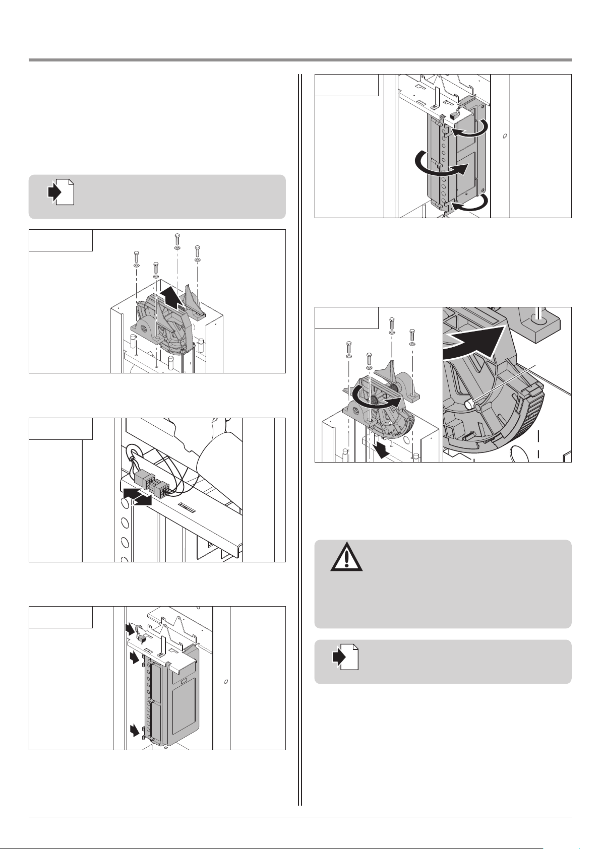
6. Installation
Attention!
After changing the opening side, the rotational
direction must be altered accordingly in order
to prevent damage to property.
To change the rotational direction, swap the
leads at terminals 1 and 2 of the motor
connection XM70A.
Reference:
The motor connection XM70A is described in
the control unit documentation.
i
• Take out barrier arm shoulder.
6.5 Reversing the side of opening
6.5 / 1
• Remove plug from socket.
6.5 / 2
Reference:
The procedure for releasing the operator is
described in Section 7.2.
i
• Release the operator.
• Remove controls from cabinet.
• Remove cable from cabinet.
6.5 / 3
6.5 / 4
• Lock the operator.
• Give controls a 180° turn.
• Screw hinges onto opposite side.
• Attach controls to cabinet.
• Screw reference point magnet (A) onto opposite side.
• Give barrier arm shoulder a 180° turn and replace in the
cabinet.
Installation and Operating Instructions, Parc 200, Parc 200 speed GB (#106313) 11
6.5 / 5
A
Page 12

6. Installation
12 Installation and Operating Instructions, Parc 200, Parc 200 speed GB (#106313)
Reference:
A description of the control unit can be found
in the relevant documentation for the control
unit.
i
7.1 Operating systems
The following operating devices can be used to actuate the
parking barrier system:
- Code keypad
- Transponder
- Coin acceptor
- Induction loop
- Hand transmitter / radio technology
Reference:
Please refer to the relevant manuals for
instructions on using the operating devices.
i
7. Operation
6.6 Connection of control elements
Page 13
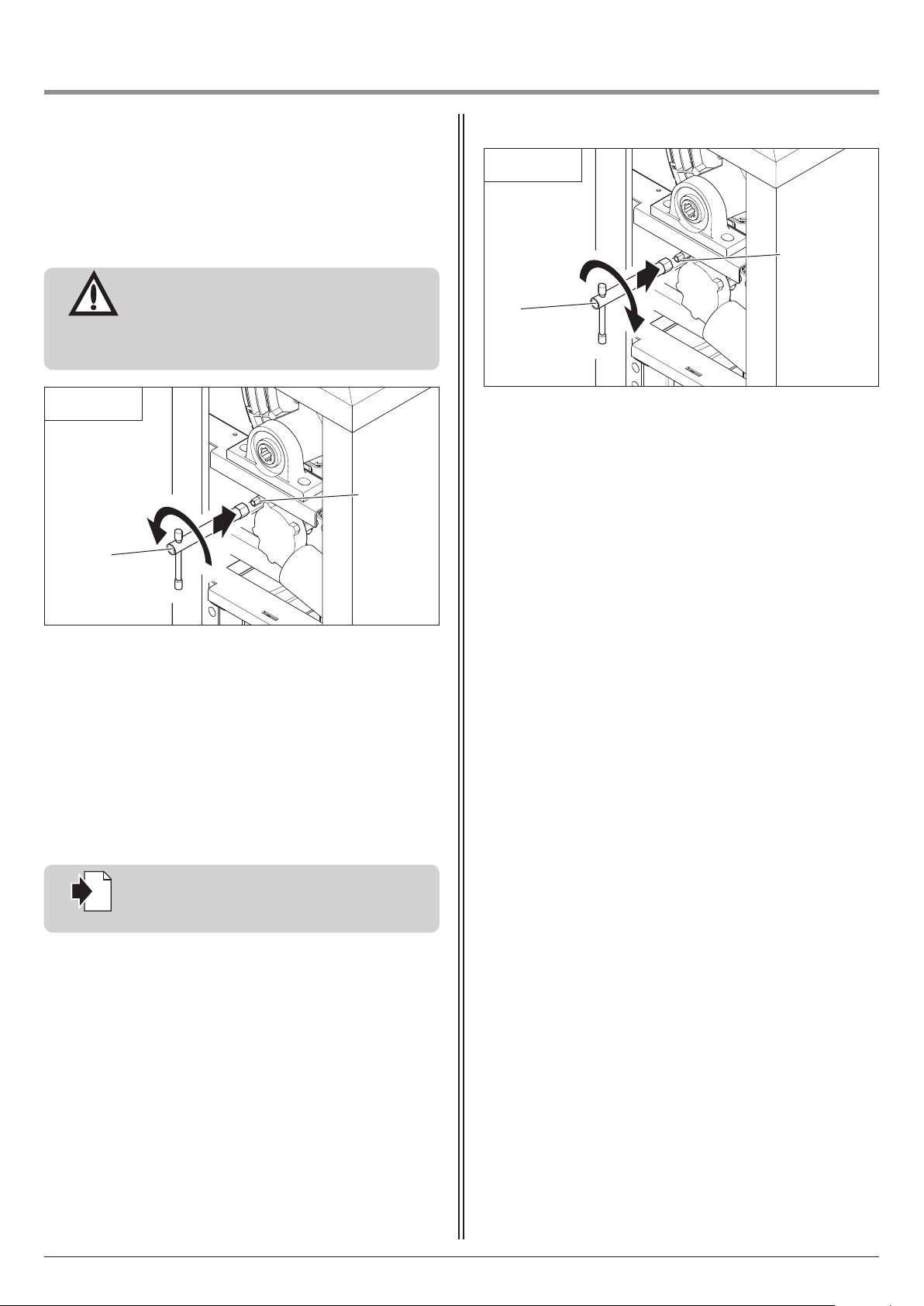
Installation and Operating Instructions, Parc 200, Parc 200 speed GB (#106313) 13
Attention!
To prevent damage, the barrier arm must only
be released if the spring unit is fully intact.
The barrier arm may move upwards during this
procedure.
7.2 / 1
Releasing
Locking
7.2 / 2
Reference:
The messages are explained in the
documentation supplied with the control unit.
i
7.2 Release
A
A
B
• Place release key (A) over red release nut (B).
• Turn release key (A) approx. 180° in an anticlockwise direction
until it stops.
• Partially raise and lower barrier arm manually.
The transmission is now mechanically disengaged from the drive
shaft. The parking barrier can only be moved manually.
The electric circuit in the controls is interrupted and the controls
are out of operation.
A corresponding message is displayed.
• Place release key (A) over red release nut (B).
• Turn release key (A) approx. 180° in a clockwise direction until
it stops.
• Partially raise and lower barrier arm manually.
The transmission and drive shaft are now mechanically engaged.
The parking barrier can only be moved with the motor.
The electric circuit in the controls is closed again and the controls
are in operation.
B
7. Operation
Page 14
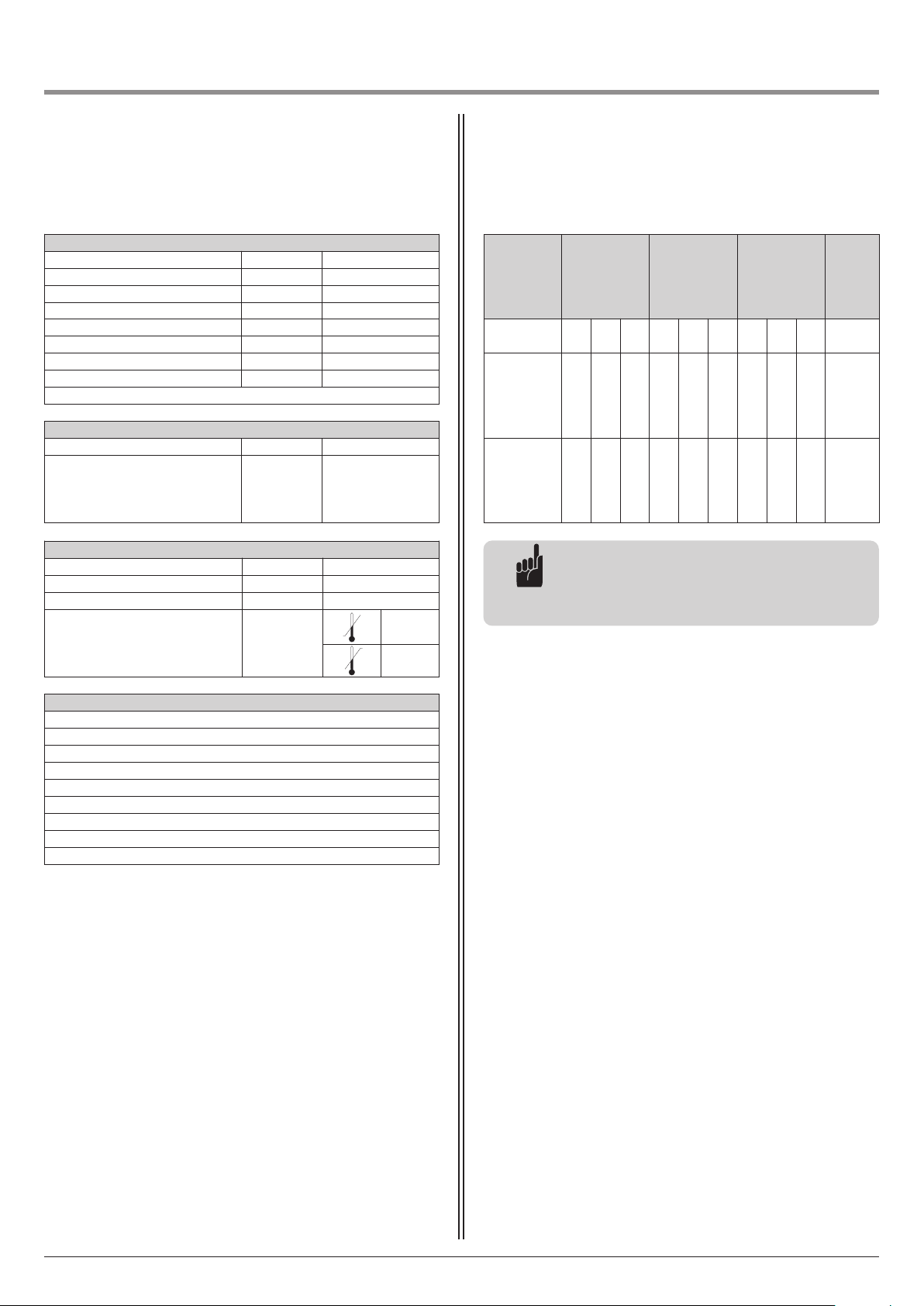
14 Installation and Operating Instructions, Parc 200, Parc 200 speed GB (#106313)
Electrical data
Nominal voltage *) V 230 / 260
Nominal frequency Hz 50 / 60
Power consumption A 1.1
Power input - operation KW 0,25
Power input - stand-by W 3.6
Operating mode (operating time) ED 90%
Control voltage V DC 24
Protection category, motor unit IP 65
*) subject to country-specific alternations
Mechanical data
Opening time (barrier specific) sec. 3 - 10
Movement cycles per day
Barrier arm length: up to 2.3 m
Barrier arm length: up to 3.3 m
Barrier arm length: up to 4.3 m
1,500
1,000
750
Features / Safety functions
Reference point technology x
Soft-Start / Soft-Stop x
Automatic cut-out x
Blocking protection x
Undervoltage protection x
Excess travel stop x
Electronic travel cut-out x
Connection for pushbuttons, code buttons and key switches x
Error messages x
8.2 Colour coding and assignment of
counterbalance spring
8.1 Technical Data for Parc 200 / Parc 200 speed
8. Attachment
Advice:
Barrier arms of 4 metres and more in length
also require an end support post with a cradle
section.
General data
Motor unit dimensions mm 405x325x1210
Weight kg 55
Sound pressure level db (A) < 70
Temperature range °C
-20
+60
Type of
barrier
Barrier arm
Barrier arm
with impact
protection
Barrier arm
with 8.2 kΩ
switching
strip
Articulated
arm
Barrier length
in metres
2,3 3,3 4,3 2,3 3,3 4,3 2,3 3,3 4,3 2
Counter balan
ce spring, red
#91386
(number)
3 0 2 1 2 1 1 2 1 3
Counter -
balance
spring, white
#91385
(number)
0 2 3 1 2 4 1 2 4 0
Page 15
Installation and Operating Instructions, Parc 200, Parc 200 speed GB (#106313) 15
8. Attachment
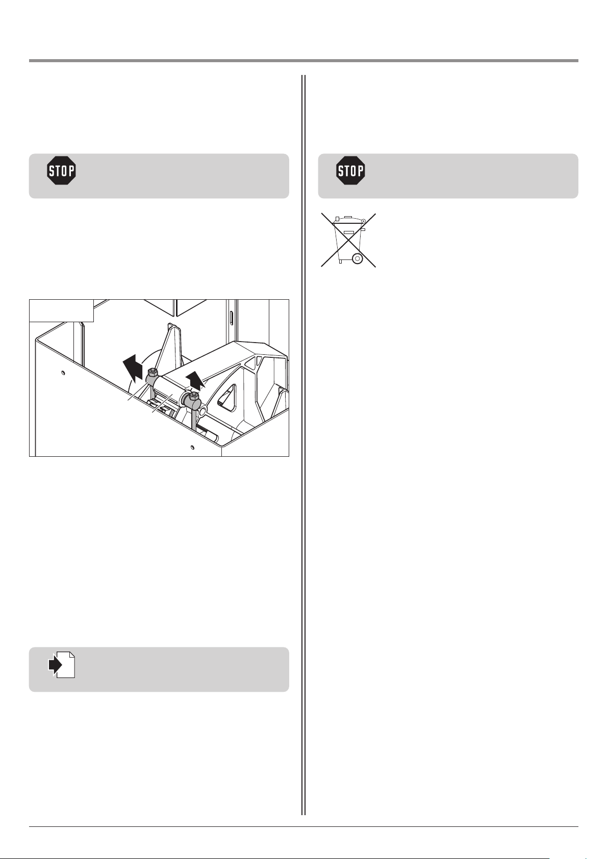
To ensure trouble-free operation, every 100,000 cycles:
- the springs must be replaced,
- the spring holder in the shoulder wheel must be cleaned and
lubricated with grease.
Caution!
To avoid injuries, the barrier arm must be
secured against falling.
• Open the door.
• Remove the cover.
• Release the operator.
• Open the barrier arm.
• Take all the springs out of the spring holder (A).
• Remove the spring holder (A) from the shoulder wheel (B).
• Clean and grease the spring holder (A).
• Assemble all the components again in the reverse order.
Lubricating the spring holder
Reference:
The procedure for releasing the operator is
described in Section 7.2.
i
10.3 / 1
A
B
To disassemble, follow assembly instructions in
reverse order.
8.4 Disassembly
Caution!
To avoid injuries, the barrier arm must be
secured against falling.
8.3 Maintenance
Page 16
16 Installation and Operating Instructions, Parc 200, Parc 200 speed GB (#106313)
8. Attachment
8.5 Declaration of Incorporation /
Declaration of performance 2013-02
We hereby declare that in its design and construction, and in the
form as delivered, the product mentioned below complies with
the relevant basic requirements of the EC Machinery Directive
(2006/42/EC).
This declaration shall no longer be valid if changes are made to
the product without our authorisation.
Product: Parking barrier system Parc 200, Parc 200 speed
Revisionsstand: R01
In addition, the machinery is in conformity with all regulations of
the EU Construction Products Regulation No. 305/2011, the
Electromagnetic Compatibility Directive 2004/108/EC and the
Low Voltage Directive 2006/95/EC.
– Machinery Directive 2006/42/EC
Health and safety requirements applied according to Annex 1
EN 60204-1:2007
EN ISO 12100:2011
EN ISO 13849-1:2008
Cat. 2 / PLC for the functions of power limitation and end
position detection
– EMC electromagnetic compatibility 2004/108/EC
EN 55014-1:2012
EN 61000-3-2:2010
EN 61000-3-3:2009
EN 61000-6-2:2006
EN 61000-6-3:2011
– Low voltage directive 2006/95/EC
EN 60335-1:2012
EN 60335-2-103:2010
The relevant technical documentation is compiled in accordance
with Annex VII(B) of the Machinery Directive 2006/42/EC. We
undertake to transmit, in response to a reasoned request by the
market surveillance authorities, this information in electronic form
within a reasonable term.
Intended use
This barrier system is manufactured for installation in access and
entry areas in commercial or private facilities, in compliance with
the harmonised standards DIN EN 13241-1:2003.
Type tested by TÜV Nord Cert GmbH - 0044
Assessment of constancy of performance according to system 3
Declared performance:
Resistance to wind load Class 1
Operating forces / closing forces Pass
Safe opening Pass
01.09.2013 M. Hörmann
Management
Person authorised to compile the relevant technical
documentation:
Marantec Antriebs- und Steuerungstechnik
GmbH & Co. KG
Remser Brook 11 · 33428 Marienfeld · Germany
Phone: +49 5247 705-0
Page 17

Installation and Operating Instructions, Parc 200, Parc 200 speed GB (#106313) 17
Page 18

18 Installation and Operating Instructions, Parc 200, Parc 200 speed GB (#106313)
Page 19

Installation and Operating Instructions, Parc 200, Parc 200 speed GB (#106313) 19
Page 20

English Original operating instructions protected by copyright.
No part of this manual may be reproduced without our prior consent.
Subject to changes which are in the interest of technical improvements.
106313
1 - GB 360407 - M - 0.5 - 0114
 Loading...