

Page 1

Dynamic 736, 741 FU
ntriebssystem für Schiebetore
A
Operator system for Sliding Gates
D
GB
Montage- und Bedienungsanleitung
Manual for installation and operation
Page 2
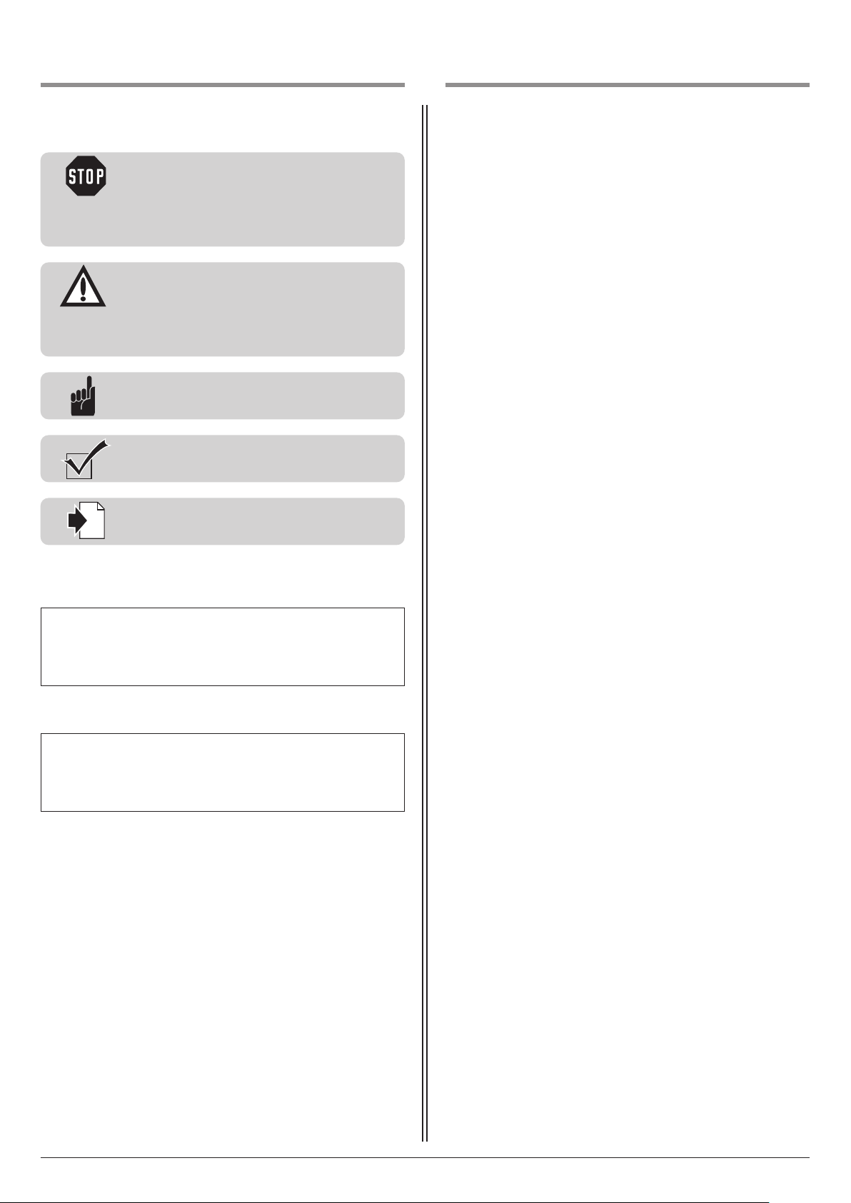
1. Symbolerklärung
i
2. Inhaltsverzeichnis
Hinweise
Vorsicht!
Gefahr von Personenschäden!
Hier folgen wichtige Sicherheits hinweise, die zur
ermeidung von Personen schäden unbedingt
V
beachtet werden müssen!
Achtung!
Gefahr von Sachschäden!
Hier folgen wichtige Sicherheitshinweise, die zur
Vermeidung von Sachschäden unbedingt
beachtet werden müssen!
Hinweis / Tipp
Kontrolle
Verweis
1. Symbolerklärung . . . . . . . . . . . . . . . . . . . . . . . . . . . .2
2. Inhaltsverzeichnis . . . . . . . . . . . . . . . . . . . . . . . . . . . .2
3. Allgemeine Sicherheitshinweise . . . . . . . . . . . . . . . .3
4. Produktübersicht . . . . . . . . . . . . . . . . . . . . . . . . . . . .5
4.1 Lieferumfang Dynamic 736, 741 FU . . . . . . . . . .5
.2 Abmessungen . . . . . . . . . . . . . . . . . . . . . . . . . .5
4
4.3 Torvarianten . . . . . . . . . . . . . . . . . . . . . . . . . . . .6
5. Montagevorbereitungen . . . . . . . . . . . . . . . . . . . . . .6
5.1 Allgemeine Angaben . . . . . . . . . . . . . . . . . . . . .6
5.2 Kontrollen . . . . . . . . . . . . . . . . . . . . . . . . . . . . .7
5.3 Tor- und Fundamentplan . . . . . . . . . . . . . . . . . .7
.4 Verkabelungsplan . . . . . . . . . . . . . . . . . . . . . . .8
5
6. Montage . . . . . . . . . . . . . . . . . . . . . . . . . . . . . . . . . . .8
6.1 Montage des Motor-Aggregats . . . . . . . . . . . . .8
6.2 Montage der Zahnstange . . . . . . . . . . . . . . . . .10
6.3 Höhenanpassung des Motor-Aggregats . . . . . .12
6.4 Entriegelung . . . . . . . . . . . . . . . . . . . . . . . . . .12
6.5 Steuerungsanschlüsse . . . . . . . . . . . . . . . . . . .13
7. Inbetriebnahme . . . . . . . . . . . . . . . . . . . . . . . . . . . .13
8. Anhang . . . . . . . . . . . . . . . . . . . . . . . . . . . . . . . . . . .14
8.1 Technische Daten Dynamic 736, 741 FU . . . . .14
8.2 Erklärung für den Einbau einer unvollständigen
Maschine . . . . . . . . . . . . . . . . . . . . . . . . . . . . .15
Typenschild Steuerung
Typ: _____________________________________________________
Art.-Nr.: __________________________________________________
Produkt-Nr.: ______________________________________________
Typenschild Motor-Aggregat
Typ: _____________________________________________________
Art.-Nr.: __________________________________________________
Produkt-Nr.: ______________________________________________
2 Montage- und Bedienungsanleitung, Dynamic 736, 741 FU D (#116119)
Page 3

3. Allgemeine Sicherheitshinweise
Bitte unbedingt lesen!
Zielgruppe
– Montage, Anschluss, Inbetriebnahme und Wartung:
qualifiziertes, geschultes Fachpersonal.
– Bedienung, Prüfung und Wartung:
Betreiber der Toranlage.
Anforderungen an qualifiziertes und geschultes Fachpersonal:
– Kenntnis der allgemeinen und speziellen Sicherheits- und Unfall -
verhütungsvorschriften.
– Kenntnis der einschlägigen elektrotechnischen Vorschriften.
– Ausbildung in Gebrauch und Pflege angemessener Sicherheits -
ausrüstung.
– Ausreichende Unterweisung und Beaufsichtigung durch
Elektrofachkräfte.
– Fähigkeit, Gefahren zu erkennen, die durch Elektrizität verursacht wer-
den können.
– Kenntnis in der Anwendung folgender Normen
– EN 12635 („Tore - Einbau und Nutzung“),
– EN 12453 („Tore - Nutzungssicherheit kraftbetätigter Tore –
Anforderungen“),
– – EN 12445 („Tore - Nutzungssicherheit kraftbetätigter Tore –
Prüfverfahren“),
– – EN 13241-1 („Tore - Produktnorm - Teil 1:
Produkte ohne Feuer- und Rauchschutzeigenschaften“).
Anforderungen an Betreiber der Toranlage:
– Kenntnis und Aufbewahrung der Betriebsanleitung.
– Aufbewahrung des Prüfbuches.
– Kenntnis der allgemeinen Sicherheits- und Unfall verhütungsvorschriften.
– Einweisung aller Personen, die die Toranlage benutzen.
– Sicherstellen, dass die Toranlage regelmäßig nach Herstellerangaben von
qualifiziertem, geschultem Fachpersonal geprüft und gewartet wird.
Für folgende Benutzer gelten besondere Anforderungen:
– Kindern ab 8 Jahren und darüber.
– Personen mit verringerten physischen, sensorischen oder mentalen
Fähigkeiten.
– Personen mit Mangel an Erfahrung und Wissen.
Diese Benutzer dürfen nur tätig werden bei der Bedienung des Geräts.
Besondere Anforderungen:
– Benutzer werden beaufsichtigt.
– Benutzer wurden bezüglich des sicheren Gebrauchs des Geräts unter-
wiesen.
– Benutzer verstehen Gefahren im Umgang mit dem Gerät.
– Kinder dürfen nicht mit dem Gerät spielen.
Gewährleistung
Für eine Gewährleistung in Bezug auf Funktion und Sicherheit müssen die
Hinweise in dieser Anleitung beachtet werden. Bei Missachtung der
Warnhinweise können Körperverletzungen und Sachschäden auftreten.
Für Schäden, die durch Nichtbeachtung der Hinweise eintreten, haftet der
Hersteller nicht.
Von der Gewährleistung ausgeschlossen sind Batterien, Sicherungen und
Glühlampen.
Um Einbaufehler und Schäden an Tor und Antriebssystem zu ver meiden,
ist unbedingt nach den Montage an weisungen der Einbau anleitung vorzugehen. Das Produkt darf erst nach Kenntnisnahme der zugehörigen
Einbau- und Bedienungs anleitung betrieben werden.
Die Einbau- und Bedienungsanleitung ist dem Betreiber der Toranlage zu
übergeben und aufzubewahren. Sie beinhaltet wichtige Hinweise für
Bedienung, Prüfung und Wartung.
Das Produkt wird gemäß den in der Hersteller- und Konformitäts erklärung
aufgeführten Richtlinien und Normen gefertigt. Das Produkt hat das Werk
in sicherheitstechnisch einwandfreiem Zustand verlassen.
Kraftbetätigte Fenster, Türen und Tore müssen vor der ersten Inbetrieb nahme und nach Bedarf, jedoch jährlich mindestens einmal von einem
Sachkundigen geprüft werden (mit schriftlichem Nachweis).
Bestimmungsgemäße Verwendung
Das Antriebssystem ist ausschließlich für das Öffnen und Schließen von
Schiebetoren bestimmt.
Toranforderungen
Das Antriebssystem Dynamic 736 ist geeignet für:
- Schiebetore bis zu einer Tormasse von 1.100 kg.
Das Antriebssystem Dynamic 741 FU ist geeignet für:
- Schiebetore bis zu einer Tormasse von 1.300 kg.
Das Tor muss:
- mechanische Endanschläge in beiden Richtungen haben,
- einen geraden Laufweg haben, d.h. keinesfalls mit Gefälle.
Neben den Hinweisen in dieser Anleitung sind die allgemein
gültigen Sicherheits- und Unfall vorschriften zu beachten!
Es gelten unsere Verkaufs- und Lieferbedingungen.
Hinweise zum Einbau des Antriebssystems
• Stellen Sie sicher, dass sich das Tor mechanisch in einem guten Zustand
befindet.
• Stellen Sie sicher, dass das Tor in jeder Position stehen bleibt.
• Stellen Sie sicher, dass sich das Tor leicht in Richtung AUF und ZU
bewegen lässt.
• Stellen Sie sicher, dass das Tor richtig öffnet und schließt.
• Entfernen Sie alle nicht benötigten Bauteile (z. B. Seile, Ketten, Winkel
etc.).
• Setzen Sie alle Einrichtungen außer Betrieb, die nach der Montage des
Antriebssystems nicht benötigt werden.
• Vor Verkabelungsarbeiten trennen Sie das Antriebssystem unbe dingt
von der Stromversorgung.
Stellen Sie sicher, dass während der Verkabelungsarbeiten die
Stromversorgung unterbrochen bleibt.
• Beachten Sie die örtlichen Schutzbestimmungen.
• Verlegen Sie die Netz- und Steuerleitungen unbedingt getrennt.
Die Steuerspannung beträgt 24 V DC.
• Montieren Sie das Antriebssystem nur bei geschlossenem Tor.
• Montieren Sie alle Impulsgeber und Steuerungs ein richtungen
(z.B. Funkcodetaster) in Sichtweite des Tores und in sicherer Entfernung
zu beweglichen Teilen des Tores. Eine Mindest montage höhe von
1,5 Metern muss eingehalten werden.
• Stellen Sie sicher, dass nach der Montage keine Teile des Tores in
öffentliche Fußwege oder Straßen hineinragen.
Hinweise zur Inbetriebnahme des Antriebssystems
Die Betreiber der Toranlage oder deren Stellvertreter müssen nach
Inbetriebnahme der Anlage in die Bedienung eingewiesen werden.
• Stellen Sie sicher, dass Kinder nicht mit der Torsteuerung spielen
können.
• Stellen Sie vor Bewegung des Tores sicher, dass sich keine Personen oder
Gegen stände im Gefahrenbereich des Tores befinden.
• Prüfen Sie alle vorhandenen Not-Befehlseinrichtungen.
• Greifen Sie niemals in ein laufendes Tor oder bewegte Teile.
• Achten Sie auf mögliche Quetsch- und Scherstellen an der Toranlage.
Die Bestimmungen der EN 13241-1 müssen beachtet werden.
Montage- und Bedienungsanleitung, Dynamic 736, 741 FU D (#116119) 3
Page 4

3. Allgemeine Sicherheitshinweise
Bitte unbedingt lesen!
Hinweise zur Wartung des Antriebssystems
Wartungsarbeiten durch den Betreiber
Beschädigungen oder Verschleiß an einer Toranlage dürfen nur durch
qualifiziertes, geschultes Fachpersonal behoben werden.
Um eine störungsfreie Funktion zu gewährleisten, muss die Toranlage
regelmäßig kontrolliert und gegebenenfalls in Stand gesetzt werden. Vor
Arbeiten an der Toranlage ist das Antriebssystem immer spannungslos zu
schalten.
• Überprüfen Sie jeden Monat, ob das Antriebssystem reversiert, wenn
das Tor ein Hindernis berührt. Stellen Sie dazu ein Hindernis in den
Torlaufweg.
• Überprüfen Sie alle beweglichen Teile des Tor- und Antriebssystems.
• Überprüfen Sie die Toranlage auf Verschleiß oder Beschädigung.
• Überprüfen Sie die Leichtgängigkeit des Tores von Hand.
• Überprüfen Sie die Funktion der Lichtschranke.
• Überprüfen Sie die Funktion der Schließkantensicherung.
• Überprüfen Sie die Netzanschlussleitung auf Beschädigung.Eine beschädigte Netzanschlussleitung muss durch den Hersteller, seinen
Kundendienst oder eine ähnlich qualifizierte Person ersetzt werden, um
Gefährdungen zu vermeiden.
Wartungsarbeiten durch qualifiziertes, geschultes Fachpersonal
Kraftbetätigte Fenster, Türen und Tore müssen nach Bedarf, jedoch jährlich mindestens einmal durch qualifiziertes, geschultes Fachpersonal überprüft werden (mit schriftlichem Nachweis).
• Überprüfen Sie die Antriebskraft mit einem dafür vorgesehenen
Schließkraftmessgerät.
• Tauschen Sie gegebenenfalls beschädigte oder verschlissene Teile aus.
Hinweise zur Reinigung des Antriebssystems
• Vor Reinigungsarbeiten trennen Sie das Antriebssystem unbe dingt von
der Stromversorgung.
Stellen Sie sicher, dass während der Reinigung die Stromversorgung
unterbrochen bleibt.
Auf keinen Fall zur Reinigung eingesetzt werden dürfen: direkter
Wasserstrahl, Hochdruckreiniger, Säuren oder Laugen.
4 Montage- und Bedienungsanleitung, Dynamic 736, 741 FU D (#116119)
Page 5
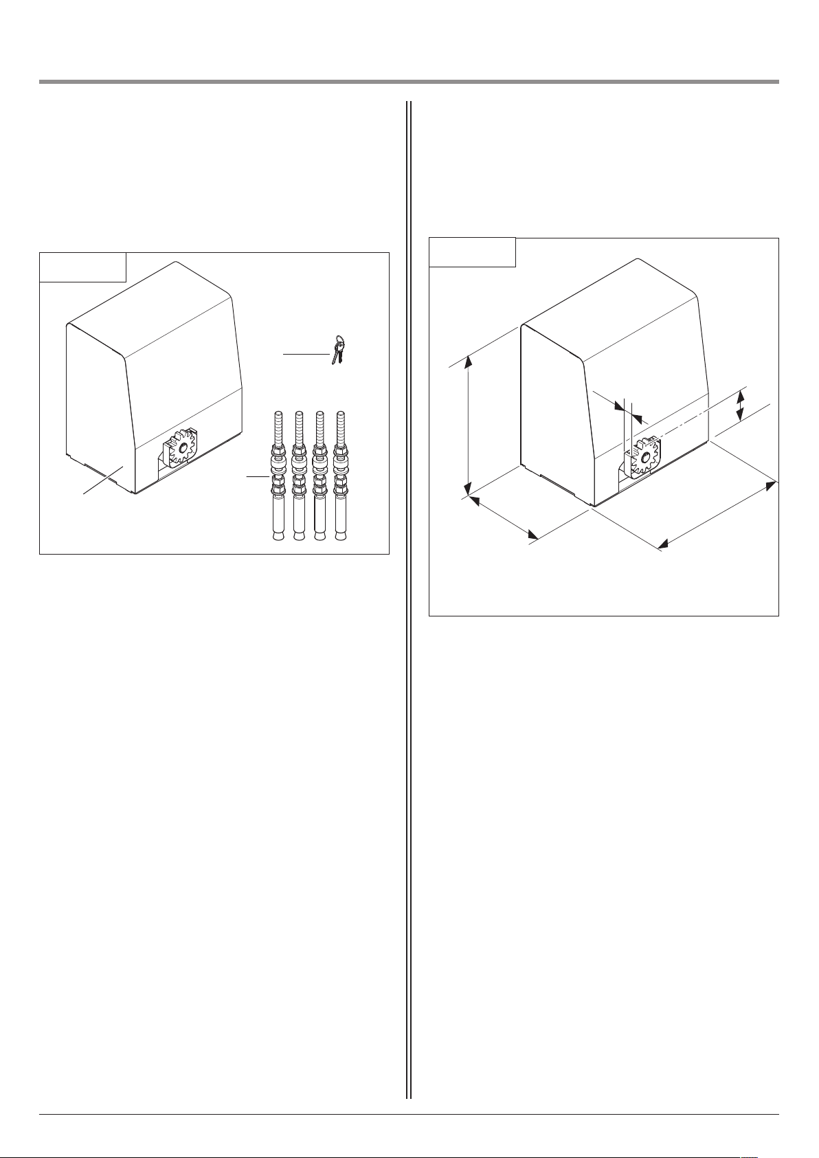
4. Produktübersicht
4.2 Abmessungen4.1 Lieferumfang Dynamic 736, 741 FU
Standard-Lieferumfang
4.1 / 1
2
3
1
1 Motor-Aggregat Dynamic 735, 740 FU
2 Schlüssel
3 Dübelset für Fundamentmontage
Dynamic 736, 741 FU
4.2 / 1
498
264
4
2
148
404
Neben dem Standard-Lieferumfang ist folgendes Zubehör für die
Montage erforderlich:
- Zahnstange (M6 wird empfohlen)
Montage- und Bedienungsanleitung, Dynamic 736, 741 FU D (#116119) 5
Page 6

4. Produktübersicht
5. Montagevorbereitungen
4.3 Torvarianten
Der Standard-Lieferumfang ist für folgende Torvarianten geeignet.
Schienengeführte Toranlage
4.3 / 1
5.1 Allgemeine Angaben
Darstellungen in dieser Anleitung sind nicht maßstabsgetreu.
Größenmaße werden stets in Millimeter (mm) angegeben!
e nach Öffnungsrichtung kann das Motor-Aggregat auf der
J
rechten oder linken Torseite montiert werden.
In dieser Anleitung wird die Montage auf der rechten Seite
dargestellt.
Bei Montage auf der linken Seite muss eine Drehfeldanpassung
für Motor und Steuerung erfolgen.
Folgendes Werkzeug muss für eine ordnungsgemäße Montage
zur Verfügung stehen:
5.1 / 1
19 2 5
Freitragende Toranlage
4.3 / 2
ø 18
1/1
=
=
6 Montage- und Bedienungsanleitung, Dynamic 736, 741 FU D (#116119)
Page 7

5. Montagevorbereitungen
a
a
a
a
a
a
a
a
a
a
a
a
a
a
a
aa
a
a
a
a
a
a
a
a
a
a
aa
a
a
a
a
a
a
a
a
a
a
aaa
a
a
a
a
a
a
a
a
a
a
a
aaa
a
a
a
a
a
a
aa
a
aa
a
a
a
a
a
a
a
a
a
a
a
a
a
a
a
a
a
a
a
a
a
a
a
a
a
aa
a
a
a
a
a
a
a
a
a
a
a
a
aaa
a
a
a
a
a
a
a
a
a
a
a
aa
a
a
a
a
a
a
a
a
a
a
aa
a
a
a
a
a
a
a
a
a
a
aaa
a
a
a
a
a
a
a
a
a
a
a
aaa
a
a
a
a
a
a
aa
a
aa
a
a
a
a
a
a
a
a
a
a
a
a
a
a
a
a
a
a
a
a
a
a
a
a
a
aa
a
a
a
a
a
a
a
a
a
a
a
a
aaa
a
a
a
a
a
a
a
a
a
a
a
aa
a
a
a
a
a
a
a
a
a
a
aa
a
a
a
a
a
a
a
a
a
a
aaa
a
a
a
a
a
a
a
a
a
a
a
aaa
a
a
a
a
a
a
aa
a
aa
a
a
a
a
a
a
a
a
a
a
a
aa
a
a
a
a
a
5.2 Kontrollen
Achtung!
Um eine korrekte Montage zu gewährleisten,
müssen vor Beginn der Arbeiten die folgenden
Kontrollen unbedingt durchgeführt werden.
Lieferumfang
• Prüfen Sie, ob der Lieferumfang vollständig ist.
• Prüfen Sie, ob benötige Zubehörteile für Ihre Einbausituation
vorhanden sind.
Fundament
• Prüfen Sie die vorgesehene Position des Antriebssystems:
- Die Montage des Motor-Aggregats und der Zahnstange
müssen auf der Innenseite bei geschlossenem Tor erfolgen.
• - Das Motor-Aggregat darf nicht in die lichte Durchfahrt (r)
montiert werden.
• - Bei freitragenden Toren muss das Motor-Aggregat mittig
zwischen den Tragrolleneinrichtungen montiert werden.
• - Das Fundament muss für Schwer last dübel geeignet sein.
5.3 Tor- und Fundamentplan
5.3 / 1
q
r
s
B
t
A
• Prüfen Sie, ob ein geeignetes Fundament vorhanden ist.
• Prüfen Sie die Verlegung der Zuleitung.
Achten Sie dabei auf den Kabelaustritt an der Montageposition
des Motor-Aggregats.
Toranlage
• Stellen Sie sicher, dass Ihrer Toranlage ein geeigneter
Stromanschluss und eine Netztrenneinrichtung zur Verfügung
stehen.
• Stellen Sie sicher, dass nur Kabel verwendet werden, die im
Außenbereich geeignet sind (Kältebeständigkeit, UVBeständigkeit).
• Sichern Sie alle Quetsch- und Scherstellen ab, damit das Tor in
Selbsthaltung stehen kann.
• Montieren Sie für die Torposition AUF und Torposition ZU
jeweils einen mechanischen Toranschlag. Die Position muss so
gewählt werden, dass die Schließkante in der Torposition AUF
und Torposition ZU nicht eingedrückt und betätigt wird.
• Prüfen Sie, ob das anzutreibende Tor die folgenden
Bedingungen erfüllt:
- Der Laufweg des Tores muss waagerecht sein,
d.h. keinesfalls mit Gefälle.
• - Das Tor sollte im geschlossenen Zustand auf der Montageseite
die lichte Durchfahrt um mindestens 500 mm überragen.
• - Das Tor muss in beiden Richtungen einen
mechanischen Endanschlag haben.
• - Das Tor muss in sich gerade sein, so dass sich der Abstand
zwischen Motor-Aggregat und Tor nicht verändert.
Montage- und Bedienungsanleitung, Dynamic 736, 741 FU D (#116119) 7
A Leerrohr für Steuerleitung
B Leerrohr für Zuleitung
q Torlänge
r Lichte Durchfahrt
s Öffnungsrichtung
t Frostfreie Tiefe
x Torstärke + Abstand bis Baukörper
=
=
X
260
X
Page 8
i
5. Montagevorbereitungen
6. Montage
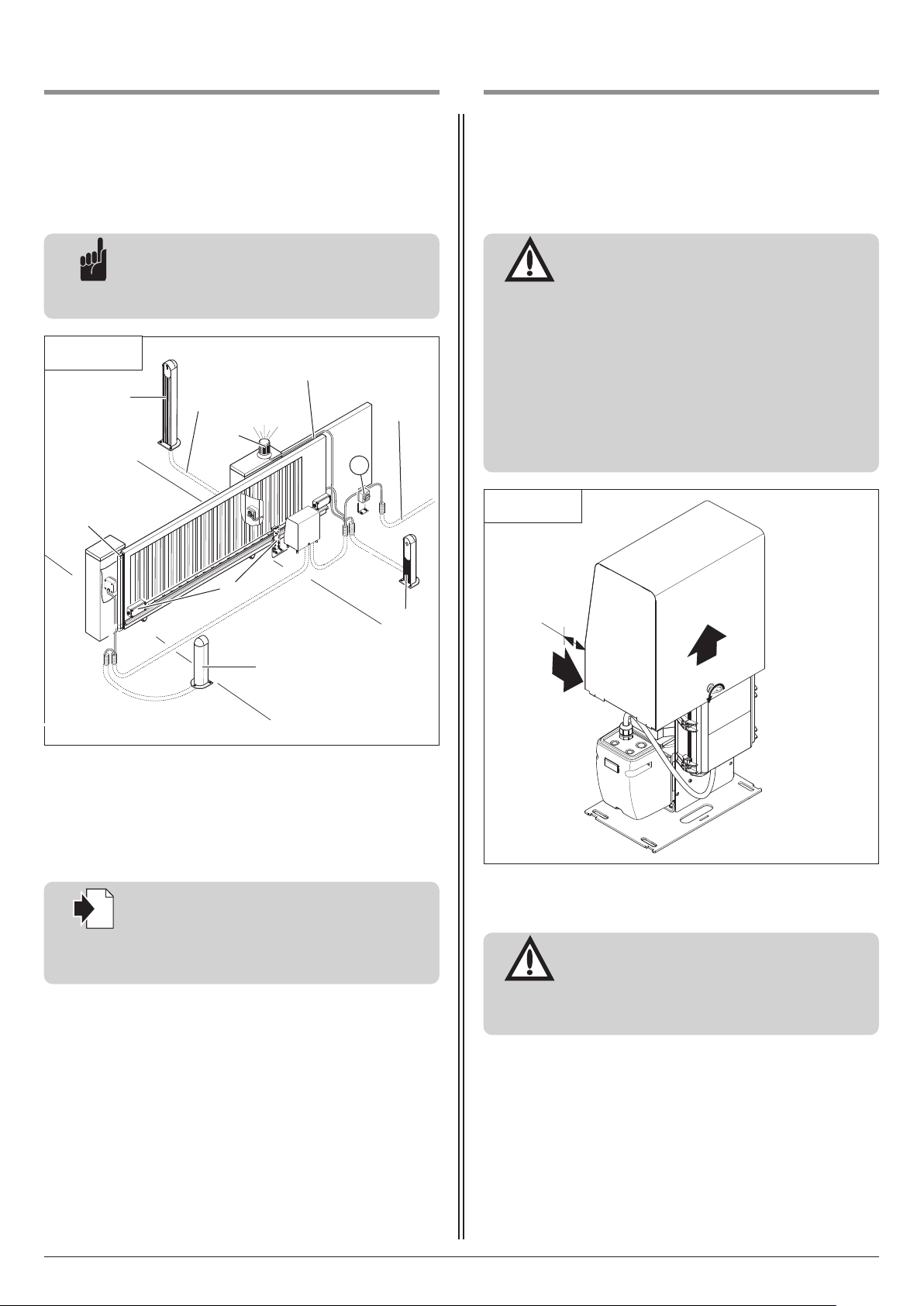
5.4 Verkabelungsplan
Hinweis:
Die Verkabelung ist als Beispiel dargestellt und
kann je nach Tortyp und Ausstattung abweichen.
5.4 / 1
2
x 0,4 mm
2
3
4
3 x 1,5 mm
2
6.1 Montage des Motor-Aggregats
Achtung!
Für eine einwandfreie Montage müssen
folgende Punkte eingehalten werden:
- Das Motor-Aggregat muss zum Tor
ausgerichtet werden, damit das Stirnrad in
jeder Torposition in die Zahnstange greift.
2
3 x 1,5 mm
230 V AC /
400 V
2
5
6.1 / 1
- Die Dübel für die Bodenmontage müssen
mindestens 150 mm Abstand zum
undament rand haben.
F
- Nach Abschluss der Montage und der
Inbetriebnahme müssen alle Abdeckungen
wieder auf das Motor-Aggregat montiert
werden.
1
6
1 Signalübertragungssystem
2 Schlüsseltaster / Special 750
3 Signalleuchte
4 Schließkantensicherung (SKS)
5 Hauptschalter (Netztrenneinrichtung)
6 Lichtschranke
Verweis:
Für die Montage und Verkabelung der
Torsensoren, Bedien- und Sicherheitselemente
sind die entsprechenden Anleitungen zu
berücksichtigen.
6
~
5
• Entfernen Sie die Abdeckung am Motor-Aggregat.
Achtung!
Für eine einwandfreie Montage muss das
Motor-Aggregat bei freitragenden Toren mittig
zwischen den Tragrollen einrichtungen montiert
werden.
8 Montage- und Bedienungsanleitung, Dynamic 736, 741 FU D (#116119)
Page 9

6. Montage
a
a
a
a
a
a
a
a
a
a
a
a
aaa
a
a
a
a
a
a
a
a
a
a
a
aa
a
a
a
a
a
a
a
a
a
a
aa
a
a
a
a
a
a
a
a
a
a
aaa
a
a
a
a
a
a
a
a
a
a
a
aaa
a
a
a
a
a
a
aa
a
aa
a
a
a
a
a
a
a
a
a
a
a
aa
a
a
a
a
a
i
i
6.1 / 2
E
G
r
180
50
1
50
C Mauer
D Tor
E Anschraubfläche der Zahnstange
F Leerrohr für Zuleitung / Steuerleitung
G Fundament
H Vorderkante vorhandene Zahnstange
r Lichte Durchfahrt
C
D
H
F
360
404
Vorsicht!
Stromschlaggefahr:
Vor Verkabelungs arbeiten ist sicherzustellen,
dass die Leitungen spannungsfrei sind.
Während der Verkabelungs arbeiten ist sicherzustellen, dass die Leitungen spannungsfrei blei-
X
70
260
176
22
6.1 / 3
en (z. B. Wieder einschalten verhindern).
b
Achtung!
- Um eine einwandfreie Montage des MotorAggregats zu gewährleisten, muss das
Fundament ausgehärtet sein, bevor die
Montagedübel eingesetzt werden.
- Um die Schutzart der Steuerung zu gewähr -
eisten, müssen die Leitungen durch den pas-
l
senden Verschraubungs einsatz geführt werden.
• Ermitteln Sie den Abstand von der Anschraubfläche der
Zahnstange (E) zum Motor-Aggregat. Beachten Sie dabei das
Maß X.
Special 475: X = 100
Verweis:
Bei der Ermittlung der Anschraubfläche der
Zahnstange sind die Angaben in Punkt 6.2.2 zu
beachten.
Hinweis:
- Bei der Nutzung einer vorhandenen
Zahnstange gilt das Maß 70 mm von der
ersten Verschraubung bis zur Vorderkante der
Zahnstange.
- Die Bodenkonsole kann wahlweise auf dem
Fundament verschraubt oder in das
Fundament eingelassen werden.
• Prüfen Sie vor der Montage des Motor-Aggregats, ob die
mögliche Höhen verstellung (ca. 50 mm) für Ihre Einbau situation
ausreicht oder ob das Motor-Aggregat unterfüttert werden
muss.
• Richten Sie die Bodenkonsole parallel zum Tor aus.
95 – 100
J
• Bohren Sie die Löcher für die Dübel nach vorgegebenem
Bohrbild.
• Stecken Sie die Dübel ein.
• Führen Sie die Zuleitung (J) in das Motor-Aggregat.
• Richten Sie das Motor-Aggregat aus.
• Verschrauben Sie das Motor-Aggregat.
Verweis:
Montage- und Bedienungsanleitung, Dynamic 736, 741 FU D (#116119) 9
Die Höheneinstellung des Motor-Aggregats ist
in Punkt 6.3 beschrieben.
Page 10
i
6. Montage
i
.2 Montage der Zahnstange
6
6.2.1 Allgemeines
Achtung!
Für eine einwandfreie Montage müssen
folgende Punkte zutreffen:
- Das Motor-Aggregat ist montiert.
- Das Motor-Aggregat ist entriegelt.
Verweis:
Bei vorhandener Zahnstange geht die
Montage bei Punkt 6.3 weiter.
- Die Entriegelung des Motor-Aggregats ist in
Punkt 6.4 beschrieben.
Minimale Zahnstangenlänge
Die minimale Zahnstangenlänge entspricht dem Bewegungshub
des Tores zwischen der Torposition ZU und der Torposition
AUF + 180 mm.
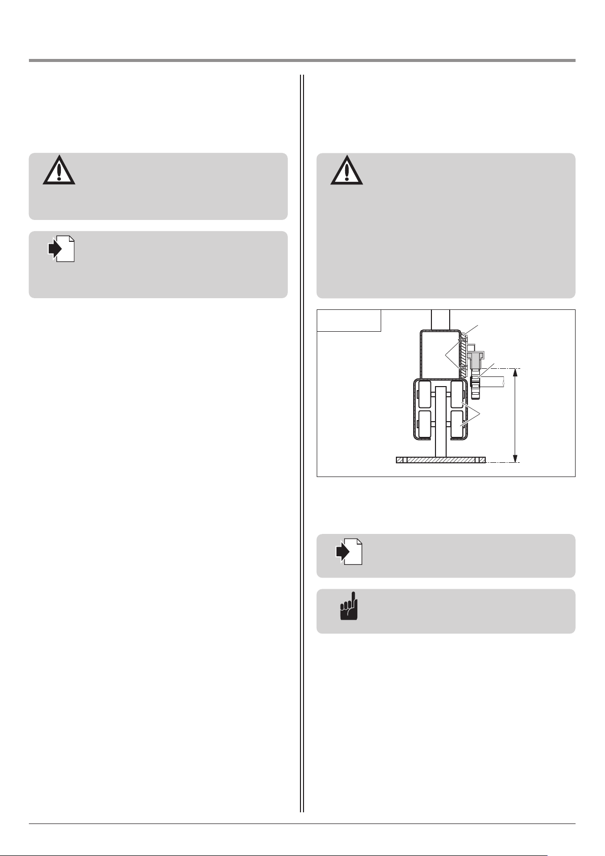
6.2.2 Bestimmung der Montagehöhe
Achtung!
Für einen einwandfreien Torlauf müssen
folgende Punkte zutreffen:
- Die Schrauben (A) dürfen nicht die Funktion
des Tores beeinträchtigen
(z. B. in die Laufbahn der Torrollen (B)
hineinragen).
- Das Stirnrad (C) darf nicht am Tor anliegen.
Das Stirnrad (C) darf nicht in der untersten
Position stehen (das Stirnrad muss nach der
Zahn stangen montage 1 - 2 mm absenkbar
sein).
6.2.2 / 1
A
D
C
B
190 – 240
• Legen Sie die Montagehöhe der Zahnstange am Tor fest.
• Stellen Sie das Stirnrad auf die passende Höhe ein.
Verweis:
Die Höheneinstellung des Motor-Aggregats ist
in Punkt 6.3 beschrieben.
Hinweis:
Durch eine Unterfütterung (D) kann die
Zahnstange an das Tor angepasst werden.
10 Montage- und Bedienungsanleitung, Dynamic 736, 741 FU D (#116119)
Page 11
i
6. Montage
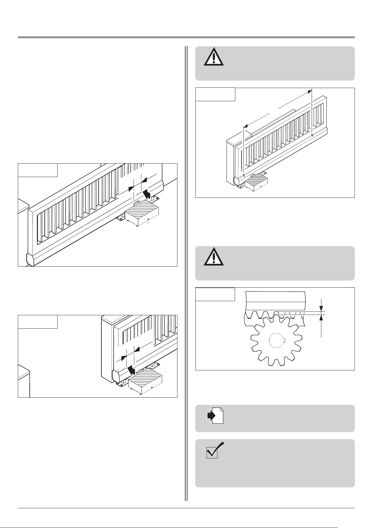
6.2.3 Bestimmung von Zahnstangenlänge und
Montageposition
Maximale Zahnstangenlänge
Bei einer Montage der Zahnstange über die gesamte Torlänge
muss keine Montageposition bestimmt werden. Die Länge und die
ontageposition der Zahnstange entspricht der Torbreite.
M
Minimale Zahnstangenlänge
Die minimale Zahnstangenlänge muss am Tor ermittelt werden.
Achtung!
Um eine einwandfreie Funktion zu gewährleisten,
muss die Zahnstange mindestens den Bereich (E)
zwischen den Markierungen abdecken.
6.2.3 / 3
E
6.2.3 / 1
• Bewegen Sie das Tor in die Torposition ZU.
• Setzen Sie eine Markierung auf das Tor:
90 mm von Mitte Stirnrad in Richtung Tor AUF.
6.2.3 / 2
90
0
9
6.2.4 Motor-Aggregat anpassen
Achtung!
Für einen reibungslosen Torlauf ist es wichtig,
dass zwischen Zahnstange und Stirnrad ein
Abstand von 1 – 2 mm einge halten wird.
6.2.4 / 1
1 – 2
Für die Anpassung ist eine erneute Höheneinstellung erforderlich.
• Senken Sie das Stirnrad 1 - 2 mm ab.
• Bewegen Sie das Tor in die Torposition AUF.
• Setzen Sie eine Markierung auf das Tor:
90 mm von Mitte Stirnrad in Richtung Tor ZU.
Verweis:
Die Höheneinstellung des Motor-Aggregats ist
in Punkt 6.3 beschrieben.
Kontrolle:
Um zu prüfen, dass sich die Zahnstange auf
ganzer Länge im Eingriff mit dem Stirn rad
befindet, muss das Tor einmal in Torposition
AUF und einmal in Torposition ZU geschoben
werden.
Montage- und Bedienungsanleitung, Dynamic 736, 741 FU D (#116119) 11
Page 12
6. Montage
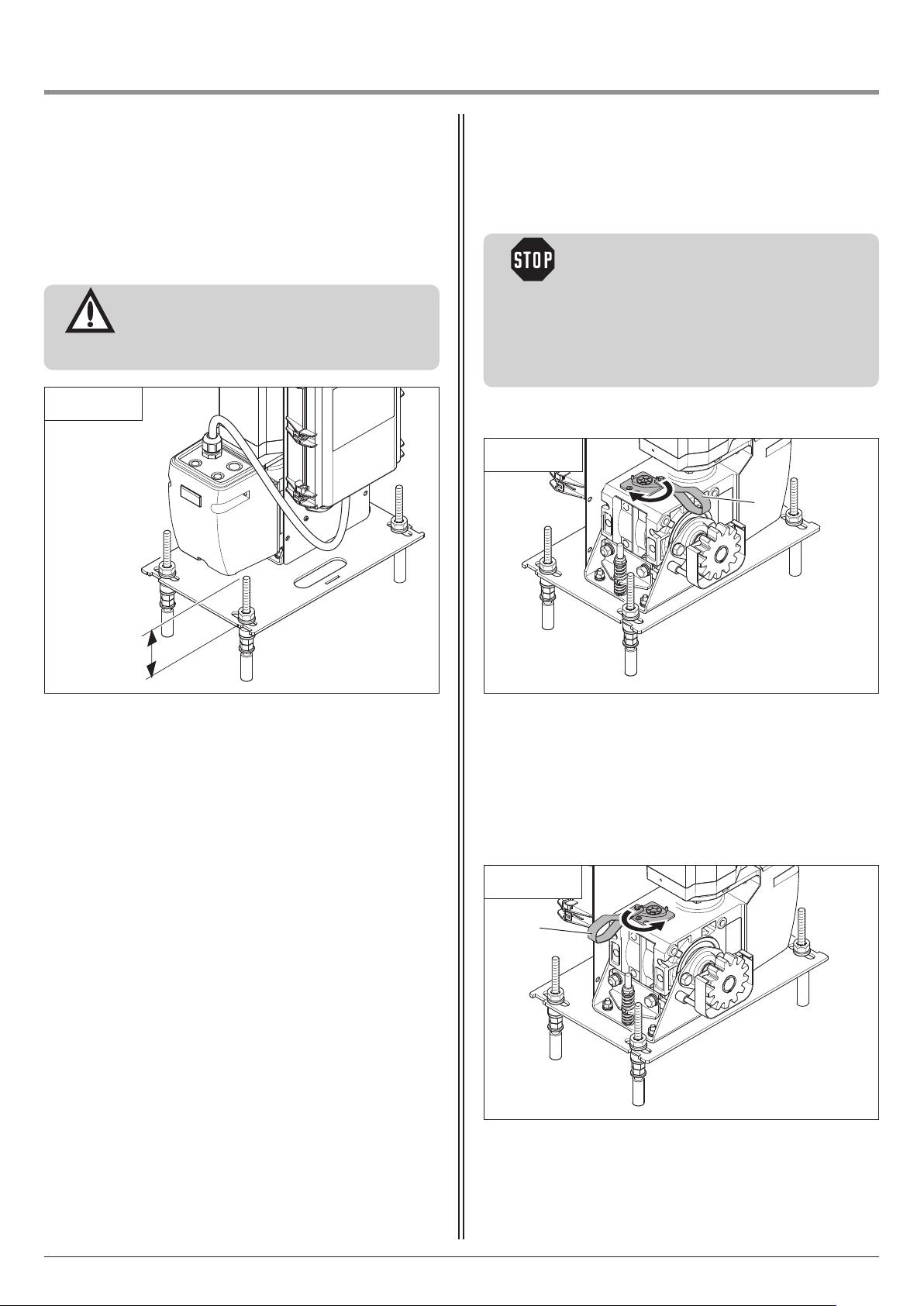
6.3 Höhenanpassung des Motor-Aggregats
Das Motor-Aggregat kann in der Höhe angepasst werden.
Achtung!
Für einen reibungslosen Torlauf ist es wichtig,
dass Zahnrad und Zahnstange korrekt ineinander greifen.
6.3 / 1
6.4 Entriegelung
Vorsicht!
Um Personenschäden zu vermeiden:
- Darf eine Notbedienung nur aus einem
sicheren Stand heraus erfolgen.
- Darf sich während der Bedienung keine
Person im Gefahrenbereich des Tores befindet.
- Darf eine Bedienung nur von geschultem
Fachpersonal durchgeführt werden.
Motor-Aggregat entriegeln
6.4 / 1
A
< 50
• Lösen Sie die Schraubverbindungen.
• Stellen Sie das Motor-Aggregat auf die passende Höhe ein.
• Ziehen Sie die Schraubverbindungen fest.
• Ziehen Sie die Schlaufe (A) nach links.
Tor bewegen
Das Tor lässt sich von Hand AUF und ZU bewegen.
Motor-Aggregat verriegeln
6.4 / 2
A
• Ziehen Sie die Schlaufe (A) nach rechts.
12 Montage- und Bedienungsanleitung, Dynamic 736, 741 FU D (#116119)
Page 13

i
6. Montage
i
7. Inbetriebnahme
6.5 Steuerungsanschlüsse
Verweis:
Für die Montage und Verkabelung der
Steuerung ist die entsprechende Anleitung zu
berücksichtigen.
Verweis:
Die Inbetriebnahme und Programmierung der
Anlage ist in der Anleitung der Steuerung
beschrieben.
Montage- und Bedienungsanleitung, Dynamic 736, 741 FU D (#116119) 13
Page 14
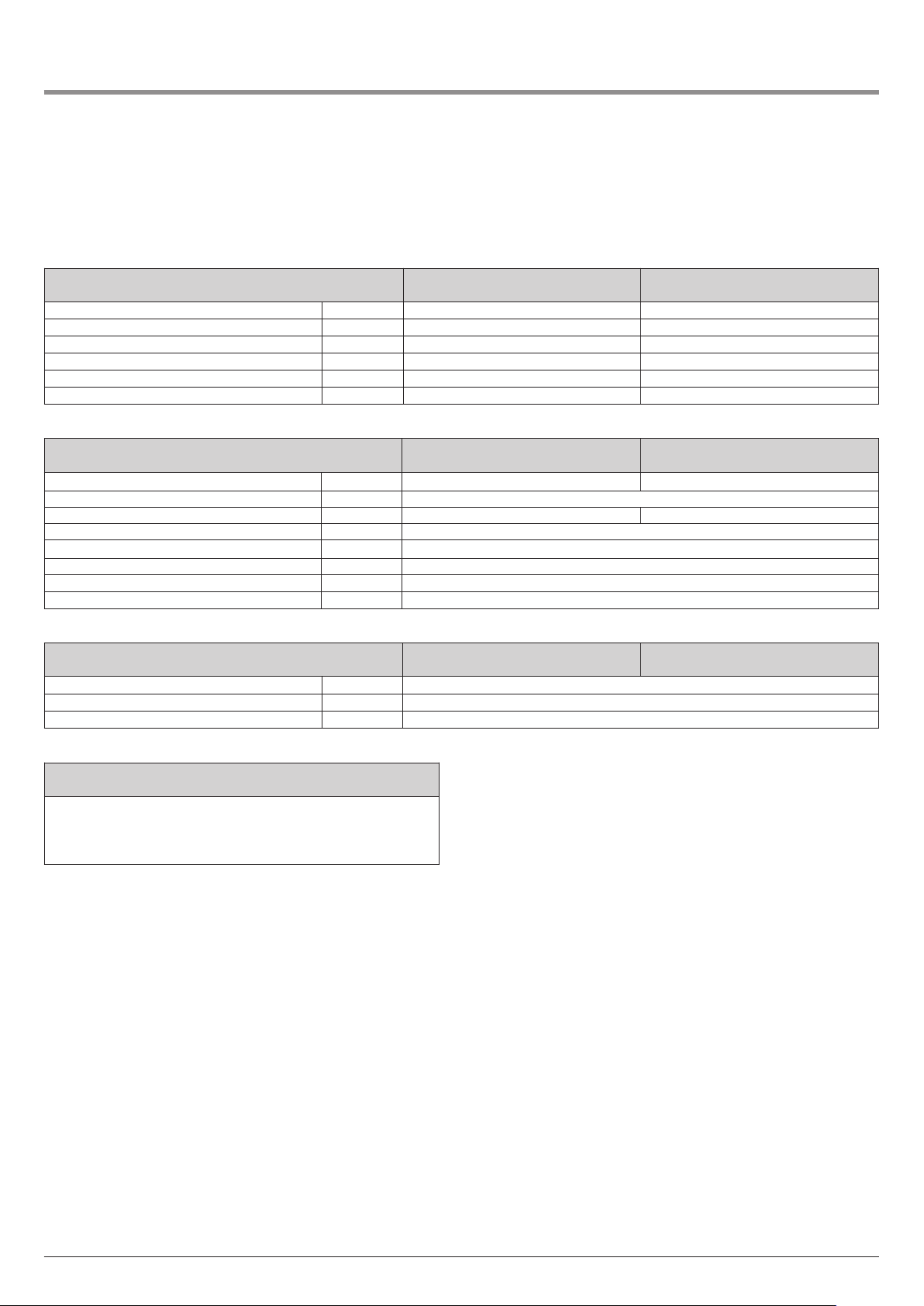
8. Anhang
8.1 Technische Daten Dynamic 736, 741 FU
Mechanische Daten / Typ
Abtriebsdrehmoment Nm 80 100
Nenndrehzahl min
max. Umdrehung, Abtriebswelle 76 76
Notbedienung Entriegelung Entriegelung
Hohlwellendurchmesser mm 25,4 25,4
Laufgeschwindigkeit bei 50 Hz mm/Sek. 180 120
Elektrische Daten / Typ
Nennspannung V Y 3N~ 400 1N~ 230
Nennfrequenz Hz 50
Stromaufnahme A Y 1,9 3,3
Motorleistung kW 0,55
Motor-Einschaltdauer (ED) % S 3 - 60
Versorgung externer Elemente V 24 / 500 mA
Schutzart IP 65
Schutzklasse I
Umgebungsdaten / Typ
Abmessungen mm 404 x 498 x 306
Gewicht kg 27,0
Temperaturbereich C˚ -20 bis +60
-1
Dynamic 736
80/45
45 30
Dynamic 736
80/45
Dynamic 736
80/45
Dynamic 741 FU
100/30
Dynamic 741 FU
100/30
Dynamic 741 FU
100/30
Anwendung
Universell einsetzbar für Tore bis max. 18 m Breite
und
- max. 1.100 kg Gewicht (Dynamic 736)
- max. 1.300 kg Gewicht (Dynamic 741 FU)
14 Montage- und Bedienungsanleitung, Dynamic 736, 741 FU D (#116119)
Page 15
8. Anhang
8.2 Erklärung für den Einbau einer
unvollständigen Maschine
(Einbauerklärung im Sinne der EG-Maschinenrichtlinie
2006/42/EG gemäß Anhang II, Teil 1 B)
ersteller:
H
Marantec Antriebs und Steuerungstechnik GmbH & Co.
KGRemser Brook 11, 33428 Marienfeld, Germany
Die unvollständige Maschine (Produkt):
Schiebetorantrieb Dynamic 736, 741 FU
ist entwickelt, konstruiert und gefertigt in Übereinstimmung mit
der:
– EU-Richtlinie Maschinen 2006/42/EG
– EU-Richtlinie RoHS 2011/65/EU
– EU-Richtlinie Niederspannung 2014/35/EU
– EU-Richtlinie Elektromagnetische Verträglichkeit 2014/30/EU
– RED-Richtlinie 2014/53/EU
Angewandte und herangezogene Normen und Spezifikationen:
– EN ISO 13849-1, PL „c“, Cat. 2
Sicherheit von Maschinen - Sicherheitsbezogene Teile von
Steuerungen - Teil 1: Allgemeine Gestaltungsleitsätze
– EN 60335-2-103
Sicherheit elektrischer Geräte für den Hausgebrauch und
ähnliche Zwecke –Besondere Anforderungen für Antriebe für
Tore, Türen und Fenster.
– EN 61000-6-3/2
Elektromagnetische Verträglichkeit – Störaussendung und
Störfestigkeit
Für die Zusammenstellung der technischen Unterlagen ist
bevollmächtigt:
Marantec Antriebs- und Steuerungstechnik GmbH & Co. KG,
emser Brook 11 · 33428 Marienfeld · Germany
R
Fon +49 (5247) 705-0
Gültigkeitsbereich dieser Einbauanleitung:
Produktionsdatum 01.10.2016 - 30.09.2017
01.02.2016 M. Hörmann
Geschäftsleitung
Folgende Anforderungen der EG-Richtlinie 2006/42/EG werden
eingehalten:
Allgemeine Grundsätze, Nr. 1.1.2, 1.1.3, 1.1.5, 1.1.6, 1.2.1,
1.2.2, 1.2.3, 1.2.6, 1.3.1, 1.3.4, 1.3.7, 1.3.8, 1.3.9, 1.4.1, 1.4.3,
1.5.1, 1.5.4, 1.5.6, 1.5.8, 1.5.14, 1.7
Ferner erklären wir, dass die speziellen technischen Unterlagen
für diese unvollständige Maschine nach Anhang VII Teil B erstellt
wurden und verpflichten uns, diese auf begründetes Verlangen
den einzelstaatlichen Stellen elektronisch zu übermitteln.
Diese unvollständige Maschine ist nur zum Einbau in eine
Toranlage bestimmt, um somit eine vollständige Maschine im
Sinne der Maschinenrichtlinie 2006/42/EG zu bilden. Die
Toranlage darf erst in Betrieb genommen werden, wenn
festgestellt wurde, dass die gesamte Anlage den Bestimmungen
der o.g. EG-Richtlinien entspricht.
Bei einer nicht autorisierten Änderung des Produktes verliert diese
Erklärung ihre Gültigkeit.
Montage- und Bedienungsanleitung, Dynamic 736, 741 FU D (#116119) 15
Page 16
1. Meaning of symbols
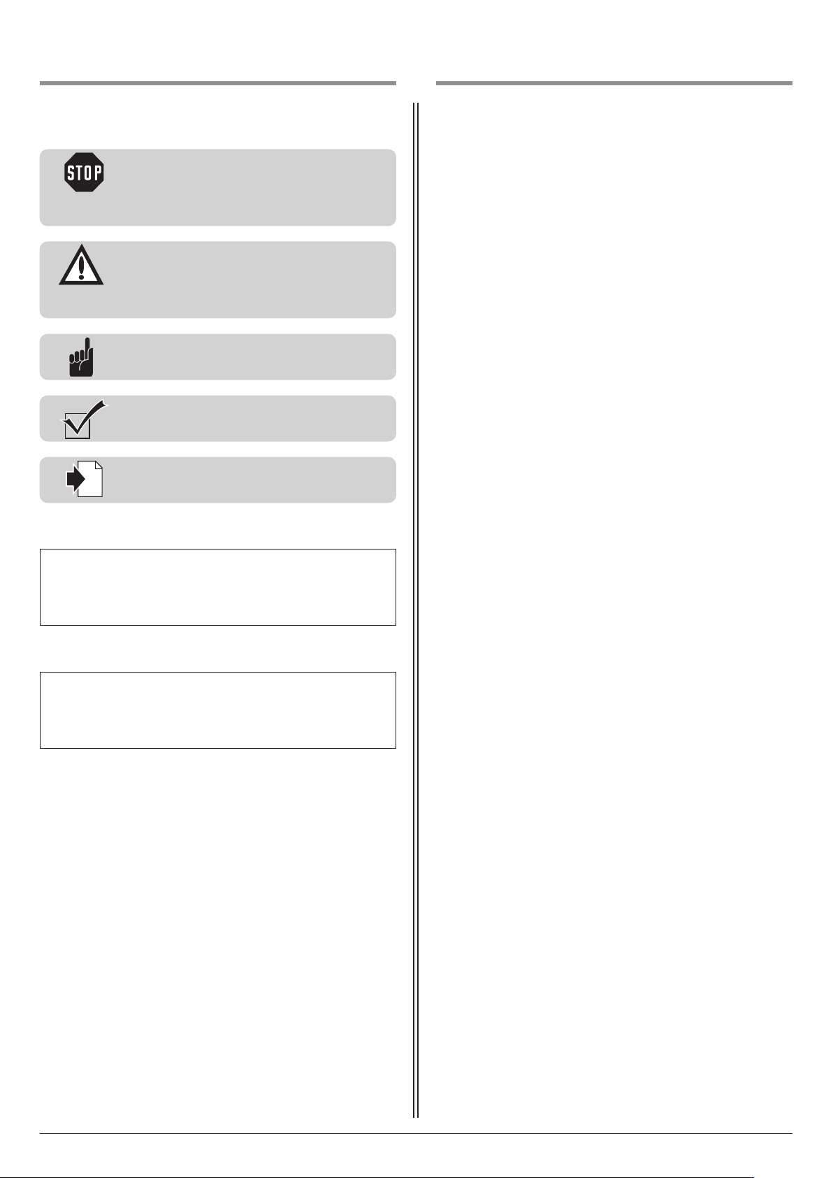
i
2. Table of contents
Advice
Caution!
Danger of personal injury!
The following safety advice must be observed
t all times so as to avoid personal injury!
a
Attention!
Danger of material damage!
The following safety advice must be observed
at all times so as to avoid material damage!
Advice / Tip
Check
Reference
1. Meaning of symbols . . . . . . . . . . . . . . . . . . . . . . . .16
2. Table of contents . . . . . . . . . . . . . . . . . . . . . . . . . . .16
3. General safety advice . . . . . . . . . . . . . . . . . . . . . . .17
4. Product overview . . . . . . . . . . . . . . . . . . . . . . . . . . .19
4.1 Dynamic 736, 741 FU supply package . . . . . . .19
.2 Dimensions . . . . . . . . . . . . . . . . . . . . . . . . . . .19
4
4.3 Gate variations . . . . . . . . . . . . . . . . . . . . . . . .20
5. Preparation for mounting . . . . . . . . . . . . . . . . . . . .20
5.1 General notes . . . . . . . . . . . . . . . . . . . . . . . . .20
5.2 Checks . . . . . . . . . . . . . . . . . . . . . . . . . . . . . . .21
5.3 Gate and foundation layout . . . . . . . . . . . . . . .21
.4 Cabling layout . . . . . . . . . . . . . . . . . . . . . . . . .22
5
6. Installation . . . . . . . . . . . . . . . . . . . . . . . . . . . . . . . .22
6.1 Installing the motor unit . . . . . . . . . . . . . . . . .22
6.2 Mounting the toothed rack . . . . . . . . . . . . . . .24
6.3 Adjusting the height of the motor unit . . . . . .26
6.4 Release mechanism . . . . . . . . . . . . . . . . . . . . .26
6.5 Connection of control elements . . . . . . . . . . . .27
7. Initial operation . . . . . . . . . . . . . . . . . . . . . . . . . . . .27
8. Attachment . . . . . . . . . . . . . . . . . . . . . . . . . . . . . . . .28
8.1 Technical data for Dynamic 736, 741 FU . . . . .28
8.2 Declaration for the incorporation of a partly
completed machine . . . . . . . . . . . . . . . . . . . . .29
Type plate on control unit
Type: ____________________________________________________
Art. No.: _________________________________________________
Product No.: ______________________________________________
Type plate on motor unit
Type: ____________________________________________________
Art. No.: _________________________________________________
Product No.: ______________________________________________
16 Manual for installation and operation, Dynamic 736, 741 FU GB (#116119)
Page 17

3. General safety advice
Please read carefully!
Target group
– Installation, connection, setting in operation and servicing:
qualified, trained specialist personnel.
– Operation, inspection and servicing:
the operator of the door system.
Requirements to be met by qualified and trained specialist staff:
– Knowledge of the general and specific safety and accident- prevention
regulations.
– they have knowledge of the relevant electrical regulation,
– Training in the use and care of appropriate safety equipment.
– Adequate instruction and supervision by qualified electricians.
– The ability to recognise hazards that can be caused by electricity.
– Knowledge of the application of the following standards
– EN 12635 (“Doors and gates - Installation and use”),
– EN 12453 (“Safety in use of power operated doors - Requirements”),
– EN 12445 (“Safety in use of power operated doors - Test methods”),
– EN 13241-1 (“Industrial, commercial and garage doors and gates -
Part 1: Products without fire resistance or smoke control
characteristics”)
Requirements to be met by the operator of the door system:
– Knowledge and safekeeping of the instruction manual.
– Safe and proper keeping of the inspection logbook.
– Knowledge of general safety and accident-prevention regulations.
– Instruction of all persons who use the door system.
– Ensure that the door system is serviced and maintained periodically by
qualified and trained professionals.
Special requirements apply to the following users:
– Children aged eight and above.
– Persons with with reduced physical, sensory or mental capabilities.
– Persons with a lack of experience and knowledge.
These users are only authorised to operate the device.
Special requirements:
– The users must be supervised.
– The users must have been briefed on how to use the device.
– The users must understand the dangers involved in handling the device.
– Children are not allowed to play with the device.
Warranty
For an operations and safety warranty, the advice in this instruction
manual has to be observed. Disregarding these warnings may lead
to personal injury or material damage. If this advice is disregarded, the
manufacturer will not be liable for damages that might occur.
Power-operated windows, doors and gates must be checked by an expert
(and this must be documented) before they are put into operation and
thereafter as required, but at least once a year.
Correct use
The operator system is designed exclusively for opening and closing
sliding doors and gates.
Gate requirements
The Dynamic 736 operator system is suitable for:
- Sliding gates weighing up to 1,100 kg.
The Dynamic 741 FU operator system is suitable for:
- Sliding gates weighing up to 1,300 kg.
The gate must have:
- mechanical gate stops in both directions,
- a straight and even travel path, i.e. with absolutely no slope.
Beside the advice in these instructions, please observe the general
safety and accident prevention regulations!
Our sales and supply terms and conditions are effective.
Information on installing the operator system
• Ensure that the gate is in good mechanical condition.
• Ensure that the gate can stop in any position.
• Ensure that the gate can be easily moved in the OPEN and CLOSE
directions.
• Ensure that the gate opens and closes properly.
• Remove all unnecessary components from the gate (e.g. cables, chains,
brackets).
• Render any installations inoperable that will no longer be needed after
the operator system has been installed.
• Before commencing cabling works it is very important to disconnect the
operator system from the electricity supply.
Ensure that the electricity supply remains disconnected throughout the
cabling works.
• Adhere to the local protection regulations.
• Lay the electricity supply cables and control cables; these MUST be laid
separately. The controls voltage is 24 V DC.
• Install the operator system with the gate in the CLOSED position.
• Install all the impulse transmitters and control devices (e.g. remote
control buttons) within sight of the gate and at a safe distance from the
moving parts of the gate. A minimum installation height of 1.5 m must
be observed.
• Ensure that no part of the gate extends across public footways or roads
when the installation is complete.
Batteries, fuses and bulbs are excluded from warranty.
To avoid installation errors and damage to the gate and operator system,
it is imperative that the installation instructions are followed. The system
may only be used after thoroughly reading the respective mounting and
installation instructions.
The installation and operating instructions are to be given to the gate
system user, who must keep them safe. They contain important advice for
operation, checks and maintenance.
This item is produced according to the directives and standards
mentioned in the Manufacturer's Declaration and in the Declaration of
Conformity. The product has left the factory in perfect condition with
regard to safety.
Information on commissioning the operator system
After initial operation, the persons responsible for operating the gate
system, or their representatives must be familiarised with the use of the
system.
• Make sure that children cannot access the gate control unit.
• Before moving the gate, make sure that there are neither persons nor
objects in the operating range of the gate.
• Test all existing emergency command devices.
• Never insert your hands into a running gate or moving parts.
• Pay attention to any parts of the gate system that could cause crushing
or shearing damage or accidents.
The EN 13241-1 regulations must be observed.
Manual for installation and operation, Dynamic 736, 741 FU GB (#116119) 17
Page 18

3. General safety advice
Please read carefully!
Information on servicing the operator system
Maintenance work by the operator
Damage or wear to a door system must only be rectified by qualified and
trained professionals.
To ensure fault-free operation, the gate system must be inspected regularly and, if necessary, be repaired. Before starting work on the gate system,
the operator system must always be disconnected from the power supply.
• Check once a month that the operator system reverses when the gate
touches an obstacle. Place an obstacle in the path of the gate to check
this.
• Check all the moving parts of the gate system and gate operator
system.
• Check the gate system for signs of damage or wear and tear.
• Move the gate manually to check that the gate travels easily and
smoothly.
• Check that the photocell functions properly.
• Check that the closing edge safety device functions properly.
• Check the power supply cable for signs of damage.For safety reasons,
if the power supply cable is damaged it must be replaced by the
manufacturer or his customer service department, or by a similarly
qualified person.
Maintenance work by qualified and trained professionals
Power-operated windows, doors and gates must be inspected by qualified
and trained professionals whenever necessary, but at least once a year
(written inspection records must be kept).
• Test the driving power with a force tester designed for this purpose.
• Replace any damaged or worn parts.
Information on cleaning the operator system
• It is vital that you disconnect the operator system from the power
supply before cleaning. Take measures to ensure that the power supply
remains disconnected for the duration of the cleaning operation.
Never use water jets, high pressure cleaners, acids or bases for cleaning.
18 Manual for installation and operation, Dynamic 736, 741 FU GB (#116119)
Page 19
4. Product overview
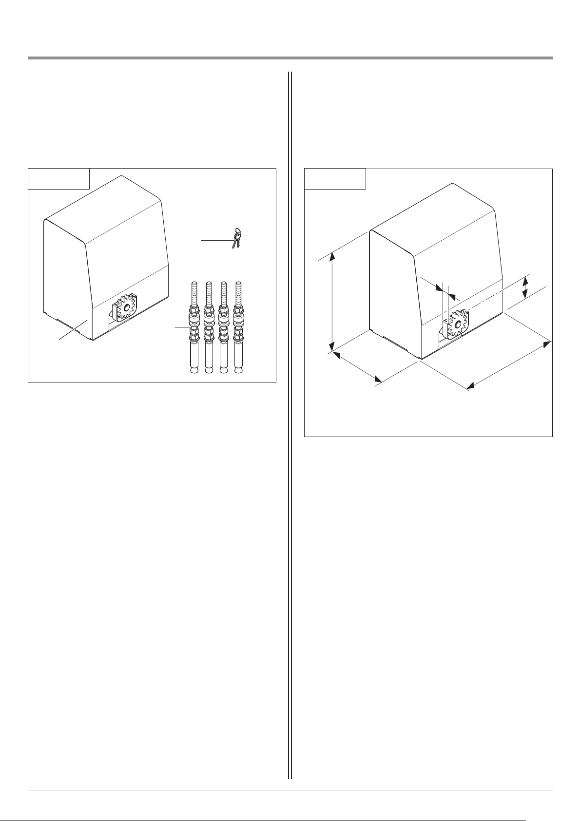
4.2 Dimensions4.1 Dynamic 736, 741 FU supply package
Standard package
4.1 / 1
2
3
1
1 Dynamic 735, 740 FU motor unit
2 Wrench
3 Wall plug set for foundation mounting
Dynamic 736, 741 FU
4.2 / 1
5
498
264
4
2
148
404
50
In addition to the components in the standard package, the
following is required for the installation:
- toothed rack (M6 is recommended)
Manual for installation and operation, Dynamic 736, 741 FU GB (#116119) 19
Page 20
4. Product overview
5. Preparation for mounting
4.3 Gate variations
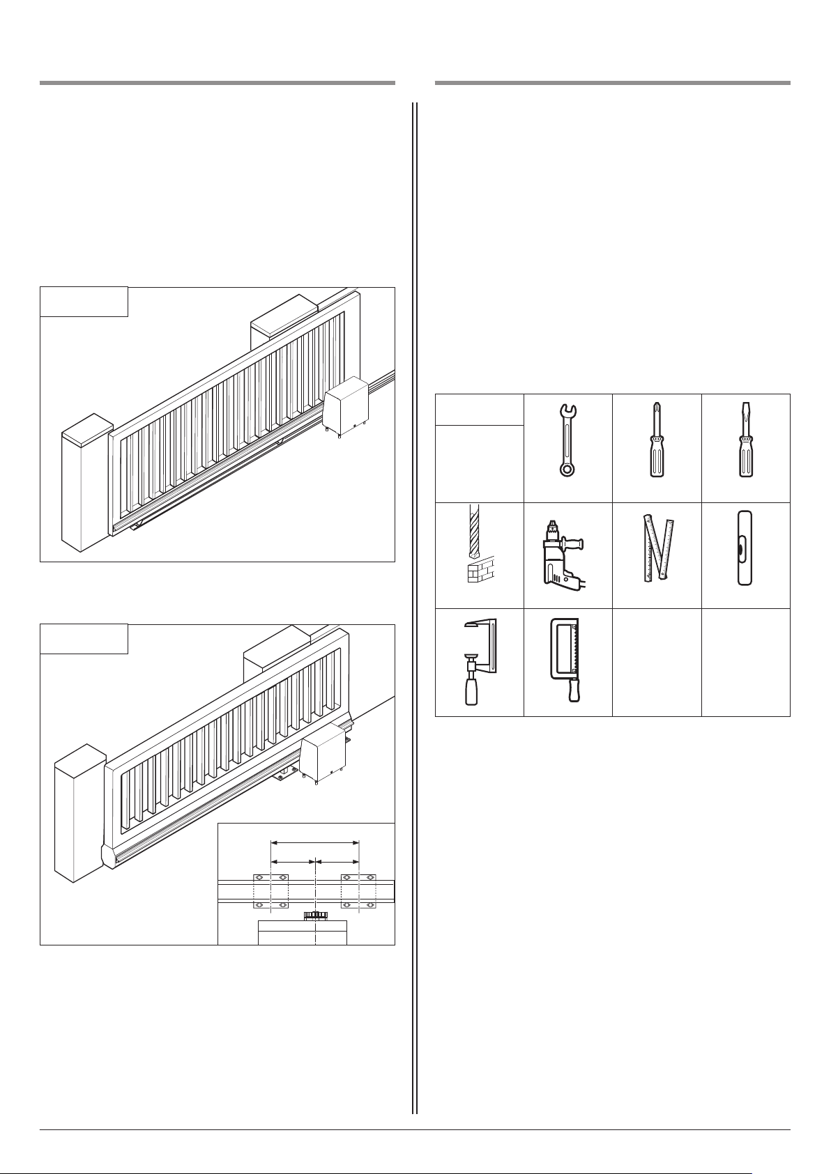
The standard supply package is suitable for
the following types of gate.
ate system on rails
G
4.3 / 1
5.1 General notes
The pictures in these instructions are not true-to-scale.
Dimensions are always given in millimetres (mm)!
he motor can be mounted on the right or left hand side of the
T
gate depending on the direction of opening.
These instructions show the motor being installed on the right
hand side.
If installed on the left-hand side, the rotational field for motor
and controls must be adapted accordingly.
For correct mounting you will need the following tools:
5.1 / 1
19 2 5
Cantilevered gate system
4.3 / 2
ø 18
1/1
=
=
20 Manual for installation and operation, Dynamic 736, 741 FU GB (#116119)
Page 21
5. Preparation for mounting
a
a
a
a
a
a
a
a
a
a
a
a
a
a
a
aa
a
a
a
a
a
a
a
a
a
a
aa
a
a
a
a
a
a
a
a
a
a
aaa
a
a
a
a
a
a
a
a
a
a
a
aaa
a
a
a
a
a
a
aa
a
aa
a
a
a
a
a
a
a
a
a
a
a
a
a
a
a
a
a
a
a
a
a
a
a
a
a
aa
a
a
a
a
a
a
a
a
a
a
a
a
aaa
a
a
a
a
a
a
a
a
a
a
a
aa
a
a
a
a
a
a
a
a
a
a
aa
a
a
a
a
a
a
a
a
a
a
aaa
a
a
a
a
a
a
a
a
a
a
a
aaa
a
a
a
a
a
a
aa
a
aa
a
a
a
a
a
a
a
a
a
a
a
a
a
a
a
a
a
a
a
a
a
a
a
a
a
aa
a
a
a
a
a
a
a
a
a
a
a
a
aaa
a
a
a
a
a
a
a
a
a
a
a
aa
a
a
a
a
a
a
a
a
a
a
aa
a
a
a
a
a
a
a
a
a
a
aaa
a
a
a
a
a
a
a
a
a
a
a
aaa
a
a
a
a
a
a
aa
a
aa
a
a
a
a
a
a
a
a
a
a
a
aa
a
a
a
a
a
5.2 Checks
Attention!
In order to guarantee correct mounting, carry
out the following checks before installing.
Supply package
• Check the package to ensure that all the parts are included.
• Check that you have all the additional components that are
necessary for your particular installation requirements.
Foundations
• Check the proposed installation location for the operator
system:
- The motor unit and the toothed rack must be installed on the
inside of the gate with the gate closed.
- The motor unit should not be installed within the clear
width (r)!
- For cantilevered gates, the motor unit must be mounted at
the mid point between the carrier roller assemblies.
- The foundations must be suitable for heavy-duty wall plugs.
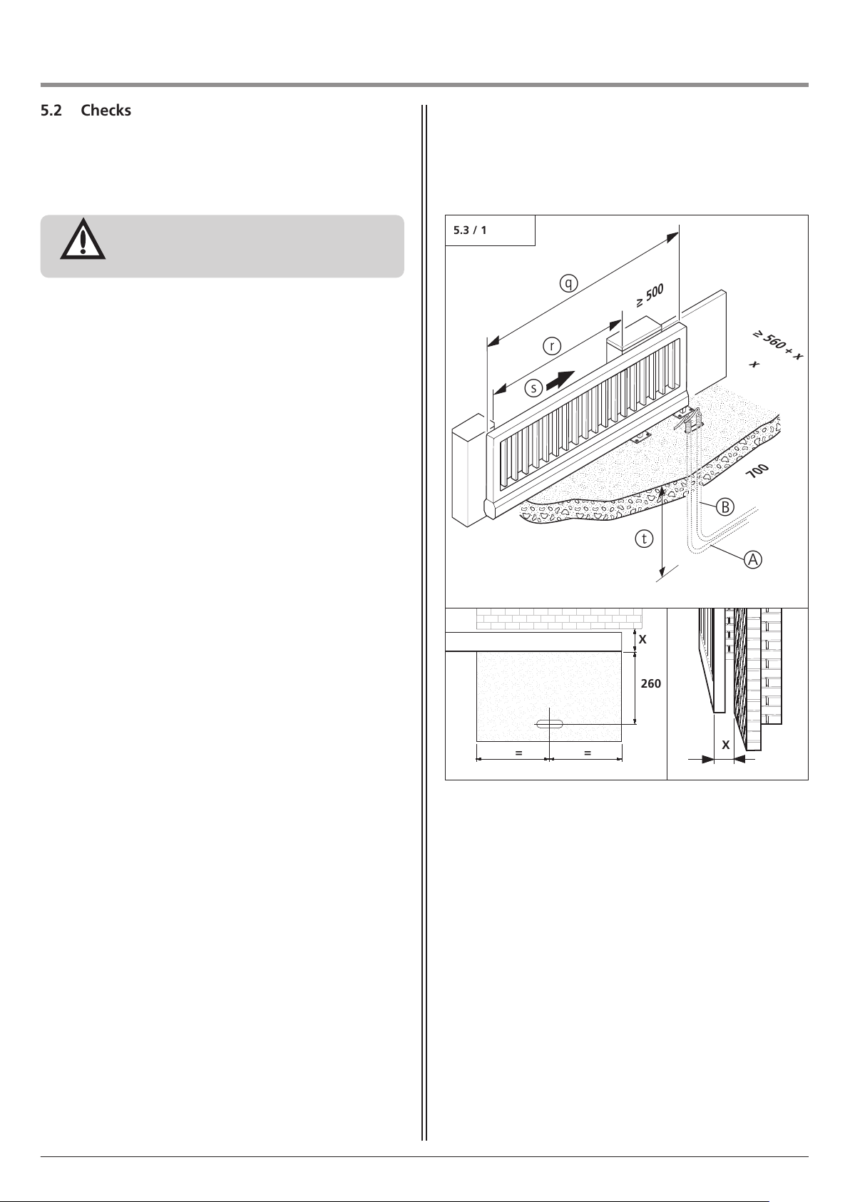
5.3 Gate and foundation layout
5.3 / 1
q
r
s
≥
t
0
0
5
B
x
A
≥
700
5
6
0
+
x
• Check whether the existing foundations are suitable.
• Check the supply cable.
Pay particular attention to the cable exit point where the motor
unit is to be installed.
Gate system
• Ensure that your gate system has an appropriate electricity
supply connection and a facility for disconnecting the mains.
The minimum cross-sectional area of the earth cable is
3 x 1.5 mm
• Ensure that all cables are suitable for outdoor use (UV resistant
and cold resistant).
• To stop the gate in automatic closing, take measures to
safeguard any crushing or shearing zones.
• Install both OPEN and CLOSED gate positions with a mechanical
door limit stop. Choose the position in such a manner that the
closing edge in the OPEN position and the CLOSED position will
not be pushed in or activated.
• Check that the gate to be operated fulfils the following
conditions:
- The travel path of the gate must be horizontal, i.e. on no
account sloping.
- When closed, the gate should extend at least 500 mm further
than the clear width on the installation side.
- The gate must have a mechanical gate stop for both
directions.
- The closing edges must be fitted with a flexible gate seal.
- The gate itself must be straight, so that the distance between
the motor unit and the gate never changes.
Manual for installation and operation, Dynamic 736, 741 FU GB (#116119) 21
2
.
A Empty conduit for control cable
B Empty conduit for electricity supply cable
q Gate width
r Clear width
s Opening direction
t Below depth of frost penetration
x Gate thickness + distance from structure
=
=
X
260
X
Page 22
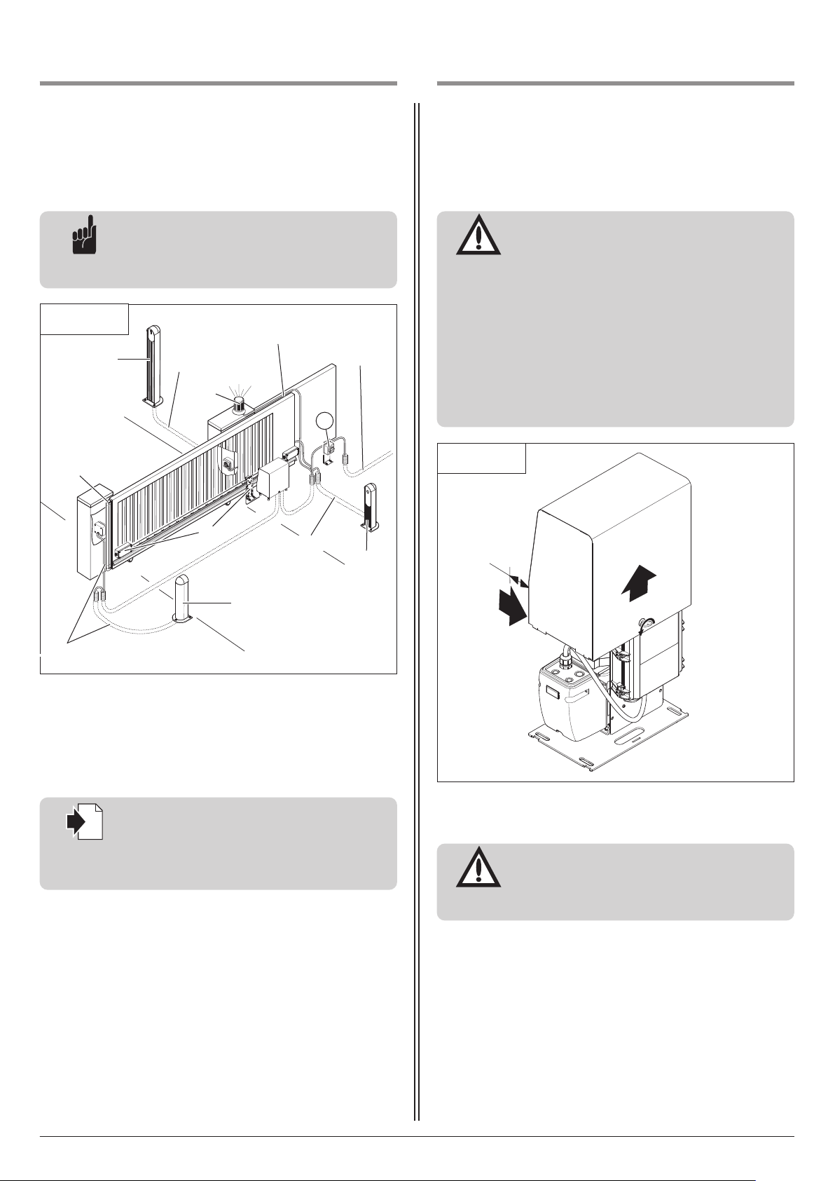
i
5. Preparation for mounting
6. Installation
5.4 Cabling layout
Advice:
This is just an example of a cabling layout; the
layout can vary according to the type of gate
and the associated equipment.
5.4 / 1
2
4
3 x 1.5 mm
x 0.4 mm
2
3
6.1 Installing the motor unit
Attention!
To install the motor unit correctly, the following
points must be assured:
- The motor unit console must be aligned to
face the gate, so that the spur gear can mesh
with the toothed rack whatever the position
2
2
3 x 1.5 mm
230 V AC /
400 V
2
5
6.1 / 1
of the gate.
- The wall plugs for the floor console must be
t least 150 mm from the edge of the
a
foundations.
- After completing installation and commissioning, all the covers must be reattached to the
motor unit.
1
2 x 0.4 mm
6
2 x 0.4 mm
1 Signal transmission system
2 Key switch / Special 750
3 Signal light
4 Closing edge safety device (CESD)
5 Mains isolator switch (mains disconnection facility)
6 Photocell
2
Reference:
For the installation and cabling of the gate sensors, control elements and safety equipment,
the relevant installation instructions must be
observed.
2
6
• Remove the motor unit cover.
~
5
Attention!
To install the motor unit correctly, it must be
mounted at the mid point between the carrier
roller assemblies if the gates are cantilevered.
22 Manual for installation and operation, Dynamic 736, 741 FU GB (#116119)
Page 23
6. Installation
a
a
a
a
a
a
a
a
a
a
a
a
aaa
a
a
a
a
a
a
a
a
a
a
a
aa
a
a
a
a
a
a
a
a
a
a
aa
a
a
a
a
a
a
a
a
a
a
aaa
a
a
a
a
a
a
a
a
a
a
a
aaa
a
a
a
a
a
a
aa
a
aa
a
a
a
a
a
a
a
a
a
a
a
aa
a
a
a
a
a
i
i
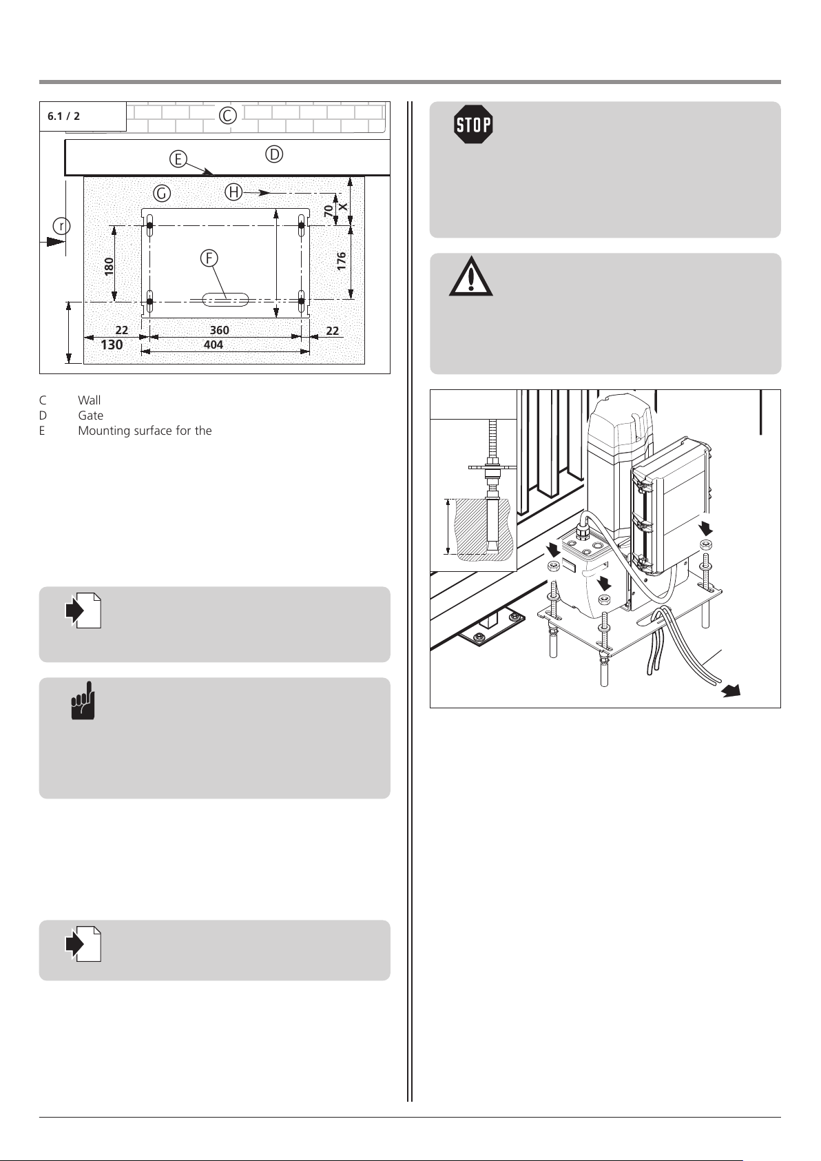
6.1 / 2
E
G
r
180
22
130
C Wall
D Gate
E Mounting surface for the toothed rack
F Empty conduit for power supply cable / control cable
G Foundations
H Front edge of the existing toothed rack
r Clear width
F
404
360
C
H
D
22
X
70
176
6.1 / 3
Caution!
Danger of electric shock:
Before commencing cabling works it is very
important to disconnect the operator system
from the electricity supply. Ensure that the electricity supply remains disconnected for the
uration of the cabling works (e.g. prevent
d
reconnection).
Attention!
- In order to install the motor unit properly, the
foundations must be cured before the motor
unit can be screwed to the floor console.
- In order to guarantee the protection category
f the control, the cables must be passed
o
through the correct screw connection insert.
• Calculate the distance from the mounting surface for the
toothed rack (E) to the motor unit, taking into account
dimension X.
Special 475: X = 100
Reference:
When determining the mounting surface for
the toothed rack, the information given in
Section 6.2.2 must be observed.
Advice:
- When using an existing toothed rack, the
correct dimension is 27 mm from the first
screw to the front edge of the toothed rack.
- The floor console can either be screwed to the
foundations or set into the foundations as
required.
• Before installing the motor unit, check whether the possible
height adjustment of the motor unit (approx. 50 mm) is
sufficient for the situation on site, or if the motor unit needs to
be raised on a backplate.
• Align the floor console, with the motor unit parallel to the gate.
95 – 100
J
• Drill the holes for the wall plugs as shown in the drill pattern
provided.
• Insert the wall plugs.
• Feed the control cable (J) into the motor unit.
• Align the motor unit.
• Screw down the motor unit.
Reference:
The height adjustment of the motor unit is
Manual for installation and operation, Dynamic 736, 741 FU GB (#116119) 23
described in Section 6.3.
Page 24

i
6. Installation
i
.2 Mounting the toothed rack
6
6.2.1 General
Attention!
To install the rack correctly, the following must
be ensured:
- The motor unit has been mounted.
- The motor unit is unlocked (released).
Reference:
For gates with an existing toothed
rack, please skip to Section 6.3.
- Section 6.4 describes how to release the
motor unit.
Minimum length of toothed rack
The minimum length of the toothed rack is equal to the
movement stroke of the gate between the gate OPEN and gate
CLOSED positions + 180 mm.
Maximum length of toothed rack
The maximum length of the toothed rack is equal to the width of
the gate.
6.2.2 Determining the installation height
Attention!
To ensure trouble-free movement of the gate,
the following points must be assured:
- The screws (A) should not obstruct the
operation of the gate (e.g. by extending into
the path of the gate rollers (B)).
- The spur gear (C) should not rest against the
gate.
The spur gear (C) should not be at its lowest
possible position (it must be possible to lower
the spur gear by 1 to 2 mm after the toothed
rack assembly has been installed).
6.2.2 / 1
D
A
B
C
190 – 200
• Determine the installation height of the toothed rack on the
gate.
• Adjust the height of the spur gear accordingly.
Reference:
The height adjustment for the motor unit is
described in Section 6.3.
Advice:
The toothed rack can be adapted to fit the gate
by means of a backplate (D).
24 Manual for installation and operation, Dynamic 736, 741 FU GB (#116119)
Page 25
i
6. Installation
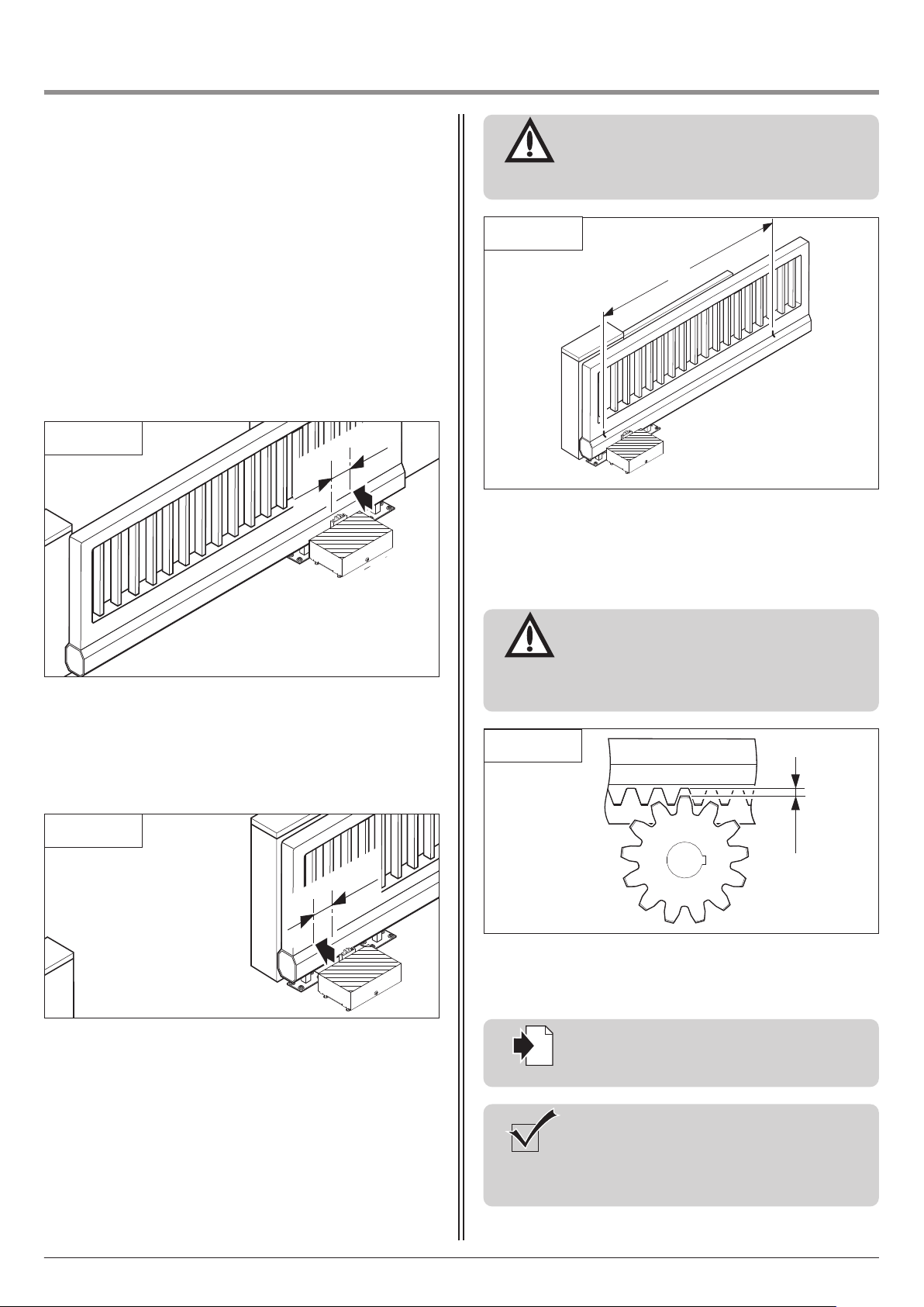
6.2.3 Determining the installation position and the length
of the toothed rack
Maximum length of toothed rack
If a toothed rack is to be installed across the entire width of the
gate, then the installation position does not have to be deter-
ined. The length and installation position of the toothed rack
m
correspond to the gate width.
Minimum length of toothed rack
The minimum length of toothed rack must be determined at the
gate.
Attention!
To ensure trouble-free operation, the toothed
rack must at least extend across the area (E)
between the markings.
6.2.3 / 3
E
6.2.3 / 1
9
• Move the gate to the CLOSED position.
• Make a mark on the gate:
90 mm from the centre of the spur gear in the direction of
opening.
6.2.3 / 2
90
0
6.2.4 Adjust the motor unit
Attention!
To ensure that the gate runs smoothly, it is
important that a vertical gap of 1 to 2 mm is
maintained between the toothed rack and the
spur gear.
6.2.4 / 1
1 – 2
The height of the spur gear must therefore be readjusted.
• Lower the spur gear by 1 to 2 mm.
Reference:
• Move the gate to the OPEN position.
• Make a mark on the gate:
90 mm from the centre of the spur gear in the direction of
closing.
Manual for installation and operation, Dynamic 736, 741 FU GB (#116119) 25
Section 6.3 describes how to adjust the height
of the motor unit.
Check:
To check that the spur gear engages the
toothed rack along its entire length, the gate
must be pushed once to the OPEN position and
back to the CLOSED position.
Page 26
6. Installation
6.3 Adjusting the height of the motor unit
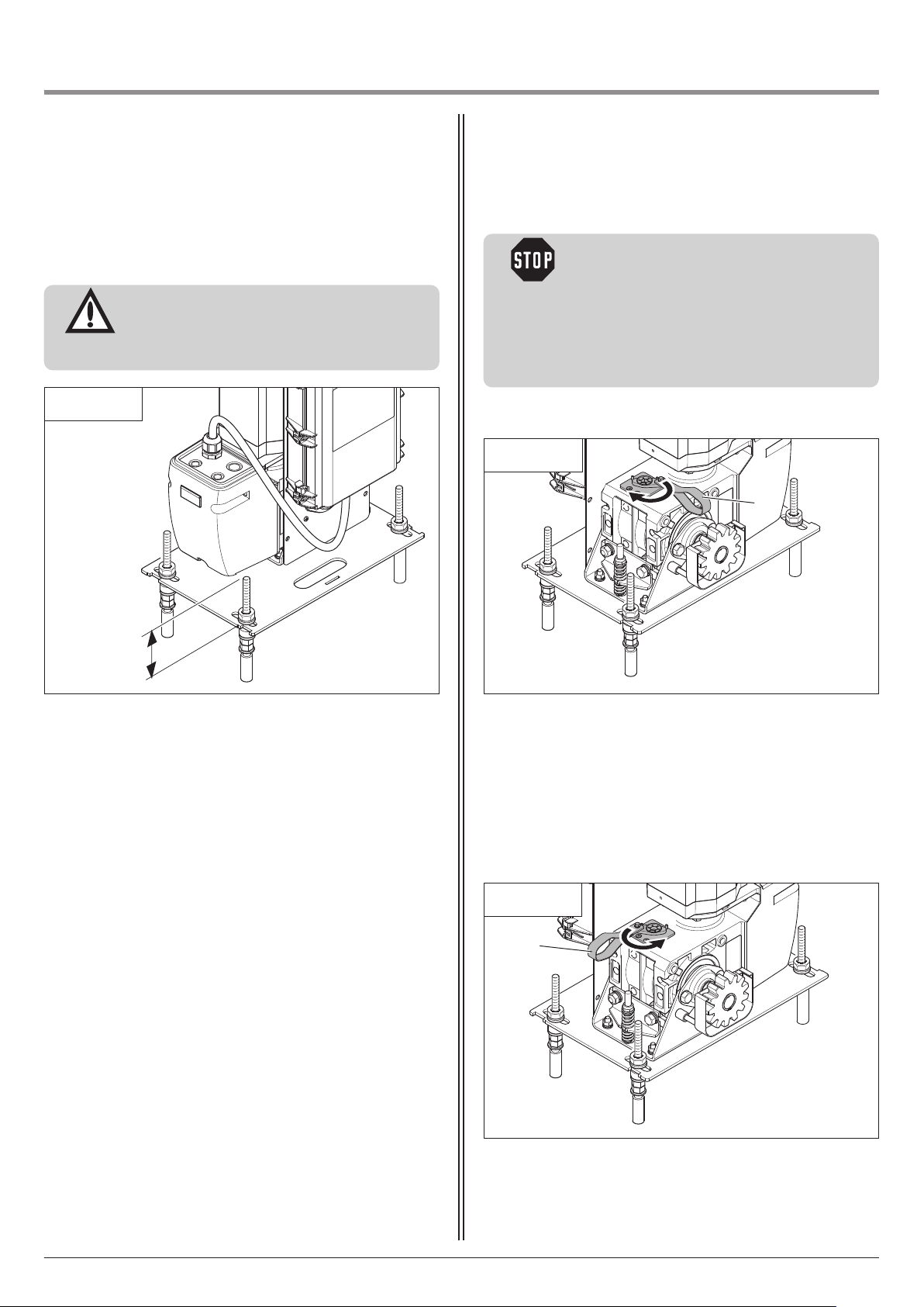
It is possible to adjust the height of the motor unit.
Attention!
To ensure that the gate runs smoothly, it is
important that the gear wheel engages with
the toothed rack along its entire length.
6.3 / 1
6.4 Release mechanism
Caution!
To avoid injury:
- Emergency operation may only be carried out
from a safe standing position.
- Ensure that no one is near the danger area of
the gate during operation.
- Only trained personnel may operate the
system.
Unlocking the motor unit
6.4 / 1
A
< 50
• Loosen the screws.
• Adjust the motor unit to the appropriate height.
• Fasten the screws tight.
• Pull down on the release cable handle (A).
Moving the gate
The gate can be moved manually towards the OPEN or CLOSED
position.
Locking the motor unit
6.4 / 2
A
• Pull down on the release cable handle (A).
26 Manual for installation and operation, Dynamic 736, 741 FU GB (#116119)
Page 27

i
6. Installation
i
7. Initial operation
6.5 Connection of control elements
Reference:
For installation and wiring of the control unit,
the relevant instructions must be followed.
Reference:
Instructions for initial operation and programming of the unit are given in the instruction
manual for the control unit.
Manual for installation and operation, Dynamic 736, 741 FU GB (#116119) 27
Page 28
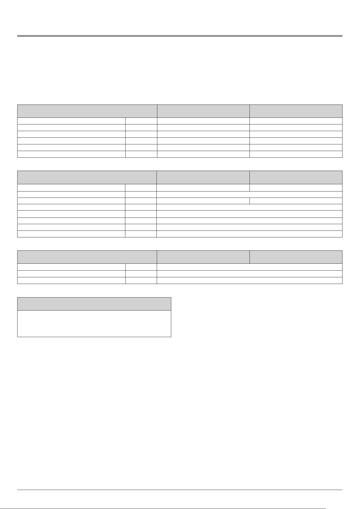
8. Attachment
8.1 Technical data for Dynamic 736, 741 FU
Mechanical data / Type
Driving torque Nm 80 100
Nominal RPM min
Max. revolutions, driven shaft 76 76
Emergency operation Release mechanism Release mechanism
Sleeve shaft diameter mm 25,4 25,4
Gate travel speed at 50 Hz mm/sec. 180 120
Electrical data / Type
Mains voltage V Y 3N~ 400 1N~ 230
Rated frequency Hz 50
Input current A Y 1.9 3.3
Motor power kW 0,55
Motor duty cycle (ED) % S 3 - 60
Power supply for external elements V 24 / 500 mA
Protection category IP 65
Protection class I
Physical and ambient data / Type
Dimensions mm 404 x 498 x 306
Weight kg 27.0
Temperature range C˚ -20 to +60
-1
Dynamic 736
80/45
45 30
Dynamic 736
80/45
Dynamic 736
80/45
Dynamic 741 FU
100/30
Dynamic 741 FU
100/30
Dynamic 741 FU
100/30
Application
Can be universally used for gates up to 18 m wide
and
- max. 1,100 kg weight (Dynamic 736)
- max. 1,300 kg weight (Dynamic 741 FU)
28 Manual for installation and operation, Dynamic 736, 741 FU GB (#116119)
Page 29
8. Attachment
8.2 Declaration for the incorporation of a
partly completed machine
(Declaration of Incorporation in line with EC Machinery Directive
2006/42/EC in accordance with Annex II, Part 1 B)
Manufacturer:
Marantec Antriebs und Steuerungstechnik GmbH & Co. KG,
Remser Brook 11, 33428 Marienfeld, Germany
The partly completed machine (product):
Sliding gate operator Dynamic 736, 741 FU
has been developed, designed and manufactured in accordance with
the:
– EU Machinery Directive 2006/42/EC
– EU RoHS Directive 2011/65/EU
– EU Low Voltage Directive 2014/35/EU
– EU Electromagnetic Compatibility Directive 2014/30/EU
– Radio Equipment Directive (RED) 2014/53/EU
Applied and referenced standards and specifications:
– EN ISO 13849-1, PL “c”, Cat. 2
Safety of machinery - Safety-related parts of control systems - Part
1: General principles for design
– EN 60335-2-103
Household and similar electrical appliances – Safety – Part 2-103:
Particular requirements for drives for gates, doors and windows.
– EN 61000-6-3/2
Electromagnetic compatibility – Emitted interference and immunity
Scope of these installation and operating instructions:
Date of manufacture 01.10.2016 - 30.09.2017
1 February 2016 M. Hörmann
Management
The following requirements of EC Directive 2006/42/EC were complied with:
General principles, No. 1.1.2, 1.1.3, 1.1.5, 1.1.6, 1.2.1, 1.2.2, 1.2.3,
1.2.6, 1.3.1, 1.3.4, 1.3.7, 1.3.8, 1.3.9, 1.4.1, 1.4.3, 1.5.1, 1.5.4,
1.5.6, 1.5.8, 1.5.14, 1.7
Furthermore, we declare that the special technical documentation for
this partly completed machine was prepared in accordance with
Annex VII Part B and we undertake to supply these documents, in
electronic form, to the national authorities in response to a duly reasoned request.
This partly completed machine is intended only for installation in a
door system, in order to create a complete machine pursuant to
Machinery Directive 2006/42/EC. The door system may not be set in
operation until it has been ascertained that the complete system
complies with the requirements of the above-mentioned EC directives.
This declaration shall no longer be valid if changes are made to the
product without our authorisation.
Authorised agent for the preparation of the technical documentation:
Marantec Antriebs- und Steuerungstechnik GmbH & Co. KG, Remser
Brook 11 · 33428 Marienfeld · Germany
Fon +49 (5247) 705-0
Manual for installation and operation, Dynamic 736, 741 FU GB (#116119) 29
Page 30

30 Manual for installation and operation, Dynamic 736, 741 FU GB (#116119)
Page 31

Manual for installation and operation, Dynamic 736, 741 FU GB (#116119) 31
Page 32

Deutsch Originalanleitung, urheberrechtlich geschützt.
achdruck, auch auszugsweise, nur mit unserer Genehmigung.
N
Änderungen, die dem technischen Fortschritt dienen, vorbehalten.
English Original instructions, Copyright.
No part of this manual may be reproduced without our prior consent.
Subject to changes which are in the interest of technical improvements.
Stand: 10.2016
#116119
1 - D/GB 360418 - M - 0.5 - 0614
 Loading...