

Page 1
Comfort 515 / Control x.51
Operator system for Hinged Gates
GB
Manual for installation and operation
Page 2
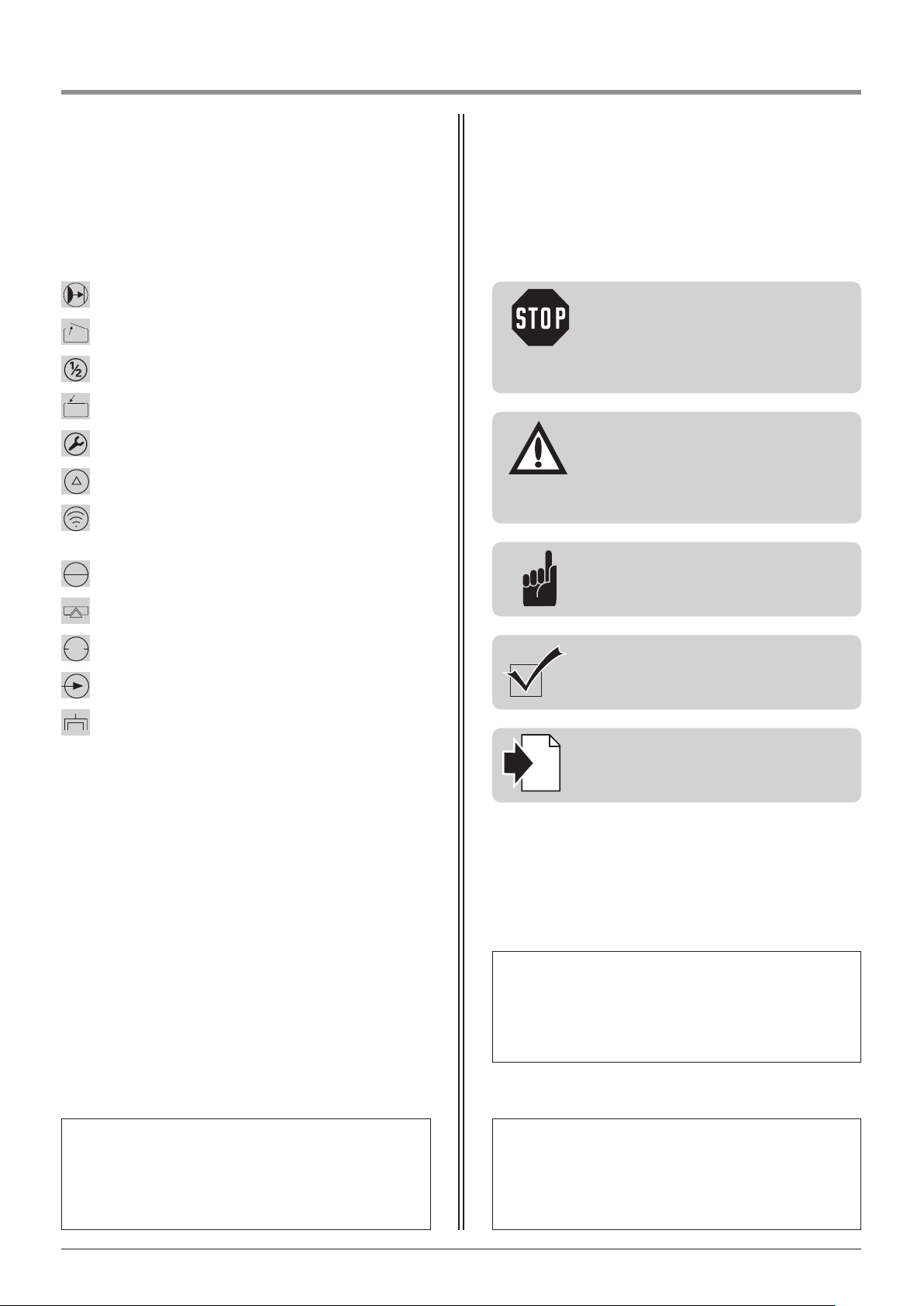
1. Meaning of symbols
Caution!
Danger of personal injury!
The following safety advice must be
observed at all times in order to avoid
personal injury!
Attention!
Danger of material damage!
The following safety advice must be
observed at all times in order to avoid
material damage!
Advice / Tip
Check
Reference
i
Photocell or closing edge safety device (CESD)
Gate position OPEN
Has no function
Gate position CLOSED
Has no function
Has no function
Impulse
(remote control, external control elements)
Operation
Closing edge safety device
STOP
External control elements
Modular antenna
Controls and motor unit symbols Advice
Type plate, motor unit 2 (only double wing)
Type: ________________________________________________
Art. No.: _____________________________________________
Product-No.: __________________________________________
Type plate, motor unit 1
Type: ________________________________________________
Art. No.: _____________________________________________
Product-No.: __________________________________________
Type plate, control unit
Type: ________________________________________________
Art. No.: _____________________________________________
Product-No.: __________________________________________
2 Manual for installation and operation, Comfort 515 GB (#87458)
Page 3

2. Table of contents
1. Meaning of symbols . . . . . . . . . . . . . . . . . . . . . . . . . . . . . . . . . . . . . . . . . . . . . . . . . . . . . . . . . . . . . . . . . . . .2
2. Table of contents . . . . . . . . . . . . . . . . . . . . . . . . . . . . . . . . . . . . . . . . . . . . . . . . . . . . . . . . . . . . . . . . . . . . . . .3
3. General safety advice . . . . . . . . . . . . . . . . . . . . . . . . . . . . . . . . . . . . . . . . . . . . . . . . . . . . . . . . . . . . . . . . . . .4
4. Product overview . . . . . . . . . . . . . . . . . . . . . . . . . . . . . . . . . . . . . . . . . . . . . . . . . . . . . . . . . . . . . . . . . . . . . .6
4.1 Comfort 515 supply package . . . . . . . . . . . . . . . . . . . . . . . . . . . . . . . . . . . . . . . . . . . . . . . . . . . . . . . . . .6
4.2 Dimensions . . . . . . . . . . . . . . . . . . . . . . . . . . . . . . . . . . . . . . . . . . . . . . . . . . . . . . . . . . . . . . . . . . . . . . .8
4.3 Gate variations . . . . . . . . . . . . . . . . . . . . . . . . . . . . . . . . . . . . . . . . . . . . . . . . . . . . . . . . . . . . . . . . . . . . .9
5. Preparation for mounting . . . . . . . . . . . . . . . . . . . . . . . . . . . . . . . . . . . . . . . . . . . . . . . . . . . . . . . . . . . . . .10
5.1 General notes . . . . . . . . . . . . . . . . . . . . . . . . . . . . . . . . . . . . . . . . . . . . . . . . . . . . . . . . . . . . . . . . . . . .10
5.2 Checks . . . . . . . . . . . . . . . . . . . . . . . . . . . . . . . . . . . . . . . . . . . . . . . . . . . . . . . . . . . . . . . . . . . . . . . . . .10
5.3 Cabling layout . . . . . . . . . . . . . . . . . . . . . . . . . . . . . . . . . . . . . . . . . . . . . . . . . . . . . . . . . . . . . . . . . . . .11
6. Installation . . . . . . . . . . . . . . . . . . . . . . . . . . . . . . . . . . . . . . . . . . . . . . . . . . . . . . . . . . . . . . . . . . . . . . . . . . .12
6.1 Mounting conditions . . . . . . . . . . . . . . . . . . . . . . . . . . . . . . . . . . . . . . . . . . . . . . . . . . . . . . . . . . . . . . .12
6.2 Prepare installation dimensions . . . . . . . . . . . . . . . . . . . . . . . . . . . . . . . . . . . . . . . . . . . . . . . . . . . . . . .13
6.3 Fixing the post bracket . . . . . . . . . . . . . . . . . . . . . . . . . . . . . . . . . . . . . . . . . . . . . . . . . . . . . . . . . . . . . .17
6.4 Fixing the motor unit to the post bracket . . . . . . . . . . . . . . . . . . . . . . . . . . . . . . . . . . . . . . . . . . . . . . . .18
6.5 Fixing the control unit . . . . . . . . . . . . . . . . . . . . . . . . . . . . . . . . . . . . . . . . . . . . . . . . . . . . . . . . . . . . . .18
6.6 Connection of control elements . . . . . . . . . . . . . . . . . . . . . . . . . . . . . . . . . . . . . . . . . . . . . . . . . . . . . .19
6.7 Connecting the operator to the controls . . . . . . . . . . . . . . . . . . . . . . . . . . . . . . . . . . . . . . . . . . . . . . . .24
6.8 Connection of the mains cable . . . . . . . . . . . . . . . . . . . . . . . . . . . . . . . . . . . . . . . . . . . . . . . . . . . . . . .26
6.9 Setting the CLOSED and OPEN gate positions . . . . . . . . . . . . . . . . . . . . . . . . . . . . . . . . . . . . . . . . . . . .27
6.10 Mounting the gate bracket . . . . . . . . . . . . . . . . . . . . . . . . . . . . . . . . . . . . . . . . . . . . . . . . . . . . . . . . . .29
6.11 Release . . . . . . . . . . . . . . . . . . . . . . . . . . . . . . . . . . . . . . . . . . . . . . . . . . . . . . . . . . . . . . . . . . . . . . . . .29
7. Hand transmitter . . . . . . . . . . . . . . . . . . . . . . . . . . . . . . . . . . . . . . . . . . . . . . . . . . . . . . . . . . . . . . . . . . . . . .30
7.1 Operation and accessories . . . . . . . . . . . . . . . . . . . . . . . . . . . . . . . . . . . . . . . . . . . . . . . . . . . . . . . . . . .30
7.2 Hand transmitter coding . . . . . . . . . . . . . . . . . . . . . . . . . . . . . . . . . . . . . . . . . . . . . . . . . . . . . . . . . . . .31
8. Initial operation . . . . . . . . . . . . . . . . . . . . . . . . . . . . . . . . . . . . . . . . . . . . . . . . . . . . . . . . . . . . . . . . . . . . . . .32
8.1 Connecting the modular antenna . . . . . . . . . . . . . . . . . . . . . . . . . . . . . . . . . . . . . . . . . . . . . . . . . . . . .32
8.2 Overview of the control unit . . . . . . . . . . . . . . . . . . . . . . . . . . . . . . . . . . . . . . . . . . . . . . . . . . . . . . . . .33
8.3 Overview of the display functions . . . . . . . . . . . . . . . . . . . . . . . . . . . . . . . . . . . . . . . . . . . . . . . . . . . . .33
8.4 Express programming . . . . . . . . . . . . . . . . . . . . . . . . . . . . . . . . . . . . . . . . . . . . . . . . . . . . . . . . . . . . . .34
8.5 Function test . . . . . . . . . . . . . . . . . . . . . . . . . . . . . . . . . . . . . . . . . . . . . . . . . . . . . . . . . . . . . . . . . . . . .36
9. Extended operator functions . . . . . . . . . . . . . . . . . . . . . . . . . . . . . . . . . . . . . . . . . . . . . . . . . . . . . . . . . . . .37
9.1 General notes on extended operator functions . . . . . . . . . . . . . . . . . . . . . . . . . . . . . . . . . . . . . . . . . . .37
9.2 Programming structure for extended operator functions (Example for Level 2, Menu 2) . . . . . . . . . . . . .38
9.3 General overview of the programmable functions . . . . . . . . . . . . . . . . . . . . . . . . . . . . . . . . . . . . . . . . .39
9.4 Functions overview for the levels . . . . . . . . . . . . . . . . . . . . . . . . . . . . . . . . . . . . . . . . . . . . . . . . . . . . . .40
10. Messages . . . . . . . . . . . . . . . . . . . . . . . . . . . . . . . . . . . . . . . . . . . . . . . . . . . . . . . . . . . . . . . . . . . . . . . . . . . .49
10.1 Status messages . . . . . . . . . . . . . . . . . . . . . . . . . . . . . . . . . . . . . . . . . . . . . . . . . . . . . . . . . . . . . . . . . .49
10.2 Fault messages . . . . . . . . . . . . . . . . . . . . . . . . . . . . . . . . . . . . . . . . . . . . . . . . . . . . . . . . . . . . . . . . . . . .49
10.3 Rectifying faults . . . . . . . . . . . . . . . . . . . . . . . . . . . . . . . . . . . . . . . . . . . . . . . . . . . . . . . . . . . . . . . . . . .51
11. Attachment . . . . . . . . . . . . . . . . . . . . . . . . . . . . . . . . . . . . . . . . . . . . . . . . . . . . . . . . . . . . . . . . . . . . . . . . . .54
11.1 Connection diagram Comfort 515 . . . . . . . . . . . . . . . . . . . . . . . . . . . . . . . . . . . . . . . . . . . . . . . . . . . . .54
11.2 Technical Data for Comfort 515 . . . . . . . . . . . . . . . . . . . . . . . . . . . . . . . . . . . . . . . . . . . . . . . . . . . . . . .55
11.3 Manufacturer’s Declaration . . . . . . . . . . . . . . . . . . . . . . . . . . . . . . . . . . . . . . . . . . . . . . . . . . . . . . . . . .56
11.4 EC Declaration of Conformity . . . . . . . . . . . . . . . . . . . . . . . . . . . . . . . . . . . . . . . . . . . . . . . . . . . . . . . .56
Manual for installation and operation, Comfort 515 GB (#87458) 3
Page 4

Please read carefully!
Target group
This operator system may only be installed, connected and put into operation by qualified and trained professionals!
Qualified and trained specialist personnel are persons
- who have knowledge of the general and special safety regulations,
- who have knowledge of the relevant electro-technical regulations,
- with training in the use and maintenance of suitable safety equipment,
- who are sufficiently trained and supervised by qualified electricians,
- who are able to recognise the particular hazards involved when working with electricity,
- with knowledge regarding applications of the EN 12635 standard (installation and usage requirements).
Warranty
For an operations and safety warranty, the advice in this instruction manual has to be observed. Disregarding these
warnings may lead to personal injury or material damage. If this advice is disregarded, the manufacturer will not be
liable for damages that might occur.
Batteries, fuses and bulbs are excluded from warranty.
To avoid installation errors and damage to the gate and operator system, it is imperative that the installation
instructions are followed. The system may only be used after thoroughly reading the respective mounting and
installation instructions.
The installation and operating instructions are to be given to the gate system user, who must keep them safe.
They contain important advice for operation, checks and maintenance.
This item is produced according to the directives and standards mentioned in the Manufacturer's Declaration and in
the Declaration of Conformity. The product has left the factory in perfect condition with regard to safety.
Power-operated windows, doors and gates must be checked by an expert (and this must be documented) before they
are put into operation and thereafter as required, but at least once a year.
Correct use
The operator system is designed exclusively for opening and closing hinged doors and gates.
Gate requirements
The short version operator system - Comfort 515 is suitable for:
- hinged doors and gates with a gate wing width of 2.5 m and a gate wing weight of 200 kg.
Beside the advice in these instructions, please observe the general safety and accident prevention regulations!
Our sales and supply terms and conditions are effective.
3. General safety advice
4 Manual for installation and operation, Comfort 515 GB (#87458)
Page 5

Information on installing the operator system
• Ensure that the gate is in good mechanical condition.
• Ensure that the gate opens and closes properly.
• Remove all unnecessary components from the gate (e.g. cables, chains, brackets).
• Render any installations inoperable that will no longer be needed after the operator system has been installed.
• Before commencing cabling works it is very important to disconnect the operator system from the electricity supply.
Ensure that the electricity supply remains disconnected throughout the cabling works.
• Adhere to the local protection regulations.
• Lay the electricity supply cables and control cables; these MUST be laid separately. The controls voltage is 24 V DC.
• Install all the impulse transmitters and control devices (e.g. remote control buttons) within sight of the gate and at a
safe distance from the moving parts of the gate. A minimum installation height of 1.5 m must be observed.
• Ensure that no part of the gate extends across public footways or roads when the installation is complete.
Information on commissioning the operator system
After initial operation, the persons responsible for operating the gate system, or their representatives must be
familiarised with the use of the system.
• Make sure that children cannot access the gate control unit.
• Before moving the gate, make sure that there are neither persons nor objects in the operating range of the gate.
• Test all existing emergency command devices.
• Never insert your hands into a running gate or moving parts.
• Pay attention to any parts of the gate system that could cause crushing or shearing damage or accidents.
The EN 13241-1 regulations must be observed.
Information on servicing the operator system
To ensure proper operation, the following items must be checked regularly and repaired if necessary.
Before any works to the gate system are undertaken, the operator system must be disconnected from the mains.
• Check once a month that the operator system stops and reverses in every position when the gate touches an
obstacle. Place an obstacle in the path of the gate to check this.
• Check the settings of the OPEN and CLOSE automatic cut-out function.
• Check all movable parts of the gate and operator system.
• Check the gate system for signs of wear or damage.
• Check whether the gate can be easily moved by hand.
Information on cleaning the operator system
Never use water jets, high pressure cleaners, acids or bases for cleaning.
Please read carefully!
3. General safety advice
Manual for installation and operation, Comfort 515 GB (#87458) 5
Page 6
6 Manual for installation and operation, Comfort 515 GB (#87458)
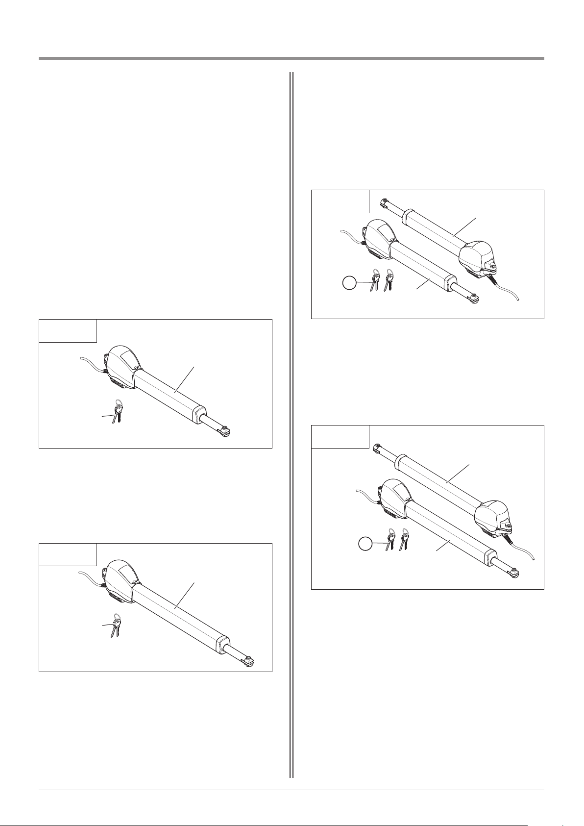
4.1 Comfort 515 supply package
4. Product overview
4.1 / 1
1
2
Single wing gate system
(Short version – Comfort 515)
1 Motor unit with short connection cable (1.5 m)
2 Key (2x)
4.1 / 3
3 Motor unit with short connection cable (1.5 m)
4 Motor unit with long connection cable (8.5 m)
5 Key (4x)
Double wing gate system
(Short version – Comfort 515)
3
4
5
The Comfort 515 standard delivery package comprises:
- motor unit
- controls
- fixing materials for controls
and motor unit
- remote control
The Comfort 515 is available in the following versions,
as required:
4.1 / 2
1
2
Single wing gate system
(Long version – Comfort 515 L)
1 Motor unit with short connection cable (1.5 m)
2 Key (2x)
4.1 / 4
3 Motor unit with short connection cable (1.5 m)
4 Motor unit with long connection cable (8.5 m)
5 Key (4x)
Double wing gate system
(Long version – Comfort 515 L)
3
4
5
Page 7
Manual for installation and operation, Comfort 515 GB (#87458) 7
4. Product overview
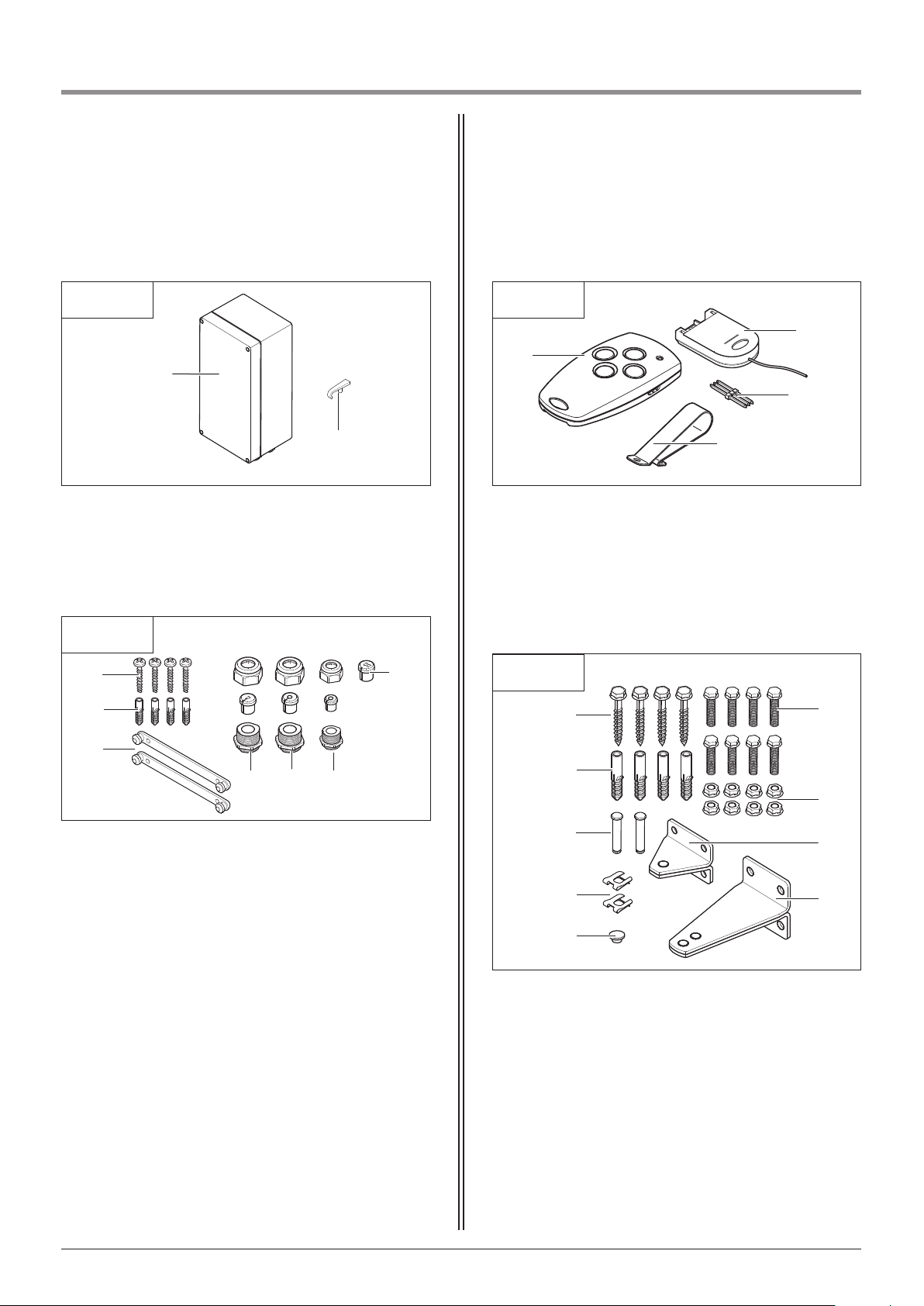
6 Control x.51
7 Handle
8 Screws 3.5 x 32 (4x)
9 Wall plugs S6 (4x)
10 Spacer elements (2x)
11 Screw fixing insert with 2 flat cable openings
12 M20 screw fixing with flat cable insert
13 M20 screw fixing with round cable insert
14 M16 screw fixing with round cable insert
Control unit
Mounting kit for control unit
4.1 / 5
6
7
!#
!¯
!Ø
!”
8
9
4.1 / 6
!£
4.1 / 8
19 Wood screws 8 x 60 (4x)
20 Wall plugs S10 (4x)
21 Bolts 10 x 49 (2x)
22 Locking plates (2x)
23 Cover cap
24 M8 x 25 (8x)
25 Nuts M8 (8x)
26 Gate bracket
27 Post bracket
Single wing gate system installation set
!·
„∏
„¯
„”
„£
„
5
„\
„#
„^
4.1 / 7
15 Hand transmitter
16 Module antenna
17 Transmission plug
18 Sun visor clip
Remote control
!5
!˜
!^
!\
Page 8
8 Manual for installation and operation, Comfort 515 GB (#87458)
4. Product overview
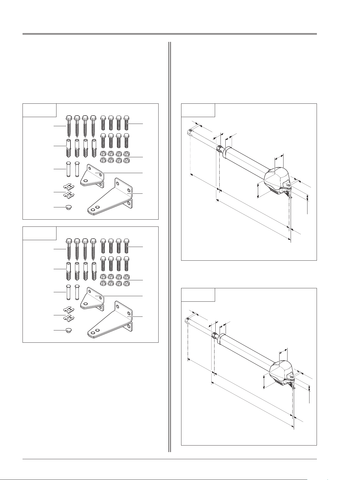
19 Wood screws 8 x 60 (8x)
20 Wall plugs S10 (8x)
21 Bolts 10 x 49 (4x)
22 Locking plates (4x)
23 Cover caps (2x)
24 M8 x 25 (16x)
25 Nuts M8 (16x)
26 Gate brackets (2x)
27 Post brackets (2x)
Double wing gate system installation set
4.1 / 9
!·
„∏
„¯
„”
„£
„5
„\
„#
„^
4.1 / 10
!·
„∏
„¯
„”
„£
„
5
„\
„#
„^
4.2 / 1
4.2 Dimensions
122
39
68
197,5
755
722,4
14,7
ø 10,1
400
ø 10,1
47,2
Short version – Comfort 515
Long version – Comfort 515 L
4.2 / 2
122
39
68
197,5
955
922,4
14,7
ø 10,1
600
ø 10,1
47,2
Page 9
4. Product overview
Manual for installation and operation, Comfort 515 GB (#87458) 9
4.3 / 1
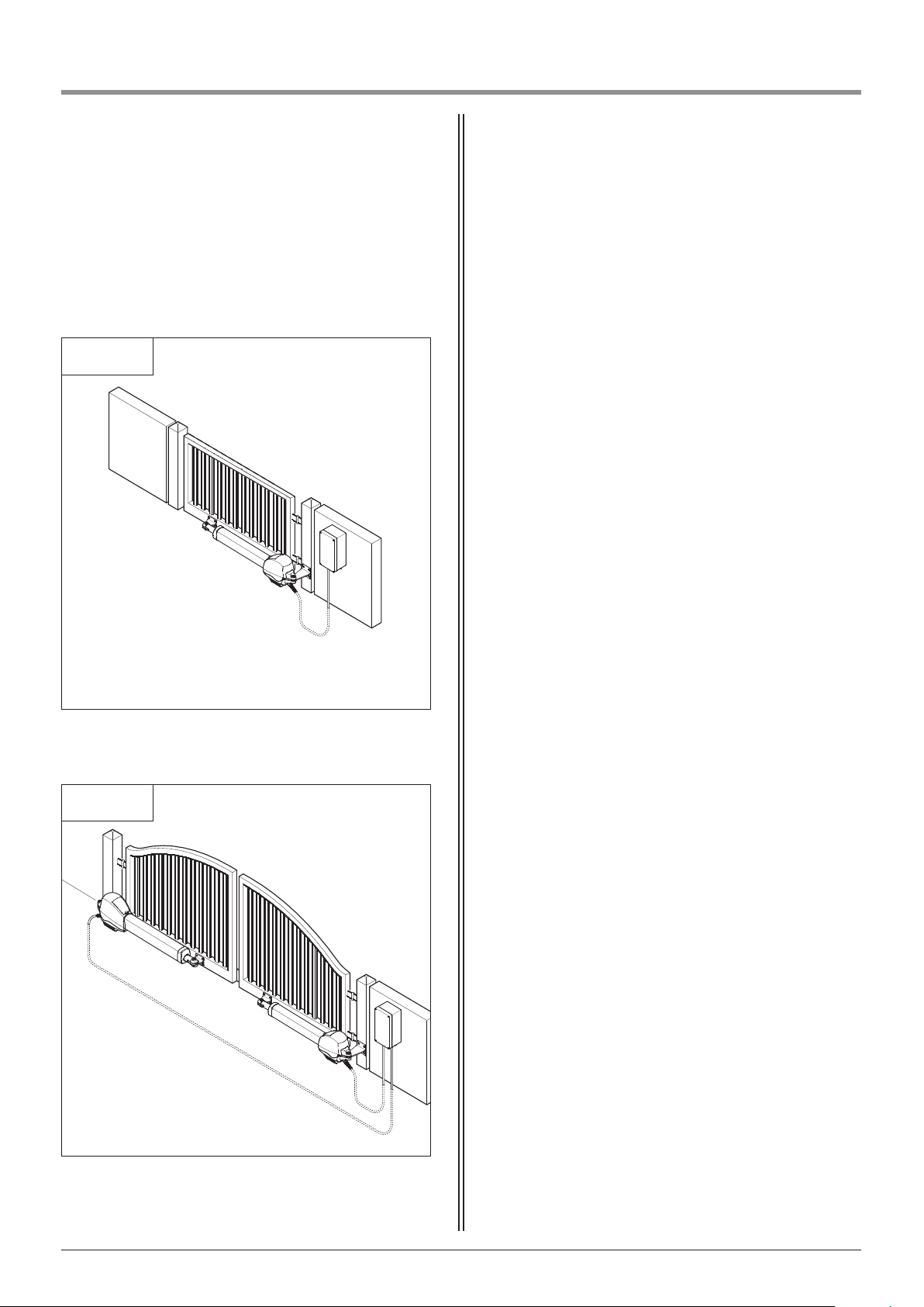
The standard supply package is suitable for
the following types of gate.
Single wing gate system
4.3 / 2
Double wing gate system
4.3 Gate variations
Page 10
5.2 Checks
Attention!
In order to guarantee correct
mounting, carry out the following
checks before installing.
Supply package
• Check the package to ensure that all the parts are
included.
• Check that you have all the additional components
that are necessary for your particular installation
requirements.
Gate system
• Ensure that your gate system has an appropriate
electricity supply connection and a facility
for disconnecting the mains. The minimum
cross-sectional area of the earth cable is
3 x 1.5 mm2.
• Ensure that all cables are suitable for outdoor use
(UV resistant and cold resistant).
• Make sure that your gate system has a stop
plate/block in the closing direction.
• Remove the gate fasteners or latches or render them
inoperative.
• Make sure that the gate is easy to move manually.
• Ensure that the following requirements are met:
Width of gate wing:
- Comfort 515 min. 1 m - max. 2,5 m
- Comfort 515 L min. 1,5 m - max. 3,5 m
Gate height: min. 1.5 m - max. 2.5 m
Weight of gate wing: max. 200 kg
Open area: min. 50%
Gate incline: max. 2%
5. Preparation for mounting
5.1 General notes
The pictures in these instructions are not true-to-scale.
Dimensions are always given in millimetres (mm)!
The motor unit and the controls must be installed on
the inside of the gate system.
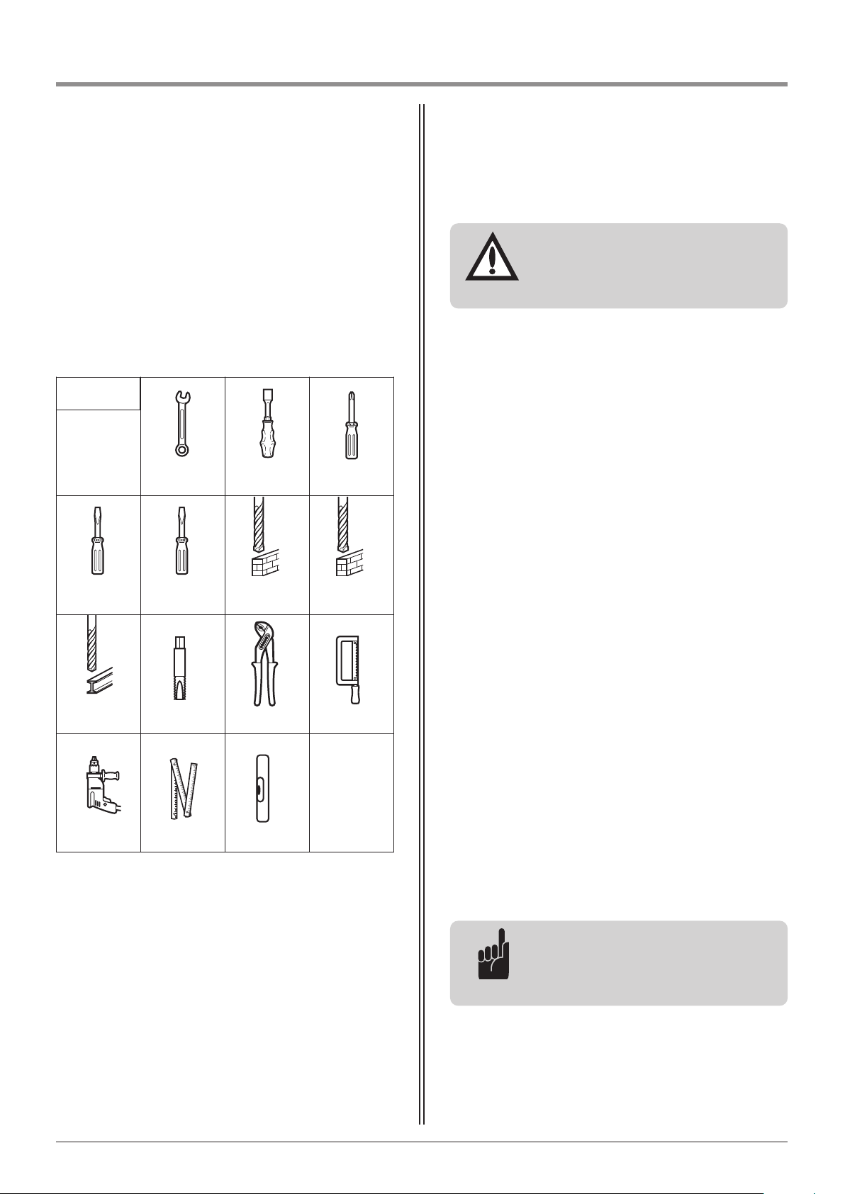
For correct mounting you will need the following
tools:
13
ø 10
ø 6.5
13 2
2
5
M 8
ø 6
5.1 / 1
Advice:
The use of an electric lock is
recommended for a gate wing
wider than 2 m.
10 Manual for installation and operation, Comfort 515 GB (#87458)
Page 11
5. Preparation for mounting
5.3 Cabling layout
5.3 / 1
2 x 0.75 mm
2
2 x 0.75 mm
2
2 x 0.4 mm
2
2 x 0.4 mm
2
2 x 0.4 mm
2
2 x 0.4 mm
2
3 x 1.5 mm
2
230 V / AC
3 x 1.5 mm
2
Advice:
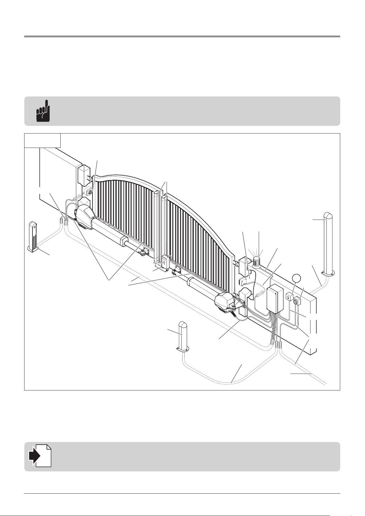
This is just an example of a cabling layout; the layout can vary according to the type of gate and the
associated equipment.
Reference:
For the installation and cabling of the gate sensors, control elements and safety equipment, the relevant
installation instructions must be observed.
i
1 Photocell
2 Photocell
3 Signal light
4 Code button, transponder, ...
5 Key switch
6 Mains isolator switch (mains disconnection facility)
7 Electric lock
8 Stop plate
9 Mains supply cable
10 Cosing edge safety device (CESD)
2
23
4
6
9
7
1
1
8
!¯
5
Manual for installation and operation, Comfort 515 GB (#87458) 11
Page 12
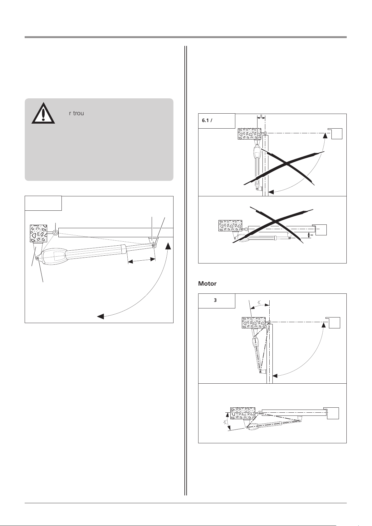
6.1 Mounting conditions
The mounting positions of the gate bracket (C) and
the post bracket (D) are dependent on your gate
configuration.
The positions of the gate bracket (C) and the post
bracket (D) influence the following factors:
- Opening angle (n)
- Utilisation of the movement stroke (m)
- Gate travelling speed
A triangle of forces is formed by the gate pivot (A),
the post bracket pivot (B) and the gate bracket
pivot (I).
6.1 / 1
C
B
D
A
n
m
I
6.1 / 2
Motor unit is parallel to the gate
6.1 / 3
Motor unit is within the triangle of forces
Attention!
For trouble-free operation, choose the
positions of the brackets such that they
meet all following conditions:
- The motor unit must be located in a
triangle of forces and should not be
parallel to the gate at the OPEN and
CLOSED gate positions.
- The length of travel should be as
large as possible.
6. Installation
12 Manual for installation and operation, Comfort 515 GB (#87458)
Page 13
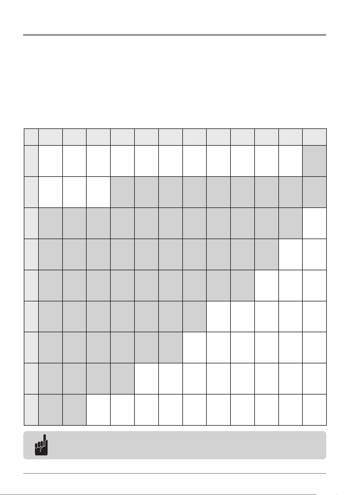
6. Installation
Manual for installation and operation, Comfort 515 GB (#87458) 13
6.2 Prepare installation dimensions
Dimension table for Comfort 515
a = 80 a = 100 a = 120 a = 140 a = 160 a = 180 a = 200 a = 220 a = 240 a = 260 a = 280 a = 300
b =
110
c = 938
c1 = 255
c2 = 50
c = 95°
c = 970
c1 = 285
c2 = 50
d = 105°
c = 997
c1 = 313
c2 = 50
d = 107°
c = 1.040
c1 = 357
c2 = 50
d = 114°
c = 1.084
c1 = 396
c2 = 50
d = 124°
c = 1.118
c1 = 429
c2 = 50
d = 125°
c = 1.122
c1 = 438
c2 = 50
d = 115°
c = 1.122
c1 = 438
c2 = 50
d = 108°
c = 1.118
c1 = 433
c2 = 50
d = 103°
c = 1.122
c1 = 438
c2 = 50
d = 97°
c = 1.120
c1 = 436
c2 = 50
d = 96°
c = 1.122
c1 = 438
c2 = 50
d = 90°
b =
130
c = 955
c1 = 273
c2 = 50
d = 95°
c = 986
c1 = 304
c2 = 50
d = 105°
c = 1.015
c1 = 331
c2 = 50
d = 105°
c = 1.048
c1 = 364
c2 = 50
d = 110°
c = 1.095
c1 = 412
c2 = 50
d = 120°
c = 1.118
c1 = 430
c2 = 50
d = 115°
c = 1.122
c1 = 438
c2 = 50
d = 110°
c = 1.122
c1 = 438
c2 = 50
d = 104°
c = 1.120
c1 = 434
c2 = 50
d = 98°
c = 1.118
c1 = 430
c2 = 50
d = 93°
c = 1.116
c1 = 431
c2 = 50
d = 92°
c = 1.122
c1 = 440
c2 = 50
d = 87°
b =
150
c = 975
c1 = 296
c2 = 50
d = 95°
c = 1.005
c1 = 324
c2 = 50
d = 102°
c = 1.032
c1 = 350
c2 = 50
d = 104°
c = 1.068
c1 = 385
c2 = 50
d = 110°
c = 1.110
c1 = 426
c2 = 50
d = 116°
c = 1.118
c1 = 434
c2 = 50
d = 109°
c = 1.120
c1 = 438
c2 = 50
d = 103°
c = 1.122
c1 = 439
c2 = 50
d = 98°
c = 1.118
c1 = 436
c2 = 50
d = 92°
c = 1.118
c1 = 430
c2 = 50
d = 90°
c = 1.122
c1 = 440
c2 = 50
d = 90°
b =
170
c = 993
c1 = 316
c2 = 50
d = 95°
c = 1.022
c1 = 343
c2 = 50
d = 100°
c = 1.055
c1 = 371
c2 = 50
d = 104°
c = 1.088
c1 = 405
c2 = 50
d = 108°
c = 1.125
c1 = 440
c2 = 50
d = 114°
c = 1.118
c1 = 434
c2 = 50
d = 100°
c = 1.116
c1 = 435
c2 = 50
d = 97°
c = 1.105
c1 = 425
c2 = 50
d = 90°
c = 1.120
c1 = 440
c2 = 50
d = 90°
c = 1.120
c1 = 440
c2 = 50
d = 87°
b =
190
c = 1.020
c1 = 345
c2 = 50
d = 93°
c = 1.045
c1 = 363
c2 = 50
d = 98°
c = 1.072
c1 = 392
c2 = 50
d = 103°
c = 1.105
c1 = 423
c2 = 50
d = 106°
c = 1.120
c1 = 438
c2 = 50
d = 102°
c = 1.122
c1 = 438
c2 = 50
d = 96°
c = 1.120
c1 = 438
c2 = 50
d = 92°
c = 1.116
c1 = 435
c2 = 50
d = 88°
c = 1.120
c1 = 440
c2 = 50
d = 86°
b =
210
c = 1.035
c1 = 356
c2 = 50
d = 92°
c = 1.063
c1 = 383
c2 = 50
d = 97°
c = 1.087
c1 = 407
c2 = 50
d = 100°
c = 1.117
c1 = 437
c2 = 50
d = 101°
c = 1.120
c1 = 440
c2 = 50
d = 95°
c = 1.120
c1 = 440
c2 = 50
d = 90°
c = 1.122
c1 = 440
c2 = 50
d = 87°
b =
230
c = 1.065
c1 = 390
c2 = 50
d = 92°
c = 1.085
c1 = 404
c2 = 50
d = 97°
c = 1.110
c1 = 428
c2 = 50
d = 98°
c = 1.119
c1 = 438
c2 = 50
d = 93°
c = 1.120
c1 = 440
c2 = 50
d = 88°
c = 1.120
c1 = 440
c2 = 50
d = 85°
b =
250
c = 1.085
c1 = 407
c2 = 50
d = 92°
c = 1.102
c1 = 425
c2 = 50
d = 95°
c = 1.117
c1 = 437
c2 = 50
d = 92°
c = 1.120
c1 = 440
c2 = 50
d = 87°
b =
270
c = 1.105
c1 = 433
c2 = 50
d = 91°
c = 1.110
c1 = 437
c2 = 50
d = 90°
Advice:
The preferred dimensions for the Comfort 515 are shaded in grey in the table (for gate wings up to
2.5 m wide and weighing up to 200 kg).
The approximate position of the gate bracket and of the post bracket on the gate can be determined with the help of
the dimension tables.
Page 14
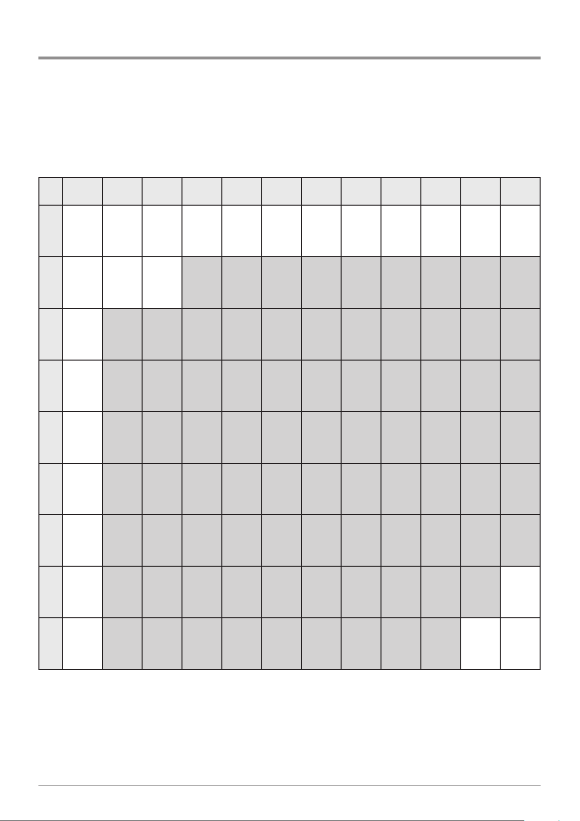
Dimension table for Comfort 515 L
a = 80 a = 100 a = 120 a = 140 a = 160 a = 180 a = 200 a = 220 a = 240 a = 260 a = 280 a = 300
b =
110
c = 1.197
c1 = 312
c2 = 50
d = 105°
c = 1.240
c1 = 356
c2 = 50
d = 112°
c = 1.286
c1 = 397
c2 = 50
d = 123°
c = 1.313
c1 = 428
c2 = 50
d = 125°
c = 1.342
c1 = 458
c2 = 50
d = 125°
c = 1.378
c1 = 492
c2 = 50
d = 125°
c = 1.403
c1 = 518
c2 = 50
d = 125°
c = 1.435
c1 = 550
c2 = 50
d = 125°
c = 1.487
c1 = 603
c2 = 50
d = 130°
c = 1.522
c1 = 640
c2 = 50
d = 135°
b =
130
c = 1.216
c1 = 331
c2 = 50
d = 105°
c = 1.256
c1 = 371
c2 = 50
d = 110°
c = 1.293
c1 = 411
c2 = 50
d = 120°
c = 1.328
c1 = 445
c2 = 50
d = 125°
c = 1.360
c1 = 476
c2 = 50
d = 125°
c = 1.390
c1 = 508
c2 = 50
d = 125°
c = 1.420
c1 = 533
c2 = 50
d = 125°
c = 1.450
c1 = 566
c2 = 50
d = 125°
c = 1.488
c1 = 603
c2 = 50
d = 125°
c = 1.512
c1 = 629
c2 = 50
d = 125°
b =
150
c = 1.200
c1 = 311
c2 = 50
d = 95°
c = 1.234
c1 = 374
c2 = 50
d = 102°
c = 1.268
c1 = 385
c2 = 50
d = 105°
c = 1.310
c1 = 425
c2 = 50
d = 115°
c = 1.344
c1 = 462
c2 = 50
d = 125°
c = 1.367
c1 = 486
c2 = 50
d = 120°
c = 1.395
c1 = 513
c2 = 50
d = 120°
c = 1.420
c1 = 533
c2 = 50
d = 117°
c = 1.457
c1 = 570
c2 = 50
d = 120°
c = 1.485
c1 = 600
c2 = 50
d = 120°
c = 1.510
c1 = 627
c2 = 50
d = 120°
b =
170
c = 1.198
c1 = 310
c2 = 50
d = 90°
c = 1.223
c1 = 335
c2 = 50
d = 95°
c = 1.255
c1 = 368
c2 = 50
d = 102°
c = 1.282
c1 = 395
c2 = 50
d = 102°
c = 1.320
c1 = 431
c2 = 50
d = 108°
c = 1.344
c1 = 459
c2 = 50
d = 110°
c = 1.378
c1 = 496
c2 = 50
d = 115°
c = 1.410
c1 = 525
c2 = 50
d = 115°
c = 1.421
c1 = 534
c2 = 50
d = 110°
c = 1.443
c1 = 558
c2 = 50
d = 110°
c = 1.467
c1 = 583
c2 = 50
d = 110°
c = 1.514
c1 = 628
c2 = 50
d = 115°
b =
190
c = 1.219
c1 = 332
c2 = 50
d = 90°
c = 1.248
c1 = 360
c2 = 50
d = 95°
c = 1.275
c1 = 389
c2 = 50
d = 100°
c = 1.298
c1 = 414
c2 = 50
d = 100°
c = 1.330
c1 = 445
c2 = 50
d = 105°
c = 1.353
c1 = 468
c2 = 50
d = 105°
c = 1.386
c1 = 504
c2 = 50
d = 110°
c = 1.419
c1 = 533
c2 = 50
d = 110°
c = 1.432
c1 = 546
c2 = 50
d = 107°
c = 1.444
c1 = 559
c2 = 50
d = 105°
c = 1.483
c1 = 581
c2 = 50
d = 105°
c = 1.515
c1 = 629
c2 = 50
d = 110°
b =
210
c = 1.239
c1 = 354
c2 = 50
d = 90°
c = 1.268
c1 = 348
c2 = 50
d = 95°
c = 1.298
c1 = 410
c2 = 50
d = 100°
c = 1.320
c1 = 433
c2 = 50
d = 100°
c = 1.342
c1 = 459
c2 = 50
d = 100°
c = 1.370
c1 = 485
c2 = 50
d = 102°
c = 1.395
c1 = 515
c2 = 50
d = 105°
c = 1.415
c1 = 535
c2 = 50
d = 105°
c = 1.435
c1 = 549
c2 = 50
d = 105°
c = 1.435
c1 = 569
c2 = 50
d = 102°
c = 1.476
c1 = 592
c2 = 50
d = 102°
c = 1.514
c1 = 624
c2 = 50
d = 105°
b =
230
c = 1.264
c1 = 378
c2 = 50
d = 90°
c = 1.292
c1 = 402
c2 = 50
d = 95°
c = 1.315
c1 = 432
c2 = 50
d = 100°
c = 1.344
c1 = 460
c2 = 50
d = 100°
c = 1.368
c1 = 484
c2 = 50
d = 100°
c = 1.388
c1 = 505
c2 = 50
d = 100°
c = 1.417
c1 = 530
c2 = 50
d = 102°
c = 1.425
c1 = 543
c2 = 50
d = 102°
c = 1.443
c1 = 559
c2 = 50
d = 102°
c = 1.468
c1 = 584
c2 = 50
d = 100°
c = 1.486
c1 = 604
c2 = 50
d = 100°
c = 1.510
c1 = 626
c2 = 50
d = 100°
b =
250
c = 1.285
c1 = 400
c2 = 50
d = 90°
c = 1.310
c1 = 426
c2 = 50
d = 95°
c = 1.336
c1 = 454
c2 = 50
d = 97°
c = 1.362
c1 = 480
c2 = 50
d = 97°
c = 1.383
c1 = 498
c2 = 50
d = 97°
c = 1.409
c1 = 528
c2 = 50
d = 100°
c = 1.420
c1 = 535
c2 = 50
d = 97°
c = 1.448
c1 = 563
c2 = 50
d = 97°
c = 1.457
c1 = 573
c2 = 50
d = 97°
c = 1.485
c1 = 599
c2 = 50
d = 97°
c = 1.500
c1 = 616
c2 = 50
d = 97°
b =
270
c = 1.310
c1 = 425
c2 = 50
d = 90°
c = 1.340
c1 = 452
c2 = 50
d = 95°
c = 1.358
c1 = 476
c2 = 50
d = 97°
c = 1.380
c1 = 496
c2 = 50
d = 97°
c = 1.403
c1 = 520
c2 = 50
d = 97°
c = 1.430
c1 = 545
c2 = 50
d = 97°
c = 1.444
c1 = 560
c2 = 50
d = 97°
c = 1.470
c1 = 588
c2 = 50
d = 97°
c = 1.474
c1 = 590
c2 = 50
d = 97°
c = 1.490
c1 = 606
c2 = 50
d = 96°
6. Installation
14 Manual for installation and operation, Comfort 515 GB (#87458)
Page 15
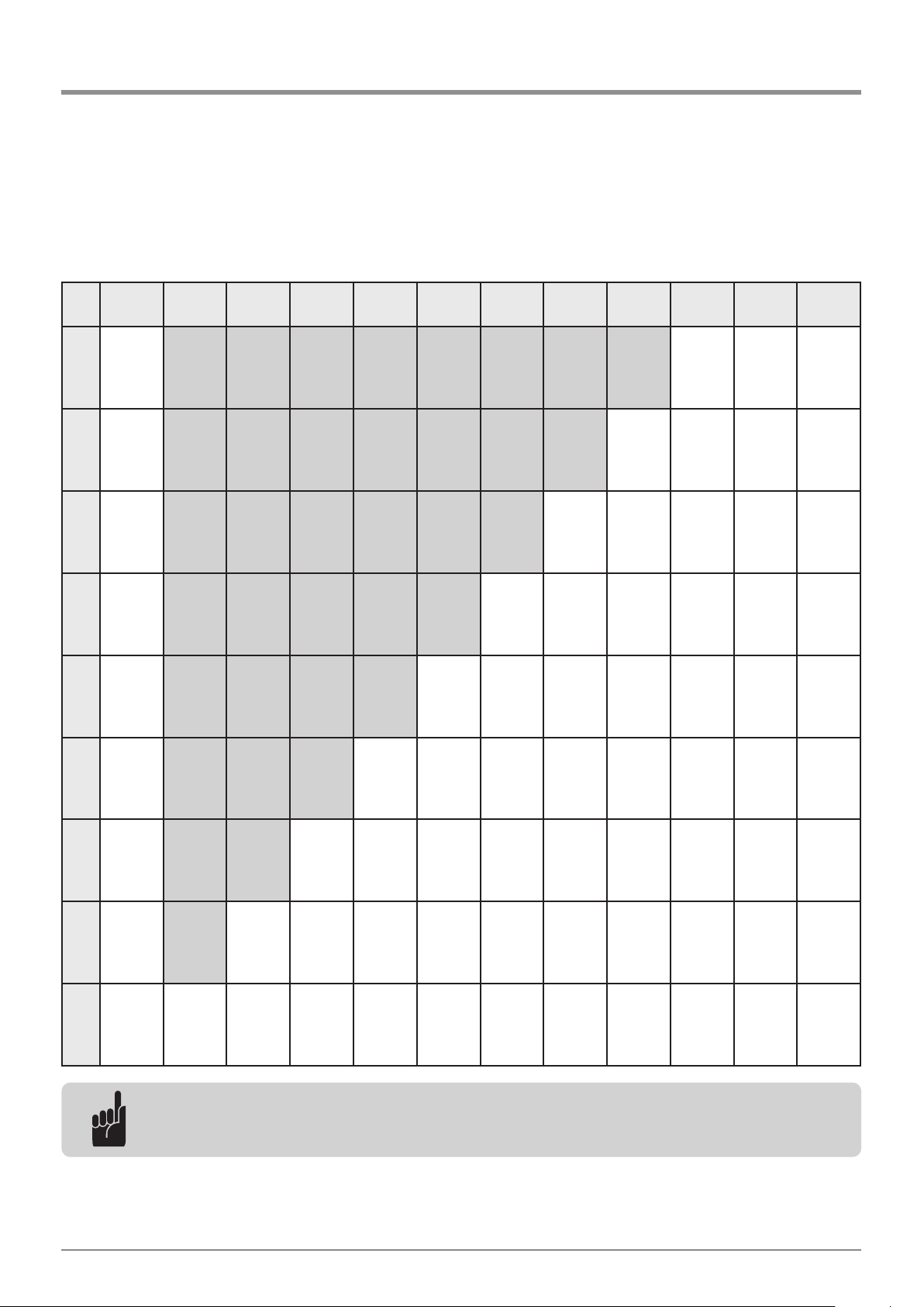
6. Installation
a = 80 a = 100 a = 120 a = 140 a = 160 a = 180 a = 200 a = 220 a = 240 a = 260 a = 280 a = 300
b =
290
c = 1.334
c1 = 448
c2 = 50
d = 90°
c = 1.357
c1 = 475
c2 = 50
d = 95°
c = 1.380
c1 = 498
c2 = 50
d = 97°
c = 1.405
c1 = 524
c2 = 50
d = 95°
c = 1.422
c1 = 538
c2 = 50
d = 95°
c = 1.447
c1 = 563
c2 = 50
d = 95°
c = 1.457
c1 = 573
c2 = 50
d = 95°
c = 1.478
c1 = 595
c2 = 50
d = 95°
c = 1.495
c1 = 610
c2 = 50
d = 95°
b =
310
c = 1.359
c1 = 472
c2 = 50
d = 90°
c = 1.380
c1 = 495
c2 = 50
d = 95°
c = 1.408
c1 = 526
c2 = 50
d = 97°
c = 1.424
c1 = 540
c2 = 50
d = 95°
c = 1.448
c1 = 564
c2 = 50
d = 95°
c = 1.476
c1 = 590
c2 = 50
d = 95°
c = 1.484
c1 = 598
c2 = 50
d = 95°
c = 1.502
c1 = 622
c2 = 50
d = 95°
b =
330
c = 1.383
c1 = 496
c2 = 50
d = 90°
c = 1.403
c1 = 518
c2 = 50
d = 95°
c = 1.433
c1 = 550
c2 = 50
d = 97°
c = 1.451
c1 = 564
c2 = 50
d = 95°
c = 1.470
c1 = 585
c2 = 50
d = 95°
c = 1.490
c1 = 608
c2 = 50
d = 95°
c = 1.508
c1 = 624
c2 = 50
d = 95°
b =
350
c = 1.406
c1 = 522
c2 = 50
d = 90°
c = 1.426
c1 = 543
c2 = 50
d = 95°
c = 1.453
c1 = 571
c2 = 50
d = 97°
c = 1.474
c1 = 588
c2 = 50
d = 95°
c = 1.495
c1 = 611
c2 = 50
d = 95°
c = 1.516
c1 = 634
c2 = 50
d = 95°
b =
370
c = 1.430
c1 = 554
c2 = 50
d = 90°
c = 1.452
c1 = 566
c2 = 50
d = 95°
c = 1.478
c1 = 594
c2 = 50
d = 97°
c = 1.497
c1 = 614
c2 = 50
d = 95°
c = 1.518
c1 = 634
c2 = 50
d = 95°
b =
390
c = 1.453
c1 = 598
c2 = 50
d = 90°
c = 1.475
c1 = 590
c2 = 50
d = 95°
c = 1.500
c1 = 617
c2 = 50
d = 97°
c = 1.520
c1 = 636
c2 = 50
d = 95°
b =
410
c = 1.481
c1 = 595
c2 = 50
d = 90°
c = 1.502
c1 = 618
c2 = 50
d = 95°
c = 1.520
c1 = 636
c2 = 50
d = 95°
b =
430
c = 1.502
c1 = 618
c2 = 50
d = 90°
c = 1.520
c1 = 637
c2 = 50
d = 93°
b =
450
c = 1.522
c1 = 640
c2 = 50
d = 90°
Advice:
The preferred dimensions for the Comfort 515 L are shaded in grey in the table (for gate wings up to
3.5 m wide and weighing up to 200 kg).
Manual for installation and operation, Comfort 515 GB (#87458) 15
Page 16
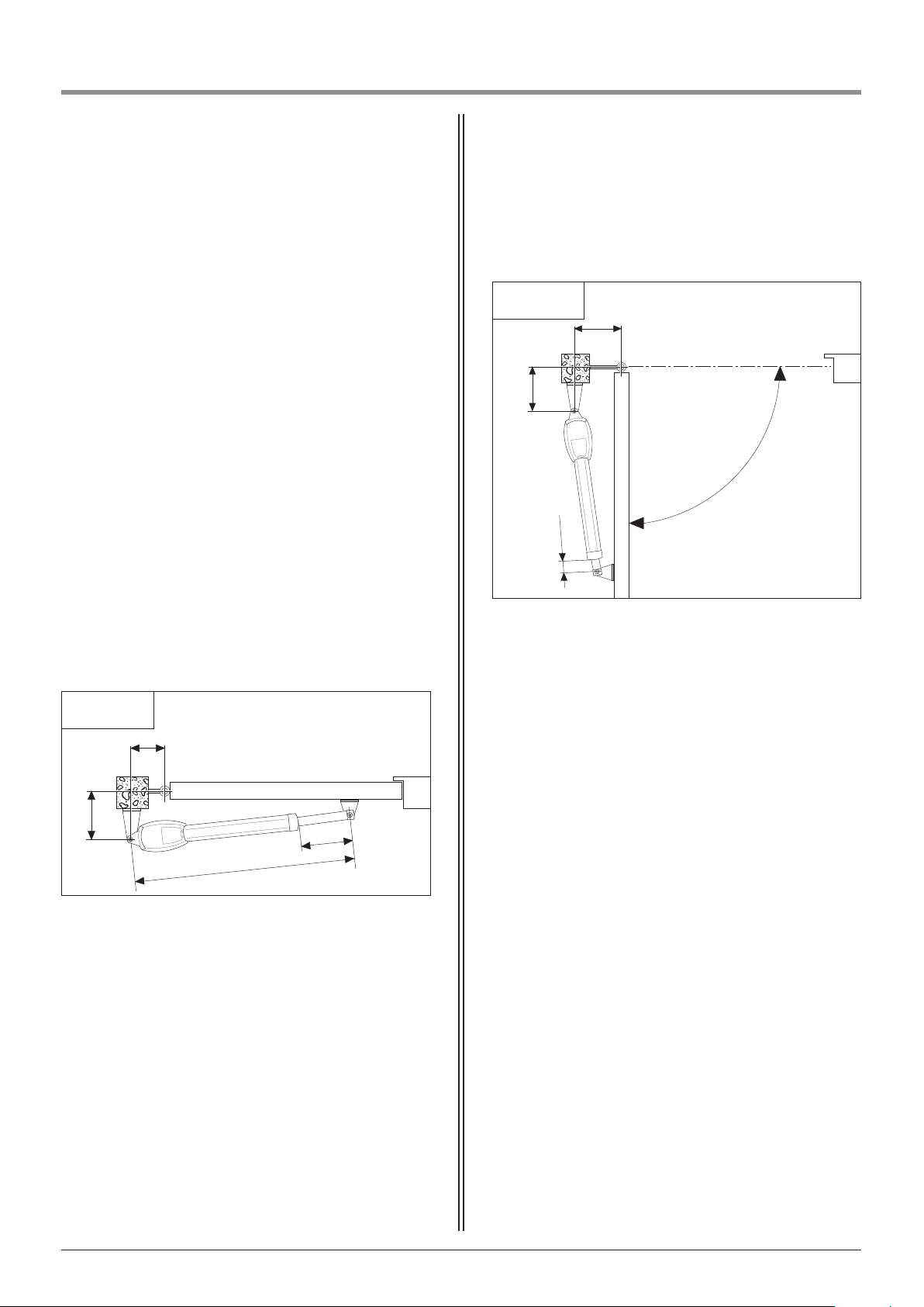
6. Installation
Installation dimensions
6.2 / 1
a
b
c
c1
Gate OPEN
Door in OPEN position / opening angle
The installation dimensions depend upon the local
conditions.
The relevant possible combinations are shown in the
dimensions table.
The following applies here:
- The opening angle (d) is determined by the person
installing the gate.
- The installer also measures out the dimension (b),
which is fixed and cannot be changed.
- When the opening angle (d) and dimension (b) are
known, the corresponding dimension (a) and the
CLOSING movement stroke (c1) can be determined
using the dimension table.
- In the ideal case, dimension (a) and dimension (b) are
approximately equal. This ensures that the hinged
gate moves as smoothly as possible.
- The movement stroke in the OPENING direction (c2)
is fixed and always measures 50 mm.
• Move the gate into the desired OPEN position.
• Measure the opening angle (d).
• Move the door to the CLOSED position.
• Determine dimensions (a) and (b).
The opening angle (d) and dimensions (a) and (b)
provide the value for dimension (c1).
• Determine dimension (c1) using the dimension table.
• Adjust the limit switch to the dimension determined
for (c1).
• Extend the piston rod.
a Dimension (a)
b Dimension (b)
c Max. length of motor unit
c1 Movement stroke CLOSING
c2 Movement stroke OPENING
d Max. opening angle
16 Manual for installation and operation, Comfort 515 GB (#87458)
6.2 / 2
a
b
d
c2
Page 17
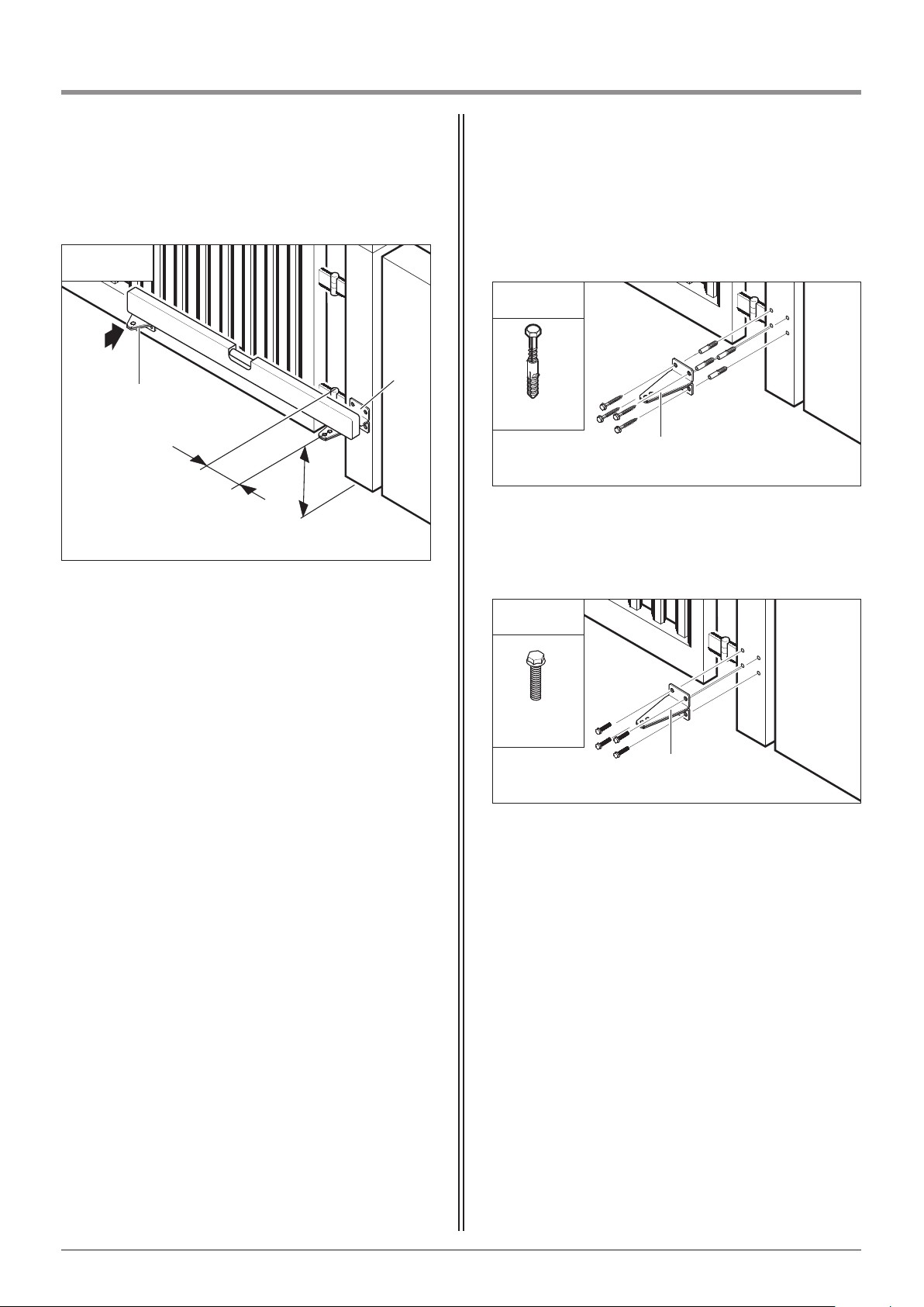
Fixing to a metal post
M8 x 25
• Screw the gate bracket (E) to the post.
• For double wing gate systems, fix the second gate
bracket accordingly on the other side.
6. Installation
6.3 Fixing the post bracket
Fixing to a concrete or stone pillar
8 x 60
• Screw the gate bracket (E) to the post.
6.3 / 1
F
E
E
The vertical position of the gate bracket (E) is dependent
on the position of the gate bracket (F).
• Determine the horizontal position of the gate
bracket (E) on the post with the help of dimension (a).
• Determine the position of the gate bracket (F) on the
gate.
• Transfer the level to the gate bracket (E) using a spirit
level.
• Mark the screw positions on the post.
E
a
≥ 100
6.3 / 2
6.3 / 3
Manual for installation and operation, Comfort 515 GB (#87458) 17
Page 18
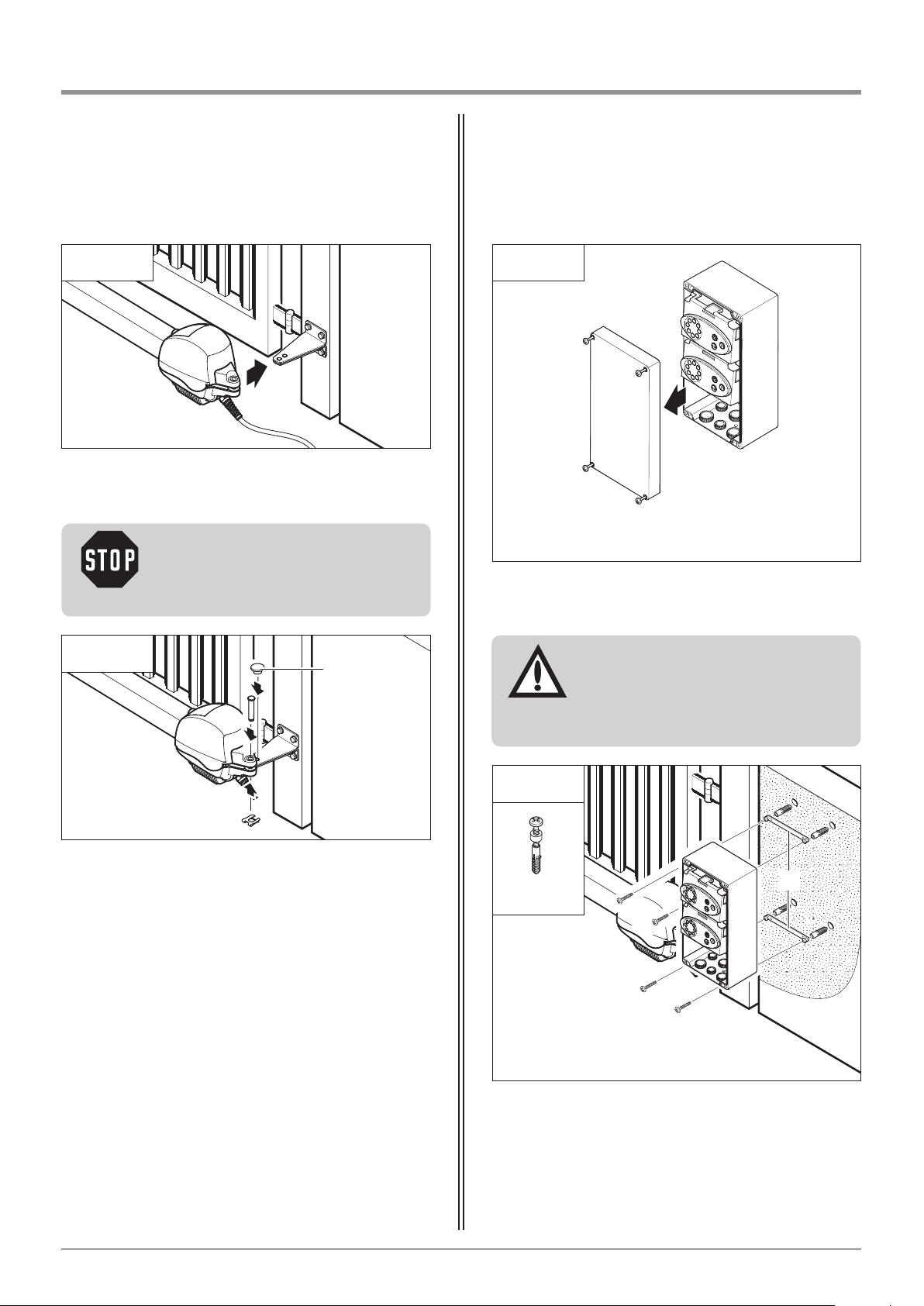
6. Installation
6.4 / 1
• Position the operator on the gate bracket.
6.4 / 2
• Fix the motor unit with the bolt and the locking
plate.
• Push the cover cap (A) into the redundant hole from
above.
• For double wing gate systems, fix the second motor
unit accordingly on the other side.
A
6.5 / 1
6.5 Fixing the control unit
• Open the control unit.
• Mount the control unit using the spacer elements (A).
3,5 x 32
Caution!
To avoid injury, the redundant hole in
the gate bracket must be sealed using
the cover cap (A).
6.5 / 2
Attention!
The control unit must be installed in
such a way that the motor cable can be
fed through the screw fixing at the
base of the control unit.
A
18 Manual for installation and operation, Comfort 515 GB (#87458)
6.4 Fixing the motor unit to the post
bracket
Page 19
6. Installation
Reference:
When installing external control
elements, or safety and signal
equipment, the relevant instructions
must be observed.
i
6.6 Connection of control elements
Attention!
In order to avoid damaging the
controls:
- The local safety regulations must be
complied with at all times.
- It is very important that mains cables
are laid separately from control cables.
- The controls voltage must be 24 V DC.
- If external voltages are applied at
terminals XM70A, XV51A, XM70B,
XV51B, XB99, XP54B, XP54A, XP62B,
XP62A or XB70, the entire electronic
system will be destroyed.
- Only potential-free contacts may be
connected to terminals B9, 5, 34, 3
and 8 (XB99).
Caution!
Danger of electric shock:
Before any cabling works begin, it must
be ensured that the cables are
disconnected from the power supply.
During cabling works, it must be
ensured that the cables remain
disconnected from the power supply at
all times (e.g. prevent reconnection).
P
1
2
3
4
5
6
7
8
1
2
L
N
PE
15
16 17
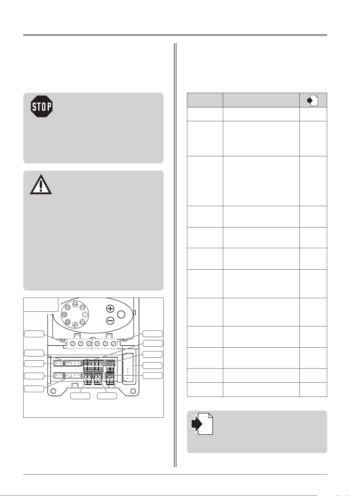
6.6 / 1
XN81
XV51B
XM70B
XM70A
XV51A
XB99
XP54A
XB70
XP54B
XH01
XP62A
XP62B
Label Type / function
i
XB70 Connection of modular antenna 8.1
XB99
Connection of external control
elements
6.6 / 2
6.6 / 3
6.6 / 4
6.6 / 5
XH01
Connection for programmable
output 16/17 (e.g. signal light,
24 V DC, 0,5 A,
max 24 V/10 W)
Electric lock 15/16 (24 V DC)
6.6 / 6
6.6 / 7
XM70A
Connection for motor unit
(MASTER)
6.7 / 5
6.7 / 8
XM70B
Connection for motor unit
(SLAVE)
6.7 / 5
6.7 / 8
XN81 Connection for mains cable
6.6 / 6
6.8
XP54A
Connection for closing edge
safety device, gate travelling
direction CLOSE
6.6 / 8
XP54B
Connection for closing edge
safety device, gate travelling
direction OPEN
6.6 / 8
XP62A
Connection for photocell,
gate travelling direction CLOSE
6.6 / 9
XP62B
Connection for photocell,
gate travelling direction OPEN
6.6 / 9
XV51A Connection has no function -
XV51B Connection has no function -
Manual for installation and operation, Comfort 515 GB (#87458) 19
Page 20
6. Installation
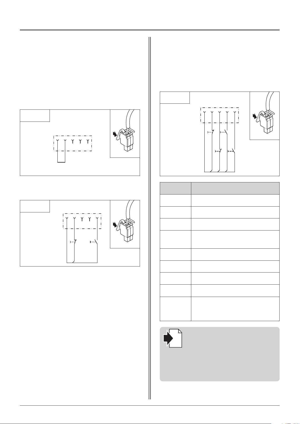
Terminal XB99
Factory settings:
B9 and 5 bridged
Connection option 1:
6.6 / 2
6.6 / 3
Connection option 2:
Reference:
The connection configuration depends
on the programming of the special
functions. Depending on the programming, impulse or direction buttons can
be connected.
Programming the special functions is
described in Section 9.4 (Level 5).
i
6.6 / 4
Label Type / function
3 Active wing connection
5 Stop connection
8 Impulse connection
34
Connection for closing prevention device
(Photocell)
B9 +24 V DC connection
SB3 Active wing connection
SB5 STOP button
SB8 Impulse button
SB34
Button for closing prevention device
(Photocell) /
Drive system stops and reverses
M06E039
M06E039
M06E039
20 Manual for installation and operation, Comfort 515 GB (#87458)
B9 5 34 3 8
-XB99
B9 5 34 3 8
-XB99
B9 5 34 3 8
-XB99
12 11
-SB5
14 13
-SB3
12 11
-SB3 4
14 13
-SB8
12 11
-SB5
14 13
-SB8
Page 21
6. Installation
Advice:
If a closing prevention device
(photocell, timer, …) is connected to
XB99, the controls will recognise it
automatically after “Mains On”
(contact SB34 must be closed).
The photocell can be deactivated later
(Level 8 / Menu 1).
When the contacts of a closing
prevention device are open, the gate
can no longer be closed.
Additional external control elements,
and safety and signal devices with 24 V
connections must be connected to
XB99 and XH01.
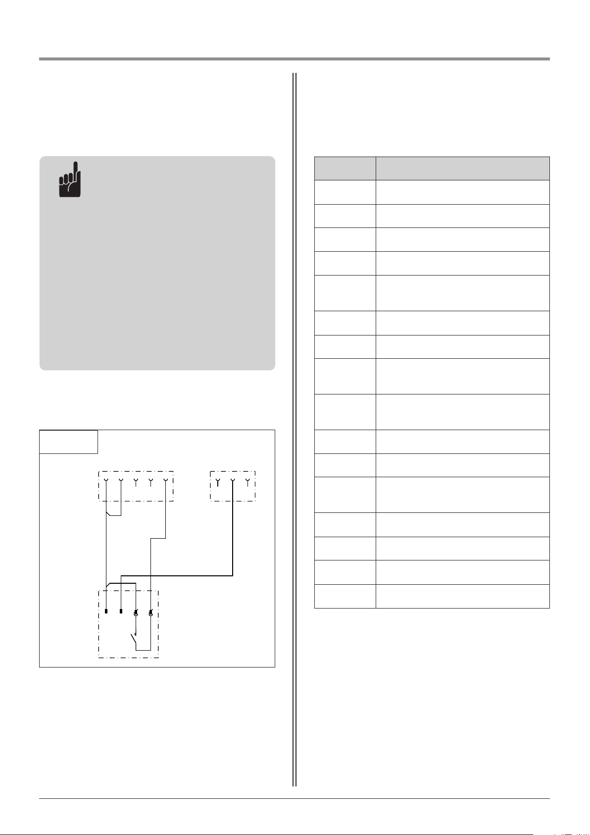
Connection option 3:
- External radio receiver
6.6 / 5
Label Type / function
XB99 Connection of external control elements
3 Active wing connection
5 Stop connection
8 Impulse connection
34
Connection for closing prevention device
(Photocell)
B9 24 V DC connection
X1 Connection for external receiver
1
Connection of potential-free normally open
contact
2
Connection of potential-free normally open
contact
+ 24 V DC connection
- GND connection
S1
Normally open contact, receiver,
potential-free
XH01 Connection of control unit output
15 Connection for electric lock, 24 V DC
16 GND connection
17 Connection for programmable output
M07E027
Manual for installation and operation, Comfort 515 GB (#87458) 21
- XB99
- X1
B9 5
+
- S1
34
3 8
-
1 2
14 13
- XH01
15 16 17
Page 22
6. Installation
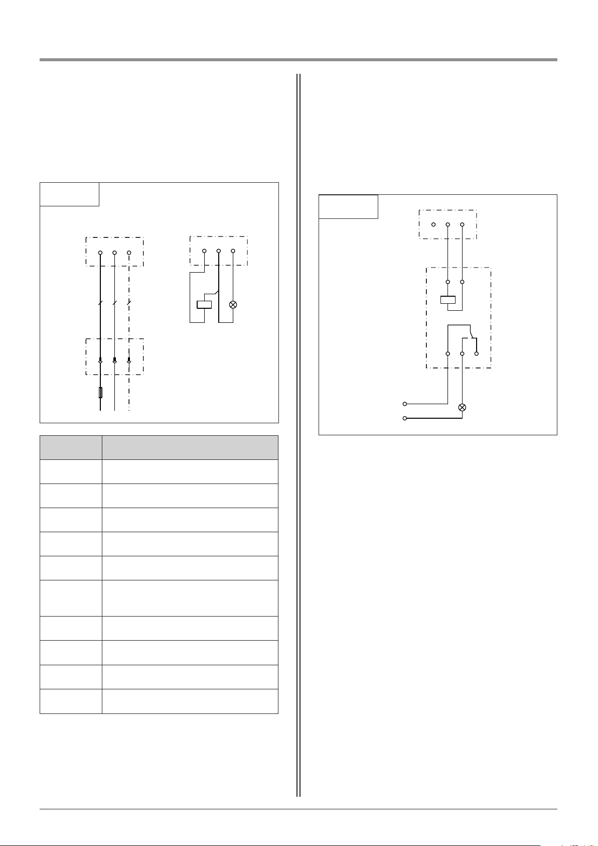
Terminals XN81 / XH01 Connection option:
- Connection for signal light with external relay
6.6 / 6
- XH01
161517
1411
12
A2 A1
- KH17
- HH14
L
N
M07E039
M07E038
6.6 / 7
M07E038
Label Type / function
L Connection for phase
N Connection for neutral wire
PE Earth wire connection
15 / 16 Connection for electric lock, 24 V DC
16 GND connection
16 / 17
Connection of programmable output
(24 V DC / 0.5 A)
HH14 Signal light
HH17 Signal light 24 V
KH17 User’s relay 24 V
YH15 Electric lock (provided by the customer)
22 Manual for installation and operation, Comfort 515 GB (#87458)
- XN81
L
PE
N
NLPE
- XH01
15
- YH15
17
16
- HH17
- X0
LPEN
- F0
Page 23
6. Installation
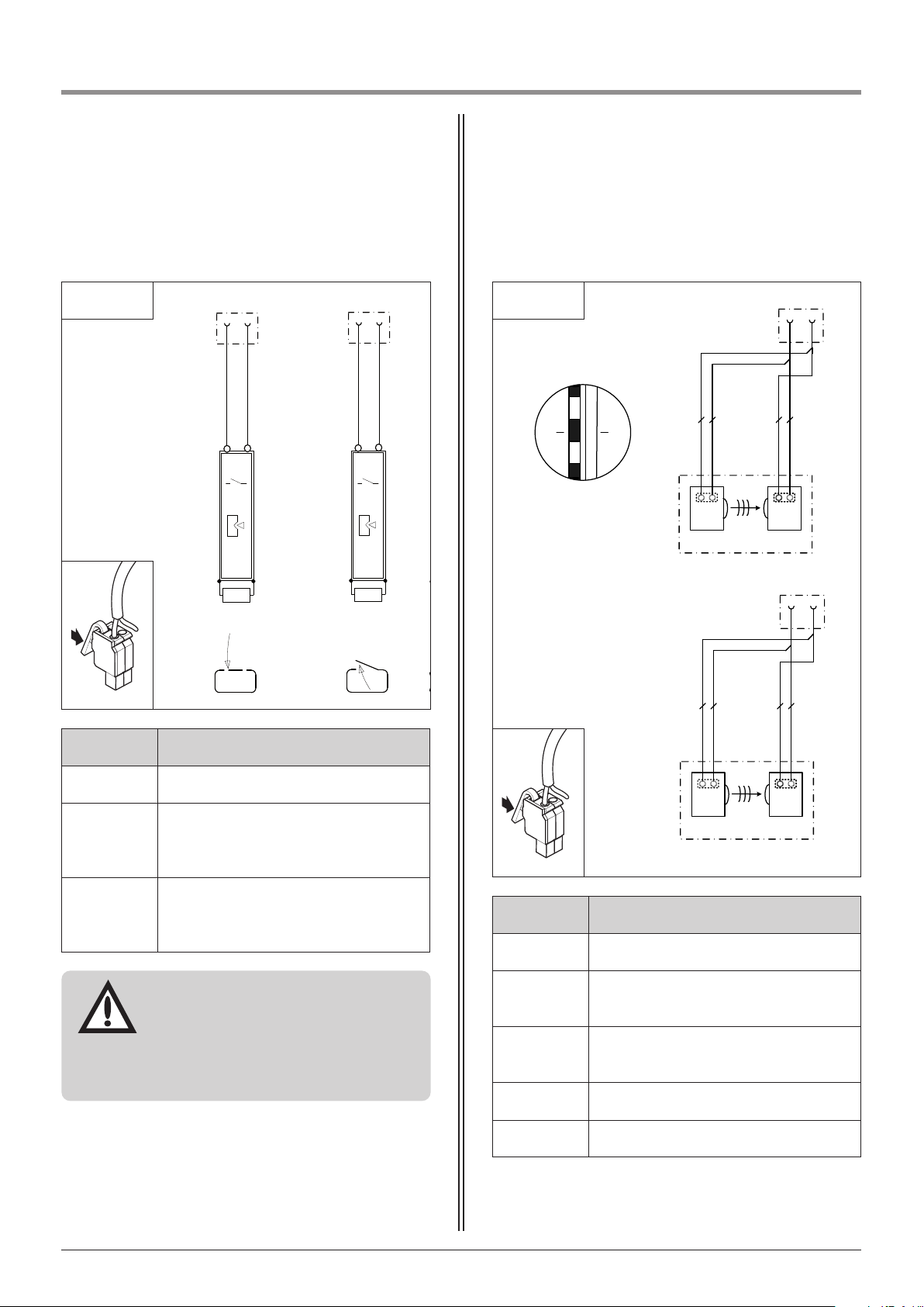
Label Type / function
P6 GND connection
26
Connection for photocell signal
gate travelling direction OPEN (XP62B)
27
Connection for signal of photocell, gate
travelling direction CLOSE (XP62A)
RX Receiver for the two-wire photocell
TX Transmitter for the two-wire photocell
Terminals XP62A / XP62B
- XP62A
P6 27
TX
RX
- W1
2
1
- W2
2
1
1
2
- W1
- W2
- AP27
-
- XP62B
P6 26
TX
RX
- W1
2
1
- W2
2
1
- AP26
6.6 / 9
Terminals XP54A / XP54B
Label Type / function
P5 GND connection
46
Connection for signal of closing edge safety
device
Gate travelling direction OPEN (XP54B)
47
Connection for signal of closing edge safety
device
Gate travelling direction CLOSE (XP 54A)
Attention!
If an 8.2 kΩ contact strip closing edge
safety device is connected, the 8.2 kΩ
resistors installed at terminals XP54B
closing edge OPEN and XP54A closing
edge CLOSE must be removed.
- XP54B
P5
46
- XP54A
P5 47
8K2
8K2
- XP54B
P5
46
8K2
6.6 / 8
M07E037 M07E036
Manual for installation and operation, Comfort 515 GB (#87458) 23
Page 24
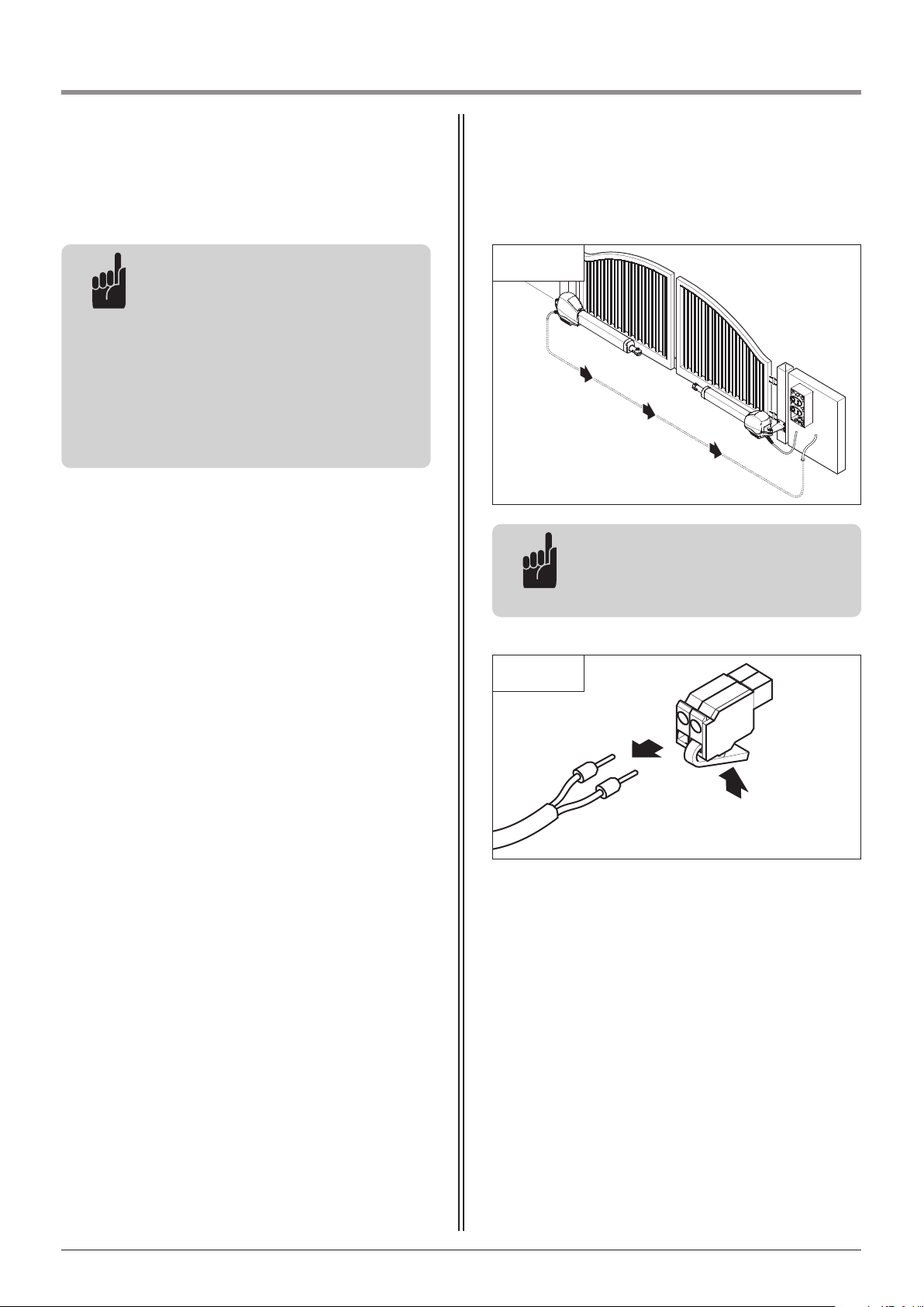
6.7 Connecting the operator to the
controls
6.7 / 1
A2
A1
• Pull the leads out of the motor plug.
6.7 / 2
Advice:
For double-wing gate systems, both
the mains cables must be laid to the
controls.
6. Installation
Advice:
A two-wire photocell connected to
terminals XP62B / XP62A will be
recognised automatically by the
controls after “Mains On”.
The photocell can be deactivated later
(Level 8 / Menu 1).
If the contacts of a closing prevention
device are open, the gate can no longer
be closed.
24 Manual for installation and operation, Comfort 515 GB (#87458)
Page 25
6. Installation
1
2
3
4
5
6
7
8
1
2
1
2
3
4
5
6
7
8
1
2
L
N
PE
15
16 17
P
P
6.7 / 5
B
C
XM70B
XM70A
6.7 / 3
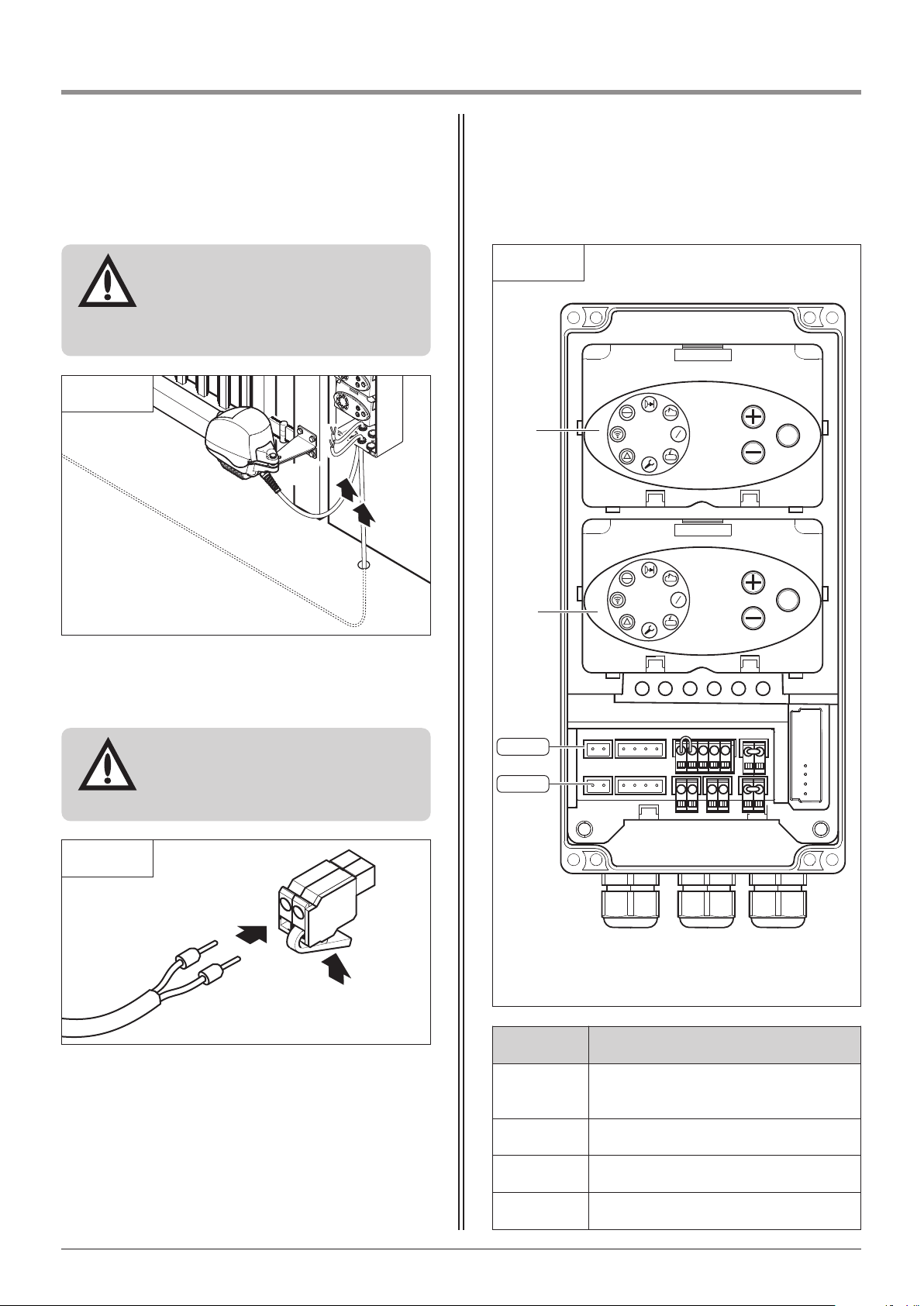
• Feed the cables from the motor units into the control
unit through the screw fixings.
Attention!
In order to guarantee the protection
grade of the controls, the cables must
be fed through the corresponding
screw fixing (A).
A2
A1
Poles:
A1 Brown lead
A2 Green lead
• Insert the leads into the motor plug.
6.7 / 4
Attention!
To ensure that the motor unit rotates in
the correct direction, the poles of the
plug must be connected correctly.
Manual for installation and operation, Comfort 515 GB (#87458) 25
Label Type / function
B
Control module SLAVE
(only for double wing gates)
C Control module MASTER
XM70A Connection for motor unit (Master)
XM70B Connection for motor unit (Slave)
Page 26
6. Installation
L
N
PE
15
16 17
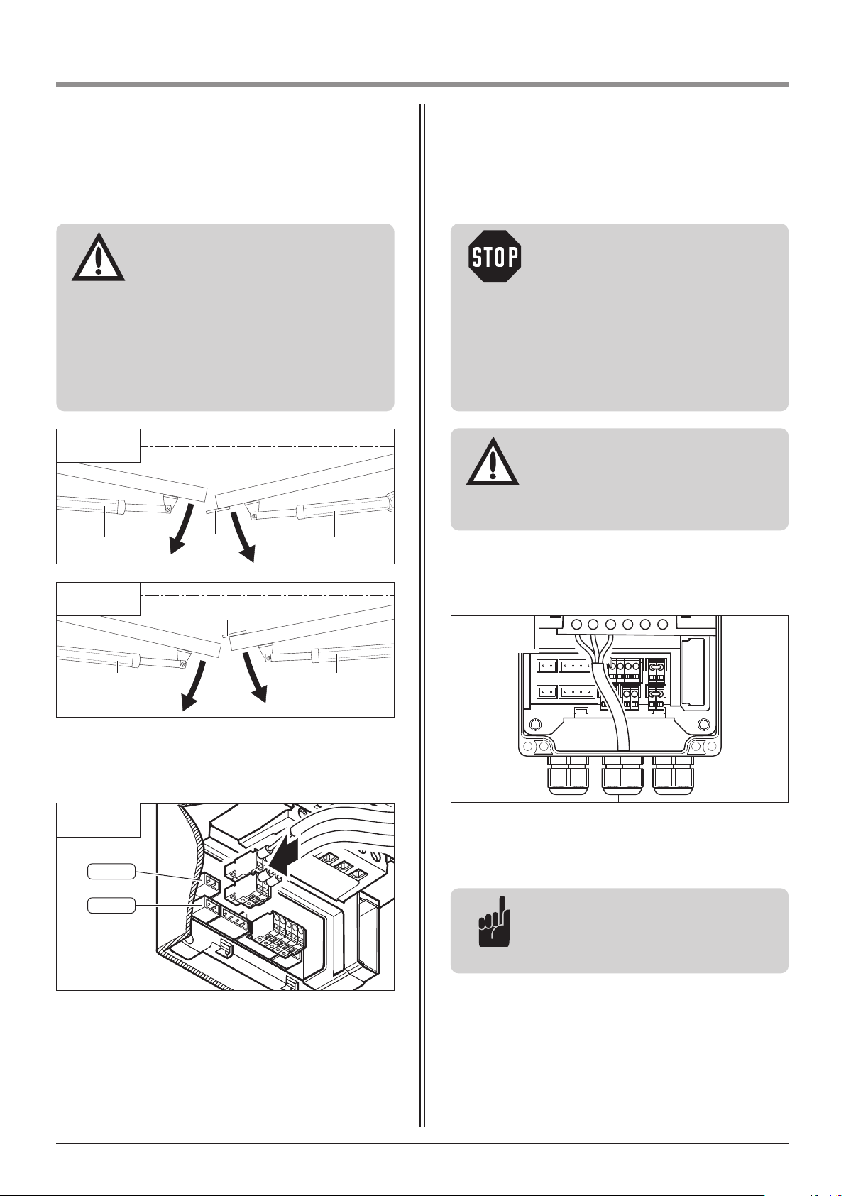
• Connect the power supply leads to the control unit.
• Connect the control unit to the electricity supply.
Advice:
All the control lights light up for
approx. 3 seconds. Then LED 8 is lit.
Other LEDs may also be lit.
Attention!
In order to guarantee the protection
grade of the controls, the cable must
be passed through the correct screw
fixing.
• Feed the cable through the screw fitting into the
control unit.
6.8 Connection of the mains cable
Caution!
- During cabling works, the supply
cables must be disconnected from the
power supply. It must be ensured that
the cables remain disconnected from
the supply for the duration of the
cabling works.
- The fixed connection of a mains
supply requires a universally poled
mains disconnection facility.
6.8 / 1
PE
N
L
15
16
17
Attention!
To ensure trouble free operation, the
following must be ensured:
- For a single-wing gate system, the
motor unit must always be connected
to the MASTER (XM70A) connection.
- For a double-wing gate system, the
overlap (D) must be taken into
consideration when connecting the
motor units.
E SLAVE motor unit
F MASTER motor unit
6.7 / 8
• Connect the motor units to the controls.
6.7 / 6
F
D
E
D
EF
6.7 / 7
XM70B
XM70A
26 Manual for installation and operation, Comfort 515 GB (#87458)
Page 27
6. Installation
6.9 Setting the CLOSED and OPEN gate positions
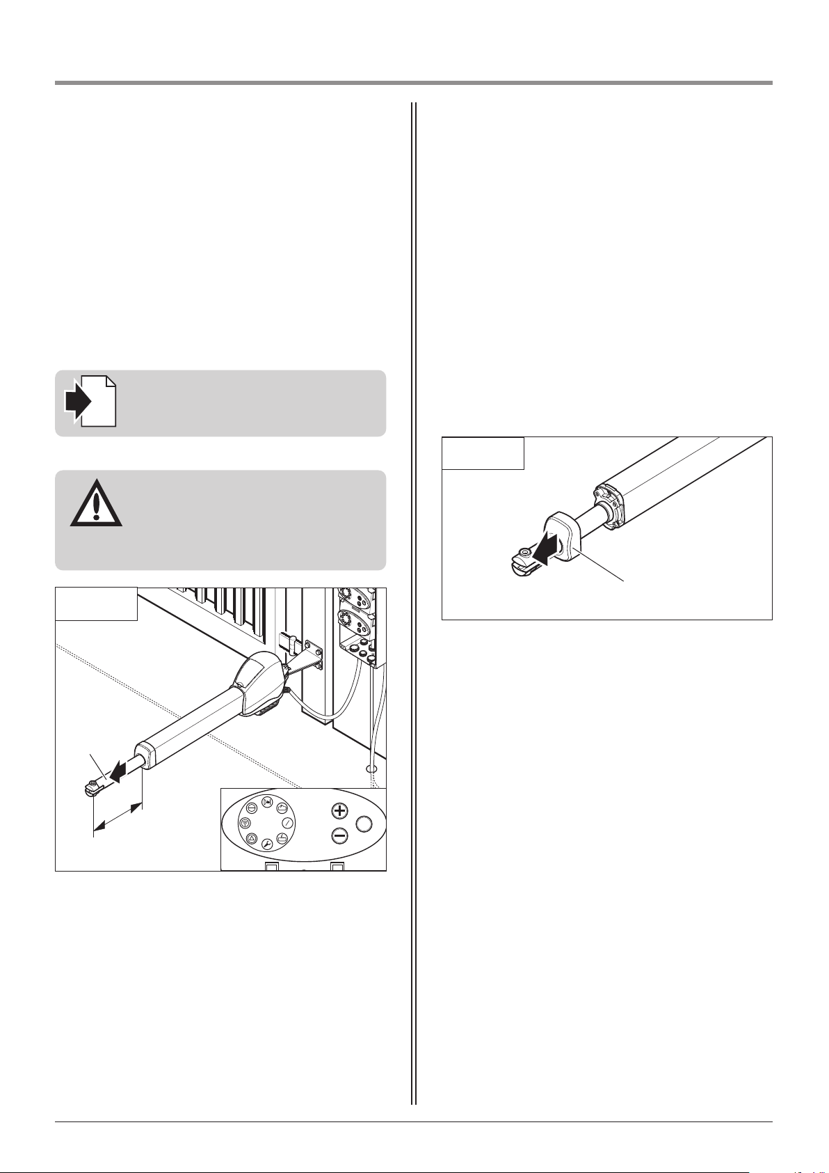
6.9.1 Setting the gate CLOSED position
• Drive the gate in the direction of CLOSING by
pressing the (–) button.
• Measure the movement stroke (c1):
Attention!
The connecting rod (A) must be held in
position when closing the gate to
prevent it from turning as the gate
turns.
6.9.1 / 1
C1
A
The CLOSED gate position is determined by the length
of the connecting rod (A).
To achieve the correct CLOSED gate position, the
length of the visible part of the connecting rod (A)
must be equal to the CLOSING movement stroke (c1)
as given in the dimensions table.
The CLOSING movement stroke (c1) is dependent on
the site-dependent dimensions (a) and (b).
Reference:
The relevant dimensions are given in
the table in Section 6.2.
i
1
2
3
4
5
6
7
8
1
2
P
6.9.1 / 2
• Take off the protective cap (B).
B
The CLOSING movement stroke (c1) must be adjusted
using the adjusting screw (C) if the values disagree.
Increase the movement stroke:
Turn the adjusting screw (C) in the (+) direction.
Decrease the movement stroke:
Turn the adjusting screw (C) in the (-) direction.
Turning the adjusting screw (C) by 360° adjusts the
movement stroke by 1.25 mm.
Manual for installation and operation, Comfort 515 GB (#87458) 27
Page 28
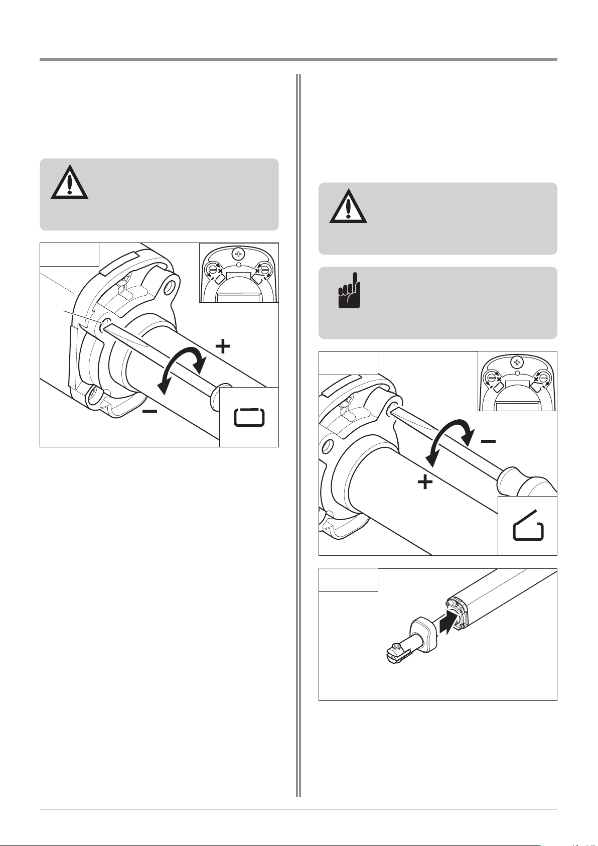
6.9.2 Setting the gate OPEN position
6.9.2 / 1
The gate OPEN position is pre-set.
Advice:
Fine adjustments to the gate OPEN
position can be made by turning the
adjusting screw in the (+) or (-)
directions.
6.9.2 / 2
• Fit the protective cap on the motor unit.
6. Installation
6.9.1 / 3
• Turn the adjusting screw in the (+) or (-) direction to
set the CLOSED position.
• Drive the gate a little in the OPENING direction by
pressing the (+) button.
• Drive the gate back to the CLOSED position by
pressing the (-) button.
• Compare the movement stroke (c1) from the
dimensions table with the movement stroke (c1) as
measured.
• Repeat the process until the CLOSING movement
stroke (c1) from the dimensions table agrees with the
measured CLOSING movement stroke (c1).
C
Attention!
The CLOSED position may only be
adjusted using a manual screw driver,
to ensure that the adjusting mechanism
is not damaged.
Attention!
The OPEN position may only be adjusted
using a manual screw driver, to ensure
that the adjusting mechanism is not
damaged.
28 Manual for installation and operation, Comfort 515 GB (#87458)
Page 29
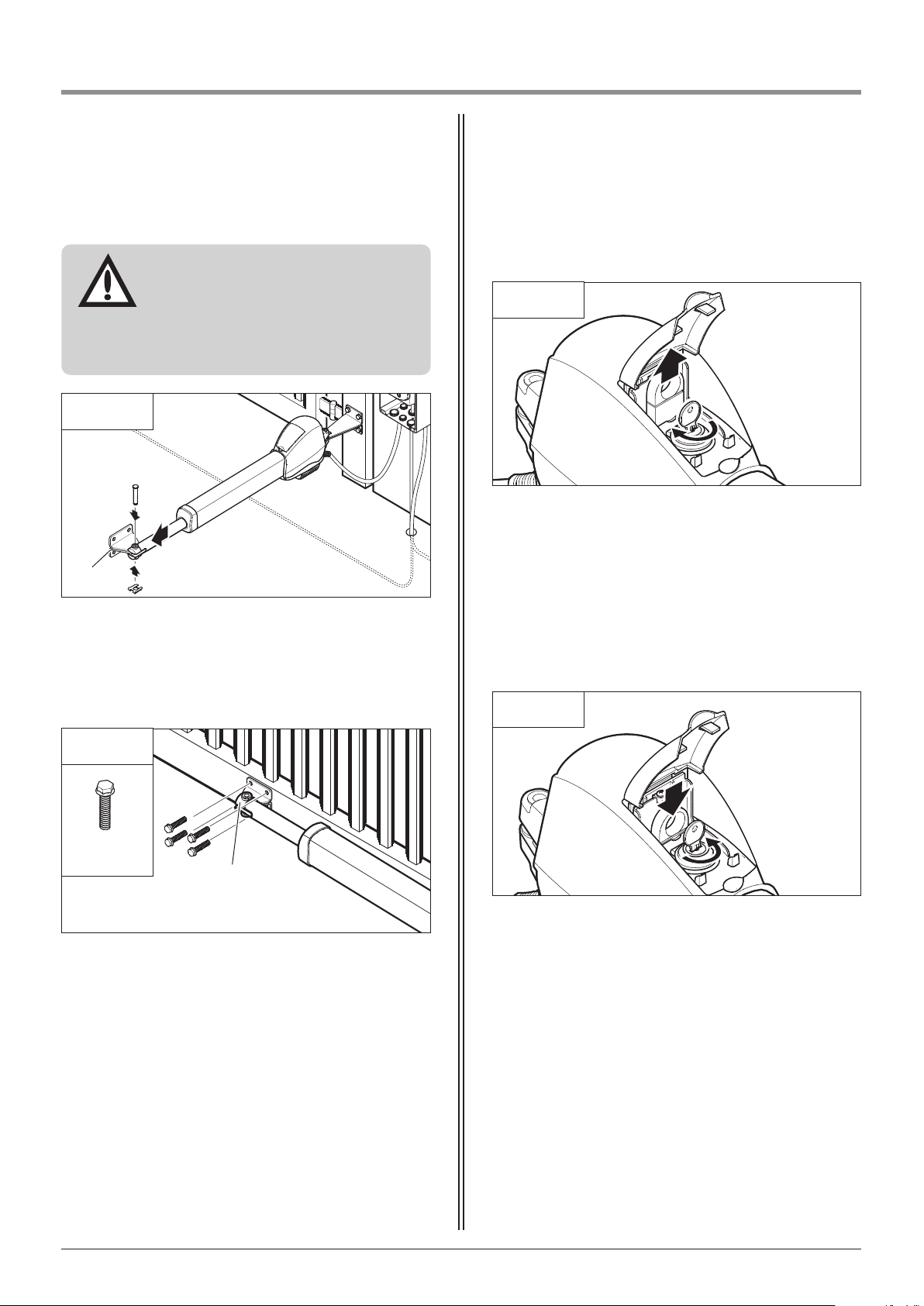
6.11 Release
6.11 / 1
Releasing
• Turn the key through 180°.
• Lift up the red release lever.
• Turn the key 180° in the opposite direction to secure
the released position.
6.11 / 2
Locking
• Turn the key through 180°.
• Press down the red release lever.
• Turn the key 180° in the opposite direction to secure
the locked position.
6. Installation
6.10 / 1
• Drive the motor unit to the gate CLOSED position.
• Secure the gate bracket (A) with the bolt and the
locking plate.
Attention!
To ensure the successful mounting of
the gate bracket:
- The motor unit must be in the
CLOSED position.
- The gate must be closed.
M8 x 25
• Close the gate.
• Screw the gate bracket (A) to the gate.
• For double-wing gates, mount the second gate
bracket accordingly on the opposite side.
6.10 Mounting the gate bracket
A
A
6.10 / 2
Manual for installation and operation, Comfort 515 GB (#87458) 29
Page 30
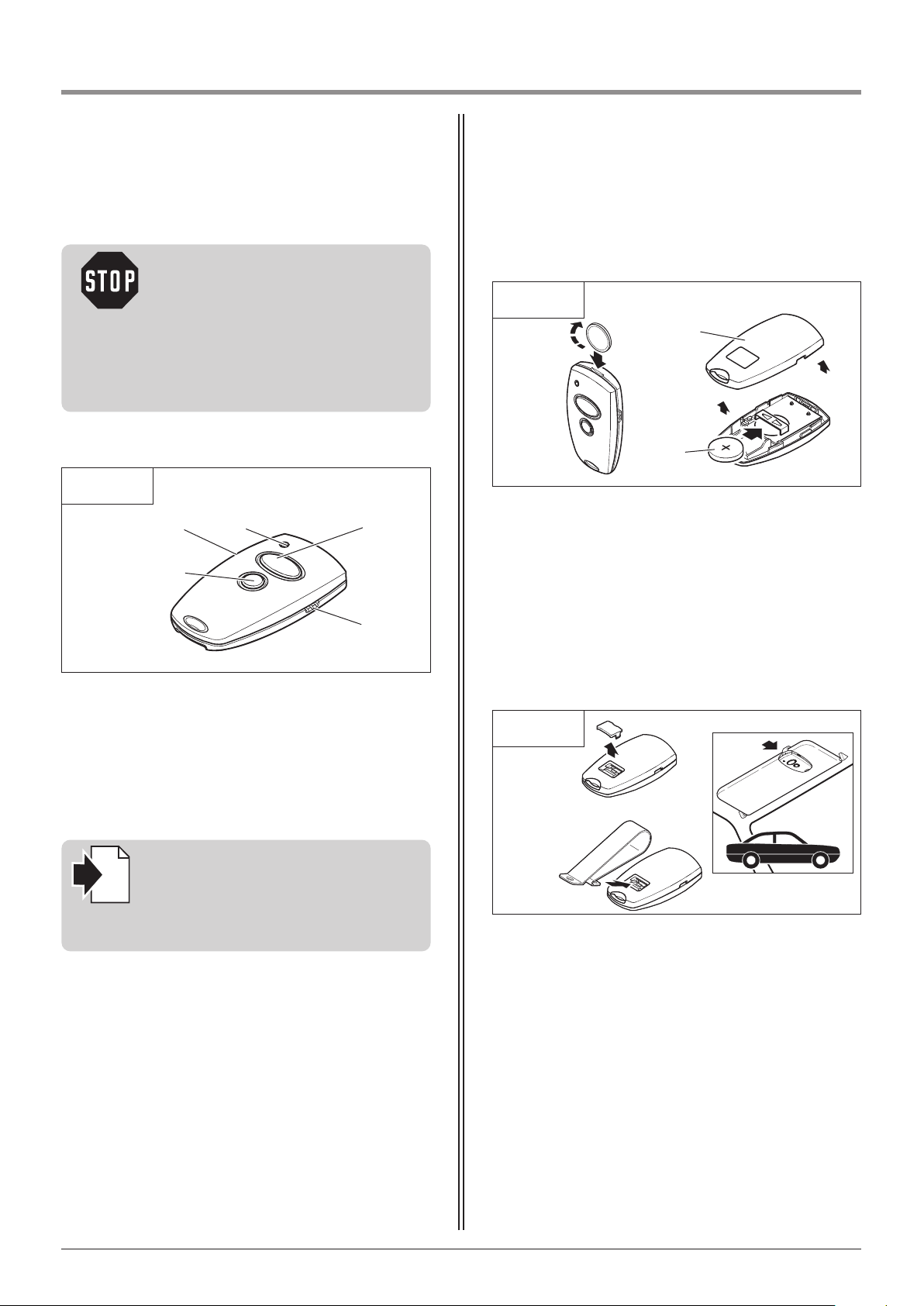
1
7.1 Operation and accessories
E Back of hand transmitter
F Battery 3V CR 2032
• Open the back of the hand transmitter (E),
e.g. with a coin.
• Change the battery (F) and observe correct poling.
Caution!
Children are not allowed to operate the
hand transmitters!
Before operating the hand transmitter,
make sure that there are neither
persons nor objects in the operating
range of the gate.
A
D
B
D
C
F
E
Visor clip, for attaching the hand transmitter to a visor
in a car.
7.1 / 1
7.1 / 2
7.1 / 3
7. Hand transmitter
A Operating button - large
B Operating button - small
C Battery - transmission control light
D Transmission socket
Another operator system can be operated using the
second operating button.
Overview
Accessory
Change batteries
Reference:
The procedure for programming hand
transmitters (remote controls) to
operate the operator system is
described in Section 8.4.3.
i
30 Manual for installation and operation, Comfort 515 GB (#87458)
Page 31
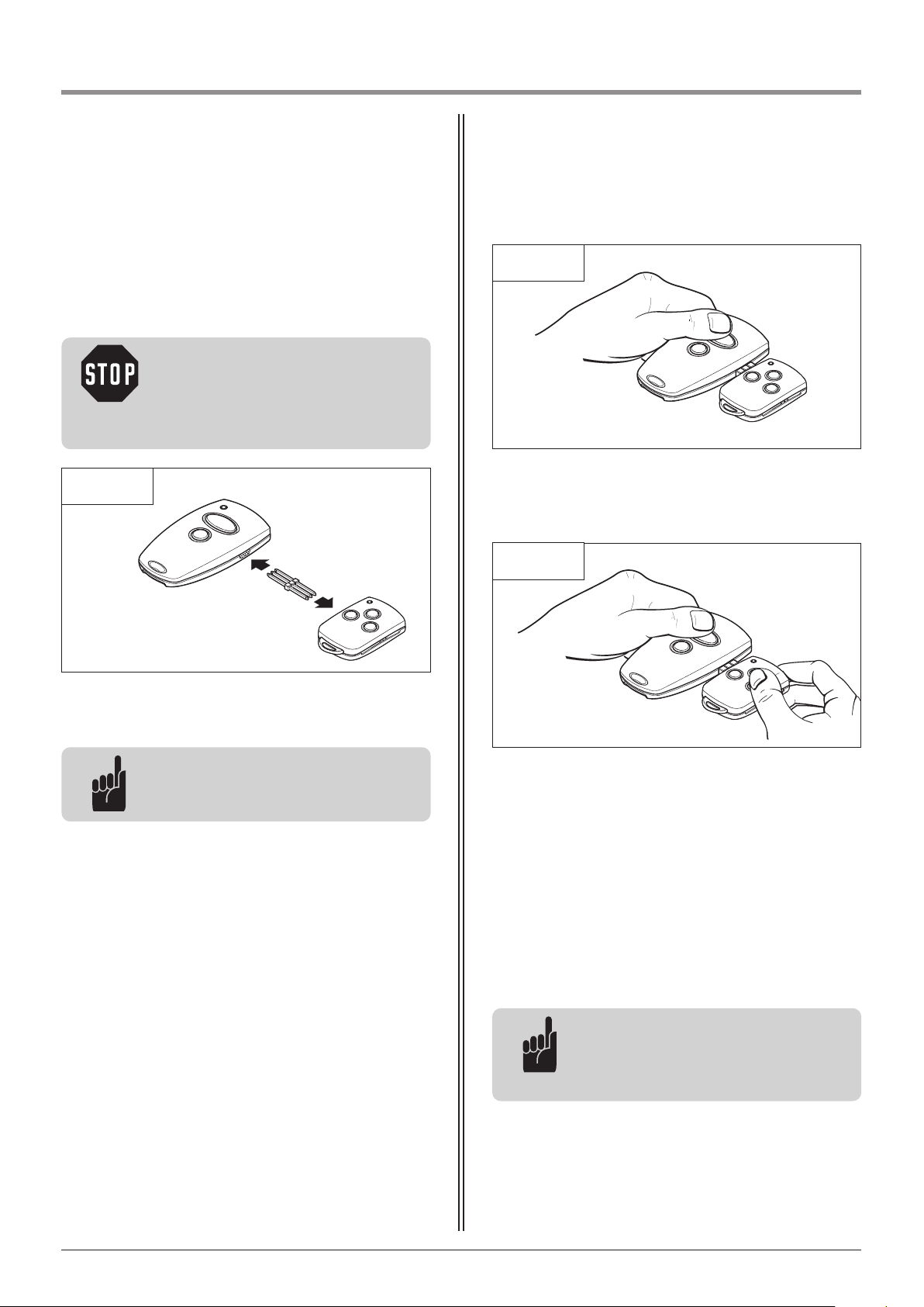
7. Hand transmitter
7.2 Hand transmitter coding
7.2.1 Transfer the coding
Advice:
The plug connections on both sides of
the hand transmitter are identical.
Advice:
For multi-channel hand transmitters,
the coding procedure has to be carried
out for each button separately.
Using this function it is possible to transfer the coding
of a hand transmitter that has already been
programmed for operating the operator system
(master transmitter) to another hand transmitter.
• Connect both transmitters with the enclosed
transmission plug.
• Actuate the master transmitter and hold the button.
The transmitter LED lights up.
• Whilst keeping the button on the master transmitter
depressed, press the desired button on the other
hand transmitter.
The LED flashes.
After 1 – 2 seconds, the LED on the newly programmed transmitter lights up permanently.
The programming procedure is complete.
The coding of the master transmitter has now been
transferred to the other hand transmitter.
• Remove the transmission plug.
Caution!
Before operating the hand transmitter,
ensure that there are neither persons
nor objects in the operating range of
the gate.
7.2.1 / 1
7.2.1 / 2
7.2.1 / 3
Manual for installation and operation, Comfort 515 GB (#87458) 31
Page 32
P
E
N
L
15
1
6
1
7
7. Hand transmitter
8.1 / 1
A
B
• Insert the modular antenna (A) into the antenna
socket (B).
8.1 Connecting the modular antenna
8. Initial operation
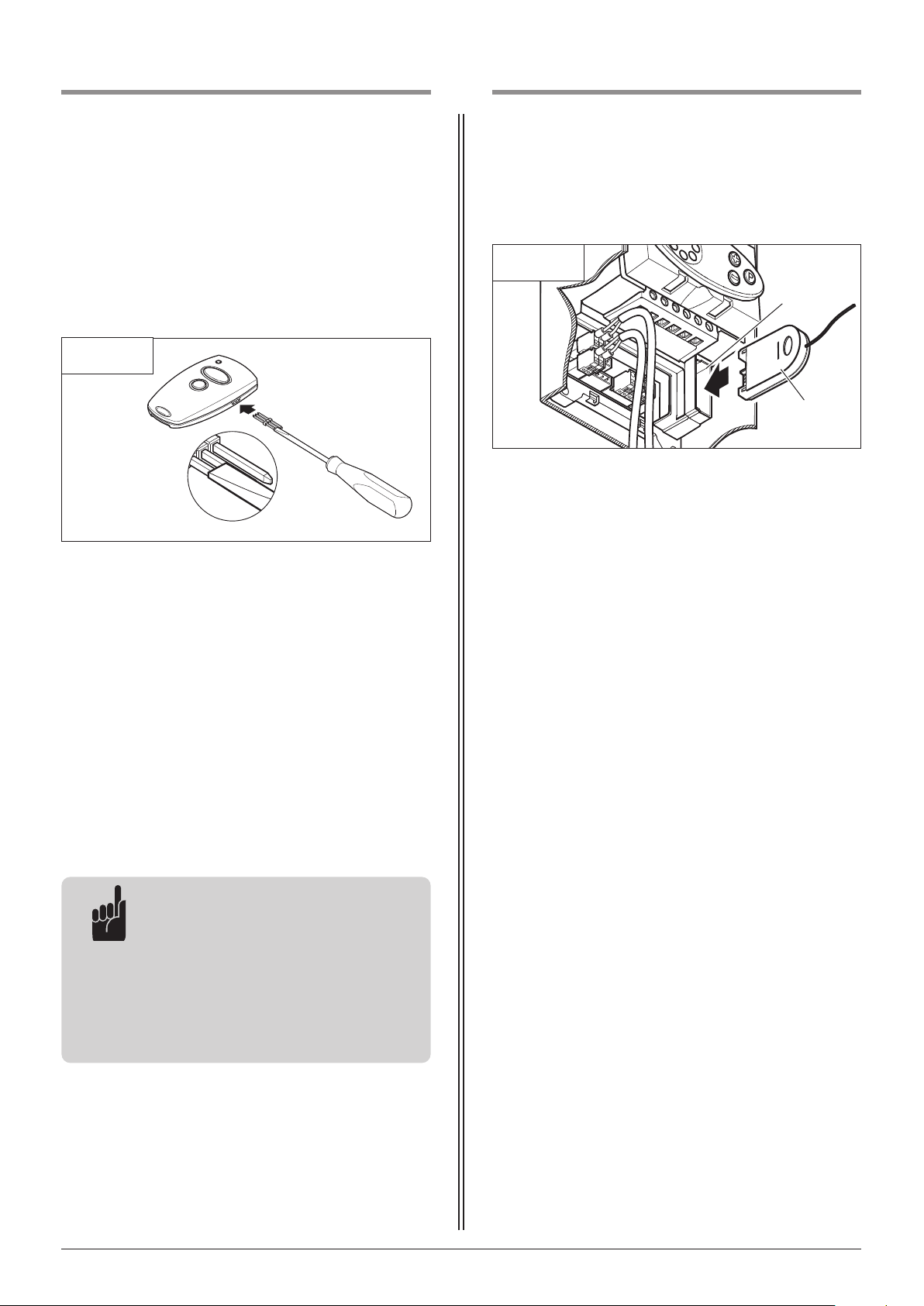
7.2.2 Change coding
If a hand transmitter has been lost, this function can
be used to change the coding of the remaining remote
control transmitters.
• Connect one end of the transmission plug to the
hand transmitter.
• At the free end of the transmission plug, short-circuit
one of the outer pins with the centre pin adjacent to
it (e.g. using a screw driver).
• Press the desired button on the hand transmitter.
A new code is then generated by the integrated
random coding facility.
The LED flashes quickly.
As soon as the LED lights up permanently, the hand
transmitter has been programmed with a new code.
The button can then be released and the transmission
plug removed.
Advice:
After the hand transmitter has been
re-programmed, the operator system
must also be re-programmed to
respond to the new code.
For multi-channel transmitters, the
programming process must be carried
out for each button separately.
7.2.2 / 1
32 Manual for installation and operation, Comfort 515 GB (#87458)
Page 33
8. Initial operation
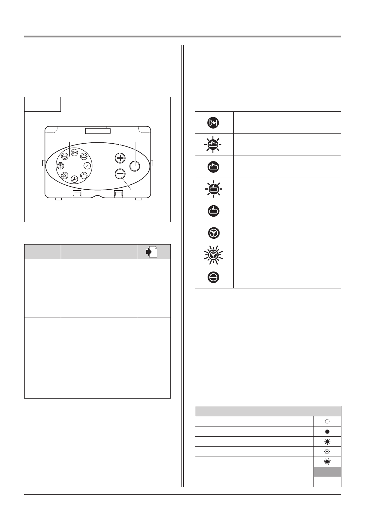
8.3 Overview of the display functions
Photocell or the CESD has been interrupted
(display: master only)
Gate moving towards OPEN position
(display: master and slave)
Gate in OPEN position
(display: master and slave)
Gate moving towards CLOSED position
(display: master and slave)
Gate in CLOSED position
(display: master and slave)
Permanent actuation of an external control
element (display: master only)
Remote control is actuated
(display: master only)
Operating voltage
(display: master and slave)
LED displays in operating mode
Legend:
LED off
LED on
LED flashes slowly
LED pulses
LED flashes quickly
Factory default setting
Not possible –
8.2 Overview of the control unit
P
1
2
3
4
5
6
7
8
1
2
BAD
C
8.2 / 1
Operating elements
Label Type / function
i
A Carousel display 8.3
B
OPEN button (+)
(e.g. to drive the gate to
the OPEN position or to
increase parameters when
programming)
-
C
CLOSE button (-)
(e.g. to drive the gate to
the CLOSED position or to
decrease parameters when
programming)
-
D
STOP button (p)
(e.g. to switch to
programming mode or
to save parameters)
-
Manual for installation and operation, Comfort 515 GB (#87458) 33
Page 34
8. Initial operation
8.4 Express programming
The following works must be carried out before the
operator can be put into operation successfully:
- The remote control must be programmed in the
express programming procedure.
- The soft running feature must be set up by means of
four learning runs.
After switching on (mains on):
- The controls do not show a gate position signal yet.
- The system always runs in the direction of the OPEN
position after the first impulse.
When the system is already in the OPEN position, only
the display changes after the first impulse, to indicate
the OPEN position. After a second impulse the gate
then runs in the direction of the CLOSED position.
8.4.1 General notes on express programming 8.4.2 Programming buttons
The controls are programmed using the plus (+),
minus (-) and (P) buttons.
If no buttons are pressed within 120 seconds while in
programming mode, the controls revert to operating
mode.
A corresponding message is displayed.
Reference:
The messages are explained in
Section 10.
i
Attention!
In order to ensure proper operation,
the express programming must be
carried out at the MASTER control unit.
• Carry out the express programming according to the
following procedure.
34 Manual for installation and operation, Comfort 515 GB (#87458)
Page 35
8. Initial operation
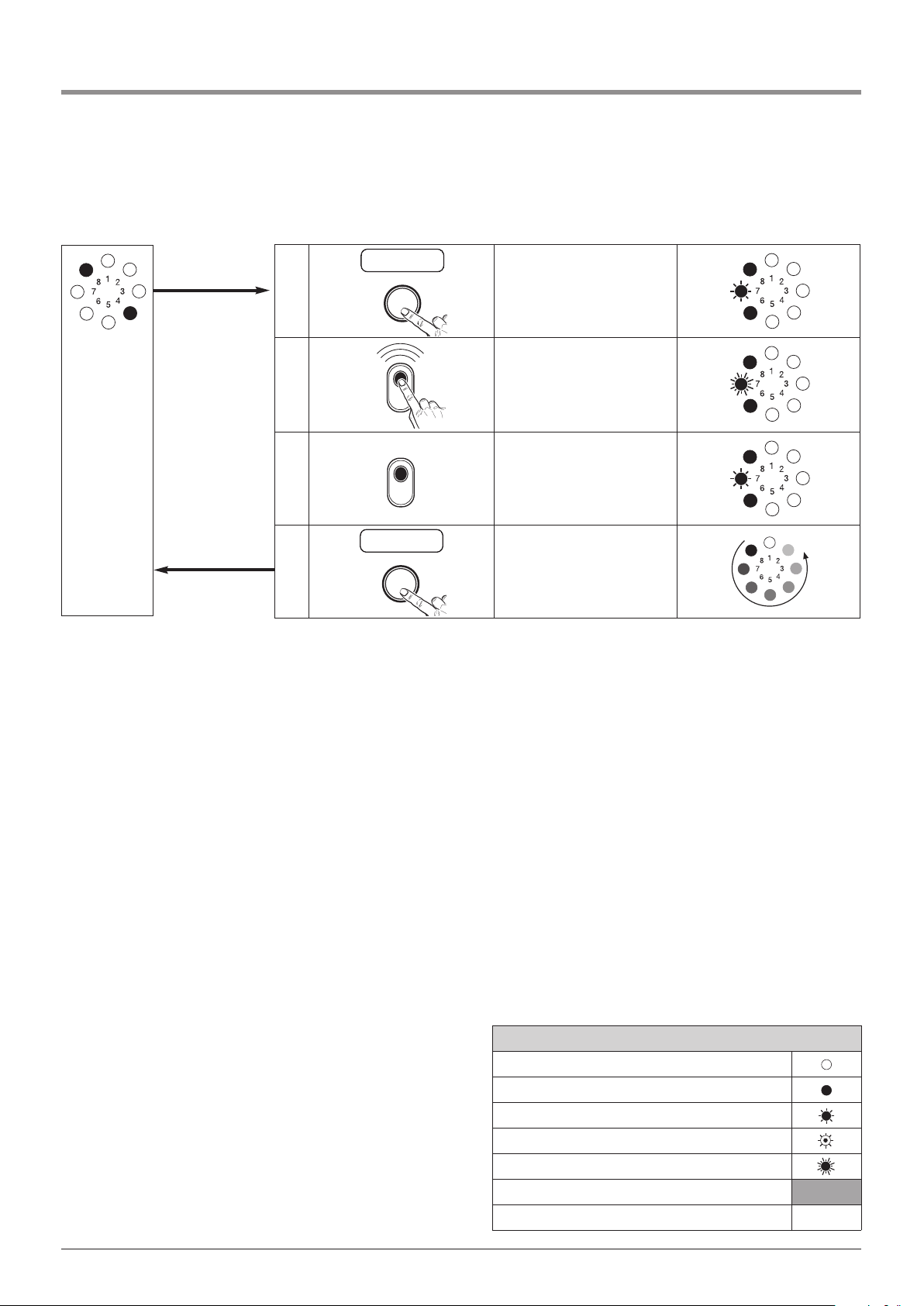
8.4.3 Express programming sequence
Operating
mode
1.
P
1x >2s <10s
Start express
programming /
Programme the remote
control
2.
Press the hand transmitter
button
3.
Release the hand transmitter
button
4.
P
1x <1s
Save the remote control
settings /
End the express
programming procedure
Legend:
LED off
LED on
LED flashes slowly
LED pulses
LED flashes quickly
Factory default setting
Not possible –
Manual for installation and operation, Comfort 515 GB (#87458) 35
Page 36
8. Initial operation
8.5.2 Checking the automatic cut-out
• Place an obstacle in the path of the gate in both the
OPEN and CLOSE directions.
• For each direction, drive the gate into the obstacle.
The operator system must stop and reverse when
it hits the obstacle.
Caution!
The automatic cut-out must be
correctly programmed for the CLOSE
and OPEN directions to prevent
damage to persons or property.
• Use the operator system (with the door coupled) to
drive the door to the CLOSED position.
• Use the operator system (with the door coupled) to
drive the door once from the CLOSED position to the
OPEN position and back to the CLOSED position without interruption.
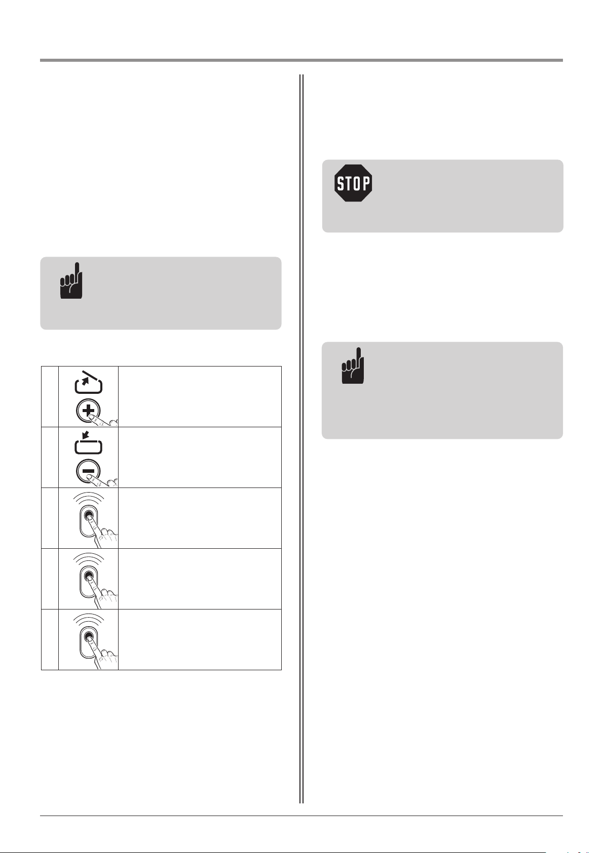
1.
After pressing the (+) button:
The gate must open and travel to the
saved OPEN end position.
2.
After pressing the (–) button:
The gate must close and travel to the
saved CLOSED end position.
3.
After pressing the hand transmitter
button: The operator system must move
the gate in either the OPEN or CLOSE
direction.
4.
After pressing the hand transmitter
button while the operator system is
running:
The operator system must stop.
5.
When the button is pressed again,
the operator system moves in the
opposite direction.
8.5 Function test
8.5.1 Learning run for soft-run
Test:
Advice:
The parameter settings are still saved
if the power supply is disconnected.
Only a reset causes the driving power
settings for the OPEN and CLOSE
directions to revert to the factory
settings.
Advice:
After a disconnection of the power
supply, the soft run must be reactivated
with two complete runs between the
door positions OPEN and CLOSED.
36 Manual for installation and operation, Comfort 515 GB (#87458)
Page 37
9. Extended operator functions
9.1 General notes on extended operator functions
Advice:
The MASTER and SLAVE controls must
be programmed independently of one
another.
Take care to observe the programming
settings of the individual menus.
Additional functions can be programmed for the
operator system using the extended functions.
The programming facility is divided into three areas:
Area 1: Levels
The adjustable functions have been grouped in
8 levels according to the type of function.
Each level can have up to 8 menus.
The (+) and (-) buttons are used to scroll through
the selections within the levels.
Levels that are not used are displayed but cannot be
opened.
Levels-Exit switches from programming to operating
mode.
Ar ea 2: Menu
Each menu sets one parameter.
The (+) and (-) buttons are used to scroll through
the settings within the menus.
Menus that are not in use are skipped over and are
not displayed.
You can return to the first level via Menu-Exit.
Reference:
- All the available levels and menus are
described in the overview of the
programmable functions (Section 9.3).
- The messages are explained in
Section 10.
i
Caution!
Important factory default settings can
be changed using the extended
functions.
All the parameters must be set correctly
to avoid damage to persons or property.
Area 3: Parameters
Each function has a maximum of 16 settings.
The (+) and (-) buttons are used to scroll through
the settings for the adjustable parameters.
Parameters that cannot be adjusted are skipped over
and not displayed.
It is not possible to overshoot by pressing the
(+) and (-) buttons.
Pressing the (P) button saves the parameters you
have set.
End Programming
The programming session can be ended in two ways:
1. Via Levels-Exit by pressing the (P) button.
The controls then switch to operating mode.
2. By pressing the (P) button for longer than 5 seconds
at any time and from any area.
The controls then switch to operating mode.
If a parameter had been changed, it will be saved in
the process.
When the programming session ends, all the LEDs light
up and then go out one after the other, in sequence
from 8 to 1.
If no buttons are pressed within 120 seconds while in
programming mode, the controls revert to operating
mode.
A corresponding message is displayed.
Manual for installation and operation, Comfort 515 GB (#87458) 37
Page 38
9. Extended operator functions
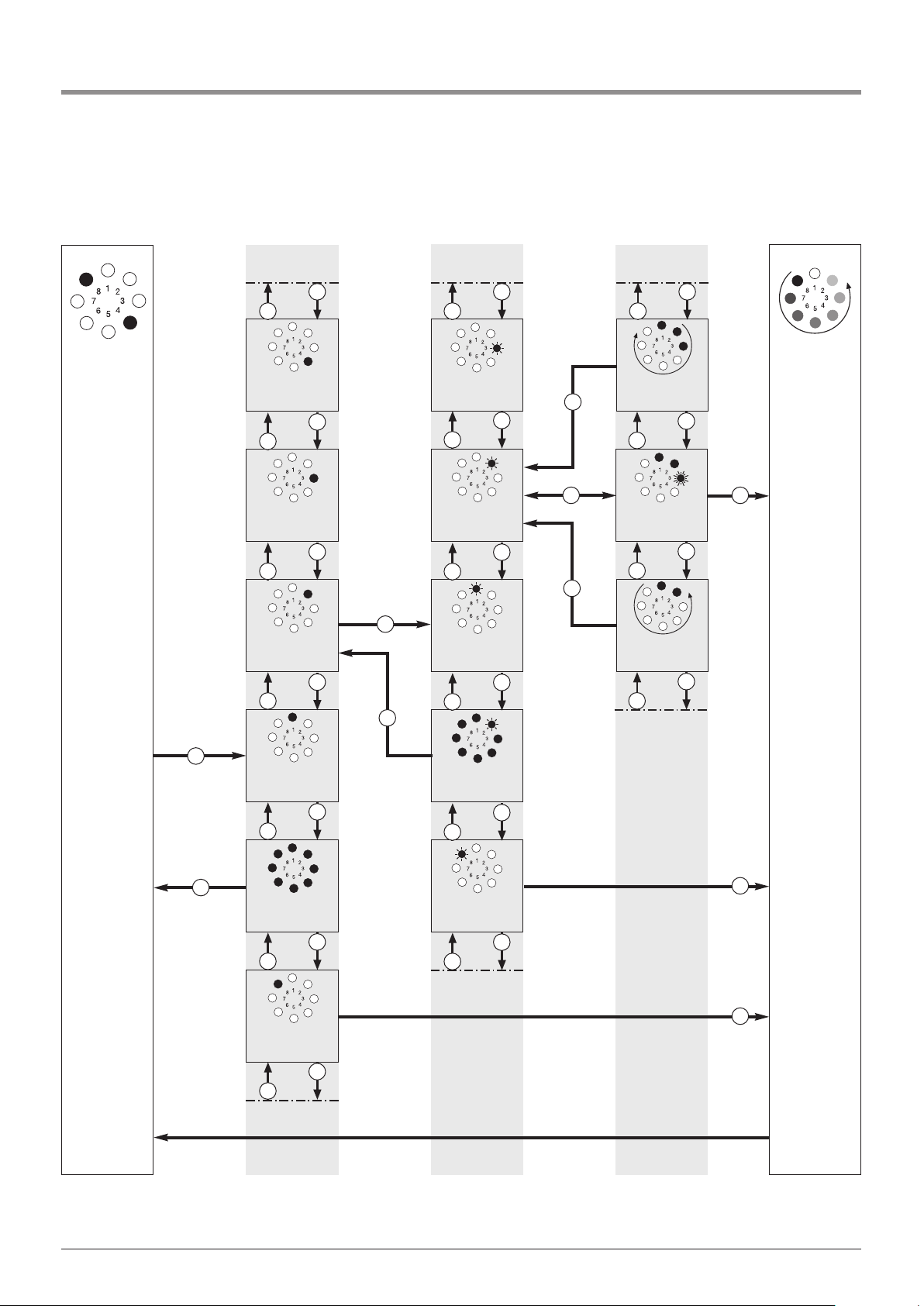
9.2 Programming structure for extended operator functions (Example for Level 2, Menu 2)
End
programming
ParameterMenüLevels
Level 3
Level 4
Menu 3
Higher value
Menu 2
Menu 1
Menu-Exit
(Level 2)
Level 2
Level 1
Levels-Exit
Level 8
> 10 sec.
Menu 8
Lower value
Parameter
Operating
mode
+
-+-+-+-
P
+
-
+-+-+-+
-
PPP
> 5 sec.
P
+-+-+
-
PPP
+
-
+
-
+
-+-+-
> 5 sec.
P
> 5 sec.
P
38 Manual for installation and operation, Comfort 515 GB (#87458)
Page 39
9. Extended operator functions
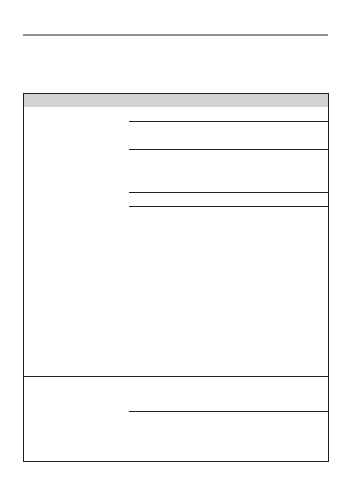
9.3 General overview of the programmable functions
Manual for installation and operation, Comfort 515 GB (#87458) 39
Level Menu Factory default setting
Level 1 – Basic functions
Menu 7: Relay output Signal light
Menu 8: RESET No reset
Level 2 – Operator settings
Menu 1: Required driving power OPEN Setting 5
Menu 2: Required driving power CLOSE Setting 5
Level 3 – Automatic closing timer
Menu 1: Automatic closing timer Deactivated
Menu 3: Gate open duration 15 seconds
Menu 4: Warning time 5 seconds
Menu 5: Start-up warning 0 seconds
Menu 7: Signal light
Door movement / warning:
light flashes
Door stationary:
light is off (energy-saving)
Level 4 – Remote programming Menu 2: Active wing –
Level 5 – Special function
Menu 1: Programmable impulse input
Active wing /
Impulse (OPEN/STOP/CLOSE)
Menu 2: Start delay for second motor unit 2 seconds
Menu 4: Lighting duration 180 seconds
Level 6 - Variable speed
Menu 1: Speed OPEN Setting 16
Menu 2: Soft run speed OPEN Setting 8
Menu 4: Speed CLOSE Setting 16
Menu 6: Soft run speed CLOSE Setting 8
Level 8 – System settings
Menu 1: Photocell Operation without photocell
Menu 2: Closing edge safety device
Gate reverses a little
(OPEN/CLOSE)
Menu 4: Operating modes
Press-and-release
(OPEN/CLOSE)
Menu 5: Function of the direction command transmitters Not active
Menu 6: Function of the impulse command transmitters Stop function active
Page 40
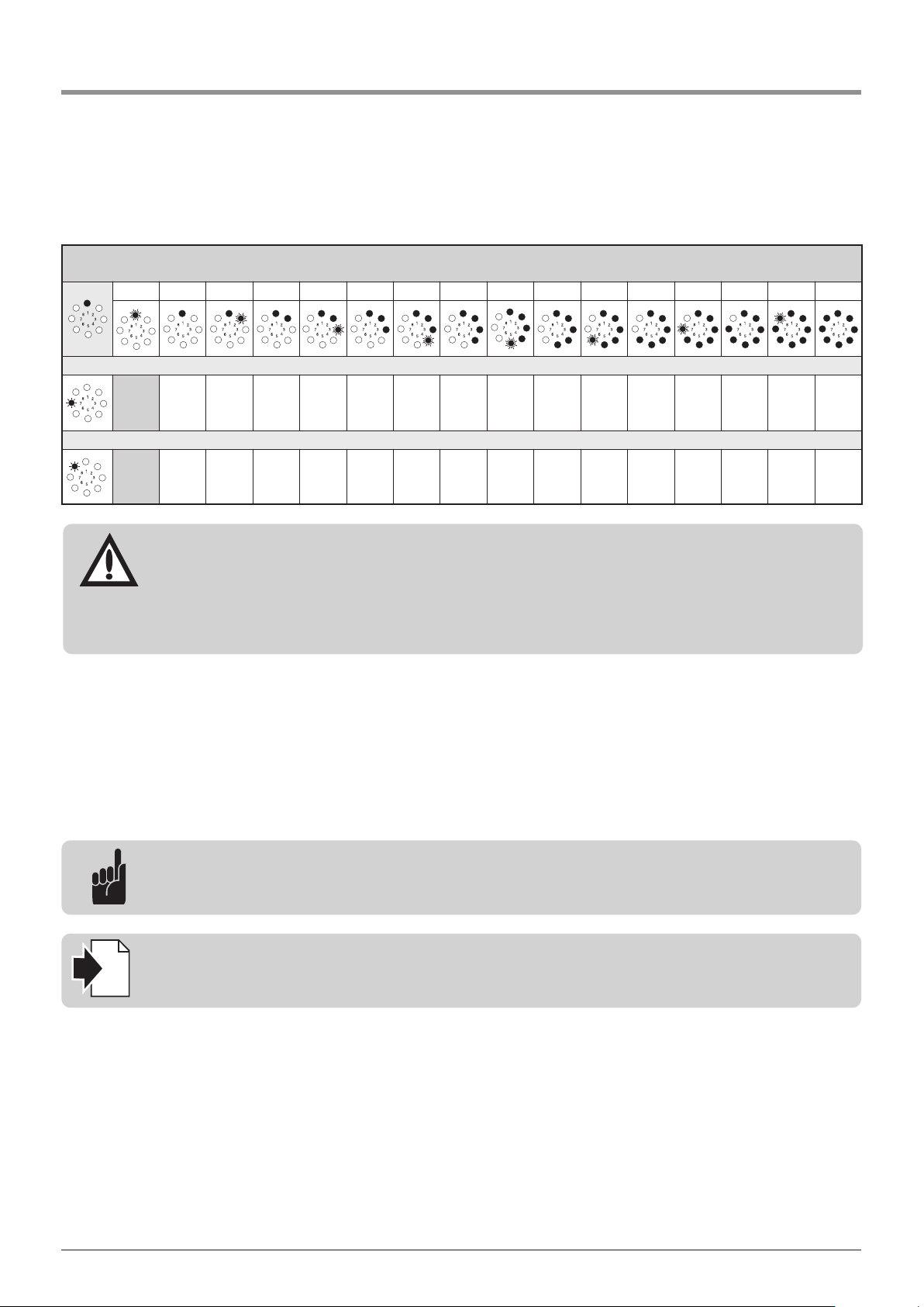
9. Extended operator functions
9.4 Functions overview for the levels
Attention!
After a reset, all the parameters revert to the factory settings.
In order to guarantee the proper operation of the MASTER and SLAVE controls:
- all the required functions must be re-programmed,
- the remote control unit must be re-programmed,
- the MASTER and SLAVE motor units must be driven to the OPEN and CLOSED positions once.
Level 1 – Basic functions
1 2 3 4 5 6 7 8 9 10 11 12 13 14 15 16
Menu 7: Relay output – terminal 16/17 (MASTER only)
A7 B7 C7 D7 E7 F7 G7 H7 – – – – – – – –
Menu 8: RESET (MASTER + SLAVE)
No Yes – – – – – – – – – – – – – –
Advice:
If the automatic closing function (Level 3 / Menu 1) is activated, the relay output (Level 1 / Menu 7) can
be reprogrammed if required.
A7 Signal light
B7 Gate position OPEN
C7 Gate CLOSED position
D7 Intermediate position OPEN
E7 Intermediate position CLOSED
F7 Motor starts (wiping impulse – 1 second)
G7 Fault
H7 Lighting
Menu 7: Relay output
Reset
• Reset the SLAVE controls first and complete the controls test.
• Then reset the MASTER controls.
For a different sequence, the control unit must be disconnected from the mains and then switched on again.
40 Manual for installation and operation, Comfort 515 GB (#87458)
Reference:
- The function of the signal light (A7) can be adjusted in level 3, menu 7.
- The lighting function (H7) is set in Level 5, Menu 4.
i
Page 41
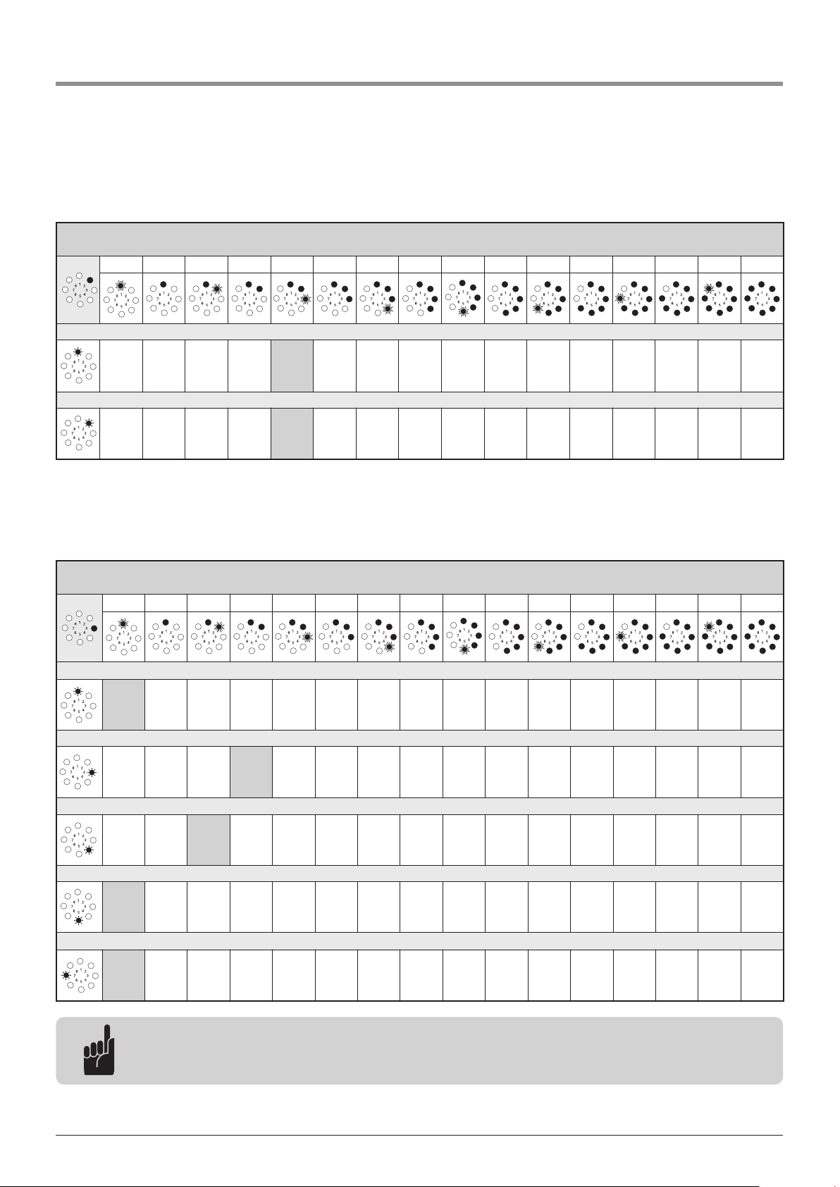
9. Extended operator functions
Level 2 – Operator settings
1 2 3 4 5 6 7 8 9 10 11 12 13 14 15 16
Menu 1: Required driving power OPEN (sensitivity on a scale from 1 to 16*) (MASTER + SLAVE)
1 2 3 4 5 6 7 8 9 10 11 12 13 14 15 16
Menu 2: Required driving power CLOSE (sensitivity on a scale from 1 to 16*) (MASTER + SLAVE)
1 2 3 4 5 6 7 8 9 10 11 12 13 14 15 16
*The higher the setting, the higher the driving power.
Manual for installation and operation, Comfort 515 GB (#87458) 41
Advice:
- The automatic closing timer can only be programmed if a photocell barrier is connected.
- The functions in Menu 1 can be altered as desired via the time settings in Menus 3 and 4.
Level 3 - Automatic closing timer
1 2 3 4 5 6 7 8 9 10 11 12 13 14 15 16
Menu 1: Automatic closing timer (MASTER only)
A1 B1 C1 D1 E1 F1 G1 H1 – – – – – – – –
Menu 3: Gate open duration (in seconds) (MASTER only)
2 5 10 15 20 25 30 35 40 50 80 100 120 150 180 255
Menu 4: Warning time (in seconds) (MASTER only)
1 2 5 10 15 20 25 30 35 40 45 50 55 60 65 70
Menu 5: Start-up warning (in seconds) (MASTER only)
0 1 2 3 4 5 6 7 – – – – – – – –
Menu 7: Signal light
A7 B7 C7 D7 E7 F7 – – – – – – – – – –
Page 42
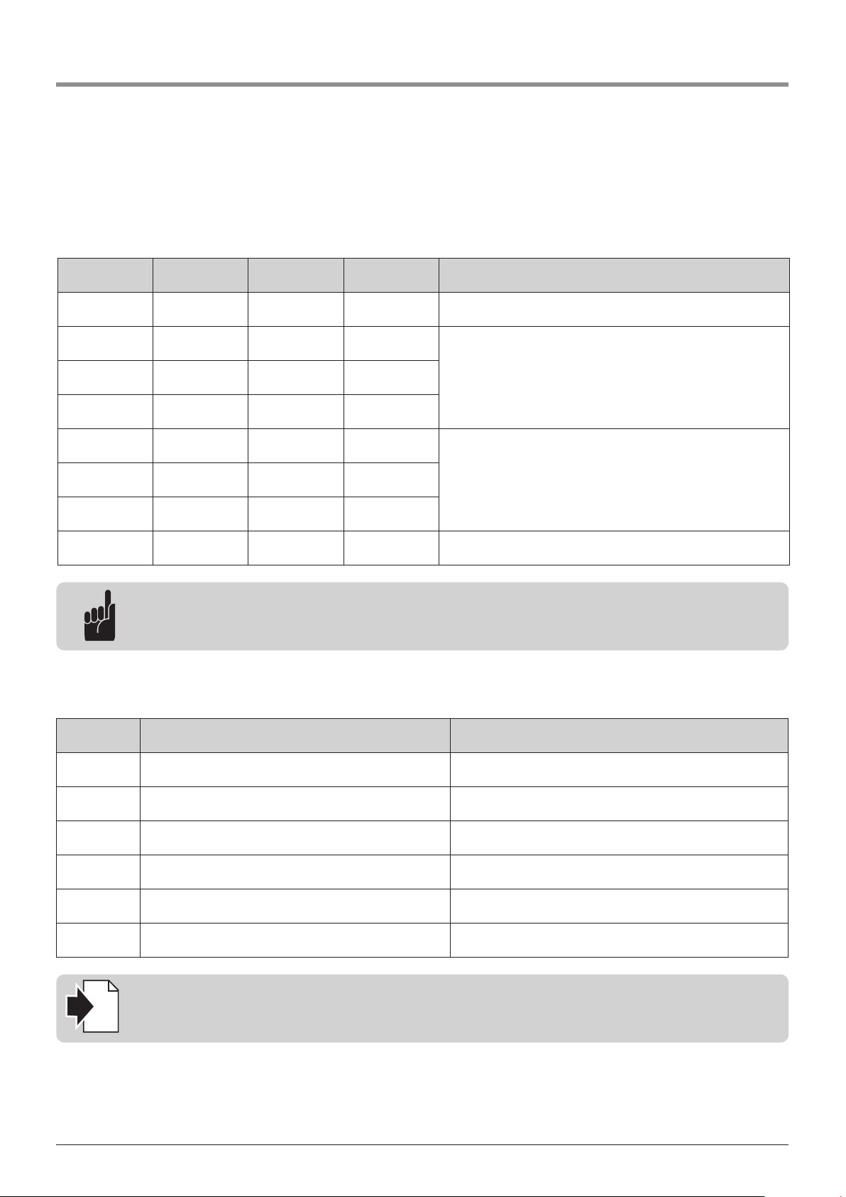
9. Extended operator functions
42 Manual for installation and operation, Comfort 515 GB (#87458)
Menu 1: Automatic closing timer
Setting
Gate open
duration
Warning time
Automatic
closing timer
other functions
A1 - - deactivated -
B1 15 5 activated
Renewal (restart) of the gate open duration after the photocell
barrier has been driven past
C1 30 5 activated
D1 60 8 activated
E1 15 5 activated
Interruption of the gate open duration after the photocell bar-
rier has been driven past
F1 30 5 activated
G1 60 8 activated
H1 unlimited 3 activated
Closes after the photocell barrier has been driven past / closing
prevention
Advice:
Without a connected photocell or closing prevention device, only parameter A1 can be adjusted.
Menu 7: Signal light
Setting Gate movement / Warning Gate stoppage
A7 flashing OFF (Electricity saving)
B7 lighting OFF (Electricity saving)
C7 flashing flashing
D7 lighting lighting
E7 flashing lighting
F7 lighting flashing
Reference:
The signal light connection can be adjusted in level 1, menu 7.
i
Page 43
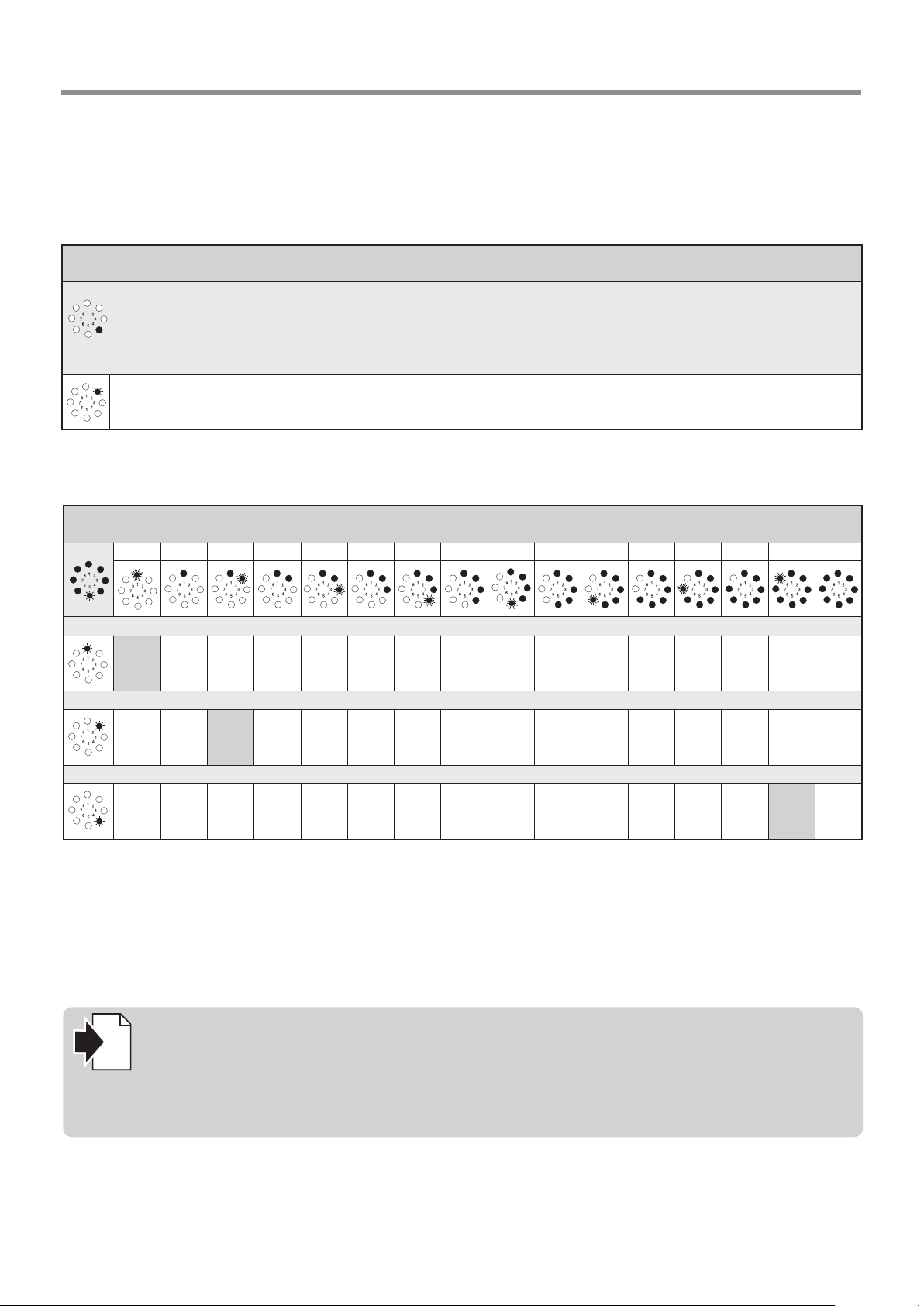
9. Extended operator functions
Manual for installation and operation, Comfort 515 GB (#87458) 43
Level 4 – Remote programming
Menu 2: Active wing – remote impulse to operate one gate wing only (MASTER ONLY)
LED 7 flashes slowly -> press hand transmitter button -> LED 7 flashes quickly
Level 5 – Special function
1 2 3 4 5 6 7 8 9 10 11 12 13 14 15 16
Menu 1: Programmable impulse input - XB99 (MASTER ONLY)
A1 B1 – – – – – – – – – – – – – –
Menu 2: Start-delay for second motor unit (in seconds) (MASTER ONLY)
A2 B2 C2 D2 E2 F2 G2 H2 I2 J2 K2 L2 M2 N2 O2 P2
Menu 4: Lighting duration (in seconds) – Terminal 16/17
2 5 10 15 20 25 30 35 40 50 80 100 120 150 180 255
A1 Connection option 1:
Terminal B9/3: Active wing
Terminal B9/8: Impulse (OPEN/STOP/CLOSE)
B1 Connection option 2:
Terminal B9/3: Direction command transmitter, CLOSE
Terminal B9/8: Direction command transmitter, OPEN
Menu 1: Programmable impulse input
Reference:
The programming of the special function is dependent on terminal XB99.
Terminal XB99 is described in Section 6.6.
The programmed lighting time is only active if the relay output (Level 1 / Menu 7) is set to
“Lighting” (H7).
i
Page 44
9. Extended operator functions
44 Manual for installation and operation, Comfort 515 GB (#87458)
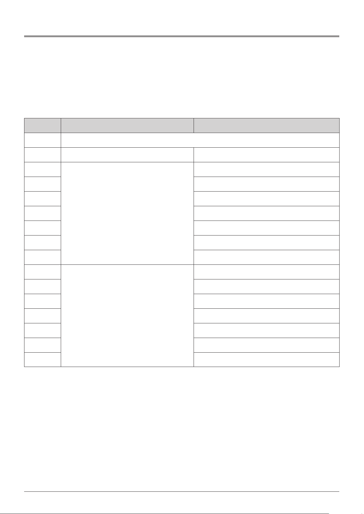
Menu 2: Start-delay for second motor unit (in seconds) (MASTER ONLY)
Separate adjusting facilities for OPEN and CLOSE direction of travel (in seconds)
Setting OPEN direction CLOSE direction
A2 Deceleration deactivated
B2 1 1
C2
2
2
D2 3
E2 4
F2 5
G2 6
H2 10
I2 15
J2
3
3
K2 4
L2 5
M2 6
N2 10
O2 15
P2 20
Page 45
Manual for installation and operation, Comfort 515 GB (#87458) 45
9. Extended operator functions
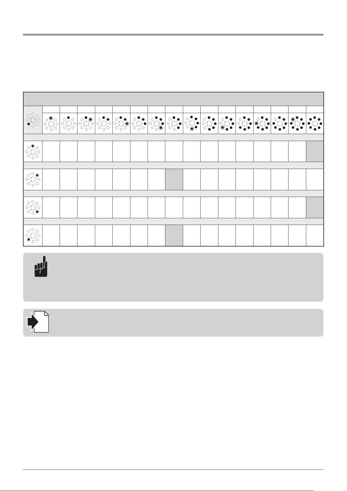
Level 6 - Variable speed
1 2 3 4 5 6 7 8 9 10 11 12 13 14 15 16
Menu 1: Speed OPEN (in increments) (MASTER + SLAVE)
– – – – – – 7 8 9 10 11 12 13 14 15 16
Menu 2: Soft run speed OPEN (in increments) (MASTER + SLAVE)
– – – – 5 6 7 8 9 10 11 12 13 14 15 16
Menu 4: Speed CLOSE (in increments) (MASTER + SLAVE)
– – – – – – 7 8 9 10 11 12 13 14 15 16
Menu 8: Soft run position CLOSED (MASTER + SLAVE)
– – – – 5 6 7 8 9 10 11 12 13 14 15 16
Reference:
If changes are made in Menus 1, 2, 4 and 6 in Level 6, a new performance check must be carried out
(Section 8.6).
i
Advice:
The operation speed must be set higher than the soft run speed.
After altering the driving speed, the system must be disconnected from the mains once when in the
CLOSED position.
After switching on and a learning run to the OPEN and CLOSED door positions has been carried out,
the drive system is ready for operation.
Page 46
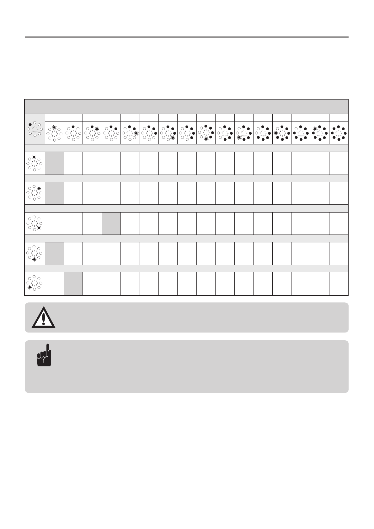
46 Manual for installation and operation, Comfort 515 GB (#87458)
9. Extended operator functions
Level 8 – System settings
1 2 3 4 5 6 7 8 9 10 11 12 13 14 15 16
Menu 1: Photocell
A1 B1 C1 D1 E1 F1 G1 H1 I1 J1 – – – – – –
Menu 2: Closing edge safety device
A2 B2 C2 D2 – – – – – – – – – – – –
Menu 4: Operating modes
A4 B4 C4 D4 – – – – – – – – – – – –
Menu 5: Function of the direction command transmitters
A5 B5 – – – – – – – – – – – – – –
Menu 6: Function of the impulse command transmitters
A6 B6 – – – – – – – – – – – – – –
Attention!
If a photocell is connected, it is automatically recognised by the controls after MAINS ON.
The photocell can be reprogrammed later.
Advice:
Photocells and closing edge safety devices that are not required must be disconnected, or the controls
will recognise them. Disconnected closing edge safety devices must be replaced with an 8.2 kΩ resistance.
If an external photocell is connected at terminals B9 and 34, the power supply must be switched off
and on again before programming the automatic closing timer.
Page 47
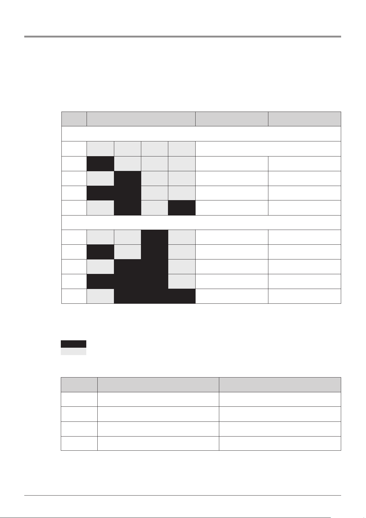
Manual for installation and operation, Comfort 515 GB (#87458) 47
9. Extended operator functions
Menu 1: Photocell
Photocells Gate movement, OPEN Gate movement, CLOSE
2-wire photocells
A1 A B C D Operation without photocell
B1 A B C D Gate stops not active
C1 A B C D not active Gate reverses completely
2
D1 A B C D Gate stops Gate reverses completely
2
E1 A B C D not active Gate reverses completely
2
2-wire photocells and photocells with potential-free relay contacts
F1 A B C D not active Gate reverses completely
2
G1 A B C D Gate stops Gate reverses completely
2
H1 A B C D not active Gate reverses completely
2
I1 A B C D Gate stops Gate reverses completely
2
J1 A B C D not active Gate reverses completely
2
A Photocell OPEN (terminal XP62B)
B Photocell CLOSE1 (terminal XP62A)
C Photocell at terminals B9 and 34 (only in CLOSE direction)
D Photocell CLOSE2 (terminal XP62B)
Photocell active
Photocell not active
Gate movement, OPEN Gate movement, CLOSE
A2 Gate reverses a little
1
Gate reverses a little
1
B2 Gate reverses a little
1
Gate reverses completely
2
C2 Gate reverses completely
2
Gate reverses a little
1
D2 Gate reverses completely
2
Gate reverses completely
2
Menu 2: Closing safety edge device
Page 48
48 Manual for installation and operation, Comfort 515 GB (#87458)
9. Extended operator functions
Menu 4: Operating modes
Menu 5: Function of the direction command transmitter
Menu 6: Function of the impulse command transmitter
1
Gate reverses a little: The drive system moves the gate a short distance in the opposite
direction in order to free an obstacle.
2
Gate reverses completely: The drive system moves the gate to the opposite end position.
OPEN CLOSE
A4 press and hold press and hold
B4 automatic closing press and hold
C4 press and hold automatic closing
D4
automatic closing automatic closing
Direction command transmitters Explanations
A5 not active
The direction command transmitters only give a command
when the gate is stationary.
B5 STOP only
A moving gate is stopped by every direction command
transmitter.
Impulse command transmitters Explanations
A6 not active
The impulse command transmitters only give a command
when the gate is stationary.
B6 STOP only, then standard sequence
A moving gate is stopped by every impulse command
transmitter. The next command starts the drive system
running in the opposite direction
(OPEN - STOP - CLOSE - STOP - OPEN).
Page 49
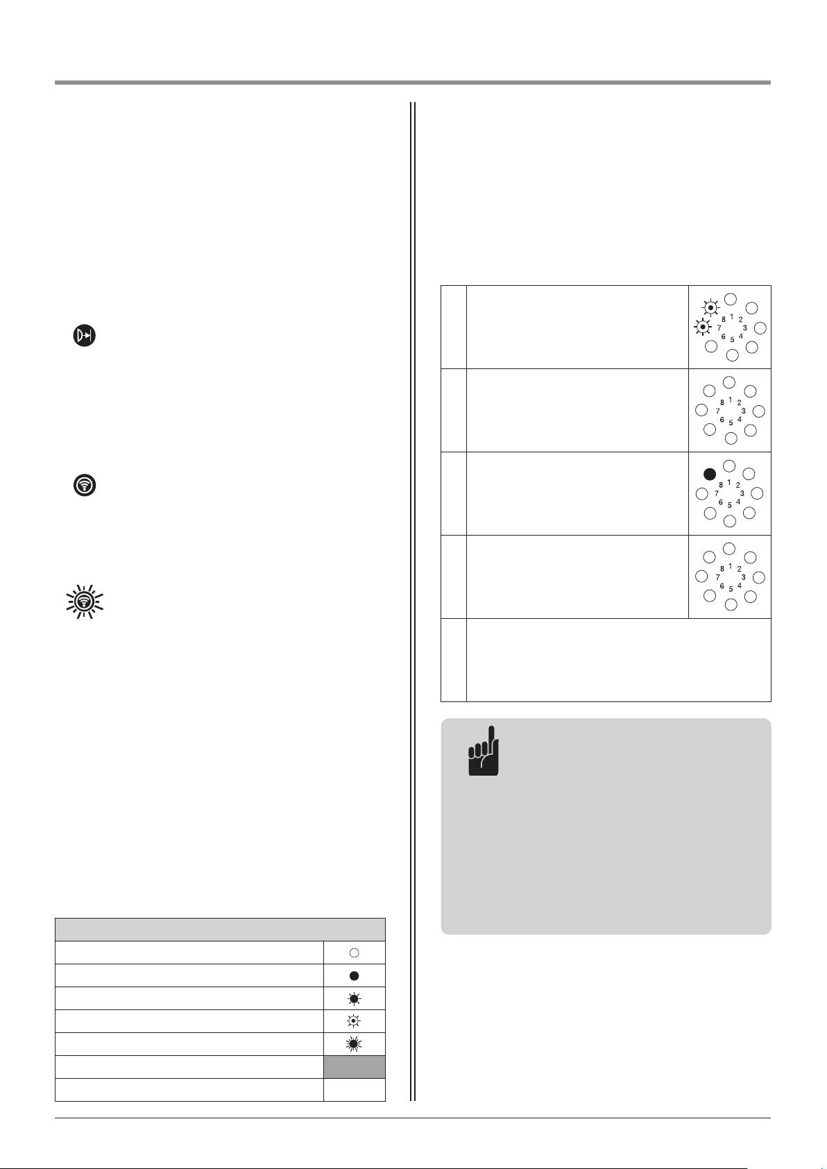
Manual for installation and operation, Comfort 515 GB (#87458) 49
In addition to messages regarding the gate position,
status messages give information regarding the status
of the operator system during operation.
Safety elements:
During operation LED 1 serves as a status
indicator for the safety elements connected
(closing edge safety device, photocell).
If the safety element in question is triggered,
LED 1 lights up whilst it is activated.
Control elements / remote controls:
During operation and when carrying out
component tests, LED 7 serves as a status
indicator for the control elements connected
(OPEN, CLOSE, STOP, half OPEN, etc.).
If the control element in question is triggered,
LED 7 lights up whilst it is activated.
If a remote signal is received, LED 7 flashes
quickly.
10.1 Status messages
Legend:
LED off
LED on
LED flashes slowly
LED pulses
LED flashes quickly
Factory default setting
Not possible –
1.
Message number is displayed for
approx. 3 seconds
(example: Message 15).
2.
Pause between messages for
approx. 1 second.
3.
Operating mode is displayed for
approx. 3 seconds
(example: operating voltage).
4.
Pause between messages for
approx. 1 second.
5.
Messages 1 to 4 are repeated.
Malfunctions in the system are indicated by a
corresponding message number.
The controls switch to message mode.
Advice:
- The controls show the message
numbers via one or more rhythmically
flashing LEDs.
The message number is found by
adding together the numbers next to
the flashing LEDs.
- During programming, all status
messages and other messages are
suppressed. The messages in
programming mode are always
unambiguous.
10.2 Fault messages
10. Messages
Page 50
50 Manual for installation and operation, Comfort 515 GB (#87458)
10. Messages
The message numbers serve two purposes:
1. They indicate why the controls were unable to
carry out the drive command given.
2. They indicate which components are faulty.
This facilitates better and faster service on site,
and only the control components identified as
being faulty need be replaced.
The controls remain in message mode until they switch
to operating mode or diagnostic mode.
Switching to operating mode
The controls switch to operating mode as soon as they
receive a movement impulse.
Switching to diagnostic mode
The controls can be switched to diagnostic mode from
either message mode or operating mode.
• Give the (P) button a short press.
The controls switch to diagnostic mode and display the
last fault.
Page 51
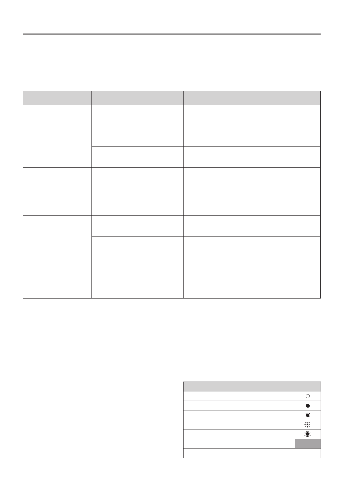
Manual for installation and operation, Comfort 515 GB (#87458) 51
10. Messages
10.3 Rectifying faults
Error Cause Solution
LED 8 does not light up. - No voltage. - Check that the mains power supply is operational.
- Check the connection to the mains power supply.
- Thermal overload protection in power
transformer was activated.
- Allow the power transformer to cool down.
- Defective control unit. - Have the operator system checked.
No reaction on impulse. - The connection terminals for the
“impulse” button were by-passed,
e.g. due to a short-circuit or flattened
terminals.
- Try temporarily disconnecting any key switches or interior
push buttons that are connected to the control unit
(Section 6.6):
Remove the lead from socket XB99 and then bridge
terminals B9 and 5; insert jumper plug and check for
cabling errors.
No reaction on impulse from
hand transmitter.
- Module antenna is not plugged in. - Connect the module antenna to the control unit
(Section 8.1).
- The hand transmitter coding does not
correspond to the receiver coding.
- Activate hand transmitter again (Section 8.4.3).
- Hand transmitter battery is empty. - Insert new battery (Section 7.1).
- Defective hand transmitter, control
unit electronics or module antenna.
- Have all 3 components checked.
10.3.1 Malfunctions without error messages
Legend:
LED off
LED on
LED flashes slowly
LED pulses
LED flashes quickly
Factory default setting
Not possible –
Page 52
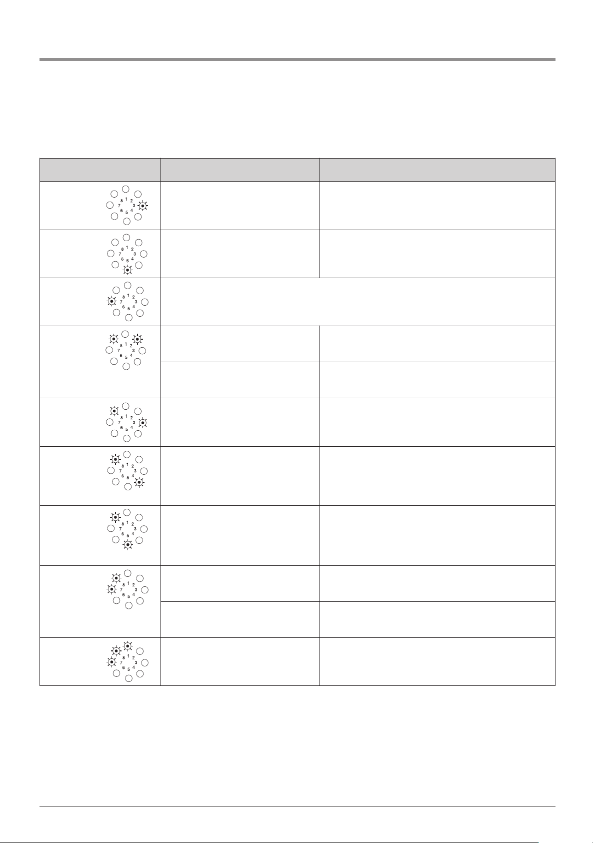
52 Manual for installation and operation, Comfort 515 GB (#87458)
Error Cause Solution
Message 3 - Closing edge safety device OPEN was
activated.
- Remove the obstacle or have the closing edge safety device
checked.
- Deactivate or connect the closing edge safety device.
Message 5 - Closing edge safety device CLOSE was
activated.
- Remove obstacle or have the closing edge safety device
checked.
- Deactivate or connect the closing edge safety device.
Message 7 - If no buttons are pressed within 120 seconds, the programming mode terminates automatically.
Message 10 - Gate movement too stiff.
- Gate blocked.
- Ensure that the gate moves easily.
- Maximum driving power setting is too
low.
- Have the max. driving power (Section 9.4 / Level 2 /
Menu 1+2) checked by an expert.
Message 11 - Excess travel stop. - Have the operator system checked.
Message 12 - CESD test in OPEN direction not OK. - Check closing edge safety device.
- Programme out the closing edge safety device if there is no
CESD present (Section 9.4 / Level 8 / Menu 2).
- Reinsert an 8.2 kOhm resistance.
Message 13 - CESD test in CLOSED direction not OK. - Check closing edge safety device.
- Programme out the closing edge safety device if there is no
CESD present (Section 9.4 / Level 8 / Menu 2).
- Reinsert an 8.2 kOhm resistance.
Message 15 - External photocell interrupted or
defective.
- Remove obstacle or have the photocell checked.
- Programmed for photocell, but no
photocell is connected.
- Deactivate or connect the photocell.
Message 16 - Power sensor for the automatic
cut-out is defective.
- Have the motor unit checked.
10.3.2
Malfunctions with error messages
10. Messages
Page 53
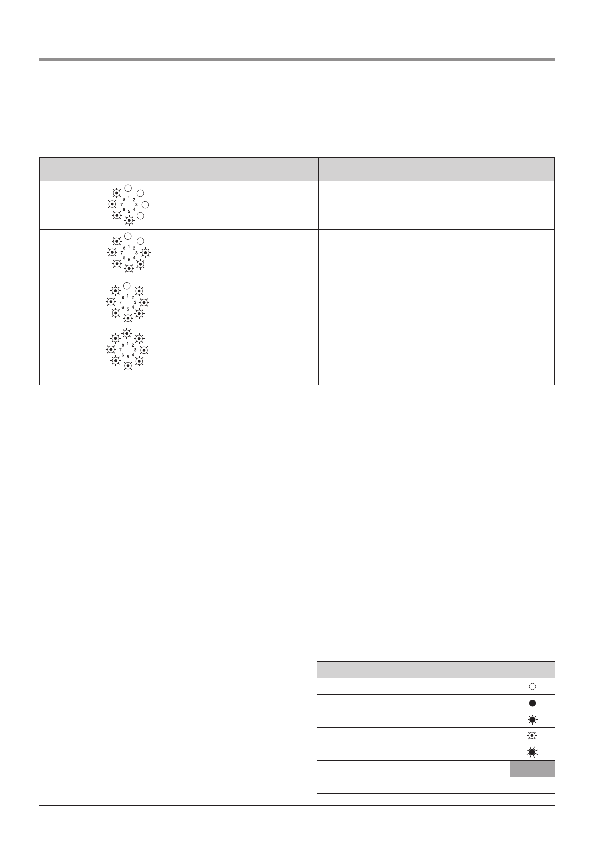
Manual for installation and operation, Comfort 515 GB (#87458) 53
10. Messages
Error Cause Solution
Message 26 - Undervoltage, operator system
overloaded at maximum power
setting, 16.
- Have the external power supply checked.
Message 33 - Rise in temperature due to
overheating.
- Allow the motor unit to cool down.
Message 35 - Electronics are defective. - Have the operator system checked.
Message 36 - Wire jumper removed, but stop button
not connected.
- Connect stop button or wire jumper B9/5 (Section 6.6).
- Closed circuit interrupted. - Lock the operator system.
Legend:
LED off
LED on
LED flashes slowly
LED pulses
LED flashes quickly
Factory default setting
Not possible –
Page 54
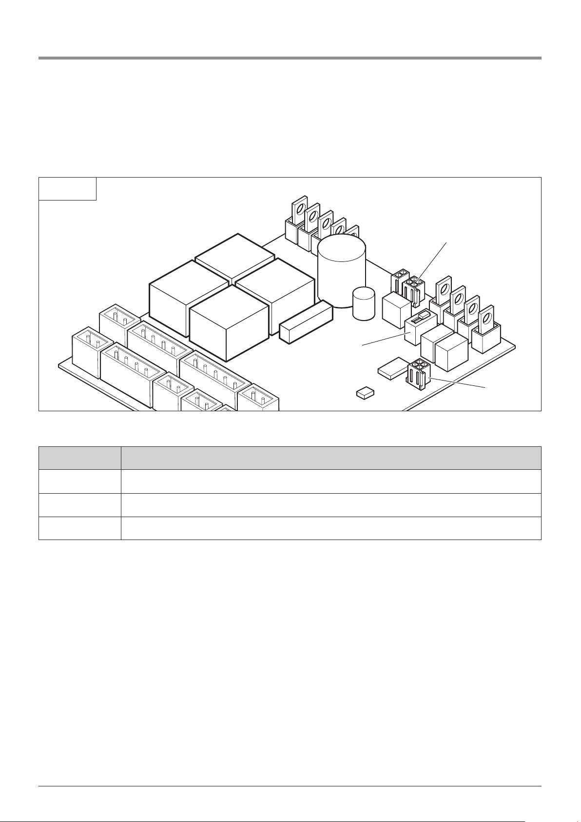
54 Manual for installation and operation, Comfort 515 GB (#87458)
Designation Description
A DIP switch ON/OFF for the stop circuit plug B (hinged gate stop circuit ON)
B Connection of release mechanism - sliding gates only
C Connection of extension module for potential-free limit switch
Expansion module legend
11.1 Connection diagram Comfort 515
11.1 / 1
A
B
C
Expansion module
11. Attachment
Page 55
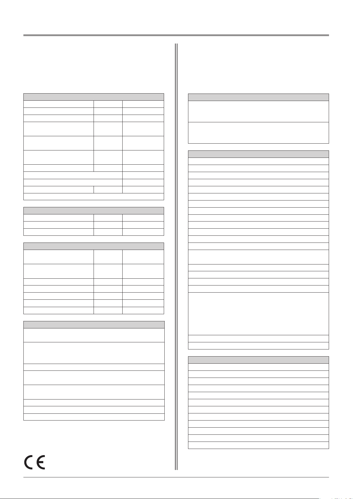
Manual for installation and operation, Comfort 515 GB (#87458) 55
11. Attachment
11.2 Technical Data for Comfort 515
Electrical data
Voltage rating *) V 120 / 230 / 260
Rated frequency Hz 50 / 60
Current input A 1,0
Power consumption in
operation
KW 0,2
Power consumption on
standby
W 1
Operating mode
(connection period)
Min. KB 8
Controls voltage V DC 24
Protection category for motor unit IP 44
Protection category for controls IP 65
Protection class II
*) For country-specific version: see type plate
Mechanical data
Max. push and pull force N 1,000
Travel speed mm/sec. 15–20
Opening phase (specific to gate) sec. approx. 15–25
General data
Motor unit dimensions
Short version
mm 120x200x780
Motor unit dimensions
Long version
mm 120x200x980
Dimensions of controls mm 120x240x100
Weight (single-wing system) kg 11,20
Weight (double gate system) kg 18,00
Weight of controls kg 2,50
Temperature range °C -20 to +60
Features / Safety functions
Electricity saving technology x
Safety limit switch – technical systems x
Soft start, soft stop x
Excess travel stop x
Lockable uncoupling system x
Connections for push-buttons, code buttons and key switches x
Connections for photocell, gate travelling directions OPEN and CLOSE x
Connection for signal light 24 V DC x
Connection of gate position message system x
Connection of extension module for gate position message system x
Connection for closing edge safety device OPEN and CLOSE 8.2 kΩ x
Connection for electric lock 24 V DC x
Integrated evaluation 8.2 kΩ x
Automatic cut-out OPEN and CLOSE, can be
programmed separately x
Programmable active wing function x
Gate travelling speed can be programmed x
Soft run speed OPEN and CLOSE can be programmed separately x
Automatic closing function x
Retrofit measures for potential-free signal relay
possible, for: - Signal light
- Wiping impulse
- 3 minute lighting
- Travel limit message
- Error message x
Fault signalling x
Reset function x
Accessories
Multibit remote control x
Modular antenna, 868 MHz, IP 65 x
Signal light 24 V DC x
Closing edge safety device 8.2 kΩ x
Photocell x
Electric lock x
Transponder system x
Key switch x
Code button x
Interior push button x
Signal light relay retrofit kit 24 V DC x
Expansion module x
Supply package **)
Motor unit Comfort 515
with motor supply cable (1.5 m)
Motor unit Comfort 515
(for double gate systems only)
with motor supply cable (8.5 m)
Separate control unit, Control x.51
Multibit remote control, 315 / 433 / 868 MHz,
incl. Digital 304 Mini Hand Transmitter, 4-channel *)
Mounting brackets:
gate and post brackets
Fixing materials for controls and motor unit
*) For country-specific version: see type plate
**) subject to country-specific alternations
Application
Comfort 515 up to 200 kg
- gate wing 2.5 m tall x 2.5 m wide,
max. 50% infill area
Comfort 515 L up to 200 kg
- gate wing 2.5 m tall x 3.5 m wide,
max. 50% infill area
Page 56
56 Manual for installation and operation, Comfort 515 GB (#87458)
11. Attachment
11.3 Manufacturer’s Declaration
11.4 EC Declaration of Conformity
We herewith declare that the product sold by us
and mentioned below corresponds in its design,
construction and version to the relevant and basic
safety and health requirements of the following
EC regulations: EMC Directive, Machinery Directive
and Low Voltage Directive.
Product changes made without our consent will render
this Declaration void.
Product: Comfort 515
Relevant EC Regulations:
- EC EMC Directive (89/336/EWG),
- Machinery Directive
(98/37/EG) and
- Low Voltage Directive
(73/23/EWG and 93/68/EWG).
Applied harmonised standards, in particular:
EN 292-1
EN 61000-6-2
EN 61000-6-3
EN 55014
EN 61000-3-2
EN 61000-3-3
EN 60335-1
EN 60335-2-103
EN 12445
EN 12453
EN 300220-1
EN 301489-3
ETS 300683
02.01.2008 pp K. Goldstein
Marantec Antriebs- und Steuerungstechnik GmbH & Co. KG
Remser Brook 11 · 33428 Marienfeld · Germany
Telephone +49 (52 47) 7 05-0
We herewith declare that the product sold by us
and mentioned below corresponds in its design,
construction and version to the relevant and basic
safety and health requirements of the following
EC regulations: EMC Directive, Machinery Directive
and Low Voltage Directive.
Product changes made without our consent will render
this Declaration void.
Product:
Relevant EC Regulations:
- EC EMC Directive (89/336/EWG),
- Machinery Directive
(98/37/EG) and
- Low Voltage Directive
(73/23/EWG and 93/68/EWG).
Applied harmonised standards, in particular:
EN 292-1
EN 61000-6-2
EN 61000-6-3
EN 55014
EN 61000-3-2
EN 61000-3-3
EN 60335-1
EN 60335-2-103
EN 12445
EN 12453
EN 300220-1
EN 301489-3
ETS 300683
Date / Signature
Page 57

Manual for installation and operation, Comfort 515 GB (#87458) 57
Page 58

Version: 11.2008
#87 458
1 - GB 360252 - M - 0.5 - 0805
English Copyright.
No part of this manual may be reproduced without our prior consent.
Subject to changes which are in the interest of technical improvements.
87458
 Loading...