

Marantec 500 Series User Manual
GB
Operating instructions
Last updated: 04.2016
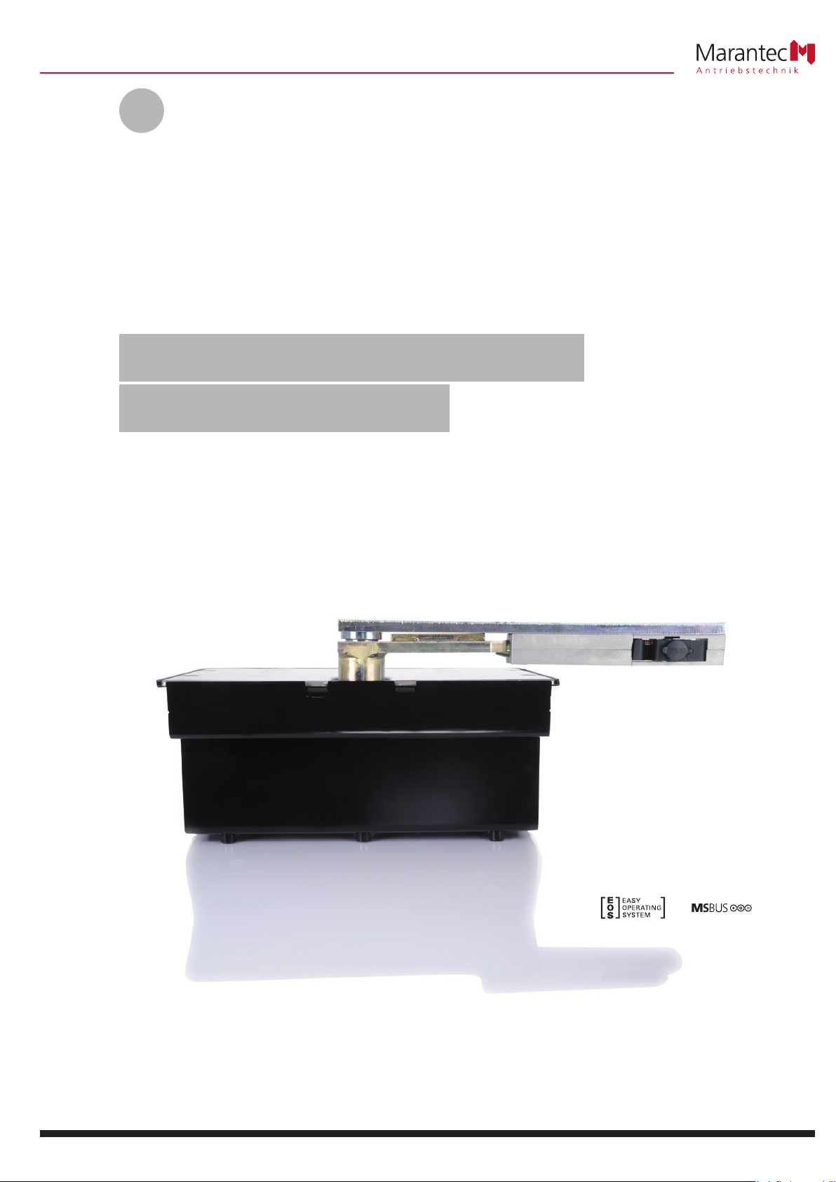
Motor unit for hinged gates
Comfort 585, 586
Table of Contents
DANGER!
Regarding this document
1. General safety instructions .....................3
1.1 Intended use ................................3
1.2 Target group ................................3
1.3 Warranty ...................................3
2. Scope of supply ..............................4
3. Gate system .................................4
4. Installation ..................................5
4.1 Preparing for installation .......................5
4.2 Foundation layout ............................6
4.3 Installing the operator housing. . . . . . . . . . . . . . . . . . . 6
4.4 Installing the gate wing ........................8
4.5 Installing the motor unit .......................9
4.6 Installing the release mechanism .................9
4.7 Fitting the limit stops .........................10
4.8 Fitting the reference point sensor ................10
4.9 Setting the limit stops ........................10
4.10 Completing the installation ....................11
4.11 Connecting to the junction box .................11
4.12 Connection to the control unit ..................12
5. Operation ..................................12
5.1 Hand transmitter ............................12
5.2 Release mechanism ..........................12
6. Care and cleaning ............................12
7. Maintenance ...............................13
7.1 Maintenance work by the operator. . . . . . . . . . . . . . . 13
7.2 Maintenanceworkbyqualiedandtrained
professionals ...............................13
8. Disassembly ................................13
9. Disposal ...................................13
10. Rectifying faults .............................13
11. Appendix ..................................14
11.1 Technical data ..............................14
11.2 Declaration for the incorporation of a partly
completed machine ..........................15
– Original instruction manual.
– Part of the product.
– Read these instructions carefully before use and keep them in a
safe place for future reference.
– Protected by copyright.
– No part of this manual may be reproduced without our prior
approval.
– Subject to alterations in the interest of technical progress.
– All dimensions are given in millimetres.
– The drawings are not true to scale.
Meaning of symbols
Safety notice indicating a danger that will directly result in death or
severe injury.
WARNING!
Safety notice indicating a danger that could result in death or severe
injury.
CAUTION!
Safety notice indicating a danger that could result in slight or
moderate injuries.
NOTICE
Safety notice indicating a danger that could result in damage to
property or irreparable damage to the product.
DANGER!
IMPORTANT SAFETY INSTRUCTIONS:
ATTENTION! IT IS VITALLY IMPORTANT FOR THE SAFETY OF
PERSONS THAT YOU FOLLOW ALL THE INSTRUCTIONS.
KEEP THESE INSTRUCTIONS IN A SAFE PLACE.
IMPORTANT INSTRUCTIONS FOR SAFE INSTALLATION:
ATTENTION! SERIOUS INJURIES CAN BE CAUSED IF THE EQUIPMENT
IS NOT INSTALLED CORRECTLY – BE SURE TO FOLLOW ALL THE
INSTALLATION INSTRUCTIONS.
CHECK
Reference to a check that needs to be carried out.
REFERENCE
Reference to separate documents that must be observed.
• Instruction requiring action
– List, itemisation
➔ Reference to other sections of this document
) Factory settings
2 Operating instructions, Comfort 585, 586 (#102836 – GB)
1. General safety instructions
DANGER!
Failure to comply with the documentation could result in
life-threatening danger!
• Be sure to follow all the safety instructions in this document.
1.1 Intended use
Special requirements apply to the following users:
– Children aged eight and above.
– Persons with with reduced physical, sensory or mental capabilities.
– Persons with a lack of experience and knowledge.
These users are only authorised to operate the device.
Special requirements:
– The users must be supervised.
– The users must have been briefed on how to use the device.
– The users must understand the dangers involved in handling the
device.
– Children are not allowed to play with the device.
– The operator system is designed exclusively for opening and closing
gates.
– Never use the gate to lift persons or objects.
The following applies for the product Comfort 585, 586:
– The following data must be complied with:
– Maximum pulling force
– Maximum compressive force
– Maximum gate size
– Maximum gate weight
➔ “11.1 Technical data”
– This product is intended for residential use.
– This product is only suitable for hinged gates.
– The motor unit requires a suitable control unit for operation.
1.2 Target group
– Installation, connection, setting in operation and servicing:
Qualied,trainedskilledpersonnel.
– Operation, inspection and servicing:
The operator of the gate system.
Requirementstobemetbyqualiedandtrainedskilledpersonnel:
– Knowledgeofthegeneralandspecicsafetyandaccident
prevention regulations.
– Knowledge of the relevant electrical regulations.
– Training in the use and care of appropriate safety equipment.
– Adequateinstructionandsupervisionbyqualiedelectricians.
– The ability to recognise hazards that can be caused by electricity.
– Knowledge of the application of the following standards
– EN 12635 (“Doors and gates - Installation and use”),
EN 12453 (“Safety in use of power operated doors -
Requirements”),
– EN 12445 (“Safety in use of power operated doors -
Test methods”),
– EN 13241-1 (“Industrial, commercial and garage doors and
gates-Part1:Productswithoutreresistanceorsmokecontrol
characteristics”)
1.3 Warranty
The product is manufactured in accordance with the directives
and standards listed in the manufacturer’s declaration and in the
declaration of conformity.
The product left the factory in perfect working order.
In the following cases, the manufacturer will accept no liability for
damage. The warranty for the product and accessory components
becomes void in the event of:
– Failure to observe these operating instructions.
– Incorrect handling and use of the product for anything other than
its intended purpose.
– Workbeingcarriedoutbyunqualiedpersonnel.
– Changesormodicationstotheproduct.
– The use of replacement parts that have not been approved or were
not manufactured by the manufacturer.
The warranty does not cover batteries, rechargeable batteries, fuses and
bulbs.
Further safety instructions are given in the relevant sections
of this document.
➔ “4. Installation”
➔ “6. Care and cleaning”
➔ “8. Disassembly”
Requirements to be met by the operator of the gate system:
– Knowledge and safekeeping of the instruction manual.
– Safe and proper keeping of the inspection logbook.
– Knowledge of general safety and accident-prevention regulations.
– Instruction of all persons who use the door system.
– Ensure that the door system is serviced and maintained periodically
byqualiedandtrainedprofessionals.
Operating instructions, Comfort 585, 586 (#102836 – GB) 3
2. Scope of supply
6
REFERENCE
The Comfort 586 / 586 can be supplied in the following versions, as
required:
Single wing gate system:
– Comfort 585 / 586, 1x motor unit
Double wing gate system:
– Comfort 585 / 586, 2x motor unit
The supply package includes
– Operator housing
– Housing cover
– Electric motor
– Crankset
– Wing device
– Connecting rod
– Adjustable limit stop in CLOSING direction
– Adjustable limit stop in OPEN direction
– Fixing materials for cover and limit stops
– Grease, type A (water-repellent)
– Emergency release mechanism
– Junction box with terminal strip
The scope of supply is doubled in the case of double wing gate
versions.
Overview of components
2 / 1
1
11
10
9
2
3
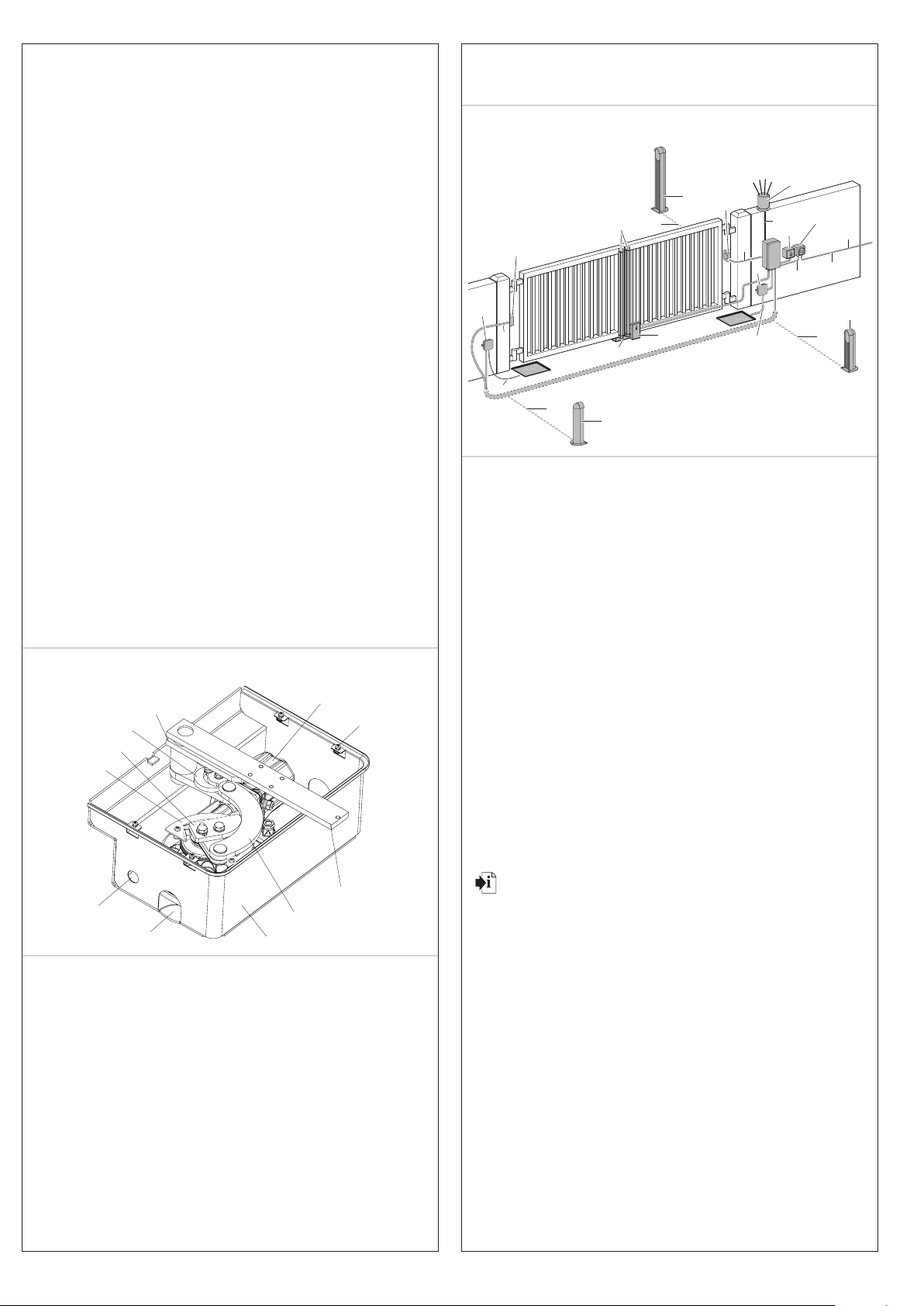
3. Gate system
3 / 1
11
b
3
c
6
5
c
c
9
1
a
4
2
10
a
a
11
2
a
8
b
a
1
7
This is just an example of a gate system and can vary depending on
the type of gate and the associated equipment. The gate system shown
comprises the following components:
1 Photocell
2 Photocell
3 Signal light
4 Key switch post (for code button, transponder, ...)
5 Wrench
6 Main switch (mains isolator switch)
7 Electric lock
8 Ground stop
9 Mains cable
10 Closing edge safety device (CESD)
11 Junction box with terminal strip
Cable cross-sections:
a 2 x 0.5 mm
b 6 x 0.75 mm
c 3 x 1.5 mm
d 2 x 0.75 mm
2
2
2
2
8
7
4
5
For the installation and cabling of the gate sensors, control elements
and safety equipment, the relevant installation instructions must be
observed.
Comfort 585 / 586 (assembled, without housing cover)
1 Crankset
2 Electric motor
3 Coverxingscrews
4 Wing device
5 Connecting rod
6 Operator housing
7 Water drain hole
8 Cable opening
9 Support plate for reference point sensor
10 Adjustable limit stop in CLOSING direction
11 Adjustable limit stop in OPEN direction
4 Operating instructions, Comfort 585, 586 (#102836 – GB)
4. Installation
DANGER!
NOTICE
4.1 Preparing for installation
Before commencing installation, the following works must be carried
out without fail.
Life-threatening danger due to electric shock!
• It is vital that you disconnect the operator system from the
power supply before commencing cabling work. Take measures
to ensure that the power supply remains disconnected for the
duration of the cabling work.
• Observe the local safety regulations.
• It is imperative that you lay power cables separately from control
cables.
The control voltage is 24V DC.
Material damage resulting from incorrect installation of the
operator!
To avoid installation errors and damage to the gate and operator
system, the following installation instructions must be observed at all
costs.
• Ensure that the gate is in good mechanical order:
– The gate can be moved easily.
– The gate opens and closes properly.
• Onlyusexingmaterialsthataresuitableforthefoundation
material in question.
Foundations
• Check the proposed position of the foundation.
Scope of supply
• Check that all the parts are present.
• Check that all the necessary accessory parts for your installation
situation are present.
Gate system
• Ensurethatyourgatesystemstructureissufcientlystabletoallow
for automation.
• Ensure that the gate can be easily moved by hand.
• Ensure that there are no obstructions in the path of movement of
the gate.
• Disassemble the gate latches or render them inoperable.
• Makesurethatthesizeofthetopgatehingeissufcientlylargefor
automatic gate operation.
• Remove all other hinges.
• Ensure that a suitable mains connection and a mains isolator
switch are available for your gate system.
Theminimumcross-sectionoftheearthcablemustbe3x1.5mm2.
• Ensure that all cables are suitable for outdoor use with respect to
UV resistance and cold resistance.
• Ensure that a suitable control unit is available for your gate system.
• In double wing gate systems, ensure that a cable connection is
available from the second motor unit to the control.
The minimum cross-section of this cable must be 6 x 0.75 mm2.
• Observe the following gate requirements:
➔ “11.1 Technical data”
The use of a mechanical ground stop in the CLOSED gate position is
recommended if the gate wing measures 1.8 metres or more.
For gate wing widths of 2 metres or more, the use of an electric lock is
recommended.
REFERENCE
When using and installing accessory equipment, observe the
corresponding documentation.
Operating instructions, Comfort 585, 586 (#102836 – GB) 5
 Loading...