

Page 1
OPERATING INSTRUCTIONS
1433.01XX
MOBILE OPERATING TABLE
YUNO OTN
GA 1433.01 EN 08
Page 2

Copyright notice
All rights reserved.
Any duplication, adaption or translation without prior written consent is prohibited unless otherwise
provided for in the relevant copyright laws.
© Copyright MAQUET GmbH
Subject to technical modification!
Illustrations and technical specifications may vary slightly from those in these Operating Instructions
as a result of ongoing product development.
V08.05 22-11-2013
1433.01XX
GA 1433.01 EN 08
Page 3

Table of contents
1 Introduction
1.1 Foreword . . . . . . . . . . . . . . . . . . . . . . . . . . . . . . . . . . . . . . . . . . . . . . . . . . . . . . . . . . . . . . . . . . . . . 1
1.2 How to use these operating instructions. . . . . . . . . . . . . . . . . . . . . . . . . . . . . . . . . . . . . . . . . . . . . . 1
1.2.1 General. . . . . . . . . . . . . . . . . . . . . . . . . . . . . . . . . . . . . . . . . . . . . . . . . . . . . . . . . . . . . . . . . . . . . . . 1
1.2.2 Abbreviations . . . . . . . . . . . . . . . . . . . . . . . . . . . . . . . . . . . . . . . . . . . . . . . . . . . . . . . . . . . . . . . . . . 1
1.2.3 Symbols . . . . . . . . . . . . . . . . . . . . . . . . . . . . . . . . . . . . . . . . . . . . . . . . . . . . . . . . . . . . . . . . . . . . . . 2
1.2.3.1 Order number . . . . . . . . . . . . . . . . . . . . . . . . . . . . . . . . . . . . . . . . . . . . . . . . . . . . . . . . . . . . . . . . . . 2
1.2.3.2 Cross-references . . . . . . . . . . . . . . . . . . . . . . . . . . . . . . . . . . . . . . . . . . . . . . . . . . . . . . . . . . . . . . . 2
1.2.3.3 Actions and responses . . . . . . . . . . . . . . . . . . . . . . . . . . . . . . . . . . . . . . . . . . . . . . . . . . . . . . . . . . . 2
1.2.3.4 Buttons and menus . . . . . . . . . . . . . . . . . . . . . . . . . . . . . . . . . . . . . . . . . . . . . . . . . . . . . . . . . . . . . 2
1.2.4 Definitions. . . . . . . . . . . . . . . . . . . . . . . . . . . . . . . . . . . . . . . . . . . . . . . . . . . . . . . . . . . . . . . . . . . . . 3
1.2.4.1 Design of safety notes . . . . . . . . . . . . . . . . . . . . . . . . . . . . . . . . . . . . . . . . . . . . . . . . . . . . . . . . . . . 3
1.2.4.2 Design for other notes . . . . . . . . . . . . . . . . . . . . . . . . . . . . . . . . . . . . . . . . . . . . . . . . . . . . . . . . . . . 3
1.2.4.3 Definition for 3-dimensional coordinate system . . . . . . . . . . . . . . . . . . . . . . . . . . . . . . . . . . . . . . . . 4
1.2.4.4 Definition of slope and tilt . . . . . . . . . . . . . . . . . . . . . . . . . . . . . . . . . . . . . . . . . . . . . . . . . . . . . . . . . 4
1.2.4.5 Definition of permissible overall load . . . . . . . . . . . . . . . . . . . . . . . . . . . . . . . . . . . . . . . . . . . . . . . . 5
1.2.4.6 Definition of protrusion . . . . . . . . . . . . . . . . . . . . . . . . . . . . . . . . . . . . . . . . . . . . . . . . . . . . . . . . . . . 5
1.2.4.7 Definition of area prone to explosion, Zone AP-M . . . . . . . . . . . . . . . . . . . . . . . . . . . . . . . . . . . . . . 5
1.2.4.8 Definition Positioning- / Transporting . . . . . . . . . . . . . . . . . . . . . . . . . . . . . . . . . . . . . . . . . . . . . . . . 5
1.2.4.9 Definition of travelling forwards / backwards . . . . . . . . . . . . . . . . . . . . . . . . . . . . . . . . . . . . . . . . . . 6
1.2.4.10 Definition of patient orientation . . . . . . . . . . . . . . . . . . . . . . . . . . . . . . . . . . . . . . . . . . . . . . . . . . . . . 7
1.2.5 Symbols used . . . . . . . . . . . . . . . . . . . . . . . . . . . . . . . . . . . . . . . . . . . . . . . . . . . . . . . . . . . . . . . . . . 8
1.3 Disposal . . . . . . . . . . . . . . . . . . . . . . . . . . . . . . . . . . . . . . . . . . . . . . . . . . . . . . . . . . . . . . . . . . . . . 10
1.3.1 General. . . . . . . . . . . . . . . . . . . . . . . . . . . . . . . . . . . . . . . . . . . . . . . . . . . . . . . . . . . . . . . . . . . . . . 10
1.3.2 Packing. . . . . . . . . . . . . . . . . . . . . . . . . . . . . . . . . . . . . . . . . . . . . . . . . . . . . . . . . . . . . . . . . . . . . . 10
1.3.3 Padding . . . . . . . . . . . . . . . . . . . . . . . . . . . . . . . . . . . . . . . . . . . . . . . . . . . . . . . . . . . . . . . . . . . . . 10
1.3.4 Rechargeable batteries/ Batteries . . . . . . . . . . . . . . . . . . . . . . . . . . . . . . . . . . . . . . . . . . . . . . . . . 10
1.3.5 MAQUET products . . . . . . . . . . . . . . . . . . . . . . . . . . . . . . . . . . . . . . . . . . . . . . . . . . . . . . . . . . . . . 10
1.3.6 Used electrical equipment . . . . . . . . . . . . . . . . . . . . . . . . . . . . . . . . . . . . . . . . . . . . . . . . . . . . . . . 10
1.3.6.1 Within the European Economic Community . . . . . . . . . . . . . . . . . . . . . . . . . . . . . . . . . . . . . . . . . . 10
1.3.6.2 Outside the European Economic Community. . . . . . . . . . . . . . . . . . . . . . . . . . . . . . . . . . . . . . . . . 10
1.4 Overview. . . . . . . . . . . . . . . . . . . . . . . . . . . . . . . . . . . . . . . . . . . . . . . . . . . . . . . . . . . . . . . . . . . . . 11
1.5 Basic requirements. . . . . . . . . . . . . . . . . . . . . . . . . . . . . . . . . . . . . . . . . . . . . . . . . . . . . . . . . . . . . 12
1.5.1 Use in accordance with the intended purpose . . . . . . . . . . . . . . . . . . . . . . . . . . . . . . . . . . . . . . . . 12
1.5.2 Applicable standards . . . . . . . . . . . . . . . . . . . . . . . . . . . . . . . . . . . . . . . . . . . . . . . . . . . . . . . . . . . 12
1.5.3 Intended purposes . . . . . . . . . . . . . . . . . . . . . . . . . . . . . . . . . . . . . . . . . . . . . . . . . . . . . . . . . . . . . 13
1.5.3.1 Mobile operating table YUNO . . . . . . . . . . . . . . . . . . . . . . . . . . . . . . . . . . . . . . . . . . . . . . . . . . . . . 13
1.5.3.2 Variants . . . . . . . . . . . . . . . . . . . . . . . . . . . . . . . . . . . . . . . . . . . . . . . . . . . . . . . . . . . . . . . . . . . . . 13
1.5.3.3 Product features . . . . . . . . . . . . . . . . . . . . . . . . . . . . . . . . . . . . . . . . . . . . . . . . . . . . . . . . . . . . . . . 13
1.5.3.4 Hand controls . . . . . . . . . . . . . . . . . . . . . . . . . . . . . . . . . . . . . . . . . . . . . . . . . . . . . . . . . . . . . . . . . 14
1.5.3.5 Side rails. . . . . . . . . . . . . . . . . . . . . . . . . . . . . . . . . . . . . . . . . . . . . . . . . . . . . . . . . . . . . . . . . . . . . 14
2 Basic safety instructions
2.1 Personal safety notes . . . . . . . . . . . . . . . . . . . . . . . . . . . . . . . . . . . . . . . . . . . . . . . . . . . . . . . . . . . 15
2.2 Safety notes for the OR table . . . . . . . . . . . . . . . . . . . . . . . . . . . . . . . . . . . . . . . . . . . . . . . . . . . . . 19
2.3 Safety notes regarding the use of accessories. . . . . . . . . . . . . . . . . . . . . . . . . . . . . . . . . . . . . . . . 20
2.4 Safety notes regarding padding . . . . . . . . . . . . . . . . . . . . . . . . . . . . . . . . . . . . . . . . . . . . . . . . . . . 22
1433.01XX
GA 1433.01 EN 08
I
Page 4

Table of contents
3 Operation and use
3.1 General . . . . . . . . . . . . . . . . . . . . . . . . . . . . . . . . . . . . . . . . . . . . . . . . . . . . . . . . . . . . . . . . . . . . . . 23
3.2 Acoustic signals issued by the OR table . . . . . . . . . . . . . . . . . . . . . . . . . . . . . . . . . . . . . . . . . . . . . 23
3.3 Set up the equipotential bonding . . . . . . . . . . . . . . . . . . . . . . . . . . . . . . . . . . . . . . . . . . . . . . . . . . . 24
3.4 Mains operation / battery operation . . . . . . . . . . . . . . . . . . . . . . . . . . . . . . . . . . . . . . . . . . . . . . . . . 25
3.4.1 Charge batteries (mains operation) . . . . . . . . . . . . . . . . . . . . . . . . . . . . . . . . . . . . . . . . . . . . . . . . . 25
3.4.2 Battery operation . . . . . . . . . . . . . . . . . . . . . . . . . . . . . . . . . . . . . . . . . . . . . . . . . . . . . . . . . . . . . . . 26
3.5 Connecting the service mounting point . . . . . . . . . . . . . . . . . . . . . . . . . . . . . . . . . . . . . . . . . . . . . . 27
3.6 Attaching the hand control to the side rail . . . . . . . . . . . . . . . . . . . . . . . . . . . . . . . . . . . . . . . . . . . . 28
3.7 Mechanical adjustments . . . . . . . . . . . . . . . . . . . . . . . . . . . . . . . . . . . . . . . . . . . . . . . . . . . . . . . . . 29
3.7.1 Accessory recognition . . . . . . . . . . . . . . . . . . . . . . . . . . . . . . . . . . . . . . . . . . . . . . . . . . . . . . . . . . . 29
3.7.2 Mounting and removing table width extensions (1001.75A0/76A0). . . . . . . . . . . . . . . . . . . . . . . . . 32
3.7.3 Mounting/removing the head rest . . . . . . . . . . . . . . . . . . . . . . . . . . . . . . . . . . . . . . . . . . . . . . . . . . 33
3.7.3.1 Mounting and removing the head rest using the head rest adapter (1130.81A0) . . . . . . . . . . . . . . 33
3.7.4 Mounting and removing the extension plate (1131.31XX). . . . . . . . . . . . . . . . . . . . . . . . . . . . . . . . 35
3.7.5 Seat plate extension . . . . . . . . . . . . . . . . . . . . . . . . . . . . . . . . . . . . . . . . . . . . . . . . . . . . . . . . . . . . 36
3.7.5.1 Mounting and removing the seat plate extension (1131.55XX) . . . . . . . . . . . . . . . . . . . . . . . . . . . . 36
3.7.6 Leg plates . . . . . . . . . . . . . . . . . . . . . . . . . . . . . . . . . . . . . . . . . . . . . . . . . . . . . . . . . . . . . . . . . . . . 37
3.7.6.1 Mounting and removing the pair of leg plates (1133.53BC). . . . . . . . . . . . . . . . . . . . . . . . . . . . . . . 37
3.7.6.2 Mounting and removing the leg plate (1133.58BC) . . . . . . . . . . . . . . . . . . . . . . . . . . . . . . . . . . . . 38
3.7.7 Basic table top . . . . . . . . . . . . . . . . . . . . . . . . . . . . . . . . . . . . . . . . . . . . . . . . . . . . . . . . . . . . . . . . . 39
3.7.7.1 Mounting/removing the standard plate. . . . . . . . . . . . . . . . . . . . . . . . . . . . . . . . . . . . . . . . . . . . . . . 39
3.7.7.2 Mounting / removing the extension plate (1433.66XC) . . . . . . . . . . . . . . . . . . . . . . . . . . . . . . . . . . 40
3.7.8 Mounting and removing the filler pieces for the pair of leg plates (1433.50AC) . . . . . . . . . . . . . . . 41
3.8 Padding . . . . . . . . . . . . . . . . . . . . . . . . . . . . . . . . . . . . . . . . . . . . . . . . . . . . . . . . . . . . . . . . . . . . . . 42
1433.01XX
II
GA 1433.01 EN 08
Page 5

Table of contents
4 Hand controls
4.1 General. . . . . . . . . . . . . . . . . . . . . . . . . . . . . . . . . . . . . . . . . . . . . . . . . . . . . . . . . . . . . . . . . . . . . . 43
4.2 Override control panel . . . . . . . . . . . . . . . . . . . . . . . . . . . . . . . . . . . . . . . . . . . . . . . . . . . . . . . . . . 44
4.2.1 Overview of override control panel . . . . . . . . . . . . . . . . . . . . . . . . . . . . . . . . . . . . . . . . . . . . . . . . . 45
4.2.2 Overview of displays. . . . . . . . . . . . . . . . . . . . . . . . . . . . . . . . . . . . . . . . . . . . . . . . . . . . . . . . . . . . 46
4.2.2.1 Overview of status display mains operation . . . . . . . . . . . . . . . . . . . . . . . . . . . . . . . . . . . . . . . . . . 46
4.2.2.2 Overview of the status display for battery operation. . . . . . . . . . . . . . . . . . . . . . . . . . . . . . . . . . . . 46
4.2.2.3 Overview of change display LOCK / UNLOCK . . . . . . . . . . . . . . . . . . . . . . . . . . . . . . . . . . . . . . . . 47
4.3 Corded hand controls . . . . . . . . . . . . . . . . . . . . . . . . . . . . . . . . . . . . . . . . . . . . . . . . . . . . . . . . . . . 48
4.3.1 Foot switch (1009.81G0/G1/G2). . . . . . . . . . . . . . . . . . . . . . . . . . . . . . . . . . . . . . . . . . . . . . . . . . . 48
4.3.2 Corded hand control (1433.90A0) . . . . . . . . . . . . . . . . . . . . . . . . . . . . . . . . . . . . . . . . . . . . . . . . . 48
4.3.3 Connecting corded hand controls . . . . . . . . . . . . . . . . . . . . . . . . . . . . . . . . . . . . . . . . . . . . . . . . . . 49
4.4 IR remote control (1433.91A0) . . . . . . . . . . . . . . . . . . . . . . . . . . . . . . . . . . . . . . . . . . . . . . . . . . . . 50
4.4.1 Control buttons and functions . . . . . . . . . . . . . . . . . . . . . . . . . . . . . . . . . . . . . . . . . . . . . . . . . . . . . 50
4.4.1.1 Switching on the illumination . . . . . . . . . . . . . . . . . . . . . . . . . . . . . . . . . . . . . . . . . . . . . . . . . . . . . 51
4.4.1.2 [Leg side] selector key . . . . . . . . . . . . . . . . . . . . . . . . . . . . . . . . . . . . . . . . . . . . . . . . . . . . . . . . . . 52
4.4.2 Special features of the IR remote control (1433.91A0) . . . . . . . . . . . . . . . . . . . . . . . . . . . . . . . . . 53
4.4.2.1 General. . . . . . . . . . . . . . . . . . . . . . . . . . . . . . . . . . . . . . . . . . . . . . . . . . . . . . . . . . . . . . . . . . . . . . 53
4.4.2.2 Acoustic signals . . . . . . . . . . . . . . . . . . . . . . . . . . . . . . . . . . . . . . . . . . . . . . . . . . . . . . . . . . . . . . . 53
4.4.2.3 IR code . . . . . . . . . . . . . . . . . . . . . . . . . . . . . . . . . . . . . . . . . . . . . . . . . . . . . . . . . . . . . . . . . . . . . . 53
4.4.2.4 Transmission power . . . . . . . . . . . . . . . . . . . . . . . . . . . . . . . . . . . . . . . . . . . . . . . . . . . . . . . . . . . . 53
4.4.2.5 Charging unit (1009.70A0) / Charging station (1009.71A0) . . . . . . . . . . . . . . . . . . . . . . . . . . . . . . 54
4.4.2.6 Mobile charger (1009.70A0) . . . . . . . . . . . . . . . . . . . . . . . . . . . . . . . . . . . . . . . . . . . . . . . . . . . . . . 54
4.4.2.7 Stationary charging station . . . . . . . . . . . . . . . . . . . . . . . . . . . . . . . . . . . . . . . . . . . . . . . . . . . . . . . 55
4.4.2.8 Inserting the IR remote control . . . . . . . . . . . . . . . . . . . . . . . . . . . . . . . . . . . . . . . . . . . . . . . . . . . . 56
4.4.2.9 Removing the IR remote control . . . . . . . . . . . . . . . . . . . . . . . . . . . . . . . . . . . . . . . . . . . . . . . . . . . 56
4.5 Display . . . . . . . . . . . . . . . . . . . . . . . . . . . . . . . . . . . . . . . . . . . . . . . . . . . . . . . . . . . . . . . . . . . . . . 57
4.5.1 General. . . . . . . . . . . . . . . . . . . . . . . . . . . . . . . . . . . . . . . . . . . . . . . . . . . . . . . . . . . . . . . . . . . . . . 57
4.5.2 Display design . . . . . . . . . . . . . . . . . . . . . . . . . . . . . . . . . . . . . . . . . . . . . . . . . . . . . . . . . . . . . . . . 57
4.5.3 Symbols for status bar . . . . . . . . . . . . . . . . . . . . . . . . . . . . . . . . . . . . . . . . . . . . . . . . . . . . . . . . . . 58
4.5.4 Symbols for the navigation bar . . . . . . . . . . . . . . . . . . . . . . . . . . . . . . . . . . . . . . . . . . . . . . . . . . . . 59
4.5.5 Standard patient positions . . . . . . . . . . . . . . . . . . . . . . . . . . . . . . . . . . . . . . . . . . . . . . . . . . . . . . . 60
4.5.5.1 FLEX / REFLEX position . . . . . . . . . . . . . . . . . . . . . . . . . . . . . . . . . . . . . . . . . . . . . . . . . . . . . . . . 60
4.5.5.2 BEACH CHAIR / BACK HORIZONTAL position . . . . . . . . . . . . . . . . . . . . . . . . . . . . . . . . . . . . . . 61
4.5.5.3 NORMAL/REVERSE patient orientation . . . . . . . . . . . . . . . . . . . . . . . . . . . . . . . . . . . . . . . . . . . . 62
4.5.6 Menu item [System information] . . . . . . . . . . . . . . . . . . . . . . . . . . . . . . . . . . . . . . . . . . . . . . . . . . . 62
4.5.7 [Patient positions] menu . . . . . . . . . . . . . . . . . . . . . . . . . . . . . . . . . . . . . . . . . . . . . . . . . . . . . . . . . 63
4.5.7.1 Select the patient position function . . . . . . . . . . . . . . . . . . . . . . . . . . . . . . . . . . . . . . . . . . . . . . . . . 63
4.5.7.2 Moving into patient position . . . . . . . . . . . . . . . . . . . . . . . . . . . . . . . . . . . . . . . . . . . . . . . . . . . . . . 64
4.5.7.3 Saving the patient position . . . . . . . . . . . . . . . . . . . . . . . . . . . . . . . . . . . . . . . . . . . . . . . . . . . . . . . 64
4.5.7.4 Editing names. . . . . . . . . . . . . . . . . . . . . . . . . . . . . . . . . . . . . . . . . . . . . . . . . . . . . . . . . . . . . . . . . 65
4.5.8 [Settings] menu. . . . . . . . . . . . . . . . . . . . . . . . . . . . . . . . . . . . . . . . . . . . . . . . . . . . . . . . . . . . . . . . 66
4.5.8.1 Selecting the [Settings] menu . . . . . . . . . . . . . . . . . . . . . . . . . . . . . . . . . . . . . . . . . . . . . . . . . . . . . 66
4.5.8.2 Activating and deactivating the operating table lock. . . . . . . . . . . . . . . . . . . . . . . . . . . . . . . . . . . . 66
4.5.8.3 Activating and deactivating the table top lock. . . . . . . . . . . . . . . . . . . . . . . . . . . . . . . . . . . . . . . . . 67
4.5.8.4 Switching illumination ON / OFF. . . . . . . . . . . . . . . . . . . . . . . . . . . . . . . . . . . . . . . . . . . . . . . . . . . 68
4.5.8.5 Switching the signal tone at the column ON / OFF. . . . . . . . . . . . . . . . . . . . . . . . . . . . . . . . . . . . . 68
4.5.9 [Fast memory] menu. . . . . . . . . . . . . . . . . . . . . . . . . . . . . . . . . . . . . . . . . . . . . . . . . . . . . . . . . . . . 69
4.5.9.1 Selecting the function . . . . . . . . . . . . . . . . . . . . . . . . . . . . . . . . . . . . . . . . . . . . . . . . .
4.5.9.2 Move into patient position . . . . . . . . . . . . . . . . . . . . . . . . . . . . . . . . . . . . . . . . . . . . . . . . . . . . . . . . 69
4.5.9.3 Saving patient position . . . . . . . . . . . . . . . . . . . . . . . . . . . . . . . . . . . . . . . . . . . . . . . . . . . . . . . . . . 70
4.6 Adjustment functions . . . . . . . . . . . . . . . . . . . . . . . . . . . . . . . . . . . . . . . . . . . . . . . . . . . . . . . . . . . 71
4.6.1 Moving/immobilising the OR table . . . . . . . . . . . . . . . . . . . . . . . . . . . . . . . . . . . . . . . . . . . . . . . . . 71
4.6.1.1 Moving the OR table using(UNLOCK) . . . . . . . . . . . . . . . . . . . . . . . . . . . . . . . . . . . . . . . . . . . . . . 72
4.6.1.2 Standing the OR table on the floor (LOCK) . . . . . . . . . . . . . . . . . . . . . . . . . . . . . . . . . . . . . . . . . . 73
4.6.2 Lowering / raising the patient (table top) . . . . . . . . . . . . . . . . . . . . . . . . . . . . . . . . . . . . . . . . . . . . 73
. . . . . . . . . . 69
1433.01XX
GA 1433.01 EN 08
III
Page 6

Table of contents
4.6.3 Motorised adjustment of the table top . . . . . . . . . . . . . . . . . . . . . . . . . . . . . . . . . . . . . . . . . . . . . . . 74
4.6.4 Aligning the patient horizontally . . . . . . . . . . . . . . . . . . . . . . . . . . . . . . . . . . . . . . . . . . . . . . . . . . . . 75
4.6.5 Inclining the patient . . . . . . . . . . . . . . . . . . . . . . . . . . . . . . . . . . . . . . . . . . . . . . . . . . . . . . . . . . . . . 76
4.6.6 Tilting the patient . . . . . . . . . . . . . . . . . . . . . . . . . . . . . . . . . . . . . . . . . . . . . . . . . . . . . . . . . . . . . . . 77
4.6.7 Deactivating the lock function temporarily . . . . . . . . . . . . . . . . . . . . . . . . . . . . . . . . . . . . . . . . . . . . 78
4.6.8 Aligning the leg plate horizontally . . . . . . . . . . . . . . . . . . . . . . . . . . . . . . . . . . . . . . . . . . . . . . . . . . 78
4.7 Explanation of instructions for use . . . . . . . . . . . . . . . . . . . . . . . . . . . . . . . . . . . . . . . . . . . . . . . . . . 79
4.7.1 Height for operating table lock . . . . . . . . . . . . . . . . . . . . . . . . . . . . . . . . . . . . . . . . . . . . . . . . . . . . . 79
4.7.2 Risk of collision with traction bars . . . . . . . . . . . . . . . . . . . . . . . . . . . . . . . . . . . . . . . . . . . . . . . . . . 79
5 Display notes
5.1 General . . . . . . . . . . . . . . . . . . . . . . . . . . . . . . . . . . . . . . . . . . . . . . . . . . . . . . . . . . . . . . . . . . . . . . 80
5.1.1 Structure of display notes . . . . . . . . . . . . . . . . . . . . . . . . . . . . . . . . . . . . . . . . . . . . . . . . . . . . . . . . 80
5.2 Notes on operation / special notes on operation . . . . . . . . . . . . . . . . . . . . . . . . . . . . . . . . . . . . . . .80
5.3 Warning notes / Status messages . . . . . . . . . . . . . . . . . . . . . . . . . . . . . . . . . . . . . . . . . . . . . . . . . . 82
6 Extension positioning
6.1 Assembling the extension device. . . . . . . . . . . . . . . . . . . . . . . . . . . . . . . . . . . . . . . . . . . . . . . . . . . 85
6.1.1 Mounting the extension plate (1433.66XC) . . . . . . . . . . . . . . . . . . . . . . . . . . . . . . . . . . . . . . . . . . . 85
6.1.2 Mounting the traction bars . . . . . . . . . . . . . . . . . . . . . . . . . . . . . . . . . . . . . . . . . . . . . . . . . . . . . . . . 85
6.1.3 Mounting the pair of leg plates (1433.50AC) . . . . . . . . . . . . . . . . . . . . . . . . . . . . . . . . . . . . . . . . . . 86
6.1.4 Mounting the height adjustment. . . . . . . . . . . . . . . . . . . . . . . . . . . . . . . . . . . . . . . . . . . . . . . . . . . . 86
6.1.5 Mounting the screw tension device . . . . . . . . . . . . . . . . . . . . . . . . . . . . . . . . . . . . . . . . . . . . . . . . . 87
6.1.6 Mounting the countertraction post . . . . . . . . . . . . . . . . . . . . . . . . . . . . . . . . . . . . . . . . . . . . . . . . . . 87
6.1.7 Fixing patient's leg in the extension shoe . . . . . . . . . . . . . . . . . . . . . . . . . . . . . . . . . . . . . . . . . . . . 88
6.1.8 Mounting the extension shoe (1003.67X0) . . . . . . . . . . . . . . . . . . . . . . . . . . . . . . . . . . . . . . . . . . . 88
6.1.9 Removing the pair of leg plates . . . . . . . . . . . . . . . . . . . . . . . . . . . . . . . . . . . . . . . . . . . . . . . . . . . . 89
6.2 Setting the extension device . . . . . . . . . . . . . . . . . . . . . . . . . . . . . . . . . . . . . . . . . . . . . . . . . . . . . . 89
6.2.1 General . . . . . . . . . . . . . . . . . . . . . . . . . . . . . . . . . . . . . . . . . . . . . . . . . . . . . . . . . . . . . . . . . . . . . . 89
6.2.2 Adjusting the height of the extension device . . . . . . . . . . . . . . . . . . . . . . . . . . . . . . . . . . . . . . . . . . 90
6.2.3 Abducting the extension device . . . . . . . . . . . . . . . . . . . . . . . . . . . . . . . . . . . . . . . . . . . . . . . . . . . . 91
6.3 Setting the screw tension device . . . . . . . . . . . . . . . . . . . . . . . . . . . . . . . . . . . . . . . . . . . . . . . . . . . 92
6.3.1 Setting the internal / external rotation of the extension shoe . . . . . . . . . . . . . . . . . . . . . . . . . . . . . . 93
6.4 Detaching the extension device . . . . . . . . . . . . . . . . . . . . . . . . . . . . . . . . . . . . . . . . . . . . . . . . . . . . 94
6.4.1 Releasing the traction of the screw tension device . . . . . . . . . . . . . . . . . . . . . . . . . . . . . . . . . . . . .94
6.4.2 Aligning the traction bars . . . . . . . . . . . . . . . . . . . . . . . . . . . . . . . . . . . . . . . . . . . . . . . . . . . . . . . . . 94
6.4.3 Mounting the pair of leg plates (1433.50AC) . . . . . . . . . . . . . . . . . . . . . . . . . . . . . . . . . . . . . . . . . . 95
6.4.4 Removing the extension shoe (1003.67X0). . . . . . . . . . . . . . . . . . . . . . . . . . . . . . . . . . . . . . . . . . .95
6.4.5 Removing the countertraction post . . . . . . . . . . . . . . . . . . . . . . . . . . . . . . . . . . . . . . . . . . . . . . . . . 96
6.4.6 Removing the screw tension device . . . . . . . . . . . . . . . . . . . . . . . . . . . . . . . . . . . . . . . . . . . . . . . . 96
6.4.7 Removing the gas strut assisted height adjustment . . . . . . . . . . . . . . . . . . . . . . . . . . . . . . . . . . . . 97
6.4.8 Removing the traction bars . . . . . . . . . . . . . . . . . . . . . . . . . . . . . . . . . . . . . . . . . . . . . . . . . . . . . . . 97
6.4.9 Removing the leg plates . . . . . . . . . . . . . . . . . . . . . . . . . . . . . . . . . . . . . . . . . . . . . . . . . . . . . . . . . 98
6.4.10 Removing the extension plate . . . . . . . . . . . . . . . . . . . . . . . . . . . . . . . . . . . . . . . . . . . . . . . . . . . . . 98
7 Patient positioning
7.1 Table top configuration for an overall load of up to 155 kg . . . . . . . . . . . . . . . . . . . . . . . . . . . . . . 100
7.1.1 NORMAL patient orientation . . . . . . . . . . . . . . . . . . . . . . . . . . . . . . . . . . . . . . . . . . . . . . . . . . . . . 101
7.1.2 REVERSE patient orientation . . . . . . . . . . . . . . . . . . . . . . . . . . . . . . . . . . . . . . . . . . . . . . . . . . . . 102
7.2 Table top configuration for an overall load of 155 kg to 250 kg . . . . . . . . . . . . . . . . . . . . . . . . . . . 103
7.2.1 NORMAL patient orientation . . . . . . . . . . . . . . . . . . . . . . . . . . . . . . . . . . . . . . . . . . . . . . . . . . . . . 104
7.2.2 REVERSE patient orientation . . . . . . . . . . . . . . . . . . . . . . . . . . . . . . . . . . . . . . . . . . . . . . . . . . . . 105
7.3 Table top configuration for an overall load of 250 kg to 454 kg . . . . . . . . . . . . . . . . . . . . . . . . . . . 106
7.4 Special accessories YUNO OTN . . . . . . . . . . . . . . . . . . . . . . . . . . . . . . . . . . . . . . . . . . . . . . . . . .108
1433.01XX
IV
GA 1433.01 EN 08
Page 7

Table of contents
8 Cleaning and disinfection
8.1 General. . . . . . . . . . . . . . . . . . . . . . . . . . . . . . . . . . . . . . . . . . . . . . . . . . . . . . . . . . . . . . . . . . . . . 109
8.2 Cleaning . . . . . . . . . . . . . . . . . . . . . . . . . . . . . . . . . . . . . . . . . . . . . . . . . . . . . . . . . . . . . . . . . . . . 111
8.2.1 General. . . . . . . . . . . . . . . . . . . . . . . . . . . . . . . . . . . . . . . . . . . . . . . . . . . . . . . . . . . . . . . . . . . . . 111
8.2.2 Cleaning procedure . . . . . . . . . . . . . . . . . . . . . . . . . . . . . . . . . . . . . . . . . . . . . . . . . . . . . . . . . . . 112
8.3 Disinfection . . . . . . . . . . . . . . . . . . . . . . . . . . . . . . . . . . . . . . . . . . . . . . . . . . . . . . . . . . . . . . . . . . 112
8.3.1 General. . . . . . . . . . . . . . . . . . . . . . . . . . . . . . . . . . . . . . . . . . . . . . . . . . . . . . . . . . . . . . . . . . . . . 112
8.3.2 Suitable disinfectants . . . . . . . . . . . . . . . . . . . . . . . . . . . . . . . . . . . . . . . . . . . . . . . . . . . . . . . . . . 113
8.3.3 Disinfection procedure . . . . . . . . . . . . . . . . . . . . . . . . . . . . . . . . . . . . . . . . . . . . . . . . . . . . . . . . . 114
8.4 Stainless steel surfaces . . . . . . . . . . . . . . . . . . . . . . . . . . . . . . . . . . . . . . . . . . . . . . . . . . . . . . . . 114
8.5 Padding . . . . . . . . . . . . . . . . . . . . . . . . . . . . . . . . . . . . . . . . . . . . . . . . . . . . . . . . . . . . . . . . . . . . 114
8.6 Cleaning and manual disinfection of the swivel castors . . . . . . . . . . . . . . . . . . . . . . . . . . . . . . . . 114
9 Maintenance
9.1 Visual and functional inspections . . . . . . . . . . . . . . . . . . . . . . . . . . . . . . . . . . . . . . . . . . . . . . . . . 115
9.2 Malfunctions and troubleshooting . . . . . . . . . . . . . . . . . . . . . . . . . . . . . . . . . . . . . . . . . . . . . . . . . 117
9.2.1 General. . . . . . . . . . . . . . . . . . . . . . . . . . . . . . . . . . . . . . . . . . . . . . . . . . . . . . . . . . . . . . . . . . . . . 117
9.2.2 Troubleshooting . . . . . . . . . . . . . . . . . . . . . . . . . . . . . . . . . . . . . . . . . . . . . . . . . . . . . . . . . . . . . . 117
9.3 Inspection and Maintenance. . . . . . . . . . . . . . . . . . . . . . . . . . . . . . . . . . . . . . . . . . . . . . . . . . . . . 118
9.4 Repair . . . . . . . . . . . . . . . . . . . . . . . . . . . . . . . . . . . . . . . . . . . . . . . . . . . . . . . . . . . . . . . . . . . . . . 118
10 Technical specifications
10.1 General specifications . . . . . . . . . . . . . . . . . . . . . . . . . . . . . . . . . . . . . . . . . . . . . . . . . . . . . . . . . 119
10.2 Ambient conditions . . . . . . . . . . . . . . . . . . . . . . . . . . . . . . . . . . . . . . . . . . . . . . . . . . . . . . . . . . . . 119
10.3 Electrical specifications . . . . . . . . . . . . . . . . . . . . . . . . . . . . . . . . . . . . . . . . . . . . . . . . . . . . . . . . 119
10.4 Weights. . . . . . . . . . . . . . . . . . . . . . . . . . . . . . . . . . . . . . . . . . . . . . . . . . . . . . . . . . . . . . . . . . . . . 120
10.5 Dimensions. . . . . . . . . . . . . . . . . . . . . . . . . . . . . . . . . . . . . . . . . . . . . . . . . . . . . . . . . . . . . . . . . . 120
10.6 Inclination . . . . . . . . . . . . . . . . . . . . . . . . . . . . . . . . . . . . . . . . . . . . . . . . . . . . . . . . . . . . . . . . . . . 121
10.7 Tilt. . . . . . . . . . . . . . . . . . . . . . . . . . . . . . . . . . . . . . . . . . . . . . . . . . . . . . . . . . . . . . . . . . . . . . . . . 121
10.8 Motorised joint . . . . . . . . . . . . . . . . . . . . . . . . . . . . . . . . . . . . . . . . . . . . . . . . . . . . . . . . . . . . . . . 122
10.8.1 REVERSE mounting point . . . . . . . . . . . . . . . . . . . . . . . . . . . . . . . . . . . . . . . . . . . . . . . . . . . . . . 122
10.8.2 NORMAL mounting point . . . . . . . . . . . . . . . . . . . . . . . . . . . . . . . . . . . . . . . . . . . . . . . . . . . . . . . 122
10.9 Radiolucent area . . . . . . . . . . . . . . . . . . . . . . . . . . . . . . . . . . . . . . . . . . . . . . . . . . . . . . . . . . . . . 123
10.10 Extension device . . . . . . . . . . . . . . . . . . . . . . . . . . . . . . . . . . . . . . . . . . . . . . . . . . . . . . . . . . . . . 124
11 Approved accessories
11.1 General. . . . . . . . . . . . . . . . . . . . . . . . . . . . . . . . . . . . . . . . . . . . . . . . . . . . . . . . . . . . . . . . . . . . . 125
11.2 Accessories for head-end mounting point . . . . . . . . . . . . . . . . . . . . . . . . . . . . . . . . . . . . . . . . . . 126
11.2.1 Maximum overall load of 155 kg . . . . . . . . . . . . . . . . . . . . . . . . . . . . . . . . . . . . . . . . . . . . . . . . . . 126
11.2.2 Maximum overall load of 250 kg . . . . . . . . . . . . . . . . . . . . . . . . . . . . . . . . . . . . . . . . . . . . . . . . . . 127
11.2.3 Maximum overall load of 454 kg . . . . . . . . . . . . . . . . . . . . . . . . . . . . . . . . . . . . . . . . . . . . . . . . . . 128
11.3 Accessories for NORMAL mounting point (back plate mounting point) . . . . . . . . . . . . . . . . . . . . 129
11.3.1 Maximum overall load of 155 kg . . . . . . . . . . . . . . . . . . . . . . . . . . . . . . . . . . . . . . . . . . . . . . . . . . 129
11.3.2 Maximum overall load of 250 kg . . . . . . . . . . . . . . . . . . . . . . . . . . . . . . . . . . . . . . . . . . . . . . . . . . 135
11.3.3 Maximum overall load of 454 kg . . . . . . . . . . . . . . . . . . . . . . . . . . . . . . . . . . . . . . . . . . . . . . . . . . 140
11.4 Accessories for REVERSE mounting plate (leg plate mounting point). . . . . . . . . . . . . . . . . . . . . 141
11.4.1 Maximum overall load of 155 kg . . . . . . . . . . . . . . . . . . . . . . . . . . . . . . . . . . . . . . . . . . . . . . . . . . 141
11.4.2 Maximum overall load of 250 kg . . . . . . . . . . . . . . . . . . . . . . . . . . . . . . . . . . . . . . . . . . . . . . . . . . 143
11.5 YUNO accessories . . . . . . . . . . . . . . . . . . . . . . . . . . . . . . . . . . . . . . . . . . . . . . . . . . . . . . . . . . . . 145
11.5.1 YUNO accessories, overall load 250 kg . . . . . . . . . . . . . . . . . . . . . . . . . . . . . . . . . . . . . . . . . . . . 145
11.5.2 Side rail accessories. . . . . . . . . . . . . . . . . . . . . . . . . . . . . . . . . . . . . . . . . . . . . . . . . . . . . . . . . . . 145
11.5.3 Hand controls . . . . . . . . . . . . . . . . . . . . . . . . . . . . . . . . . . . . . . . . . . . . . . . . . . . . . . . . . . . . . . . . 146
1433.01XX
GA 1433.01 EN 08
V
Page 8

Table of contents
1433.01XX
VI
GA 1433.01 EN 08
Page 9

1Introduction
1.1 Foreword
Introduction
Foreword
1
Your facility has selected the leading-edge
medical technology made by MAQUET.
We sincerely appreciate the trust you have
placed in us.
MAQUET is a member of the GETINGE group
which is consistently directing its attention to
pioneering medico-technical solutions.
1.2 How to use these operating instructions
1.2.1 General
These operating instructions are provided to
familiarise you with the features of this
MAQUET product. They are subdivided into
several chapters.
MAQUET is one of the world’s leading suppliers
for emergency rooms, operating rooms and
intensive care units. MAQUET has been
standing for innovation and advance in medical
technology ever since it was founded in 1838.
Solutions relevant to the needs of practice and
customer-oriented services optimise working
cycles and boost economy in hospitals – all to
the benefit of the patient.
Please note:
• Please read these operating instructions
carefully and completely before using the
product for the first time.
• Always proceed in accordance with the
information contained herein.
• Store these operating instructions in a
location near the product.
1.2.2 Abbreviations
EMC Electromagnetic compatibility
EN European standard
EU European Economic Community
IR Infrared
INT Intermittent
IPS Internal Power Source
LED Light Emitting Diode
OR table Operating table
PUR Polyurethane integral foam
SELV Safety Extra Low Voltage
SFC Soft Foam Core (special foam core)
1433.01XX
GA 1433.01 EN 08
1
Page 10

Introduction
1
How to use these operating instructions
1.2.3 Symbols
1.2.3.1 Order number
An "X" in the order number (e.g. 1122.33X4) is
a placeholder for a number of variants.
1.2.3.2 Cross-references
References to other pages in these operating
instructions are identified with a double arrow
symbol "
1.2.3.3 Actions and responses
The "
the user while the "
reaction that this will induce in the system.
".
" symbol identifies an action taken by
" symbol identifies the
Example:
Turn on the light switch.
Lamp lights up.
1.2.3.4 Buttons and menus
Buttons and menus are enclosed in square
brackets.
Example:
Press the [DOWN] button in the [Operation]
menu.
1433.01XX
2
GA 1433.01 EN 08
Page 11
1.2.4 Definitions
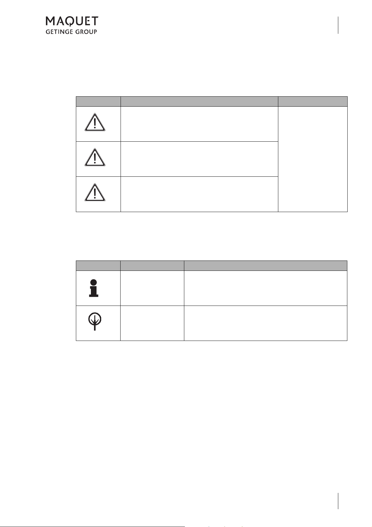
1.2.4.1 Design of safety notes
Pictogram Descriptor Text
D ANGER!
How to use these operating instructions
Indicates a direct and immediate risk
to persons, which may be fatal or
result in most serious injury.
Introduction
1
The text for the safety
note describes the type
of risk and how to avert
it.
W ARNING!
C AUTION!
Fig. 1: Design of safety notes
1.2.4.2 Design for other notes
Notes not referring to personal injury or
property damage are used as follows:
Pictogram Descriptor Reference to
N OTE
E NVIRONMENT
Indicates a potential risk to persons
or property which may result in health
hazard or grave property damage.
Indicates a potential risk to property
which may result in property damage.
Supplementary assistance or further useful information.
Proper disposal.
Fig. 2: Design for other notes
1433.01XX
GA 1433.01 EN 08
3
Page 12
Introduction
1
How to use these operating instructions
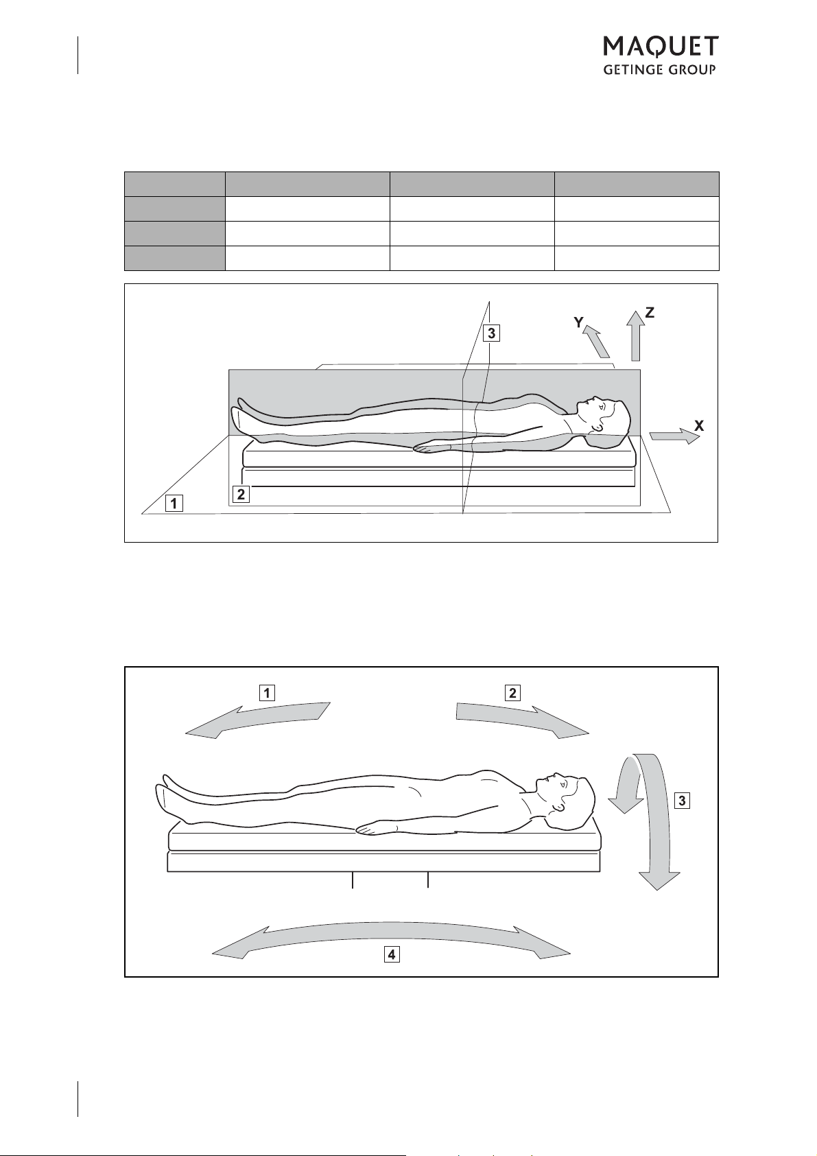
1.2.4.3 Definition for 3-dimensional coordinate system
Reference X axis Y axis Z axis
Product Longitudinal direction Lateral direction Height
Patient Longitudinal Transverse Sagittal
Neutral Horizontal Horizontal Vertical
Fig. 3: Definition of terms for the 3-dimensional coordinate system
1 Frontal plane (horizontal plane)
2 Sagittal plane
1.2.4.4 Definition of slope and tilt
3 Transverse plane
1433.01XX
4
GA 1433.01 EN 08
Fig. 4: Definition of slope and tilt
1 Reverse Trendelenburg (foot down)
2 Trendelenburg (head down)
3 Tilt
4 Slope
Page 13
1.2.4.5 Definition of permissible overall load
1
Introduction
How to use these operating instructions
1
The "permissible overall load" results from adding up patient weight, side rail accessory weight
and positioning aids. The "permissible overall
load" is the load which may be put on the table
top.
1.2.4.6 Definition of protrusion
Protrusion is the gap between the mounting
point(s) of a table top to the relevant outer edge
of the table top components (e.g. head rest, leg
plates) applied to the front.
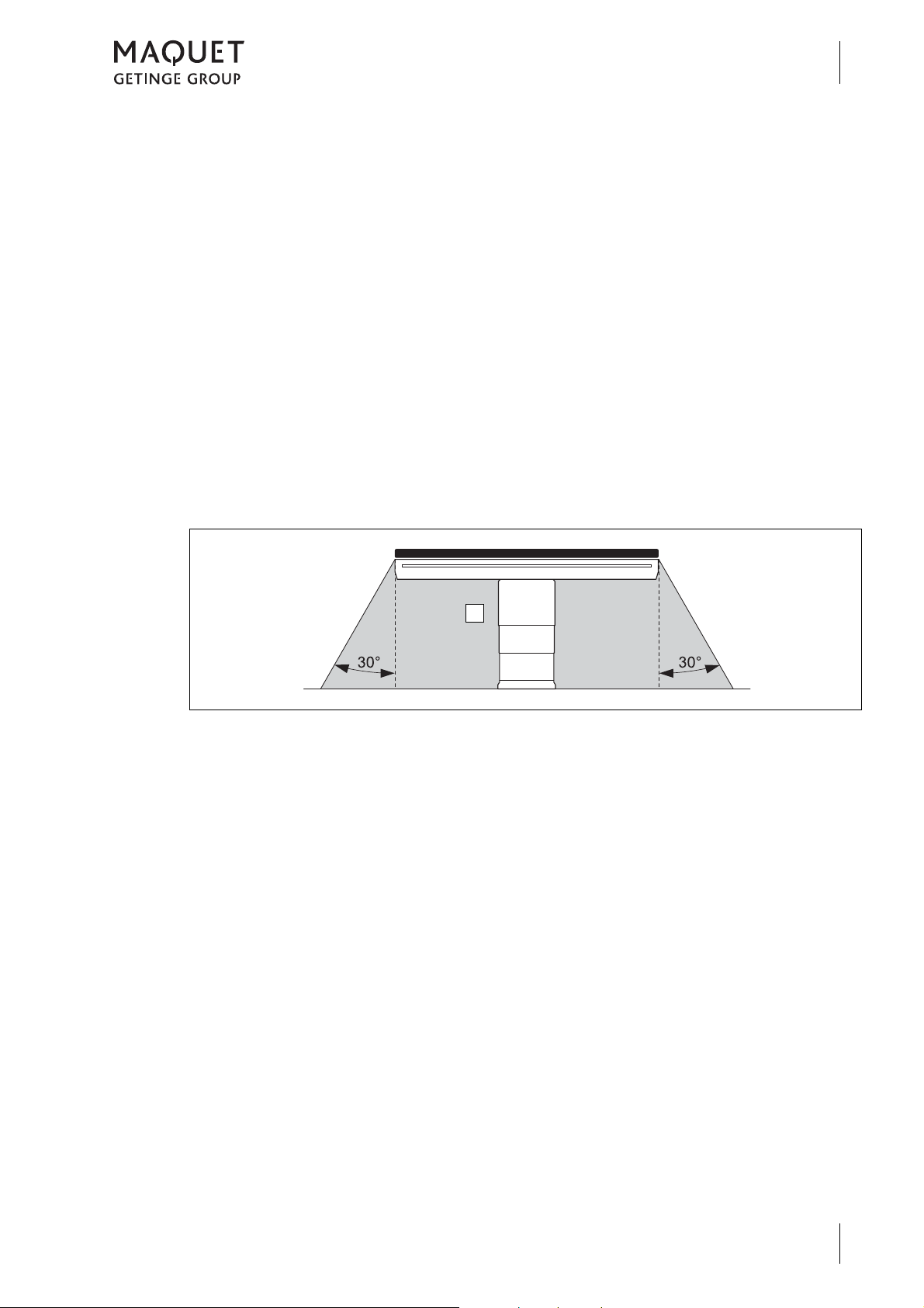
1.2.4.7 Definition of area prone to explosion, Zone AP-M
The medical environment is designated as
"Zone AP-M" (1).
Restrictions might result from the components
table top and transporter for which other overall
loads may be valid, or from special patient positions.
The maximum protrusion of a table top may not
be exceeded.
Fig. 5: Area prone to explosion, Zone AP-M
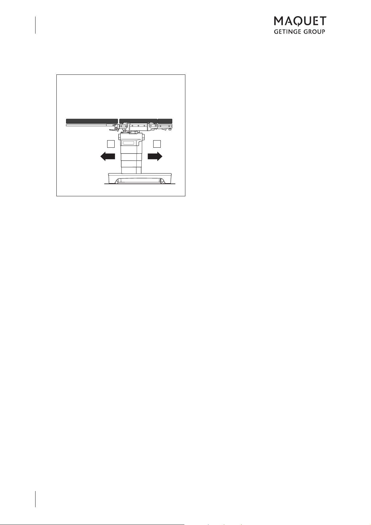
1.2.4.8 Definition Positioning- / Transporting
When moving, a distinction is made between
moving the mobile operating table with a patient
and without a patient.
Positioning
Positioning refers to the process of moving the
mobile operating table with a patient within the
operating room.
Transporting
Transporting refers to the process of moving
the mobile operating table without a patient in
the operating room.
1433.01XX
GA 1433.01 EN 08
5
Page 14
Introduction
12
1
How to use these operating instructions
1.2.4.9 Definition of travelling forwards / backwards
Fig. 6: Travelling forwards / backwards
The following definition applies to motor-powered motion:
• forwards (1)
• backwards (2)
1433.01XX
6
GA 1433.01 EN 08
Page 15
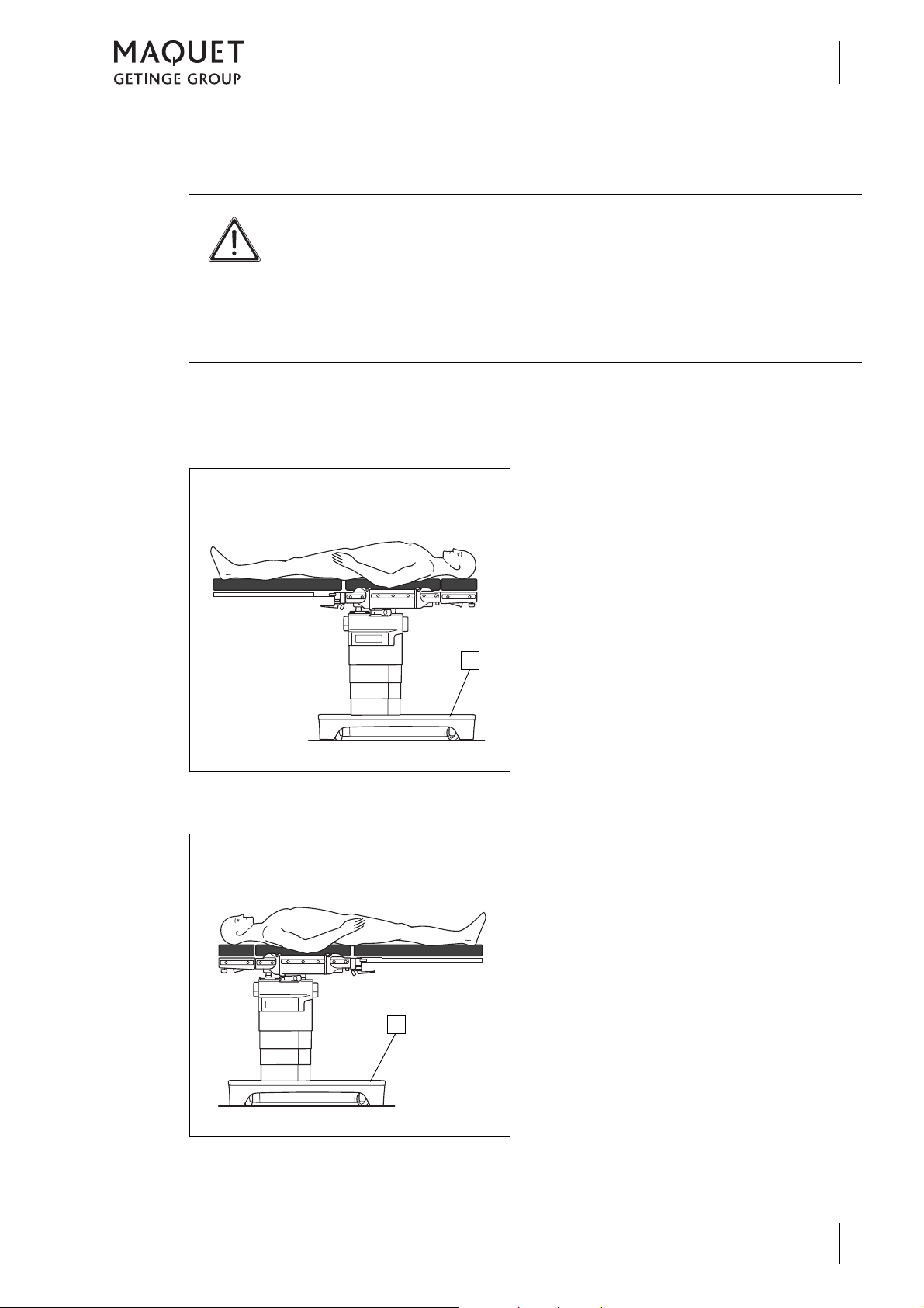
1.2.4.10 Definition of patient orientation
1
1
W ARNING!
Risk of injury!
Incorrectly adjusted patient orientation may cause adjustment of the
operating table in a direction that was not intended.
Check the correct patient orientation prior to making any adjustments.
The patient orientation is indicated in the status bar on the display on the hand
control.
The patient orientation depends on the position
of the patient on the table top with regard to the
operating table base (1).
NORMAL patient orientation
Introduction
How to use these operating instructions
The upper part of the patient's body is located
above the longer section of the operating table
base (1).
1
Fig. 7: NORMAL patient orientation
REVERSE patient orientation
Fig. 8: REVERSE patient orientation
The legs are located above the longer section
of the operating table base (1).
1433.01XX
GA 1433.01 EN 08
7
Page 16
Introduction
1
How to use these operating instructions
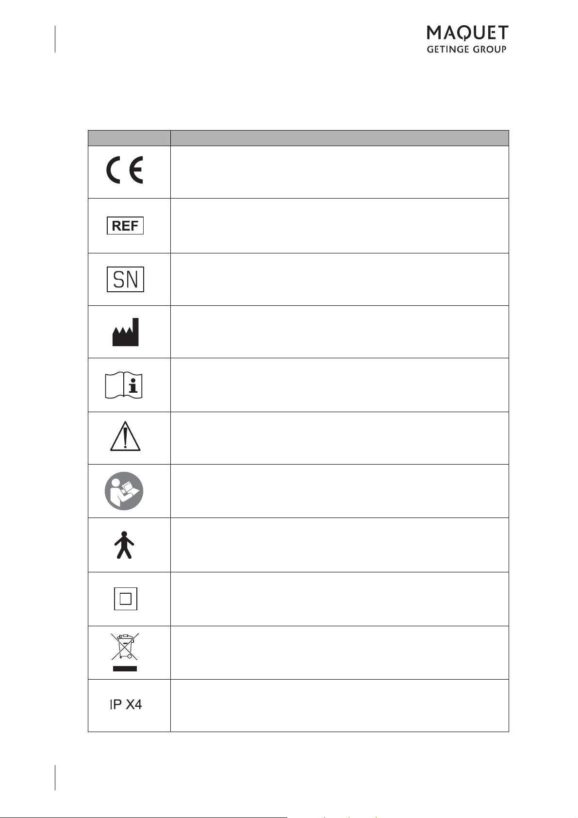
1.2.5 Symbols used
Symbols are attached to products, type plates and packaging.
Symbols Identification
Labelling for Class I products, developed and marketed in compliance with
Medical Device Directive 93/42/EU.
Labelling in compliance with the ISO 15223-1 standard.
Symbol for "Product number"
Labelling in compliance with the ISO 15223 -1 standard.
Symbol for "Serial number".
Designation in compliance with the ISO 15223-1 standard.
Symbol for "Name and address of the manufacturer as well as date of
manufacture".
Labelling in compliance with the IEC 60601-1 standard.
Symbol for "Follow Operating Instructions".
Labelling in compliance with the IEC 60601-1 standard.
Symbol for "Observe the accompanying documents".
Symbol for "Observe operating instructions".
Labelling for devices incorporating a Type B applied part as defined in the
IEC 60601-1 standard.
Degree of protection against electric shock.
Labelling in compliance with the IEC 60601-1 standard.
Symbol for "Class II".
Labelling as per 2002/96/EU Directive
(Directive on Waste Electrical and Electronic Equipment).
Symbol for "Do not dispose of at the municipal collection points for used
electrical equipment".
1433.01XX
8
GA 1433.01 EN 08
Labelling as per IEC 60529 standard.
Symbol for "splash protection".
Fig. 9: Symbols (Part 1 of 2)
Page 17
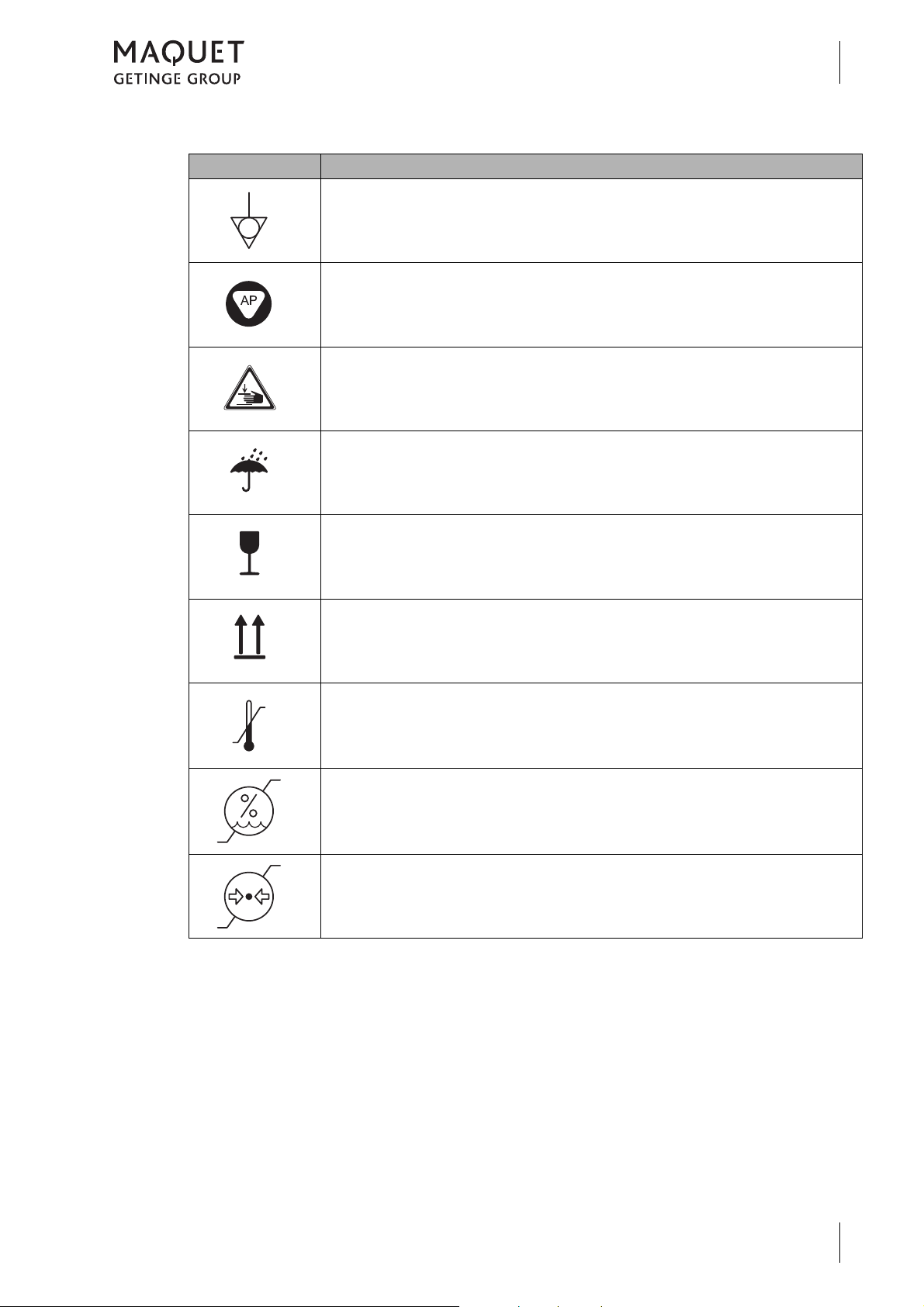
Symbols Identification
Labelling in compliance with the IEC 60601-1 standard.
Symbol for "Potential equalisation".
Labelling of Category AP equipment as per the IEC 60601-1 standard.
Explosion protection by avoiding sources of ignition when using flammable
blends of anaesthetics which are mixed with air, oxygen or nitrous oxide.
Labelling in compliance with the BGV A 8 Accident Prevention Regulations
(previously VBG 125).
Symbol for "Risk of pinching and crushing".
Packaging label.
Symbol for "Keep dry".
Introduction
How to use these operating instructions
1
Packaging label.
Symbol for "Fragile! Handle with care".
Packaging label.
Symbol for "Top".
Labelling in compliance with the ISO 15223 -1 standard.
Symbol for "Temperature range".
Labelling in compliance with the ISO 15223-1.
Symbol for "Relative humidity".
Labelling in compliance with the ISO 15223-1.
Symbol for "Air pressure".
Fig. 9: Symbols (Part 2 of 2)
1433.01XX
GA 1433.01 EN 08
9
Page 18

Introduction
1
Disposal
1.3 Disposal
1.3.1 General
Used products or parts thereof may be contaminated. To prevent potential infection, please
clean and disinfect the product prior to return/disposal.
1.3.2 Packing
The packing is made of materials compatible
with the environment. MAQUET will dispose of
the packing materials upon request.
1.3.3 Padding
Padding can be disposed of as normal household waste.
1.3.4 Rechargeable batteries/ Batteries
Rechargeable batteries/batteries can be turned
in to your local disposal system.
1.3.5 MAQUET products
MAQUET will take back used products or those
which are no longer in service.
1.3.6 Used electrical equipment
1.3.6.1 Within the European Economic Community
This product is governed by the 2002/96/EU Directive (Directive on Waste Electrical and Electronic Equipment).
This product has not been registered for use in
private households; disposal using municipal
1.3.6.2 Outside the European Economic Community
When disposing of this product, ensure compliance with the applicable national regulations on
the handling and disposal of used equipment.
Please contact your MAQUET representative
for more detailed information.
collection points for used electrical equipment
is not permitted.
Please contact your MAQUET representative
for more detailed information on correct and legal disposal.
10
1433.01XX
GA 1433.01 EN 08
Page 19
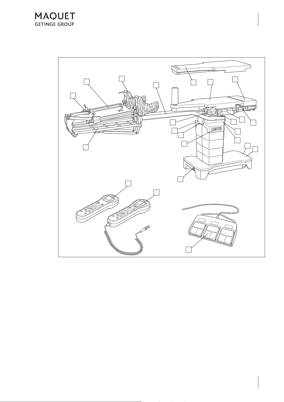
1.4 Overview
7
6
8
1
12
10
3
11
15
9
14
13
19
18
17
15
16
14
5
1a
1b
2
4
Introduction
Overview
1
Fig. 10: Overview of OR table (1433.01XX)
1 Extension device (1433.62A1), optional:
Screw tension device (1a)
Gas strut assisted height adjustment (1b)
2 Extension shoe (1003.67C0), optional
3 Traction bar (1433.61AC), optional
4 Extension plate (1433.66AC), optional
5 Extension plate (1433.66BC), optional
6 Extension plate (1131.31BC), optional
7 NORMAL mounting point
8 Basic table top
9 Release button for traction bar
10 Connection for equipotential bonding
11 Connection for mains cable
12 Service mounting point
13 Override control panel
14 Connections for corded hand control / foot
switch
15 Infrared receiver
16 REVERSE mounting point
17 IR remote control (1433.91A0), optional
18 Corded hand control (1433.90A0), optional
19 Foot switch (1009.81GX), optional
1433.01XX
GA 1433.01 EN 08
11
Page 20

Introduction
1
Basic requirements
1.5 Basic requirements
1.5.1 Use in accordance with the intended purpose
This product is an active Class I medical device
according to the Medical Device Directive
93/42/EU, which will have to be entered in the
medical device log.
In accordance with the above-mentioned
Directive, the only persons who may operate
this product are those who have been instructed, by authorised personnel, in the use of the
product.
This product is to be used exclusively in human
medicine.
Patients may be placed on the device and
brought into position only under the supervision
of medical personnel.
1.5.2 Applicable standards
The product satisfies the basic requirements
set forth in Annex I to the 93/42/EU Directive
drafted by the Medical Products Council
(Medical Device Directive) as well as the
applicable national codes and the Medical
Rooms used for medical purposes and in which
the product is used shall comply with
VDE Regulation 0100 Part 710 and/or the corresponding local codes.
Accessories
Accessories or combinations of accessories
may be utilised only when and as indicated in
these operating instructions.
Use other accessories, combinations and parts
subject to wear only if these are intended
expressly for the application and will not
adversely affect performance features or safety
requirements.
Products Act in Germany. This is certified by
compliance with harmonised standards such as
IEC 60601-1 and related standards and the
respective special sections.
12
1433.01XX
GA 1433.01 EN 08
Page 21

1.5.3 Intended purposes
1.5.3.1 Mobile operating table YUNO
Introduction
Basic requirements
1
The YUNO mobile operating table (1433.01XX)
is designed for the support and positioning the
patient for surgical treatment immediately before, during and after surgical interventions as
well as for examination and treatment.
The table top is radiolucent and enables intraoperative use of X-ray equipment. The design
of the table top makes the OR table suitable for
all surgical disciplines.
The product may only be operated by medically
trained staff within the OR environment. Any
use other than described above is deemed not
to be in accordance with the intended purpose.
The OR table can be used for an overall load of
up to 155 kg without restrictions on positions
and adjustment functions. The OR table can be
1.5.3.2 Variants
The product is available in the following versions:
• 1433.01B0
with SFC padding, side rails in EUROPE format (10 x 25 mm) and autodrive
• 1433.01F0
with SFC padding, side rails in USA format
(9.54 x 28.6 mm) and autodrive
used with restrictions with an overall table top
load between 155 kg and 454 kg.
In conjunction with the extension device
(1433.62A1), the OR table can be used without
restrictions up to 250 kg.
The OR table (1433.01XX) may not be used
under the following conditions:
• if the overall load exceeds 454 kg,
• if the overall load exceeds 155 kg, without
taking restrictions into account,
• to transport the patient within the hospital,
• with accessories which are not approved by
MAQUET,
• in rooms where MR tomographs are employed.
1.5.3.3 Product features
All materials used by MAQUET (e.g. materials
used for SFC and PUR padding, gel pads,
belts, transport belts, etc.) are latex-free.
1433.01XX
GA 1433.01 EN 08
13
Page 22

Introduction
1
Basic requirements
1.5.3.4 Hand controls
The hand controls are used to adjust the OR table.
1.5.3.5 Side rails
Side rails are used to mount approved
accessories, in accordance with the
manufacturer's instructions.
The following distinctions are made:
• Corded hand control (1433.90A0)
• IR remote control (1433.91A0)
• Foot switch (1009.81G0/G1/G2)
• Override control panel on the column (integrated into the column)
14
1433.01XX
GA 1433.01 EN 08
Page 23
2 Basic safety instructions
2.1 Personal safety notes
D ANGER!
Potentially fatal!
Hazard resulting from improper handling.
Be absolutely sure to follow the operating instructions for the operating table.
D ANGER!
Potentially fatal!
Risk caused by incorrect handling.
Please always observe the technical description for the mobile operating table.
W ARNING!
Risk of injury!
Patient may be endangered as a result of incorrect use.
Follow the operating instructions for all accessories.
Basic safety instructions
Personal safety notes
2
D ANGER!
Potentially fatal!
Danger due to unauthorised modifications.
The product may not be modified.
D ANGER!
Potentially fatal!
Vital functions can be impaired through incorrect positioning.
Position the patient correctly and maintain continuous observation.
W ARNING!
Risk of injury!
Improper positioning can be detrimental to patient health (causing bedsores, for
instance).
Always position the patient correctly and maintain continuous observation.
W ARNING!
Injury hazard!
MAQUET products may be used only when fully functional.
Check to ensure that this MAQUET product is fully functional and in good working
order prior to use.
W ARNING!
Risk of injury!
MAQUET products may be used only when properly lubricated.
Lubricate MAQUET products at regular intervals.
GA 1433.01 EN 08
1433.01XX
15
Page 24
Basic safety instructions
2
Personal safety notes
D ANGER!
Risk of explosion!
The operating table may not be used in hazardous locations (AP-M) during mains
operation.
An explosion could occur when using disinfectants or cleaning agents containing
alcohol, or flammable anaesthetics which are blended with air, oxygen or nitrous
oxide.
When operating on the mains supply, never use disinfectants or cleaning agents
containing alcohol, or flammable anaesthetics which are blended with air, oxygen
or nitrous oxide!
W ARNING!
Risk of injury!
Park the mobile operating table on level ground and secure with the [LOCK] func-
tion before each application and after each movement.
W ARNING!
Risk of injury!
Park the mobile operating table on level ground and secure with the [LOCK] func-
tion before each application and after each movement.
W ARNING!
Risk of injury due to material breakage or tipping of the OR table!
The accessories attached to the OR table may not exceed the maximum protru-
sion (protrusion = maximum distance to leg plate/back plate mounting point of the
OR table, see section on patient positioning).
The accessory can be deployed without restriction within the permitted overhang
of the OR table and up to a proportionate patient weight of 135 kg.
If the overall load is between 155 kg to maximum 454 kg, the protrusion of the OR
table and all accessories used must be authorised for such use respectively.
Please observe these specifications for positioning the patient.
W ARNING!
Risk of injury due to the OR table tipping!
With an overall load of in excess of 250 kg, do not extend the swivel castors of the
mobile operating table.
Function [UNLOCK] is not permitted.
16
W ARNING!
Injury hazard resulting from the operating table tipping!
Observe the prescribed orientation for the patient.
Do not lay the patient's upper part of the body on the leg plates.
1433.01XX
GA 1433.01 EN 08
Page 25
Basic safety instructions
Personal safety notes
W ARNING!
Risk of injury due to the operating table tipping!
If the patient is transferred to the operating table over the head end of the
operating table, the operating table may tip.
The patient may be transferred only from the side of the operating table.
W ARNING!
Risk of injury due to the operating table tipping!
If the operating table is not locked during patient transfer, the operating table may
tip.
The operating table must be locked on the floor before transferring the patient.
W ARNING!
Risk of injury!
If the patient is not secured during positioning of the OR table, when adjusting the
table top or when positioning the patient (particularly when the inclination and tilt
features are used), the patient could slip, uncontrolled, off the table top.
Always secure the patient and maintain continuous observation.
2
W ARNING!
Injury hazard!
When adjusting or moving the operating table or table top, the staff, the patient
and the accessories are exposed to pinching and shearing hazards, particularly
in the area around the joints at the head, back and leg plates.
Always ensure that no one can be subjected to pinching or shearing action or
injured in any other way and the accessories do not collide with any nearby
objects.
W ARNING!
Risk of injury!
Whenever the product is mounted and adjusted, there is a danger of pinching and
shearing to the staff, patient and accessories.
Always ensure that no one can be subjected to pinching or shearing action or
injured in any other way and that the accessories do not collide with any nearby
objects.
W ARNING!
Risk of injury!
If the individual adjustment function for a divided leg plate is activated at the joint
mounting point, although a single-piece accessory is attached to the mounting
point, the accessory may be damaged during individual adjustment in the event
of a malfunction.
Before adjusting single-piece accessories ensure that the individual adjustment
function is deactivated using the selector switch [leg side] (status LEDs for the left
and right leg side are on).
1433.01XX
GA 1433.01 EN 08
17
Page 26
Basic safety instructions
2
Personal safety notes
W ARNING!
Risk of injury!
When setting down the OR table, feet or objects lying on the floor may get pinched
or crushed.
Before setting the OR table down, make sure that there are neither feet nor any
objects underneath the column.
W ARNING!
Injury hazard!
Electrical devices (e. g. cellphones, radios, magnetic resonance tomographs) can
interfere with the functioning of the product when used near the product.
Electrical devices which can interfere with the functioning of the product may not
be used near the product.
Please observe the information concerning electromagnetic compatibility (EMC)
(radiation and resistance to interference) contained in the Technical Description.
Adhere to those specifications when using electrical devices and respond proper-
ly in the event of effects on the device or the product.
W ARNING!
Risk of burning!
Using high-frequency devices, defibrillators and defibrillator monitors exposes the
patient to burn hazard due to contact with metal components in the device or
accessories and/or if resting on wet drapes or electrically conductive padding.
Avoid any contact between the patient and metallic components; never use moist
of wet surgical drapes.
Be absolutely sure to comply with the manufacturers operating instructions!
W ARNING!
Risk of injury!
Magnetic fields of a magnitude of more than 0.5 mT may impair the function of the
product.
Never use the product within the 0.5 mT field.
W ARNING!
Risk of infection!
If the operating table is used in areas with varying hygienic requirements, there is
a risk of infection.
Treat the operating table in accordance with the hygiene guideline and the
instructions given in the chapter "Cleaning and disinfection".
18
1433.01XX
GA 1433.01 EN 08
Page 27
2.2 Safety notes for the OR table
W ARNING!
Risk of injury!
If locking elements (offset levers, handle screws, locking mechanisms etc.) are
opened, the clamps are released and the product can be moved.
Before opening the locking elements, hold the individual parts securely. Make
sure that all locking elements are closed after each adjustment procedure.
C AUTION!
Property damage!
Eliminate all potential hindrances and obstacles before moving the operating
table and avoid collisions.
C AUTION!
Property damage!
When tilting or sloping the table top or when articulating the leg plate ensure that
the table top does not collide with the column or the operating table base.
Basic safety instructions
Safety notes for the OR table
2
C AUTION!
Property damage!
Any objects left on the operating table base will damage the cladding as it moves.
Do not put any objects on the operating table base.
1433.01XX
GA 1433.01 EN 08
19
Page 28
Basic safety instructions
2
Safety notes regarding the use of accessories
2.3 Safety notes regarding the use of accessories
W ARNING!
Risk of injury due to material failure!
The side rail accessory weight may not exceed 25 kg.
The maximum permissible overall load is reduced in accordance with the weight
of the accessories attached. Never use accessories weighing more than this max-
imum.
W ARNING!
Risk of injury!
Patient may be endangered as a result of incorrect use.
Follow the operating instructions for all accessories.
W ARNING!
Risk of injury!
Accessories that are not approved by MAQUET for this product as well as acces-
sories from other manufacturers may cause injuries.
Only use MAQUET accessories that have been approved for the product.
Accessories made by other manufacturers may only be used after obtaining writ-
ten permission from MAQUET.
W ARNING!
Risk of injury!
When adjusting and moving the OR table, the table top or the accessories colli-
sions may occur with the patient, between the individual products or parts pointing
downwards.
During the adjustment procedures, always pay attention to the OR table and ac-
cessories and avoid collisions. Ensure that tubes, cables and drapes are not
trapped.
W ARNING!
Risk of injury!
Products / accessories not attached properly may loosen and cause injuries.
Always ensure that all locking elements (offset lever, setting clamps, catchs etc.)
of the product / accessory are closed and movable parts are fixed properly. Check
locking after every adjustment procedure.
C AUTION!
Property damage!
Side rail accessories with long lever arms may damage the product.
Never use accessories with long lever arms.
20
1433.01XX
GA 1433.01 EN 08
Page 29
Basic safety instructions
Safety notes regarding the use of accessories
C AUTION!
Property damage!
If accessories which are mounted to the side rail extend laterally beyond the side
rail near the table top articulations, the table top may collide with the accessories
when making table top adjustments.
When mounting accessories, be sure to observe that the accessory does not
extend laterally beyond the side rail near the table top articulations.
C AUTION!
Property damage!
Using accessories with release levers pointing downwards may cause a collision
with the traction bars during adjustment.
Observe the adjustment procedure carefully and avoid collisions.
2
1433.01XX
GA 1433.01 EN 08
21
Page 30
Basic safety instructions
2
Safety notes regarding padding
2.4 Safety notes regarding padding
D ANGER!
The patient may slip off the table if the padding is not secured properly.
Do not use padding if the Velcro straps on the padding do not line up with the
strips on the product.
Only apply padding to the product that has been authorised for use.
D ANGER!
The patient can slip off the table if the padding is not properly secured.
Worn, loose or wet loop strips will not secure the padding properly on the product.
When attaching the padding, check to ensure that it is properly affixed.
W ARNING!
Health hazard!
In the interests of hygiene the padding must be covered with sterile drapes.
C AUTION!
Property damage!
Padding may be deformed as a result of improper storage.
Padding should only stored flat.
C AUTION!
Improper use can cause property damage!
Use both hands to remove the padding.
22
1433.01XX
GA 1433.01 EN 08
Page 31

3 Operation and use
3.1 General
Operation and use
General
3
Motorised autodrive
The OR table may be moved within the OR environment by means of a motorised auto drive.
Motorised joint mounting points
The basic table top is equipped with two motoradjustable joint mounting points, the NORMAL
mounting point and the REVERSE mounting
point. The adjustment range of the joint mounting points is ±90°. Additional accessories for
patient positioning may be mounted to the joint
mounting points. These accessories may restrict the adjustment range of the joint mounting
points. For example, by mounting the back
plate (1433.33XX) the lowering function is restricted to -40°.
3.2 Acoustic signals issued by the OR table
In certain situations, the OR table outputs
acoustic signals.
Side rails
Additional side rail accessories may be mounted to the side rail of the basic table top
(
Page 125, Approved accessories). Acces-
sories and side rail accessories mounted to the
basic table top may be adjusted manually.
Operation
A corded hand control is used for the motorised
adjustments of the OR table; the OR table can
also be adjusted using an IR remote control and
a foot switch. The OR table can be controlled
using the override panel in the event of an
emergency.
Signals
Acoustic signals inform you about the status of
the OR table.
Intermittent tone
• Adjustment is at a critical stage.
• The battery of the OR table must be recharged.
Fig. 11: Acoustic signals issued by the OR table
Continuous tone
• Final position reached.
1433.01XX
GA 1433.01 EN 08
23
Page 32

Operation and use
1
3
Set up the equipotential bonding
3.3 Set up the equipotential bonding
W ARNING!
Risk of injury!
Without equipotential bonding, products with differing electrical potentials may
cause short circuits on the operating table.
Establish potential bonding prior to each use of the operating table.
N OTE
The electrical conductivity of the product has to be checked annually by an
authorized service technician.
Connect the supplied equipotential bonding
cable to the equipotential bonding pin (1) of
the mobile operating table before using.
Connect the other end of the equipotential
bonding cable to the operating room's equipotential bonding pin.
Fig. 12: Setting up equipotential bonding
24
1433.01XX
GA 1433.01 EN 08
Page 33

3.4 Mains operation / battery operation
1
2
3.4.1 Charge batteries (mains operation)
D ANGER!
Risk of explosion!
The operating table may not be used in hazardous locations (AP-M) during mains
operation.
An explosion could occur when using disinfectants or cleaning agents containing
alcohol, or flammable anaesthetics which are blended with air, oxygen or nitrous
oxide.
When operating on the mains supply, never use disinfectants or cleaning agents
containing alcohol, or flammable anaesthetics which are blended with air, oxygen
or nitrous oxide!
Operation and use
Mains operation / battery operation
3
N OTE
The operating table is disconnected from the mains by means of the plug.
Fig. 13: Establishing and separating the mains con-
nection
Connection to mains supply
Open the cover for the mains connection (1).
Connect the supplied mains cable to the mo-
bile operating table (2).
Then plug the mains plug into the mains
socket.
Green LED on the override control panel
is lit.
The rechargeable batteries in the mobile
operating table will be charged.
The plug must always be accessible to en-
sure that the OR table can be unplugged
from the mains at any time.
Detach the mains cable
Pull the plug out of the mains socket.
Detach the mains cable from the mobile op-
erating table.
1433.01XX
GA 1433.01 EN 08
25
Page 34

Operation and use
3
Mains operation / battery operation
3.4.2 Battery operation
N OTE
When battery-powered, without being connected to the mains, Class AP
explosion protection is ensured. The product may be used in areas subject to
explosion hazard, zone AP-M.
N OTE
To avoid recharging the batteries while the OR is in use, we recommend to re-
charge the batteries daily after the surgical work.
E NVIRONMENT
Defective rechargeable batteries shall be recycled as per 91/157/EEC.
Defective rechargeable batteries may not be opened, disposed of in household
waste, burned or thrown in water.
Defective rechargeable batteries must be disposed of at local collection points.
Please note:
• Fully charged rechargeable batteries will
provide power for about 1 week of OR operation (5-days of operation).
• A complete charging cycle takes about 10
hours.
• When the charge drops to below approximately 10 %, the mobile operating table will
shut down automatically.
• Recharge the batteries overnight.
• When the OR table is switched on, too low a
battery charge state will be indicated by the
error message "Charge column battery" on
an orange background on the display of the
hand control. In addition, the orange status
display LED on the OR table base flashes
when the OR table is adjusted and a fast intermittent signal sounds. When this happens, do not start a new operation.
• The rechargeable batteries are automatically
recharged as soon as the OR table is connected to the mains using the mains cable.
• After 10 days without a battery charge, at the
latest, the deep discharge protection function
of the rechargeable battery is activated. If the
deep discharge protection is active, the orange LED on the status display is not lit.
26
1433.01XX
GA 1433.01 EN 08
Page 35

3.5 Connecting the service mounting point
2
3
4
1
C AUTION!
Property damage!
The cable can be pinched when adjusting the operating table.
Ensure that the cable is not pinched.
C AUTION!
Material damage!
Risk of stumbling as a result of loosely laid cables.
Fix cables when laying in order to prevent them from becoming a stumbling haz-
ard.
Operation and use
Connecting the service mounting point
Inserting the plug
Undo the blind cap (1).
Insert the plug (2) into the socket in accord-
ance with the coding (3).
Grasp the plug at the knurl (4) and turn it in
clockwise direction until the plug is screwed
in fully.
3
Fig. 14: Connecting the service mounting point
1433.01XX
GA 1433.01 EN 08
27
Page 36

Operation and use
1
2
3
Attaching the hand control to the side rail
3.6 Attaching the hand control to the side rail
C AUTION!
Property damage!
If a hand control is attached to the side rail, it may slide along the side rail or cause
a collision between the hand control and operating table / accessories when the
table top is adjusted.
Remove the hand control from the side rail before adjusting the table top.
Attach the bracket (1) to the side rail (2).
Fig. 15: Attaching the hand control to the side rail
28
1433.01XX
GA 1433.01 EN 08
Page 37

3.7 Mechanical adjustments
3.7.1 Accessory recognition
W ARNING!
Risk of injury!
Additional accessories attached to the side rails, accessories which are not
mounted directly on the leg plate mounting point and manual adjustments (non-
motorised adjustments) of accessories will not be recognised by the collision rec-
ognition feature.
Observe the movement during the adjustment procedure and be sure to avoid any
collisions.
W ARNING!
Risk of collision!
When using the seat plate extension 1133.55B0 there is a risk of collision with the
column. The mount for the TUR drainage set and the x-ray cassette is not recog-
nised by the collision recognition on the NORMAL and REVERSE mounting
points.
If the seat plate extension 1133.55B0 is mounted to either the NORMAL or
REVERSE mounting point, the seat plate extension may not be lowered.
Operation and use
Mechanical adjustments
3
W ARNING!
Risk of collision!
When using the following accessories there is a risk of collision if these accesso-
ries are mounted to the REVERSE mounting point.
The following accessories may not be mounted to the REVERSE mounting point:
• Connection bracket (1130.54XX)
• Connection bracket (1130.62XX)
• Motor-driven head rest adjustment mechanism (1002.74XX)
• Positioning device for spinal surgery (1007.03XX)
• Adapter clamp pair (T555.6000) in conjunction with countertraction post for tibia and fibula (1003.50XX / 1004.92XX)
• Positioning device for spinal surgery (T483.0001)
1433.01XX
GA 1433.01 EN 08
29
Page 38

Operation and use
1
2
3
Mechanical adjustments
Fig. 16: NORMAL/REVERSE mounting point
General:
Whenever adjusting an accessory or the table
top module downward, there is a collision risk:
with other products in the adjustment range of
the OR table, the OR table base or the floor.
If a risk of collision is recognised the adjustment
procedure is halted as soon as mounted accessories are adjusted into the critical area. The
operating table can then only be adjusted in a
restricted adjustment mode. In addition, a collision recognition feature is shown for hand controls with display.
Pressing the adjustment function key again
within 3 seconds allows the adjustment of the
operating table to be continued with decreased
speed. An cyclical acoustic signal sounds dur-
ing the adjustment phase. The user must monitor the adjustment constantly to avoid a
possible collision with the operating table foot
or the floor.
The collision recognition feature can only recognize accessories that are directly attached to
the leg plate mounting point, i.e. no side rail accessories and accessories that can only be
connected to the leg plate mounting point by
using a further accessory.
The user must pay special attention to the accessory that is not recognized by the collision
recognition feature when adjusting the OR table.
30
1433.01XX
GA 1433.01 EN 08
Page 39

Fig. 17: Accessory recognition
1
Operation and use
Mechanical adjustments
The leg plate mounting point is fitted with accessory recognition.
In the event of the use of coded accessories at
the leg plate mounting point, the dimensions of
the accessories are recognised and evaluated
by the OR table. The adjustment range of a
coded accessory is defined in accordance with
the dimensions of the accessories. Coded accessories are marked by a "Code Plug" (1) located on the end of the mounting pin.
In the event of the use of uncoded accessories
at the leg plate mounting point, the dimensions
of the accessories are not recognised and are
not evaluated by the OR table.
The restricted adjustment range may be very
large, since accessories with the most critical
dimensions are considered for the accessory
recognition.
3
1433.01XX
GA 1433.01 EN 08
31
Page 40

Operation and use
2
1
3
3
Mechanical adjustments
3.7.2 Mounting and removing table width extensions (1001.75A0/76A0)
W ARNING!
Risk of injury!
Material failure.
The following accessories may be mounted to the table width extensions
1001.75A0 and 1001.76A0:
• 1x infusion stand 1009.01C0
• 1x anaesthesia screen 1002.57A0
• 1x wristlet 1002.24C0
• 1 x arm protector 1002.25A0
The patient must lie above the centre of the column (lateral direction).
W ARNING!
Risk of injury!
Material failure.
Further OR table width extenders may not be mounted to the table width extend-
ers 1001.75A0 and 1001.76A0.
Fig. 18: Table width extenders
Attach / remove OR table width extenders
Attach the clamp (1) of the OR table width
extension to the side rail (2).
Tighten the locking lever (3).
Check firm seat of the OP table width exten-
sion.
32
1433.01XX
GA 1433.01 EN 08
Page 41

3.7.3 Mounting/removing the head rest
2
2
1
1
Operation and use
Mechanical adjustments
3
Head rests may be connected using the extension plate (1131.31XX) or the head rest adapter
(1130.81A0) to both NORMAL / REVERSE
mounting points of the table top.
N OTE
Use and handling are described in detail in the operating instructions for this
product.
N OTE
The head plate adapter 1130.81A0 is required to mount head plates at the
NORMAL and REVERSE mounting points.
3.7.3.1 Mounting and removing the head rest using the head rest adapter (1130.81A0)
N OTE
The head plate adapter consists of a left and a right part.
If the adapters are mixed up, the distance of the drilled holes will not match up.
Observe the markings L and R.
Mounting the head rest
Insert the two head rest adapters 1130.81A0
(1), using their pins, as far as they will go into
the mounting sockets (2) at the front of the
table top.
Fig. 19: Mount the head rest adapter
1433.01XX
GA 1433.01 EN 08
33
Page 42

Operation and use
3
4
5
5
5
3
3
Mechanical adjustments
Fig. 20: Mounting the head rest
Insert the head rest (3) pins as far as they will
go into the mounting sockets (4) at the front
of the table top.
Fig. 21: Mounting and securing the head rest
Tighten the locking screws (5).
Pull on either side of the component to en-
sure that it is properly secured.
Removing the head rest
Loosen the locking screws (5).
Remove the head rest (3).
Remove the two head rest adapters
1130.81A0 (1).
34
Fig. 22: Removing the head rest
1433.01XX
GA 1433.01 EN 08
Page 43

3.7.4 Mounting and removing the extension plate (1131.31XX)
1
2
1
2
The table top can be extended to enable the positioning of taller patients or to optimise the patient position.
Mounting the extension plate
If necessary, remove the head rest
(
Page 33).
Insert the extension plate (1) pins fully into
the mounting sockets (2) on the front of the
table top.
The extension plate is locked automatical-
ly.
Check the secure fit of the extension plate.
Operation and use
Mechanical adjustments
3
Fig. 23: Mounting the extension plate
Removing the extension plate
Press the two release levers (1) against the
extension plate.
Pull the extension plate (2), without tilting,
out of the front holes of the table top.
Fig. 24: Removing the extension plate
1433.01XX
GA 1433.01 EN 08
35
Page 44

Operation and use
1
2
3
1
3
Mechanical adjustments
3.7.5 Seat plate extension
The table top is extended to position taller patients or to optimise the patient position.
3.7.5.1 Mounting and removing the seat plate extension (1131.55XX)
Mounting the seat plate extension
If necessary, remove the leg plate or transfer
board.
Insert the pins of the seat plate extension (1)
fully into the front openings (2) of the table
top.
The seat plate extension is locked auto-
matically.
Pull on both sides of the component to en-
sure that it is properly secured.
Fig. 25: Mounting the seat plate extension
Fig. 26: Removing the seat plate extension
Removing the seat plate extension
If necessary, remove the leg plate or transfer
board.
Press both levers (3) up against the seat
plate extension.
Pull out the seat plate extension (1) without
tilting.
36
1433.01XX
GA 1433.01 EN 08
Page 45

3.7.6 Leg plates
2
3
1
4
Leg plates can be mounted on both the
NORMAL / REVERSE mounting points.
3.7.6.1 Mounting and removing the pair of leg plates (1133.53BC)
Mounting the pair of leg plates
Press and hold the release button (1).
Insert the pins (3) of the leg plate (2) into the
mounting sockets (4) at the front of the table
top as far as they will go.
Release the release button (1).
Check locking by pulling the leg plate.
Leg plate is locked.
Mount the second leg plate in the same way
as for the first leg plate.
Operation and use
Mechanical adjustments
3
Fig. 27: Mounting the pair of leg plates
Removing the pair of leg plates
Press and hold the release button (1).
Pull out leg plate without tilting.
Release the release button.
Remove the second leg plate in the same
way as the first leg plate.
Fig. 28: Removing the pair of leg plates
1433.01XX
GA 1433.01 EN 08
37
Page 46

Operation and use
2
1
2
1
3
Mechanical adjustments
3.7.6.2 Mounting and removing the leg plate (1133.58BC)
The single-section leg plate is suitable for surgical procedures in orthopaedic and vascular
surgery where the patient's legs are to be X-
Fig. 29: Mounting the leg plate
rayed. The slope of the leg plate is adjusted using the motorised hand control.
Mounting the leg plate
Push the release lever (1) in the direction in-
dicated by the arrow.
Insert the leg plate (2) pins into the mounting
sockets at the front of the table top as far as
they will go.
Release the release lever.
Check locking by pulling the leg plate on both
sides.
Leg plate is locked.
Removing the leg plate
Pull the release lever (1) in the direction indi-
cated by the arrow.
Pull the leg plate (2) out of the mounting hole
of the table top without tilting it.
38
Fig. 30: Removing the leg plate
1433.01XX
GA 1433.01 EN 08
Page 47

3.7.7 Basic table top
1
2
3
1
2
3
3.7.7.1 Mounting/removing the standard plate
Operation and use
Mechanical adjustments
Mounting the standard plate
Position the standard plate (1) in such a way
that the pins (2) lie on the mounts (3) on the
column.
Firmly push down the standard plate.
The standard plate engages.
3
Fig. 31: Mounting the standard plate
Fig. 32: Removing the standard plate
Removing the standard plate
Hold and lift the standard plate (1) on the
side with a single fixing point (2).
Grasp and lift the standard plate on the side
with two fixing points (3) and remove.
1433.01XX
GA 1433.01 EN 08
39
Page 48

Operation and use
3
5
4
1
2
1
2
3
3
Mechanical adjustments
3.7.7.2 Mounting / removing the extension plate (1433.66XC)
The extension plate is available in the following
versions:
• 1433.66AC:
Extension plate with three positions for the
countertraction post
• 1433.66BC:
Extension plate with one position for the
countertraction post
• 1433.41BC
Table top for extension
(Material: stainless steel)
Mounting the extension plate
On both sides, insert the pins (1) of the ex-
Set down the extension plate (3).
Pull on both sides of the component to en-
tension plate into the sockets (2) on the table
top.
The pins (4) on both sides are in the sock-
ets (5).
The extension plate engages.
sure that it is properly secured.
Fig. 33: Mounting the extension plate
Fig. 34: Removing the extension plate
Removing the extension plate
Pull and hold the release lever (1).
Lift one side of the extension plate (2).
Pull the extension plate (2) out of the socket
(3).
40
1433.01XX
GA 1433.01 EN 08
Page 49

Operation and use
3
1
2
1
2
3
4
Mechanical adjustments
3.7.8 Mounting and removing the filler pieces for the pair of leg plates (1433.50AC)
3
When using the extension plate with a single
position for the counter traction post
(1433.66BC) together with the pair of leg plates
(1433.50AC), filler pieces must be mounted for
more comfortable positioning.
Fig. 35: Mounting the filler piece
Accordingly, when using the extension plate
with three positions for the counter traction post
(1433.66AC), the filling pieces must be removed.
Mounting the filler pieces
Insert the filler piece (1) from the side into the
square socket (2) on the leg plate (3).
The filler piece engages.
Pull on the component to ensure that it is
properly secured.
Mount the second filler piece in the same
way as the first.
Removing the filler pieces
Pull and hold the locking element (1).
Pull the filler piece (2) out of the square sock-
et (3) of the leg plate (4).
Remove the second filler piece in the same
way as the first.
Fig. 36: Removing the filler piece
1433.01XX
GA 1433.01 EN 08
41
Page 50

Operation and use
3
Padding
3.8 Padding
The electrically conductive SFC padding is
fixed to the table top with Velcro straps and can
be detached.
Remove pads
Pull SFC padding with both hands from the
surface.
Fig. 37: Removing the padding
42
1433.01XX
GA 1433.01 EN 08
Page 51

4Hand controls
4.1 General
Hand controls
General
4
The operating table system can be adjusted using the following hand controls:
• IR remote control (1433.91A0)
• Corded hand control (1433.90A0)
• Foot switch (1009.81G0/G1/G2)
• Override control panel at the column
N OTE
When simultaneously operating with more than one hand device, the corded hand
devices (corded hand control, foot switch and override control panel) have priority
over the infrared hand controls (IR hand control).
When simultaneously operating hand controls of equal priority, the adjustment of
the OR table may be interrupted or stopped.
N OTE
When using the IR remote control, the signal may be interrupted by, for example,
shadowing. In this case you should change the position of the remote control or
the distance between the operating table and the IR remote control and repeat the
procedure.
N OTE
The speed of adjustment is a function of the total load.
At high total load, the speed of downward movement increases whereas the
speed of the upward movement is reduced.
As a general principle, do not operate the OR
table with two hand controls at the same time.
1433.01XX
GA 1433.01 EN 08
43
Page 52

Hand controls
4
Override control panel
4.2 Override control panel
The override control panel is used in emergencies. If there are any malfunctions or if the
corded hand control is defective, then the
mobile operating table can be controlled using
N OTE
If the batteries in the mobile operating table are exhausted, then the override
control panel will only operate when the table is connected to the mains.
N OTE
To execute a function, press and hold the ON button. Then press the appropriate
function button until the desired position is reached.
N OTE
The status display "Activate LOCK status" and "Activate UNLOCK status" are
only active when the control device or the override control panel is switched on.
The status display will flash while the operating table is adjusted to LOCK or
UNLOCK status.
N OTE
Setting the patient orientation is necessary to ensure correct adjustment of the ta-
ble top (
be previously adjusted by means of the IR remote control or the corded hand con-
trol.
Page 62, NORMAL/REVERSE patient orientation). This setting must
the override control panel.
The override control panel is located on the
upper column casing.
44
1433.01XX
GA 1433.01 EN 08
Page 53

4.2.1 Overview of override control panel
21 3 5 7 8 9 10 11
16 15 14 13 121718
4 6
Hand controls
Override control panel
4
Fig. 38: Override control panel
1 Status indicator Network connection
Fig. 39:).
(
2 Status indicator Battery charge status
(
Fig. 39:).
3 Status display Activate LOCK status
(Fig. 39:).
4 LOCK
Operating table is locked.
5 Status display Activate UNLOCK status
(
Fig. 39:).
6 UNLOCK
Operating table on castors (can be moved).
7 TREND.
Trendelenburg position (head down).
8 UP
Raising table top.
9 REV.
Reverse Trendelenburg (foot down).
10 LEG UP
Raising leg plate.
11 BACK UP
Raising back plate.
12 BACK DN
Lowering back plate.
13 LEG DN
Lowering leg plate.
14 TILT R.
Tilt right.
15 DOWN
Lowering table top.
16 TILT L
Tilt to the left.
17 0-position
Tilt and slope return to zero position.
18 ON
Activates the operating table.
Must be pressed in addition to any function key.
1433.01XX
GA 1433.01 EN 08
45
Page 54

Hand controls
4
Override control panel
4.2.2 Overview of displays
4.2.2.1 Overview of status display mains operation
Symbol Meaning
Network connection
Fig. 39: Overview of the status display for mains operation
4.2.2.2 Overview of the status display for battery operation
Symbol Meaning Colour Condition Status
Battery charge
level
Fig. 40: Overview of the status display for battery operation
LED
colour
Green Continu-
- Off Battery operation
Orange Continu-
- Off In mains operation: OR table in standby
Condition Status
Mains operation, rechargeable battery is
ous light
ous light
Flashing
light
Fast flashing light
Fast flashing light
charged
(Mains cable is connected to the OR table
and the mains supply.)
(mains cable is not connected to the OR table.
Mains cable is not connected to the mains
supply.)
In mains operation: OR table is activated
In rechargeable battery operation: Charge
capacity sufficient for battery operation
In rechargeable battery operation: Charging
capacity is insufficient for further use of rechargeable battery operation, see section
Charge batteries (mains operation). A signal
tone is sounded with the flashing light.
In rechargeable battery operation: Rechargeable battery is empty, no additional
adjustments are possible. Batteries have to
be recharged. See Charge batteries (mains
operation). A signal tone is sounded with the
flashing light.
In rechargeable battery operation: OR table
in standby mode without deep discharge of
the rechargeable battery.
mode.
In rechargeable battery operation: Deep discharge protection of the rechargeable battery has been activated, no further
adjustments possible. Batteries have to be
recharged. See Charge batteries (mains operation).
46
1433.01XX
GA 1433.01 EN 08
Page 55

4.2.2.3 Overview of change display LOCK / UNLOCK
Symbol Meaning Colour Condition Status
LOCK Blue Flashing
light
UNLOCK OR table is put on castors
Fig. 41: Overview of change display LOCK / UNLOCK
Hand controls
Override control panel
OR table is immobilised
4
1433.01XX
GA 1433.01 EN 08
47
Page 56

Hand controls
1
2
3
4
5
6
4
Corded hand controls
4.3 Corded hand controls
4.3.1 Foot switch (1009.81G0/G1/G2)
N OTE
Setting the patient orientation is necessary to ensure correct adjustment of the ta-
ble top (
be previously adjusted by means of the IR remote control or the corded hand con-
trol.
Page 62, NORMAL/REVERSE patient orientation). This setting must
N OTE
The foot switch cannot be used to cancel the two control functions "Lock operating
taple" and "Lock operating table top".
The footswitch (1009.81G0/G1/G2) is connected to the column head (
The functions of the rocker switches (1) to (4)
(
Fig. 42) are identical for all versions of the
Fig. 42: Footswitch
Page 49, Fig. 4.3.3).
footswitch. The rocker switches (5) and (6)
(
Fig. 42) have different functions for each
version.
Rocker switches (1) to (4)
1. Table top down
2. Table top up
3. Reverse Trendelenburg
4. Trendelenburg
Rocker switch (5)
• Footswitch version 1009.81G0:
Back plate, down.
• Footswitch version 1009.81G1:
Lateral tilt, left.
• Footswitch version 1009.81G2:
Leg plate, down.
Rocker switch (6)
• Footswitch version 1009.81G0:
Back plate, up.
• Footswitch version 1009.81G1:
Lateral tilt, right.
• Footswitch version 1009.81G2:
Leg plate, up.
4.3.2 Corded hand control (1433.90A0)
The button assignment (
operation of the corded hand control are identical to those of the IR remote control.
1433.01XX
48
GA 1433.01 EN 08
Page 50) and the
The corded hand control can be attached to the
column.
Page 57

4.3.3 Connecting corded hand controls
2
3
1
1
C AUTION!
Property damage!
The cable can be pinched when adjusting the operating table.
Ensure that the cable is not pinched.
C AUTION!
Material damage!
Risk of stumbling as a result of loosely laid cables.
Fix cables when laying in order to prevent them from becoming a stumbling haz-
ard.
Hand controls
Corded hand controls
The socket for corded hand controls (1) for the
corded hand control and foot switch are located
on the front of both sides of the column.
4
Fig. 43: Connecting corded hand controls
Connecting corded hand control
Open the lid of the socket for corded hand
control (2).
Insert the plug (3) into the socket for corded
hand control in accordance with the coding.
Check the correct seat of the corded hand
control plug.
1433.01XX
GA 1433.01 EN 08
49
Page 58

Hand controls
1
2
3
5
6
9
10
11
13 24
23
14
15
17
18
20
22
4 16
12
21
19
8
7
4
IR remote control (1433.91A0)
4.4 IR remote control (1433.91A0)
4.4.1 Control buttons and functions
1 Display
Lights up when a key is pressed.
2 Menu navigation key
Navigating within the menus.
3 Multi-function key
Selects the displayed function or
skips to the next higher menu.
4 Moving forwards
(corded hand control only).
5 Press LOCK
key longer than 1 second:
Swivel castors retracted, OR table is
immobilised.
6 BACK DN.
Lowers the back plate.
7 LEG SIDE
Sets the adjustment mode of the pair
of leg plates.
8 Status LED
Right leg side.
9 LEG DN.
Lowers the leg plate.
10 TREND.
Trendelenburg position
(head down).
11 TILT L.
Tilts to the left.
12 DOWN
Lowering table top.
13 MEMORY
Open [Fast storage] menu.
14 Menu navigation key
Navigating within the menus.
15 Multi-function key
Selects the displayed function or
skips to the next higher menu.
16 Moving backwards
(corded hand control only).
17 Press UNLOCK
longer than 1 second:
Swivel castors will be extended, OR
table can be displaced.
18 BACK UP
Raises the back plate.
19 Status LED
Left leg side.
20 LEG UP
Raises the leg plate.
21 UP
Raising table top.
22 REV.
Reverse Trendelenburg
(foot down).
23 TILT R.
Tilts to the right.
24 LEVEL
0-position
(table top moves to the horizontal position).
Fig. 44: Control buttons of the corded hand control (1433.90A0) and IR remote control (1433.91A0)
50
1433.01XX
GA 1433.01 EN 08
Page 59

4.4.1.1 Switching on the illumination
1
N OTE
The illumination can be activated only if the [Illumination ON] function is selected
in the [Settings] menu (
N OTE
The illumination can be activated using any button. Always use the [LOCK] button
to prevent unintentional modifications to the operating table.
Page 66).
Hand controls
IR remote control (1433.91A0)
Press the [LOCK] (1) button for approximately 1 second.
Keyboard and display are lit.
4
Fig. 45: Switching on the illumination
1433.01XX
GA 1433.01 EN 08
51
Page 60

Hand controls
1
3
2
4
IR remote control (1433.91A0)
4.4.1.2 [Leg side] selector key
The [Leg side] selector key (1) is used to set the
adjustment mode for the leg plates.
The following modes can be selected using the
[Leg side] selector key:
• Both leg plates can be adjusted together,
status LEDs for the left (2) and right (3) [Leg
side] light up
• Left leg plate can be adjusted,
status LED for left (2) [Leg side] lights up
• Right leg plate can be adjusted,
status LED for right (3) [Leg side] lights up
Fig. 46: [Leg side] selector key
52
1433.01XX
GA 1433.01 EN 08
Page 61

4.4.2 Special features of the IR remote control (1433.91A0)
4.4.2.1 General
Hand controls
IR remote control (1433.91A0)
4
The IR remote control is equipped with powerful
batteries which enable adjustments for several
days.
4.4.2.2 Acoustic signals
Fig. 47: Acoustic signals of the IR remote control
4.4.2.3 IR code
The IR remote control is uniquely assigned to a
single OR table by way of the electronic encoding.
The batteries are recharged in the charging unit
Page 56, Fig. 51).
(
Acknowledgement tone
• Function is activated.
Intermittent tone
• Function is activated for a longer period of
time.
Continuous tone
• Button has not been depressed sufficiently.
The IR code is shown on the display in the [System information] menu item (
Page 62).
4.4.2.4 Transmission power
The transmission power of the IR remote control is sufficient to operate the draped operating
table from a greater distance. If the operating
table does not execute the desired adjustment
even though the button is depressed completely (status symbol for signal transmission between operating table and IR remote control
E NVIRONMENT
Defective rechargeable batteries shall be recycled as per 91/157/EEC.
Defective rechargeable batteries may not be opened, disposed of in household
waste, burned or thrown in water.
Defective rechargeable batteries must be disposed of at local collection points.
Page 58)does not appear), then you should
(
re-aim the IR remote control or slightly move to
another position in the OR. In this event the IR
receiver at the column is being blocked (by a
person, for instance).
The batteries may also cause weak signal
transmission (
Page 56).
1433.01XX
GA 1433.01 EN 08
53
Page 62

Hand controls
1
2
3
4
IR remote control (1433.91A0)
4.4.2.5 Charging unit (1009.70A0) / Charging station (1009.71A0)
D ANGER!
Potentially fatal!
Electric shock!
Never open the product.
The batteries for the IR-remote control are
recharged in the charging unit or the charging
station. The following versions are available:
• Mobile charging unit (1009.70A0)
for A.C. voltage from 100 V to 240 V,
• Stationary charging station (1009.71A0)
for 24 V D.C. voltage; wall-mounted.
4.4.2.6 Mobile charger (1009.70A0)
D ANGER!
Potentially fatal!
Electric shock!
Check to ensure that the available mains voltage corresponds with the specifica-
tions on the type plate before connecting the mains power plug.
The product can only be separated from the power supply by unplugging at the
socket.
D ANGER!
Potentially fatal!
No explosion protection!
The product must not be used in areas subject to explosion protection.
Mounting country-specific mains adapters
Check to make sure that the available mains
voltage corresponds to the value on the type
plate.
Insert the appropriate adapter for the mains
socket into the mains adapter:
- For Europe (1)
- For USA / Japan (2)
- For Great Britain (3)
54
Fig. 48: Mounting the mains adapter
1433.01XX
GA 1433.01 EN 08
Page 63

Fig. 49: Insert the mains adapter
1
1
Hand controls
IR remote control (1433.91A0)
Insert the mains adapter into the power sock-
et
The green LED (1) lights up.
The charging unit is ready for operation.
4
4.4.2.7 Stationary charging station
Fig. 50: Stationary charging station
The stationary charging station (1) is wallmounted and powered via the wall installation.
The stationary charging station is ready for
operation when the green LED lights up.
1433.01XX
GA 1433.01 EN 08
55
Page 64

Hand controls
4
2
1
3
1
2
3
4
IR remote control (1433.91A0)
4.4.2.8 Inserting the IR remote control
N OTE
When not in use we recommend to place the IR-remote control in the charging
unit in order to avoid that the batteries are exhausted during surgery.
Hold the IR remote control (1) in the correct
position and insert it into the charger (2).
The locking tab (3) engages audibly.
The IR remote control sits in the holder.
Insert the IR remote control fully into the
charging unit.
The IR remote control will engage.
The orange LED (4) lights up.
IR remote control is charged.
Fig. 51: Recharging the IR remote control
4.4.2.9 Removing the IR remote control
Fig. 52: Removing the IR remote control
Grasp the IR remote control near the display
(1) and pull it out of the charger (2). At the
same time, hold at the upper end (3) of the
mobile charging unit.
Remove the IR remote control from the
charging unit, by pulling up at an angle.
56
1433.01XX
GA 1433.01 EN 08
Page 65

4.5 Display
3
2
1
4.5.1 General
Hand controls
Display
N OTE
When using the IR remote control, the signal may be interrupted by, for example,
shadowing. In this case you should change the position of the remote control or
the distance between the operating table and the IR remote control and repeat the
procedure.
4
Information, patient positions and adjustments
can be recalled or changed in the display.
When you activate the hand control, the most
recently called menu will be shown.
4.5.2 Display design
The display includes the following menus:
• Menu [Main menu]
• Standard patient positions (
• Menu item [System information]
(
Page 62)
• Menu [Patient positions]
(
Page 63)
• Menu [Settings] (
• Menu [Service] (
• Menu [Fast memory] (
The display is designed as follows:
1. Status bar
2. Menu window
3. Navigation bar
Page 66)
Page 66)
Page 69)
Page 60)
Fig. 53: Display design
1433.01XX
GA 1433.01 EN 08
57
Page 66

Hand controls
4
Display
4.5.3 Symbols for status bar
Symbol Meaning
The symbol indicates that the control device is receiving signals from the operating
table
(this can be used to evaluate the signal connection).
This symbol indicates that the NORMAL patient orientation function is activated.
This symbol indicates that the REVERSE patient orientation function is activated.
This symbol indicates that the operating table lock is activated.
This symbol indicates that the table top lock is activated.
This symbol indicates that the rechargeable batteries in the operating table are being charged.
This symbol indicates the charged state of the rechargeable batteries of the operating table.
This symbol indicates the charged state of the rechargeable batteries in the IR remote control.
Fig. 54: Symbols for the status bar
58
1433.01XX
GA 1433.01 EN 08
Page 67

4.5.4 Symbols for the navigation bar
1
2
3
4
5
Hand controls
Display
The navigation bar (1) shows the functions of
the multifunction buttons (2) and (3) and the
menu navigation buttons (4) and (5).
4
Fig. 55: Control buttons for the display
Symbol Meaning
This symbol shows that the left menu function is selected or the menu window is
scrolled to the left when the menu navigation button is pressed.
This symbol shows that the right menu function is selected or the menu window is
scrolled to the right when the menu navigation button is pressed.
This symbol shows that the menu function is scrolled up when the menu navigation
button is pressed.
This symbol shows that the menu function is scrolled down when the menu navigation
button is pressed.
This symbol shows that selected menu function is selected / confirmed when the multifunction button is pressed.
This symbol shows that you return to the menu on the next higher level when the multifunction button is pressed.
Fig. 56: Symbols for navigation bar
1433.01XX
GA 1433.01 EN 08
59
Page 68

Hand controls
1
4
3
2 A B
4
Display
4.5.5 Standard patient positions
All standard patient positions are listed below.
The buttons (A) and (B) can be used to scroll to
the subsequent function.
4.5.5.1 FLEX / REFLEX position
Fig. 57: FLEX / REFLEX position
Setting the FLEX position (1)
Press the multifunction button (2) and hold it
for as long as you wish to execute this function.
The table top will be inclined with the foot
down.
The back plate will be inclined with the
head down.
When the final position is reached this is
shown on the display and an acoustic signal sounds.
Release the multifunction button.
Setting the REFLEX position (3)
Press the multifunction button (4) and hold it
for as long as you wish to execute this function.
The table top will be inclined with the head
down.
The back plate is raised.
When the final position is reached this is
shown on the display and an acoustic signal sounds.
Release the multifunction button.
60
1433.01XX
GA 1433.01 EN 08
Page 69

4.5.5.2 BEACH CHAIR / BACK HORIZONTAL position
2
1
4
3
Hand controls
Display
BEACH CHAIR (1) position
Press the multifunction button (2) and hold it
for as long as you wish to execute this function.
Back plate and leg plate will be adjusted.
When the final position is reached this is
shown on the display and an acoustic signal sounds.
Release the multifunction button.
4
Fig. 58: BEACH CHAIR /
BACK HORIZONTAL position
BACK HORIZONTAL (3) position
Press the multifunction button (4) and hold it
for as long as you wish to execute this function.
The motor-power adjustable back plate is
aligned horizontally – without adjusting the
lateral tilt and inclination of the basic table
top.
In extreme positions, it may no longer be
possible to align the back plate completely
using this function.
Release the multifunction button.
1433.01XX
GA 1433.01 EN 08
61
Page 70

Hand controls
3
2
1
4
5
6
1
2
4
Display
4.5.5.3 NORMAL/REVERSE patient orientation
The patient orientation is set according to the
patient's orientation on the table top (
Definition of patient orientation).
Fig. 59: NORMAL patient orientation
Page 7,
NORMAL patient orientation (1)
Select the [NORMAL patient orientation]
function using the multifunction button (2).
The black progress bar runs on the right.
The operating table system will take on
the NORMAL patient orientation when the
black progress bar has reached the right
side.
The NORMAL patient orientation (3) is
shown on the status bar.
Fig. 60: REVERSE patient orientation
4.5.6 Menu item [System information]
Fig. 61: Menu item [System information]
REVERSE patient orientation (4)
Select the [REVERSE patient orientation]
function using the multifunction button (5).
The black progress bar runs on the right.
The operating table system will take on
the REVERSE patient orientation when
the black progress bar has reached the
right side.
The REVERSE patient orientation (6) is
shown on the status bar.
The menu item [System information] indicates
the name of the hand control (1) as well as the
IR code (2).
You may choose any name for the hand control
(e.g. OR 22). The indicated IR code depends
on the hand control. The remote control indicates the IR code of the remote control and the
corded hand control indicates the IR code of the
OR table.
These items of information can be set in the
[Service] menu. The [Service] menu is described in the technical description.
62
1433.01XX
GA 1433.01 EN 08
Page 71

4.5.7 [Patient positions] menu
1
2
3 43
W ARNING!
When automatically moving to a patient position, an extreme patient position may
occur if an adjustment function, e.g. tilting, is performed too long. The patient may
slip from the table top.
When automatically moving to a patient positioning, always observe the patients
and stop the adjustment if necessary.
Reduce / avoid extreme patient positioning with the aid of a counter adjustment
function. Then move to patient position again via the menu [Patient position].
Hand controls
Display
4
Up to 10 different patient positions can be
saved and recalled in the [Patient position]
menu. Every patient position can be assigned
4.5.7.1 Select the patient position function
Fig. 62: [Patient positions] menu
an arbitrary name to allow better differentiation.
These stored patient positions can be selected
from a list.
[Patient positions] menu (1)
Press and hold the multifunction button (2)
until the list of patient positions appears.
List of patient positions
Select the required patient position with the
menu navigation buttons (3) and confirm
your selection with the multifunction button
(4).
Patient position has been selected.
Fig. 63: List of patient positions
1433.01XX
GA 1433.01 EN 08
63
Page 72

Hand controls
6
5
7
8
95
1
1
4
Display
Fig. 64: Selecting the function
4.5.7.2 Moving into patient position
Selecting the function
Select the relevant function using the menu
navigation buttons (5).
• Recall position (6) (
• Save position (7) (
• Edit name (8) (
Confirm the desired function using the multi-
functional button (9).
Press the multifunction button (1) and hold it
for as long as you wish to execute the function.
The operating table is moved into the se-
lected patient position.
Release the multifunction button.
Fig. 63),
Fig. 4.5.7.3),
Fig. 4.5.7.4),
Fig. 65: Move into patient position
4.5.7.3 Saving the patient position
N OTE
Before calling up the [Patient Positions] menu, the patient position to be stored
must be set using the hand control.
Fig. 66: Saving the patient position
Press the multifunction button (1).
The currently set operating table position
has been saved.
64
1433.01XX
GA 1433.01 EN 08
Page 73

4.5.7.4 Editing names
21 1
3
4
5
Fig. 67: Editing names
Hand controls
Display
Select character with the menu navigation
buttons (1) and confirm the selection of the
character with the multifunction button (2).
Character is indicated in the name window
(3).
Enter additional characters in the same man-
ner until the complete name is shown.
Select the enter button (4) with the menu
navigation buttons (1) and confirm the selection with the multifunction button (2) until the
operating note "settings taken over" is indicated.
The name has been saved.
The hand control menu returns to the sub-
menu "Select function"(
Fig. 4.5.7.1).
4
Deleting a character in the name window
The individual characters in the name window
can be deleted using the X-button (5).
Select the X-button (5) with the menu navi-
gation buttons (1) and confirm the selection
with the multifunction button (2).
The last character in the name window will
be deleted.
1433.01XX
GA 1433.01 EN 08
65
Page 74

Hand controls
3
5
42
1 1 6
5
3
4 4
2
1
4
Display
4.5.8 [Settings] menu
Individual settings can be saved and recalled in
the [Settings] menu (1). Additional settings,
e. g. IR code and language are integrated in the
4.5.8.1 Selecting the [Settings] menu
Fig. 68: Selecting the setting
[Service] menu. The [Service] menu is described in the technical description.
Press the [Memory] and [zero-position] but-
tons simultaneously.
The [Settings] menu will be displayed.
Select the appropriate setting using the
menu navigation buttons (1).
• Operating table lock ON / OFF
(2)(
Fig. 69),
• Table top lock ON / OFF (3)(
• Illumination ON / OFF (4)
(
Fig. 71),
• Signal tone of the column ON / OFF
(5)(
Fig. 72).
Confirm the requested setting using the mul-
tifunction button (6).
Fig. 70),
4.5.8.2 Activating and deactivating the operating table lock
The operating table lock is used to lock the column functions as well as the table top functions
to avoid the unintentional modification of the
entire system.
The active operating table lock is shown in the
status bar of the display (1) (
The operating table lock can be deactivated
temporarily for 15 seconds by simultaneously
pressing the buttons [Patient Up] and [Patient
Down] (
Fig. 69: Activating and deactivating the OR table
lock
Select the [Operating table lock ON] (2) or
Confirm the function using the multifunction
Page 58).
Page 78).
[Operating table lock OFF] (3) function using
the menu navigation keys (4).
key (5).
The function is saved.
When the operating table lock is activated,
the symbol (1) is shown on the status bar
of the display.
66
1433.01XX
GA 1433.01 EN 08
Page 75

4.5.8.3 Activating and deactivating the table top lock
5
3
4 4
2
1
Hand controls
Display
The table top lock disables the motor-powered
adjustment functions of the table top in order to
avoid unintentional adjustments to the table
top.
When the table top lock is activated this is
shown on the status bar of the display (1)
(
Page 58).
When pressing simultaneously the [Patient up]
and [Patient down] buttons, the table top lock
can be deactivated for 15 seconds(
Page 78).
4
Fig. 70: Activating and deactivating the table top lock
Select the [Table top lock ON] (2) or [Table
lock OFF] (3) function using the menu navigation keys (4).
Confirm the function using the multifunction
key (5).
The function is saved.
When the table top lock is activated, the
symbol (1) is shown in the status bar of the
display.
1433.01XX
GA 1433.01 EN 08
67
Page 76

Hand controls
3
1
2 5
4
43 3
1
2
4
Display
4.5.8.4 Switching illumination ON / OFF
Select the [Illumination ON] function (1) using the menu navigation button (2).
Confirm the function using the multifunction
key (3).
The function is saved.
The buttons and the display are illuminat-
ed brightly.
or
Fig. 71: Switching illumination on and off
4.5.8.5 Switching the signal tone at the column ON / OFF
Fig. 72: Switching the signal tone at the column on
and off
Select the [Illumination OFF] function (4) us-
ing the menu navigation button (5).
Confirm the function using the multifunction
key (3).
The function is saved.
The buttons are not illuminated and the
display's illumination is dimmed.
Select the [Signal tone at the column ON] (1)
or [Signal tone at the column OFF] (2) function using the menu navigation buttons (3).
Confirm the function using the multifunction
key (4).
The function is saved.
68
1433.01XX
GA 1433.01 EN 08
Page 77

4.5.9 [Fast memory] menu
1
2
3
41
1
Hand controls
Display
4
Use the separate fast memory menu and save
the current table position or move to a
4.5.9.1 Selecting the function
Fig. 73: Selecting the function
4.5.9.2 Move into patient position
previously stored table position by pressing the
button [M].
Press the memory button.
The [Fast memory] menu will be dis-
played.
Select the relevant function using the menu
navigation buttons (1).
• Recall position (2) (
• Save position (3) (
Confirm the desired function using the multi-
functional button (4).
Press the multifunction button (1) and hold it
for as long as you wish to execute this function.
The operating table is moved into the se-
lected patient position.
Release the multifunction button.
Fig. 74),
Fig. 75),
Fig. 74: Move into patient position
1433.01XX
GA 1433.01 EN 08
69
Page 78

Hand controls
1
4
Display
4.5.9.3 Saving patient position
N OTE
The patient position to be saved must be set using the hand control before the
[Fast memory] menu is activated.
Press the multifunction button (1).
The currently set operating table position
is saved.
Fig. 75: Saving the patient position
70
1433.01XX
GA 1433.01 EN 08
Page 79

4.6 Adjustment functions
4.6.1 Moving/immobilising the OR table
W ARNING!
Risk of injury due to the OR table tipping!
With an overall load of in excess of 250 kg, do not extend the swivel castors of the
mobile operating table.
Function [UNLOCK] is not permitted.
C AUTION!
Risk of injury!
Secure the operating table before moving it (extending the castors of the operat-
ing table) to keep it from rolling away unintentionally.
C AUTION!
Property damage!
Eliminate all potential hindrances and obstacles before moving the operating
table and avoid collisions.
Hand controls
Adjustment functions
4
C AUTION!
Property damage!
When moving the operating table, guide it whith at least one hand in order to avoid
collisions.
N OTE
If a patient is lying on the operating table:
Secure the patient before moving / adjusting the operating table!
N OTE
It is recommended to adjust the operating table to an ergonomically favourable
height of up to 825 mm before moving it. This is given when only the green area
of the label is visible on the column (
Page 79).
N OTE
As of the software version 1.8 the operating table can be moved in two speed set-
tings. Operating tables with an older software version may be updated by an au-
thorised service technician.
N OTE
The floor clearance of the mobile operating table is a maximum of 10 mm with the
swivel castors extended. It is not possible to manoeuvre higher thresholds.
1433.01XX
GA 1433.01 EN 08
71
Page 80

Hand controls
4
Adjustment functions
4.6.1.1 Moving the OR table using(UNLOCK)
N OTE
The operating table can be moved in both longitudinal and transverse directions.
The swivel castors set themselves to the direction of the most recent motion. If
the column is to be moved at an angle of 90° to the most recent direction of mo-
tion, increased exertion of force is required, since the swivel castors are posi-
tioned across the desired direction of travel. If the swivel castors are positioned
across the required direction of travel, it is easier to move the operating table if
you start off diagonally to the required direction of travel (angle of approximately
45°).
The assistance of a second person might be required here.
Raising the OR table (UNLOCK) and moving
it
Remove the equipotential bonding cable and
mains cable from the OR table.
Press the [UNLOCK] button for at least 1
second.
Fig. 76: Motorised adjustment of the table top
The swivel castors extend automatically.
OR table can be moved.
Hold the OR table with at least one hand.
Press and hold the [BACKW.] or [FORW.]
button.
The OR table moves in the appropriate di-
rection at a slow speed.
Guide the OR table with at least one hand.
Release the [BACKW.] or [FORW.] button
once the table reaches the desired position.
The OR table stops moving.
72
1433.01XX
GA 1433.01 EN 08
Page 81

4.6.1.2 Standing the OR table on the floor (LOCK)
2
1
Press the [LOCK] button for at least 1 sec-
ond.
The swivel castors are retracted automat-
ically.
OR table is immobilised.
OR table can be adjusted.
4.6.2 Lowering / raising the patient (table top)
Hand controls
Adjustment functions
Lowering the table top
Press and hold the [Patient down] button (1).
The column moves downwards.
Raising the table top
Press and hold the [Patient Up] button (2).
The column moves upwards.
4
Fig. 77: Lowering / raising the table top
1433.01XX
GA 1433.01 EN 08
73
Page 82

Hand controls
2
4
1
3
4
Adjustment functions
4.6.3 Motorised adjustment of the table top
N OTE
Setting the patient orientation is necessary in order to ensure the correct adjust-
ment of the table top accessories(
N OTE
Check the status of the change-over button [Leg side] and, if necessary, adapt it
to the adjustment function before adjusting the legs.
N OTE
The adjustment of an individual leg plate of the pair can only be carried out with
coded pairs of leg plates.
Page 62).
Fig. 78: Motorised adjustment of the table top
Back down / up
Press and hold the [Back down] button (1).
The back plate will be lowered.
Press and hold the [Back down] button (2).
The back plate will be moved up.
Leg plate down / up
Press and hold the [Leg down] button (1).
The leg plate will be lowered.
Press and hold the [Leg up] button (2).
The leg plate will be moved up.
74
1433.01XX
GA 1433.01 EN 08
Page 83

4.6.4 Aligning the patient horizontally
W ARNING!
Injury hazard!
When aligning the leg plate, especially when using knee crutches, the patient may
be injured.
When aligning the leg plate, check the patient's position and adapt it, if necessary.
N OTE
The manual adjustment functions (head and leg plates) will not be aligned.
Press the [zero-position] button and hold it
for as long as you wish to execute this function.
Hand controls
Adjustment functions
4
Lateral tilt will be reset.
Inclination is removed.
The back plate is aligned.
When the final position is reached this is
shown on the display and an acoustic signal sounds.
In the interests of safety, the leg plate and
/ or the knee crutches are not yet aligned.
Release the [zero-position] button.
Check the patient's position and adapt it, if
necessary.
Press the [zero-position] button again and
hold it for as long as you wish to execute this
function.
The leg plate is aligned.
The table top is aligned horizontally.
When the final position is reached this is
shown on the display and an acoustic signal sounds.
Release the [zero-position] button.
1433.01XX
GA 1433.01 EN 08
75
Page 84

Hand controls
4
Adjustment functions
4.6.5 Inclining the patient
W ARNING!
Risk of injury!
If the patient is not secured during positioning of the OR table, when adjusting the
table top or when positioning the patient (particularly when the inclination and tilt
features are used), the patient could slip, uncontrolled, off the table top.
Always secure the patient and maintain continuous observation.
N OTE
Any table top adjusting process will be suspended for approx. 0.5 s when centre
position (inclination = 0°) is reached. The adjustment process will then be contin-
ued beyond the centre position.
N OTE
If the OR table is both inclined and tilted: The inclination may slightly change if the
tilt progresses further. The tilt may slightly change if the inclination progresses fur-
ther.
Table top into Trendelenburg position
Press and hold the [Trendelenburg] button.
The table top will be set to the Trendelen-
burg position.
When the final position is reached this is
shown on the display and an acoustic signal sounds.
Table top into reverse Trendelenburg position
Press and hold the [Reverse Trendelenburg]
button.
The table top will be set to the reverse
Trendelenburg position.
When the final position is reached this is
shown on the display and an acoustic signal sounds.
76
1433.01XX
GA 1433.01 EN 08
Page 85

4.6.6 Tilting the patient
21
W ARNING!
Risk of injury!
If the patient is not secured during positioning of the OR table, when adjusting the
table top or when positioning the patient (particularly when the inclination and tilt
features are used), the patient could slip, uncontrolled, off the table top.
Always secure the patient and maintain continuous observation.
N OTE
Any table top adjusting process will be suspended for approx. 0.5 seconds when
centre position (lateral tilt = 0°) is reached. The adjustment process will then be
continued beyond the centre position.
N OTE
If the OR table is both inclined and tilted: The inclination may slightly change if the
tilt progresses further. The tilt may slightly change if the inclination progresses fur-
ther.
Hand controls
Adjustment functions
4
Fig. 79: Tilting the table top laterally
Lateral tilt left / right
Press and hold the [Tilt patient to the left] but-
ton (1) or the [Tilt patient to the right] button
(2).
Depending on the selected function, the
table top moves to the left or right on the
head-foot axis.
To increase the lateral tilt angle, proceed as
follows: Press the [Tilt patient to the left] button (1) or the [Tilt patient to the right] button
(2) again.
The patient will be tilted.
An intermittent acoustic signal sounds
during the adjustment phase.
When the final position is reached this is
shown on the display and an acoustic signal sounds.
1433.01XX
GA 1433.01 EN 08
77
Page 86

Hand controls
2
1
2
1
3
4
Adjustment functions
4.6.7 Deactivating the lock function temporarily
The lock function can be activated (
in order to avoid unintentional adjustments to
the table top or the entire operating
table.(
Page 67).
Fig. 80: Deactivating the lock function temporarily
Page 66)
The lock function is shown in the status bar of
the display (
A distinction is made between the operating table lock and the table top lock function.
• The operating table lock function disables all
motor-powered adjustment functions.
• The table top lock function disables all mo-
tor-powered table top adjustment functions
(height, slope, tilt, LOCK, UNLOCK, auto-
drive remain active).
Deactivate the lock function temporarily
Press the [Patient down] (1) and [Patient up]
(2) buttons.
The lock function remains deactivated un-
til the system is switched off again.
Page 58).
4.6.8 Aligning the leg plate horizontally
The leg plate can be aligned horizontally using
the key combination leg plate adjustment and
Fig. 81: Aligning the leg plate horizontally
0-position, without adjusting the lateral tilt and
slope of the table top.
Press the [Leg plate up] key (1) or the [Leg
plate down] key (2) together with the [0-posi-
tion] key (3) and keep them pressed.
The leg plate is adjusted horizontally, with-
out adjusting the lateral tilt and inclination
of the table top.
78
1433.01XX
GA 1433.01 EN 08
Page 87

4.7 Explanation of instructions for use
1
Labels with notes on use are stuck on the operating table.
Their meanings are explained below.
4.7.1 Height for operating table lock
Hand controls
Explanation of instructions for use
For moving purposes, the operating table is at
an ergonomically favourable height if only the
green field of the label (1) is visible.
4
Fig. 82: Height for operating table lock
4.7.2 Risk of collision with traction bars
Fig. 83: Risk of collision
Using accessories with release levers that point
down may result in collisions with the extension
bars.
1433.01XX
GA 1433.01 EN 08
79
Page 88

Display notes
5
General
5 Display notes
5.1 General
If a function is actuated at the hand control, a
note may appear at the display. The display
note will disappear again two seconds after the
selected function is released.
5.1.1 Structure of display notes
The three categories are marked by a symbol
and a background colour for better distinction.
Symbol Meaning
This symbol identifies notes on use.
The notes on use have no background colour.
This symbol identifies special notes on use.
The special notes on use have a green background colour.
This symbol identifies warning notes and status messages.
The warning notes and status messages have an orange background colour.
Fig. 84: Structure of display notes
The status messages are subdivided into three
categories:
• Notes on use
• Special notes on use
• Warning notes / Status messages
5.2 Notes on operation / special notes on operation
Note on use Comment
Final position reached! –
Operating table is being initialised The operating table is being configured.
Actuate the desired adjustment function again
Invalid button combination The various adjustment functions can not be per-
formed simultaneously, e.g. the [Leg up] and the
[Leg down] buttons cannot be pressed simultaneously.
0-position has been reached (without leg
plates)
0-position has been reached The entire table top is aligned horizontally.
Data being transferred The operating table exchanges data with the hand
Setting not supported This message appears when the adjustment is not
Settings saved –
Fig. 85: Notes on operation / special notes on operation (Part 1 of 2)
Table top is aligned horizontally except for the leg
plates.
(Any longitudinal / transverse shift is aligned.)
control.
available.
after the operating table has been configured.
80
1433.01XX
GA 1433.01 EN 08
Page 89

Display notes
Notes on operation / special notes on operation
Note on use Comment
Function not available This message appears when the button has no
function in this configuration of the system.
Operating table lock activated –
Operating table top lock activated –
Lock released
Function blocked by accessories Attached table top accessories are blocking the ad-
justment function.
System is in service mode –
Height restricted If the tilting is extreme, the maximum height is lim-
ited. In order to adjust the height of the operating
table, the tilt must be reduced.
Tilt restricted If the height is extreme, the maximum tilt is limited.
In order to adjust the tilt of the operating table, the
height must be reduced.
Memory position requires a different table
configuration
Memory position is not valid Called up patient position has not been defined.
Moves to table position Moves to selected patient position.
Reducing tilt To perform the desired function, the tilt of the table
Reducing slope To perform the desired function, the slope of the ta-
0-position has been reached (horizontal) The table top is aligned horizontally.
Disconnecting the mains cable –
Place operating table on its castors (UNLOCK)
Put down operating table (LOCK) –
Reducing height –
Fig. 85: Notes on operation / special notes on operation (Part 2 of 2)
To call up this position, the patient orientation and
/ or the configuration of the table top accessories
must be adapted.
Define patient position.
or
Reading error
Inform MAQUET service.
top must first be reduced.
ble top must first be reduced.
(Possible longitudinal / transverse shift is not
aligned.)
–
5
1433.01XX
GA 1433.01 EN 08
81
Page 90

Display notes
5
Warning notes / Status messages
5.3 Warning notes / Status messages
N OTE
With every status message, the error code is displayed under the attention sym-
bol. If the error cannot be rectified, make a note of the error code and forward this
information to MAQUET Service.
Warning notes / Status messages Comment
Updating the hand control The software for the hand control must be updated.
Service message for table top
No connection to operating table
Movement stopped
System message: XXX
First level the table!
Caution! Observe further motion
Attention: Collision hazard A possible collision of the table top accessories is
Aligning the joint mounting points There is a severe deviation between the two ad-
Fig. 86: Warning notes / Status messages (Part 1 of 3)
Inform MAQUET service.
Wait five seconds until the hand control switches
off automatically.
Select the adjustment function again.
If this status message is still displayed, inform
MAQUET service.
Check the transmission power of the IR-remote
control.
Wait five seconds until the hand control switches
off automatically.
Select the adjustment function again.
If this status message is still displayed, inform
MAQUET service.
Wait five seconds until the hand control switches
off automatically.
Select the adjustment function again.
If this status message is still displayed, inform
MAQUET service.
Press the [0-position] button.
Wait five seconds until the hand control switches
off automatically.
Select the adjustment function again.
If this status message is still displayed, inform
MAQUET service.
recognised. A warning signal sounds and the adjustment is stopped. Further adjustment can be
carried out under careful observation of the adjustment procedure.
Press the button again.
Adjustment continues.
Warning signal sounds.
justment angles of the joints, making adjustment
e. g. of the back plate impossible.
Remove table top accessories that are mounted
on the joint mounting point.
Press the [0-position] button.
The joint is aligned horizontally.
82
1433.01XX
GA 1433.01 EN 08
Page 91

Display notes
Warning notes / Status messages
Warning notes / Status messages Comment
Incompatible software version Inform MAQUET service.
The battery of the IR remote control is empty
Charge the IR remote control in the charging
station.
System has stopped Operating table has stopped, e. g. due to collision.
Eliminate the cause.
Check the correct functionality of the operating
table system.
If the cause / error cannot be removed, inform
MAQUET service.
No function with IR Code 00
Service message of columns
Set the IR code of the IR remote control.
Wait five seconds until the hand control switches
off automatically.
Select the adjustment function again.
If this status message is still displayed, inform
MAQUET service.
Collision! Release the button
Release the button.
Eliminate the cause.
Check the correct functionality of the operating
table system.
If the cause / error cannot be removed, inform
MAQUET service.
Collision! Actuate [0] or [Column up]
Release the button.
Do not activate the [LEVEL] or [Table top up]
button.
Recharge the batteries of the column Battery must be recharged.
Connect to mains supply.
Extreme tilt Point of extreme tilt has been reached. Further tilt
only permitted with increased caution.
Press the button again.
Adjustment continues.
Warning signal sounds.
Accessories are not locked The attached table top accessories were recog-
nised by the operating table but the table top accessories are not locked correctly.
Check the locking mechanism.
Accessory is not recognised Table top accessories not recognised.
Check the locking mechanism.
Error in the hand control: XXX
Wait five seconds until the hand control switches
off automatically.
Select the adjustment function again.
If this status message is still displayed, inform
MAQUET service.
Fig. 86: Warning notes / Status messages (Part 2 of 3)
5
1433.01XX
GA 1433.01 EN 08
83
Page 92

Display notes
5
Warning notes / Status messages
Warning notes / Status messages Comment
Inform service
Functions restricted
Foot control not recognised
Service message on foot control
Fig. 86: Warning notes / Status messages (Part 3 of 3)
Only restricted availability of operating table functions.
Inform MAQUET service.
Wait five seconds until the hand control switches
off automatically.
Select the adjustment function again.
If this status message is still displayed, inform
MAQUET service.
Only restricted availability of operating table functions.
Wait five seconds until the hand control switches
off automatically.
Select the adjustment function again.
If this status message is still displayed, inform
MAQUET service.
84
1433.01XX
GA 1433.01 EN 08
Page 93

6 Extension positioning
1
1
3
2
4
5
6.1 Assembling the extension device
6.1.1 Mounting the extension plate (1433.66XC)
Extension positioning
Assembling the extension device
Mount the extension plate (1) (Page 40).
6
Fig. 87: Mounting the extension plate
6.1.2 Mounting the traction bars
N OTE
In combination with the traction bars, tilting is restricted to 10° and sloping to 25°
(foot low).
Insert the traction bar (1) into the mount (2).
Swivel the traction bar (1) in the mount (3).
Ensure that fingers are not trapped between
the traction bar and the extension plate.
The locking (4) engages.
Check the locking mechanism.
The locking mechanism (5) is in the 0-po-
sition.
The traction bar is fixed.
Mount the second traction bar in the same
way as the first traction bar.
Fig. 88: Mounting the traction bars
1433.01XX
GA 1433.01 EN 08
85
Page 94

Extension positioning
1
2
3
1
2
6
Assembling the extension device
6.1.3 Mounting the pair of leg plates (1433.50AC)
Insert the pins (2) of the leg plate (1) as far as
they will go into the mounting sockets (3) at
the front of the table top.
Check locking by pulling the leg plate.
Leg plate is locked.
Mount the second leg plate in the same way
as for the first leg plate.
Fig. 89: Mounting the pair of leg plates
6.1.4 Mounting the height adjustment
Fig. 90: Mounting the height adjustment
Mounting the height adjustment
Insert the gas strut assisted height adjust-
ment (1) in the mounting socket (2) of the
traction bar.
Swivel height adjustment (1) down.
The height adjustment engages.
Check the locking mechanism.
The height adjustment is fixed.
Mounting the second height adjustment
Swivel the first gas strut assisted height ad-
justment outwards.
Mount the second gas strut assisted height
adjustment in the same way as the first gas
strut assisted height adjustment.
86
1433.01XX
GA 1433.01 EN 08
Page 95

6.1.5 Mounting the screw tension device
4
5
1
3
2
1
Fig. 91: Mounting the screw tension device
Extension positioning
Assembling the extension device
Since the two screw tension device mounting
points (1) and (2) are identical, the outer screw
tension device mounting point (1) is used as example to describe how to mount the screw tension device.
The inner screw tension device mounting point
is used to position patients with a leg size of up
to 790 mm (Measured: trochanter - foot).
Depending on the position, the screw tension
device can be mounted with the metal arch facing outwards or in.
Put the screw tension device (3) on the pin
(4) of the height adjustment.
Swivel the screw tension device (4) against
the locking mechanism (5).
The screw tension device engages.
Check the locking mechanism.
The screw tension device is fixed.
Mount the second screw tension device in
the same way as the first screw tension device.
6
6.1.6 Mounting the countertraction post
Insert the countertraction post (1) fully into
the mounting hole.
Fig. 92: Mounting the countertraction post
1433.01XX
GA 1433.01 EN 08
87
Page 96

Extension positioning
2
1
3
4
6
Assembling the extension device
6.1.7 Fixing patient's leg in the extension shoe
Fig. 93: Securing the patient's leg
Secure the patient's leg in the extension
shoe.
Observe the operating instructions for the
extension shoe (1003.67X0).
If required, fix the second leg of the patient's
in the extension shoe in the same way as the
first.
6.1.8 Mounting the extension shoe (1003.67X0)
Fig. 94: Mounting the extension shoe
Push the extension shoe (1) completely on
the mounting pin on the screw tension de-
vice.
The locking mechanism (2) engages un-
derneath the safety ring (3).
If necessary, tighten the handle screw (4).
The extension shoe is secured thus pre-
venting twisting.
Check the locking mechanism.
Extension shoe is fixed.
Mount the second extension shoe in the
same way as the first.
88
Fig. 95: Mounting the extension shoe
1433.01XX
GA 1433.01 EN 08
Page 97

6.1.9 Removing the pair of leg plates
1
2
Extension positioning
Setting the extension device
Press and hold the release button (1).
Pull out the leg plate (2) out of the mount
without tilting. Ensure that fingers are not
trapped between the leg plate and the extension bar.
Let go of the release button.
Remove the second leg plate in the same
way as the first leg plate.
6
Fig. 96: Removing the pair of leg plates
6.2 Setting the extension device
6.2.1 General
W ARNING!
Risk of injury!
The clamping lever on the extension device must always be released before ad-
justing the extension device (height or abduction).
N OTE
Depending on the positioning, the screw tension device may be mounted at two
different positions.
When the leg is mounted to the outer screw tension device mounting point, the
leg is raised or lowered with constant radius.
When the leg is mounted to the screw tension device mounting point displaced
inwards, the leg is compressed or stretched during adjustment, depending on the
position of the leg. When the leg is lowered, the tension must be reduced before
adjustment.
1433.01XX
GA 1433.01 EN 08
89
Page 98

Extension positioning
1
2
5
1
6
4
3
6
Setting the extension device
6.2.2 Adjusting the height of the extension device
Fig. 97: Releasing the clamping lever
Release the clamping lever (1).
Press the release lever (2).
The length of the leg is equalised.
Hold the extension device by the right handle
(3).
Tighten the right locking lever (4).
Adjust the height of the extension device as
required.
Release the locking lever (4).
The extension device is locked.
Push the locking lever (5) of the screw ten-
sion device.
The screw tension device is engaged.
Turn the spindle (6) anticlockwise.
The leg is pre-tensioned.
If necessary, tighten the clamping lever (1).
The leg is fixed.
Mount the second extension device in the
same way as the first.
90
Fig. 98: Equalising the leg length
Fig. 99: Adjusting the height of the extension device
1433.01XX
GA 1433.01 EN 08
Page 99

6.2.3 Abducting the extension device
1
2
5
1
6
4
3
Fig. 100: Releasing the clamping lever
Extension positioning
Setting the extension device
Release the clamping lever (1).
Press the release lever (2).
The length of the leg is equalised.
Hold the extension device by the left handle
(3).
Tighten the left locking lever (4).
Abduct the extension device as required.
Release the locking lever (4).
The extension device is locked.
Push the locking lever (5) of the screw ten-
sion device.
The screw tension device is engaged.
Turn the spindle (6) anticlockwise.
The leg is pre-tensioned.
If necessary, tighten the clamping lever (1).
The leg is fixed.
Abduct the second extension device in the
same way as the first.
6
Fig. 101: Equalising the leg length
Fig. 102: Abducting the extension device
1433.01XX
GA 1433.01 EN 08
91
Page 100

Extension positioning
2
3
1
1
2
6
Setting the screw tension device
6.3 Setting the screw tension device
Pre-tension the screw tension device
If necessary, release the clamping lever (1).
Press the release lever (2) and adjust the
screw tension device as required.
Press the locking lever (3).
The screw tension device is engaged.
Pre-tension the second screw tension device
in the same way as the first screw tension
device.
Fig. 103: Pre-tension the screw tension device
Fig. 104: Adjusting the screw tension device pre-
cisely
Adjusting the screw tension device precisely
Turn the spindle (1).
The screw tension device is adjusted pre-
cisely.
If necessary, tighten the clamping lever (2).
The leg is fixed.
Adjust the second screw tension device fine-
ly in the same way as the first screw tension
device.
92
1433.01XX
GA 1433.01 EN 08
 Loading...