

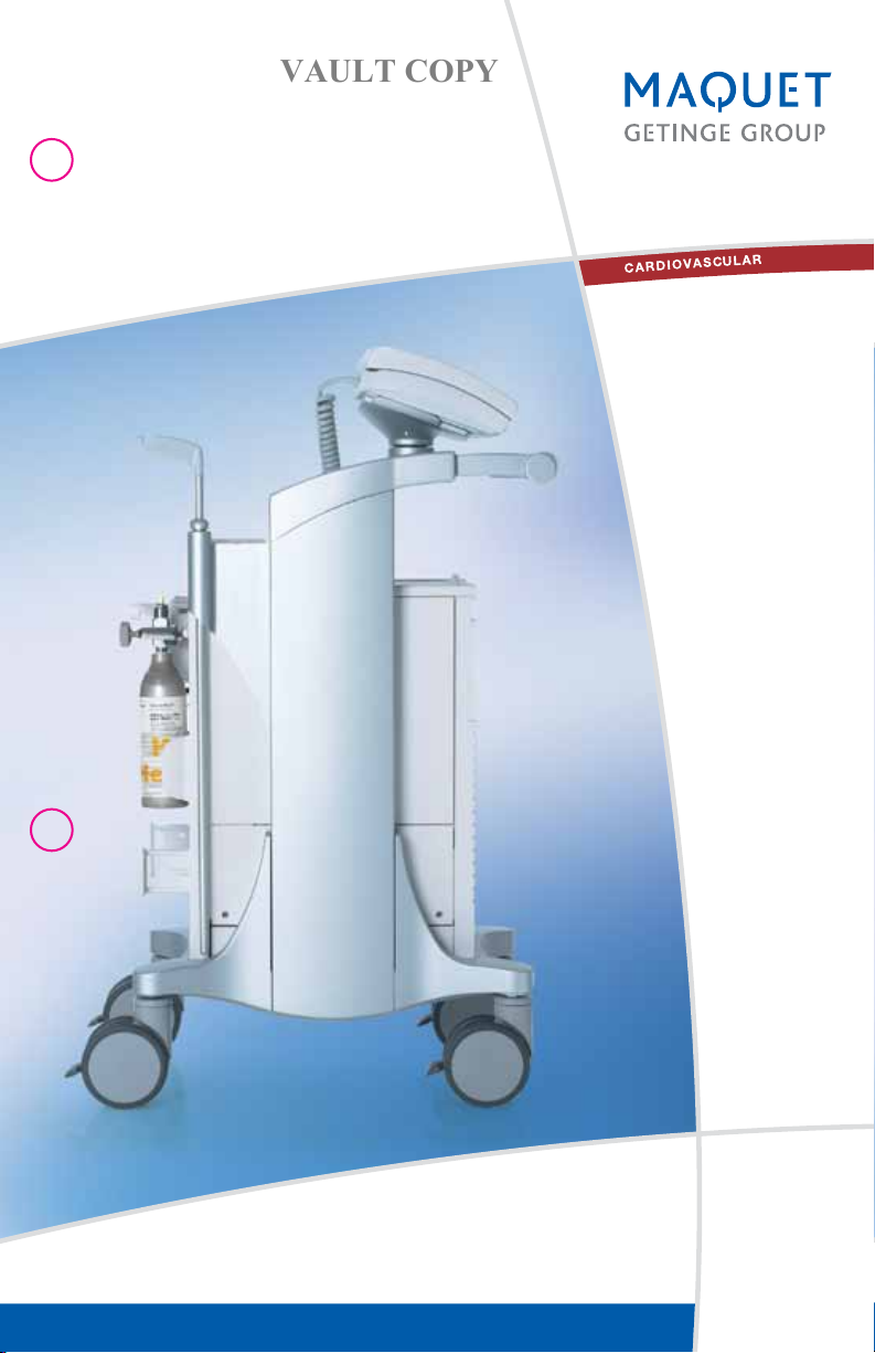
THE CS300
VAULT COPY
™
ABBREVIATED OPERATOR’S GUIDE
DATASCOPE IS NOW MAQUET CARDIOVASCULAR
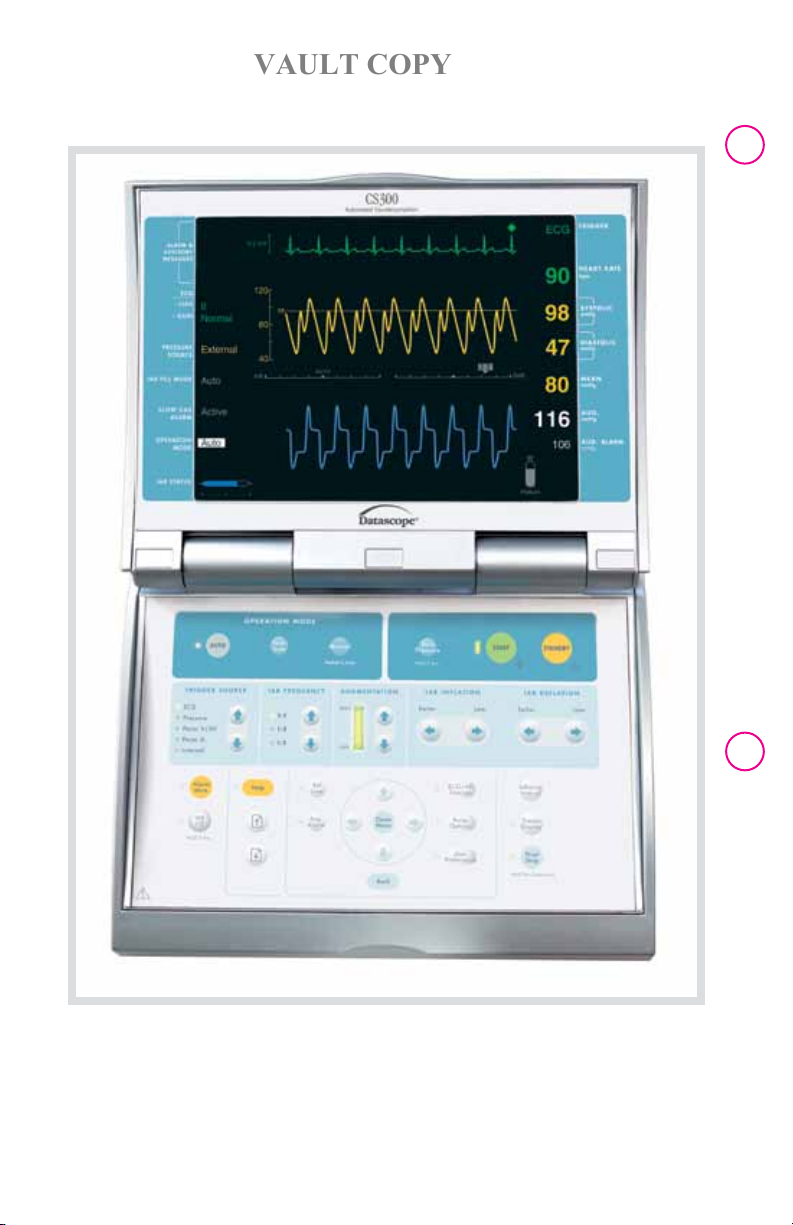
CS300 BEZEL AND KEYPAD
VAULT COPY
The CS300 provides comprehensive HELP SCREENS with easy to follow
step-by-step instructions on set-up as well as alarm and advisory conditions.

| Abbre viate d O perat or’s G uid e | C S30 0™ |
VAULT COPY
QUICK REFERENCE – INITIAL SET-UP
1. Establish power and verify the MAINS ON/OFF and the IABP ON /OFF switches are
on.
2. Open the Helium Tank.
3. Establish ECG and Pressure.
4. If using a Sensor IAB, ensure that the IAB sensor cable (orange) has been
connected.* Otherwise, zero the transducer**:
n Open the transducer to air
n Press the ZERO PRESSURE key for 2 seconds
n Close the transducer
5. Confirm that the operation mode is AUTO.
6. Attach the IAB catheter and the appropriate extender to the safety disk.
7. To initiate pumping, press the START key. In response the IABP will Autofill and then
begin pumping. If desired, IAB DEFLATION timing can be fine-tuned using the IAB
DEFLATION controls.
8. Verify the setting of the AUG. ALARM:
n Verify that the AUG. ALARM setting is approximately 10 mmHg less than
the patient’s diastolic augmented pressure.
n If needed, adjust by pressing the AUG ALARM key and using the NAVIGATION
ARROW keys to change the value displayed on the screen.
9. Initial setup is now complete.
1 |
* For Sensor IAB Calibration:
– On initial insertion, pressing the START key automatically purges and fills the IAB and
calibrates the Sensor IAB if connected.
– While assisting, press and hold the Zero Pressure key for two (2) seconds to
perform an operator-initiated calibration of the Sensor IAB. The displayed blood
pressure parameters from the IAB Sensor are only valid if the IAB Sensor is properly
calibrated.
To prevent calibration of the IAB Sensor at inappropriate times, the Zero Pressure key is
disabled when:
n The IABP is in STANDBY.
n The IAB Sensor is disconnected.
n The Pressure Source is set to External.
n The IAB Fill Mode is set to Manual Fill.
** For conventional IAB/Transducer:
– Zero the transducer as noted above
To prevent zeroing the transducer at inappropriate times, this key is disabled when:
n Pulsatility is detected on the AP waveform.
n The transducer is disconnected.
n The Pressure Source is set to External.
NOTE: A connected and functional Sensor IAB takes priority over an arterial pressure
transducer, as the Direct pressure source. The Sensor IAB must be disconnected to
activate the arterial pressure transducer input. The pump automatically searches for a
viable pressure source when multiple sources are available.

| 2
VAULT COPY
| C S300™ | Abbre viate d O perat or’s G uid e |
IAB Sensor Low Level Pressure Output – to Bedside Monitor
This output connector is used to provide an electrical signal from the IAB Sensor
module to the physiologic pressure transducer input on the patient’s bedside monitor
when a Sensor IAB is connected and calibrated. Its low level output emulates that of a
typical Arterial Pressure Transducer, allowing direct connection to the patient inputs of
the bedside monitor when a Sensor IAB is connected and calibrated.
IAB Sensor Output – Vent
This button facilitates the zeroing process required for proper calibration of the
physiologic pressure channel of an attached bedside monitor. When pressed, the IAB
Sensor Output signal will simulate that of an atmospheric vented transducer. Venting
will be simulated for 15 seconds to give users adequate time to zero the pressure
channel on the bedside monitor.
The pressure signal will then be restored automatically to permit monitoring
through the bedside and centralized monitoring systems.
OPERATING MODES
AUTO Operation Mode
All aspects of pump Operation are automated
n Most appropriate trigger source is automatically selected.
n Inflation and deflation timing is automatically set.
n Lead I, II, III, or External ECG source is automatically selected.
n System searches for the next best trigger source in the event of a loss of
trigger source.
n Timing adjusts automatically if trigger source changes, heart rate changes,
rhythm changes.
n With sustained unpredictable rhythms, R-wave deflation is automatically selected.
The message “Auto R-Wave Deflate” will be displayed. The deflation indicator
will automatically be repositioned to the far right, “R-Trac” will be displayed in the
IAB deflation indicator. The system will return to predictive timing once the rhythm
becomes predictable.
SEMI AUTO Operation Mode
n Operator selects the most appropriate trigger source.
n Operator establishes initial timing and thereafter, software algorithms automatically
track changes in patient heart rate or rhythm and adjusts timing accordingly.
n Changing the trigger source will cause the pump to go to Standby. Pumping will
resume when the START key is pressed.
n Lead I, II, III, AVR, AVL, AVF, V or External ECG source can be selected.

| Abbre viate d O perat or’s G uid e | C S30 0™ |
VAULT COPY
n With sustained unpredictable rhythms and a valid ECG Trigger, R-wave deflation
is automatically selected. The message “Auto R-Wave Deflate” will be displayed.
The deflation indicator will automatically be repositioned to the far right, “R-Trac” will
be displayed in the IAB deflation indicator. The system will return to predictive timing
once the rhythm becomes predictable.
n Loss of trigger causes an alarm and pumping will stop.
Manual Operation Mode
n Trigger source and timing of IAB inflation and deflation is determined by the operator.
n Changing the trigger source will cause the pump to go to Standby. Pumping
will resume when the START key is pressed.
n Leads I, II, III, AVR, AVL, AVF, V or External ECG source can be selected.
n Timing must be readjusted by the operator if heart rate or rhythm changes.
n Loss of trigger causes an alarm and pumping will stop.
n Manual timing is typically used for pediatric IABP patients.
WARNING: The CS300 must be in Semi Auto Operational mode whenever no aortic
pulse is present, and IAB assist is desired. For example, whenever circulatory bypass
or a laminar flow, left ventricular assist device is in use.
Trigger Source
n Trigger is the signal the CS300 uses to identify the beginning of the cardiac cycle.
n The Trigger Source keys are only active in the SEMI AUTO and Manual Operation
Modes.
n Regardless of the Operation Mode, the active trigger source is indicated by a flashing
diamond in the upper right corner of the screen.
3 |
ECG
n The R wave of the ECG is the trigger event.
n Pacer spikes are rejected.
n ESIS (electrosurgical interference suppression) is automatic in this mode.
n When using SEMI AUTO or Manual Operation modes, the ECG gain can be adjusted
from 0.15 to 3.00, relative to a normal gain of 1.0. The amount of gain will be
displayed next to ECG GAIN on the monitor screen. Go to Pump Options – ECG Gain
to adjust.
Pressure
n The systolic upstroke of the arterial waveform is the trigger event.
n The CS300 will automatically adapt the pressure trigger threshold to the systolic
pulse height of the arterial pressure waveform.
n The pressure trigger threshold is displayed just below the trigger source on the
monitor screen and the arterial waveform is marked with a horizontal tick to indicate
the trigger point.

| 4
VAULT COPY
| C S300™ | Abbre viate d O perat or’s G uid e |
n When using the SEMI AUTO or Manual Operation modes, a fixed pressure threshold
can be manually set. Go to Pump Options - Pressure Threshold to adjust.
When using PRESSURE, the balloon must be fully deflated before the upstroke
of systole.
CAUTION: If an irregular rhythm develops while using pressure trigger, the CS300 will
automatically adjust deflation timing early to avoid interfering with systolic ejection. Do
not attempt to adjust the deflation control. Pressure triggering is NOT recommended for
use with sustained irregular rhythms.
Pacer V/A-V
n This trigger mode is only available in the SEMI AUTO and Manual Operation
modes.
n The ventricular spike of a ventricular or an atrial-ventricular pacemaker is the trigger
event.
n Patient must be 100% paced.
n It is typically used when ECG triggering is unsuccessful and a ventricular or
atrial-ventricular sequential pacemaker is in use.
Pacer V: Assists 100% ventricular paced rhythms up to a rate of 185 beats per minute.
Pacer A-V: Assists 100% atrial-ventricular paced rhythms provided the A-V interval
is between 80-224 msec. and the pacing rate is less than 125 beats per minute.
Pacer A
n This trigger mode is only available in the SEMI AUTO and Manual Operation
modes.
n The R-wave of the ECG is the trigger event.
n Atrial pacer spikes are enhanced and rejected.
n Atrial pacemaker pulse rejection time is expanded in this mode.
n This trigger mode is recommended only if atrial pacer tails interfere with R-wave
detection when using the ECG trigger.
n Fixed or demand atrial pacing can be used in this trigger.
CAUTION: Never use Pacer A trigger in the presence of a ventricular paced rhythm.
Internal
n This trigger mode is only available in the SEMI AUTO and Manual Operation modes.
n Internal trigger is used when there is no mechanical cardiac cycle, i.e. cardio-
pulmonary bypass or asystole.
n In normal Operation, the rate is fixed at 80 BPM.
n The internal trigger rate can also be adjusted from 40 to 120 BPM, in increments of 5
BPM. Go to Pump Options – Internal Rate to adjust.
NOTE: If an R-wave is detected when using this mode, the System automatically
deflates the IAB and the message ECG Detected will be displayed on the monitor
screen.
WARNING: Never leave the system set in the Internal Trigger Mode if the patient is
generating a cardiac output.
| Abbre viate d O perat or’s G uid e | C S30 0™ |
VAULT COPY
TIMING
Timing refers to the positioning of inflation and deflation points on the arterial
waveform.
In the STANDBY mode an inflation marker appears as a highlighted interval on the
Arterial Pressure Waveform. To supplement the marker, a horizontal bar is drawn
beneath the Arterial Pressure Waveform.
To Set Initial Inflate Timing [not applicable in AUTO Operation mode.]
n Use the IAB Inflation arrows until the highlighted segment of the arterial pressure
trace begins at the dicrotic notch.
To Set Initial Deflate Timing [optional with ECG Trigger in the AUTO Operation
mode.]
n Use the IAB Deflation arrows to adjust the end of the highlighted segment prior to
ventricular ejection.
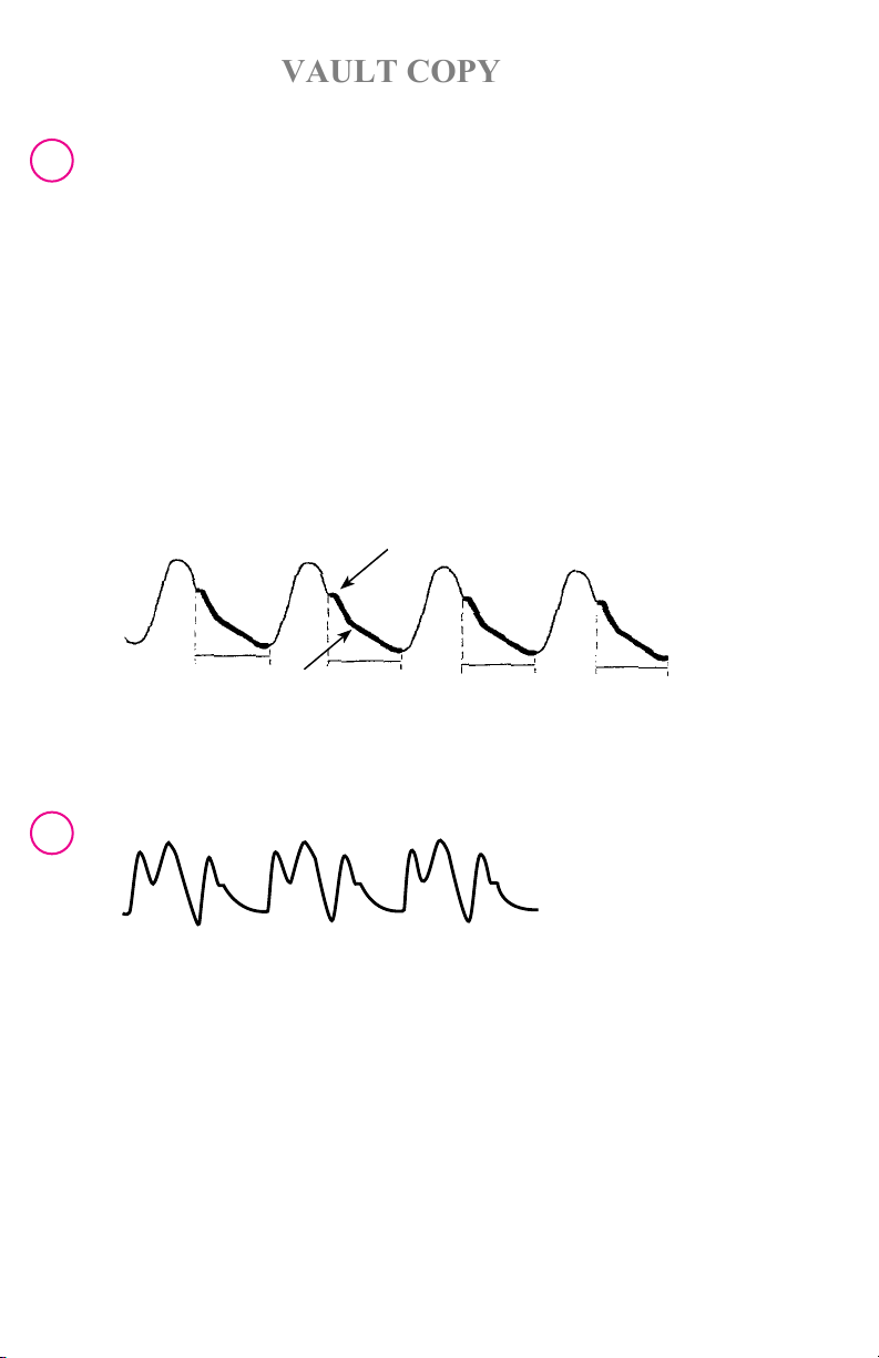
HIGHLIGHTED INFLATION MARKER
DICROTIC NOTCH
5 |
INFLATION MARKER
After initiating assist, the IAB INFLATION [only operational in the Semi Auto and
Manual Operation modes] and IAB DEFLATION controls can be adjusted to maximize
augmentation and hemodynamic unloading.
Timing at a frequency of 1:2 is illustrated below:
CLINICAL TROUBLESHOOTING – CLINICAL CONSIDERATIONS DURING
OPERATION
ECG:
There are several methods to correct conditions that alter or hamper the acquisition
of a reliable ECG. Reposition or replace ECG electrodes and check that the patient
cable is properly connected. In SEMI AUTO Operation mode, choose an alternate lead
selection or change ECG Gain setting.

| 6
VAULT COPY
| C S300™ | Abbre viate d O perat or’s G uid e |
Pressure:
Sensor IAB
The IAB Sensor Connector must be securely inserted into the IAB Sensor Module.
Always take care to avoid contaminating the tip of the Sensor Connector. Confirm
that the Sensor Connector is firmly seated in the IAB Sensor Module. If the Sensor
Connector is reconnected to the Sensor Module, the pump will automatically calibrate
the sensor within one minute or a calibration may be manually invoked
by pressing the Zero Pressure key while the pump is assisting.
Conventional IAB/Transducer
Flush arterial line at regular intervals per standard hospital procedure. Adequate flushing
to maintain pressure line patency and alignment of stopcock in the proper position will
prevent the majority of possible pressure trace problems.
Atrial Fibrillation:
In AUTO Operation mode, there are no special pump considerations for handling atrial
fibrillation. In SEMI AUTO Operation mode, use ECG Trigger. This will track random
rhythm most consistently, by automatically holding the IAB inflated until
the detection of the next R-Wave. Pressure triggering is NOT recommended in
atrial fibrillation.
Triggering on Ectopics:
The CS300 automatically deflates on and assists the ectopic beat, if the ectopic
R-wave is sensed. In SEMI AUTO Operation mode, if the ectopic beat is of small
amplitude, reliable triggering can be maximized if an ECG Lead is selected which
minimizes the amplitude difference between the normal QRS complex and that of the
ectopic beat. No special adjustments are necessary.
Cardiac Arrest – Ventricular Fibrillation:
When defibrillating the patient, the CS300 has protection and is completely isolated
from the patient and the defibrillator’s electrodes. However, the operator should stand
clear of the pump during defibrillation. This is particularly important when the CS300
is operated while disconnected from an earth grounding point, such as the A.C. power
receptacle.
Ventricular Standstill or Prolonged Cardiac Arrest:
If possible, use ECG or Arterial Pressure trigger during CPR. This facilitates
synchronization of the assist to the rate and rhythm of chest compressions. In AUTO
Operation mode, the ECG (R-wave) or Arterial Pressure signal will automatically be
selected as the Trigger Source. Choice is dependent upon relative signal quality. If
neither the ECG nor the Arterial Pressure signals produce adequate trigger reliability to
allow for AUTO Operation, the IABP may be triggered by its own internal clock. Select
the SEMI AUTO Operation mode and set the Trigger Source to Internal. The default
internal rate is 80 bpm but can be varied between 40 and 120 bpm by accessing the
Pump Options menu and setting the Internal Rate.

| Abbre viate d O perat or’s G uid e | C S30 0™ |
VAULT COPY
Prolonged Time in Standby and Thrombus on the IAB membrane:
If the CS300 is inadvertently placed in STANDBY, the time in STANDBY will appear on
the left side of the monitor screen. After 10 minutes an alert message will appear. The
audible alert is user selectable. Verify whether it is appropriate to resume assist. If so,
press the START key to resume assist.
WARNING: The patient balloon should not remain inactive (i.e., not inflating and defla-
ting) for more than 30 minutes due to the potential for thrombus formation.
USE IN ELECTRO-SURGICAL ENVIRONMENT
The CS300 IABP has built in Electro-Surgical Interference Suppression (ESIS) that
minimizes Electro-Surgical Unit (ESU) noise from disturbing system performance.
While the system will suppress ESU noise, it cannot eliminate it all together. Sparking
to tissue occurs when an ESU is operated. This generates noise that extends into the
ECG frequency range. Since the system must pass these frequencies, some ESU noise
may interfere with the ECG signal, particularly with high ESU power settings. Limiting
the power of this noise energy is desirable. The magnitude of interference is directly
related to the power setting of the ESU, which should be as low as possible for the
intended effect. Successful ECG triggering in the presence of ESU noise depends, to
a large extent, on proper patient preparation and ESU use. Following the guidelines
listed will minimize the amount of energy coupled from the ESU to the ECG input of
the CS300, generally resulting in stable ECG triggering. When the CS300 is in AUTO
Operation mode, it will automatically select Pressure Trigger when ESU interference
is detected and return to ECG a short interval after interference ceases. If the clinician
prefers to stay in Pressure Trigger during the operating room procedure, this can be
accomplished by selecting SEMI AUTO Operation mode. Then select Pressure Trigger
Source. Return to AUTO Operation mode when appropriate. When the CS300 is
used in an electrosurgical environment, the following techniques are recommended to
minimize interference from electrosurgical devices:
n Always use supplied MAQUET Operating Room ECG patient cable and lead wire
option. See “ECG Patient Cable Options” on page 10-7 of the CS300 Operating
Instructions for more information.
These cables are shielded and incorporate ESU suppression components
n Keep the ECG cables at right angles to the electrosurgical cables to the greatest
extent possible
n Locate the ECG electrodes as far away from the surgical site as possible
n Locate the ECG electrodes approximately equidistant from the surgical site to
minimize any difference in potential between electrodes
n Place all ECG electrodes on the same plane (either anterior or posterior) to minimize
any difference in potential between electrodes
n Place the electrosurgical return plate directly under the surgical site
n Use the minimum required electrosurgical setting
7 |
WARNING: External bedside monitors used with the CS300 in the operating room,
must be equipped with Electro-Surgical interference suppression.

| 8
VAULT COPY
| C S300™ | Abbre viate d O perat or’s G uid e |
CHANGE IN PRESSURE MONITORING SITE:
If patient’s pressure monitoring site is changed while assisting in SEMI AUTO or
Manual Operation mode, the INFLATION INTERVAL key can be quickly pressed and
released to recalculate arterial pressure transmission delay (APD). This will assure
accurate digital pressure display values and arterial pressure trace inflation interval
markers.
ALARMS AND ADVISORY MESSAGES
Help screens are provided to guide the user through set-up procedures and for
consultation regarding alarm message descriptions and alarm configurations. Help
screens are context sensitive and available based on the information displayed on the
screen. Detailed information on all Alarm and Advisory messages is provided in the
CS300 Operating Instructions. The IABP utilizes both auditory and visual alarm signals
to communicate the need for attention or awareness by the pump operator. ALARM
messages are displayed in the ALARM MESSAGES section of the monitor display.
HIGH PRIORITY ALARMS
High Priority Alarms indicate situations that require immediate Operator response.
Pumping is suspended for the majority of High Priority Alarms. A red flashing alarm icon
is displayed as seen above. The audio tone for a High Priority Alarm is a combination of
five notes a short pause, five notes a long pause and then this cycle repeats.
ALARM MESSAGE
[ALL OPERATION MODES]
Augmentation Below Limit Set
(Pumping is NOT suspended)
PROBABLE CAUSE
Diastolic Augmentation has dropped below
the user selected limit.
TRIGGER ALARMS
These alarms indicate the selected trigger source is either not available or not reliable.
Pumping is suspended and a steady tone sounds. Pumping will automatically resume
once the trigger has been reestablished.
ALARM MESSAGE
[AUTO OPERATION MODE]
Augmentation Below Limit Set
(Pumping is NOT suspended)
Poor Signals Persist Both ECG and Arterial Pressure signal quality
PROBABLE CAUSE
Diastolic Augmentation has dropped below
the user selected limit.
have been poor for a sustained period.

| Abbre viate d O perat or’s G uid e | C S30 0™ |
VAULT COPY
OPERATOR INTERVENTION
For No Trigger
n Reattach or reposition the electrode and check the integrity of all cable/lead
connections.
n Switch Operation to SEMI AUTO and increase the ECG Gain setting in the
PUMP OPTIONS menu.
n Use IAB Inflation and IAB Deflation controls to adjust timing and resume pumping by
pressing the START key.
n Verify that the transducer was not left vented; check all transducer cable
connections.
n Attempt to restore A.P. pulse height by flushing the circuit.
For Poor Signals Persist
n Attempt to restore A.P. pulse height by flushing the circuit, verify transducer
was not left vented; check integrity of all cable connections.
n Attempt to improve ECG signal by ensuring electrode contact and optimal
placement.
n If signal problem persists, switch Operation mode to SEMI AUTO. Verify
trigger source.
n Use IAB Inflation and IAB Deflation controls to adjust timing and resume pumping by
pressing the START key.
9 |
ALARM MESSAGE [SEMI AUTO OR
MANUAL OPERATION MODE]
No Trigger Valid trigger, as defined in Specification section,
No Pressure Trigger Valid trigger is unavailable or is lost while in
Check Pacer Timing The patient is not 100% paced or V/A-V pacer
Trigger Interference Electro-Surgical Noise [ESU] detected while the
ECG Detected
(Pumping is NOT suspended)
PROBABLE CAUSE
does not exist or is lost in ECG or Pacer Trigger
mode.
Pressure Trigger.
trigger interval varies >25% or an A-V pacer
rate is >125 bpm.
Pacer Trigger Source is selected.
ECG activity is detected persistently for 4-6
seconds while in the Internal Trigger mode.

| 10
VAULT COPY
| C S300™ | Abbre viate d O perat or’s G uid e |
OPERATOR INTERVENTION
For No Trigger
n Reattach or reposition the electrode and check the integrity of all cable/lead
connections.
n Try ECG lead selections via the ECG/AP Sources menu, or select EXT. ECG,
if appropriate.
n Adjust the ECG Gain by accessing the PUMP OPTIONS menu.
n Select a different trigger source using the TRIGGER SOURCE arrow keys. Resume
pumping by pressing the START key.
For No Pressure Trigger
n Verify that the desired Pressure Source, DIRECT/EXTERNAL, is selected. Use
the ECG/AP Sources menu to select the Pressure Source.
n Verify that the transducer was not left vented; check all transducer cable connections.
n If pressure trigger is required and manual threshold is selected, reduce the pressure
trigger threshold by using the PRESSURE THRESHOLD sub menu from the PUMP
OPTIONS menu.
n If appropriate, select a different trigger source using the TRIGGER SOURCE arrow
keys. Resume pumping by pressing the START key.
For Check Pacer timing:
n Select ECG trigger source, using the TRIGGER SOURCE arrow keys, when demand
pacing a patient.
n Reduce the Pacer rate.
n Adjust the A-V time interval to between 80 and 224 msec.
For Trigger Interference:
n Pumping automatically resumes when interference clears.
n If the condition persists, then select pressure trigger using the TRIGGER SOURCE
arrow keys.
n Verify timing and press the START key to resume pumping.
For ECG Detected
n Select ECG as the trigger source using the TRIGGER SOURCE arrow keys.
n Verify proper timing.
n Resume pumping by pressing the START key.

| Abbre viate d O perat or’s G uid e | C S30 0™ |
VAULT COPY
CATHETER ALARMS
The CS300 continually monitors specific parameters within the closed patient
pneumatic system. If a change is detected or a specific parameter is violated,
IABP Assist is suspended and the High Priority Alarm tone will sound.
n Status/Prompts apply to all Operation modes unless otherwise indicated:
A = Auto / SA = Semi Auto / M = Manual Operation mode.
ALARM MESSAGE PROBABLE CAUSE
Leak in IAB Circuit There is a small leak or gas gain in the IAB circuit, a
loose connection, or a high rate of helium diffusion.
Rapid Gas Loss A large leak has been detected in the IAB pneumatic
circuit.
IAB Disconnected The IAB catheter or extender tubing is disconnected.
Check IAB Catheter The IAB membrane is not completely unfolded, or the
IAB remains in the sheath immediately after insertion or
there is a kink in the IAB catheter or tubing.
Blood Detected Blood is detected in the IAB catheter.
Autofill Failure – No Helium The Helium tank is closed or empty.
Autofill Failure The IABP cannot fill the IAB catheter system
automatically.
Autofill Required
[SA / M]
The IAB fill mode has been changed from Manual to
AUTO without an autofill.
11 |
OPERATOR INTERVENTION
n Inspect the IAB and catheter extender tubing for any evidence of a leak, including the
safety disk/condensate removal assembly connections, IAB catheter connections,
autofill tubing and drain port. Check for blood in the tubing, if noticed, stop pumping
and notify a Physician.
n Verify all connections are leak free.
n For “Autofill Failure-No Helium” open or replace Helium tank if necessary.
n Inspect the IAB catheter and catheter extender for evidence of a kink or restriction to
Helium flow.
n Fill the IAB, if instructed, by pressing the IAB FILL key for 2 seconds. Resume
pumping by pressing START.
WARNING: If blood is observed within the catheter or catheter extender tubing at any
time during the IAB procedure, stop pumping, notify the physician immediately, and
prepare for IAB removal.
WARNING: When the System is operated in MANUAL FILL, the IAB gas loss and
catheter alarms are disabled. The message, “Gas Loss And Catheter Alarms Disabled”
will be displayed in the Advisory section of the display. The IAB status bar will not be
active.
WARNING: Under certain heart rate and timing conditions, catheter alarms may be
suspended. Refer to the Operating Instructions for further detail.

| 12
VAULT COPY
| C S300™ | Abbre viate d O perat or’s G uid e |
MEDIUM PRIORITY ALARMS
Medium Priority Alarms indicate situations in which a prompt Operator response is
required. This class of alarm does not suspend pumping, but may indicate a need for
corrective action. A yellow flashing alarm icon is displayed as seen above. The audio tone
for a Medium Priority Alarm is three notes, a pause, and then this cycle repeats.
n Status/Prompts apply to all Operation modes unless otherwise indicated:
A = Auto / SA = Semi Auto / M = Manual Operation mode.
ALARM MESSAGE PROBABLE CAUSE
Poor Signal Quality [A] Both ECG and Arterial Pressure signal quality
are poor while in ECG trigger.
No Pressure Source Available
[A]
IAB Optical Sensor Failure [ALL] There has been a failure of the Optical Sensor
Low Battery [ALL] Battery reserve falls below 30 minutes of
Neither a direct nor external blood pressure
source was detected.
in the IAB.
operating time.
OPERATOR INTERVENTION
For Poor Signal Quality
n Attempt to improve ECG signal by ensuring electrode contact and optimal placement.
Check integrity of all cable/lead connections.
n Attempt to improve Arterial Pressure by checking integrity of all cable connections. If
conventional transducer in use, verify the transducer was not
left vented and/or flush the lumen per standard hospital procedure.
For No Pressure Source Available
n If using a Sensor IAB, ensure that the sensor cable has been connected. Otherwise
provide an A.P. source by connecting a standard transducer or an interface cable
from the A.P. output of an external monitor to the pump.
For IAB Optical Sensor Failure
n Ensure that the sensor cable has been connected.
n Provide an alternate A.P. source by connecting a standard transducer or an interface
cable from the A.P. output of an external monitor to the pump.
For Low Battery
n Verify the Mains Power Switch, located above the AC power cord connector, is ON.
n Connect the system to an AC power outlet.
LOW PRIORITY ALARM
Low Priority Alarms are indications that Operator awareness is required. A yellow
flashing alarm icon is displayed as seen above. The audio tone for a low priority alarm
is two notes, a pause, and then this cycle repeats.
ALARM MESSAGE
[AUTO OPERATION MODE]
Unable to Update Timing Waveform quality is poor.
PROBABLE CAUSE

| Abbre viate d O perat or’s G uid e | C S30 0™ |
VAULT COPY
OPERATOR INTERVENTION
For Unable to Update Timing
n Check integrity of all cable connections. If transducer is in use, verify transducer was
not left vented.
n If pulse height is unusually low or over damped and transducer is in use, flush the
fluid lumen per standard hospital procedure.
n If not properly triggering or signal problems persist, switch OPERATION MODE to
SEMI AUTO. Verify trigger source and timing and resume pumping by pressing the
START key.
INFORMATIONAL MESSAGES
Informational Messages provide system information to the Operator. Informational
Messages display textual messages and, in some cases, are accompanied by an
infrequently repeating audio reminder tone.
n Status/Prompts apply to all Operation modes unless otherwise indicated:
A = Auto / SA = Semi Auto / M = Manual Operation mode.
MESSAGE PROBABLE CAUSE
IAB not filled [SA / M] System is in Manual Fill and user pressed the
START key when no fill had been performed.
Verify Proper Timing [SA / M] Operator has changed the trigger source.
Manual Fill IAB [SA / M] Notifies the operator when to manually fill the
IAB catheter with shuttle gas. Displayed in
the MANUAL FILL mode when the FILL key is
activated, venting the safety disk.
Leak Testing Safety Disk Indicates safety disk leak test is in progress.
Autofilling Indicates that the system is in the process of
Automatically purging and refilling the IAB with
Helium.
Automatic Operation mode is disabled
[SA / M]
Gas Loss and Catheter Alarms Disabled All leak and catheter alarms are disabled
Slow Gas Loss Alarm is Off Slow gas loss alarm has been disabled by
System is set to Manual Fill mode and the
operator tries to select AUTO Operation
mode.
when the manual fill mode is selected.
the user.
NOTE: Rapid gas loss function is still active.
13 |
Function Not Available Displayed when the operator presses an
Function unavailable in AUTO Operation
mode [A]
Battery in Use Indicates system is operating from an internal
unavailable key.
Displayed when the operator presses an
unavailable key while in the AUTO Operation
mode.
battery.

| 14
VAULT COPY
| C S300™ | Abbre viate d O perat or’s G uid e |
System Test OK All systems passed power-up diagnostics.
System Trainer Displayed when the System Trainer is being
used as ECG and Pressure source.
Auto R-Wave Deflate [A /SA] The patient’s rhythm is too random to predict
the occurrence of the next beat. In response,
the system has automatically selected the
R-Wave Deflation Mode.
R-Wave Deflate [A /SA] Operator has enabled R-Wave deflation by
moving the deflate key to the extreme right
position.
Irregular Pressure Trigger [SA] While Pressure is the Trigger source, erratic
trigger is due to:
1. Arrhythmic patient rhythm.
2. Late deflation; inhibiting pressure pulse
detection.
Manual Timing selected – See Help [M] The operator selected the Manual Operation
mode.
Verify Proper Timing [SA] The operator selected the Semi Auto
Operation mode.
Maintenance Required Code # ___ System maintenance may be required.
Low Helium Helium supply is below a preset reserve as
determined by tank pressure.
Prolonged Time in Standby Pump has been in STANDBY for at least 10
minutes.
A.P. Optical Sensing Module Failure There has been a failure of the A.P. Optical
Sensing Module in the pump console.
Unable to Calibrate IAB Optical Sensor A calibration is not completed for one or
more of the following reasons:
– the patient’s arterial pressure is too low
to reliably establish or update IAB Optical
Sensor Calibration
– there is a restriction in the catheter
– the IAB Fill Mode is set to Manual
IAB Optical Sensor Calibration Expired A calibration update has been intentionally
postponed for one or more of the following
reasons:
– the patient’s Mean Arterial Pressure may be
too low
– less than 15 minutes have elapsed since
last calibration
– pump is either in STANDBY or the IAB FILL
mode is set to MANUAL
| Abbre viate d O perat or’s G uid e | C S30 0™ |
VAULT COPY
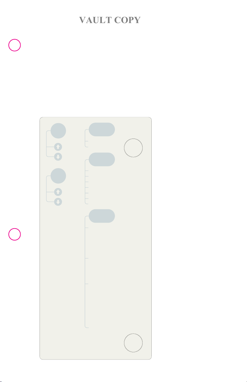
MENU GUIDE
The CS300 uses menus to provide rapid access to infrequently used functions.
The menu guide, below, is also located on the top of the CS300 console.
MENU NAVIGATION
The first step in the menu navigation is to open the desired menu by pressing the
associated key. The highlighted bar is always used as a pointer [cursor] to select menu
entries. The arrow keys in the menu navigation circle control the movement of the
highlighted bar. To select an alternative item, use the UP and DOWN arrow keys.
15 |
Ref.
Line
Aug.
Alarm
*Not available in "AUTO"
operation mode.
Menu Guide
24hr. Emergency Helpline
1.800.777.4222
ECG/AP
Sources
ECG Lead Source*
Pressure Source
Pump
Options
ECG Gain*
Pressure Threshold*
Internal Rate*
Slow Gas Alarm
IAB Fill Mode*
Arterial Pressure Delay*
R-Trac
User
Preferences
Display Preferences
Sweep Speed
Balloon Waveform
Brightness
ECG Inflation Markers
Audio Preferences
Alarm Volume
Standby Advisory Tone
Beep Volume
Printer Preferences
First Waveform
Second Waveform
Strip Length
Timed Print
Print on Alarm
Print Trigger & Alarm Log
Set Time and Date

| 16
VAULT COPY
| C S300™ | Abbre viate d O perat or’s G uid e |
PRINTER OPERATION
The dual trace recorder provides a hard copy record of patient waveforms. Printouts
follow the format defined by the setting in the Printer Preferences submenu, located
in the User Preferences menu. Dual or single trace formats may be selected.
Waveform choices are: ECG, Arterial Pressure and Balloon Pressure Waveforms.
At the completion of the recording, an annotated trailer is appended to the print. The
annotation describes patient and system status. The format of the annotation depends
upon the IAB Assist Frequency selection. When 1:2 or 1:3 is selected as the IAB
frequency, the recorder will print both assisted and unassisted systolic and diastolic
pressure information.
To initiate a printout, press the PRINT STRIP key. To start a continuous printout, hold
the PRINT STRIP key for two (2) seconds. The associated LED will blink as printing
continues. To stop the continuous printout, press the PRINT STRIP key again.
DOPPLER INFORMATION
The doppler used with the IABP uses ultrasound techniques to detect vascular blood
flow.
To Use the Doppler:
1. Open the right hand compartment on the storage bag. The doppler is located inside
this compartment.
2. Remove the doppler from the storage bag.
3. Press the button on the tether reel to retract the doppler.
4. If battery replacement is necessary, remove the cover of the battery compartment,
and lift out the old battery. Install a new 6LR61, 6LF22, or equivalent 9V alkaline
battery.
5. Replace cover.
6. Place a liberal amount of coupling gel on the transducer or on the patient’s skin.
7. Turn the unit on and position the probe over the artery to be examined.
8. Hold the probe at a 45° angle to the surface of the skin.
9. Adjust the position and angle of the probe to obtain the optimum audio signal.

| Abbre viate d O perat or’s G uid e | C S30 0™ |
VAULT COPY
SAFETY DISK LEAK TEST
This optional test measures the pneumatic leak rate(s) of the Safety Disk. The test
requires multiple interactions with the operator. Specifically during the course of the
test, the operator is requested to plug and unplug the outlet of the safety disk. The
IABP prompts the user at the appropriate times for this action.
WARNING: Safety Disk Leak Test MUST NOT be performed with the pump connected
to a patient’s IAB.
1. Press and hold the IAB Fill key while switching IABP ON/OFF to ON. Release the
IAB Fill key when the message LEAK TESTING SAFETY DISK appears in the
advisory section of the screen.
2. Using the supplied Luer plug, cap the IAB Catheter Extender Input when the
message PLUG DISK OUTLET appears on the display.
If the message UNPLUG DISK OUTLET appears, remove any connections that may
exist to the IAB Catheter Extender Input.
3. A double beep will sound at the end of the safety disk test. If the system passes
the test, the message SYSTEM TEST OK is displayed in the advisory section of the
screen.
Remove the Luer plug.
If IABP therapy is being started, then proceed to initial set up or return to the Power-
Up Procedure section on page 2-2 of the CS300 Operating Instructions to continue
the setup of the pump.
4. If the safety disk leak test fails, inspect all pneumatic connections and press the IAB
Fill key for two (2) seconds to repeat the test. If in doubt about the integrity of the
safety disk, replace it. See “Safety Disk/Condensate Removal Module” on page 7-7
of the CS300 Operating Instructions.
17 |

| 18
VAULT COPY
| 18
| C S300™ | Abbre viate d O perat or’s G uid e |
BATTERY OPERATION
The system automatically switches to battery power if AC power is not available
(intentionally or due to power loss). When AC power is restored, the system
automatically reverts from internal battery operation to AC Mains usage. The internal
battery pack charges while the system operates from AC Mains power.
Prior to portable operation, the battery should be fully charged. A fully charged battery
is indicated by a continuously illuminated battery-charging LED (located
on the front panel).
n Verify that the “Battery in Use” Informational Message and the Battery Indicator are
displayed when in battery operation.
n Battery charging is not active when the battery is in use.
n When the battery has approximately 30 minutes of operating time remaining,
the following occurs:
— The Medium Priority Alarm tone is activated.
— The “Low Battery” Medium Priority Alarm message is displayed on the screen
continuously.
— The Battery Indicator is displayed as empty and it starts flashing.
— The condensate removal module will not operate (to conserve remaining power).
Battery Charging
To charge the internal battery:
1. Leave the system power cord plugged in and set the MAINS On/Off to ON.
2. Check that the Battery Charging LED is illuminated (continuously or flashing
depending on state).
3. Allow a minimum of 8 hours to fully charge a low battery.
4. A fully charged new internal battery will provide at least 135 minutes of portable
operation.
NOTE: A reduction in run time will occur over a battery’s life due to age, storage tem-
perature and discharge depth. Batteries which are continually subjected to complete
discharge cycles without the recommended immediate recharging, can incur permanent
damage. See “User Maintenance” on page 7-10 of the CS300 Operating Instructions
for additional information.
OPERATION FROM DC-TO-AC INVERTER
The CS300 can be powered from a DC-to-AC inverter if the DC source and the inverter
meet the specifications defined in the CS300 “Operating Instructions” on page 5-4.
The DC source and inverter should be checked for proper operation by qualified
maintenance personnel prior to emergency use. The message Battery in Use will not
be displayed during proper AC inverter Operation.

| Abbre viate d O perat or’s G uid e | C S30 0™ |
VAULT COPY
TRANSPORT CONSIDERATIONS
Portable Operation
MAQUET recommends the following:
1. Battery fully charged prior to starting transport.
2. Back up battery pack available.
3. Altitude changes are compensated for automatically in the Auto Fill mode or
manually in the Manual Fill mode.
4. The system must be properly secured when used in an ambulance, helicopter,
or fixed wing aircraft.
The Universal Transport System (UTS) is specifically designed for air and vehicular
transport. The UTS version mechanically attaches to a docking station for high strength
mounting. Refer to additional detail on the UTS on page 5-9 of the CS300 Operating
Instructions.
WARNING: The user should continually rely on visual alarm messages during high
noise transport situations.
CAUTION: Prior to transport, ensure that the Helium cylinder yoke handle is tight and
the Helium pressure gauge is a least 25% full. Approximately every 30 minutes during
transport verify that the yoke handle is tight and that a noticeable pressure drop has
not occurred.
19 |
NOTE: Prior to using the system in any other position except vertical, consult with
Technical Service.
NOTE: For information on outfitting an aircraft for IABP transport contact your
local MAQUET sales representative. See “Accessories” on page 10-8 of the CS300
Operating Instructions for information on the Transport Docking Station.
EFFECTS OF ALTITUDE CHANGES DURING AIR TRANSPORTATION
NOTE: Before using the system in air transportation, check for sufficient supply of
Helium since the balloon will be filled several times.
For proper Operation during air transport, the IABP balloon pressure must adapt to
local atmospheric pressure. In the Auto Fill mode the system will automatically purge
and fill the IAB when local atmospheric pressure decreases or increases by 25 or 50
mmHg, respectively. These pressure changes occur approximately every 1,000 feet of
rise or 2,000 feet of drop in altitude.
WARNING: The Auto Fill mode should be used during air transport. If the Auto Fill
mode cannot be used and the Manual Fill mode is required, ensure that a manual fill is
performed at each interval and altitude that an Auto Fill would occur.
| 20
VAULT COPY
| C S300™ | Abbre viate d O perat or’s G uid e |
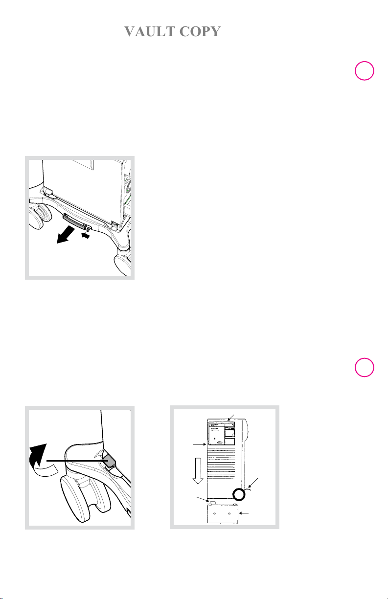
REMOVING PUMP CONSOLE FROM THE CART
The console can be removed from the cart with or without the battery pack attached.
When removing the pump console or the monitor from the cart or returning them to the
cart, ensure that the wheels of the cart are in the locked position.
To remove the console with the battery pack attached:
Unlock the console by pressing the tab to the right of the console release handle and
pull the handle straight out (fig. 1). Lift the pump console straight up and off the cart.
Fig. 1
To remove the console by detaching the battery pack:
With the console on the cart, lift the battery release levers to the unlock position (fig. 2).
Lift the console straight up and off the cart. To release the battery from the cart, unlock
the battery pack by pressing the tab to the right of the console release handle and pull
the release handle straight out. Lift the battery pack off the cart. With the release levers
in the unlocked position, lift the pump console and lower it straight down onto the
battery pack. Return the release levers to the locked position (fig. 3).
Lift from here
Pump
Console
Release
Levers
Connector
Block from
this view,
it is in the
back left corner
Battery Pack
Fig. 2 Fig. 3

| Abbre viate d O perat or’s G uid e | C S30 0™ |
VAULT COPY
To attach the monitor to the pump console:
Detach the monitor from the cart handle by pressing the button on the rear of the
monitor (fig. 4). Attach the monitor to the top of the pump console. Make sure the
monitor is securely attached before moving the system. Extend the console handle until
it locks into position, tilt the System, and pull to transport (fig. 5).
21 |
Release button
Fig. 4 Fig. 5
PULL

Subject
VAULT COPY
·
Cardiovascular LLC or its affiliates
· Copyright 2009 MAQUET
PN: 0070-00-1126 D
·
MCV-BA-81000101-EN-01
Datascope Corp.
Cardiac Assist Division
15 Law Drive
Fairfield, NJ 07004
Phone: +1 973 244 6100
For local contact:
Please visit our Website
www.datascope.com
www.maquet.com
® MAQUET Registered Trademark of MAQUET GmbH & Co. KG · Reg. QUG:
Caution: U.S. Federal Law restricts this device to sale by or on the order of a physician. Refer to Instructions for Use for current indications, warnings,
contraindications, and precautions.
to modifications due to technical development
 Loading...