

Maquet Servo Ventilator 900 D, Servo Ventilator 900 E, SERVO VENTILATOR 900 C Service Manual
Page 1
SERVO VENTILATOR 900 C/D/E
Service Manual
Page 2

2
Contents
Introduction . . . . . . . . . . . . . . . . . . 4
Principle diagram. . . . . . . . . . . . . . . . 6
Pneumatic unit
Gas flow through the ventilator . . . . . . . . . 8
Gas supply . . . . . . . . . . . . . . . . . 9
Bellows and spring assembly. . . . . . . . . . 10
Gas supply unit . . . . . . . . . . . . . . . 11
O
2
cell . . . . . . . . . . . . . . . . . . . 12
Relief/safety valve and working
pressure manometer . . . . . . . . . . . . . 12
Flow transducer . . . . . . . . .
. . . . . . 14
Pressure transducer . . . . . . . . . . . . . 15
Inspiratory valve and step motor . . . . . . . . 16
Expiratory valve and pull magnet . . . . . . . . 17
Non-return valve . . . . . . . . . . . . . . . 17
Transducer interface . . . . . . . . . . . . . . 18
Electronic unit
Principle of operation . . . . . . . . . . . . . 19
Reference level generation . . . . . . .
. . . . 20
Regulation of inspiration. . . . . . . . . . . . 23
Timing . . . . . . . . . . . . . . . . . . . 28
Monitoring . . . . . . . . . . . . . . . . . 33
Regulation of expiration . . . . . . . . . . . . 39
Voltage supply . . . . . . . . . . . . . . . 41
Input/output . . . . . . . . . . . . . . . . 42
Disassembling
Disassembling the pneumatic unit . . . . . . . . 44
Disassembling the electronic unit. . . . . . . . . 44
Replacement of step motor assembly
and pull magnet . . . . . . . . . . . . . . . 45
Replacem
ent o
f power supply unit . . . . . . . 45
Replacement of safety catches . . . . . . . . . 45
Replacement of flow transducer . . . . . . . . 46
Adjustments
Adjustment of meters Z1 and Z2 . . . . . . . . 46
Adjustment of valve arm. . . . . . . . . . . . 46
Replacement and adjustment of R5 . . . . . . . 47
Removing the front panel knobs . . . . . . . . 47
Front panel potentiometer adjustments. . . . . .
48
Troubleshooting . . . . . . . . . . . . . . . . 49
Index . . . . . . . . . . . . . . . . . . . . 52
Block diagram . . . . . . . . . . . . . . . . . 56
Contents
To the responsible service personnel
The contents of this document are not binding.
If any significant difference is found between
the product and this document, please contact
MAQUET for further information.
We reserve the right to modify products without
amending this document or advising the user.
We recommend using MAQUET authorized
personnel for all service and repairs and the
use of MAQUET exchange parts or genuine
spare parts. MAQUET will not otherwise assume
responsibility for the materials used, the work
performed or any possible consequences of
same.
The Servo Ventilator 900 was orginally
manufactured and sold by Siemens. Responsibility
for the product was assumed by MAQUET Critical
Care in 2003. Manufacturing of the product was
discontinued in 2004.
Please note that this Service Manual has only
been re-labeled from Siemens to MAQUET. No
further significant changes are made. Thus,
some information in the Service Manual may be
outdated.
In case of questions, please contact your local
MAQUET representative
Your local MAQUET representative supplies factory
calibrated and tested plug-in circuit boards as well
as other spare parts indicated in the spare parts
list. When exchanging spare parts, always state
serial number of the apparatus and fault-symptom.
Note that the Operating Manual is an indispensable complement to the Service Manual for
proper servicing.
About this manual
This Service Manual is intended for Servo Ventilator 900 C,
D and E. When reading the manual, please note:
SV 900 C SV 900 D SV 900 E
Read all
information
Do not read
information out-
lined in red
Do not read
information in
shaded areas
Page 3

3
Product information program
This Service Manual is a part of a comprehensive information program for Servo Ventilator 900 C/D/E.
The program is planned to contain the following:
Promotional and Scientific Publications
Operating and Service Instructions
Product Training Material
Brochure Servo Ventilator
Concept
Application
Brochures:
Intensive Care,
Anesthesia,
Transportation
Operating
Manual
Brief Operating
Instructions
Training
Instructions
Front Panel
Flip-chart
Advisory
Booklet for
Instructors
Panel Block
Wall Diagram
for Cleaning
Slide Series
including
Textbook
Trainee’s Set
Product Leaflet
“I am breathing
through a
ventilator”
Film and
Booklet
Video
programs,
Video guide,
Video news
Reprints
Circuit Diagram
The Patient’s
ABSee@
Cards and
Poster
Service Manual
Page 4
4
Introduction
Principle of operation
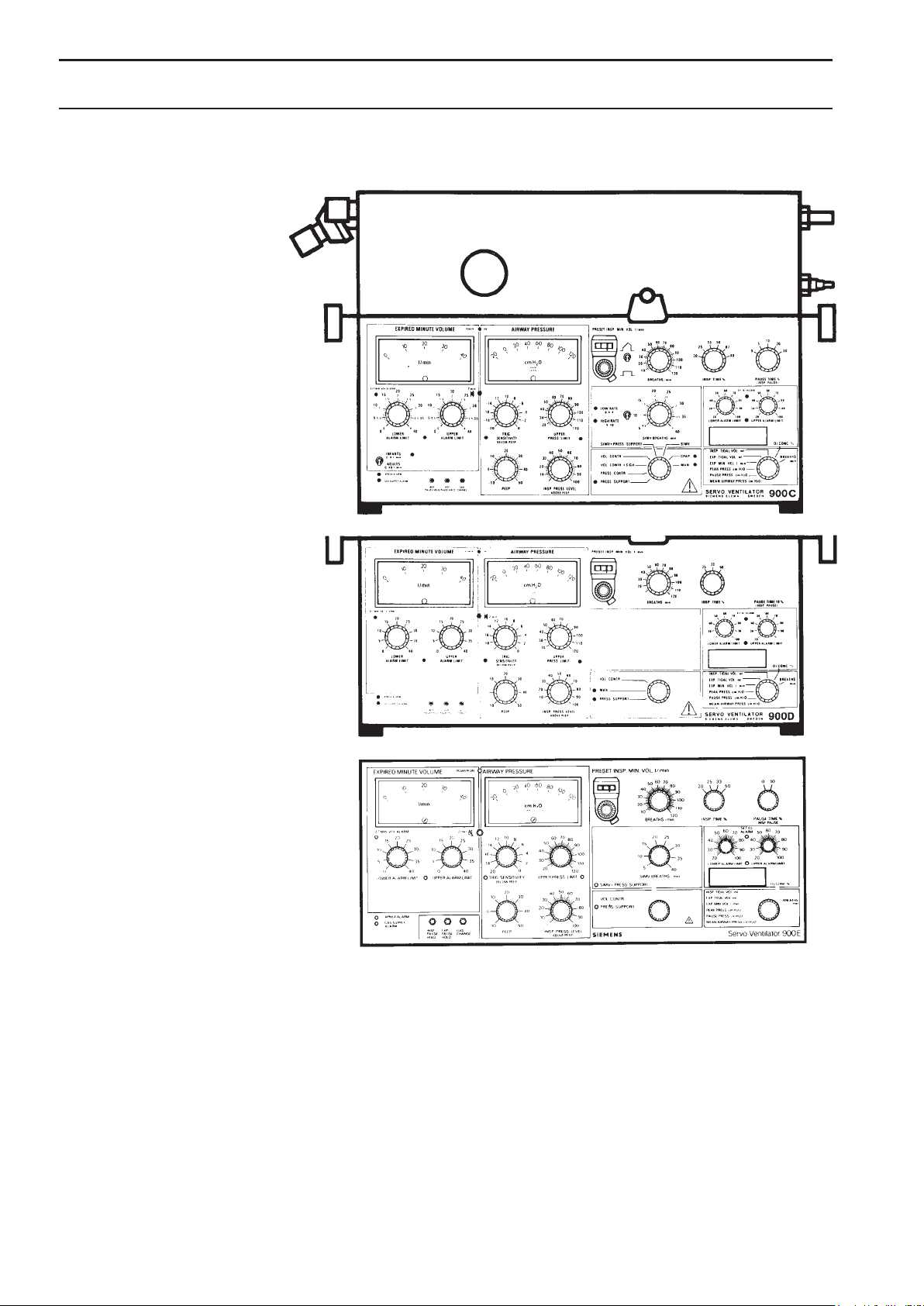
The Servo Ventilator 900 C/D/E consists of two separate units.
The pneumatic unit comprises the gas conduction
system with two pressure transducers, two flow
transducers and two servo valves.
Each transducer, continuously delivers its actual value
to the electronic unit.
The servo valves are used as CONTROLLING
ELE MENTS for the control of inspiratory and expiratory
gas conduction.
The electronic unit comprises three controlling
systems, two for regulation of inspiration and one for
regulation of expiration.
The three controlling systems will be in use, one at a
time, depending on the TIMING control and the se lected
ventilation MODE.
Pneumatic unit
Electronic unit SV 900 C
Electronic unit SV 900 D
Electronic unit SV 900 E
Page 5
5
Introduction
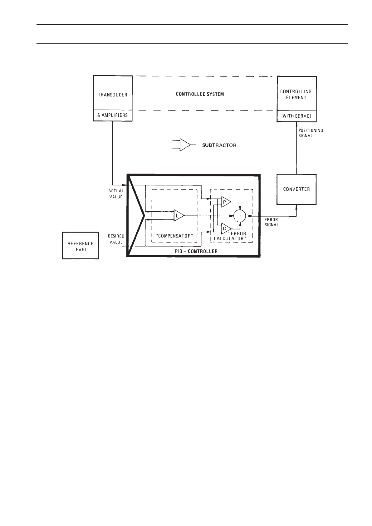
Feedback control
(= regulation system)
Each of the controlling systems comprises its PID controller, (P=Proportional action, I=Integral action and
D=Derivative action), as shown in the picture.
The CONTROLLING ELEMENT will be positioned by
the PID-CONTROLLER (output).
P-action gives a continuous basic positioning.
(Thereby the ACTUAL VALUE will correspond to the
DESIRED VALUE).
I-action gives a slowly varying positioning compensation for small long time error (in the ACTUAL
VALUE ).
D-action gives a speed-up positioning reaction at fast
changes (in the ACTUAL VALUE).
The actual value from the TRANSDUCER in use is
compared with the desired value from REFERENCE
LEVEL. The difference between the ACTUAL VALUE
and the DESIRED VALUE results in an ERROR SIGNAL,
which is converted to a positioning signal for the
CONTROLLING ELEMENT (inspiratory and expiratory
valve respectively). The valve in use will then be moved
into such a position that the error will be cor rected. In this
way, the desired value is maintained independently of
changes in the airways and the lungs.
Page 6

6
!
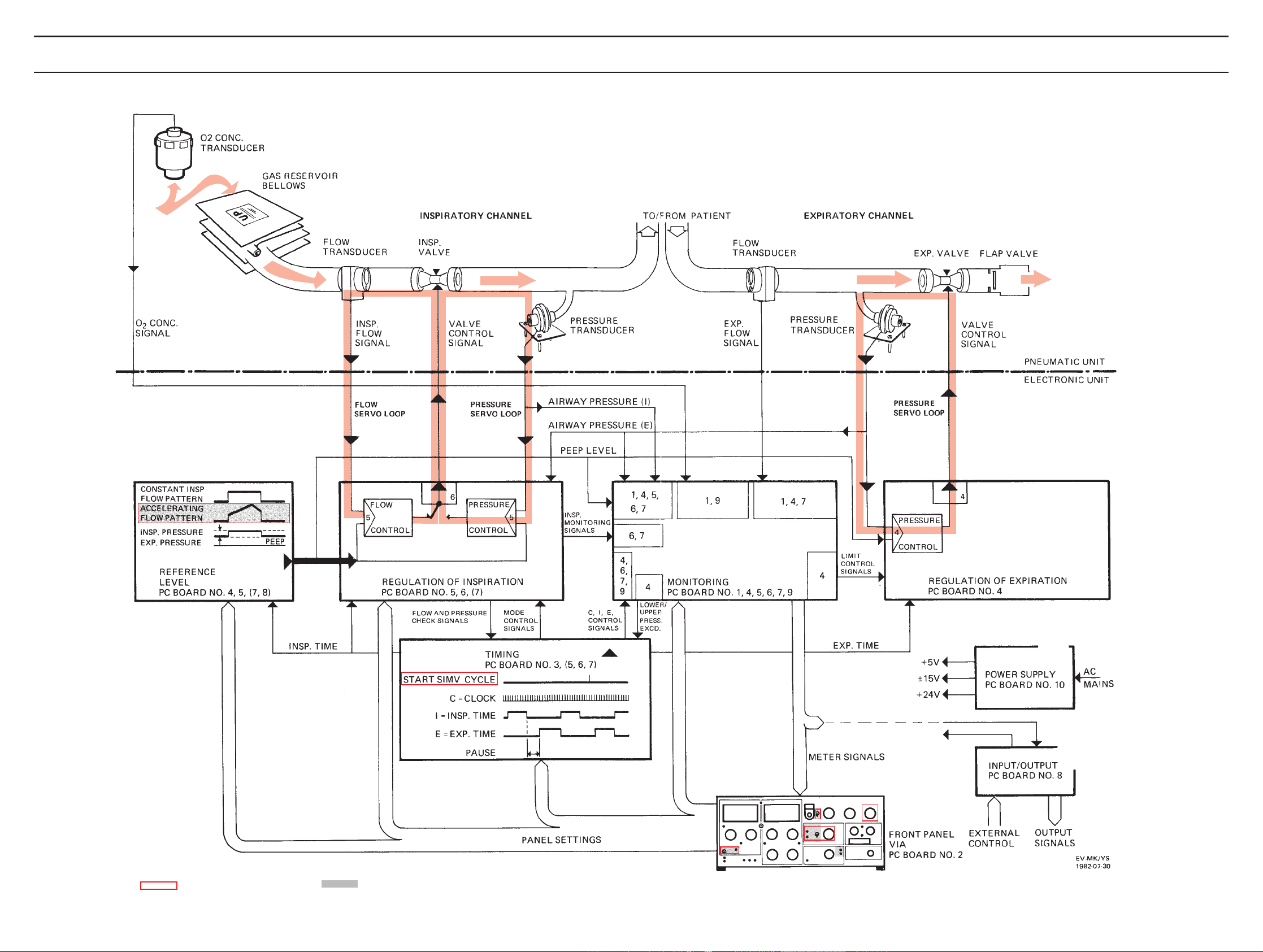
Reference level
The main block REFERENCE LEVEL generates the
DESIRED VALUE for each regulating system, corresponding to the settings on the front panel.
@
Regulation of inspiration
The regulation of inspiration is done by means of the FLOW
SERVO LOOP in the following modes: VOL. CONTR. VOL.
CONTR. + SIGH. MAN., each mandatory inspiration during
SIMV + PRESS. SUPPORT and each mandatory inspiration
during SIMV.
The actual value for the controller in this loop comes
from the FLOW TRANSDUCER in the inspiratory channel.
The regulation of inspiration is done by means of the
PRESSURE SERVO LOOP in the following modes: PRESS
SUPPORT. PRESS. CONTR., CPAP, each spontaneous
inspiration during SIMV + PRESS.SUPPORT and each
spontaneous inspiration during SIMV.
The actual value for the controller in this loop comes
from the PRESSURE TRANSDUCER in the inspiratory
channel.
The ERROR SIGNAL from the controller in use (flow
or pressure), is fed to a converter, common to both
inspiratory servo loops, which delivers the valve
control signal to the inspiratory valve (positioning).
For both servo loops, the inspiratory valve is the
controlling element in regulation of inspiration.
#
Timing
Reference timing pulses (START SIMV CYCLE, CLOCK,
INSP.TIME and EXP.TIME) are generated in this main block.
The TIMING gets some command variables from the
front panel settings.
$
Monitoring
The monitoring of all values that are displayed on the panel
meters and the digital display takes place in this main
block.
Some of the readings are compared with preset alarm
limits and visual and audible alarms are acti vated if the
preset limits are exceeded.
The monitoring system is independent of the
regulating systems.
The pressure limiting system is included in this
main block.
%
Regulation of expiration
The regulation of expiration is done by means of the
PRESSURE SERVO LOOP during expiration in all modes
when using PEEP.
The actual value for the controller in this loop comes
from the PRESSURE TRANSDUCER in the expiratory
channel.
The error signal from the controller is fed to a converter which delivers the valve control signals for the
expiratory valve (positioning).
The expiratory valve is the controlling element in
regulation of expiration.
^
Power supply
The four regulated supply voltages are; +5V, ±15V and
+24V.
&
Input/output
Output signals are buffered in this main block.
Some of the functions of the ventilator can be
externally controlled via inputs in this block.
= Not valid for SV 900 D = Not valid for SV 900 E
Principle diagram
Page 7
7
Principle diagram
= Not valid for SV 900 E
= Not valid for SV 900 D
!
@
#
$
%
^
&
Page 8
8
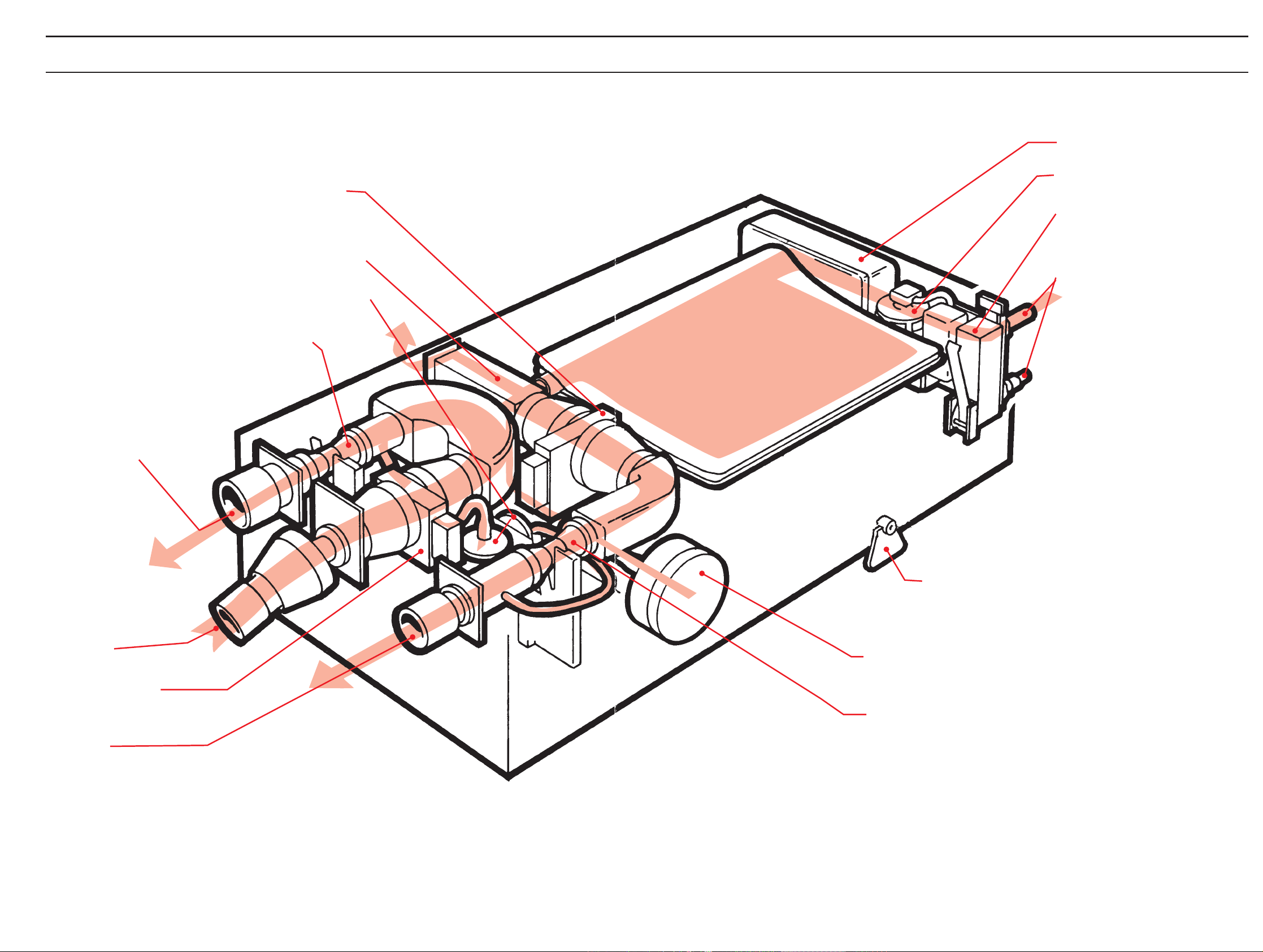
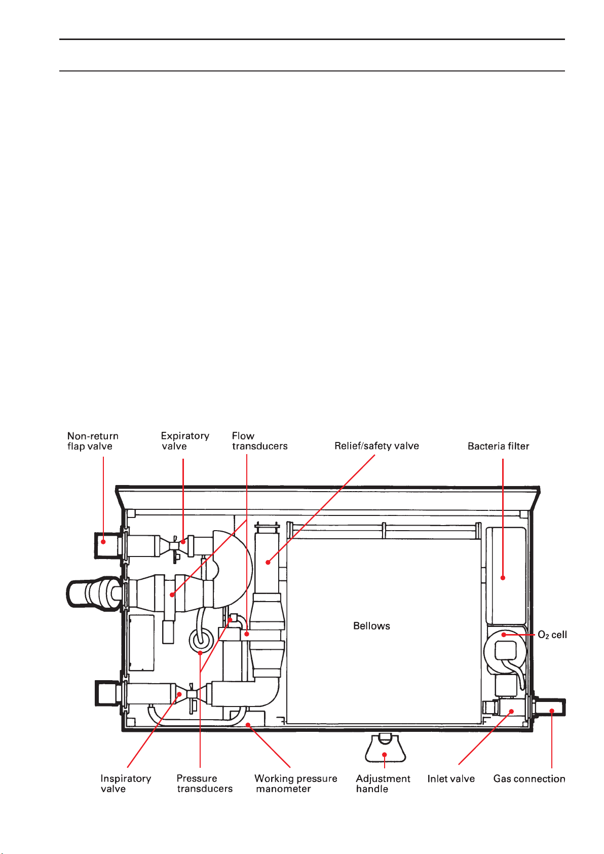
Pneumatic unit
The flap valve prevents
back flow of gases in
the expiratory tubing.
It is essential for the
trig function
The working pressure is
mechanically adjusted
Gas flow through the ventilator
The gas flow to the patient
is measured
The safety valve opens if the
bellows is overfilled or if the
pressure in the bellows exceeds
approximately 120 cm H
2
O
The airway pressure is measured
The gas conduction from the
patient is regulated
From patient
The gas flow from the
patient is measured
To patient
The gas is filtered
O
2
concentration in the gas is
measured
The gas supply is regulated so
that a constant filling volume is
maintained in the bellows
Gas inlets
A more detailed description of the pneumatic
unit is found in the Training Instructions
The working pressure is shown
on a manometer
The gas conduction to the patient
is regulated
Page 9
9
Gas supply
The lower gas inlet is used for high pressure gases 250700 kPa). The inlet can be connected either via a gas mixer
or directly to the hospital central gas supply, to gas bottles
or to a compressor.
The upper gas inlet is used for low pressure gases,
e.g. from an anesthesia circuit or a flowmeter. Nor mally,
only one of the two inlets is used at a time.
In any case, the gases pass a one-way valve, an
O
2
cell and a bacteria filter. The bacteria filter remo ves
99.998% of all particles down to a size of 0.3 mic rons.
When an anesthesia vaporizer is used, the gas supply
unit has a different construction with three nipples. For
further information, see the Operating Manual for the
vaporizers.
When the gas is supplied via the high pressure inlet,
a constant filling volume is obtained in the bellows by
means of the gas inlet regulator y function of a controlled
inlet valve. A constant working pressure is obtained by
the action of the spring as sembly.
Pneumatic unit
Page 10
10
Pneumatic unit
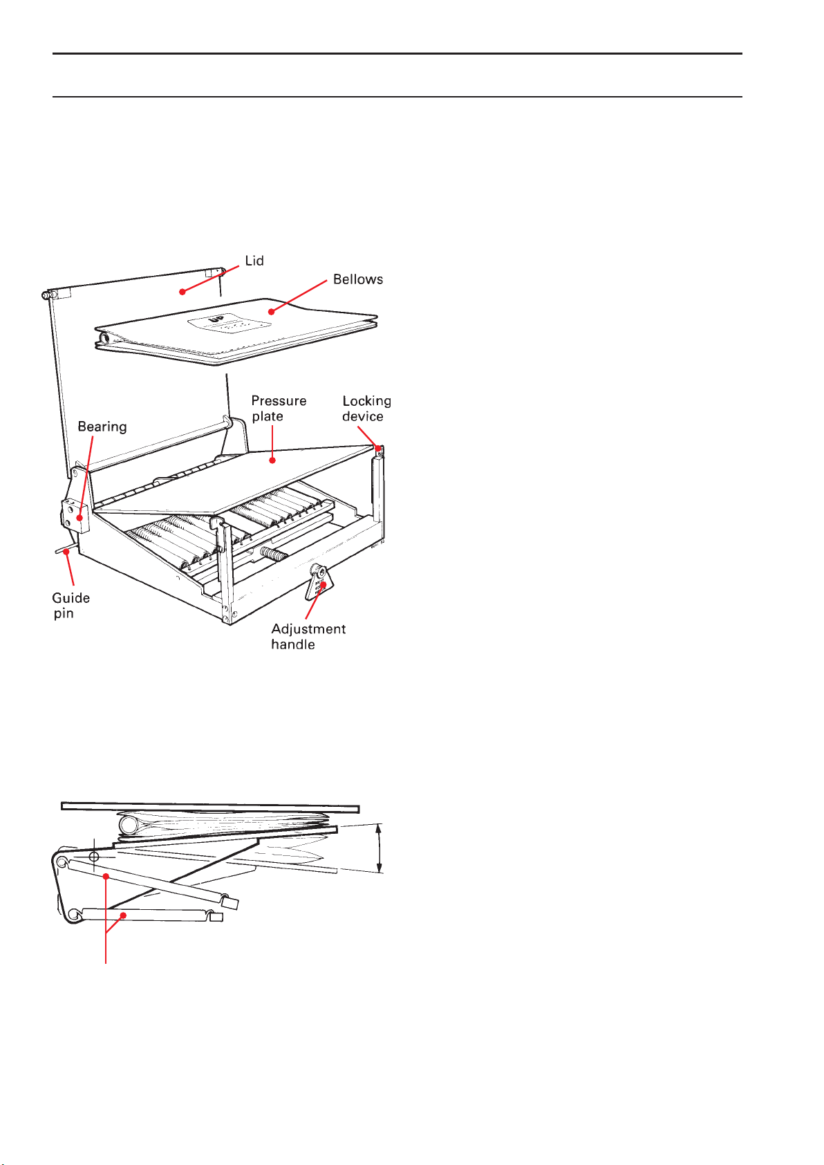
Bellows and spring assembly
The bellows are placed in a double coil spring set between
two metal plates. The lower plate is movable and spring
tensioned. The upper plate acts as a lid, which is firmly
positioned above the bellows.
A double coil spring set is arranged to give a constant
pressure to the bellows, independent of the plate position.
The pressure is set by the adjustment hand le PRESET
WORKING PRESSURE.
Coil springs
Page 11
11
Pneumatic unit
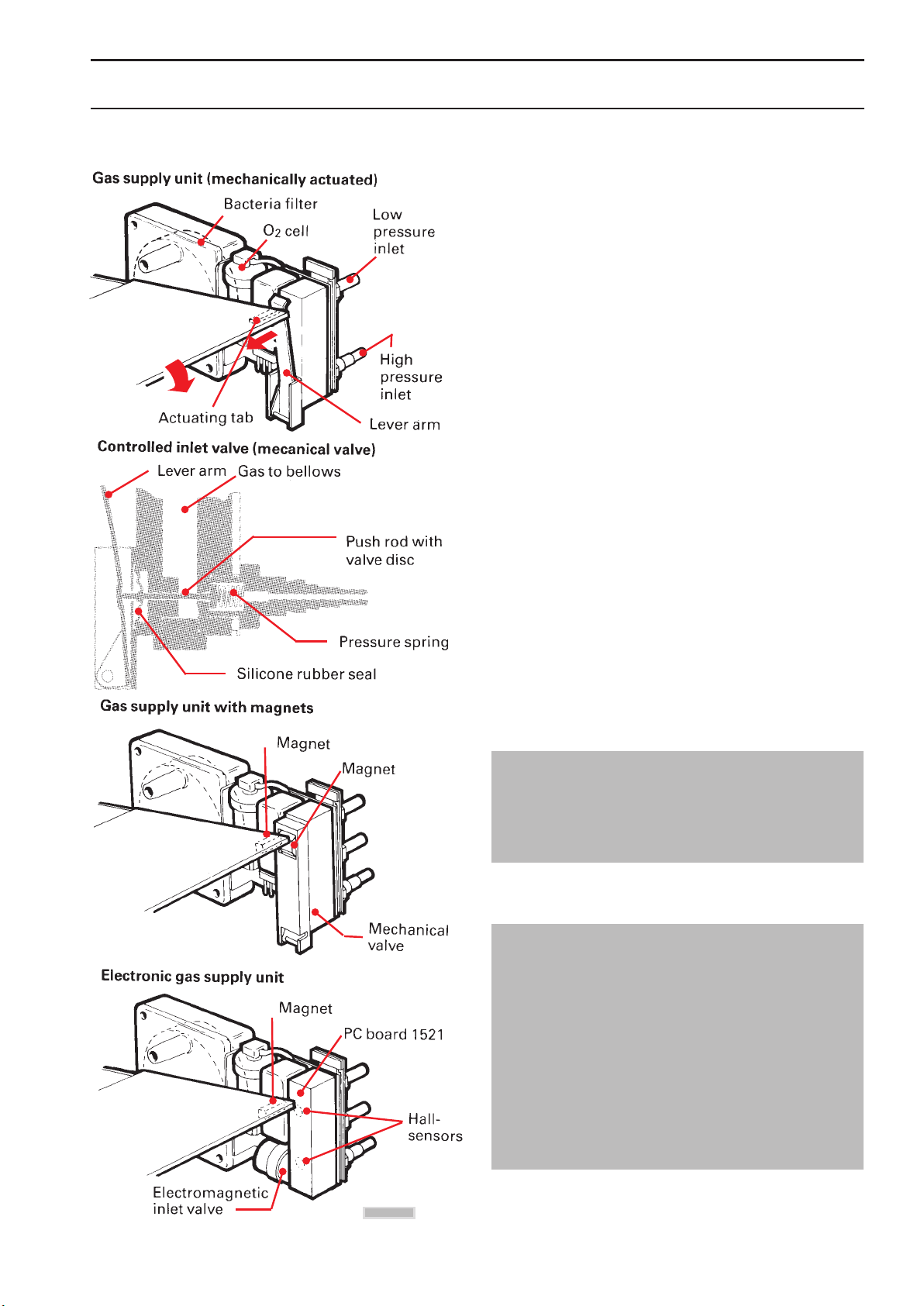
Gas supply unit
The gas supply unit contains an on-demand valve for the
high pressure gas, a controlled inlet valve, two one-way
valves, the O
2
cell holder and a bacteria fil ter.
Normally, the high pressure inlet is used and the
bellows are filled through the controlled inlet valve, a oneway valve and the bacteria filter.
Mechanically actuated gas supply unit
The pressure plate acts upon the controlled inlet valve
via the lever arm. Before connecting the gas supply, the
bellows are empty, the pressure plate in top position and
the controlled inlet valve open. When connecting high
pressure gas, the bellows fills, the actuating tab on the
right edge of the pressure plate goes down against the
lever arm until the con trolled inlet valve has closed. The
pressure plate is then in its regulating position, which
means that during inspiration, gas is continuously fed to
the bellows. Thus a constant gas volume is kept in the
bellows when using the high pressure inlet.
When a constant gas flow (from a flowmeter) is
supplied via the low pressure inlet, excess gas will be let
out from the bellows by the relief valve (surplus function).
Gas supply unit for Vaporizer with magnets
When using Vaporizer 950, 951 or 952, a gas supply
unit with three gas inlets has to be used and the
actuating tab on the pressure plate must be replace by
a magnet kit.
Electronic gas supply unit for vaporizer
The gas is normally supplied via a gas mixer at the
lower gas inlet. This inlet is controlled by a 24 V
electromagnetic inlet valve.
The built-in PC-board has two Hall-sensors,
sensing the position of the pressure plate magnet.
When the magnet reaches up to the upper Hallsensor, the inlet valve will open. When the magnet
reaches down to the lower Hall-sensor, the inlet valve
will close.
Also when there is no power, the inlet valve is kept
closed.
= Not valid for SV 900 E
Page 12
12
Pneumatic unit
O2cell
The O2 cell used in the ventilator gives an output vol tage
proportional to the partial pressure of O
2
at the cell. At
constant sum of barometric pressure and WORKING
PRESSURE (and constant temperature), the output voltage
is proportional to the relative O
2
CON CENTRATION.
For each O
2
cell, the variable output will stay at
a fairly constant level during the life time of the cell
(approximately 800 000 %xhours).
The output voltage level from the cell is usually within
7-15 mV in normal air.
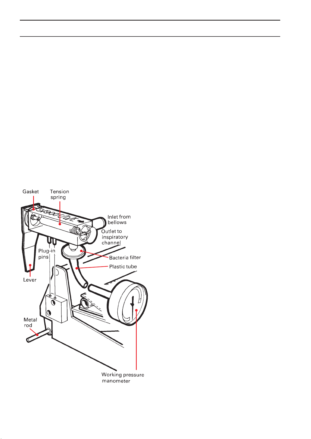
Relief/safety valve and working pressure manometer
The working pressure manometer is connected to the
safety valve via a plastic tube. A bacteria filter pro tects the
manometer from contamination.
Page 13
13
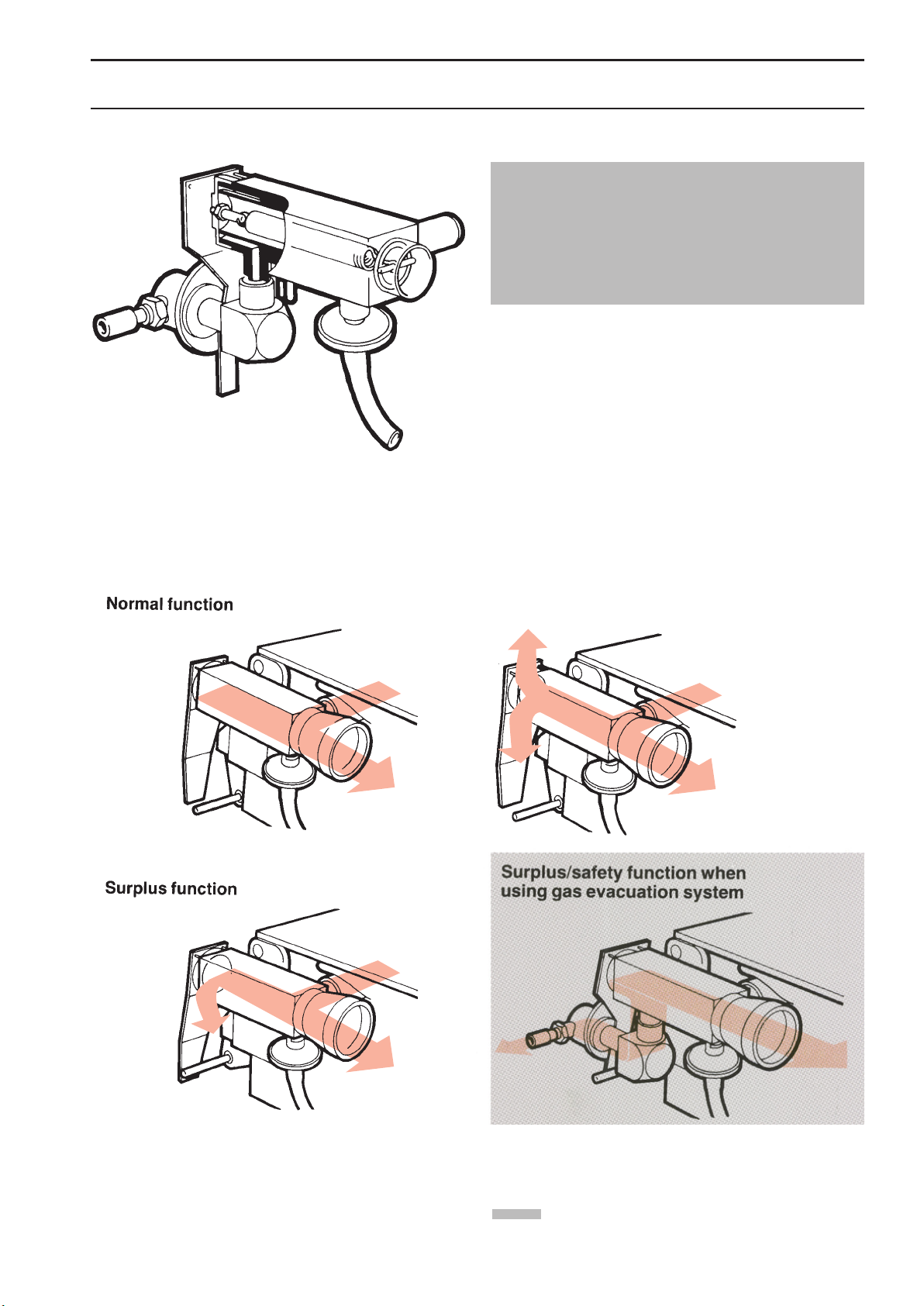
Safety function
Pneumatic unit
Relief/safety valve for gas evacuation
A special reief/safety valve has to be used for gas
evacuation.
For detalíls, see corresponding Operating Manual.
The relief/safety valve may be opened in two ways. Firstly,
if the bellows tend to overfill, a metal rod will push the lever
to let out excess volume (surplus func tion). Secondly, if the
working pressure exceeds approximately 120 cm H
2
O, the
valve will let out excess pressure (safety function).
= Not valid for SV 900 E
Page 14
14
Pneumatic unit
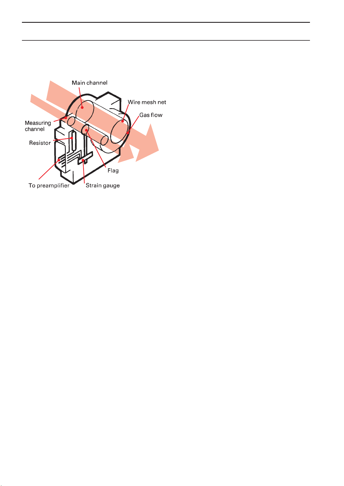
Flow transducer
The inspiratory and expiratory flow transducers have
the same construction. The gas flows through the flow
transducer in two parallel channels, one large main
channel, and one small measuring channel.
The main channel is fitted with a wire mesh net, the
resistance of which causes a certain proportion of the
gas to flow through the measuring channel.
The flow through, and the differential pressure
across, the measuring channel acts on a small metal
disc (“flag”), which, via a metal pin presses on a small
semiconductor strain gauge. This consists of diffused
resistors on both sides of an elastic silicone rod. The
resistors are connected as a part of a Wheatstone bridge,
the other part of which is situ ated on the TRANSDUCER
INTERFACE board (PC 765).
The more flow in the channel, the higher the pressure on the strain gauge. The change in resistance in
the Wheatstone bridge, is converted to a correspond ing
signal voltage.
The output signal from the flow preamplifier is a nonlinear function of the flow. The flow preamplifier signals
are linearized on PC board 5 (inspiration) and on PC
board 4 (expiration), respectively.
A resistor, 220 Ohms, 6W, is moulded into the
transducer and is used for heating of the expiratory flow
transducer. The transducer is heated to approxi mately
60°C (140°F) to prevent condensation of water vapour.
The inspiratory flow transducer has the same resistor,
but since it is not connected to any voltage, it will not be
heated.
If water should condense in the expiratory flow
transducer, the resistance of the wire mesh net in creases.
Thus the output signal will increase. This can be seen on
the meter EXPIRED MINUTE VOLUME, or on the digital
display, as an increased reading. The accumulation of
medicaments, mucus and secretions in the expiratory
flow transducer gives the same result.
For details on cleaning and calibration of the flow
transducer, see the chapters Routine cleaning and
Calibration in the Operating Manual.
Page 15
15
Pneumatic unit
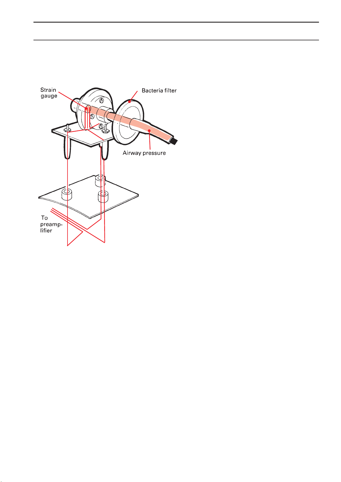
Pressure transducer
The pressure transducers in the inspiratory and expi ratory
channels are of the same type.
The gas pressure acts upon a silicone rubber membrane into which is moulded a strain gauge of the
same type as in the flow transducers. The strain gauge
resistors are connected as a part of a Wheat stone bridge,
the other part of which is situated on the TRANSDUCER
INTERFACE board (PC 765).
The output signal voltage from the pressure amplifier
is proportional to the gas pressure.
When replacing the pressure transducers, the
preamplifier zero and gain have to be adjusted. For
details, see the chapter Calibration in the Operating
Manual.
Each pressure transducer is connected to its chan nel
via a plastic tube and a bacteria filter. The bac teria filter
and the plastic tube for the inspiratory channel should be
replaced after every 1000 hours of operation.
The bacteria filter and the plastic tube for the expiratory channel should be replaced after ever y patient.
Page 16
16
Pneumatic unit
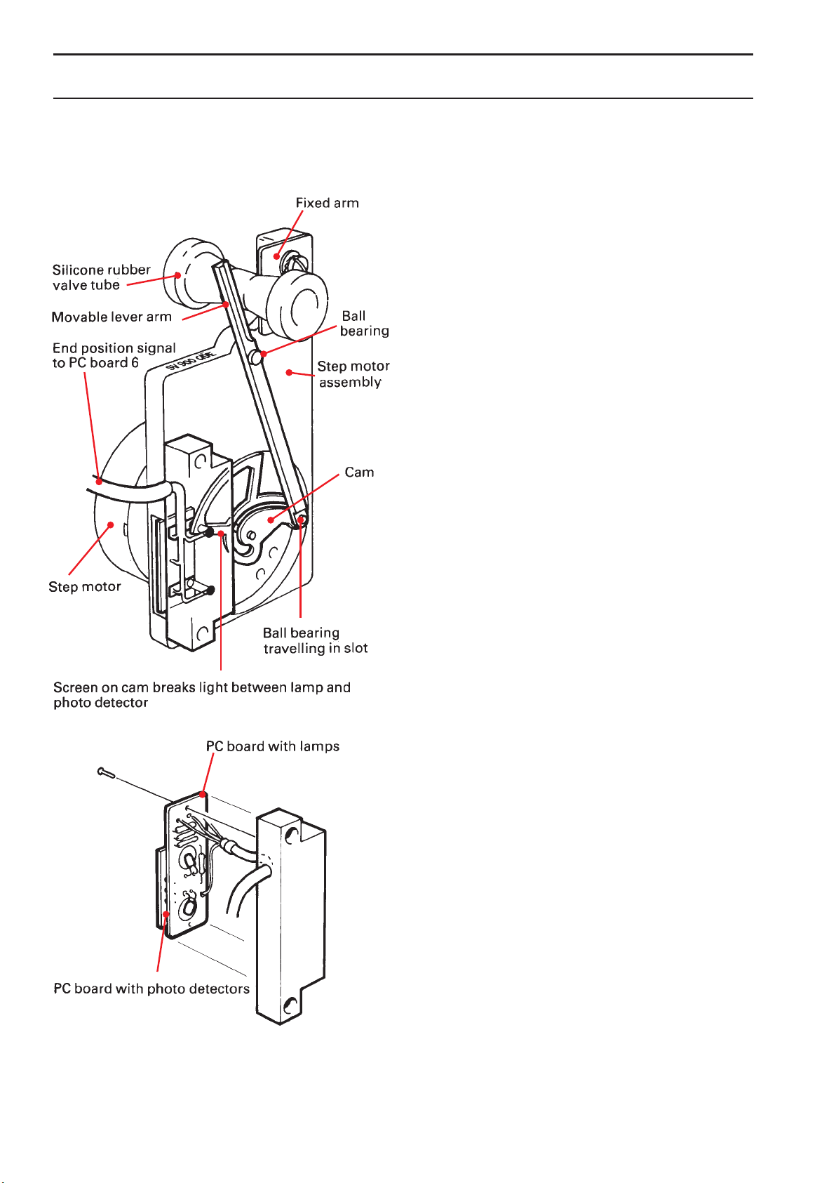
Inspiratory valve and step motor
The inspiratory valve is operated by the step motor via the
logarithmically slotted cam and the lever arm.
When the step motor is in operation, a ball bearing at
the end of the lever arm travels in the slot.
The lever arm squeezes the inspiratory valve
tube against a fixed arm. The change in the flow is
approximately 10% for each step of the step motor,
independent of the motor position as long as the air way
pressure is unchanged.
The step motor has four coils which are fed with
positioning signals from PC board 6 in the electronic unit.
When the mains voltage is switched off (or at mains
voltage failure) the step motor will always end up with the
inspiratory valve in fully opened position.
The maximum speed of the step motor is about 480
steps/second and the time elapsing from fully open to
fully closed position is approximately 0.1 second.
The plastic case contains two PC boards, one with
two miniature lamps and the other with two photo
detectors. When the step motor reaches either end
position of the cam slot, the light beam between the lamp
and the photo detector is interrupted by the cam screen.
This will generate an end position signal for the electronic
circuits on PC board 6.
The position of the lamps in relation to the screen is of
the utmost importance. If the lamps by any chance come
out of position, this will cause the step motor to “rattle”
because end positions are not pro perly indicated. The
same symptom occurs if a lamp is damaged.
Page 17
17
Pneumatic unit
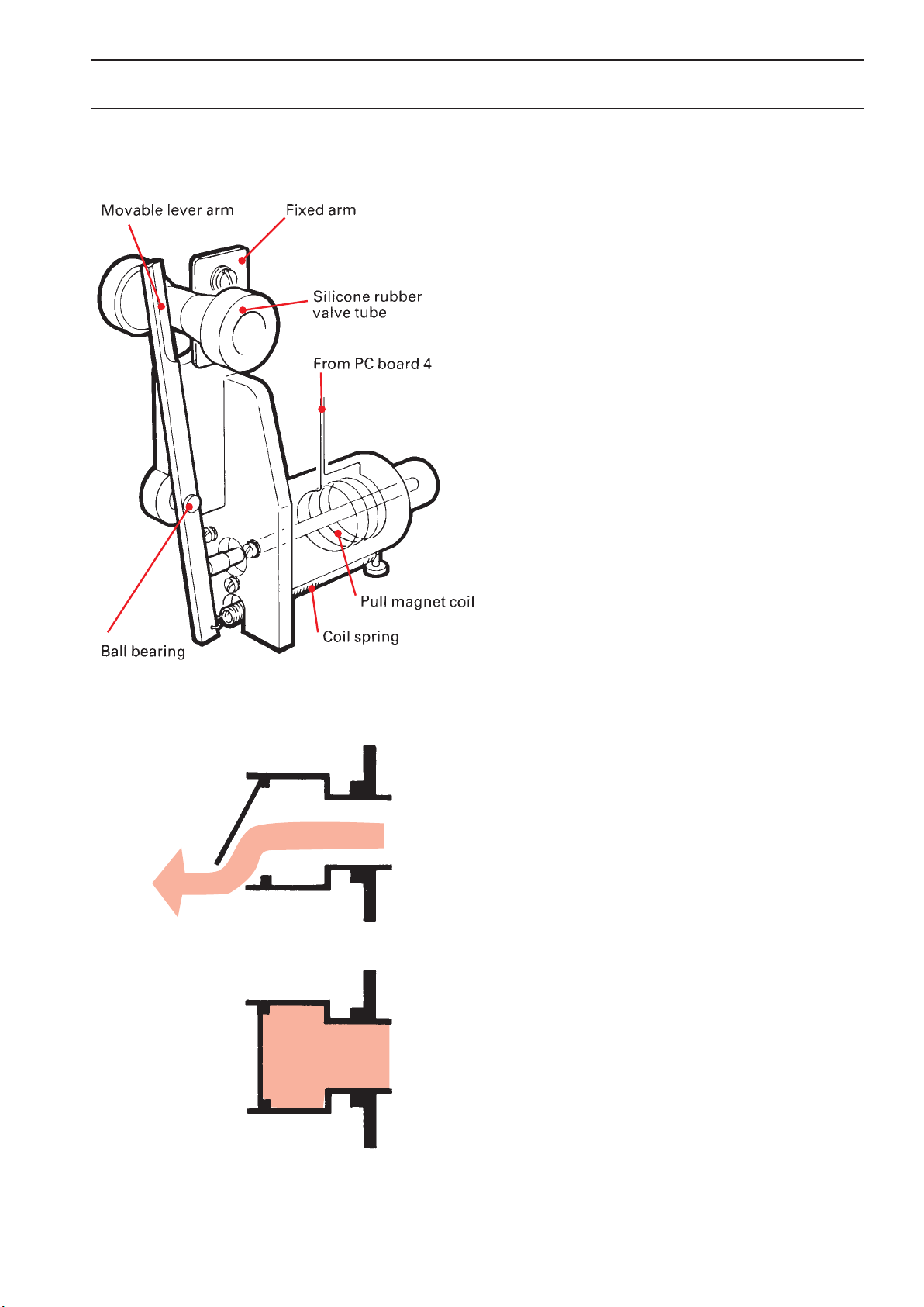
Expiratory valve and pull magnet
The expiratory valve comprises a pull magnet acting on
a lever arm which squeezes a silicone rubber valve tube
against a fixed arm. The valve will close when the magnet
is activated. When the supply current to the magnet is
removed, the valve will open fully be cause of the spring.
This ensures that the patient can always exhale through
the ventilator at voltage failure.
The expiratory valve is controlled by the signals from
the electronic unit. At a PEEP setting, the in formation
from the pressure transducer in the expiratory channel
regulates the valve position during expiration.
Non-return valve
The purpose of the flap valve is to prevent air from entering
the patient circuit through the expiratory channel.
The valve is a vital part of the triggering function
since a patient trig is sensed in the expiratory chan nel
(pressure drop).
➡
Page 18

18
This PC board comprises the preamplifiers for INSP. FLOW
and EXP. FLOW, the amplifiers for AIRWAY PRESSURE (I),
AIRWAY PRESSURE (E) and O
2
CONCENTRATION.
The INSP.FLOW WORKING POINT INDICATOR,
EXP.FLOW WORKING POINT INDICATOR and the 6.8V
REGULATOR and its 6.8V REGULATOR MONITOR are
also included on this PC board.
The CALIBRATION POTENTIOMETERS and the
CALIBRATION SWITCH are situated on this PC board.
On failure in the 6.8V REGULATOR indicated by the
6.8V REGULATOR MONITOR block, the block AIRWAY
PRESSURE (I ) AMPLIFIER will be influenced to generate
a high AIRWAY PRESSURE (I) signal which will result in
UPPER PRESSURE ALARM condition.
Transducer interface (PC board no 11)
Pneumatic unit
Page 19

19
The electronic unit contains the various electronic circuits
for regulation and monitoring. A general description is
found in chapter Introduction and the following chapter
comprises a detailed description of the PC boards
included in the electronic unit.
Electronic unit – Principle of operation
Page 20

20
Electronic unit – Reference level generation
General
The front panel settings are converted to reference level
signals for the regulating systems.
Page 21

21
Electronic unit – Reference level generation
Description of block diagram
The text also refers to the circuit diagrams.
Insp. press. level generation
(PC board no 5)
The input signal is the command value INSP. PRESSURE
LEVEL SET (0-2.5V) from the front panel knob INSP.
PRESS LEVEL ABOVE PEEP (0-100 cm H
2
O). The
command value can be overruled by an input voltage
(0-2.5V) supplied to the rear panel CONTROL TERMINAL
(N28:25), INSP. PRESS. EXTERNAL
The output (V21:8) represents the INSP. PRESS.
LEVEL ABOVE PEEP (0–100 cm H
2
O).
Peep level generation (PC board no 4)
The input signal is the command value PEEP LEVEL SET
(0-2.5V) from the front panel knob PEEP (-10 —+50 cm H
2
O).
The command value can be overruled by an input voltage
(0-2.5V) supplied to the rear panel CONTROL TERMINAL
(N28:13), PEEP LEVEL EXTERNAL.
The output (V6:8) represents the value PEEP LEVEL
(-10–+50 cm H
2
O).
Gas change pressure ref. level
(PC board no 5)
The input signal GAS CHANGE (LO) comes from the front
panel pushbutton GAS CHANGE:
As long as the pushbutton is depressed a reference
value (V17:8 via V2), corresponding to a constant
inspiratory pressure level (+20 cm H
2
O), will be fed to the
block INSP. PRESSURE REF. LEVEL (V18:3).
Insp. minute volume ref. level
(PC board no 8)
This block is used for generation of a reference level.
The normally (+5V ), constant output value INSP.
MINUTE VOLUME REF. LEVEL, can be externally influenced when applying a voltage of -5 to +5 V at the rear
panel CONTROL TERMINAL (N28:12), MINUTE VOLUME
EXTERNAL.
Man vent. filling flow ref. level
(PC board no 7)
This block consists of the resistors R14 – R16, setting
the costant
MAN. VENT. FILLING FLOW REFERENCE
(+1.15 V) for the filling flow to the breathing bag during
manual ventilation. During MAN mode this is used as
the desired INSP. FLOW value for the filling flow to
the manual breathing bag. The resulting momentary
filling flow value is equal to 3 ×
PRESET INSP. MINUTE
VOLUME
(front panel setting).
Example:
PRESET INSP. MINUTE VOLUME
set at 6 l/min
gives a filling flow of 3 × 6 l/min = 18 l/min = 0.3 l/s.
= Not valid for SV 900 E
Page 22

22
Electronic unit – Reference level generation
Ref. level adjust
(front panel; INSP. TIME % selector)
In this block, the constant (normally+5V) value from INSP.
MINUTE VOLUME REF. LEVEL is converted into INSP.
TIME ADJUSTED REFERENCE LEVEL by the voltage
divider on the front panel selector.
The square wave reference signal as well as the
accelerating flow reference signal is inversly propor tional
to the preset INSP. TIME %, since a constant tidal volume
(area) should be maintained regardless of the setting of
the INSP TIME % front panel knob. See dia gram.
If the set respiratory rate increases, the tidal volumes decreases, so that a constant minute volume
is maintained regardless of the respiratory rate. See
diagram.
Constant flow pattern (PC board no 5)
Inputs are INSP. TIME ADJUSTED REFERENCE LEVEL and
the digital control signal INSP. TIME.
The output, (V23:8), is the reference value (negative) used in the block ACCELERATING FLOW PATTERN
and during INSP. TIME as a reference value ( V31)
CONSTANT FLOW PATTERN to the INSP. FLOW ERROR
CALCULATOR and to the VOLUME COMPENSATOR.
Accelerating flow pattern (PC board no 5)
The reference signal (V23:1) ACCELERATING FLOW
PATTERN is generated during INSP. TIME.
The accelerating flow pattern reference signal rises
with a constant slope (staircase generator) during the first
two thirds of the ispiration time. During the remainder of
the ispiration time, the reference signal decreases. See
the diagram, in which the corresponding CONSTANT
FLOW PATTERN reference signal is also indicated.
The maximum amplitude (B) of the accelerating flow
signal is approximately 50% higher than the amplitude
(A) of the square-wave shaped signal. NOTE! Both on the
front panel and in the diagrams, the square-wave shaped
flow reference signal and the accelerating flow reference
signal are represented as positive-going signals. In
reality, these signals are negative-going.
= Not valid for SV 900 E
= Not valid for SV 900 D
Accelerating flow pattern (PC board no 5)
The reference signal (V23:1) ACCELERATING FLOW
PATTERN is generated during INSP. TIME.
The accelerating flow pattern reference signal rises
with a constant slope (staircase generator) during the first
two thirds of the inspiration time. During the remainder
of the inspiration time, the reference signal decreases.
See the diagram, in which the corresponding CONSTANT
FLOW PATTERN reference signal is also indicated.
The maximum amplitude (B) of the accelerating flow
signal is approximately 50% higher than the amplitude
(A) of the square-wave shaped signal. NOTE! Both on the
front panel and in the diagrams, the square-wave shaped
flow reference signal and the accelerating flow reference
signal are represented as positive-going signals. In
reality, these signals are negative-going.
Insp. time
Time
A
B
2/3 of insp. time
Flow
Page 23

23
Electronic unit – Regulation of inspiration
General
The regulation of inspiration is done by means of the
FLOW or PRESSURE SERVO LOOP depending on
selected mode.
The actual values for the controllers in these loops
come either from the inspiratory flow transducer or the
pressure transducers.
Page 24

24
Electronic unit – Regulation of inspiration
Page 25

25
Electronic unit – Regulation of inspiration
Description of block diagram
The text also refers to circuit diagrams.
Insp.flow linearization (PC board no 5)
The signal INSP. FLOW PREAMPLIFIER, is a non-linear
function of the flow in the inspiratory channel. The signal is
linearized in this block.
The linearized output signal (V22:8), represents a
linear measure of the momentary flow in the inspira tory
channel.
INSP. FLOW is also fed to the 15-pole connector for
auxiliary equipment at the rear panel.
Zero-setting insp. flow (PC board no 5)
To prevent offset voltage drift in the INSP. FLOW sig nal, the
INSP. FLOW LINEARIZATION amplifier is ac coupled and
set to zero by the zero setting circuits (V42 and V30) during
the pause and expiratory time periods, except at the very
first moment of the pause, i.e. until the inspiratory valve
has closed.
Insp. minute volume adjustment
(PC board no 5)
In the INSP. MINUTE VOLUME ADJUSTMENT block
(V24:7), the INSP. FLOW signal is scaled to correspond
to the setting of the PRESET INSP. MIN. VOL. l/min potentiometer. Increasing PRESET INSP. MINUTE VOLU ME
will give increasing attenuation of the INSP. FLOW signal in
this block.
Volume compensator (PC board no 5)
The volume compensation is achieved in the follow ing
way: The difference between the adjusted flow signal INSP.
FLOW SCALED and the reference flow sig nal is integrated
(V24:14), resulting in a measure of the volume difference
(volume=integrated flow).
This resulting volume difference will influence the
momentary inspiratory flow in order to maintain an INSP.
MINUTE VOLUME according to PRESET INSP. MIN. VOL.
l/min setting.
During VOL. CONTR. and VOL. CONTR. + SIGH
modes the desired MINUTE VOLUME will thus be
achieved within approximately 8 breaths from each
change of ventilation parameter (at ventilator and/or
patient).
During SIMV AND SIMV + PRESS. SUPPORT modes,
the VOLUME COMPENSATOR will accomplish compensation within each mandatory inspiration only.
Volume compensation selector
(PC board no 5)
The actual value from either MAN. VENT. VOLUME
COMPENSATOR or the common VOLUME
COMPENSATOR is choosen (by V25:6,11) in this stage.
Man. vent. volume compensator
(PC board no 7)
During manual ventilation mode, the volume compensation
for filling of the breathing bag is calculated in this block
(V1a, V1b).
Insp. flow error calculator
(PC board no 5)
The INSP. FLOW ERROR CALCULATOR is enabled by a
control signal from the block CONSTANT FLOW PAT TERN
(V32) during INSP. TIME.
The positive going INSP. FLOW SCALED value (differentiated via C5/R72+proportional via R71) is added to
the negative going SELECTED FLOW REFERENCE and
the VOLUME COMPENSATION value from the VOLUME
COMPENSATION SELECTOR, resulting in the INSP.
FLOW ERROR SIGNAL (V24:1) to the ERROR SIGNAL
SELECTOR. During pause and expiration, the INSP.
FLOW ERROR CALCULATOR is blocked by the control
signal from the block CONSTANT FLOW PATTERN (V32)
which then keeps the ERROR SIGNAL at a fixed negative
level.
Flow pattern selection (Front panel)
The FLOW PATTERN SELECTION is made on the front
panel with the FLOW PATTERN SWITCH and also by the
MODE SELECTOR which will give a constant flow during
mandatory inspirations in SIMV modes and also a constant
filling flow to the manual breathing bag during MAN mode.
= Not valid for SV 900 E
= Not valid for SV 900 D
Page 26

26
= Not valid for SV 900 E
= Not valid for SV 900 D
Insp. pressure ref. level (PC board no 5)
The block outputs are INSP. PRESSURE REFERENCE
LEVEL (V25:3) and the negative going INSP. PRESSURE
REFERENCE (V18:1).
At SIMV + CPAP MODE (V27:12), both block outputs
correspond to PEEP LEVEL (V25:2) coming from PC
board no 4.
In the modes SIMV + PRESS. SUPPORT, PRESS
CONTR. and PRESS SUPPORT, both block outputs
correspond to the sum of PEEP LEVEL and INSP. PRESS
LEVEL (V21:14).
During SIMV +PRESS SUPPORT and PRESS
SUPPORT and CAP modes (V20:14) at INSP. PRESS
LEVEL front panel settings below 8 cm H
2
O, the negative
going INSP PRESS. REFERENCE LEVEL is increased
(V21:7) with 1 cm H
2
O,
When the button GAS CHANGE is activated, the block
GAS CHANGE PRESSURE REF. LEVEL delivers a voltage
corresponding to +20 cm H
2
O at the negative going INSP.
PRESSURE REFERENCE output (V18:1).
Insp. press. level compensator
(PC board no 5)
During PRESSURE REG. INSP. TIME the INSP. PRESSURE
LEVEL COMPENSATOR connects the sum of the negative
going INSP. PRESSURE REFERENCE and AIRWAY
PRESSURE (E) during MID. INSP. TIME PULSE (switch
V47), to the integrator V36/C20. From the integrator the
signal is fed to the INSP PRESS. ERROR CALCULATOR
where com pensation for deviations in actual pressure
value, with respect to desired pressure level, takes place.
At mode change, START UP RESET pulse resets the
integrator (V46).
Second half insp. time (PC board no 7)
A positive going pulse is generated when the time elapsed
during the present INSPIRATION is equal to half of the total
time of the foregoing INSPIRATION.
Mid. insp. time pulse (PC board no 5)
The positive front edge of the pulse generated in SECOND
HALF INSP. TIME will trigger a pulse (V1, V16) which is fed
to INSP. PRESSURE LEVEL COMPENSATOR.
Start insp. time marker (PC board no 5)
A pulse is generated at the beginning of the inspira tion
time, This pulse is used for the derivating circuit in the
block INSP. PRESS. ERROR CALCULATOR, in the block
INSP. PRESSURE ERROR AMPLIFICATION SELECTION
and in the block END INSP. INDICATOR.
Insp. pressure error calculator
(PC board no 5)
The actual AIRWAY PRESSURE (I) value (via R95) is added
to the differentiated AIRWAY PRESSURE (E) value (via
C18/R135/V28), together with the integrated AIRWAY
PRESSURE (E) compensation value from INSP. PRESSURE
LEVEL COMPENSATOR (V36:6 via R94) and the negative
going INSP. PRESSURE REFERENCE (V18:1 via R93)
resulting in the INSP. PRESSURE ERROR SIGNAL (V19:8)
to the ERROR SIGNAL SELECTOR.
Insp. press. error ampl. selection
(PC board no 5)
This stage selects the gain depending on selected mode
and timing signals.
Error signal selector (PC board no 5)
This electronic switch (V26, V27) selects the INSP.
PRESSURE ERROR SIGNAL for the pressure servo loop
and the INSP. FLOW ERROR SIGNAL for the flow servo
loop (see introduction chapter “Regulation of inspira tion”).
Voltage controlled oscillator
(PC board no 6)
The VOLTAGE CONTROLLED OSCILLATOR converts the
error signal into a pulse sequence (speed signal at V5 via
V3:7, 8) with a variable frequency which is propor tional
to the error signal voltage. In addition, there is a direction
signal (at V4 via V3:1) which, depending on the polarity of
the error signal, decides whether the motor should step
forward (opening) or backward (closing).
Electronic unit – Regulation of inspiration
Page 27

27
= Not valid for SV 900 E
= Not valid for SV 900 D
Direction & speed selection
(PC board no 6)
This is a multiplexer and the output signals are direc tion
and speed. The output signals come from the VOLTAGE
CONTROLLED OSCILLATOR during normal operation,
from FAST OPENING OSCILLATOR during beginning of
INSP. TIME in all PRESSURE REG. CONDITIONS except
PRESS. CONTR. mode, and from POWER OFF OPENING
OSCILLATOR when mains is switched off or at power
failure.
Fast opening oscillator (PC board no 6)
This oscillator is set (R37) to a frequency corre sponding to
a step motor speed of approximately 480 steps/second.
Fast opening control (PC board no 6)
This stage will initiate a fast opening of the inspira tory
valve at the beginning of each PRESSURE REG. INSP.,
except during PRESS. CONTR. mode. This condition will
be kept up until the INSP. FLOW exceeds 0.17 l/second.
Power off voltage (PC board no 6)
This stage delivers stored energy to control the ope ning
of the inspiratory valve (step motor) when the mains is
switched off.
Power off opening oscillator
(PC board no 6)
The freqency of this oscillator is selected (R92) within
250-400 Hz.
Electronic unit – Regulation of inspiration
End position protector (PC board no 6)
The purpose of the END POSITION PROTECTOR (V27) is
to stop the VOLTAGE CONTROLLED OSCILLATOR when
the step motor is at either of the two end positions and
the direction signal indicates that the motor should step
beyond these positions.
The VOLTAGE CONTROLLED OSCILLATOR is
blocked if one of the following conditions is fulfilled:
• The inspiratory valve is fully open and the direc tion
signal indicates additional opening.
• The inspiratory valve is fully closed and the direc tion
signal indicates additional closing.
• The inspiratory valve is fully closed and the in spiration
time signal is low.
Step motor driver (PC board no 6)
The STEP MOTOR DRIVER is an up-down counter
(consisting of C-MOS circuits V22 and V23 and an
output buffer stage V24). The driver stage receives speed
information (the pulse frequency) and direction information
(forward or backward) via DIRECTION AND SPEED
SELECTION block. The driver stage has 8 outputs, two
for each motor winding. The windings are activated in a
specific sequence, so that the step motor will move an
angle of rotation of 3.75° at each step (positioning).
Page 28

28
= Not valid for SV 900 D
Electronic unit – Timing
General
The circuits in the main block TIMING deliver signals of
fundamental significance for the respiratory cycle, i.e. the
inspiratory phase (INSP. TIME), the pause pe riod and the
expiratory phase (EXP. TIME), see the diagram below.
The INSP. TIME and PAUSE TIME are set on the front
panel as percentages of the complete respiratory cycle.
The EXP. TIME represents the remainder of the cycle to
100%, equal to 100 clock pulses.
The intervals are controlled by a clock pulse generator.
The percentage settings of INSP. TIME and PAUSE
TIME represent the number of clock pulses to be counted
in each respiratory cycle.
The normal respiratory cycle of 100 clock pulses can
be interrupted in different ways.
See description of block diagram (Insp. time and exp.
time generator) page 30.
Page 29

29
= Not valid for SV 900 E
= Not valid for SV 900 D
Electronic unit – Timing
“MODE”
In the entire BLOCK DIAGRAM, the designation MODE
represents one or more of the following 13 output
signals from the MODE CONTROL BLOCK:
PRESS.REG.INSP TIME
PRESS.REG.CONDITION
PRESS.SUPP.MODE SET (LO)
PRESS. CONTR. MODE SET (LO)
VOL. + SIGH MODE SET (LO)
VOL. CONTR. MODE SET (LO)
SIMV+P. MODE SET (LO)
SIMV MODE SET (LO)
SIMV MODE (LO)
CPAP MODE SET (LO)
SIMV + CPAP MODE
MODE CHANGE
MAN. VENT. MODE SET (LO)
Page 30

30
Electronic unit – Timing
= Not valid for SV 900 E
= Not valid for SV 900 D
Description of block diagram
The text also refers to circuit diagrams.
Clock pulse generator (PC board no 3)
The CLOCK PULSE GENERATOR is a voltage controlled
oscillator controlled by the BREATHS/min setting on
the front panel. The voltage range is from 0 to +5V
corresponding to 5–120 breaths/min. Normally, there will
be 100 clock pulses in each breath. Example: A setting of
60 breaths/min corresponds to a frequency of 100 Hz. The
width of a clock pulse is approxi mately 0.1 ms regardless
of the clock frequency. The frequency can be externally
controlled (via analogue input) or the output signal CLOCK
(V44:1) may be externally controlled (via digital input).
The output MASTER CLOCK ( LO) is used externally
when two ventilators are synchronized.
Sigh counter (PC board no 3)
The SIGH COUNTER (V24 and V25), counts the number of
breaths (positive going edge of the INSP. TIME signal). In
the VOL. CONTR. + SIGH mode, the sigh counter delivers
a high signal for every hundredth breath during inspiration.
This output signal results in a doubling of the clock pulse
cycle time during the ”sigh inspiration”.
Insp. time and exp. time generator
(PC board no 3)
The INSP. TIME AND EXP. TIME GENERATOR consists of
an insp. and pause time counter (V2, V5), and the flip-flops
(V8) for INSP. TIME and EXP. TIME.
In normal controlled MODE operation the following
occurs:
• EXP. TIME ends and INSP TIME starts after every
100th clock pulse (V9 ) or at a command from SIMV
TIMING ( V27:11).
• INSP TIME ends when the number of clock pulses
preset on the INSP. TIME % knob bave been emitted.
• EXP. TIME starts when the number of clock pulses
preset on the PAUSE TIME % have also been emitted.
• A time limitation is always active, except in CPAP
or MAN mode and in spontaneous inpiration during
SIMV mode: EXP. TIME will be started if the time
since the start of INSP. TIME corresponds to 81%
of a breath cycle (V6:3), according to the front panel
setting BREATHS/min. This start expiration condition
is mentioned on page 32. Also refer to the Operating
Manual, page 2:5 (safety function).
The clock pulses are gated (V6:10) with the INSP.
TIME signal, resulting in the signal INSP. TIME × CLOCK
(LO), which is used to generate the reference flow signals,
see Reference level generation.
The normal timing pattern can be interrupted by the
commands PATIENT TRIG. ( V27: 12), UPPER PRESS.
EXCEEDED (V11:6), START EXP. SPONT (V17:13),
PAU SE HOLD (V11:1), SLAVE START INSP. (V8:4,10), and
COUNTER RESET (via R76).
The MASTER START INSP ( V7:10) signal is used
ex ternally when two ventilators are synchronized.
Insp. time & expo time multiplexer
(PC board no 3)
This block is controlled by a MODE-signal. In manual
ventilation, the signals from the INSP. TIME & EXP.
TIME GENERATOR are disconnected and instead the
signals from MAN. VENT. TIMING are connected.
Pause hold (PC board no 3)
This stage is controlled by the knobs INSP. PAUSE HOLD
and EXP. PAUSE HOLD. When any of these but tons is
depressed, the signal PAUSE HOLD. (V19:31 stops the
clock pulse to the INSP TIME & EXP. TIME GENERATOR.
synchronized with the respiratory cycle.
SIMV pulse generator (PC board no 3)
This is the same kind of voltage controlled oscillator as the
CLOCK PULSE GENERATOR. The signal is divi ded by 100
(V35) and furthermore by 10 (V36), controlled by the switch
HIGH RATE/LOW RATE
The main output signal from this stage is the START
SIMV CYCLE pulse to SIMV TIMING. One pulse is emitted
for each SIMV period.
SIMV Timing (PC board no 3)
During SIMV modes, this block will make sure that one
mandatory breath (which means a FLOW REGULATED
INSPlRATION) is started during each SIMV-period.
Each START SIMV CYCLE pulse from the SIMV
PULSE GENERATOR (V34:10), starts a new SIMV-period
which means a synchronizing WAIT-period, waiting for the
next mandatory breath to be initiated. The WAIT-period
will end if there is a PATIENT TRIG (via V27:5), or at the
latest (via V27:4), when 90 clock pulses from the CLOCK
PULSE GENERATOR (V 44:1) have been counted (V30).
In both cases, the SIMV MANDATORY BREATH TRlG
(V27:7), will initiate the mandatory breath with a FLOW
REGULATED INSPIRATION. During (SIMV)-spontaneous
breathing, the command PRESS REG. PRECONDITION
(V26:12) will enable the PRESSURE SER VO LOOP instead
of the FLOW SERVO LOOP.
The SIMV BREATHS/min setting is compared with the
BREATHS/min setting in comparator V37. This ensu res
that when the SIMV RATE is set at a rate, higher than the
BREATH RATE SET, the resulting BREATH RATE will be
the one coming from BREATHS/min setting.
Mode control (PC board no 3)
In combination with the mode selector on the front panel,
this block generates 13 different so called MODE signals
used in several places in the ventilator. (Signal names in
the INTERCONNECTION DIAGRAM and table on page 29).
Mode change indicator (PC board no 6)
A START UP RESET pulse is generated at mode change,
power on and gas change. The result of the COUNTER
RESET pulse also generated at mode change and
gas change is to reset the 2 minute timer and that the
expiration starts immediately. This expiration will be 100
clock pulses long if there is no patient trig.
Page 31

31
= Not valid for SV 900 E
= Not valid for SV 900 D
Electronic unit – Timing
End insp. indicator (PC board no 5)
In all modes which include spontaneous breathing.
(PRESS SUPPORT, SIMV and SIMV + PRESS. SUPPORT
and CPAP the moment when the spontaneous inspiration
is about to stop is normally determined in this stage (a
START EXP. SPONT signal is generated).
Criteria no 1. for this is when the measured flow drops
below 25% (V22: 2/R53. R76) of the PEAK FLOW during
the same inspiration ( V16:1/C13) if the PEAK INSP. FLOW
is higher than 0.1 l/second.
Closed inspiratory valve and a pressure increase of
+3 cm H
2
O will also result in a STARTEXP SPONT. signal
to INSP. TIME & EXP. TIME GENERATOR (criteria no 2).
This signal makes INSP. TIME end even if the peak insp.
flow is lower than 0.1 l/s.
See table on page 32.
Man. vent. timing (PC board no 7)
This stage receives the AIRWAY PRESURE (I) signal from
the inspiratory pressure transducer. This signal goes to the
comparator (V1d:12, 13, 14) which controls the manual
ventilation EXP. TIME., and to (V1c:10, 9, 8), which controls
the manual ventilation INSP. TIME.
The INSPIRATION TIME in this case, means the time
during which the manual breathing bag will be filled.
This will start when the pressure drops below
approximately 2 cm H
2
O and it will stop when the
pressure rises above approximately 4 cm H
2
O
(comparator V1c).
The expiration will take place if the pressure
drops below approximately 4 cm H
2
O and will stop
if the pressure rises above approximately 6 cm H
2
O
(comparator V1d).
Page 32

32
Electronic unit – Timing
= Not valid for SV 900 E
= Not valid for SV 900 D
The start insp. conditions (V=ventilator and The end insp. conditions (0-5) are monitored in the
P=patient) are monitored in the following blocks: following blocks:
(V) INSP. TIME & EXP.TIME GENERATOR (0): INSP. & EXP. TIME GENERATOR
(PC board no 3) (PC board no 3)
(P) TRIG. LEVEL MONITORING (1): END INSP. INDlCATOR
(PC board no 4) (PC board no 5)
(2): END INSP. INDlCATOR
(PC board no 5)
(3): UPPER PRESSURE MONITORING
P
I
= AIRWAY PRESSURE (I) (PC board no 4)
P
E
= AIRWAY PRESSURE (E) (4): HIGH INSP. PRESS.PROTECTION
Patient TRIG = P
E
< [PEEP LEVEL] – [TRIG SENSITIVITY] (PC board no 5)
(5): INSP. TIME. & EXP. TIME GENERATOR
(PC board no 3)
Mode Start insp. condition End insp. condition *)
PRESSURE (V) Ventilator START INSP. (0) VENTILATOR STOP INSP. Preset INSP. TIME%
CONTROL Preset BREATHS/min.
(P) PATIENT TRIG: (3) P
E
or PI > [UPPER PRESS. LIMIT]‚ Preset UPPER PRESS. LIMIT
Preset TRIG. SENSITIVITY (4) P
I
>[30 cm H2O] + [PEEP LEVEL] + [INSP. PRESS LEVEL above
PEEP]‚
Preset PEEP and INSP. PRESS LEVEL
PRESSURE (PI) Patient TRlG; (1) INSP.FLOW < 25 % × [PEAK INSP.FLOW during same
SUPPORT Preset TRIG. SENSITIVITY inspiration];
or pressure (This condition only at PEAK INSP. FLOW > 0.1 l/s)
regulated (2) [INSP.VALVE CLOSED] & P
E
> ([3 cm H2O] + [PEEP LEVEL] +
inspiration [INSP.PRESS LEVEL above PEEP]);
during SIMV + Preset PEEP and INSP. PRESS. LEVEL above PEEP
PRESS. (3) P
E
or PI> [UPPER PRESS.LIMIT];
SUPPORT Preset UPPER PRESS.LIMIT
(4) P
I
> ([30 cm H2O] + [PEEP LEVEL] + [INSP.PRESS.LEVEL
above PEEP]);
Preset PEEP and INSP. PRESS.LEVEL
(5) Duration of [ INSP.TIME] > (80 % × [BREATH CYCLE]),
Preset BREATHS/ min
CPAP or (P) Patient TRlG; (1) INSP.FLOW < 25 % × [PEAK INSP.FLOW (during same
pressure Preset TRIG SENSITIVITY inspiration)]; only at PEAK INSP.FLOW >0.1 l/s
regulated (2) [INSP.VALVE CLOSED] & P
E
> ([3 cm H2O] + [PEEP LEVEL]);
inspiration Preset PEEP
during SIMV (3) P
E
or PI> [UPPER PRESS.LIMIT];
Preset UPPER PRESS.LIMIT
(4) P
I
> ([30 cm H2O] + [PEEP LEVEL];
Preset PEEP
VOL. CONTR. (V) Ventilator START INSP.; (0) Ventilator STOP INSP.;
(+SIGH) Preset BREATHS/min Preset INSP: TIME%
or flow (P) Patient TRIG; (3) (P
E
or PI) >[UPPER PRESS. LIMIT ];
regulated Preset TRIG SENSITIVITY Preset UPPER PRESS . LIMIT
inspiration
during SIMV
(+PRESS.
SUPPORT)
Start insp. & end insp. conditions, and the front panel settings on which they depend
*) The conditions 1-5 lead directly to start of expira tion.
The condition 0 leads to PAUSE. Preset PAUSE TIME%.
Start expiration condition (safety function) during PAUSE:
(Duration of [INSP.TIME + PAUSE TIME]) > (80% ×
[BREATH CYCLE])
Preset INSP.TIME% + PAUSE TIME%.
This start exp condition is monitored in the same way as end
insp condition 5.
Page 33

33
Electronic unit – Monitoring
General
The monitoring subsystem of the Servo Ventilator
900 C/D/E is used for continuous monitoring and indication, via the front panel meters, of the pressure and flow
signals.
The expiratory flow transducer continuously meas ures
the expiratory flow. The flow is linearized and the value is
shown on the meter EXPIRED MINUTE VOLUME and on
the digital display as EXP. TIDAL VOL. ml and EXP. MIN
VOL. l/min.
The monitoring system operates independent of the
regulating systems.
On the digital display, 8 parameters can be selec ted
for direct read-out.
The values are continuously compared with preset
alarm limits, and if any of these limits is exceeded, a
corresponding visual and audible alarm is activated.
As described in the section TIMING, the timing
schedule is affected when one of the limit values UPP ER
PRESSURE EXCEEDED or PATIENT TRIG. is exceeded.
All internal voltages; and timing control signals are
monitored and an audible alarm is activated if any of
these should fail.
The audible alarms, with some exceptions, can be silenced for approximately 2 minutes by means of the knob
OFF 2 MIN on the front panel. UPPER PRESS.LIMIT and
TIMING FAILURE audible alarm as well as the ini tiation of
an alarm for VOLTAGE failure can not be si lenced in this
way.
Page 34

34
Electronic unit – Monitoring
Page 35

35
= Not valid for SV 900 E
Electronic unit – Monitoring
Description of block diagram
The text also refers to circuit diagrams.
Set O2 alarm limits (PC board no 9)
The settings on the front panel knobs for O2 CONC.
ALARM LIMITS are sensed in this block.
The output signal O
2
CONC. AL ARM UNSET is a
digital signal (V15:10) which will be active ( LO) if:
– the front panel knob LOWER ALARM LIMIT for O
2
CONC. is close to its left (counter clockwise) end
position (out of scale) and/or
– the front panel knob UPPER ALARM LIMIT for O
2
CONC. is close to its right (clockwise) end position (out
of scale).
This output signal (V15:10) activates the yellow lamp
SET O
2
ALARM on the front panel via the block ALARM
LAMP DRIVER.
The output signals furthered to the block O
2
CONC.
MONITORING correspond to:
– O
2
conc. lower limit
– O
2
conc. upper limit
– signal level corresponding to 18% O
2
(21% if R61 =
1 kΩ is in use).
O2 conc. monitoring (PC board no 9)
The input signal is the O2 CONC. from the amplifier for O2
concentration. The scale factor is 50 mV/%.
The signal is compared with the preset alarm limits
from the block SET O
2
ALARM LIMITS. An alarm pulse is
generated to the ALARM LAMP DRIVER (for O
2
CONC.
ALARM) if the signal O
2
CONC. value is:
– less than the setting of the front panel knob
LOWER ALARM LIMIT for O
2
concentration or
– more than the setting of the front panel knob
UPPER ALARM LIMIT for O
2
concentration or
– below 18% independent of front panel setting
(21% if R61 = 1 kΩ is in use).
Set minute volume alarm limits
(PC board no 6)
The settings on the front panel knobs concerning ALARM
LIMITS for EXPIRED MINUTE VOLUME are sen sed in this
block.
The output signal is the signal MINUTE VOL. AL ARM
UNSET (V10-L37&L38) which will be active (HI) if:
– the front panel knob LOWER ALARM LIMIT
for EXPIRED MINUTE VOLUME is close to its
left (counter clockwise) end position (out of scale)
and/or
– the front panel knob UPPER ALARM LIMIT for
EXPIRED MINUTE VOLUME is close to its right
(clock wise) position (out of scale).
The signal MINUTE VOL. ALARM UNSET activates a
flashing yellow light, SET MIN. VOL. AL ARM on the front
panel via the block ALARM LAMP DRIVER.
Exp. minute volume monitoring
(PC board no 6)
The actual value EXP. MINUTE VOL. MONITOR from
the EXP. FLOW AVERAGER and the settings of the front
panel knobs concerning the ALARM LIMITS for EXPIRED MINUTE VOLUME are sensed in the EXP. MINUTE
VOLUME MONITORING block.
The output (V9:7) is the signal EXP. MIN. VOL. LIMIT
EXCEEDED which will be active (HI) if the actual value of
EXP. MINUTE VOL. MONITOR is:
– more than the setting of the front panel knob
UPPER ALARM LIMIT for EXPIRED MINUTE
VOLUME.
– less than the setting of the front panel knob
LOWER ALARM LIMIT for EXPIRED MINUTE
VOLUME.
The signal EXP. MINUTE VOL. LIMIT EXCEEDED
acti vates a red flashing lamp, EXP. MINUTE VOLUME
ALARM, on the front panel and the AUDIBLE ALARM via
the block ALARM LAMP DRIVER.
Gas supply monitoring (PC board no 6)
The actual value of INSP. FLOW from INSP. FLOW LINEARIZATION and the actual value of AIRWAY PRESSURE
(I) from AIRWAY PRESSURE (I) AMPLIFIER as well as
the control signal INSP. VALVE OPENED (LO) from END
POSITION PROTECTOR are sensed.
The output signal (V7:7) GAS SUPPLY FAILURE, will
be active during all modes except MAN. VENT. MODE if
the following occurs at the same time:
– INSP. FLOW is less than 0.3 l/second,
– AIRWAY PRESSURE (I), is less than 22 cm H
2
O and
– INSP. VALVE is fully open.
The signal GAS SUPPLY FAILURE activates the flashing red alarm lamp, GAS SUPPLY ALARM, on the front
panel and the AUDIBLE ALARM via the block ALARM
LAMP DRIVER.
Page 36

36
= Not valid for SV 900 E
Electronic unit – Monitoring
2 minute timer (PC board no 6)
The input signals are AUDIO ALARM TURN OFF (LO) from
the front panel pushbutton OFF 2 MIN and COUN TER
RESET from (R 80) MODE CHANGE INDICATOR.
The output signal (V28:10) AUDIO ALARM 2 MIN OFF,
will be active during (up to) 2 minutes from each time
the pushbutton is depressed. During the active time of
the output signal, the timer can be reset by the signal
COUNTER RESET. The signal AUDIBLE AL ARM 2 MIN
OFF will silence the following alarms for 2 minutes:
EXP. MINUTE VOLUME ALARM
APNEA ALARM
GAS SUPPLY ALARM
O
2
CONC ALARM
Timing monitoring (PC board no 6)
In all modes except the MAN. VENT. MODE the control
signals CLOCK, INSP. TIME, and EXP. TIME are monitored.
The signal TIMING FAILURE (LO) (V28:6), will be
active:
– if more than 0.5 second has passed since the last
start of a CLOCK PULSE or
– if the control signals INSP. TIME and EXP. TIME
should both be active at the same time.
The signal TIMING FAILURE (LO) activates the
AUDIBLE ALARM via the block TIMING & SUPPLY
VOLTAGE MONITORING.
The signal APNEA (LO), (V30: 9), will be active:
– if more than 15 seconds has passed since the last
start of INSP. TIME and/or
– if more than 15 seconds has passed since the last
start of EXP. TIME.
The signal APNEA (LO) activates the red flashing
alarm lamp, APNEA ALARM, on the front panel and the
AUDIBLE ALARM via the block ALARM LAMP DRIVER.
Timing & supply voltage monitoring
(PC board no 9)
In case of TIMING FAILURE, (from TIMING MONITORING)
or if any of the four regulated internal supply vol tages fails,
AUDIBLE ALARM will be activated.
Alarm lamp flash oscillator
(PC board no 9)
This oscillator generates a frequency (approximately 2 Hz)
for lamp flashes and audible alarms.
Alarm lamp driver (PC board no 9)
The input alarm signals are gated together with the signal
from ALARM LAMP FLASH OSCILLATOR causing the
activated alarm lamps to light up and flash.
All alarms, except SET ALARM LIMITS include audible
alarm.
Audible alarm (PC board no 9)
The bleep-tone is driven from V17 or V11. The capacitors C1-C6 supplies the alarm circuit with power for
approximately 5 minutes when mains is switched off or at
mains failure.
Operating time meter (Power supply unit)
The meter reading (on the rear panel), indicates the
accumulated time that the power has been switched on.
Trig. level generation (PC board no 4)
The input signals are, the command value (0—2.5V)
TRIG. SENSITIVITY SET from the front panel knob TRIG.
SENSITIVITY BELOW PEEP (-20—0 cm H
2
O) and the
reference value (-0,5—2.5V) PEEP LEVEL
(-10—+50 cm H
2
O) from PEEP LEVEL GENERATION.
The output signal (V6:1) is the reference value
TRIG. LEVEL, corresponding to the absolute TRIG.
SENSITIVITY value subtracted from the PEEP value.
Page 37

37
Electronic unit – Monitoring
= Not valid for SV 900 E
Trig. level monitoring (PC board no 4)
The signal PATIENT TRIG. (V14:14/L53) and TRIG. LAMP
(V22:16), will both be high each time the actual value
AIRWAY PRESSURE (E) falls below the reference value
TRIG. LEVEL with the following exception:
To prevent trig. while the patient is exhaling, the trig.
is blocked:
– by (VI7:10) during the first 5 seconds after start of
expiration – during expiration only – as long as the actual
EXP. FLOW value is more than 0.05 l/s. (V17 is reset by
START INSP. control signal).
– (via V13:14) if the actual value AIRWAY PRESSURE
(E) has been increasing (V13:1, 7, 8) = oscillating during
expiration.
The signal PATIENT TRIG. is fed to the main block
TIMING and used for start of an inspiration and the signal
TRIG. L AMP (LO) lights the yellow lamp at the TRIG.
SENSITIVITY knob on the front panel.
High insp. pressure protection
(PC board no 5)
The inputs are, PRESS. REG. INSP. TIME (inverted in the
block MID INSP. TIME PULSE), the actual value AIRWAY
PRESSURE (I) and the desired inspiratory pressure value
represented by the negative going INSP. PRES SURE
REFERENCE signal (via R90).
The output signal HIGH PRESSURE STOP INSP.
(VI8:8/L33 ), will be active during PRESSURE REGULATED INSPIRATION (controlled via L13) if the actual value
AIRWAY PRESSURE (I) exceeds the desired inspiratory
pressure value by more than 30 cm H
2
O.
The output signal HIGH PRESSURE STOP INSP.
will initiate a condition to stop the pressure regulated
inspiration and start the expiration.
Upper pressure monitoring
(PC board no 4)
The input signals are HIGH PRESSURE STOP INSP., the
actual values AIRWAY PRESSURE (I) and (E) and the
command value UPPER PRESSURE LIMIT SET from the
front panel knob UPPER PRESS LIMIT (15-120 cm H
2
O)
The output signals UPPER PRESSURE EXCEEDED
(V9:7/L39, or (V23:6/L39) UPPER PRESSURE ALARM
(V22:14) and UPPER PRESSURE ALARM LAMP (V22:15)
will all be active as long as:
– the actual value AIRWAY PRESSURE (I) and/or (E)
exceeds the command value UPPER PRESSURE LIMIT
SET and/or
– HIGH PRESSURE STOP INSP. is active.
The output signal UPPER PRESSURE EXCEEDED is
used for initiating an expiration (in the block INSP. TIME &
EXP. TIME GENERATOR).
The signal UPPER PRESSURE ALARM activates the
AUDIBLE ALARM.
The signal UPPER PRESSURE ALARM LAMP (LO)
lights the red lamp at the knob UPPER PRESS. LIMIT on
the front panel.
Airway pressure instrument selector
This block is a symbol for the function of:
– one part of the CALIBRATION SWITCH (in the
pneu matic unit) and
– one part of the front panel MODE SELECTOR.
The normal output signal corresponds to AIRWAY
PRESSURE (I ) from the inspiratory PRESSURE TRANSDUCER (I). The output signal during MAN. mode or when
the calibration switch is depressed, corresponds to
AIRWAY PRESSURE (E) from the expiratory PRESSURE
TRANSDUCER (E).
Page 38

38
Electronic unit – Monitoring
= Not valid for SV 900 E
= Not valid for SV 900 D
Airway pressure panel meter
The panel meter for AIRWAY PRESSURE displays the
inspiratory or expiratory pressure, depending on the
selected mode and the calibration switch.
Exp. flow linearization (PC board no 4)
The signal from the expiratory flow transducer is linearized
(by V8:1).
Zero setting exp. flow (PC board no 4)
To prevent offset voltage drift in the EXP.FLOW sig nal, the
EXP. FLOW LINEARIZATION amplifier is ac coupled and
set to zero during inspiration and pause by means of the
zero setting circuit (V19). Zero setting also takes place in
this block (by V18) when the GAS CHANGE pushbutton is
depressed.
Flow averager (PC board no 7)
The FLOW AVERAGER is a low pass filter. Its time con stant is depending on the CLOCK-frequency (preset
BREATHS/min on the front panel). The output EXP.
MINUTE VOL (0.2 V/l/min) is the mean value of the
input EXP.FLOW (-7.2 V/l/s). The outputs EXP. MINUTE
VOL. INSTRUMENT (front panel meter) and EXP. MINUTE
VOL. MONITOR (V14:1) are influenced by the switch
INFANTS/ADULTS which will increase the sensitivity by ten
times in the INFANTS range.
Expired minute volume panel meter
The panel meter showing EXPIRED MINUTE VOLUME has
two scales (0–4 and 0–40 l/min).
Calculation timing (PC board no 7)
This block produces timing signals for the different
calculating stages.
Integrator (I) (PC board no 7)
The INSP TIDAL VOLUME is an integration of the INSP.
FLOW signal during each inspiration.
Integrator (E) (PC board no 7)
The EXP. TIDAL VOLUME is an integration of the EXP.
FLOW signal during each expiration.
Ripple reduction (PC board no 7)
This is a special low pass filter, creating a stable output
value (V34:5), EXP. MINUTE VOL. (0.2 V/l/min; 2 V/l/min).
The output (EXP. MINUTE VOL. DISPLAY) can be shown on
the DIGITAL DISPLAY at the front panel.
End insp. pressure hold (PC board no 7)
This block is an analogue memory.
The PEAK PRESSURE is the AIRWAY PRESSURE (E)
va lue at the end of inspiration.
End pause pressure hold (PC board no 7)
This block is an analogue memory.
The PAUSE PRESSURE is the AIRWAY PRESSURE (E)
value at the end of the pause.
Pressure averager (PC board no 7)
The PRESSURE AVERAGER is a low pass filter. Its time
constant is depending on the frequency of the stret ched
CLOCK pulses (by V9:10 in the block CALCULA TION
TIMING) (preset BREATHS/min on the front panel).
The output MEAN AIRWAY PRESSURE is a mean
value of the AIRWAY PRESSURE (E)
Resp. rate calculator (PC board no 7)
Thc RESP. RATE (CALCULATED) is an analogue frequency value corresponding to a “beat to beat” time of each
respiratory cycle.
Display control (PC board no 1)
Via the front panel selector for DISPLAY PARAMETER,
– the parameter to be shown is selected
– the decimal point position is influenced by the front
panel switch INFANTS/ADULTS (for EXPIRED MINUTE
VOLUME) and
– the blanking of the DVM/DISPLAY is influenced by O
2
CELL CONNECTED and during MAN. mode.
DVM/Display (PC board no 1)
This is a Digital Volt Meter with 3½ digits. Depending on
the front panel selector for DISPLAY PARAMETER one
out of eight analogue parameters will be displayed as a
corresponding digital value.
Page 39

39
Electronic unit – Regulation of expiration
General
The pressure signal from the pressure transducer in the
expiratory channel is compared with the pre set PEEP
level, and a difference results in a correction signal to the
expiratory valve to maintain the set PEEP level.
Page 40

Electronic unit – Regulation of expiration
Description of block diagram
The text also refers to the circuit diagrams.
Active filter (PC board no 4)
The AIRWAY PRESSURE (E) signal is filtered with re spect
to 40 Hz signal (ripple), from expiratory valve.
Peep error calculator with peep
compensator (PC board no 4)
The PEEP level signal from PEEP LEVEL GENERATION
(V6:8 via R18) is added to the actual inverted value of
AIRWAY PRESSURE (E) from ACTIVE FILTER (V8:8 via
R17) which gives the proportional action (via R21) for
the PEEP regulation. The proportional action has two
levels of amplification. The higher level of ampli fication
is intended to increase the opening of the ex piratory
valve during the very first 50-70 ms of EXP. TIME. During
the rest of EXP. TIME the normal level of amplification is
used (activated via V2 by control sig nal from V5:14). An
additional activating circuit (V25 controlled from the signal
INFANTS RANGE SET (LO) at P4:22A) results in the normal
level of amplification being used continuously during the
entire EXP. TIME if the EXP. MINUTE VOLUME is less than
approximately 4 l/min (comparator V12:14) as well as if
INFANTS is selected at the SV 900 C front panel INFANTS/
ADULT switch.
At each breath the difference between actual AIR WAY
PRESSURE (E) (inverted value via R12) and the de sired
PEEP (value via R15) together with a minor in fluence
from EXP. FLOW (value via R58) is (enabled via V16 and)
integrated in the PEEP COMPENSATOR (V10/C21). The
PEEP COMPENSATOR continuously stores a signal level
which is used (via R62) for biasing the PULL MAGNET
COIL during PEEP regulation.
The combined PEEP regulating signal (V11:1) will
influence pull magnet via PULSE WIDTH MODULATION to
obtain the desired PEEP level.
Pulse width modulation (PC board no 4)
The pulse width modulator converts the signal from the
PEEP ERROR CALCULATOR to a pulse sequence with a
fixed frequency.
Pull magnet driver (PC board no 4)
The driver stage converts the pulses into a current through
the pull magnet coil. The pull magnet keeps the expiratory
valve closed during inspiration and pause.
The opening angle of the pull magnet is deter mined by
the width of the current pulses through the coil. The greater
the error signal, the shorter the pulse and consequently,
the bigger the opening angle.
The signal GAS CHANGE causes the valve to open.
Peep compensator timing (PC board no 4)
These are the control circuits for the integrator in the PEEP
ERROR CALCULATOR WITH PEEP COMPENSATOR
block.
The input (V16) of the integrator (V10/C21) of the PEEP
ERROR CALCULATOR WITH PEEP COMPENSATOR block
is switched on (by V17/V9) at the beginning of EXP. TIME. It
will be switched off when the EXP. FLOW is less than 0.014
l/second (by V6:14) or at the latest after 250 ms (by V17/
V9). It is grounded (via V1) during the first 50-70 ms of EXP.
TIME (by V5:14).
Peep security valve opener (PC board no 4)
This stage ensures that the integrator in the PEEP
CALCULATOR WITH PEEP COMPENSATOR block is
discharged (V15) if the pressure exceeds 4 cm H
the set PEEP level (by V11:7).
As the pressure at the beginning of expiration is
normally more than 4 cm H
integrator discharge circuit (V15) is blocked during the first
part of the expiration from PEEP COMPENSA TOR TIMING
(V5:14/L43).
It is also blocked during INSP. TIME and PAUSE TIME
and as long as EXP. FLOW is more than 0.05 l/second
(V14:7 in the block TRIG LEVEL MONITORING).
O above PEEP level, the
2
O above
2
Pull magnet delay (PC board no 4)
A delay pulse of approximately 1.5 s is generated each
time the input signal GAS CHANGE (V5:7) goes low. The
delay pulse goes to the PULL MAGNET DRIVER block.
Thus, each time the front panel knob GAS CHANGE
is released (=at the end of GAS CHANGE), the PULL
MAGNET DRIVER is disabled and the expiratory valve is
kept open during this delay pulse. The time is long enough
for the AIRWAY PRESSURE to drop to a low pressure level.
40
= Not valid for SV 900 D
= Not valid for SV 900 E
Page 41

41
Electronic unit – Voltage supply
General
The Servo Ventilator 900 C/D/E can be connected to mains
110, 120, 220 or 240 V AC 50/60 Hz with a pro tective
ground. (A special version for 100 V AC is av ailable) .
The voltage supply system provides the subsys tems
with supply voltages +24, +5 and ± 15V.
If any of the internal voltage supplies fails, an alarm is
immediately activated.
Transformer (Power supply unit)
The voltage can be selected internally at the trans former
mains input. There are fuses for the trans former, externally
(in fuse holder) and internally (three thermal fuses).
+24V, +5V, ±15V regulation
(PC board no 10)
The four internal supply voltages are all regulated and
protected against over-voltage at the outputs by diods
(L4, L5, L6 and L 7).
Ref. voltage generation (PC board no 1)
The generated reference voltages ±10V (REF), +5V (REF)
and +2.5V (REF) are used at the front panel potentiometer
controls and on different PC boards.
Page 42

42
Electronic unit – Input/output
General
At the rear panel of the ventilator, there are three 15-pole
Cannon sockets for AUXILIARY EQUIPMENT, a 25-pole
Cannon socket (under a lid): CONTROL TER MINAL and a
37-pole Cannon socket with RECORDER OUTPUTS.
Output buffers (PC board no 8)
The output signals at the 15-pole and 37-pole Can non
sockets are all (except the supply voltages) buffe red for
security.
External control (Rear panel)
The 25-pole socket marked CONTROL TERMINAL is intended for control of some ventilator functions, for instance
when connecting two ventilators in a MAS TER-SLAVE
configuration.
The pins are either for input signals or output signals
(pins 22 and 23 are combined). The inputs are intended
for low-resistance (less than 100 ohm) voltage, lower
than ±12V. Higher voltages might be hazardous to the
electronic circuits and must not be used.
Page 43

43
Electronic unit – Input/output
Recorder output
The recorder output (37-pole Cannon), contains outputs for
flow, pressure and some control signals. The outputs are
adapted to Ming ograf recorders.
The pins (1—37) of the connector are numbered
101—137 in the diagrams.
Auxiliary equipment
The 15-pole Cannon connectors, three in parallel, contains
outputs for flow and pressure and some control signals.
The pins (1—15) of three connectors are numbered
301—315, 401—415 and 501—515 in the diagrams.
Control terminal
The 25-pole Cannon connector contains inputs for external
control of some functions as well as output signals.
The pins (1—25) of the connector are numbered 201—
225 in the diagrams.
Inputs
Pin 7: SLAVE START INSP. (0V; 5V DIGITAL CONTROL)
Pin 8: RESP. RATE=U* × 23 breaths/min/V+5
breaths/min.
Pin 10: SIMV RATE=U* × 14.4 breaths/min/ V+4
breaths/min.
Pin 12: MINUTE VOLUME EXTERNAL
±0.05V ↔ ±1% of set minute volume
Pin 13: PEEP LEVEL=U* × 24 cm H
2
O/V-10 cm H2O.
Pin 21: SLAVE CLOCK (0V;5V DIGITAL CONTROL)
Pin 22: PATIENT TRIG. (0V;5V DIGITAL CONTROL)
Pin 23: UPPER PRESSURE EXCEEDED (0V; 5V DIGITAL CONTROL)
Pin 25: INSP. PRESSURE (ABOVE PEEP)=U* × 40 cm H
2
O/ V.
U*= The on the actual pin supplied voltage. 0 volt should be
co nnected to pin 2 or 14
Outputs
Pin 9: MASTER START INSP. (0V; 5V output)
Pin 11: MASTER CLOCK (0V; 5V output)
= Not valid for SV 900 D
!
CL
DS
BU
!
(
BQ
*
!
BP
CQ
BO
Page 44

44
Pneumatic unit
Electronic unit
Disassembling
Page 45

45
Step motor assembly and pull magnet
Disassembling
Page 46

46
Adjustments
Replacement of flow transducer
The FLOW TRANSDUCER spare part includes a sepa rate
serial number label with the same number as the transducer.
When replacing the FLOW TRANSDUCER, the connection
plug label must be replaced with the new label.
Adjustment of meters Z1 and Z2
• Set Z1 and Z2 to zero mechanically.
Adjustment of valve arm
Pressure plate with plastic tab
These instructions are only applicable for valve arm which
is mechanically actuated by a plastic tab on the pressure
plate.
• Remove the bellows.
• Connect the device to the high pressure gas
supply.
• Push down the pressure plate and release the pres sure until you can clearly hear that the controlled
inlet valve opens.
• With the valve in the nearly open position, the
distance A must be approximately 55 mm.
• If the distance A deviates from 55 mm (i.e the controlled
inlet valve opens too soon or too late), take out the gas
supply unit and carefully bend the lever arm as shown in
the picture.
Pressure plate with magnet
For gas supply unit with covered valve arm activated by
a magnet on the pressure plate, only the magnet on the
pressure plate can be adjusted sideways. See page 11 and
“Magnet kit for Servo Ventilator-Mounting instructions”,
Order no: 91 05 487 E313E.
Page 47

47
Adjustments
Replacement and adjustment of R5
Note – This adjustment is of vital importance
for faultless operation.
• Loosen (but do not remove) the Allen screws on the
control knob. There are two screws on old knobs and
one screw on new knobs.
• Protectthefrontpanelwithasoftcloth.Carefullyinsert
a screwdriver or similar bladed tool behind the scale
unit and lever it away from the front panel. Remove the
complete scale unit.
• PulloutPCboardno2(PC756)toseparateR5
from the electric circuitry of the ventilator during the
adjustment.
• Connectanohmmeterbetweenthetwopinsusedon
R5 and turn the potentiometer shaft until the ohm meter
shows approx. 500 ohms.
• Setthescaleonthescaleunitto1.0andlockthescale
in this position.
• Applyglue(Mega-Firmorsimilar)totheguideholein
the front panel.
• Carefullyputthescaleunitinpositionwithout
allowing the potentiometer shaft to turn.
• TightentheAllenscrews.
• Checkthattheresistancebetweenthetwopinsused
on R5 is from 475 to 525 ohms. Otherwise, repeat the
procedure described above.
• PushdownPCboardno2intocorrectposition.
• Calibratetheventilatoraccordingtotheinstructionsin
the chapter Calibration in the Operating Manual.
Removing the front panel knobs
• Useaknifeoryourfingernailtopulloftheprotective
cap.
• Loosenthenutandpullofftheknob.
N.B. When putting the knobs back, it is important
that they are mounted with the correct torque. Use a
dynamometric wrench and set the following values:
• knobswith21mmdiameter:155Ncm(13.7lbf.in).
• knobswith19.5mmdiameter(oxygenalarm):115Ncm
(10.2 lbf.in)
Page 48

48
Adjustments
= Not valid for SV 900 E
= Not valid for SV 900 D
Front panel potentiometer adjustments
When exchanging any of the potentiometers on the front
panel, use the table below for adjustments.
• Connect a digital voltmeter between 0V (REF) (black
wire) and the middle point of the actual potentiometer.
• Adjust the potentiometer to the reading stated in
the table.
• Carefully mount the knob at the reading stated
in the table.
• Turn to the checkpoint and check the reading on
the DVM.
Potentiometer DVM Tolerance Scale Check DVM reading Tolerance
number reading setting point
R1 0.938V 0.926–0.950V 60 100 2.187V 2.162–2.212V
R2 0.313V 0.301–0.325V 20 60 1.563V 1.539–1.587V
R3 0.652V 0.627–0.677V 20 70 2.826V 2.776–2.876V
R4 1.111V 1.099–1.123V 20 35 2.153V 2.128–2.178V
R5* 500 ohm 475–525 ohm 1.0 7.5 7000 ohm 6650–7350 ohm
R6 1.057V 1.045–1.069V 60 30 0.337V 0.313–0.361V
R7 0.500V 0.488–0.512V 20 50 1.250V 1.226 –1.274V
R8 0.250V 0.238–0.262V –2 –10 1.250V 1.226 –1.274V
R9 0,833V 0.821–0.845V 10 40 2,083V 2,059–2,107V
R10 1.496V 1.471–1.521V 15 30 3.370V 3.320–3.420V
R11 2.250V 2.225–2.275V 15 30 4.125V 4.075–4.175V
*For detailed description see previous page.
R11
R10
R8
R9
R6
R7
R4
R3
R2 R1
R5
Page 49

49
Before you start any troubleshooting, begin, ifpossi ble,
by questioning the person reporting the fault. Ask about
front panel control settings, gas connec tions, patient
connections and how the fault appe ared.
Make sure that there has been no operating error. For
this purpose, see also the chapter Trouble shooting in the
Operating Manual.
There should be a logical trend in your tracing of the
fault or faulty function. Therefore, first try to trace the
faulty function, i. e. regulation of in spira tion, regulation
of expiration, monitoring, timing, voltage supply etc., and
then the faulty part.
Always start the troubleshooting in the pneu matic unit
since malfunctions very rarely occur in the electronic unit.
Troubleshooting
If you use the block diagram and the principle
diagram (at the beginning of this Service Manual), the
troubleshooting and servicing should not cause any
difficulties.
When you have found the faulty function, the most
suitable procedure is to track down the exact fault by
systematically replacing individual par ts, one at a time.
When systematically replacing the various parts,
always start with the transducers (when used).
After exchanging transducer or any PC board, the
calibration should always be checked. For de tails, see
chapter Calibration in the Operating Manual.
Page 50

50
Troubleshooting
Malfunction
Leakage in the relief valve in spite of
normal working pressure
The controlled inlet valve opens too soon.
The gas supply to the ventilator via the upper (lowpressure) inlet is too high.
The edge of the bellows actuates the lever.
Uneven working pressure
The lever arm of the relief/safety valve has slipped off its
guide pins.
If the ventilator has not been used for some time the
bellows may have compressed.
The gas flow to the upper (low-pressure) inlet is too low.
Sudden pressure drops in the gas supply system when
gas mixer is used.
Leakage in the controlled inlet valve.
Airway pressure reading is obviously
incorrect
Leakage in ventilator.
The connections of the bacteria filter are not tight.
The bacteria filter of a pressure transducer is clogged.
The pressure transducer is defective.
Fault in AIRWAY PRESSURE AMPLIFIER.
PC board 766 and lor the wiring to the AIRWAY
PRESSURE meter is defective.
Action
Check the opening positions as described in Adjustments,
page 46.
See Troubleshooting in the Operating Manual.
Adjust the bellows position between the pressure plates.
Put the lever arm back in position.
Extend the bellows as far as possible several times.
See Troubleshooting in the Operating Manual.
Check the gas supply and the mixer.
Adjust the valve or exchange the gas supply unit.
Perform a leakage test as described in the Operating
Manual.
Tighten the connections.
Replace the bacteria filter.
Replace the pressure transducer.
When the pressure transducer has been replaced, the
ventilator must be calibrated as described in the Operating
Manual.
Replace TRANSDUCER INTERFACE (PC765) and calibrate
as described in the Operating Manual.
Replace PC board 766 and/or repair the wiring.
Page 51

51
Troubleshooting
Malfunction
The preset inspiratory minute volume
deviates considerably from the indicated
expiratory minute volume.
Leakage in ventilator.
Malfunction in regulation of inspiration.
Malfunction in monitoring of expiration.
The transducers and/or connections have been
mixed up.
Water drops on the wire mesh net or in the measuring
channel of a flow transducer.
Action
Perform a leakage test as described in the Operating
Manual.
Calibrate the ventilator as described in the Operating
Manua. If the inspiratory flow trans ducer cannot be
calibrated, the fault is in the regulation of inspiration.
Calibrate as described in the Operating Manual.
If the expiratory flow transducer cannot be calibrated, the
fault is in the monitoring of expiration.
Check that the numbers on the connector and the
transducer agree.
Allow the flow transducer to dry (built-in heating element)
before you start the calibration procedure. This applies
to the expiratory flow transducer. The inspiratory flow
transducer must be dried by other means.
DO NOT USE A HAIRDRIER!
Replace the flow transducer or wire mesh net.
Replace the transducer and calibrate the ventilator as
described in the Operating Manual.
Replace the potentiometer.
Replace the board in question.
Replace PC board 759.
Replace the transducer and calibrate the ventilator as
described in the Operating Manual.
Replace the PC board.
Replace the PC board.
Replace PC board 759.
Check pressure transducer (I). Replace if necessary.
Check pressure transducer (E). Replace if necessary.
Replace PC board 760.
Replace PC board 759.
Replace PC board 760.
Replace PC board 759.
Replace step motor/insp. valve.
= Not valid for SV 900 E
= Not valid for SV 900 D
The wire mesh net is damaged or contaminated by dried
deposits from disinfectants and/or patient secretions.
Malfunctions in the regulation of
inspiration
The inspiratory flow transducer is defective.
The multi-turn potentiometer PRESET INSP. MIN. VOL. l/
min is defective.
Fault in PC board 765, PC board 759, PC board 760 or
PC board 761.
Only the accelerating flow is faulty.
Malfunctions in the regulation of expiration
The expiratory flow transducer is defective.
PC board 758 is defective.
PC board 765 is defective.
Flow regulated ventilation does not work properly.
Pressure regulated ventilation does not work properly.
Both flow and pressure regulated ventilation out of order.
Page 52

52
Index
N.B. This is an index of all blocks used in SV 900 C/D/E.
Function blocks In
alphabetic order
Included in main
block
PC board
number
Page
Accelerating flow pattern Reference level
5 (PC 759)
23
Active filter Regulation of expiration
4 (PC 758)
40
Airway pressure (E)&(I) amplifier Transducer interface
11 (PC 765)
18
Airway press instrument selector Monitoring
–
37
Airway pressure panel meter
Monitoring 0 (Front pane])
38
Alarm lamp flash oscillator
& Alarm lamp driver
Monitoring
9 (PC 763)
36
Audible alarm Monitoring
9 (PC 763)
36
Calculation timing Monitoring
7 (PC 761)
38
Clock pulse generator Timing
3 (PC 757)
30
Constant flow pattern Reference level
5 (PC 759)
22
Direction & speed selection Regulation of inspiration
6 (PC 760)
27
Display control
Monitoring 1 (PC 764)
38
DVM/Display Monitoring
1 (PC 764)
38
End insp. indicator Timing
5 (PC 759)
31
End insp. press. hold Monitoring
7 (PC 761)
38
End pause press. hold Monitoring
7 (PC 761)
38
End position indicator Step motor
(PC 366 & PC 367)
18
End position protector Regulation of inspiration
6 (PC 760)
27
Error signal selector Regulation of inspiration
5 (PC 759)
26
Exp. flow linearization Monitoring
4 (PC 758)
38
Exp. flow preamplifier Pneumatic unit
11 (PC 765)
18
Exp. minute volume
–
monitoring Monitoring
6 (PC 760)
35
Exp. valve Pneumatic unit
–
18
Fast opening control Regulation of inspiration
6 (PC 760)
27
Fast opening oscillator Regulation of inspiration
6 (PC 760)
27
Flow averager Monitoring
7 (PC 761)
38
Flow pattern selection Regulation of inspiration
–
25
Flow transducer (E) & (I) Pneumatic unit
–
18
Gas change press. ref. level Reference level
5 (PC 759)
21
Gas supply monitoring Monitoring
6 (PC 760)
35
High insp. pressure protection Monitoring
5 (PC 759)
37
Insp. flow error calculator Regulation of inspiration
5 (PC 759)
25
Insp. flow linearization
Regulation of inspiration 5 (PC 759)
25
Insp. flow preamplifier Pneumatic unit
11 (PC 765)
18
Insp. minute volume adjustment Regulation of inspiration
5 (PC 759)
25
Insp. minute volume ref. level Reference level
8 (PC 762)
21
Insp. press. error ampl. selection Regulation of inspiration
5 (PC 759)
26
Insp. press. error calculator Regulation of inspiration
5 (PC 759)
26
Insp. pressure level compensator Regulation of inspiration
5 (PC 759)
26
Insp. press. level generation Reference level
5 (PC 759)
21
Insp. pressure ref. level Regulation of inspiration
5 (PC 759)
26
Insp. time & exp. time generator Timing
3 (PC 757)
30
Insp. time & exp. time multiplexer Timing
3 (PC 757)
30
Insp. valve Pneumatic unit
–
18
Integrator (E) Monitoring
7 (PC 761)
38
Integrator (I)
Monitoring
7 (PC 761)
38
Man. vent. filling flow ref. level Reference level
7 (PC 761)
21
Man. vent. timing Timing
7 (PC 761)
31
Man. vent. volume compensator Regulation of inspiration
7 (PC 761)
25
Mid. insp. time pulse Regulation of inspiration
5 (PC 759)
26
Mode change indicator Timing
6 (PC 760)
30
Mode control Timing
3 (PC 757)
30
Operating time meter Monitoring
(Power supply unit)
36
Output huffers Input/output
8 (PC 762)
42
O
2
amplifier Transducer interface
11 (PC 765)
18
O
2
conc. monitoring Monitoring
9 (PC 763)
35
Page 53

53
Index
Function blocks In
alphabetic order
Included in main
block
PC board
number
Page
O2 concentration transducer Pneumatic unit 3 (PC 757) 18
Pause hold Timing – 30
Peep compensator timing Regulation of expiration 4 (PC 758) 40
Peep error calculator –
with peep compensator Regulation of expiration 4 (PC 758) 40
Peep level generation Reference level 4 (PC 758) 21
Peep security valve opener Regulation of expiration 4 (PC 758) 40
Pressure averager Monitoring 7 (PC 761) 38
Pressure transducer (E)&(I) Pneumatic unit – 15
Power off opening oscillator Regulation of inspiration 6 (PC 760) 27
Power off voltage Regulation of inspiration 6 (PC 760) 27
Pull magnet Pneumatic unit – 17
Pull magnet driver Regulation of expiration 4 (PC 758) 40
Pulse width modulation Regulation of expiration 4 (PC 758) 40
Ref. level adjust Reference level – 22
Ref. voltage generation Voltage supply 1 (PC 764) 41
Resp. rate calculator Monitoring 7 (PC 761) 38
Ripple reduction Monitoring 7 (PC 761) 38
Second half insp. time Monitoring 5 (PC 759) 26
Set minute volume alarm limits Monitoring 6 (PC 760) 35
Set O
2
alarm limits Regulation of inspiration 9 (PC 763) 35
Sigh counter Timing 3 (PC 757) 30
SIMV pulse generator Timing 3 (PC 757) 30
SIMV timing Timing 3 (PC 757) 30
Start insp. time marker Regulation of inspiration 5 (PC 759) 26
Step motor Pneumatic unit – 16
Step motor driver Regulation of inspiration 6 (PC 760) 27
Timing monitoring Monitoring 6 (PC 760) 36
Timing & supply voltage monitoring Monitoring 9 (PC 763) 36
Transformer Voltage supply – 41
Trig. level generation Monitoring 4 (PC 758) 36
Trig. level monitoring Monitoring 4 (PC 758) 37
Upper pressure monitoring Monitoring 4 (PC 758) 37
Voltage controlled oscillator Regulation of inspiration 6 (PC 760) 26
Volume compensation selector Regulation of inspiration 5 (PC 759) 25
Volume compensator Regulation of inspiration 5 (PC 759) 25
Working point indicator Pneumatic unit
11 (PC 765)
18
Zero setting exp. flow
Monitoring 4 (PC 758) 38
Zero setting insp. flow Regulation of inspiration 5 (PC 759) 25
2 minute timer Monitoring 6 (PC 760) 36
+5V regulation Voltage supply
10 (PC 754)
41
±15V regulation
Voltage supply
10 (PC 754)
41
+24V regulation Voltage supply
10 (PC 754)
41
Page 54

Electronic function block diagram
Page 55

Getinge Group is a leading global provider of equipment and systems that
contribute to quality enhancement and cost efficiency within healthcare and
life sciences. Equipment, service and technologies are supplied under the
brands ArjoHuntleigh for patient handling and hygiene, disinfection, DVT
prevention, medical beds, therapeutic surfaces and diagnostics, GETINGE
for infection control and prevention within healthcare and life science and
MAQUET for Surgical Workplaces, Cardiovascular and Critical Care.
Maquet Critical Care AB
Röntgenvägen 2
SE-171 54 Solna, Sweden
Phone: +46 8 730 73 00
www.maquet.com
For local contact:
Please visit our website
www.maquet.com
Getinge Group is a leading global provider of equipment and systems that
contribute to quality enhancement and cost efficiency within healthcare and
life sciences. Equipment, service and technologies are supplied under the
brands ArjoHuntleigh for patient handling and hygiene, disinfection, DVT
prevention, medical beds, therapeutic surfaces and diagnostics, GETINGE
for infection control and prevention within healthcare and life science and
MAQUET for Surgical Workplaces, Cardiovascular and Critical Care.
© Maquet Critical Care AB 1988-2009 . All rights reserved. • MAQUET reserves the right to modify the design and specications contained herein without prior notice.
Order No. 93 82 912 • Revision 04 • May 2009 • Price group:7
 Loading...