

Page 1
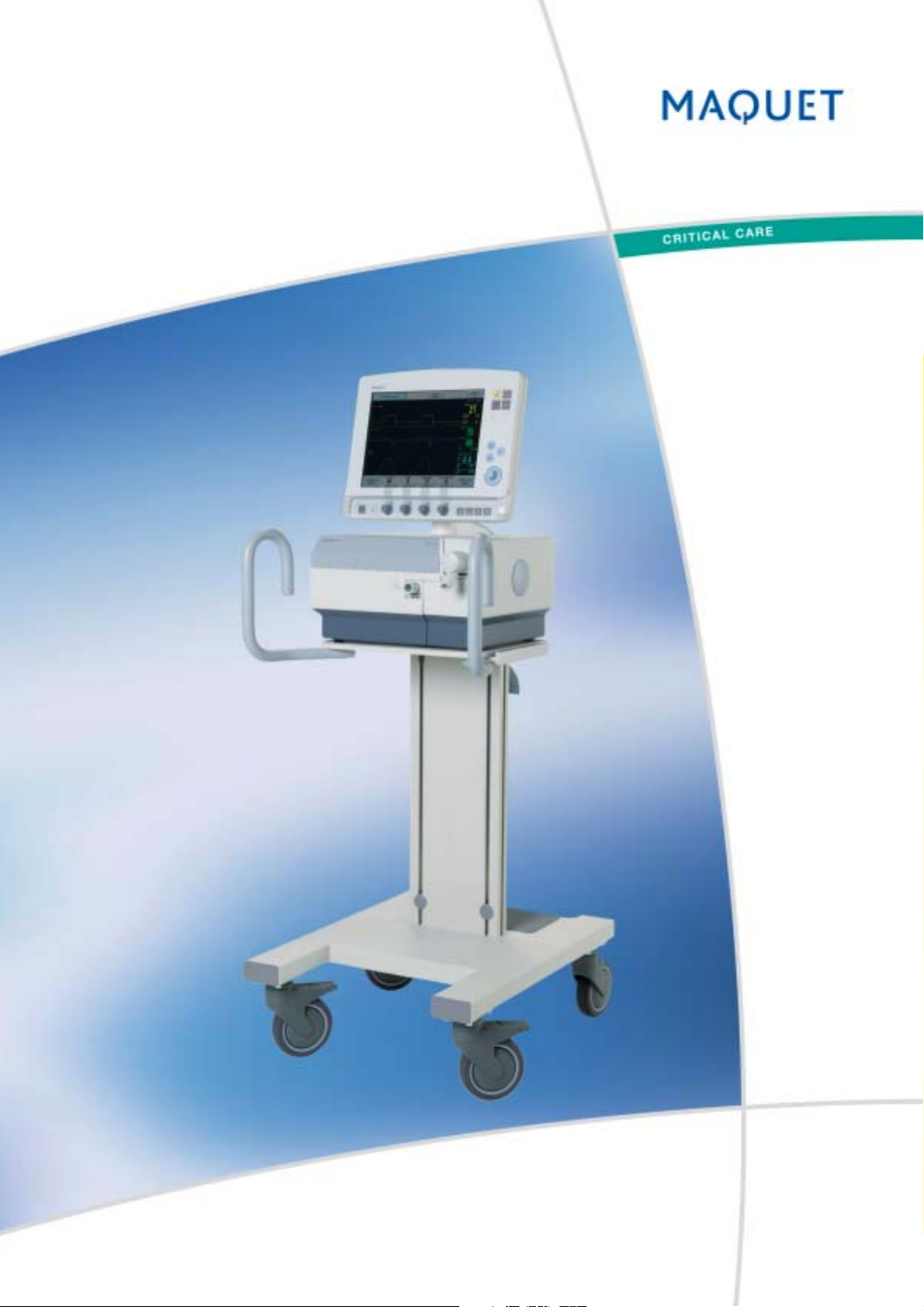
SERVO-s Ventilator System
Service Manual
Page 2
Important SERVO-s Ventilator System
Notes
1 - 2 Service Manual Revision 02
Page 3

SERVO-s Ventilator System Important
Contents
Contents
1. Important .......................................................................
2. Introduction ...................................................................
3. Description of functions ...............................................
4. Disassembling and assembling ...................................
5. Service procedures.......................................................
1
2
3
4
5
6. Troubleshooting ............................................................
7. Preventive maintenance...............................................
8. Index ..............................................................................
9. Service Manual revision history...................................
10. Diagrams .......................................................................
6
7
8
9
10
Revision 02 Service Manual 1 - 3
Page 4
Important SERVO-s Ventilator System
Important
General
• Service documentation for the SERVO-s
1
Ventilator System consists of:
– User's Manual. The User's Manual is an
indispensable complement to the Service
Manual for proper servicing.
– Service Manual
– Installation Instructions
– Spare Parts information
– Documentation for all optional equipment
included in the SERVO-s System is also
available.
• The SERVO-s Ventilator System is referred to as
the SERVO-s throughout this manual.
• There are two serial number labels on the unit:
– One label is attached to the Patient Unit close
to the supply gas inlets. The serial number
stated on this label is the ID number of the
Patient Unit. The serial number is also stored in
the SW memory as the 'System ID'.
– One label is attached to the rear side of the
User Interface close to the On/Off switch. The
serial number stated on this label is the ID
number of the User Interface.
• System version number can be found in the
Status window on the User Interface. Make sure
that the version of the User's Manual corresponds
to the System version.
Symbols used in this manual
• ESD sensitive components. When
handling ESD-sensitive devices,
established procedures must be
observed to prevent damage.
• Special waste. This product contains
electronic and electrical components.
Discard disposable, replaced and
left-over parts in accordance with
appropriate industrial and
environmental standards.
• Recycling. Worn-out batteries must
be recycled or disposed of properly
in accordance with appropriate
industrial and environmental
standards.
• With power supply connected to the
SERVO-s, there are energized
electrical components inside the
unit. Exercise extreme caution if
power supply connected and covers
are removed.
• Technical training. Refers to the
Technical training supplied by
MAQUET.
• Service contract. Refers to the
Service contract supplied by
MAQUET.
Text inside a box is used to highlight important
information.
• In addition to the Important information given
here and in the related documents (e. g. in the
User's manual), always pay attention to applicable
local and national regulations.
• Responsibility for the safe functioning of the
equipment reverts to the owner or user in all
cases in which service or repair has been done
by a non-professional or by persons who are not
employed by or authorized by MAQUET, and
when the equipment is used for other than its
intended purpose.
1 - 4 Service Manual Revision 02
• Only personnel trained and authorized
by MAQUET shall be permitted to
install the SERVO-s. The installation
and handing-over procedures are
described in the 'SERVO-s Ventilator
System – Installation Instructions'.
Functional check
• After any installation, maintenance or service
intervention in the SERVO-s, perform a 'Pre-use
check' according to instructions in the 'SERVO-s
Ventilator System – User's Manual'.
Installation
Page 5
SERVO-s Ventilator System Important
Important
Service
• The SERVO-s must be serviced at
regular intervals by personnel trained
and authorized by MAQUET.
Any maintenance or service must be
noted in a log book provided.
• It is recommended that maintenance
and service is done as a part of a
service contract with MAQUET.
• For functionality enhancement, the latest released
System SW version is always recommended.
• Preventive maintenance must be performed at
least once every year as long as the unit is not
used more than normal. Normal operation is
estimated to correspond to approx. 5.000 hours
of operation. Details are found in this Service
Manual, chapter 'Preventive maintenance'.
• The Battery modules shall be replaced after two
and a half years from their manufacturing date.
• The internal Lithium batteries (on PC 1771 and
PC 1772) shall be replaced every five years.
• Worn-out batteries must be recycled or
disposed of properly in accordance
with appropriate industrial and
environmental standards.
• This product contains electronic and
electrical components. Discard
disposable, replaced and left-over
parts in accordance with appropriate
industrial and environmental standards.
• When working with ESD sensitive
components, always use a grounded
wrist band and a grounded work
surface. Adequate service tools must
always be used.
Hazard notices
• Before disassembling or assembling of the
SERVO-s, make sure that the:
– On/Off switch is set to Off.
– Mains power cable is disconnected.
– Gas supply is disconnected (wall and/or
cylinder).
– Regular cleaning and extended cleaning of the
inspiratory channel are performed. Refer to
instructions in the User's Manual.
• With power supply connected to the
SERVO-s, there are energized
electrical components inside the unit.
All personnel must exercise extreme
caution if fault tracing or adjustments
are performed with power supply connected and
with user interface and patient unit covers
removed.
To the responsible service personnel
• The contents of this document are not binding.
If any significant difference is found between the
product and this document, please contact
MAQUET for further information.
• We reserve the right to modify products without
amending this document or advising the user.
• Only personnel trained and authorized
by MAQUET shall be permitted to
perform installation, service or
maintenance of the SERVO-s. Only
MAQUET genuine spare parts must be
used. PC boards (spare parts) must always be
kept in a package for sensitive electronic
devices. MAQUET will not otherwise assume
responsibility for the materials used, the work
performed or any possible consequences of
same.
• The device complies to standards and requirements as stated in the 'SERVO-s Ventilator
System – User's Manual'.
1
Revision 02 Service Manual 1 - 5
Page 6
Important SERVO-s Ventilator System
Important
Environmental declaration
Purpose
1
This environmental declaration is for a SERVO-s
base unit.
Letters codes within brackets refers to the
Functional Block Diagram in chapter Diagrams.
Components with special environmental
concern
Components listed below shall be disposed of in
accordance with appropriate industrial and
environmental standards.
Printed circuit boards
• PC 1771 Control, including a Lithium battery (C)
• PC 1772 Monitoring, including Lithium battery (M)
• PC 1777 Panel including Backlight Inverter (U)
• PC 1781 Pressure transducer, 2 each (T)
• PC 1784 Expiratory channel (F)
• PC 1785 Expiratory channel connector (E)
• PC 1786 Expiratory channel cassette (E)
• PC 1860 Main back-plane
• PC 1861 Pneumatic back-plane (I)
• PC 1862 DC/DC & Standard connectors (P)
• PC 1863 Power control (P)
Construction materials
The construction materials used in SERVO-s in %
of the total weight.
Metal – total 72.5%
• Aluminium 70%
• Steel, zink, brass 2.5%
Polymeric material – total 8%
• PA (Polyamide)
• POM (Polyoxymethylene)
• SI (Silicone)
• TPE (Thermoplastic elastomer)
• PUR (Polyurethane)
• ABS (Acrylicnitrilebutadienstyrene)
• EPDM (Ethylenepropylenedienemonomer)
• PTFE (Polytetrafluoroethylene)
• FPM (Fluororubber)
• NBR (Nitrilerubber)
• PP (Polypropylene)
• PVC (Polyvinyl chloride)
• PS (Polystyrene)
Electronics – total 19.5%
Other electronics
• TFT assembly including backlight (U)
• Touch screen (glass) (U)
cell, containing caustic lime and lead (Pb) (I)
•O
2
Sensor, containing PC boards (I)
•O
2
• Gas module Air, containing multiple PC boards (I)
• Gas module O
• AC/DC Converter, containing PC boards (P)
• Expiratory cassette (E)
• Expiratory valve coil (E)
• Safety valve pull magnet (I)
• Battery modules Nickel-Metal Hydride (P)
1 - 6 Service Manual Revision 02
, containing multiple PC boards (I)
2
• Battery modules Nickel-Metal Hydride
• Printed circuit boards, cables etc.
Others – very small amounts
• Filter paper of fibre glass
Page 7
SERVO-s Ventilator System Important
Important
Articles of consumption
1. Bacteria filter
2. Filters for the gas modules
3. Filter for the inspiration pressure transducer
4. Filter for the O
5. Nozzle units for the gas modules
6. Battery modules
7. Lithium batteries
8. Expiratory cassette
9. Expiratory cassette membrane
cell (if applicable)
10. O
2
11. Backlight lamps.
Item 1: Consumption approximately 250 pcs/year.
Items 2 – 5: Changed approx. every 5.000 hours.
Items 6: Changed approx. every 12.500 hours.
Items 7: Changed approx. every 25.000 hours.
Items 8 – 11: Changed when needed.
cell (if applicable)
2
Noise level
Less than 50 dBA.
1
Packing materials
The amounts of packing materials will vary
depending on customer adaptation.
Materials for packing:
• Loading pallet. Fulfils the USA requirements
7 CFR 319.40 May 25’th 1995.
• Corrugated cardboard
• Shock-absorbing material of expanded polyethylene, EPE, or expanded polypropylene, EPP.
Product End-of-Life
For scrapping information, refer to the document
'SERVO-s Ventilator System – Product End-of-Life
Disassembly Instructions.
Power consumption
The power consumption depends on the operating
mode and whether the internal batteries are being
fast or trickle charged.
Mode Fast charging Trickle charging
In operation 70 W 38 W
Standby 65 W 33 W
Off 35 W 6 W
Revision 02 Service Manual 1 - 7
Page 8
Important SERVO-s Ventilator System
Notes
1
1 - 8 Service Manual Revision 02
Page 9
SERVO-s Ventilator System Introduction
Only personnel trained and authorized
by MAQUET shall be permitted to
perform installation, service or
maintenance of the SERVO-s.
Make sure to prepare the SERVO-s properly
before disassembling and assembling. Refer to
section 'Hazard notices' in chapter 'Important'.
Any service or maintenance must be noted in a
log book.
After any installation, maintenance or service
intervention in the SERVO-s, perform a 'Pre-use
check'. Refer to the 'SERVO-s Ventilator System –
User's Manual' for details.
This product contains electronic and
electrical components. Discard
disposable, replaced and left-over parts
in accordance with appropriate industrial
and environmental standards.
2. Introduction
Main units .......................................................... 2 - 2
User Interface ................................................. 2 - 4
Patient Unit ..................................................... 2 - 6
SERVO-s software structure ............................. 2 - 9
General ........................................................... 2 - 9
Breathing ........................................................ 2 - 9
Monitoring ...................................................... 2 - 9
Panel ............................................................... 2 - 9
System ID ....................................................... 2 - 9
2
Revision 02 Service Manual 2 - 1
Page 10
Introduction SERVO-s Ventilator System
Main units
The SERVO-s is configured for adults and pediatrics
with a number of ventilation modes suitable for these
patient categories.
The SERVO-s can be divided into the following main
units:
• User Interface. The User Interface contains all
2
controls used to set the ventilation and monitoring
parameters. Ventilation parameters as well as other
important information are shown on the User
Interface display.
• Patient Unit. The Patient Unit contains pneumatics
and electronics for gas supply to the patient.
Power supply and battery back-up is also
contained in the Patient Unit.
The Control cable connects the User Interface and
the Patient Unit.
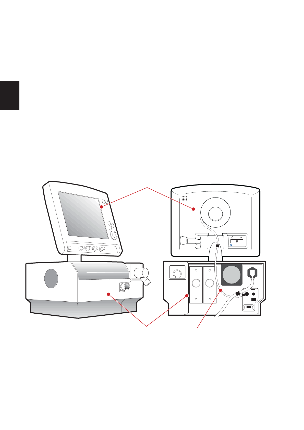
ServoS-9000
User Interface
Patient Unit
Control cable
2 - 2 Service Manual Revision 02
Page 11

SERVO-s Ventilator System Introduction
A number of optional equipment can be added to the
SERVO-s Ventilator System. For further information,
refer to the documents listed below.
Mobile cart SERVO-s
• SERVO-s – User's manual
• Mobile cart, SERVO-s – Installation Instructions
Shelf base SERVO-s
• SERVO-s – User's Manual
• Shelf base, SERVO-s – Installation Instructions
Support Arm 176/177
• SERVO-s – User's Manual
• Support Arm 176/177 – Installation Instructions
Gas cylinder restrainer SERVO-s
• SERVO-s – User's manual
• Gas cylinder restrainer, SERVO-s – Installation
Instructions
Aeroneb Pro
• Aeroneb Pro – Instruction Manual
• Aeroneb Pro – Installation Instructions
User Interface panel cover
• SERVO-s – User's Manual
• User Interface panel cover – Installation
Instructions
2
Loudspeaker booster kit
• Loudspeaker booster kit – Installation Instructions
Isolation shield with drip guard
• Isolation shield with drip guard – Installation
Instructions
Compressor Mini
• SERVO-s – User's Manual
• Compressor Mini – Operating Manual
• Compressor Mini – Service Manual
• Compressor Mini – Installation Instructions
Alarm output connector
• SERVO-s – User's Manual
• Alarm output connector – Reference Manual
Humidifier, Humidifier Holder and Humidifier
Holder for rail
• SERVO-s – User's Manual
• Humidifier – Operating Manual
• Humidifier Holder – Installation Instructions
Waterbag pole
• Instructions mounted on the pole.
Revision 02 Service Manual 2 - 3
Page 12
Introduction SERVO-s Ventilator System
2
ServoS-9002
User Interface
Items accessible from the outside of the User
Interface are shown in the above illustration.
1. Display with touch screen.
2. Fixed keys for immediate access to special
windows.
3. Main rotary dial.
4. Special function keys.
5. Direct access knobs.
6. Mains indicator (green).
7. Standby indicator (yellow).
8. Start/Stop (Standby) ventilation key.
9. Luminescence detector, adjusts display
brightness automatically. On User Interface of
Type 1, the detector is placed in the upper left
corner. On User Interface of Type 2, the detector
is placed above the Fixed keys in the upper right
corner.
10. Loudspeaker grid.
11. Cable reel.
12. PC card slot with slot cover.
13. Control cable between User Interface and Patient
Unit.
14. Service connector, for PC.
15. On/Off switch and switch cover, version
discontinued in production Q2 2007.
16. On/Off switch and switch cover, version
introduced in production Q2 2007.
17. Locking arm, tilting.
18. Serial number label. The serial number stated on
this label is the ID number of the User Interface.
This serial number must always be refered to
when ordering service, spare parts, etc for the
User Interface.
For further information regarding operation of the
User Interface, refer to the User's manual.
2 - 4 Service Manual Revision 02
Page 13
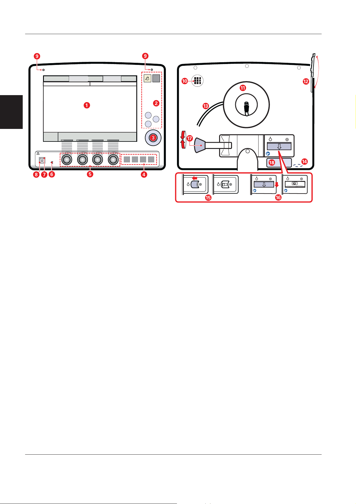
SERVO-s Ventilator System Introduction
=<
9
H
;
2
ServoS-9004
6
ServoS-9003
?@
When the front panel section is removed from the
rear cover, the following parts are accessible:
1. Touch screen incl. frame.
2. TFT Display.
3. Backlight lamp.
4. PC board Backlight inverter.
5. PC 1777 Panel including PC Card slot.
6. Loudspeaker.
7. Main rotary dial (rotary encoder with switch).
8. Direct access controls (rotary encoder).
The illustration above shows User Interface of Type 2.
Revision 02 Service Manual 2 - 5
Page 14
Introduction SERVO-s Ventilator System
2
ServoS-9005
Patient Unit
Items accessible from the outside of the Patient Unit
are shown in the illustration above. All labels
attached to the rear side of the Patient Unit are
described in the User's Manual.
1. Expiratory outlet.
2. Gas module for Air.
3. Gas module for O
4. Internal fan with filter.
5. Control cable connector.
6. Serial port for data communication (RS 232).
7. Alarm output connector (optional).
.
2
8. Connector for external +12V DC power supply.
9. Fuse F1 for external +12V DC power supply.
10. Mains supply connector incl. fuses F11 and F12.
11. Equipotentiality terminal.
12. Inspiratory outlet.
13. Expiratory inlet.
14. Serial number label. The serial number stated on
this label is the ID number of the Patient Unit.
The serial number is also stored in the SW
memory as the 'System ID'. This serial number
must always be refered to when ordering service,
spare parts, software updates/upgrades, etc.
2 - 6 Service Manual Revision 02
Page 15
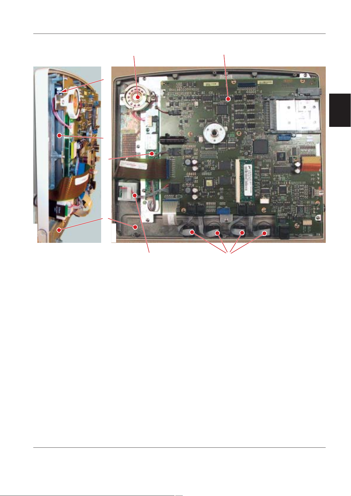
SERVO-s Ventilator System Introduction
When the Patient Unit main cover is opened, the
following parts are accessible:
1. The inner part of the two gas modules including
their nozzle units.
2. Connector muff.
3. Inspiratory pressure transducer tube, incl.
bacteria filter, to connect the inspiratory pressure
transducer.
4. Inspiratory pipe with housings for the O
cell and for the safety valve.
cell incl. bacteria filter.
5. O
2
Sensor. Alternative to the O2 cell for oxygen
6. O
2
concentration measurement.
Sensor/
2
7. PC 1861 Pneumatic back-plane (covered by the
metal plate). The gas modules, the O
and the safety valve pull magnet are connected
Sensor/cell
2
to PC 1861.
2
ServoS-9012
ServoS-9013
?< ;H69
=
ServoS-9108
@"
When the Patient Unit main cover is removed, the
following parts are accessible:
8. AC/DC Converter.
9. PC 1772 Monitoring.
10. PC 1771 Control.
11. PC 1863 Power control.
12. PC 1862 DC/DC & Standard connectors.
13. PC 1860 Main back-plane. The PC boards listed
above are connected to PC 1860 Main backplane.
14. Battery modules.
15. Internal fan.
A!.
Revision 02 Service Manual 2 - 7
Page 16
Introduction SERVO-s Ventilator System
2
ServoS-9014
ServoS-9015
'
%
#
&%
When the Patient Unit side cover is removed, the
following parts are accessible:
16. PC 1784 Expiratory channel with the two
connected PC 1781 Inspiratory and Expiratory
Pressure Transducers.
17. PC 1785 Expiratory channel connector.
18. Expiratory valve coil.
The expiratory cassette (19) is a complete unit. It
contains the following parts:
• Expiratory inlet with moisture trap.
• PC 1786 Expiratory channel cassette.
• Ultrasonic flowmeter.
• Heating foil to keep a stable temperature in the
expiratory gas.
• Pressure transducer connection, incl. bacteria
filter, to connect the expiratory pressure
transducer.
• Expiratory valve incl. valve membrane.
• Expiratory one-way valve.
The expiratory valve coil, mounted under the
expiratory cassette compartment, controls the valve
membrane in the cassette.
PC 1786 Expiratory channel cassette inside the
expiratory cassette is electrically connected to
PC 1784 Expiratory channel via PC 1785 Expiratory
channel connector (17).
ServoS-9016
2 - 8 Service Manual Revision 02
Page 17
SERVO-s Ventilator System Introduction
EXP.
INLET
SERVO-s software structure
General
The SERVO-s software installed in the ventilator will
contain all available system functionality. The software is separated into different subsystems and
stored on some of the PC boards. The separation of
the software is handled by the installation program.
The SERVO-s software is divided into the following
software subsystems:
• Breathing
• Monitoring
• Panel
• System ID
PC 1777
PANEL SW
Breathing
The Breathing SW controls the delivery of gases to
the patient. This subsystem is responsible for the
breathing system, that is:
• Ventilation control and regulation
• Inspiratory channel
• Expiratory channel
The Breathing SW is stored on PC 1771 Control and
PC 1784 Expiratory Channel. The software must be
re-installed if PC 1771 or PC 1784 is replaced. New
software can be installed via a SW Service Release.
The Breathing SW is executed by microprocessors
on PC 1771 and PC 1784.
Monitoring
The Monitoring SW controls all monitoring and alarm
functions in the system, including trends of measured
values (trend data not available in SERVO-s v1.0).
Events, such as alarms and change of settings will
also be logged.
The Monitoring SW is stored on PC 1772 Monitoring.
The software must be re-installed if PC 1772 is
replaced. SW related to Monitoring is also stored in
Sensor. New software can be installed via a
the O
2
SW Service Release.
The Monitoring SW is executed by the
microprocessor on PC 1772.
2
Panel
AC/DC CONVERTER
MONITORING SW
BREATHING SW
PC 1863
PC 1862
BATTERY
BATTERY
ServoS-9017
PC 1772
PC 1771
INSP.
OUTLET
SYSTEM ID SW
PC 1861
PC 1860
BREATHING SW
EXP.
INLET
INLET
PC 1785
PC 1781
PC 1781
PC 1784
The Panel SW controls all user interaction, as well as
software updating to all subsystems via the PC Card
interface.
The Panel SW is stored on PC 1777 Panel. The
software must be re-installed if PC 1777 is replaced.
New software can be installed via a SW Service
Release.
The Panel SW is executed by the microprocessor on
PC 1777.
EXP.
System ID
The System ID SW is a configuration file, stored on
PC 1860 Main Back-Plane, that is unique for each
ventilator. The System ID SW will enable the
functions selected for this ventilator.
To change the functions of the ventilator, a new
System ID SW can be installed via an Option Upgrade.
When replacing PC 1860 Main Back-Plane, a spare
Revision 02 Service Manual 2 - 9
part that is factory programmed for the concerned
ventilator must be used.
Page 18
Introduction SERVO-s Ventilator System
Notes
2
2 - 10 Service Manual Revision 02
Page 19
SERVO-s Ventilator System Description of functions
Only personnel trained and authorized
by MAQUET shall be permitted to
perform installation, service or
maintenance of the SERVO-s.
Make sure to prepare the SERVO-s properly
before disassembling and assembling. Refer to
section 'Hazard notices' in chapter 'Important'.
Any service or maintenance must be noted in a
log book.
After any installation, maintenance or service
intervention in the SERVO-s, perform a 'Pre-use
check'. Refer to the 'SERVO-s Ventilator System –
User's Manual' for details.
This product contains electronic and
electrical components. Discard
disposable, replaced and left-over parts
in accordance with appropriate industrial
and environmental standards.
3.Description of functions
About this chapter ............................................. 3 - 2
Memory types used in the SERVO-s ................ 3 - 2
User Interface .................................................... 3 - 2
User Interface controls ................................... 3 - 2
PC 1777 Panel................................................ 3 - 2
Loudspeaker................................................... 3 - 2
Backlight Inverter ........................................... 3 - 3
Touch screen including frame ....................... 3 - 3
TFT Display with Backlight ............................ 3 - 3
Patient unit......................................................... 3 - 3
Inspiratory section .......................................... 3 - 3
Expiratory section .......................................... 3 - 6
PC 1860 Main back-plane ............................. 3 - 8
Pressure transducers ..................................... 3 - 8
PC 1771 Control ............................................. 3 - 8
PC 1772 Monitoring ....................................... 3 - 9
3
PC 1784 Expiratory Channel.......................... 3 - 9
Power supply ..................................................... 3 - 9
Control cable ..................................................... 3 - 11
Optional equipment ........................................... 3 - 12
Alarm output connector ................................. 3 - 12
Loudspeaker booster kit ................................ 3 - 12
Isolation shield with drip guard ...................... 3 - 12
Revision 02 Service Manual 3 - 1
Page 20

Description of functions SERVO-s Ventilator System
About this chapter
This text refers to the Functional Main Blocks
diagram in chapter 'Diagrams'.
Memory types used in the SERVO-s
There are four different types of memories used in
the SERVO-s:
• Flash memory. For System SW storage. Present on
PC 1771, PC 1772, PC 1777, PC 1784 and in the
Sensor. The System SW can be re-installed/
O
2
updated using a SW Service Release.
• RAM. For temporary storage of software and data.
3
Present on PC 1771, PC 1772 and PC 1777.
• Non-volatile memory. RAM with battery backup.
For settings, trends and logs. Present on PC 1771
and PC 1772.
• EEPROM. For PC board information, configuration,
calibration data, etc. Present on almost all PC
boards and in the O
EEPROM is emulated by the Flash memory.
cell. In the O2 Sensor, an
2
User Interface
Functional Main Blocks diagram marking: 'U'.
There are two different versions of the User Interface.
In this manual, they are described as:
• Type 1 – Up to User Interface S/N 201200
(SERVO-s S/N 02000).
• Type 2 – User Interface S/N 201201
(SERVO-s S/N 02001) and higher.
There is no difference in the clinical operation
between the two versions, but the electronics inside
the User Interface differs. As a consequence, some
of the spare parts are not compatible between the
two versions. Further information can be found
below and also in the SERVO-s Spare Parts List.
PC 1777 Panel
Some features included on PC 1777 Panel are:
• SIMM (Single In-line Memory Module) mounted on
its connector P77. Memory type: SDRAM
• PC Card Slot intended for connection/insert of a
PC Card. PC Cards are used to:
– Download software into the different flash
memories situated on PC-boards marked μP and
into the EEPROM on PC 1860 Main back-plane.
– Transfer patient and system data for further
transfer to a computer.
– Service purpose.
• Microprocessor μP on this board includes control
of the functions of the User Interface.
• ID-PROM: The ID information can be read by the
SERVO-s.
• On/Off switch: Switch to Power up or Power down
the SERVO-s . Refer to section 'Power supply'.
A new design of the On/Off switch and the switch
cover was introduced Q2 2007. Refer to chapter
'Disassembling and assembling' for further
information.
• Connection for PC (P86): Ethernet port intended for
test and service purpose. Connected via a service
cable. For future options.
• Microphone used to monitor sounds from the
Loudspeaker.
There are two different versions of PC 1777, Type 1
and Type 2. The PC 1777 spare part is not
compatible between the two versions.
For PC 1777 of Type 2, System SW version V2.00.04
or higher is required.
Note: The System SW must be re-installed if PC 1777
is replaced.
Loudspeaker
For generation of sound, e.g. alarm. Connected to
User Interface controls
Setting of different parameter input values is made
with the help of the following different interface
devices:
• Main Rotary Dial (rotary encoder with switch).
• Direct Access Knob, 4 each (rotary encoders).
• Membrane buttons. Integrated parts of the Touch
screen assembly.
• Touch screen.
3 - 2 Service Manual Revision 02
P72 on PC 1777 Panel.
The loudspeaker generates different tones with
individual sound volumes. At startup and during Preuse check the function of the loudspeaker is
monitored by the microphone on PC 1777. During
operation it is continuously monitored through
current sensing.
With the optional accessory 'Loudspeaker booster
kit', the alarm sound is amplified. Refer to section
Optional equipment.
Page 21
SERVO-s Ventilator System Description of functions
Backlight Inverter
PC board with driving stage for backlight (lamps)
mounted behind the TFT Display. The supply voltage
delivered by the Backlight Inverter is 660 V.
The Backlight Inverter is connected to P73 on
PC 1777 Panel.
There are two different versions of the Backlight
Inverter, Type 1 and Type 2. The Backlight Inverter
spare part is not compatible between the two
versions.
Touch screen including frame
The Touch screen implies the touch function of the
front panel screen and is interactive with information
displayed on the TFT Display. The front panel frame
with the touch screen, membrane buttons and DIM
sensor forms the assembly Touch screen incl. frame
and must be handled as one complete part. The DIM
sensor measures the ambient light and the screen
brightness is automatically adjusted.
There are two different versions of the Touch screen
incl. frame, Type 1 and Type 2. The Touch screen
incl. frame spare part is not compatible between the
two versions.
Patient unit
Inspiratory section
Functional Main Blocks diagram marking: 'I'.
The main block Inspiratory Section conveys the
breathing gas from its gas inlets for Air and O
to the patient breathing system. It comprises the
following main functions:
• Gas Modules – Air and O
.
2
• Connector Muff.
• Inspiratory Pipe.
Sensor/cell.
•O
2
• Inspiratory Pressure Tube.
• Safety Valve including pull magnet.
• Inspiratory Outlet.
• PC 1861 Pneumatic Back-Plane.
Gas modules – Air and O
2
The Air and O2 Gas Modules regulates the inspiratory
gas flow and gas mixture.
supply
2
3
TFT Display with Backlight
The TFT Display is a Thin Film Transistor Screen for
color display of picture- and alphanumeric data.
There are two different versions of the TFT Display:
• Type 1 with Backlight consisting of two separate
fluorescent lamps mounted behind the TFT Screen.
• Type 2 with Backlight consists of one fluorescent
lamp mounted behind the TFT Screen.
The TFT Display spare part is not compatible
between the two versions.
The Backlight lamps are driven from the Backlight
Inverter. Estimated lifetime (with acceptable
brightness level) for the lamps is 30.000 hours.
Using the Field Service System (FSS), a time meter
for the lamps can be shown. The time meter must be
reset after replacement of the lamps.
ServoS-9018
1. Filter
2. Inspiratory valve temperature sensor
3. Supply pressure transducer
4. Flow transducer (Delta pressure transducer and net)
5. Nozzle unit with valve diaphragm
6. Inspiratory solenoid
The Gas Modules are factory calibrated. Each Gas
Module
must not be disassembled further than
described in chapter 'Preventive maintenance'.
Revision 02 Service Manual 3 - 3
Page 22

Description of functions SERVO-s Ventilator System
Gas inlet
Gas supply is connected to the ventilators gas inlet
nipples. The design of the gas inlet nipples vary
according to the standard chosen.
Gas is to be connected from hospital central gas
supply or from gas cylinders. The Air supply may be
connected from a compressor for medical air.
Filter
The Filter protects the ventilator from particles in the
gas delivered to the Gas Modules. The filter must be
replaced during the 'Preventive maintenance'.
The filter housing and the filter cover are provided
3
with matching guide pins. These guide pins prevent
mounting of the filter cover (with gas inlet nipple) on
the wrong module.
A non-return valve for the gas inlet is located in the
filter cover. This valve will suppress short pressure
drops in the gas supply.
The non-return valve is also designed to slowly
evacuate compressed gas from the module, if the
gas supply to the module is disconnected.
Inspiratory valve temperature sensor
The temperature of the supplied gas is measured by
the Inspiratory Valve Temperature Sensor. This
sensor is situated in the gas flow.
The output signal from this sensor is used to
compensate for the gas density variations due to
temperature.
The complete plastic nozzle unit must be replaced
during the 'Preventive maintenance'.
After replacement, allow the diaphragm to settle
during approx. 10 minutes before gas pressure is
connected to the Gas Module.
Inspiratory solenoid
The gas flow through the Gas Module is regulated by
the Inspiratory Solenoid via the Nozzle Unit.
The current supplied to the solenoid is regulated so
that the gas module will deliver a gas flow according
to the settings on the User Interface.
Gas module key
The Gas Modules are provided with a mechanical
key to prevent that the module is mounted in the
wrong slot.
The key consists of a plastic guide mounted underneath the module and a corresponding guide
mounted in the patient unit.
ID PROM
Each Gas Module is provided with an ID-PROM. The
ID information can be read by the SERVO-s.
Connector muff
The Connector Muff connects the Gas Module
outlets to the Inspiratory Pipe inlet.
Supply pressure transducer
The pressure of the supplied gas is measured by the
Supply Pressure Transducer.
The output signal from this transducer is amplified. It
is then used to calculate the absolute pressure of the
gas to compensate for gas density variations due to
pressure.
Inspiratory pipe
The Inspiratory Pipe leads the gas from the
Connector Muff to the Inspiratory Outlet.
The Inspiratory Pipe comprises:
• Housing for the O
locking lever for the O
Sensor as well as housing and
2
cell with its bacteria filter.
2
• Housing for the Safety Valve.
Flow transducer
The gas flows through a net (resistance) which
causes a pressure drop. The pressure is measured
on both sides of this net and the differential pressure
value is then amplified.
Nozzle unit
The plastic Nozzle Unit contains a valve diaphragm.
The valve diaphragm, controlled by the Inspiratory
• Connection for measurement of inspiratory
pressure.
The pipe is provided with internal flanges with the
purpose to improve mixing of O
The O
Inspiratory pipe. The O
pipe are equipped with a mechanical key to prevent
that the O
Inspiratory pipe. The O
versions of the Inspiratory pipe.
Sensor requires a changed design of the
2
Sensor is mounted on wrong type of
2
Sensor and the Inspiratory
2
cell can be used on both
2
and Air.
2
Solenoid, regulates the gas flow through the Gas
Module.
3 - 4 Service Manual Revision 02
Page 23
SERVO-s Ventilator System Description of functions
O
cell
2
The O
Inspiratory Pipe and is protected by a bacteria filter.
cell is mounted in a housing on the
2
Sensor
O
2
The O
Inspiratory pipe as an alternative to the O
Sensor is mounted in a housing on the
2
cell.
2
Maintenance including exchange of bacteria filter
according to the User´s manual. The bacteria filter
must also be replaced during the 'Preventive
maintenance'.
The O
the partial pressure of oxygen inside the Inspiratory
pipe. At constant ambient pressure this output is
proportional to the O
In each O
constant level usually within 10–17 mV in normal air
and at standard barometric pressure during the life
time of the cell.
The life time of the cell is affected by the O
concentration. With a concentration (at the cell) in
% and expected cell life time in hours the following
applies at 25
The O
Pre-use check is performed (if O
ventilator).
If the ventilator has continually been in use for a long
time, the measured O
to normal degradation of the O
a nuisance alarm. For further information, refer to the
User's Manual.
Note: Pre-use check is recommended to use in order
to calibrate the O
An ID PROM is integrated into each O
information and remaining lifetime can be read by the
SERVO-s.
cell gives an output voltage proportional to
2
concentration in percent.
2
cell, the output signal will stay at a fairly
2
2
o
C (77oF):
Conc. x Expected cell life = 500 000% hours.
O
2
cell is automatically calibrated each time a
2
concentration may drop due
2
cell.
2
is connected to the
2
cell. This will activate
2
cell. Its ID
2
SVX9110
The O2 Sensor is a measuring device for the inspired
oxygen concentration, using ultrasound technique
with two ultrasonic transducers/receivers.
The sound velocity in oxygen is lower than in air.
By measuring the sound velocity in a binary gas mix,
where the two gases are known (air and oxygen),
the ratio between the gases can be calculated,
concentration.
i.e. O
2
The technique for the O
in the expiratory cassette, with one transducer
Sensor is similar to the one
2
transmitting an ultrasonic pulse through the gas and
the other one receiving the pulse. The measured time
difference between the transmission and the
reception of the pulse is used for calculation of the
sound velocity, which is then used for calculation of
concentration.
the O
2
A temperature sensor inside the O
the gas temperature and this measurement is used
when calculating the O
Each O
information can be read by the SERVO-s System.
Sensor is provided with an ID-PROM. The ID
2
concentration.
2
Sensor measures
2
Inspiratory pressure tube
The Inspiratory Pressure Tube connects the Inspiratory Pipe with the Inspiratory Pressure Transducer.
A bacteria filter protects the pressure transducer on
PC 1781 Pressure Transducer from contamination.
Maintenance including exchange of bacteria filter
according to User´s manual. The bacteria filter must
also be replaced during the 'Preventive maintenance'.
3
Revision 02 Service Manual 3 - 5
Page 24
Description of functions SERVO-s Ventilator System
Safety valve
The movable axis of the Safety Valve Pull Magnet
controls the opening and closing of the safety valve
membrane in the Inspiratory Pipe. The pull magnet is
electrically activated (closed) from the main block
Expiratory Channel.
When the Safety Valve is not activated, the weight of
the pull magnet axis, in combination with the design
3
of the valve membrane, pushes the pull magnet axis
downwards. This actuates the Safety Valve to be
opened and the inspiratory gas is let out from the
Inspiratory Pipe via the Safety Outlet thus enabling a
decrease in the inspiratory pressure. The Safety
Outlet is covered by a plastic grid.
This is normal safety (pop-off) function.
The opening conditions for the safety valve are:
• The ventilator is switched Off or to Standby.
• The pressure inside the inspiratory pipe is
5 cm H
Alarm limit. This condition is controlled by the
O above the preset Upper Pressure
2
Monitoring subsystem.
• The pressure inside the inspiratory pipe is
7 cm H
Alarm limit. This condition is controlled by the
O above the preset Upper Pressure
2
Breathing subsystem.
• The pressure inside the inspiratory pipe is above
117 ±7 cm H
this situation will normally not occur.
O. This is an extra safety function and
2
• The safety valve will also be opened by some other
alarms, e. g. the Out of gas-alarm.
During startup, the pull magnet is electrically
activated so that the pull magnet axis is pushed up
(with a clicking sound). This is the normal operational
position of the pull magnet; the Safety Valve is
normally kept closed.
The safety valve opening pressure is calibrated to
117 ±3 cm H
O during each Pre-use check.
2
Inspiratory outlet
22 mm / 15 mm tube connector for the inspiratory
tube of the patient breathing system.
PC 1861 Pneumatic back-plane
Interconnecting board including connectors for the
Gas Modules as well as cable connectors for the
Safety Valve and the O
Sensor/cell.
2
Expiratory section
Functional Main Blocks diagram marking: 'E'.
The main block Expiratory Section conveys the
breathing gas from the patient breathing system to
the Expiratory Outlet. It comprises:
• Measurement of expiratory flow
• Connection for measurement of expiratory
pressure.
• Controlling element for the regulation of expiratory
pressure.
Expiratory cassette
The expiratory gas conveying parts and PC 1786
Expiratory Channel Cassette are integrated into one
part – the Expiratory Cassette – which can be easily
removed for cleaning or exchange. See SERVO-s
Ventilator System – User’s manual.
The expiratory cassette can be interchanged
between different SERVO-s systems. A Pre-use
check is always required after exchanging the
expiratory cassette.
A re-designed version of the Expiratory cassette was
introduced during Q1 2005 starting with cassette S/N
35000. The new cassette has a larger pressure
transducer channel and this will significantly reduce
the drying time needed before use.
PC 1786
Ultrasonic
transducer
Inlet
ServoS-9019
Heating
foil
Expiratory
channel cassette
Bacteria
filter
Expiratory inlet
22 mm / 10 mm tube connector for the expiratory
tube of the patient breathing system. The inlet is
designed to make condensed water drip out and
allow use of a water trap for such water to be
collected. Expiratory inlet bacteria filter can be
connected to protect the cassette from
contamination.
Ultrasonic
transducer
Expiratory pressure
tube connector
Outlet
3 - 6 Service Manual Revision 02
Page 25
SERVO-s Ventilator System Description of functions
Heating foil
An electrical Heating Foil applied on the outside of
the expiratory pipe where the Ultrasonic Flowmeter
is situated. The purpose of the Heating Foil to reduce
condensation and maintain a stable temperature in
the expiratory gas.
Ultrasonic flowmeter
The Ultrasonic Flowmeter is a measuring device for
the expiratory gas flow, using ultrasound technique
with two ultrasonic transducers/receivers.
The measuring process is controlled from the main
block PC 1784 Expiratory Channel.
Bacteria filter and expiratory pressure tube
Via a Bacteria Filter inside the cassette, the
Expiratory Pressure Tube connects the cassette to
the Expiratory Pressure Transducer. The filter and
the connector are integrated parts of the cassette.
The filter protects the transducer on PC 1781
Pressure Transducer from contamination.
Expiratory valve
The Expiratory Valve consists of a membrane in the
cassette that is operated by the axis of the
Expiratory Valve Coil. The valve is fully open as long
as no power is supplied to the coil.
Operating capacity for the membrane is estimated to
10.000.000 breathing cycles. When this limit is
passed or if the membrane for some reason has
become defective, it must be replaced. Refer to
instructions in chapter 'Disassembling and
assembling'.
Remaining operating capacity (in %) for the
membrane can be shown in the Status window.
Select Status / Exp. cassette to check 'Remaining
membrane capacity'. The operating capacity meter
must be reset after replacement of the membrane.
3
SVX9018X
The left hand side transducer is sending out
ultrasonic sound that is reflected against the inner
wall of the expiratory channel. The ultrasonic sound
is received by the right hand side transducer now
acting as a receiver. The time from sending to
receiving ultrasonic sound in downstream expiratory
gas flow is measured.
Then the right hand side transducer (earlier receiving)
is sending out ultrasonic sound upstream the
expiratory gas flow. The ultrasonic sound is received
by the left hand side transducer now acting as a
receiver. The time from sending to receiving
ultrasonic sound in upstream expiratory gas flow is
measured.
The time difference between the downstream and
the upstream time measurements provides flow
information.
A temperature sensor inside the cassette measures
the expiratory gas temperature. This temperature
measurement is also used when calculating the
expiratory flow.
Expiratory valve coil
The movable axis of the Expiratory Valve Coil
controls the opening of the Expiratory Valve by
pushing the valve membrane into desired position.
The power supply to the coil is regulated so that the
remaining pressure in the patient system, towards
the end of the expiration time, is kept on the PEEP
level according to front panel setting.
Expiratory outlet with expiratory one-way valve
The gas from the patient system leaves the ventilator
via this Expiratory Outlet. Backflow via the cassette
is prevented by the Expiratory One-Way Valve. Its
rubber membrane and valve seat are integrated parts
of the Expiratory Outlet.
PC 1786 Expiratory channel cassette
The PC 1786 Expiratory Channel Cassette is a
connection board, integrated into the Expiratory
Cassette, for the Ultrasonic Flowmeter and for the
Heating Foil. It connects to PC 1785 mounted in the
expiratory cassette compartment.
Includes an ID PROM. The ID information can be
read by the SERVO-s.
Revision 02 Service Manual 3 - 7
Page 26

Description of functions SERVO-s Ventilator System
PC 1785 Expiratory channel connector
The PC 1785 Expiratory Channel Connector is a
connector board including signal filters that is
mounted in the expiratory cassette compartment.
It connects to PC 1786 mounted in the Expiratory
Cassette when the cassette is docked to the
expiratory cassette compartment.
PC 1860 Main back-plane
Interconnection board for the PC boards in the leftside part of the patient unit.
The ventilators System ID (Serial No.), configuration,
operating time, etc, is stored in an EEPROM on PC
3
1860. Thus, when replacing PC 1860, a spare part
that is factory programmed for the concerned
ventilator must be used.
As the preventive maintenance time stamp will be
reset when replacing PC 1860, a new time stamp
must be set via the Biomed menu. In order to make
this new time stamp correct, the preventive maintenance must be performed. Refer to chapter 'Preventive maintenance'.
Pressure transducers
Functional Main Blocks diagram marking: 'T'.
PC 1781 Inspiratory pressure transducer
The pressure, conveyed via the pressure tube
connected to this block, is led to and measured by
its differential pressure transducer. With differential
reference to the ambient pressure, the output signal
is proportional to the measured pressure thus giving
a linear measurement in the range -40 cm H
+160 cm H
Technical limitation: Pressure exceeding ±400 cm
O must be avoided.
H
2
Includes an ID PROM. The ID information can be
read by the SERVO-s.
PC 1781 Expiratory pressure transducer
Function identical to PC 1781 Inspiratory Pressure
Transducer.
O.
2
O to
2
PC 1771 Control
Functional Main Blocks diagram marking: 'C'.
The main block Control comprises microprocessor
control of Breathing pattern for all different
ventilation modes.
Electronics including microprocessor (μP) control to
achieve:
1. Regulation of Inspiratory flow which is used during
inspiration time in Volume Control (VC) mode.
2. Regulation of Inspiratory pressure which can be
used during inspiration time in any mode.
3. Regulation of a constant Inspiratory flow which is
used during expiration time in all modes.
4. Respiratory timing pattern including frequency as
well as distribution of the duration for Inspiration
time, Pause time and Expiration time according
to front panel settings.
5. Regulation of Inspiratory flow during inspiration
time. The desired total Inspiratory flow value
according to front panel settings is used to
generate the flow reference signals Insp Flow Ref
1 and Insp Flow Ref 2. The level relation between
these two flow reference signals depends on the
desired O
setting. Insp Flow Ref 1 and Insp Flow Ref 2 are
used for the control of its respective Gas Module
(Air and O
Regulation of a constant Inspiratory flow during
expiration time: The desired constant Inspiratory flow
value is the default Bias flow value (see User’s
manual).
This desired constant Inspiratory flow value is used
to generate the flow reference signals Insp Flow Ref
1 and Insp Flow Ref 2 with the same relation and
same handling as described above under 'Regulation
of Inspiratory flow..…' except this occurs during
expiration time.
Includes an ID PROM. The ID information can be
read by the SERVO-s.
Note: The System SW must be re-installed if
PC 1771 is replaced.
A lithium battery on PC 1771 power supplies the
internal memory on the PC board. If the battery on
PC 1771 is disconnected or if the battery voltage is
too low, user default configurations made via the
Field Service System (FSS) and Pre-use check
results including transducer calibrations will be
erased. The lithium batteries must be replaced after
5 years.
concentration according to front panel
2
).
2
3 - 8 Service Manual Revision 02
Page 27

SERVO-s Ventilator System Description of functions
PC 1772 Monitoring
Functional Main Blocks diagram marking: 'M'.
The main block Monitoring comprises microprocessor
(μP) calculation of parameters and monitoring of
alarm limits with control of alarms (as well as backup alarm). The main block Monitoring co-operates
with the Loudspeaker in the User Interface.
The PC 1772 Monitoring handles all supervision and
alarms in the system. It activates pressure reducing
mechanisms, including activation of the safety valve,
in case of excessive breathing system pressure.
All alarms are conveyed and displayed on the front
panel and the alarm sound is also generated. In case
of malfunction in the loudspeaker located on PC
1777 Panel, a backup sound generating device
(buzzer) on PC 1772 will be activated automatically.
This buzzer is monitored by a microphone at startup
and during the Pre-use check.
The following voltages are supervised:
• +24 V
• +12 V
• -12 V
• +5 V
• +3.3 V.
The buzzer on PC 1772 Monitoring generates the
alarm signal in case of +5 V or +3.3 V power failure.
The buzzer and +5 V / +3.3 V failure logic is powered
by backup capacitors in case of power failure.
The alarm signal used by the optional 'Alarm output
connection' is generated on PC 1772.
PC 1772 also contains a barometric transducer and
the measured barometric pressure is supplied to the
other sub-units in the system.
Trending of measured parameters are performed by
Monitoring.
A thermistor on PC 1772 monitors the temperature
inside the Patient Unit. An alarm is activated if the
temperature is 77 ±5 °C (170 ±9 °F) or higher.
Includes an ID PROM. The ID information can be
read by the SERVO-s.
Note: The System SW must be re-installed if PC 1772
is replaced.
A lithium battery on PC 1772 power supplies the
internal memory on the PC board. If the battery on
PC 1772 is disconnected or if the battery voltage is
too low, all logs and Pre-use check results including
transducer calibrations will be erased. The lithium
batteries must be replaced after 5 years.
PC 1784 Expiratory channel
Functional Main Blocks diagram marking: 'F'.
The main block Expiratory channel comprises
microprocessor control to achieve measurement of
expiratory flow. The output signal Exp. Flow is used
in the main block Control.
Electronics including microprocessor (μP) for
handling of:
• All electronic connections to and from the
Expiratory Section functions.
• Measurement of airway pressures in both
Inspiratory Section and Expiratory Section.
• Control of the Safety Valve functions in the
Inspiratory Section.
A thermistor on PC 1784 monitors the temperature
inside the Patient Unit. An alarm is activated if the
temperature is 77 ±5 °C (170 ±9 °F) or higher.
Includes an ID PROM. The ID information can be
read by the SERVO-s.
Note: The System SW must be re-installed if PC
1784 is replaced.
Power supply
Functional Main Blocks diagram marking: 'P'.
The main block Power Supply comprises conversion
of mains power to internal power supply as well as
connections for the Battery modules.
The power modes in the SERVO-s System are:
Power up, i. e. when the On/Off switch is turned
• At
On, all internal voltages will be enabled.
Power down, the Power supply system will
• At
deactivate the hardware signal Power_Good.H,
and at the same time keep the internal voltages
+5 V and +3.3 V for at least 1 ms, in order to let the
different subsystems save their current settings in
non-volatile memory. Power down can be caused
by:
– Turning the On/Off switch Off.
– Mains failure resulting in a switch to battery, but
the backup battery voltage is too low for proper
operation of the system.
– The system is powered from a battery, but the
battery voltage becomes too low for proper
operation of the system.
In this Off mode, only charging of Battery modules
is enabled (if the system is connected to mains).
All other circuitry is un-powered.
Standby all circuitry is powered from the Power
• In
supply, but no breathing will be active. The
operator can set all parameters, including
breathing mode, during Standby.
3
Revision 02 Service Manual 3 - 9
Page 28

Description of functions SERVO-s Ventilator System
If the internal DC supply voltage +12 V_Unreg drops
below 10 V, due to power supply failure, the power
supply source will automatically switch. The
following power supply source priority is used:
1. Mains power
2. External +12 V DC supply (if connected)
3. Backup Battery modules.
Power supply selection is managed by:
• PC 1862 – Between Mains power and External
+12 V DC supply.
• PC 1863 – Between Mains power/External
+12 V DC and Battery module power supply.
3
Mains inlet
Inlet for mains power supply including grounding
connection.
The SERVO-s System will automatically adjust to the
connected mains power if the mains power is within
specified range. No voltage or frequence setting is
required.
The mains inlet is equipped with two mains power
fuses, F11 and F12, rated 2.5 A.
AC/DC Converter
Converts the connected AC Power to the internal DC
supply voltage +12 V_Unreg.
PC 1862 DC/DC & Standard connectors
Converts the internal DC supply voltage +12 V_Unreg
into the following internal DC supply voltages:
• +24 V
• +12 V
• -12 V
• +5 V
• +3.3 V
All standard connectors are located on this board.
The connectors are the following:
• N26 – External +12 V DC supply input. The
connector is equipped with a fuse F1, rated 10 A.
There are no alarms indicating power supply failure
related to the External +12 V DC supply. Thus,
when the External +12 V DC supply is used,
backup Battery modules must be installed to
ensure proper operation.
• N28 – Control cable.
• N29 – RS232.
• P63 – Alarm output connector. Refer to section
Optional equipment.
Pin configuration and signal names can be found in
chapter 'Diagrams'.
Includes an ID PROM. The ID information can be
read by the SERVO-s.
PC 1863 Power control
Connects and controls charging of the Battery
modules.
A Temperature Sensor is integrated on PC 1863. This
sensor measures the temperature inside the Patient
Unit. The output signal, corresponding to the
temperature inside the Patient Unit, is used for
regulation of the Internal Fan.
Includes an ID PROM. The ID information can be
read by the SERVO-s.
3 - 10 Service Manual Revision 02
Page 29

SERVO-s Ventilator System Description of functions
Battery modules
There are two backup Battery modules connected.
The Battery module is a 12 V / 3.5 Ah Nickel-Metal
Hydride rechargeable 'smart battery'.
To calculate its own status, the battery uses an
internal highly accurate voltmeter, amperemeter and
time clock to measure actual charge in and out of the
battery. In addition, there are algorithms to
compensate for the effects of discharge rate,
discharge temperature, self-discharge and charging
efficiency, etc.
Even with this technology, the only time at which the
battery charge status is absolutely reliable is when it
is either completely full or completely empty. What’s
more, if the battery only sees partial charges and
discharges during its application, then it may not get
the benefit of a 'full' or 'empty' reference point for
some time, and must rely more and more on its
calculated figure.
The life span for the Battery module is calculated to
two and a half year from manufacturing date. Normal
time for logistics and storage are included in this
calculation. The calculation corresponds thus to an
estimated operational time of two years.
Manufacturing date (year-week) is printed on the
battery label.
System SW version V2.01.00 (or higher) includes an
improved monitoring of the battery status. This
System SW will, among others, monitor:
• Expiry date.
• If the operational capacity is too poor for continued
usage.
In both cases, battery replacement information will
be shown on the User Interface.
Select 'Status / Batteries' on the User Interface to
check battery status. For further information, refer to
chapter 'Service procedures', section 'Battery
modules'.
With the charge status indicator on the User
Interface, the four green LEDs on the Battery module
are no longer required and will be removed from the
Battery modules.
Recharge time for a discharged battery is approx.
3 hours/battery. If a battery is fully discharged, e.g.
due to long storage time, it may require up to 12
hours charging time.
Each Battery module includes an ID PROM. The ID
information can be read by the SERVO-s.
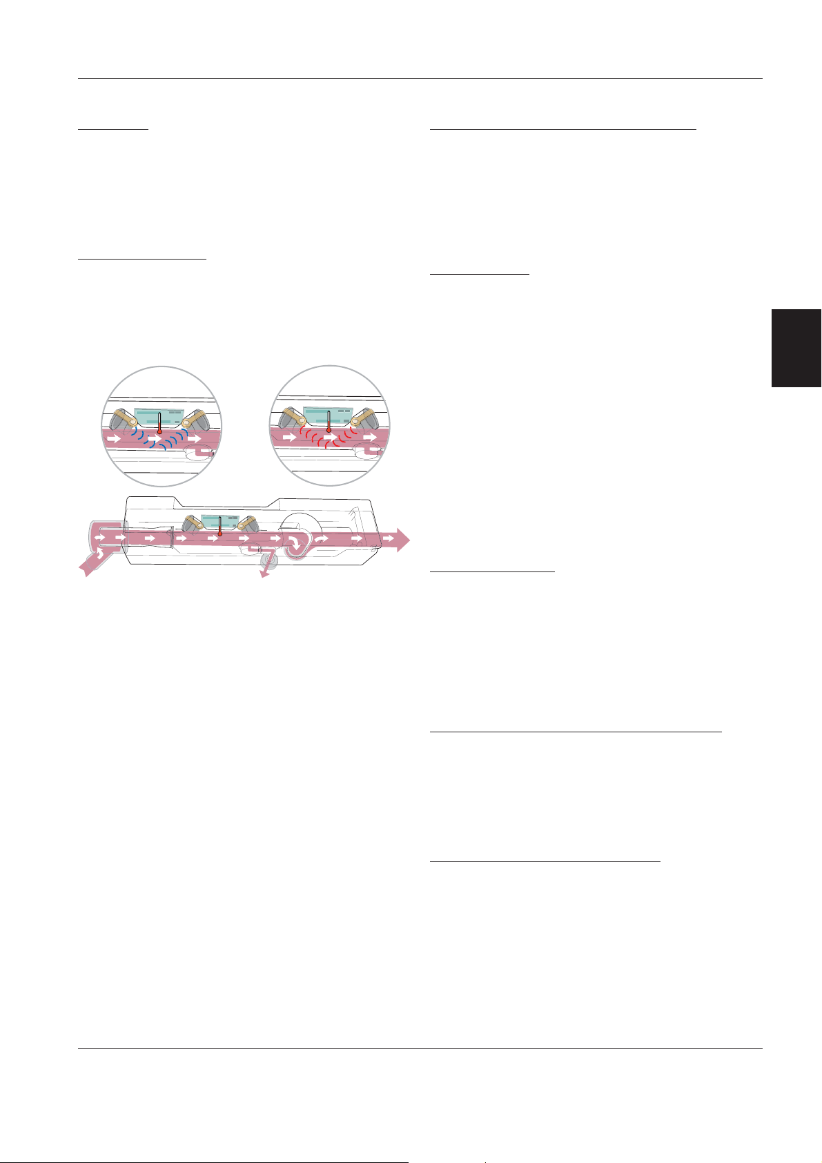
Internal fan
The Internal Fan forces cooling air through the
Patient Unit. The cooling air flow inside the Patient
Unit is indicated in the 'Functional Main Block
Diagram'.
The Internal Fan is controlled by the Temperature
Sensor on PC 1863 Power control. The fan will start
with half effect at approx. 33 °C (91 °F) and with full
effect at approx. 43 °C (109 °F). When the
temperature drops below approx. 37 °C (99 °F), the
fan turns to half effect and when the temperature
drops below approx. 27 °C (81 °F), the fan stops.
The air inlet is protected by a filter that must be
cleaned or replaced during the 'Preventive
maintenance'.
Control cable
This Control cable connects the Patient Unit and the
User Interface. The cable can be partly winded up
under a rubber cover on the rear of the User
Interface.
Note: The Control cable must only be connected or
disconnected when the ventilator is switched Off.
3
Revision 02 Service Manual 3 - 11
Page 30

Description of functions SERVO-s Ventilator System
Optional equipment
Alarm output connector (optional)
The Alarm output connector P63 is integrated in
PC 1862 DC/DC & Standard connectors and
mounted on all units. The 'Alarm output'-option must
however be enabled in the configuration software to
access this function.
The Alarm output connector enables connection of
an external alarm signal system to the SERVO-s.
High and medium priority alarms are transferred, and
the alarm output signal is active as long as the audio
alarm is active on the ventilator.
The Alarm output connector has two contact
3
functions: NO (Normally Open) and NC (Normally
Closed). In an alarm situation the open contact will
close and the closed one will open. The contacts are
independent of polarity and can be used both with
AC and DC systems.
Pin configuration and signal names in P63 – Alarm
output connector can be found in chapter 'Diagrams'.
For further information, refer to the 'Alarm output
connector – Reference Manual'
Loudspeaker booster kit (optional)
By installing the accessory 'Loudspeaker booster kit',
the alarm sound is amplified in a mechanical way.
The sound level will be increased significantly. This
increased sound level will raise the complete alarm
sound setting range (20%–100%), i.e. also the lower
sound level range will be increased.
The Loudspeaker booster consists of a rubber collar
that is mounted onto the loudspeaker to direct the
sound towards the loudspeaker grid.
All parts required for the installation are included in
the Loudspeaker booster kit.
Isolation shield with drip guard (optional)
The optional Isolation shield with drip guard is
connected to the Expiratory cassette outlet.
The accessory will not affect the expiratory
resistance of the system.
The main purpose of this accessory is to protect the
expiratory outlet pipe from direct cooling draught
favoring condensation.
The drip guard will also collect water that may be
condensed during ventilation in connection with use
of dual-heated patient tube during active
humidification. The water collector has a maximum
volume of 100 ml.
3 - 12 Service Manual Revision 02
Page 31

SERVO-s Ventilator System Disassembling and assembling
Only personnel trained and authorized
by MAQUET shall be permitted to
perform installation, service or
maintenance of the SERVO-s.
Make sure to prepare the SERVO-s properly
before disassembling and assembling. Refer to
section 'Hazard notices' in chapter 'Important'.
Any service or maintenance must be noted in a
log book.
After any installation, maintenance or service
intervention in the SERVO-s, perform a 'Pre-use
check'. Refer to the 'SERVO-s Ventilator System –
User's Manual' for details.
This product contains electronic and
electrical components. Discard
disposable, replaced and left-over parts
in accordance with appropriate industrial
and environmental standards.
4.Disassembling and
assembling
General .............................................................. 4 - 2
Preparations ...................................................... 4 - 2
Handling PC boards .......................................... 4 - 2
Replacing PC boards ........................................ 4 - 2
Assembling guidelines ...................................... 4 - 2
Tightening torque ........................................... 4 - 2
Threadlocking adhesives ............................... 4 - 2
User Interface .................................................... 4 - 3
PC 1777 Panel................................................ 4 - 4
Backlight inverter ........................................... 4 - 6
TFT Display ..................................................... 4 - 7
Backlight lamps .............................................. 4 - 9
Touch screen including frame ....................... 4 - 10
Membrane foil ................................................. 4 - 12
Patient Unit ........................................................ 4 - 14
4
Main and side covers ..................................... 4 - 14
Remove the User Interface from
the Patient Unit............................................... 4 - 15
Gas modules .................................................. 4 - 15
Battery modules ............................................. 4 - 16
PC 1771 Control and PC 1772 Monitoring.... 4 - 16
AC/DC Converter ........................................... 4 - 16
PC 1863 Power control .................................. 4 - 17
PC 1862 DC/DC & Standard connectors ...... 4 - 17
PC 1860 Main back-plane ............................. 4 - 17
Internal fan ...................................................... 4 - 18
Inspiratory channel ......................................... 4 - 18
Safety valve membrane.................................. 4 - 18
PC 1861 Pneumatic back-plane .................... 4 - 19
PC 1784 Expiratory channel .......................... 4 - 19
PC 1785 Expiratory channel connector......... 4 - 20
Expiratory valve coil ....................................... 4 - 20
Expiratory cassette membrane ...................... 4 - 21
Control cable ..................................................... 4 - 22
Revision 02 Service Manual 4 - 1
Page 32

Disassembling and assembling SERVO-s Ventilator System
General
Disassembling of the SERVO-s is described in this
chapter. If not stated otherwise, the assembling
procedure is the reverse of the described
disassembling procedure.
The illustrations in the SERVO-s Spare Parts List are
very useful as a guide when disassembling and
assembling the SERVO-s.
Preparations
Before disassembling or assembling the SERVO-s:
• Set the On / Off switch on the User Interface to
Off.
• Disconnect the mains power cable.
• Disconnect the gas supplies (wall and/or
4
cylinder).
• Make sure that all gas conveying parts are
cleaned according to instructions in the
'SERVO-s Ventilator System – User's Manual'.
After any service intervention in the SERVO-s,
perform a 'Pre-use check' according to
instructions in the 'SERVO-s Ventilator System –
User's Manual'.
Handling PC boards
The PC boards contain components
that are highly sensitive to static
electricity.
Those who come into contact with
circuit boards containing sensitive
components must take certain precautions to avoid damaging the
components (ESD protection).
When working with ESD sensitive components,
always use a grounded wrist band and grounded
work surface. Adequate service tools must also be
used.
PC boards (spare parts) must always be kept in
protective packaging for sensitive electronic device.
PC boards must not be inserted or removed while
the mains power or battery power is applied to the
PC boards.
Remove and insert the PC boards very carefully to
avoid damage to the connectors.
Replacing PC boards
The SERVO-s System SW is distributed on different
subsystems, located on the following PC boards:
• PC 1771 Control
• PC 1772 Monitoring
• PC 1784 Expiratory Channel
• PC 1777 Panel.
When delivered as spare parts, these PC boards are
equipped with a 'System SW version' that may differ
from the version on the unit to be repaired.
To keep the 'System SW version' used prior to the
PC board replacement, the applicable 'System SW
version' must be available on a PC Card for reinstallation purposes.
For functionality enhancement, the latest released
'System SW version' is always recommended.
Before installing a new 'System SW version' on a unit,
ensure that the software is fully compatible with all
HW-, SW- and mechanical components in the unit.
If any compatibility conflicts are apparent this will be
noted on the 'MCC SW download' website.
Assembling guidelines
All parts of the unit assembled with screws and nuts
are tightened with a specified torque. In the User
Interface, some of the screws are also secured with
threadlocking adhesives as noticed during
disassembling.
In order to maintain these specifications over time,
it must be ensured that after any service intervention
removed parts are re-assembled and secured
according to instructions. Make sure to follow the
guidelines stated below.
Tightening torque
• Thread size M3: 0.95 ±0.05 Nm
• Thread size M4–M6: 3.1 ±0.1 Nm.
Threadlocking adhesives
• Electrolube Bloc'Lube BLV15ML® on threads in
contact with PC boards.
• Loctite 243® on all other threads.
4 - 2 Service Manual Revision 02
Page 33

SERVO-s Ventilator System Disassembling and assembling
User Interface
With power supply connected to the
SERVO-s, there are energized electrical
components inside the unit, e. g. the
backlight lamps that are supplied with
660 V by the Backlight Inverter.
All personnel must exercise extreme caution if
fault tracing or adjustments are performed with
power supply connected and with the user
interface rear cover removed.
H
ServoS-9021
<
There are two different versions of the User Interface.
In this manual, they are described as:
• Type 1 – Up to User Interface S/N 201200
(SERVO-s S/N 02000).
• Type 2 – User Interface S/N 201201
(SERVO-s S/N 02001) and higher.
The electronics inside the User Interface differs and
as a consequence, some of the spare parts are not
compatible between the two versions. Further
information can be found below and also in the
SERVO-s Spare Parts List.
H6
The User Interface in the adjacent illustration is
equipped with the On/Off switch cover introduced
Q2 2007. Refer to section 'PC 1777 Panel' for further
information.
To separate the front panel section from the rear
cover:
• Disconnect the control cable (1).
• Remove the screws (2). Threadlocking adhesive is
not used on these screws.
• Lift off the rear cover from the front panel section.
All parts inside the front panel section are now
accessible.
When removing the rear cover:
• The PC Card eject button can catch on the PC
Card slot during disassembling. Carefully release
the button from the rear cover before removing the
cover.
HHH
When mounting the rear cover on units with the new
version of the On/Off switch and switch cover:
• The switch must be set to 'On' before mounting
the rear cover. If set to 'Off', the switch lever will
not enter the hole in the switch cover.
4
The main parts of the User Interface are:
• Rear cover (3).
• PC 1777 Panel (4).
• Backlight Inverter (5).
• Support plate (6).
• TFT Display (7) including Backlight lamps.
• Touch screen incl. frame (8).
ServoS-9089
Revision 02 Service Manual 4 - 3
=;?@9
Page 34

Disassembling and assembling SERVO-s Ventilator System
PC 1777 Panel
PC 1777A – D = Type 1
PC 1777F or higher = Type 2
HH
To remove PC 1777 Panel (1):
• Carefully disconnect all cable connectors from
PC 1777.
• Remove the screws (2) holding PC 1777.
• Lift off PC 1777.
Note: When replacing PC 1777 Panel, it can be
necessary to re-install the System SW. For further
information, refer to section 'Replacing PC boards' in
this chapter. For PC 1777 of Type 2, System SW
version V2.00.04 or higher is required.
4
ServoS-9022
Type 1 = PC 1777A – D
HH
ServoS-9020
Type 2 = PC 1777F or higher
HH6
A new design of the On/Off switch was introduced
Q2 2007. This switch also requires a new version of
the switch cover. Refer to illustrations below.
With this new design, the switch cover will be kept
open when the switch is Off and will be closed only
when the switch is On.
PC 1777 Panel, when delivered as spare part, will be
equipped with the new design of the On/Off switch.
HH6
The spare part will thus also include a new switch
cover to be mounted on the User Interface.
On/Off switch and switch cover - Old design
ServoS-9110
4 - 4 Service Manual Revision 02
On/Off switch and switch cover - New design
Page 35

SERVO-s Ventilator System Disassembling and assembling
Replacement of PC 1777 Type 1
PC 1777 Type 1 is discontinued and no longer
supplied as spare part. To replace such PC 1777, the
'Replacement kit for PC 1777A–D' must be used.
Note: The Disassembling/Assembling instructions
and the illustration below is valid only for the
'Replacement kit for PC 1777A–D'.
The kit contains all parts required for the
replacement:
• PC 1777 of Type 2 (6)
• PC 1777–TFT Display cable of Type 2 (10)
• Support plate (5)
• Cushion for the EMC filter (9)
• Retainer (12)
• Screw, M3x8 mm (24 each)
• Screw, M3x6 mm (4 each).
9;< ?.
=@ A
Disassembling
Installation of the replacement kit must be performed
in a clean and dustfree environment as the TFT
Display is sensitive to contaminations.
• Separate the front panel section from the rear
cover.
• Remove the loudspeaker (3) from the support plate.
• Remove PC board Backlight Inverter (4) from the
support plate (5).
• Remove the support plate including PC 1777 Panel
(6) and TFT Display (7) from the front panel section.
• Remove the TFT Display from the support plate.
• Discard the old PC 1777, the support plate and the
PC 1777–TFT Display cable of Type 1.
Assembling
• Check type and version of the TFT Display (7).
• Adapt the setting of the DIP switch (8) on the new
PC 1777 to the TFT Display. Refer to section 'TFT
Display' below.
• Mount the TFT Display (7) onto the new support
plate (5) using the new M3x6 mm screws.
• Attach the cushion (9) onto the EMC filter (11) as
shown in the illustration.
• Connect the cable (10) to the TFT Display.
Organize the cable, place the EMC filter in the
support plate recess and secure with the retainer
(12) as shown in section 'TFT Display' below.
• Mount the remaining parts onto the new support
plate. Use the new M3x8 mm screws.
– PC 1777 (6)
– PC board Backlight Inverter (4)
– Loudspeaker (3).
• Restore the complete assembly into the front panel
section.
• Connect all remaining cable connectors.
• Restore the User Interface.
4
Revision 02 Service Manual 4 - 5
Page 36

Disassembling and assembling SERVO-s Ventilator System
Backlight Inverter
Type 1
To remove the PC board Backlight Inverter (1):
• Carefully disconnect the cable connector (2).
9
;
6
H
;
9
• Carefully disconnect the backlight lamp cable
connectors (3).
• Remove the screws (4) holding PC board Backlight
Inverter.
• Lift off PC board Backlight Inverter.
4
;
@
?
A
<
@
A
=
ServoS-9023
Type 2
To remove the PC board Backlight Inverter (5):
• Carefully disconnect the cable connector (6).
• Carefully disconnect the backlight lamp cable
connector (7).
• Loosen the screws (8).
• Remove the screws (9) holding PC board Backlight
Inverter.
• Lift off PC board Backlight Inverter.
Note: When assembling, make sure that the plastic
washers on screws (8) are fitted between the PC
board and the screwhead.
ServoS-9095
4 - 6 Service Manual Revision 02
Page 37

SERVO-s Ventilator System Disassembling and assembling
TFT Display
Note: Disassembling of the TFT Display must be
performed in a clean and dustfree environment, as
the TFT Display is sensitive to contaminants.
6HH H
ServoS-9024
H
;;
9
HH
;
Type 1
The TFT Display is mounted under the support
plate (1). To remove the TFT Display:
• Carefully disconnect all cables from PC 1777.
The Backlight Inverter cable and the Loudspeaker
cable can remain connected.
• Carefully disconnect the Backlight lamp cables
from PC board Backlight Inverter.
• Remove the screws (2) holding the support plate.
• Lift off the support plate-assembly, including TFT
Display and PC boards.
4
Type 2
The TFT Display is mounted under the support
plate (3). To remove the TFT Display:
• Carefully disconnect all cables from PC 1777.
The Backlight Inverter cable and the Loudspeaker
cable can remain connected.
• Carefully disconnect the Backlight lamp cable from
PC board Backlight Inverter.
• Remove the screws (4) holding the support plate.
• Lift off the support plate-assembly, including TFT
Display and PC boards.
DIP switch on PC 1777 Type 2
Faulty DIP switch (5) setting will result in a reversed
display image.
ServoS-9094
;
Revision 02 Service Manual 4 - 7
;;
<
Settings for TFT Display:
• SHARP LQ12S41 • SHARP LQ121S1DG11
• NEC NL8060BC31-27
Page 38

Disassembling and assembling SERVO-s Ventilator System
• Remove the screws (6) holding the TFT Display to
the support plate.
ServoS-9025
=
Type 1
• Carefully release the Type 1-cable (7) from
PC 1777 as shown in the illustration.
4
ServoS-9026
ServoS-9106
ServoS-9109
?
@
Type 2
On units produced prior to Q2 2007, the Type 2cable is secured with a self-adhesive cushion
mounted on the cable connector at the TFT Display.
There is also a similar cushion on the cables EMCfilter.
• To disconnect; carefully release the Type 2-cable
A new locking device for the Type 2-cable was
introduced Q2 2007. This device replaces the
cushion mounted on the cable connector at the TFT
Display. The cushion on the EMC-filter remains.
• Slide the locking device (9) into position until it
• The adjacent illustration also shows PC 1777
AA
(8) from PC 1777 as shown in the illustration.
snaps in place. Note that there is no cushion on
the cable (10).
mounted onto the support plate and the Type 2cable connected to PC 1777. The locking device (9)
is visible between the support plate and PC 1777.
4 - 8 Service Manual Revision 02
Page 39

SERVO-s Ventilator System Disassembling and assembling
Units with 'Replacement kit for PC 1777A–D'
!.
ServoS-9096
• Carefully release the cable (11) from the recess on
PC 1777.
When assembling, make sure that the:
• Cushion (12) is attached to the EMC filter (13).
• EMC filter (13) is placed into the support plate
recess.
• Retainer (14) is mounted correctly.
Backlight lamps
Using the Field Service System (FSS), a time meter
for the lamps can be shown. This time meter must be
reset after replacement of the lamps.
ServoS-9027
Type 1
4
66H
66H
The Backlight lamp kit for TFT Display Type 1
includes two lamps. Always replace both lamps at
the same time.
To access the Backlight lamps:
• Lift off the TFT Display. Refer to section 'TFT
Display'.
• Remove the screws (1) holding the lamp.
• Lift off the lamp (2).
Type 2
On TFT Display Type 2, only one Backlight lamp is
required.
To access the Backlight lamp:
• Lift off the TFT Display. Refer to section 'TFT
Display'.
• Release the snap-in holder and pull out the lamp.
• Lift off the lamp (3).
ServoS-9097
9
Revision 02 Service Manual 4 - 9
Page 40

Disassembling and assembling SERVO-s Ventilator System
Touch screen including frame
The illustration shows Type 1, but the procedure for
Type 2 is the same.
To remove the Touch screen including frame (1):
• Lift off the TFT Display. Refer to section 'TFT
Display'.
• Remove the Main rotary dial (2):
– Pull off the Main rotary dial-knob.
– Remove the nut holding the Main rotary dial.
– Lift off the Main rotary dial.
• Remove the Direct access controls (3):
– Remove the cover on each Direct access control-
ServoS-9040
69H
4
knob.
– Loosen the nut on each knob and pull off the
knobs.
– Remove the nut holding each Direct access
control and lift off the controls.
Note: When mounting the Main rotary dial and the
Direct access controls on a new Touch screen incl.
frame, make sure that the knobs are easy to turn.
ServoS-9028
H
Label strips
The Touch screen including frame is delivered with
label strips which have to be mounted before the unit
is taken into operation. Protective foils (1) separate
the adhesive areas between the front panel film and
the front panel.
Mount the label strips as follows:
• Select the two appropriate label strips:
– One label strip for the Fixed keys on the upper
6
right-hand area, and
– One label strip for the Special functions keys on
the lower right-hand area of the User Interface.
Fixed keys label
• Insert the fixed keys label strip (2).
• Check its position through the button windows of
the front panel film. Adjust if necessary.
Align the label strip with great care. Once installed
the process cannot be reversed.
ServoS-9029
ServoS-9030
4 - 10 Service Manual Revision 02
Page 41

SERVO-s Ventilator System Disassembling and assembling
• While holding the label strip in correct position,
9
remove the protective foils (3 and 4).
• Press the label strip against the adhesive area.
;
ServoS-9031
ServoS-9033
ServoS-9035
<
=
@
ServoS-9032
ServoS-9034
?
• Remove the protective foil (5).
• Press the front panel film (6) firmly against the front
panel to ensure proper adhesion.
4
Special functions keys label
• Insert the Special functions keys label strip (7).
• Check its position through the button windows of
the front panel film. Adjust if necessary.
Align the label strip with great care. Once installed
the process cannot be reversed.
• While holding the label strip in correct position,
remove the protective foils (8 and 9).
• Press the label strip against the adhesive area.
A
ServoS-9036
ServoS-9037
• Remove the protective foil (10).
• Press the front panel film (11) firmly against the
front panel to ensure proper adhesion.
ServoS-9038
ServoS-9039
Revision 02 Service Manual 4 - 11
Page 42

Disassembling and assembling SERVO-s Ventilator System
Membrane foil
Note: The membrane foil (1) can only be replaced on
User Interface of Type 1.
ServoS-9125
4
ServoS-9126
ServoS-9127
H
6
To replace the membrane foil:
• Separate the front panel section from the rear
cover. Refer to section User Interface.
• Disconnect the membrane foil connector (2) from
PC 1777.
• Remove the four Direct access knobs.
• Pull off the old membrane foil.
ServoS-9128
ServoS-9129
• Remove all remainings from the old membrane foil
on the User Interface front panel. Clean the area for
the membrane foil with ethanol or isopropanol.
ServoS-9130
• Carefully separate the old membrane foil and
remove the label strip (3). The label strip must be
used on the new membrane foil.
Note: The label strip is not included in the
membrane foil spare part.
ServoS-9131
9
4 - 12 Service Manual Revision 02
Page 43

SERVO-s Ventilator System Disassembling and assembling
When assembling the membrane foils adhesive
parts, align the parts with great care. Once
installed the process cannot be reversed.
• On the new membrane foil:
– Carefully remove the protective foil (4).
– Attach the front panel film (5) onto the membrane
button panel.
– Press the front panel film firmly against the
membrane button panel to ensure proper
ServoS-9132
adhesion.
<;
• Remove the two remaining protective foils (6).
• Place the label strip (3) in correct position.
4
ServoS-9133
ServoS-9134
=9
ServoS-9135
ServoS-9136
@@
ServoS-9127
?
6
• Press the front panel film firmly against the
membrane button panel to ensure proper
adhesion.
• Remove the protective foils (7) and (8).
• Mount the membrane foil (1) onto the User
Interface front panel.
• Press the membrane foil firmly against the front
panel to ensure proper adhesion.
• Restore the User Inteface:
– Mount the four Direct access knobs.
– Connect the membrane foil connector to PC 1777.
Revision 02 Service Manual 4 - 13
Page 44

Disassembling and assembling SERVO-s Ventilator System
Patient Unit
Main and side covers
The main cover and the side cover are secured with
screws.
• Main cover screw (1).
• Side cover bayonet screws (2). To release or lock
these screws, turn the screw 90° as shown in the
illustration.
To open the Patient Unit main cover:
• Release the main cover screw (1).
• Pull the main cover (3) to stop.
The main cover is now partly open and the
inspiratory section is accessible.
4
ServoS-9043
69
ServoS-9044
ServoS-9046
To remove the Patient Unit main cover:
• Open the main cover as described above.
• Press the latch (4) and slide off the main cover (3).
9;
To remove the Patient Unit side cover:
• Release the side cover screws (2).
• Pull off the side cover (5).
With power supply connected to the
SERVO-s, there are energized electrical
components inside the unit. All
personnel must exercise extreme
caution if fault tracing or adjustments are
performed with power supply connected and with
the patient unit covers removed.
<H
4 - 14 Service Manual Revision 02
Page 45

SERVO-s Ventilator System Disassembling and assembling
Remove the User Interface from the
Patient Unit
To remove the User Interface from the Patient Unit:
• Disconnect the Control cable at the Patient Unit.
• Open the main cover.
• While firmly holding the User Interface (1), loosen
the screws (2).
• Lift off the User Interface.
ServoS-9042
6H
Gas modules
To remove the gas modules:
• Open the main cover.
• Loosen the two screws holding the locking rail (1).
• Pull off the gas modules (2).
4
ServoS-9045
6 H
9;;
ServoS-9041
Revision 02 Service Manual 4 - 15
When assembling, make sure that the connector
muff properly seals around the inspiratory pipe (3).
The connector muff must not be pushed too far onto
the nozzle units (4).
Page 46
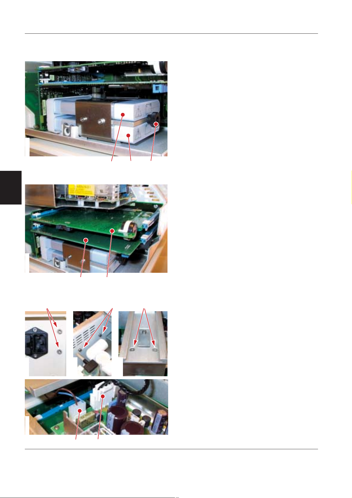
Disassembling and assembling SERVO-s Ventilator System
Battery modules
To remove the battery modules:
• Remove the main cover.
• Unscrew and remove the knob (3).
• Pull off the battery modules:
– Battery module in slot 1 (1)
– Battery module in slot 2 (2).
The battery modules to be used are the same as for
SERVO-i.
ServoS-9048
6
9H
Note: Replace both battery modules at the same
time.
PC 1771 Control and PC 1772 Monitoring
4
ServoS-9050
69H
ServoS-9059
ServoS-9058
To remove PC 1771 and/or PC 1772:
• Remove the main cover.
• Release both locking devices at the PC board
guides for the concerned PC board.
• Carefully pull out and lift off the concerned PC
board:
– PC 1771 Control (1)
– PC 1772 Monitoring (2).
Note: When replacing PC 1771 Control or PC 1772
Monitoring, it can be necessary to re-install the
System SW. For further information, refer to section
H6
'Replacing PC boards' in this chapter.
AC/DC Converter
To remove the AC/DC Converter:
• Remove the main cover.
• Remove the screws holding the AC/DC Converter:
– Screws (1) at the mains inlet
– Screws (2) inside the inspiratory section. Pull out
gas module to access the screws.
the O
2
– Screws (3) at the main cover rail.
ServoS-9060
• Carefully pull out the AC/DC Converter to make the
cable connectors accessible.
• Disconnect the mains power cable (4) and the
converter cable (5).
• Lift off the AC/DC Converter.
ServoS-9057
;
<
4 - 16 Service Manual Revision 02
Page 47

SERVO-s Ventilator System Disassembling and assembling
PC 1863 Power control
To remove PC 1863:
• Remove the main cover.
• Remove the battery modules.
• Remove the screws (1) at the underside of the
Patient Unit. These screws are accessible also with
the SERVO-s mounted on a Mobile cart.
• Carefully pull out and lift off PC 1863 (2).
ServoS-9051
ServoS-9053
ServoS-9061
ServoS-9052
ServoS-9054
H6
PC 1862 DC/DC & Standard connectors
To remove PC 1862:
• Remove the main cover.
• Remove the screws (1) on the rear panel.
4
• Carefully pull out and lift off PC 1862 (2).
H6
PC 1860 Main back-plane
To remove PC 1860:
• Remove the main cover.
• Remove the:
– Battery modules
– PC 1771 Control
– PC 1772 Monitoring
– PC 1863 Power control
– PC 1862 DC/DC & Standard connectors
– Internal fan.
• Disconnect the converter cable (1).
• Remove the screws (2).
• PC 1784 Expiratory channel and PC 1861 Pneu-
H69H
matic back-plane is connected to the rear side of
PC 1860. Carefully pull out and lift off PC 1860 (3).
Note: The ventilators System ID, configuration,
operating time, etc, is stored in an EEPROM on PC
1860. Thus, when replacing PC 1860, a spare part
that is factory programmed for the concerned
ventilator must be used. For further information refer
to chapter 'Description of functions'.
Revision 02 Service Manual 4 - 17
Page 48

Disassembling and assembling SERVO-s Ventilator System
Internal fan
To remove the internal fan:
• Remove the main cover.
• Remove PC 1862 DC/DC & Standard connectors
(to make the internal fan cable connector
accessible).
• Remove the internal fan filter.
• While holding the internal fan, remove the
screws (1).
ServoS-9055
ServoS-9056
6H
• Disconnect the internal fan cable connector (2)
• Lift off the internal fan.
Note: An arrow on the fan housing indicates the air
flow direction. When mounting the fan, make sure
that the cooling air flow is directed into the unit.
4
ServoS-9090
6
Inspiratory channel
Removal of the inspiratory channel, as well as
removal of O
in the User's manual.
Sensor and O2 cell/filter, is described
2
Safety valve membrane
To remove the safety valve membrane:
• Remove the inspiratory channel.
• Release the latches (1), one on each side of the
safety valve housing, and lift off the membrane
holder (2).
9;
H
• The membrane (3) and the valve seat (4) are now
accessible, e.g. for inspection and cleaning.
ServoS-9091
4 - 18 Service Manual Revision 02
Page 49
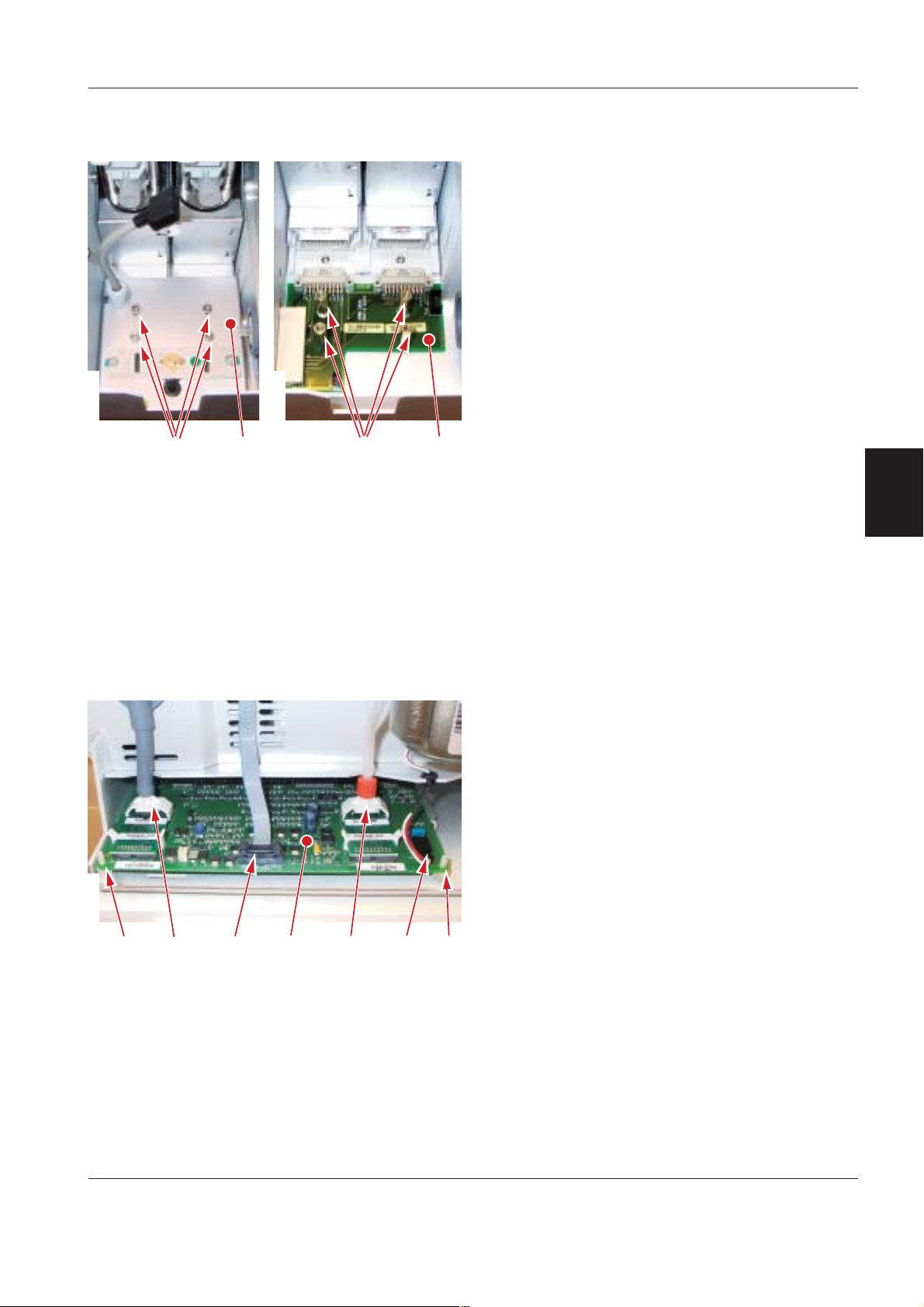
SERVO-s Ventilator System Disassembling and assembling
PC 1861 Pneumatic back-plane
To remove PC 1861:
• Remove the main cover.
• Remove PC 1860 Main back-plane. (PC 1861
cannot be removed with PC 1860 mounted.)
• Remove the inspiratory channel including filter for
the inspiratory pressure transducer.
• Remove the screws (1).
• Carefully lift the mounting plate (2) and disconnect
Sensor/cell connector and the safety valve
the O
2
pull magnet connector from PC 1861.
• Lift off the mounting plate (2). The safety valve pull
ServoS-9063
6
H
ServoS-9064
9
;
magnet is mounted on this plate.
• Pull out the gas modules to disconnect them from
PC 1861.
• Remove the threaded studs (3).
• Lift off PC 1861 (4).
Note: When assembling, the mounting plate (2) must
be adjusted to correspond with the inspiratory
channel latches.
4
ServoS-9065
6
H
9
;
PC 1784 Expiratory channel
To remove PC 1784:
• Remove the side cover.
• Disconnect the:
– Inspiratory pressure transducer tube (1)
– PC 1785 cable connector (2)
– Expiratory pressure transducer tube (3)
– Expiratory valve coil cable connector (4).
• Release PC 1784 from the standoffs (5).
• Carefully pull out and lift off PC 1784 (6).
Note: When replacing PC 1784 Expiratory channel,
<<=
it can be necessary to re-install the System SW.
For further information, refer to section 'Replacing
PC boards' in this chapter.
Revision 02 Service Manual 4 - 19
Page 50

Disassembling and assembling SERVO-s Ventilator System
PC 1785 Expiratory channel connector
4
ServoS-9066
ServoS-9067
ServoS-9068
66H
6
;
H
9
6
To remove PC 1785:
• Remove the side cover.
• Disconnect the PC 1785 cable connector (1).
• Remove the screws (2).
• Pull down and lift off PC 1785 (3).
Note: When assembling, make sure that the rubber
seal (4) is correctly seated around PC 1785.
Expiratory valve coil
To remove the expiratory valve coil:
• Remove the side cover.
• Disconnect pressure transducer tubes and cable
connectors from PC 1784. Refer to section 'PC
1784 Expiratory channel'.
• Remove the screws (1).
• Lift off the cassette compartment (2).
ServoS-9069
99
• Remove the screws (3).
• Lift off the expiratory valve coil (4).
ServoS-9070
99;
4 - 20 Service Manual Revision 02
Page 51
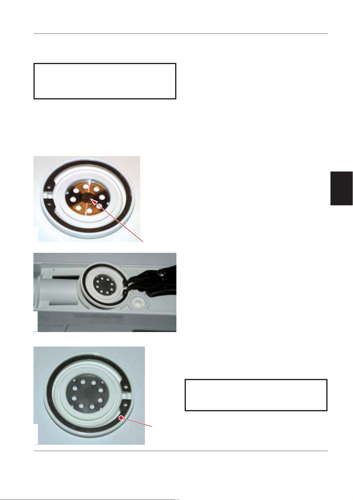
SERVO-s Ventilator System Disassembling and assembling
Expiratory cassette membrane
It is very important for the function of the
expiratory valve that the valve membrane is
removed and mounted correctly as described
below.
The expiratory cassette is a complete unit and must
not be disassembled. The only part that can be
replaced is the valve membrane.
Operating capacity for the membrane is estimated to
10.000.000 breathing cycles. When this limit is
passed or if the membrane for some reason has
become defective, it must be replaced.
Remaining operating capacity (in %) for the
membrane can be shown in the Status window.
Select Status / Exp. cassette to check 'Remaining
membrane capacity'. The operating capacity meter
must be reset after replacement of the membrane.
Note: If the metal washer has been separated from
the membrane, it is important that the washer is
correctly mounted.
• Washers of old version have a raised hub (1) that
must be facing outwards as shown in the adjacent
illustration.
• Washers of new version do not have this raised
hub and can be mounted in both directions.
4
ServoS-9107
ServoS-9071
6
To remove the valve membrane from the cassette:
• Carefully remove the membrane including retaining
ring using a suitable retaining ring pliers.
To mount the valve membrane into the cassette:
• Place the retaining ring (2) correctly into the
membrane.
It is very important that the valve membrane and
the membrane seat in the cassette is clean. Dirt
particles can create leakage in the cassette.
H
ServoS-9072
Revision 02 Service Manual 4 - 21
Page 52

Disassembling and assembling SERVO-s Ventilator System
• Place the membrane onto the cassette as shown in
the illustration.
ServoS-9071
• Squeeze the retaining ring pliers and carefully
press the membrane in place into the cassette as
shown in the illustration.
4
ServoS-9074
ServoS-9073
ServoS-9075
• Carefully release and remove the pliers.
• Check that the membrane is not deformed by the
retaining ring. If necessary, remove the membrane
and redo the complete mounting procedure.
• Mount the expiratory cassette onto the Patient
Unit.
• Reset the operating capacity meter after
replacement of the membrane. To access the reset
button, select Menu / Biomed / Service.
Control cable
The control cable connectors must be connected
carefully to avoid damages on the connector pins.
• Carefully find the correct position; the connector
pins and the guides in the connectors must
correspond. Do not turn the connector while
inserting!
• When correct position is found, insert the
connector.
• Secure the connector with its locking ring.
The illustration shows the Patient Unit connector, but
the procedure for the User Interface connector is the
same.
Note: The Control cable must only be connected or
disconnected when the ventilator is switched Off.
4 - 22 Service Manual Revision 02
Page 53

SERVO-s Ventilator System Service procedures
Only personnel trained and authorized
by MAQUET shall be permitted to
perform installation, service or
maintenance of the SERVO-s.
Make sure to prepare the SERVO-s properly
before disassembling and assembling. Refer to
section 'Hazard notices' in chapter 'Important'.
Any service or maintenance must be noted in a
log book.
After any installation, maintenance or service
intervention in the SERVO-s, perform a 'Pre-use
check'. Refer to the 'SERVO-s Ventilator System
– User's Manual' for details.
This product contains electronic and
electrical components. Discard
disposable, replaced and left-over parts
in accordance with appropriate
industrial and environmental standards.
5. Service procedures
Battery modules ................................................ 5 - 2
Replacing the lithium batteries on
PC 1771 and PC 1772 ...................................... 5 - 3
Using the Menu and Biomed key...................... 5 - 4
Menu ............................................................... 5 - 4
Biomed ........................................................... 5 - 4
Software installation .......................................... 5 - 6
General ........................................................... 5 - 6
Software information ...................................... 5 - 6
Software delivery ............................................ 5 - 6
Software installation procedure ..................... 5 - 6
Field Service System ......................................... 5 - 6
General ........................................................... 5 - 6
Field Service System functions ..................... 5 - 6
5
Revision 02 Service Manual 5 - 1
Page 54
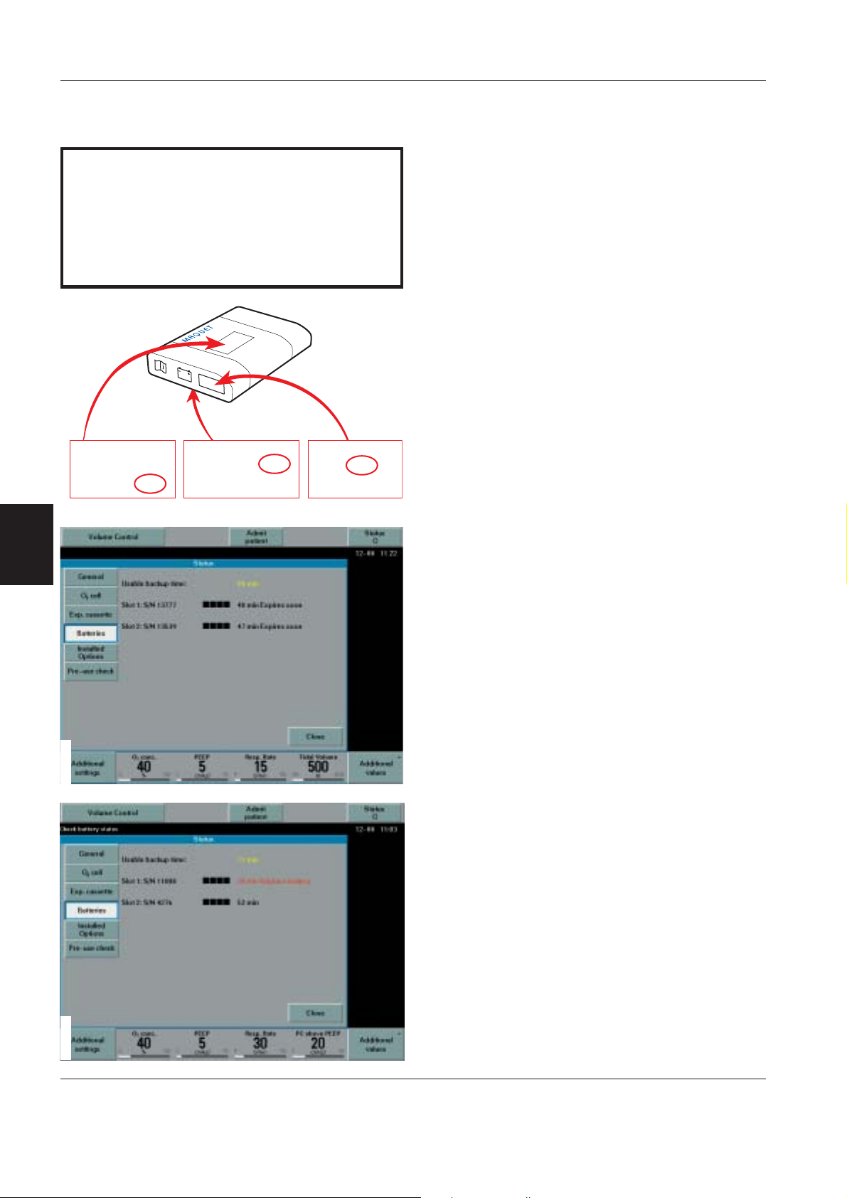
Service procedures SERVO-s Ventilator System
Battery modules
System SW version V2.01.00 (or higher) includes an
improved monitoring of the battery status. Select
'Status / Batteries' on the User Interface to check
battery status. Refer to the illustrations below.
On ventilators with this improved battery monitoring,
the batteries condition and capacity are verified
during the Pre-use check and also continuously
during operation of the unit. No further functions
checks of the batteries are required.
With this improved battery monitoring, the Battery
status window shows:
• Usable backup time. Calculated as the sum of the
estimated backup time for the connected Battery
modules reduced with 10 minutes as an extra
safety feature.
• Slot number. Note that slot 1 is the lower slot and
slot 2 is the upper.
• Battery module S/N.
• Charge indicator for each battery, where:
0 boxes filled = < 10% relative charge
1 box filled = 10–25% relative charge
2 boxes filled = 26–50% relative charge
3 boxes filled = 51–75% relative charge
4 boxes filled = 76–100% relative charge
Recharge time for a discharged battery is approx.
3 hours/battery. If a battery is fully discharged, e.g.
due to long storage time, it may require up to 12
hours charging time.
With the charge status indicator on the User
Interface, the four green LEDs on the Battery
module are no longer required and will be removed
from the modules.
• Remaining operating time in minutes for each
battery.
Furthermore, an activity instruction, displayed
directly next to the operating time, may show:
• Expires soon. Message activated if expiry date will
be reached within 60 days.
• Replace battery. The battery must be replaced and
discarded. Message activated if:
– The batteries expiry date is passed and its life
span is exceeded. Note: Due to the age of the
battery, the calculated backup time may in this
case not be reliable. Even if the battery indicates
a significant backup time, the battery must be
replaced.
or
– The batteries operational capacity is too poor for
continued usage, caused e.g. by the chemical
process in an aging battery.
5
The life span for the Battery module is calculated
to two and a half year from manufacturing date.
Normal time for logistics and storage are
included in this calculation. The calculation
corresponds thus to an estimated operational
time of two years. Manufacturing date (yearweek) is printed on the battery label.
Manufacturing
date = YYWW
(YearWeek)
Version 1 Version 2 Version 3
Batteri Module
Part No:. 64 87 180 E407E
Manufacturing Date: 0245
Hardware Version: xxxxx
ServoS-9101
ServoS-9099ServoS-9100
Manufacturing Date :
Hardware Revision :
Batch No :
0420
xxxxx
xxxxx
Man. Date : 0520
S N xxxxx
5 - 2 Service Manual Revision 02
Page 55

SERVO-s Ventilator System Service procedures
Replacing the lithium batteries on
PC 1771 and PC 1772
The lithium batteries must be replaced after 5 years.
A Technical error message will appear on the screen
if the battery voltage level is too low.
Always replace both batteries at the same time to
keep the same replacement date for both batteries.
Preparations
• Set the On/Off switch on the control unit to Off.
• Disconnect the mains power cable.
• Disconnect the gas supplies (wall and/or cylinder).
• Remove patient tubing.
Replacing the lithium battery
• The lithium batteries are mounted on ESD sensitive
PC boards. Refer to chapter 'Disassembling and
assembling', section 'Handling PC boards' for
further information regarding ESD sensitive
components.
• Remove the Patient Unit main cover. Refer to
chapter 'Disassembling and assembling'.
• Carefully pull out PC 1771 and PC 1772.
ServoS-9078
H9
6
;
• There are two equal battery connectors (2 and 3)
• Cut the cable ties holding the old battery (4) to the
• Disconnect and remove the old battery.
• Mount the new battery onto the PC board using
• Insert the PC board into the correct PC-board slot
After any maintenance or service of the SERVO-s,
perform a 'Pre-use check'. Refer to the 'SERVO-s
Ventilator System – User's Manual'.
Do not remove the cable connector (1).
Note:
Information stored in the PC board memory will be
erased if the connector is removed:
– If the battery on PC 1771 is disconnected;
user default configurations made via the Field
Service System (FSS) and Pre-use check results
including transducer calibrations will be erased.
– If the battery on PC 1772 is disconnected;
all trends, all logs and Pre-use check results
including transducer calibrations will be erased.
on the PC boards. Connect the new battery to the
un-used connector. The memory functions are now
secured by the new battery.
PC board.
new cable ties as shown in the illustration.
and reassemble the Patient Unit.
5
Revision 02 Service Manual 5 - 3
Page 56

Service procedures SERVO-s Ventilator System
Using the Menu and Biomed key
The 'Menu' and 'Biomed' functions are useful tools
during service.
The adjacent flowchart shows the 'Biomed' functions
in System version V3.1. A complete set of flowcharts
showing all 'Keys' and 'Screen touch pad' functions
can be found in the 'SERVO-s Ventilator System –
User's Manual'.
5
Biomed
Service
Event log
Alarms
Ventilator settings
Apnea periods
Functions
Latest
Time selection
Service log
Technical alarms
Test results
Preventive
Maintenance
Service report
history
Installation
log
Latest
Time selection
Report PM
Replaced Exp
membrane
Edit
configuration
Alarm
sound level
Alarm
limits
Displayed
values
NIV
alarms
Startup
configuration
Copy
configuration
Set date
and clock
Enter code 1973 to access the
Biomed menues.
Display Event logs.
Possible selections:
• Latest logs
• Selected time interval
Display Service logs.
Possible selections:
• 21 latest logs
• Selected time interval
Enters date for a performed Preventive Maintenance
into the Service Log. Setting time stamp until next PM.
Reset of breath counter in expiratory cassette.
User default configuration setup.
Copy configuration to / from PC Card.
Date and time setup.
Menu
Pressing the fixed key 'Menu' will open the 'Menu
window' on the User Interface.
The 'Menu' is active in Standby and during ventilation
mode, but the available submenus differs.
Possible selections in the 'Menu' window are:
• Alarm
• Review
• Complience compensation
• Biomed
• Panel lock
Biomed
Submenu 'O2 cell adaptation', active only during
ventilation modes in units with O
code is required.
All other 'Biomed' submenus are available only
during Standby and requires an access code. The
default code is 1973, but the code can be changed in
the Biomed menu.
Service
Available only in Standby mode.
Event Log:
Displays Event logs. Useful during troubleshooting.
Service Log:
Displays Service logs. Useful during troubleshooting.
Report PM:
This button must be pressed when a Preventive
Maintenance has been performed. This will reset the
timer that indicates operating hours until next
Preventive Maintenance. Default value is 5,000 hours.
In the Report PM submenu, it is possible to enter a
new value, e.g. if the time stamp was erased during a
SW installation.
cell. No access
2
ServoS-9092
Change
access code
O
2
cell
adaptation
Change access code to Biomed menu.
Measured O2 concentration will be adapted in
relation to set value.
5 - 4 Service Manual Revision 02
Page 57

SERVO-s Ventilator System Service procedures
Replaced Exp membrane:
This button must be pressed when the Expiratory
cassette membrane has been replaced. This will
reset the operating capacity meter (breath counter) in
the expiratory cassette.
Edit configuration
Available only in Standby mode.
Alarm sound level
Default alarm sound level can be changed in this
window.
Alarm limits
Default invasive alarm limits can be changed in this
window:
• Pressure – Upper alarm limit
• Minute Volume – Lower and Upper alarm limit
• Respiratory Rate – Lower and Upper alarm limit
• End Exp. Pressure – Lower and Upper alarm limit
• Apnea time – Upper alarm limit.
Default configuration regarding 'General' and 'Units'
cannot be changed in this window. Access to the
Field Service System (FSS) is required.
Startup configuration
Requires Software Version 3. Startup configuration
can be changed in this window:
• Type of ventilation
• Volume setting
• Breath Cycle setting
• Pre-post oxygenation conc. above set O
conc.
2
Copy configuration
Available only in Standby mode.
Default user configuration can be copied to / from a
PC Card.
Default configuration regarding 'General', 'Units' and
'Alarm limits' will be copied.
Useful when applying the same user configuration on
a number of units.
Set date and clock
Available only in Standby mode.
Date and time setting can be changed in this
window.
5
Displayed values
The Measured value boxes on the User Interface
shows different parameters. Some of these
parameters are fixed and some are selectable in this
window.
NIV alarms
Default NIV alarms can be changed in this window:
• Pressure – Upper alarm limit
• Minute Volume – Lower and Upper alarm limit
• Respiratory Rate – Lower and Upper alarm limit
• End Exp. Pressure – Lower and Upper alarm limit
The alarms listed above, except Pressure alarm, can
be permanently silenced in this window.
Default configuration regarding 'General' and 'Units'
cannot be changed in this window. Access to the
Field Service System (FSS) is required.
Change access code
Available only in Standby mode.
Access code to the 'Biomed' menu can be changed
in this window.
cell adaptation
O
2
Available only during ventilation in units with O
Adjustment of the O
concentration reading.
2
cell.
2
Refer to the 'SERVO-s Ventilator System – User's
Manual' for further information.
Revision 02 Service Manual 5 - 5
Page 58

Service procedures SERVO-s Ventilator System
Software installation
General
• Before starting any SW Upgrade or Update, check:
– Installed System SW version (see 'System SW
version' in the Status / General window)
– System SW version stored on the PC Card.
not recommended to install System SW with
It is
lower version number than already installed in the
SERVO Ventilator System.
• After any installation, maintenance or service
intervention in the SERVO-s, perform a 'Pre-use
check' according to instructions in the 'SERVO-s
Ventilator System
Software information
There are two different intentions for software
installation:
SW Update
A SW Update will install a new System SW version in
the SERVO Ventilator System. SW Updates are not
dependent on the serial number of the ventilator and
will not alter the installed SW Options.
5
SW Upgrade
A SW Upgrade will change the function of the
SERVO Ventilator System. A SW Upgrade is
individually created for each ventilator and can only
be installed on this ventilator. S/N of the ventilator
must be stated when ordering a SW Upgrade.
SW Upgrade
Option Upgrade
All System versions
– User's Manual'.
SW Option
SW Option
SW Option
SW Option
SW Option
SW Update
Software delivery
SW Updates and SW Upgrades can be downloaded
from the 'MCC SW Download' website or delivered
via freight on a PC Card.
• SW Updates are not dependent on the S/N of the
ventilator and can thus be installed on any unit.
• SW Upgrades are specific for each ventilator and
can only be installed on this unit. SW Upgrades
must thus be ordered and created in factory before
they can be available on the website or delivered
on a PC Card.
Software installation procedure
Further information regarding the different softwares
and the software installation procedure can be found
in the 'SERVO-i / SERVO-s Software – Installation
Instructions'.
Field Service System
General
• The Field Service System (FSS) is a software
provided to facilitate troubleshooting, service and
maintenance of the SERVO Ventilator System.
• To access the Field Service System, a Service card
(PC Card) and an access code must be used.
The access code is unique for each Service card.
• The Service card is personal and
handed-over to anyone else.
• It is only possible to access the Field Service
System with the ventilator in Standby mode.
• The Field Service System must not be activated
with a patient connected the ventilator.
must not be
Major
function
improvement
Software Version
System version V3.0 or higher
ServoS-9105
5 - 6 Service Manual Revision 02
Corrections
and minor
function
improvement
SW Service Release
System version V3.0 or higher
Field Service System functions
In the Field Service System, it is possible to:
• Display information regarding the ventilator
including options and parts installed.
• Calibrate the internal barometer.
• Display service and event logs.
• Run complete or selected test sequences.
System SW Update
System version V1.0 - V2.1
• Create and save service reports.
• Export selected logs to a PC Card.
• Create user default configurations.
Page 59
SERVO-s Ventilator System Troubleshooting
Only personnel trained and authorized
by MAQUET shall be permitted to
perform installation, service or
maintenance of the SERVO-s.
Make sure to prepare the SERVO-s properly
before disassembling and assembling. Refer to
section 'Hazard notices' in chapter 'Important'.
Any service or maintenance must be noted in a
log book.
After any installation, maintenance or service
intervention in the SERVO-s, perform a 'Pre-use
check'. Refer to the 'SERVO-s Ventilator System –
User's Manual' for details.
This product contains electronic and
electrical components. Discard
disposable, replaced and left-over parts
in accordance with appropriate industrial
and environmental standards.
6. Troubleshooting
General .............................................................. 6 - 2
Pre-use check ................................................... 6 - 3
Technical error codes........................................ 6 - 11
6
Revision 02 Service Manual 6 - 1
Page 60

Troubleshooting SERVO-s Ventilator System
Possible causes to malfunction not mentioned in
the following troubleshooting guides are:
• The system has not been correctly assembled
after cleaning, maintenance or service.
• Disconnection or bad connection in cable
connectors, PC board connectors, and interconnection boards.
• Disconnected or defective gas tubes.
These possible causes to malfunction must
always be considered during troubleshooting.
General
Before starting troubleshooting, try to eliminate all
possibilities of operational errors. If the malfunction
remains, use the troubleshooting guides below as
well as the information in chapter 'Description of
functions' to locate the faulty part. Perform actions
step by step and check that the malfunction is
eliminated.
When the fault is corrected, carry out a complete
'Pre-use check' as described in the 'SERVO-s
Ventilator System – User's Manual'.
The troubleshooting guides below are focused only
on technical problems. Information about clinical
related problems can be found in the 'SERVO-s
Ventilator System – User's Manual'.
6
For functionality enhancement, the latest released
System SW version is always recommended.
The Information in this chapter applies to System
version V3.1 (or higher).
6 - 2 Service Manual Revision 02
Page 61

SERVO-s Ventilator System Troubleshooting
Pre-use check
The SERVO-s demands the user to start the
automatic Pre-use check at every startup of the unit.
It is also possible to select the Pre-use check via the
Standby menu.
The 'SERVO-s Ventilator System – User's Manual'
describes how to perform this Pre-use check. The
Pre-use check-description on the following pages
gives more detailed information about the Pre-use
check. This information can be used e.g. during
troubleshooting of the unit.
* Text within brackets refers to the tested subsystem; BRE = Breathing, MON = Monitor, PAN = Panel.
Test Test description * Recommended action if the test fails
During system startup.
Internal technical tests:
• SW check
• Reading EEPROM
• Checksum EEPROM
• Panel button stuck test
• Audio test.
(BRE + MON + PAN)
Some of the recommended actions described below
refer to the Field Service System (FSS). The Service
card is required to access the FSS. Troubleshooting
can of course be performed without access to the
FSS, but for some of the recommended actions, the
FSS will make troubleshooting faster and easier.
Check if the fault remains after each performed
service action. Re-run the complete Pre-use check
or run the concerned test using the FSS.
Via the Standby menu it is possible to perform a
separate Patient circuit test to evaluate circuit
leakage and measure circuit compliance. This test
does not replace the complete Pre-use check.
1. Restart the unit. Do not touch the
User Interface during system startup. Interfering with the knobs,
keys, touch screen, loudspeaker
grid, etc, may affect the internal
technical tests.
2. Reinstall the System SW.
6
Start Pre-use check
Internal tests
Revision 02 Service Manual 6 - 3
Audio test.
(MON + PAN)
Alarm output connector test.
Performed only if this option is
installed.
(MON)
Power failure test.
(MON)
If possible, check the ‘Test results’-log
in the ‘More detailed’ mode (FSS).
If the audio test failed:
1. Make sure that the Patient Unit
main cover and the User Interface
rear cover are correctly mounted.
Otherwise the audio tests may fail.
2. Check in the Test results-log (FSS)
if it was the Panel test or the
Monitoring test that failed:
• If the Monitoring test failed:
Replace PC 1772 Monitoring.
• If the Panel test failed:
Replace the loudspeaker or
PC 1777 Panel.
Page 62

Troubleshooting SERVO-s Ventilator System
Test Test description * Recommended action if the test fails
Internal tests
(continued)
Barometer test Checks that the barometric pressure
measured by the internal barometer is
within 630–1080 hPa.
Checks that the measured barometric
pressure values differs less than 8 hPa
between BRE and MON.
(BRE + MON)
If the Alarm output connector test
failed:
1. Replace PC 1862 DC/DC &
Standard Connectors.
2. Replace PC 1772 Monitoring
If the power test failed:
1. Replace PC 1772 Monitoring.
Check the Barometric pressure value in
the Status window:
If that value is within 630–1080 hPa:
1. Replace PC 1771 Control
2. Replace PC 1772 Monitoring
3. Replace PC 1784 Expiratory
channel
4. Replace the gas modules. Replace
one gas module at a time.
If that value is outside 630–1080 hPa:
6
Gas supply pressure
test
Checks that the gas supply pressures
(Air and O
) measured by the internal
2
gas supply pressure transducers are
within 200–650 kPa (2.0–6.5 bar).
Checks that the measured supply gas
pressure values differs less than
20 mbar between MON and BRE.
(BRE + MON)
1. Replace PC 1772 Monitoring.
1. Check that the connected gas
supply pressure (Air and O
) is
2
within the specified range.
2. Start the unit in a ventilation mode
and check the alarms:
• If an Air supply pressure-alarm
is activated, replace the Gas
module Air.
• If an O
supply pressure-alarm
2
is activated, replace the Gas
module O
.
2
3. Replace PC 1771 Control.
4. Replace PC 1772 Monitoring.
6 - 4 Service Manual Revision 02
Page 63

SERVO-s Ventilator System Troubleshooting
Test Test description * Recommended action if the test fails
Internal leakage test Checks the internal leakage, with test
tube connected, using the inspiratory
and expiratory pressure transducers.
Checks that the leakage at 80 cm H
is max. 10 ml/min.
Checks that the measured pressure
values differs less than 5 cm H
between Insp. and Exp.
(BRE)
2
O
2
If message ‘Leakage’ or ‘Excessive
leakage’ appears:
1. Check that the test tube is
O
correctly connected.
2. Check the expiratory cassette:
• Check that the cassette is
correctly seated in the cassette
compartment.
• If possible, replace the
expiratory cassette and check if
the new cassette is accepted by
the Pre-use check.
• If the new cassette was
accepted by the Pre-use check,
the fault was located to the
cassette. To repair the old
cassette, check that the
expiratory valve membrane is
clean and correctly seated in
the cassette. Replace the
membrane if required.
3. Check that the pressure transducer
tubes/filters are correctly mounted.
4. Check the inspiratory section:
• Check that the inspiratory pipe
is correctly mounted in the
inspiratory section.
• Check that the safety valve
membrane is clean and
correctly seated in the
inspiratory pipe.
• Check that the safety valve
closes properly when the Preuse check is started (distinct
clicking sound from the valve).
If the safety valve opens during
this test, the opening pressure
may not be correctly calibrated
(see ‘Safety valve test’ below).
Run the ’Safety valve test’ and
repeat the complete Pre-use
check.
6
Revision 02 Service Manual 6 - 5
Page 64

Troubleshooting SERVO-s Ventilator System
Test Test description * Recommended action if the test fails
Internal leakage test
(continued)
If message ‘Pressure Transducer
difference > 5 cm H
1. Check that the pressure transducer
tubes and the inspiratory filter are
correctly mounted.
2. Check that both PC 1781 Pressure
transducer (Insp. and Exp.) are
correctly mounted.
3. If the ‘Pressure transducer test’
also fails (see below), refer to the
recommended actions if ‘Pressure
transducer test’ failed.
If message ‘System volume too small’
appears:
1. Replace the gas modules. Replace
one gas module at a time.
If message ‘System volume too large’
appears:
1. Check that the correct test tube is
used during the Pre-use check.
O’ appears:
2
6
2. If the ‘Flow transducer test’ also
fails (see below), replace the gas
modules. Replace one gas module
at a time.
3. Refer to troubleshooting as
described for ‘Leakage’ or
‘Excessive leakage’ above.
6 - 6 Service Manual Revision 02
Page 65

SERVO-s Ventilator System Troubleshooting
Test Test description * Recommended action if the test fails
Pressure transducer
test
Calibrates and checks the inspiratory
and expiratory pressure transducers.
The new zero value for the pressure
transducers may not differ more than
±6 cm H
With the inspiratory pressure
transducers used as a reference, a new
gain factor is set for the expiratory
pressure transducer. The new gain
factor may not differ more than ±5%
from factory calibration.
During this test, the different
subsystems concerned are compared.
The difference between the
subsystems must not be more than
±1 cm H
Expiratory valve coil test. Measures
offset and gain in the valve coil.
(BRE + MON)
O from factory calibration.
2
O at 60 cm H2O.
2
Check the ‘Test results’-log in the
‘More detailed’ mode. (FSS)
If ‘Pressure transducer test’ failed:
1. Check the expiratory cassette:
• If possible, replace the
expiratory cassette and check if
the new cassette is accepted by
the Pre-use check.
• If the new cassette was
accepted by the Pre-use check,
the fault was located to the
cassette.
The fail with the old cassette
may in this case be due to water
collected at the pressure
transducer filter inside the
cassette. Dry the old cassette
properly.
2. Check/replace PC 1781 Pressure
transducer (Insp. and Exp.).
To locate the faulty pressure
transducer, replace one transducer
at a time.
3. Replace PC 1771 Control.
4. Replace PC 1772 Monitoring.
If ‘Expiration valve test’ failed:
1. Check the expiratory cassette:
• If possible, replace the
expiratory cassette and check if
the new cassette is accepted by
the Pre-use check.
• If the new cassette was
accepted by the Pre-use check,
the fault was located to the
cassette. To repair the old
cassette, check that the
expiratory valve membrane is
clean and correctly seated in
the cassette. Replace the
membrane if required.
2. Replace the Expiratory valve coil.
6
Revision 02 Service Manual 6 - 7
Page 66

Troubleshooting SERVO-s Ventilator System
Test Test description * Recommended action if the test fails
6
Safety valve test Checks and if necessary adjusts the
opening pressure for the safety valve to
117 ±3 cm H
O.
2
Checks the hardware signals related to
the safety valve functions.
(BRE + MON)
O2 cell/sensor test Calibrates and checks the O2 Sensor/
cell at 21% O
Checks if the O
and 100% O2.
2
cell is worn out.
2
As different gas mixtures are used
during this test, calibration and check
Sensor/cell will not be performed
of O
2
if one gas is missing.
The O
Sensor test requires 21% O2
2
and 100% O
used (e.g. O
instead of 100%) the O
. If other gas mixtures are
2
supply delivers 96% O2
2
cell/sensor test
2
may fail.
1. Check the inspiratory section:
• Check that the inspiratory pipe
is correctly mounted in
inspiratory section.
• Check that the safety valve
membrane is clean and
correctly seated in the
inspiratory pipe.
2. Replace the safety valve pull
magnet.
3. Replace PC 1784 Expiratory
channel.
4. Replace PC 1772 Monitoring.
1. Check that the connected gas
supply pressure (Air and O
) is
2
within the specified range.
2. Replace the O
Sensor/cell.
2
3. Replace the gas modules. Replace
one gas module at a time.
4. Replace PC 1771 Control.
5. Replace PC 1772 Monitoring.
(BRE + MON)
6 - 8 Service Manual Revision 02
Page 67

SERVO-s Ventilator System Troubleshooting
Test Test description * Recommended action if the test fails
Flow transducer test
Checks the inspiratory flow transducer.
Calibrates and checks the expiratory
flow transducer.
Calibrates at 60% O
100% and 21% O
and checks at
2
. As different gas
2
mixtures are used during this test,
calibration of the expiratory flow
transducer will only be performed if
both gases are connected. The check
using the connected gas, (100% alt.
21% O
) will however be performed.
2
The ‘Flow transducer test’ will pass if
the result of this check corresponds to
the old calibration factor from a
previous Pre-use check. The same
expiratory cassette must be used.
The new calibration factor for the
expiratory flow transducer may not
differ more than -10% to +15% from
factory calibration.
During this test, the different
subsystems concerned are compared.
The difference between the
subsystems must not be more than
±0.3 l/min.
(BRE + MON)
1. Check that the connected gas
supply pressure (Air and O
) is
2
within the specified range.
2. Check the expiratory cassette:
• Check that the cassette is
correctly seated in the cassette
compartment.
• If possible, replace the
expiratory cassette and check if
the new cassette is accepted by
the Pre-use check.
• If the new cassette was
accepted by the Pre-use check,
the fault was located to the
cassette.
The fail with the old cassette
may in this case be due to water
collected inside the cassette.
Dry the old cassette properly.
3. Replace the gas modules. Replace
one gas module at a time.
4. Replace PC 1785 Expiratory
channel connector.
5. Replace PC 1771 Control.
Battery switch test Checks that the power supply switches
to battery when mains power is
disconnected.
Checks that the power supply switches
back to mains power when reconnected.
This test will not be performed if:
• Less than 10 min. backup time
remains in the internal battery.
(MON)
6. Replace PC 1772 Monitoring.
7. Replace PC 1784 Expiratory
channel.
1. Check that the total remaining time
for the internal battery is >10 min.
If not, allow the internal battery to
charge and repeat the test.
2. Replace PC1863 Power control.
3. Replace the battery modules.
Always replace both battery
modules at the same time.
6
Revision 02 Service Manual 6 - 9
Page 68

Troubleshooting SERVO-s Ventilator System
Test Test description * Recommended action if the test fails
Patient circuit test
Alarm state test Checks that no Technical error alarms
External alarm system
test
Checks the patient circuit leakage, with
patient tubing connected, using the
inspiratory and expiratory pressure
transducers.
Checks that the leakage at 50 cm H
is max. 80 ml/min.
Will allow the system to calculate a
compensation for circuit compliance
(if the leakage requirements are met).
(BRE)
are active during the Pre-use check.
(MON)
If the option Alarm Output Connector is
enabled, the user can test the external
alarm system.
The external alarm output signal is
activated and the user must verify the
external alarm.
O
2
If the internal leakage test (see above)
has passed, the leakage is to be
located to the patient circuit. Check for
leakage or replace the patient circuit.
Refer to section regarding Technical
error alarms for further information.
1. Check the external alarm system.
2. Replace PC 1862 DC/DC &
Standard Connectors.
The result of the test does not affect
the outcome of the Pre-use check
6
Test Test description * Recommended action if the test fails
Separate Patient
circuit test.
This test separately performs the
Patient circuit test as described above.
See above
6 - 10 Service Manual Revision 02
Page 69

SERVO-s Ventilator System Troubleshooting
Technical error codes
The table below shows recommended actions in
case of Technical error alarms.
Error
code
Error message / Possible cause Recommended action
Some of the Error codes are intended only for
R&D, not for field service. If so, the text ‘N/A’ is
stated in the ‘Recommended action’-column.
Monitoring
1 POWER_FAILURE_MINUS_12_VOLTS_
TOO_LOW (i.e. < -13.2 V)
2 POWER_FAILURE_MINUS_12_VOLTS_
TOO_HIGH (i.e. > -10.8 V)
3 POWER_FAILURE_12_VOLTS_TOO_LOW 1. Check status of external battery
1. Replace PC 1862 DC/DC & Standard
Connectors.
1. Check status of external battery
(if connected).
2. Replace PC 1862 DC/DC & Standard
Connectors.
3. Replace PC 1863 Power control.
(if connected).
2. Replace PC 1862 DC/DC & Standard
Connectors.
3. Replace PC 1863 Power control.
4 POWER_FAILURE_12_VOLTS_TOO_HIGH 1. Replace PC 1862 DC/DC & Standard
Connectors.
5 POWER_FAILURE_24_VOLTS_TOO_LOW 1. Replace PC 1862 DC/DC & Standard
Connectors.
2. Replace the gas modules. Replace one gas
module at a time and check that this
technical error code will not appear.
6 POWER_FAILURE_24_VOLTS_TOO_HIGH 1. Replace PC 1862 DC/DC & Standard
Connectors.
7 INSP_VALVE_RANGE_ERR 1. Replace PC 1771 Control.
2. Replace PC 1772 Monitoring.
3. Replace the gas modules. Replace one gas
module at a time and check that this
technical error code will not appear.
8 TECH_ERR_INSP_PAUSE_HOLD_TIME_
EXCEEDED
9 TECH_ERR_EXP_PAUSE_HOLD_TIME_
EXCEEDED
1. Replace PC 1771 Control.
1. Replace PC 1771 Control.
6
Revision 02 Service Manual 6 - 11
Page 70

Troubleshooting SERVO-s Ventilator System
Error
code
Error message / Possible cause Recommended action
10 VALVES_DISABLED 1. Replace PC 1784 Expiratory channel.
2. Replace PC 1771 Control.
3. Replace PC 1862 DC/DC & Standard
Connectors.
4. Replace PC 1772 Monitoring.
11 SAFETY_VALVE_OPEN 1. Check inspiratory channel.
2. Replace safety valve pull magnet.
3. Replace PC 1784 Expiratory channel.
12 BRE_NODE_DISCON 1. Replace PC 1771 Control.
2. Replace PC 1862 DC/DC & Standard
Connectors.
13 BRE_NODEID_CONFLICT N/A
14 PANEL_NODE_DISCON 1. Check the control cable
2. Replace PC 1777 Panel.
3. Replace PC 1862 DC/DC & Standard
Connectors.
6
Note: This error indicates communication failure
between PC 1777 and PC 1772 and the error
code will thus not be shown on the display (but
will be logged).
15 PANEL_NODEID_CONFLICT N/A
16 EXP_FLOW_MTR_NODE_DISCON 1. Replace PC 1784 Expiratory channel.
17 EXP_FLOW_MTR_NODEID_CONFLICT N/A
18 N/A N/A
19 N/A N/A
20 N/A N/A
21 N/A N/A
22 BUZZER_SILENCER 1. Replace PC 1772 Monitoring.
23 N/A N/A
24 BACKUP_CAP_ERR_MON 1. Replace PC 1772 Monitoring
6 - 12 Service Manual Revision 02
Page 71

SERVO-s Ventilator System Troubleshooting
Error
code
Error message / Possible cause Recommended action
25 TECH_MON_DEVICE_COMM_ERR Depending on ID #.
If repeated, replace parts as follows:
0: Report to MCC HSC for further information.
1: PC 1772 Monitoring.
2: PC 1863 Power control.
3: PC 1862 DC/DC & Standard Connectors.
4: PC 1781 Inspiratory pressure transducer.
5: PC 1781 Expiratory pressure transducer.
6: O2 Sensor/cell or O2 cell Sensor/cable or
PC 1772 Monitoring.
32: PC 1784 Expiratory channel or PC 1772
Monitoring.
33: Gas module Air or PC 1772 Monitoring.
34: Gas module O2 or PC 1772 Monitoring.
35: PC 1772 Monitoring.
256: PC 1771 Control.
512: PC 1777 Panel.
784: N/A
27 TECH_ERR_BUZZER_FAILURE 1. Replace PC 1772 Monitoring.
Note: If the Patient Unit main cover is removed,
this error may be activated.
28 PANEL_AUDIO_FAIL 1. Replace the loudspeaker.
2. Replace PC 1777 Panel.
Note: If the User Interface rear cover is removed,
this error may be activated.
29 LITHIUM_BATTERY_LOW 1. Replace battery on PC 1772 Monitoring.
32 ALARM_ID_MISMATCH N/A
33 BRE_NODE_CONNECT_TIMEOUT 1. Replace PC 1771 Control.
34 PANEL_NODE_CONNECT_TIMEOUT 1. Check the control cable.
2. Replace PC 1777 Panel.
3. Replace PC 1862 DC/DC & Standard
Connectors.
Note: This error indicates communication failure
between PC 1777 and PC 1772 and the error
code will thus not be shown on the display (but
will be logged).
6
Revision 02 Service Manual 6 - 13
Page 72

Troubleshooting SERVO-s Ventilator System
6
Error
code
Error message / Possible cause Recommended action
35 EXP_FLOW_MTR_NODE_CONNECT_TIME-
OUT
36 N/A N/A
37 EXP_FLOW_MTR_RANGE_ERR N/A
38 BARO_UPPER_LIMIT_EXCEEDED 1. Check/calibrate barometer.
39 BARO_LOWER_LIMIT_EXCEEDED
40 INVALID_METRIC N/A
41 REAL_TIME_CLOCK_ERR 1. Replace PC 1772 Monitoring.
42 PERSISTENT_CHECKSUM_ERR
43 POWER_COMM_ERR
44 ALARM_LIM_XOR_ERR
45 ABNORMAL_SHUTDOWN
46 REMOTE_ALARM_ERR
47 FIXED_BATTERY_MISSING
1. Replace PC 1784 Expiratory channel.
2. Replace PC 1772 Monitoring.
1. Check/calibrate barometer.
2. Replace PC 1772 Monitoring.
Note: This alarm will be activated if the ambient
pressure is below 650 hPa, e.g. on a high
altitude.
1. Restart the unit.
2. Replace PC 1772 Monitoring
(if not Error code 29).
1. Replace the battery modules. Always replace
both battery modules at the same time.
2. Replace PC 1863 Power control.
3. Replace PC 1772 Monitoring.
1. Restart the unit.
2. Replace PC 1772 Monitoring
(if not Error code 29).
1. Restart the unit and run a Pre-use check.
2. Replace PC 1772 Monitoring.
1. Replace PC 1862 DC/DC & Standard
Connectors.
2. Replace PC 1772 Monitoring.
1. Check that the internal battery modules are
properly connected.
2. Replace the battery modules. Always replace
both battery modules at the same times
3. Replace PC 1863 Power control.
4. Replace PC 1772 Monitoring.
48 PRE_OXYGEN_PHASE_TOO_LONG 1. Replace PC 1771 Control.
49 DISCONNECT_PHASE_TOO_LONG 1. Replace PC 1771 Control.
50 BACKPLANE_EEPROM_INVALID 1. Replace PC 1772 Monitoring.
2. Replace PC 1860 Main back-plane.
6 - 14 Service Manual Revision 02
Page 73

SERVO-s Ventilator System Troubleshooting
Error
code
Error message / Possible cause Recommended action
Breathing
10001 BATTERY_MIN_VOLTAGE 1. Replace battery on PC 1771 Control.
10002 BRE_I2C_ERROR 1. Replace PC 1771 Control.
10003 BRE_FATAL_MEMORY_ERROR 1. Restart the unit.
2. Replace PC 1771 Control.
Panel
20001 PANEL_DEVICE_ERROR 1. Replace PC 1777 Panel.
20002 PANEL_BACKLIGHT_BROKEN
This error message may also be logged
immediately before the ‘No battery capacity’
alarm when the unit is running in battery
mode.
If the display is lit (and the error code is shown
on the display):
1. Replace PC 1777 Panel.
If the display is not lit (the display is dark):
1. Replace backlight lamps.
2. Replace PC board Backlight Inverter.
Note: If one of the lamps is broken, the other
lamp will automatically be switched off.
Thus, with a failure on a backlight lamp, or likely
also on PC board Backlight Inverter, the User
Interface display will become dark. This error
code will in such case not be possible to see
(but will be logged).
20003 PANEL_BUTTON_STUCK 1. Restart the unit. Do not touch the User
Interface during system startup. Interfering
with the knobs, keys, touch screen,
loudspeaker grid, etc, may affect the internal
technical tests.
2. Check the user interface membrane buttons
(FSS).
3. Replace the touch screen.
4. Replace PC 1777 Panel.
20004 PANEL_AUDIO_FAILED 1. Restart the unit. Do not touch the User
Interface during system startup. Interfering
with the knobs, keys, touch screen,
loudspeaker grid, etc, may affect the internal
technical tests.
2. Replace the loudspeaker.
6
3. Replace PC 1777 Panel.
20005 PANEL_PERSISTENT_CHECKSUM_ERR 1. Replace PC 1772 Monitoring.
Revision 02 Service Manual 6 - 15
Page 74

Troubleshooting SERVO-s Ventilator System
Error
code
Error message / Possible cause Recommended action
Communication error between PC 1777 Panel
and PC 1772 Monitoring.
Restart ventilator
Expiratory Flow Meter
40001 Technical error in Exp flow meter.
If the technical alarm ‘Expiration flow meter
PC 1784 60 V underrange’ is logged together
with error code 40001, see recommended
action for this specific fault.
1. Restart the ventilator and perform a Pre-use
check.
2. Check the Control cable that connects the
Patient Unit with the User Interface.
3. Replace PC 1862 DC/DC & Standard
connectors.
4. Replace PC 1772 Monitoring.
1. Replace the expiratory cassette.
2. Replace PC 1784 Expiratory channel.
3. Replace PC 1785 Expiratory channel
connector.
If technical alarm ‘Expiration flow meter PC 1784
60 V underrange’ is present:
1. Replace PC 1862 DC/DC & Standard
Connectors.
6
Technical error in
Expiratory cassette
Expiratory cassette
Technical error in Expiratory cassette or in the
communication with the cassette.
If the technical alarm ‘Expiration flow meter
Exp. cassette power failure’ is logged
together with error code ‘Technical error in
Expiratory cassette’, see recommended
action for this specific fault.
5. Replace the expiratory cassette.
6. Replace PC 1785 Expiratory channel
connector.
7. Replace PC 1784 Expiratory channel.
If technical alarm ‘Expiration flow meter Exp.
cassette power failure’ is present:
1. Replace PC 1862 DC/DC & Standard
Connectors.
6 - 16 Service Manual Revision 02
Page 75

SERVO-s Ventilator System Preventive maintenance
Only personnel trained and authorized
by MAQUET shall be permitted to
perform installation, service or
maintenance of the SERVO-s.
Make sure to prepare the SERVO-s properly
before disassembling and assembling. Refer to
section 'Hazard notices' in chapter 'Important'.
Any service or maintenance must be noted in a
log book.
After any installation, maintenance or service
intervention in the SERVO-s, perform a 'Pre-use
check'. Refer to the 'SERVO-s Ventilator System –
User's Manual' for details.
This product contains electronic and
electrical components. Discard
disposable, replaced and left-over parts
in accordance with appropriate industrial
and environmental standards.
7. Preventive maintenance
General .............................................................. 7 - 2
Preparations ...................................................... 7 - 2
Equipment ......................................................... 7 - 2
Preventive maintenance .................................... 7 - 3
Maintenance kit, 5,000 hours ........................ 7 - 3
Performing the Preventive maintenance ....... 7 - 3
Revision 02 Service Manual 7 - 1
7
Page 76

Preventive maintenance SERVO-s Ventilator System
General
• A 'Preventive maintenance' must be performed at
least once every year as long as the unit is not used
more than normal. Normal operation is estimated
to correspond to approx. 5,000 hours of operation.
• The life span for the Battery module is calculated
to two and a half year from manufacturing date.
Normal time for logistics and storage are included
in this calculation. The calculation corresponds
thus to an estimated operational time of two years.
Manufacturing date (year-week) is printed on the
battery label.
• The internal Lithium batteries on PC 1771 and
PC 1772 shall be replaced every five years.
• It is recommended that a regular cleaning and an
extended cleaning of the inspiratory channel
should be performed before carrying out
'Preventive maintenance'. Refer to instructions in
the User's Manual.
• In some parts of the Preventive maintenance, as
described in this chapter, access to the Field
Service System (FSS) is required.
• Some optional equipment used with the SERVO-s,
but not covered by this Service Manual, may also
demand maintenance actions. Refer to the optional
equipments documentation. Example on such
optional equipment are:
– Humidifier
– Compressor Mini.
Preparations
• Make sure that the SERVO-s works properly before
performing any maintenance.
• Check if there are any unexpected 'Technical
alarms' in the 'Service log' available via the
'Biomed menu'. 'Technical alarms' are available
also via the Field Service System (FSS).
• Set the On/Off switch on the User Interface to Off.
• Disconnect the mains power cable.
• Disconnect the gas supplies (wall and/or cylinder).
• Remove patient tubing.
• If fitted, remove bacteria filter from the expiratory
inlet.
Equipment
• Standard service tools.
• Barometer (or information about the actual
barometric pressure).
• Access to the Field Service System (FSS).
Recommended but not required.
• Preventive maintenance kit containing all parts
needed during the maintenance.
7
7 - 2 Service Manual Revision 02
Page 77

SERVO-s Ventilator System Preventive maintenance
Preventive maintenance
Maintenance kit, 5,000 hours
Only original parts from the manufacturer must be
used. Spare parts and maintenance kits can be
ordered from your local MAQUET representative.
When performing this maintenance, a 'Maintenance
kit, 5,000 hours' should be used.
The following parts shall be replaced and they are
included in the 'Maintenance kit, 5,000 hours':
A. Filters for the gas modules
B. Nozzle units for the gas modules
C. Bacteria filter for the inspiratory pressure
transducer
D. Bacteria filter for the O
cell
2
ServoS-9079
Performing the Preventive maintenance
• Disassembling and assembling of the unit is
required when replacing parts included in the
'Maintenance kit, 5,000 hours'. If not stated
otherwise, refer to chapter 'Disassembling and
assembling' for instructions.
• The letters A – D in the text below refers to the
description of the Maintenance kit above.
• Prepare the unit as described in section
'Preparations' above in this chapter.
Gas modules
A. Replace filters in the gas modules. When
replacing filter, move the rubber seal from the old
to the new filter.
7
ServoS-9082
Revision 02 Service Manual 7 - 3
Page 78

Preventive maintenance SERVO-s Ventilator System
B. Replace plastic nozzle units in the gas modules.
After replacement of plastic nozzle units, wait 10
minutes before connecting pressure to the gas
modules.
Inspiratory pressure transducer filter
C. Replace the filter for the inspiratory pressure
transducer. Make sure that the filter is correctly
seated into the rubber ring.
Refer to instructions in the 'SERVO-s Ventilator
System – User's Manual'.
7
ServoS-9080
Note: This filter may already be replaced as a part of
the 'Extended cleaning of Inspiratory channel'
performed in combination with the Preventive
maintenance.
Bacteria filter for O
D. Replace the bacteria filter for the O
applicable).
cell
2
cell (if
2
Refer to instructions in the 'SERVO-s Ventilator
System – User's manual', chapter 'Maintenance'.
Note: This filter is not used on the O
Sensor.
2
ServoS-9081
7 - 4 Service Manual Revision 02
Page 79

SERVO-s Ventilator System Preventive maintenance
Internal fan filter
• Remove the internal fan filter (1).
• Check if the filter is damaged. Replace damaged
filter.
• If not damaged, clean the filter. The filter can be
rinsed in water. Shake out and make sure that the
filter is free from excess water.
• Mount the new/cleaned filter.
ServoS-9084
$
Internal fan
• Connect the mains power cable.
• Set the On/Off switch to Standby.
• The temperatur sensor controlling the Internal fan
is mounted on PC 1863 Power control.
Carefully warm-up PC 1863 (2) and check that the
Internal fan starts. Use e.g. a light bulb or a heat
fan to warm the PC board.
The Internal fan will start at approx.:
33 °C (91 °F) with half effect
43 °C (109 °F) with full effect.
Note: The temperature must not exceed
70 °C (158 °F).
ServoS-9013
0
It is also possible to check the Internal fan by running
the unit in a ventilation mode and wait until the
Internal fan starts. If this test method is used, the
main cover must be mounted in order to raise the
temperature inside the compartment.
7
Expiratory cassette
• Remaining operating capacity (in %) for the
membrane can be shown in the 'Status' window.
Select Status / Exp. cassette to check 'Remaining
membrane capacity'.
• When this capacity limit is passed or if the
membrane for some reason has become defective,
it must be replaced. Refer to instructions in chapter
'Disassembling and assembling'.
• The operating capacity meter must be reset after
replacement of the membrane. To access the reset
button, select Menu / Biomed / Service.
Revision 02 Service Manual 7 - 5
Page 80

Preventive maintenance SERVO-s Ventilator System
User Interface
• Check the touch screen readability:
– Transparency
– Surface
– Brightness (backlight). Estimated lifetime (with
acceptable brightness level) for the lamps is
30,000 hours. Using the Field Service System
(FSS), a time meter for the lamps can be shown.
The time meter must be reset after replacement
of the lamps.
• Check if pixels on the touch screen are defective.
Open the Status window. A few defective pixels
can be accepted. Check that defective pixels are
not concentrated to a small area thus reducing the
readability in this area.
FSS is recommended but not required.
• Perform the checks listed below and make sure
that the software responds to these actions. FSS is
recommended but not required.
– Check the touch screen functions. Press buttons
on different parts of the touch screen.
– Check the Main Rotary Dial. Turn and press the
Main Rotary Dial.
– Check the Direct Access Knobs. Turn all Direct
Access Knobs.
– Check the membrane buttons. Press all
membrane buttons.
Barometric pressure
• Select Status / General on the User Interface.
Check that the Barometric pressure value shown
on the User Interface corresponds to the actual
Barometric pressure value at the local site. The
7
value shown on the User Interface may not differ
more than ±5% from the actual barometric
pressure.
• If the value shown on the User Interface differs
more than ±5% from the actual barometric
pressure, the barometer in SERVO-s must be
calibrated. FSS is required.
Battery modules
System SW version V2.01.00 (or higher) includes an
advanced monitoring of the battery status. The
System SW will, among others, monitor:
• Expiry date. The life span for the Battery module is
calculated to two and a half year from
manufacturing date.
• If the operational capacity is too poor for continued
usage.
In both cases, battery replacement information will
be shown on the User Interface.
Select 'Status / Batteries' on the User Interface to
check battery status. For further information, refer to
chapter 'Service procedures', section 'Battery
modules'.
Note: Replace both batteries at the same time.
Lithium batteries
• Check manufacturing date for the lithium batteries
mounted onto PC 1771 and PC 1772. The batteries
must be replaced after 5 years. Replacement is
described in chapter 'Service procedures'.
Safety inspection
• Make a visual inspection of the SERVO-s for
external defects or damages. Replace defective or
damaged parts.
• Check the mains power cable and control cable
and their connections for damage.
• Perform a leakage current test. The leakage current
test is a standard procedure regulated by IEC 60
601-1 or corresponding national standards.
Allowable values and test methods are defined in
the standard. The use of a leakage tester, e. g.
Bender Safety Tester 601/751 or equivalent is
recommended.
• Check that a 'SERVO-s Ventilator System – User's
Manual' corresponding to the installed System
version is present. Also check that operating
manuals for all optional equipment connected to
the SERVO-s are present.
Gas supply pressure transducers
• Connect the gas supplies (Air and O
• Select Status / General on the User Interface.
• Disconnect the gas supply, one gas at the time.
• Check that the corresponding supply pressure
value in the 'Status'-window drops.
7 - 6 Service Manual Revision 02
).
2
Completing the Preventive maintenance
• Perform a 'Pre-use check'. Refer to the
'SERVO-s Ventilator System – User's Manual'.
• Perform 'Function checks' on the optional
equipments connected to the SERVO-s. Refer to
the operating manuals for these optional
equipments.
• Reset the Preventive maintenance time meter.
Use the reset button (select Menu / Biomed /
Service / Report PM) or use the FSS. Also note in a
SERVO-s log book that a Preventive maintenance
has been performed.
Page 81

SERVO-s Ventilator System Index
Only personnel trained and authorized
by MAQUET shall be permitted to
perform installation, service or
maintenance of the SERVO-s.
Make sure to prepare the SERVO-s properly
before disassembling and assembling. Refer to
section 'Hazard notices' in chapter 'Important'.
Any service or maintenance must be noted in a
log book.
After any installation, maintenance or service
intervention in the SERVO-s, perform a 'Pre-use
check'. Refer to the 'SERVO-s Ventilator System –
User's Manual' for details.
This product contains electronic and
electrical components. Discard
disposable, replaced and left-over parts
in accordance with appropriate industrial
and environmental standards.
8. Index
Alphabetic index ................................................ 8 - 2
Revision 02 Service Manual 8 - 1
8
Page 82

Index SERVO-s Ventilator System
A
AC/DC Converter 2-7, 3-10, 4-16
Aeroneb Pro 2-3
Alarm output connector 2-3, 2-6, 3-12, 10-2
Assembling guidelines 4-2
B
Backlight Inverter 2-5, 3-3, 4-3, 4-6
Backlight lamps 2-5, 3-3, 4-3, 4-9
Bacteria filter for O2 cell 7-4
Barometric pressure 7-6
Battery modules 2-7, 3-11, 4-16, 5-2, 7-6
Biomed key 5-4
Breathing SW 2-9
C
Cable reel 2-4
Change access code 5-5
Compressor Mini 2-3
Connector muff 2-7, 3-4, 4-15
Control cable 2-4, 3-10, 4-22
Control cable connector 2-6, 10-2
Copy configuration 5-5
D
Direct access controls/knobs 2-4, 2-5
Display with touch screen 2-4
Fuse F1 2-6, 3-10
Fuse F11 2-6, 3-10
Fuse F12 2-6, 3-10
G
Gas cylinder restrainer 2-3
Gas inlet 2-6, 3-4
Gas modules 2-6, 3-3, 4-15, 7-3
Gas supply pressure transducers 7-6
H
Handling PC boards 4-2
Hazard notices 1-4
Heating foil 2-8, 3-7
Humidifier holder 2-3
I
Inspiratory channel 4-18
Inspiratory outlet 2-6, 3-5
Inspiratory pipe 2-7, 3-4, 4-15
Inspiratory pressure transducer filter 7-4
Inspiratory pressure transducer tube 2-7, 3-5
Inspiratory section 3-3
Installation 1-5
Installation Instructions 1-4
Internal fan 2-6, 2-7, 3-11, 4-18, 7-5
Internal fan filter 7-5
E
EEPROM 3-2
Edit configuration 5-5
Environmental declaration 1-6
Equipotentiality terminal 2-6
ESD protection 1-4, 4-2
Expiratory cassette 2-8, 3-6, 6-16, 7-5
Expiratory cassette membrane 4-21
Expiratory inlet 2-6, 2-8
8
Expiratory one-way valve 2-8
Expiratory outlet 2-6
Expiratory section 3-6
Expiratory valve coil 2-8, 4-20
External +12 V DC supply 2-6, 10-2
F
Field service system (FSS) 5-6
Fixed keys 2-4
Fixed keys label 4-10
Flash memory 3-2
Functional check 1-5
Functional main blocks diagram 10-3
8 - 2 Service Manual Revision 02
L
Label strips 4-10
Lithium batteries 1-5, 5-3, 7-2, 7-6
Locking arm 2-4
Loudspeaker 2-5, 3-2
Loudspeaker booster kit 2-3, 3-12
Loudspeaker grid 2-4
Luminescence detector 2-4
M
Main blocks diagram 10-3
Main cover 4-14
Main rotary dial 2-4, 2-5
Main units 2-2
Mains indicator 2-4
Mains inlet 3-9
Mains supply connector 2-6
Maintenance kit 5,000 hours 7-3
Memory types 3-2
Menu key 5-4
Mobile cart 2-3
Monitoring SW 2-9
Page 83

SERVO-s Ventilator System Index
N
N26 connector 9-2
N28 connector 9-2
N29 connector 9-2
N70 connector 9-2
Non-volatile memory 3-2
O
O2 cell 2-7, 3-5
O2 cell adaption 5-5
O2 Sensor 2-7, 3-5
On/Off switch 2-4, 3-2, 4-3, 4-4
On/Off switch cover 2-4, 3-2, 4-3, 4-4
Optional equipment 2-3
P
P63 connector 10-2
Panel SW 2-9
Patient Unit 2-2, 2-6, 3-3, 4-14, 4-15
PC 1771 Control 2-7, 3-8, 4-2, 4-16, 5-3
PC 1772 Monitoring 2-7, 3-9, 4-2, 4-16, 5-3
PC 1777 Panel 2-5, 3-2, 4-2, 4-3, 4-4
PC 1781 Expiratory pressure transducer 2-8, 3-8
PC 1781 Inspiratory pressure transducer 2-8, 3-8
PC 1784 Expiratory channel 2-8, 3-9, 4-2, 4-19
PC 1785 Expiratory channel connector 2-8, 3-8, 4-20
PC 1860 Main back-plane 2-7, 3-8, 4-17
PC 1861 Pneumatic back-plane 2-7, 3-6, 4-19
PC 1862 DC/DC & Standard con. 2-7, 3-10, 4-17
PC 1863 Power control 2-7, 3-10, 4-17
PC board Backlight inverter 2-5, 3-3, 4-3, 4-6
PC card 4-2
PC card slot 2-4
Power supply 3-9
Pressure transducers 3-8
Pre-use check 6-3
Preventive maintenance 7-3
Service connector 2-4
Service contract 1-4
Set date and clock 5-5
Shelf base 2-3
Side cover 4-14
Software information 5-6
Software installation 5-6
Software structure 2-9
Spare parts information 1-4
Special function keys 2-4, 4-12
Special waste 1-4
Standard connectors 10-2
Standby indicator 2-4
Start/Stop/Standby ventilation key 2-4
Support Arm 176/177 2-3
Support plate 4-3
SW Update 5-6
SW Upgrade 5-6
Symbols used in this manual 1-4
System ID 2-9, 4-17
System SW 3-2, 4-2, 5-6
System version 1-4
T
Technical error codes 6-11
Technical training 1-4
Temperature sensor 3-9, 3-10
TFT Display 2-5, 3-3, 4-7
Threadlocking adhesives 4-2
Tightening torque 4-2
Touch screen incl. frame 2-5, 3-3, 4-3, 4-10
U
Ultrasonic flowmeter 2-8, 3-7
User Interface 2-2, 2-4, 3-2, 4-3, 7-6
User Interface controls 3-2
User interface panel cover 2-3
User's Manual 1-4
R
RAM 3-2
Rear cover 4-3
Replacing PC boards 4-2
RS232 2-6, 10-2
W
Waterbag pole 2-3
S
Safety inspection 7-6
Safety valve 2-7, 3-6, 4-18
Safety valve membrane 4-18
Serial number label 1-4, 2-4, 2-6
Serial port 2-6
Service card 5-6
Revision 02 Service Manual 8 - 3
8
Page 84

Index SERVO-s Ventilator System
Notes
8
8 - 4 Service Manual Revision 02
Page 85

SERVO-s Ventilator System Service Manual revision history
Only personnel trained and authorized
by MAQUET shall be permitted to
perform installation, service or
maintenance of the SERVO-s.
Make sure to prepare the SERVO-s properly
before disassembling and assembling. Refer to
section 'Hazard notices' in chapter 'Important'.
Any service or maintenance must be noted in a
log book.
After any installation, maintenance or service
intervention in the SERVO-s, perform a 'Pre-use
check'. Refer to the 'SERVO-s Ventilator System –
User's Manual' for details.
This product contains electronic and
electrical components. Discard
disposable, replaced and left-over parts
in accordance with appropriate industrial
and environmental standards.
9. Service Manual revision
history
Revision 01 ........................................................ 9 - 2
Revision 02 ........................................................ 9 - 4
Revision 02 Service Manual 9 - 1
9
Page 86

Service Manual revision history SERVO-s Ventilator System
9
Revision 01
Revision history table – Revision 01
In the table below, the following keywords are used
in ‘Comment’ column:
• Added. Information added to the manual e.g. due
to new functionality.
• Changed. Information changed in the manual e.g.
due to changed functionality.
• Corrected. Corrections made due to printing
errors or lack of information in the previous
version of the manual.
Page Section Comment
1-4 Symbols used in this manual Texts corrected.
1-5 Service Battery module replacement interval changed.
1-6 Environmental declaration Battery modules information corrected.
1-7 Articles of consumption Item 6 and 7; replacement interval changed.
2-3 Descriptions of optional equipment Information regarding Aeroneb Pro added.
2-4 User Interface User Interface Type 2 information added.
2-6 Patient Unit Serial number information corrected.
2-8 Expiratory cassette PC 1786 information corrected.
2-9 SERVO-s software structure SW Service Release information added.
3-2 Memory types used in SERVO-s SW Service Release information added.
3-2 User Interface User Interface Type 2 information added.
3-2 PC 1777 Panel PC 1777 Type 2 information added.
3-2 Loudspeaker Loudspeaker booster kit information added.
3-3 Backlight Inverter Backlight Inverter Type 2 information added.
3-3 Touch screen including frame Touch screen including frame Type 2 information
3-3 TFT Display with Backlight TFT Display with Backlight Type 2 information
3-6 Expiratory cassette Cassette design information changed Q1 2005.
3-8 PC 1784 Expiratory channel Thermistor information corrected.
3-9 PC 1772 Monitoring Trend information added.
3-9 Power supply Internal DC supply voltage and Power supply
3-9 PC 1862 DC/DC & Standard connectors N26 information regarding alarm corrected.
3-10 PC 1862 DC/DC & Standard connectors P63 information regarding Alarm output connector
Texts regarding worn-out batteries and other
disposable parts corrected.
Trend information added.
Trend information added.
added.
added.
selection information corrected.
corrected.
9 - 2 Service Manual Revision 02
Page 87

SERVO-s Ventilator System Service Manual revision history
3-10 Battery modules Battery module functional description changed.
3-10 Control cable Connect/disconnect information corrected.
4-3 User Interface User Interface Type 2 information added.
4-4 PC 1777 Panel PC 1777 Type 2 information added.
4-5 Replacement of PC 1777 Type 1 New spare part kit, assembling information added.
4-6 Backlight Inverter Backlight Inverter Type 2 information added.
4-7
4-8
4-9 Backlight lamps Backlight lamps Type 2 information added.
4-14 Battery modules Slot number information corrected.
4-19 Expiratory cassette membrane Changed spare part (metal washer), assembling
4-20 Control cable Connect/disconnect information corrected.
5-2 Battery modules Battery module service procedure changed.
5-4 Using the Menu and Biomed key Minor changes due to System version 3.0.
5-4 Biomed Information corrected.
5-5 Edit configuration Minor changes in Alarm sound level, Alarm limits
5-5 Change access code Change access code information added.
5-6 Software installation Software information changed.
5-6 Field Service System Information corrected.
6-2 General System version reference changed.
6-3 Pre-use check Patient circuit test information added.
6-8 Safety valve test PC 1772 replacement information corrected.
6-9 Flow transducer test Information about water in the cassette corrected.
6-9 Battery switch test Information that the test will not be performed if
6-10 Separate Patient circuit test Patient circuit test information added.
6-11 Error code 2 and 3 Recommended actions corrected.
6-14 Error code 48, 49 and 50 Information added.
6-15 Error code 20005 Information added.
6-16 Restart ventilator Information added.
7-2 General Battery module life span information changed.
7-6 Battery modules Battery module maintenance information changed.
7-6 Completing the Preventive maintenance Preventive maintenance time meter and log book
TFT Display TFT Display Type 2 information added.
information changed.
and NIV alarms.
Startup configuration information added.
Software delivery information changed.
less than 10 minutes backup time remains added.
information corrected.
Revision 02 Service Manual 9 - 3
9
Page 88

Service Manual revision history SERVO-s Ventilator System
9
Revision 02
Revision history table – Revision 02
In the table below, the following keywords are used
in ‘Comment’ column:
• Added. Information added to the manual e.g. due
to new functionality.
• Changed. Information changed in the manual
e.g. due to changed functionality.
• Corrected. Corrections made due to printing
errors or lack of information in the previous
version of the manual.
Page Section Comment
1-4 Symbols used in this manual Symbols changed.
1-5 Service System SW recommendation added.
1-5 Hazard notices Cleaning information corrected.
1-6 Environmental declaration Backlight Inverter corrected.
1-7 Environmental declaration Product End-of-Life information added.
2-3 Descriptions of optional equipment Support Arm 176 added.
2-4 User Interface On/Off switch and switch cover information in text
2-7 Patient Unit O2 Sensor information in text and illustration
2-9 Monitoring O2 Sensor information added.
3-2 Memory types used in SERVO-s O2 Sensor information added.
3-2 PC 1777 Panel On/Off switch and switch cover information added.
3-2 Loudspeaker Loudspeaker booster kit information moved to
3-4 Inspiratory pipe O2 Sensor information added.
3-5 O2 Sensor O2 Sensor functional description added.
3-10 PC 1862 DC/DC & Standard connectors P63 Alarm output connector information moved to
3-12 Optional equipment Alarm output connector information extended and
General changes – Revision 02
Sensor is added as an alternative to the O2 cell
• O
2
in several texts throughout the manual.
These changes are not included in the Revision
history table below.
O
cell corrected.
2
O
Sensor added.
2
Humifier Holder for rail added.
Loudspeaker booster kit added.
Isolation shield with drip guard added.
and illustration added.
added.
section ‘Optional equipment’.
section ‘Optional equipment’.
moved from section ‘PC 1862 DC/DC & Standard
connectors’.
Loudspeaker booster kit information extended and
moved from section ‘Loudspeaker’.
Isolation shield with drip guard added
9 - 4 Service Manual Revision 02
Page 89

SERVO-s Ventilator System Service Manual revision history
4-3 User Interface On/Off switch cover information added.
Threadlocking adhesive information corrected.
Text regarding PC Card eject button corrected.
On/Off switch position during assembling
information added.
4-4 PC 1777 Panel On/Off switch and switch cover information added.
4-8 TFT Display Type 2 New TFT Display cable and cable locking device on
Type 2, information added.
4-12
4-13
5-4 Using the Menu and Biomed key Minor changes due to System version 3.1.
5-4 Biomed Report PM functionality changed.
5-5 Startup configuration Corrected, System Version 3 required.
5-5 O2 cell adaption Corrected.
6-2 General System version reference changed.
6-8 O2 cell/sensor test O2 Sensor and gas mixture information added.
6-12 Error code 12 Recommended actions corrected.
7-2 General Text regarding regular cleaning and extended
7-2 Preparations Text regarding check of ‘Technical alarms’ added.
7-4 Bacteria filter for O2 cell O2 Sensor information added.
9-1
9-5
10-1 Diagrams Chapter number changed from 9 to 10.
10-3 Functional Main Blocks diagram O2 Sensor information added.
Membrane foil New spare part, assembling information added.
cleaning corrected (adapted to the User’s Manual).
Service Manual revision history New chapter added.
Battery module information corrected.
PC 1786 Exp. channel cassette corrected,
temperature sensor shown in the diagram.
Revision 02 Service Manual 9 - 5
9
Page 90

Service Manual revision history SERVO-s Ventilator System
Notes
9
9 - 6 Service Manual Revision 02
Page 91
SERVO-s Ventilator System Diagrams
Only personnel trained and authorized
by MAQUET shall be permitted to
perform installation, service or
maintenance of the SERVO-s.
Make sure to prepare the SERVO-s properly
before disassembling and assembling. Refer to
section 'Hazard notices' in chapter 'Important'.
Any service or maintenance must be noted in a
log book.
After any installation, maintenance or service
intervention in the SERVO-s, perform a 'Pre-use
check'. Refer to the 'SERVO-s Ventilator System –
User's Manual' for details.
This product contains electronic and
electrical components. Discard
disposable, replaced and left-over parts
in accordance with appropriate industrial
and environmental standards.
10. Diagrams
Standard connectors ......................................... 10 - 2
Functional Main Blocks diagram ...................... 10 - 3
Revision 02 Service Manual 10 - 1
10
Page 92

Diagrams SERVO-s Ventilator System
Standard connectors
N28 / N70 – Control cable
1. +12V_UNREG_PANEL
2. GND
3. LED_CONTROL
4. ON_OFF_CONTROL
5. CAN_PANEL.H
6. CAN_PANEL.L
N26 – External +12 V DC supply input
1. +12V_UNREG_EXT_DC
2. +12V_UNREG_EXT_DC
3. –
4. GND
5. GND
10
N29 – RS232
1. –
2. CI_RDX_ISO
3. CI_TDX_ISO
4. CI_DTR_ISO
5. GND_ISO
6. –
7. –
8. –
9. –
10 - 2 Service Manual Revision 02
1. NO – Normally Open
2. NC – Normally Closed
3. Common
4. Common
P63 – Alarm output connector
Page 93

SERVO-s Ventilator System Diagrams
Functional Main Blocks diagram
PNEUMATICS VIEW FROM:
RIGHT SIDE
INSP. OUTLET
SAFETY
OUTLET
To PC 1860: P10
EXP. INLET
ELECTRONICS VIEW FROM:
REAR SIDE
P
MAINS
INTERNAL
FAN
EQUIPOTENTIAL PIN
ServoS 07-05-22
INLET
& FUSES
P
PC1862
DC/DC &
STANDARD
CONNECTORS
FUSE F1
N28
ID
N29
N26
P63
I
INSP. PRESS.
TUBE
INSPIRATORY PIPE
SAFETY
VALVE
SAFETY
VALVE
PULL
MAGNET
N17
P17
N10
E
HEATING
FOIL
T
INSP.
ID ID
PRESSURE
PC1781
TRANSDUCER
P50
MOD2
F
TEMP.
SENSOR
C
M
LEFT SIDE
P
N92 P92
N7
P7
N9
P
P9
P5 N5
AC/DC CONVERTER
P
N
N14
P14
N22
PC1772 MONITORING
P23P23
M
ID
N22
PC1771 CONTROL
TEMP.
SENSOR
C
P32 N32
BATTERY MODULE
PC1863 POWER CONTROL
P31 N31
BATTERY MODULE
INSPIRATORY SECTION
N19
P19
ID
O2 CELL
P18
N18
M
C
PC1861
PNEUMATIC
BACK-PLANE
EXPIRATORY SECTION
PC1786 EXP. CHANNEL
H
B
PC1785
EXPIRATORY
CHANNEL
CONNECTOR
ULTRASONIC FLOWMETER
N46
P46
CASSETTE
PC1785
P45
N45
PRESSURE
TRANSDUCERS
EXP. PRESSURE
TRANSDUCER
N41
P41
ID
P24
μP
P4
To PC 1860: N4
PC 1860 MAIN BACK-PLANE
μP
μP
ID
ID
CONNECTOR
MUFF
CCM
ID
C
M
ID
P2
N2
ID
P1
N1
P
ID
GAS
MODULE
O
2
VALVE
P40 N40
ID
GAS
MODULE
AIR
ID
EXP.
ONE-WAY
VALVE
EXP.
VALVE
COIL
EXPIRATORY
OUTLET
N16
A
PC 1781
P1N15
P1
EXPIRATORY CASSETTE
EXPIRATORY
EXP.
PRESS.
TUBE
P50
MOD1
PC1784 EXPIRATORY CHANNEL
X1
X2
PS1
C
BATTERY
BATTERY
P10
N4
BP
P21A/B
N21
P21A/B
N21
TO PC 1861: N10
TO PC 1784: P4
FILTER
FILTER
I
TEMP. SENSOR
N19
P19
O
INLET
AIR
INLET
2
ID
O2 SENSOR
INSPIRATORY PIPE
N18
P18
FUNCTIONAL MAIN BLOCKS
C CONTROL
E EXPIRATORY SECTION
F EXPIRATORY CHANNEL
I INSPIRATORY SECTION
M MONITORING
P POWER SUPPLY
T PRESSURE TRANSDUCERS
U USER INTERFACE
SYMBOLS
N/PXX
CONNECTOR
CONNECTOR
N/PXX
INCLUDING CAN BUS
ID PROM COMMUNICATING
ID
WITH MONITORING
COOLING AIR FLOW
μP
MICRO PROCESSOR
PANEL VIEW FROM REAR SIDE
U
LIGHT
BACK-
X1
P72
P73
P80
P79
PC1777 PANEL
P81
SW1
μP
N70
P82
P71
P77
SW2
P83
P84
CONNECTION
PC CARD
P74
SLOT
P75
ID
P85
P86
FOR PC
(SERVICE)
P76
P78
10
Revision 02 Service Manual 10 - 3
Page 94

Maquet Critical Care AB
SE-171 95 Solna, Sweden
Phone: +46 8 730 73 00
www.maquet.com/criticalcare
For local contact:
Please visit our website
www.maquet.com
GETINGE GROUP is a leading global provider of equipment and
systems that contribute to quality enhancement and cost efficiency
within healthcare and life sciences. Equipment, services and technologies are supplied under the brands ARJO for patient hygiene,
patient handling and wound care. GETINGE for infection control
and prevention within healthcare and life science and MAQUET for
Surgical Workplaces, Cardiopulmonary and Critical Care.
© Maquet Critical Care AB, 2003-2007. All rights reserved. MAQUET reserves the right to modify the design and specifications contained herein without prior notice.
Order No.: 66 28 825. Revision 02, May 2007. Price group: 7. Printed in Sweden.
 Loading...