

Page 1
User’s manual (US Version)Version)
VENTILATOR SYSTEMOR SYSTEMM
SERVO-i V3.03.0
Page 2

Page 3

Contentsontentsntentstentsentsntstss
1 Before use Before use Before useBefore useefore usefore useore usere usee use useusesee ................................................................................................................................................................................................................................................................................................................................................................................................................................................................................................................................................................................................................................................................................................................................................................................................................................................................................................................................................................................................................................................................................................................................................................................................................................................................................................................................................................................................................................................................................................................................................................................................................................................................................................................................................................................................................................................................................................................................................................................................................................................................................................3
2 Ventilation Ventilation VentilationVentilationentilationntilationtilationilationlationationtioniononn.................................................................................................................................................................................................................................................................................................................................................................................................................................................................................................................................................................................................................................................................................................................................................................................................................................................................................................................................................................................................................................................................................................................................................................................................................................................................................................................................................................................................................................................................................................................................................................................................................................................................................................................................................................................................................................................................................................................................................................................................................................155
3 Patient safety Patient safety Patient safetyPatient safetyatient safetytient safetyient safetyent safetynt safetyt safety safetysafetyafetyfetyetytyy.....................................................................................................................................................................................................................................................................................................................................................................................................................................................................................................................................................................................................................................................................................................................................................................................................................................................................................................................................................................................................................................................................................................................................................................................................................................................................................................................................................................................................................................................................................................................................................................................................................................................................................................................711
4 Device description Device description Device descriptionDevice descriptionevice descriptionvice descriptionice descriptionce descriptione description descriptiondescriptionescriptionscriptioncriptionriptioniptionptiontioniononn.........................................................................................................................................................................................................................................................................................................................................................................................................................................................................................................................................................................................................................................................................................................................................................................................................................................................................................................................................................................................................................................................................................................................................................................................................................................................................811
5 Set-ups and preparations Set-ups and preparations Set-ups and preparationsSet-ups and preparationset-ups and preparationst-ups and preparations-ups and preparationsups and preparationsps and preparationss and preparations and preparationsand preparationsnd preparationsd preparations preparationspreparationsreparationseparationsparationsarationsrationsationstionsionsonsnss..........................................................................................................................................................................................................................................................................................................................................................................................................................................................................................................................................................................................................................................................................................119199
6 Pre-use check Pre-use check Pre-use checkPre-use checkre-use checke-use check-use checkuse checkse checke check checkcheckheckeckckk .......................................................................................................................................................................................................................................................................................................................................................................................................................................................................................................................................................................................................................................................................................................................................................................................................................................................................................................................................................................................................................................................................................................................................................................................................................................................................................................................................................................................................................................................................................145455
7 Operating your Servo Operating your Servo Operating your ServoOperating your Servoperating your Servoerating your Servorating your Servoating your Servoting your Servoing your Servong your Servog your Servo your Servoyour Servoour Servour Servor Servo ServoServoervorvovoo-ii ....................................................................................................................................................................................................................................................................................................................................................................................................................................................................................................................................................................................................................................................................................................................................................................................................................................................157577
8 Routine cleaning Routine cleaning Routine cleaningRoutine cleaningoutine cleaningutine cleaningtine cleaningine cleaningne cleaninge cleaning cleaningcleaningleaningeaninganingningingngg...........................................................................................................................................................................................................................................................................................................................................................................................................................................................................................................................................................................................................................................................................................................................................................................................................................................................................................................................................................................................................................................................................................................................................................................................................................................................................................................................191911
9 Maintenance Maintenance MaintenanceMaintenanceaintenanceintenancentenancetenanceenancenanceancencecee............................................................................................................................................................................................................................................................................................................................................................................................................................................................................................................................................................................................................................................................................................................................................................................................................................................................................................................................................................................................................................................................................................................................................................................................................................................................................................................................................................................................................................................................................................................................................................................................................................................................211111
10 Troubleshooting0 Troubleshooting Troubleshooting TroubleshootingTroubleshootingroubleshootingoubleshootingubleshootingbleshootingleshootingeshootingshootinghootingootingotingtingingngg.........................................................................................................................................................................................................................................................................................................................................................................................................................................................................................................................................................................................................................................................................................................................................................................................................................................................................................................................................................................................................................................................................................................................................................................................................................................................................225255
11 Technical data1 Technical data Technical data Technical dataTechnical dataechnical datachnical datahnical datanical dataical datacal dataal datal data datadataatataa ..............................................................................................................................................................................................................................................................................................................................................................................................................................................................................................................................................................................................................................................................................................................................................................................................................................................................................................................................................................................................................................................................................................................................................................................................................................................................................................................................................................................241411
12 Abbreviations and definitions2 Abbreviations and definitions Abbreviations and definitions Abbreviations and definitionsAbbreviations and definitionsbbreviations and definitionsbreviations and definitionsreviations and definitionseviations and definitionsviations and definitionsiations and definitionsations and definitionstions and definitionsions and definitionsons and definitionsns and definitionss and definitions and definitionsand definitionsnd definitionsd definitions definitionsdefinitionsefinitionsfinitionsinitionsnitionsitionstionsionsonsnss ......................................................................................................................................................................................................................................................................................................................................................................................................................255555
13 Appendix: User Interface3 Appendix: User Interface Appendix: User Interface Appendix: User InterfaceAppendix: User Interfaceppendix: User Interfacependix: User Interfaceendix: User Interfacendix: User Interfacedix: User Interfaceix: User Interfacex: User Interface: User Interface User InterfaceUser Interfaceser Interfaceer Interfacer Interface InterfaceInterfacenterfaceterfaceerfacerfacefaceacecee......................................................................................................................................................................................................................................................................................................................................................................................................................................................................................................................................................................................................................................................259599
14 Index4 Index Index IndexIndexndexdexexx...................................................................................................................................................................................................................................................................................................................................................................................................................................................................................................................................................................................................................................................................................................................................................................................................................................................................................................................................................................................................................................................................................................................................................................................................................................................................................................................................................................................................................................................................................................................................................................................................................................................................................................................................................................................................................................................................................................................................................................................................................................................................................................................................................................................................................................................................................................273733
Servo… User´s manual
US edition
Order No: 66 00 261
Infant Adult Universal Options
1
Page 4

Servo… User´s manual
s
2
Infant Adult Universal Option
US edition
Order No: 66 00 261
Page 5

1.. Before useefore usefore useore usere usee use useusesee
Contentsontentsntentstentsentsntstss
Brief device descriptionrief device descriptionief device descriptionef device descriptionf device description device descriptiondevice descriptionevice descriptionvice descriptionice descriptionce descriptione description descriptiondescriptionescriptionscriptioncriptionriptioniptionptiontioniononn . . . . . . . . . . . . . . . . . . . . . . . . . . . . . . . . . . . . . . . . .. . . . . . . . . . . . . . . . . . . . . . . . . . . . . . . . . . . . . . .. . . . . . . . . . . . . . . . . . . . . . . . . . . . . . . . . . . . .. . . . . . . . . . . . . . . . . . . . . . . . . . . . . . . . . . .. . . . . . . . . . . . . . . . . . . . . . . . . . . . . . . . .. . . . . . . . . . . . . . . . . . . . . . . . . . . . . . .. . . . . . . . . . . . . . . . . . . . . . . . . . . . .. . . . . . . . . . . . . . . . . . . . . . . . . . .. . . . . . . . . . . . . . . . . . . . . . . . .. . . . . . . . . . . . . . . . . . . . . . .. . . . . . . . . . . . . . . . . . . . .. . . . . . . . . . . . . . . . . . .. . . . . . . . . . . . . . . . .. . . . . . . . . . . . . . .. . . . . . . . . . . . .. . . . . . . . . . .. . . . . . . . .. . . . . . .. . . . .. . .. 44
Intended usentended usetended useended usended useded useed used use useusesee . . . . . . . . . . . . . . . . . . . . . . . . . . . . .. . . . . . . . . . . . . . . . . . . . . . . . . . . . . . . . . . . . . . . . . . . . . . . . . . . . . . . . .. . . . . . . . . . . . . . . . . . . . . . . . . . . . . . . . . . . . . . . . . . . . . . . . . . . . . . .. . . . . . . . . . . . . . . . . . . . . . . . . . . . . . . . . . . . . . . . . . . . . . . . . . . . .. . . . . . . . . . . . . . . . . . . . . . . . . . . . . . . . . . . . . . . . . . . . . . . . . . .. . . . . . . . . . . . . . . . . . . . . . . . . . . . . . . . . . . . . . . . . . . . . . . . .. . . . . . . . . . . . . . . . . . . . . . . . . . . . . . . . . . . . . . . . . . . . . . .. . . . . . . . . . . . . . . . . . . . . . . . . . . . . . . . . . . . . . . . . . . . .. . . . . . . . . . . . . . . . . . . . . . . . . . . . . . . . . . . . . . . . . . .. . . . . . . . . . . . . . . . . . . . . . . . . . . . . . . . . . . . . . . . .. . . . . . . . . . . . . . . . . . . . . . . . . . . . . . . . . . . . . . .. . . . . . . . . . . . . . . . . . . . . . . . . . . . . . . . . . . . .. . . . . . . . . . . . . . . . . . . . . . . . . . . . . . . . . . .. . . . . . . . . . . . . . . . . . . . . . . . . . . . . . . . .. . . . . . . . . . . . . . . . . . . . . . . . . . . . . . .. . . . . . . . . . . . . . . . . . . . . . . . . . . . .. . . . . . . . . . . . . . . . . . . . . . . . . . .. . . . . . . . . . . . . . . . . . . . . . . . .. . . . . . . . . . . . . . . . . . . . . . .. . . . . . . . . . . . . . . . . . . . .. . . . . . . . . . . . . . . . . . .. . . . . . . . . . . . . . . . .. . . . . . . . . . . . . . .. . . . . . . . . . . . .. . . . . . . . . . .. . . . . . . . .. . . . . . .. . . . .. . .. 44
Intended userntended usertended userended usernded userded usered userd user userusersererr . . . . . . . . . . . . . . . . . . . . . . . . . . . . . . . . . . . . . . . . . . . . . . . . . . . . . . . . .. . . . . . . . . . . . . . . . . . . . . . . . . . . . . . . . . . . . . . . . . . . . . . . . . . . . . . .. . . . . . . . . . . . . . . . . . . . . . . . . . . . . . . . . . . . . . . . . . . . . . . . . . . . .. . . . . . . . . . . . . . . . . . . . . . . . . . . . . . . . . . . . . . . . . . . . . . . . . . .. . . . . . . . . . . . . . . . . . . . . . . . . . . . . . . . . . . . . . . . . . . . . . . . .. . . . . . . . . . . . . . . . . . . . . . . . . . . . . . . . . . . . . . . . . . . . . . .. . . . . . . . . . . . . . . . . . . . . . . . . . . . . . . . . . . . . . . . . . . . .. . . . . . . . . . . . . . . . . . . . . . . . . . . . . . . . . . . . . . . . . . .. . . . . . . . . . . . . . . . . . . . . . . . . . . . . . . . . . . . . . . . .. . . . . . . . . . . . . . . . . . . . . . . . . . . . . . . . . . . . . . .. . . . . . . . . . . . . . . . . . . . . . . . . . . . . . . . . . . . .. . . . . . . . . . . . . . . . . . . . . . . . . . . . . . . . . . .. . . . . . . . . . . . . . . . . . . . . . . . . . . . . . . . .. . . . . . . . . . . . . . . . . . . . . . . . . . . . . . .. . . . . . . . . . . . . . . . . . . . . . . . . . . . .. . . . . . . . . . . . . . . . . . . . . . . . . . .. . . . . . . . . . . . . . . . . . . . . . . . .. . . . . . . . . . . . . . . . . . . . . . .. . . . . . . . . . . . . . . . . . . . .. . . . . . . . . . . . . . . . . . .. . . . . . . . . . . . . . . . .. . . . . . . . . . . . . . .. . . . . . . . . . . . .. . . . . . . . . . .. . . . . . . . .. . . . . . .. . . . .. . .. 44
Warnings, Cautions and Important in this manualarnings, Cautions and Important in this manualrnings, Cautions and Important in this manualnings, Cautions and Important in this manualings, Cautions and Important in this manualngs, Cautions and Important in this manualgs, Cautions and Important in this manuals, Cautions and Important in this manual, Cautions and Important in this manual Cautions and Important in this manualCautions and Important in this manualautions and Important in this manualutions and Important in this manualtions and Important in this manualions and Important in this manualons and Important in this manualns and Important in this manuals and Important in this manual and Important in this manualand Important in this manualnd Important in this manuald Important in this manual Important in this manualImportant in this manualmportant in this manualportant in this manualortant in this manualrtant in this manualtant in this manualant in this manualnt in this manualt in this manual in this manualin this manualn this manual this manualthis manualhis manualis manuals manual manualmanualanualnualualall . 44
Symbolsymbolsmbolsbolsolslss . . . . . . . . . . . . . . . . . . . . . . . . . . . . . . . . . . . . . . . . . . . . . . . . . . . . . . . . . . . . . . . . .. . . . . . . . . . . . . . . . . . . . . . . . . . . . . . . . . . . . . . . . . . . . . . . . . . . . . . . . . . . . . . .. . . . . . . . . . . . . . . . . . . . . . . . . . . . . . . . . . . . . . . . . . . . . . . . . . . . . . . . . . . . .. . . . . . . . . . . . . . . . . . . . . . . . . . . . . . . . . . . . . . . . . . . . . . . . . . . . . . . . . . .. . . . . . . . . . . . . . . . . . . . . . . . . . . . . . . . . . . . . . . . . . . . . . . . . . . . . . . . .. . . . . . . . . . . . . . . . . . . . . . . . . . . . . . . . . . . . . . . . . . . . . . . . . . . . . . .. . . . . . . . . . . . . . . . . . . . . . . . . . . . . . . . . . . . . . . . . . . . . . . . . . . . .. . . . . . . . . . . . . . . . . . . . . . . . . . . . . . . . . . . . . . . . . . . . . . . . . . .. . . . . . . . . . . . . . . . . . . . . . . . . . . . . . . . . . . . . . . . . . . . . . . . .. . . . . . . . . . . . . . . . . . . . . . . . . . . . . . . . . . . . . . . . . . . . . . .. . . . . . . . . . . . . . . . . . . . . . . . . . . . . . . . . . . . . . . . . . . . .. . . . . . . . . . . . . . . . . . . . . . . . . . . . . . . . . . . . . . . . . . .. . . . . . . . . . . . . . . . . . . . . . . . . . . . . . . . . . . . . . . . .. . . . . . . . . . . . . . . . . . . . . . . . . . . . . . . . . . . . . . .. . . . . . . . . . . . . . . . . . . . . . . . . . . . . . . . . . . . .. . . . . . . . . . . . . . . . . . . . . . . . . . . . . . . . . . .. . . . . . . . . . . . . . . . . . . . . . . . . . . . . . . . .. . . . . . . . . . . . . . . . . . . . . . . . . . . . . . .. . . . . . . . . . . . . . . . . . . . . . . . . . . . .. . . . . . . . . . . . . . . . . . . . . . . . . . .. . . . . . . . . . . . . . . . . . . . . . . . .. . . . . . . . . . . . . . . . . . . . . . .. . . . . . . . . . . . . . . . . . . . .. . . . . . . . . . . . . . . . . . .. . . . . . . . . . . . . . . . .. . . . . . . . . . . . . . .. . . . . . . . . . . . .. . . . . . . . . . .. . . . . . . . .. . . . . . .. . . . .. . .. 55
Support material related to the Servoupport material related to the Servopport material related to the Servoport material related to the Servoort material related to the Servort material related to the Servot material related to the Servo material related to the Servomaterial related to the Servoaterial related to the Servoterial related to the Servoerial related to the Servorial related to the Servoial related to the Servoal related to the Servol related to the Servo related to the Servorelated to the Servoelated to the Servolated to the Servoated to the Servoted to the Servoed to the Servod to the Servo to the Servoto the Servoo the Servo the Servothe Servohe Servoe Servo ServoServoervorvovoo-ii systemsystemystemstemtememm. . . . .. . .. 77
General warningseneral warningsneral warningseral warningsral warningsal warningsl warnings warningswarningsarningsrningsningsingsngsgss . . . . . . . . . . . . . . . . . . . . . . . . . . . . . . . . . . . . . . . . . . . . . . . . . . .. . . . . . . . . . . . . . . . . . . . . . . . . . . . . . . . . . . . . . . . . . . . . . . . .. . . . . . . . . . . . . . . . . . . . . . . . . . . . . . . . . . . . . . . . . . . . . . .. . . . . . . . . . . . . . . . . . . . . . . . . . . . . . . . . . . . . . . . . . . . .. . . . . . . . . . . . . . . . . . . . . . . . . . . . . . . . . . . . . . . . . . .. . . . . . . . . . . . . . . . . . . . . . . . . . . . . . . . . . . . . . . . .. . . . . . . . . . . . . . . . . . . . . . . . . . . . . . . . . . . . . . .. . . . . . . . . . . . . . . . . . . . . . . . . . . . . . . . . . . . .. . . . . . . . . . . . . . . . . . . . . . . . . . . . . . . . . . .. . . . . . . . . . . . . . . . . . . . . . . . . . . . . . . . .. . . . . . . . . . . . . . . . . . . . . . . . . . . . . . .. . . . . . . . . . . . . . . . . . . . . . . . . . . . .. . . . . . . . . . . . . . . . . . . . . . . . . . .. . . . . . . . . . . . . . . . . . . . . . . . .. . . . . . . . . . . . . . . . . . . . . . .. . . . . . . . . . . . . . . . . . . . .. . . . . . . . . . . . . . . . . . .. . . . . . . . . . . . . . . . .. . . . . . . . . . . . . . .. . . . . . . . . . . . .. . . . . . . . . . .. . . . . . . . .. . . . . . .. . . . .. . .. 99
General cautionseneral cautionsneral cautionseral cautionsral cautionsal cautionsl cautions cautionscautionsautionsutionstionsionsonsnss . . . . . . . . . . . . . . . . . . . . . . . . .. . . . . . . . . . . . . . . . . . . . . . . . . . . . . . . . . . . . . . . . . . . . . . . . .. . . . . . . . . . . . . . . . . . . . . . . . . . . . . . . . . . . . . . . . . . . . . . .. . . . . . . . . . . . . . . . . . . . . . . . . . . . . . . . . . . . . . . . . . . . .. . . . . . . . . . . . . . . . . . . . . . . . . . . . . . . . . . . . . . . . . . .. . . . . . . . . . . . . . . . . . . . . . . . . . . . . . . . . . . . . . . . .. . . . . . . . . . . . . . . . . . . . . . . . . . . . . . . . . . . . . . .. . . . . . . . . . . . . . . . . . . . . . . . . . . . . . . . . . . . .. . . . . . . . . . . . . . . . . . . . . . . . . . . . . . . . . . .. . . . . . . . . . . . . . . . . . . . . . . . . . . . . . . . .. . . . . . . . . . . . . . . . . . . . . . . . . . . . . . .. . . . . . . . . . . . . . . . . . . . . . . . . . . . .. . . . . . . . . . . . . . . . . . . . . . . . . . .. . . . . . . . . . . . . . . . . . . . . . . . .. . . . . . . . . . . . . . . . . . . . . . .. . . . . . . . . . . . . . . . . . . . .. . . . . . . . . . . . . . . . . . .. . . . . . . . . . . . . . . . .. . . . . . . . . . . . . . .. . . . . . . . . . . . .. . . . . . . . . . .. . . . . . . . .. . . . . . .. . . . .. . .. 10100
Context-related warningsontext-related warningsntext-related warningstext-related warningsext-related warningsxt-related warningst-related warnings-related warningsrelated warningselated warningslated warningsated warningsted warningsed warningsd warnings warningswarningsarningsrningsningsingsngsgss. . . . . . . . . . . . . . . . . . . . . . . . . . . . . . . . . . . . .. . . . . . . . . . . . . . . . . . . . . . . . . . . . . . . . . . .. . . . . . . . . . . . . . . . . . . . . . . . . . . . . . . . .. . . . . . . . . . . . . . . . . . . . . . . . . . . . . . .. . . . . . . . . . . . . . . . . . . . . . . . . . . . .. . . . . . . . . . . . . . . . . . . . . . . . . . .. . . . . . . . . . . . . . . . . . . . . . . . .. . . . . . . . . . . . . . . . . . . . . . .. . . . . . . . . . . . . . . . . . . . .. . . . . . . . . . . . . . . . . . .. . . . . . . . . . . . . . . . .. . . . . . . . . . . . . . .. . . . . . . . . . . . .. . . . . . . . . . .. . . . . . . . .. . . . . . .. . . . .. . .. 12122
Servo… User´s manual
US edition
Order No: 66 00 261
Infant Adult Universal Options
3
Page 6
s
Before useefore usefore useore usere usee use useusesee
1
Welcome as a user of the Servo-i Ventilator he Servo-i Ventilator
system! We hope that you will be very We hope that you will be very
satisfied with your new system. For the latest fied with your new system. For the latest
information about it, call your local MAQUET bout it, call your local MAQUET ET
representative. Before use, please read the he
general information below.
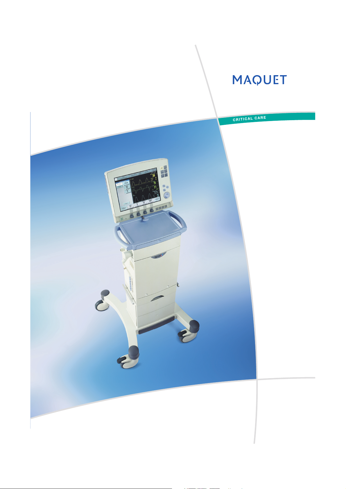
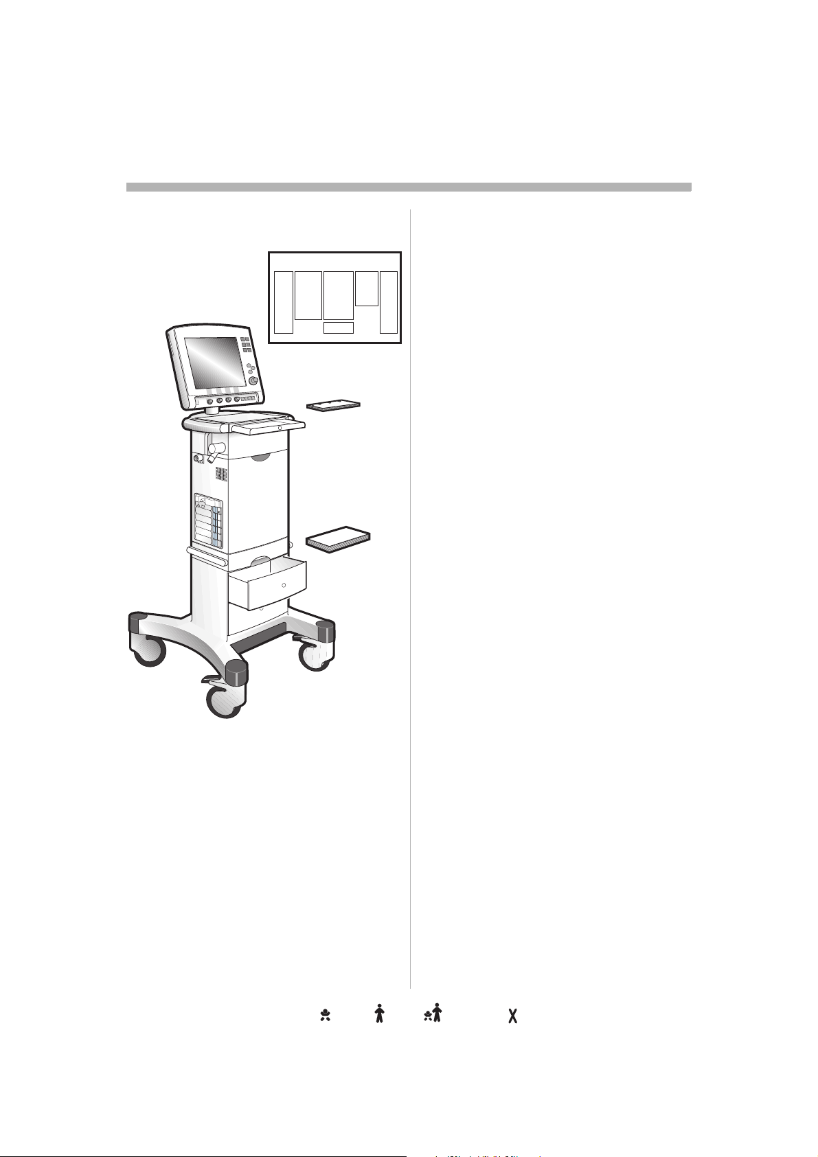
Brief device descriptionrief device descriptionief device descriptionef device descriptionf device description device descriptiondevice descriptionevice descriptionvice descriptionice descriptionce descriptione description descriptiondescriptionescriptionscriptioncriptionriptioniptionptiontioniononn
User
Interface
Patient
Patient
breathing
system
SVX-128_EN
The Servo-i Ventilator System consists of a vo-i Ventilator System consists of a
Patient Unit where gases are mixed and Unit where gases are mixed and
administered, and a User Interface where the
settings are made and ventilation is ventilation is
monitored.
The ventilator delivers controlled or
supported breaths to the patient, with either breaths to the patient, with either
constant flow or constant pressure, using a
set oxygen concentration. The entire Servo-i ygen concentration. The entire Servo-i
system includes a wide range of optional ludes a wide range of optional
accessories, e.g. Mobile Cart, breathing bile Cart, breathing
systems, compressors, Battery modules, pressors, Battery modules,
humidifiers and equipment for nebulization, quipment for nebulization,
measurement and Y-piece
COO
2
measurement.
Unit
Intended userntended usertended userended usernded userded usered userd user userusersererr
Servo-i is a ventilator system with advanced dvanced
functionality. It may be used only by
professional health care providers who have rofessional health care providers who have
sufficient experience in ventilator treatment.ment.
Intended populationntended populationtended populationended populationnded populationded populationed populationd population populationpopulationopulationpulationulationlationationtioniononn
The Servo-i Ventilator System can be can be
delivered in three configurations:
• Servo-i Infant range 0,5 - 30kg0,5 - 30kg
NIV (PC+PS) Infant range 3 - 30kg) Infant range 3 - 30kg
NIV Nasal CPAP range 0.5 - 10kgCPAP range 0.5 - 10kg
• Servo-i Adult lt range 10 - 250kg
• Servo-i Universal range 0.5 - 250kg
NIV (PC+PS) Infant range 3 - 30kge 3 - 30kg
NIV Nasal CPAP range 0.5 - 10kgrange 0.5 - 10kg
Note: Servo-i Universal covers both Basic both Basic
and Extended edition.
Warnings, Cautions and arnings, Cautions and rnings, Cautions and nings, Cautions and ings, Cautions and ngs, Cautions and gs, Cautions and s, Cautions and , Cautions and Cautions and Cautions and autions and utions and tions and ions and ons and ns and s and and and nd d
Important in this manualmportant in this manualportant in this manualortant in this manualrtant in this manualtant in this manualant in this manualnt in this manualt in this manual in this manualin this manualn this manual this manualthis manualhis manualis manuals manual manualmanualanualnualualall
WARNING! ARNING! Indicates critical information
about a potential serious outcome to the potential serious outcome to the
patient or the user.
Caution: Indicates instructions that must be must be
followed in order to ensure the proper
operation of the equipment.quipment.
Important:mportant: Indicates information intended to
help you operate the equipment or its
connected devices easily and conveniently.
Intended usentended usetended useended usended useded useed used use useusesee
The Servo-i Ventilator System is intended for he Servo-i Ventilator System is intended for
treatment and monitoring of patients in the g of patients in the
range of neonates, infants and adults with
respiratory failure or respiratory insufficiency. ciency.
Servo-i is a ventilator system to be used only
by health care providers in hospitals or health health care providers in hospitals or health
care facilities and for in-hospital transport.
Note: The Servo-i Ventilator System is not
intended to be used with any anesthetic with any anesthetic
agents.
4
Infant Adult Universal Option
Servo… User´s manual
US edition
Order No: 66 00 261
Page 7
Before useefore usefore useore usere usee use useusesee
1
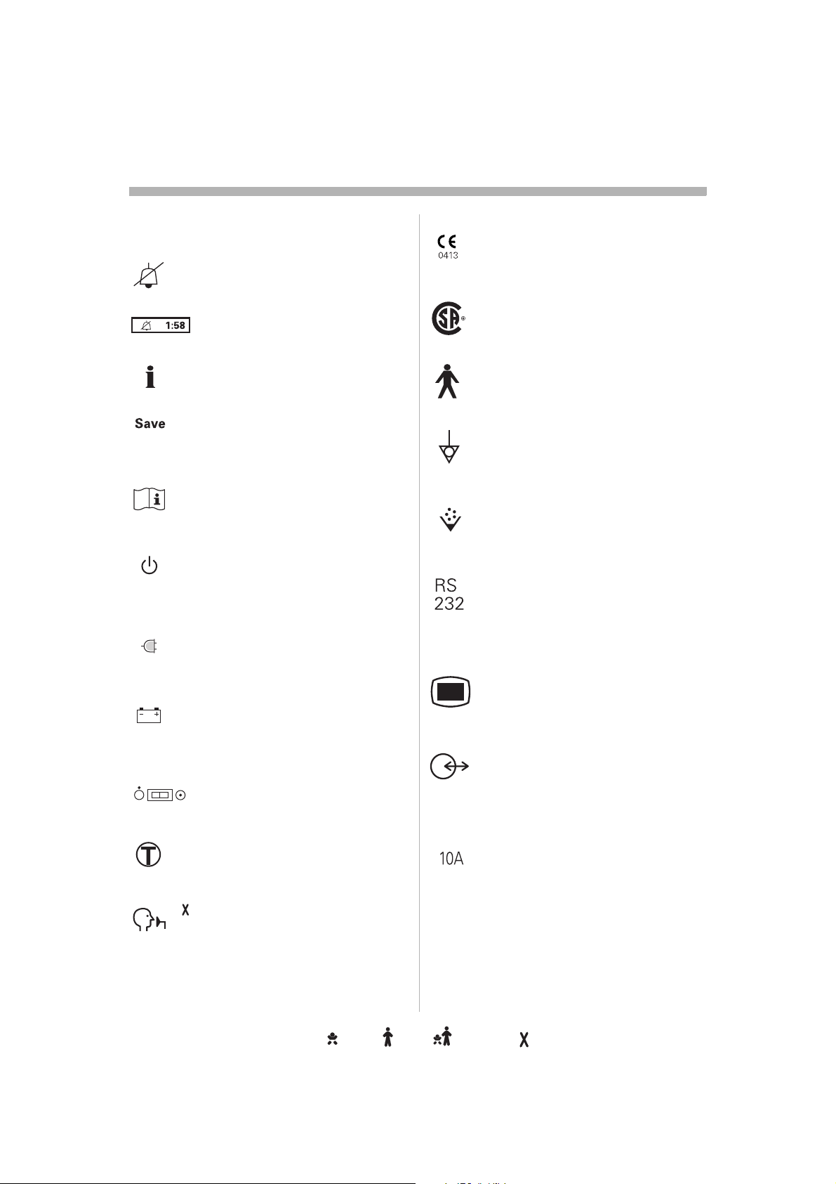
Symbolsymbolsmbolsbolsolslss
User Interfacece
Audio off Silence alarm or confirm
alarm.
Audio pause Silence alarm or
confirm alarm.
Reserved for future use.
Save To save a recording or to copy py
screen.
Attention Consult accompanying
documents.
Standby/Start ventilation Set
standby mode or start ventilation.
Yellow lamp indicating Standby g Standby
mode.
Mains indicatorcator
Green lampp indicating mains
connected.
Battery Symbol indicating battery ry
power supply.The estimated
remaining time with current power ning time with current power
consumption is indicated in minutes.
ON/OFF switch
Patient Unit
CE label The device complies with he device complies with
the requirements of the Medical f the Medical
Device Directive 93/42/EEC.42/EEC.
CSA label The device complies plies
with the Canadian standards.
C US
Class I equipment, Type Buipment, Type B The
device classification according to on according to
according to IEC 60601-1/EN 6060-1.N 6060-1.
Equipotentiality terminalality terminal
Nebulizer
connector for nebulizer.
RS 232 / Serial port232 / Serial port
connector for data communicationmmunication
Note: The symbol has two different different
labels depending on panel version.
User Interface connector / Panelser Interface connector / Panel
Note: The symbol has two different ymbol has two different
labels depending on panel version.g on panel version.
Optional connector / Expansionptional connector / Expansion
connector for optional equipment.
Note: The symbol has two different
labels depending on panel version.pending on panel version.
Trigger indicationgger indication The indication The indication
appears in the message/alarm field field
when the patient triggers a breath.
The NIV symbol appears in the NIV symbol appears in the Mode
pad field during Non Invasive d field during Non Invasive
Ventilation.
Servo… User´s manual
US edition
Order No: 66 00 261
NIV symbolmbol
10A0A
fuse for external DC power supply.C power supply.
Infant Adult Universal Options
5
Page 8
s
Before useefore usefore useore usere usee use useusesee
1
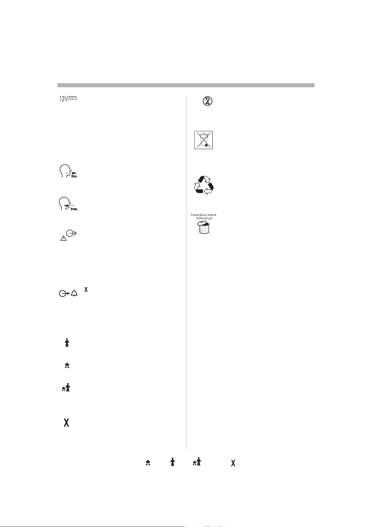
12V DC / Ext. bat 12Vat 12V
external +12V DC inlet.12V DC inlet.
Note: The symbol has two different bol has two different
labels depending on panel version.
Caution: When external +12 V DC When external +12 V DC C
is used, at least one installed
Battery module is required to ensure
proper operation.
Expiratory labelpiratory label
Gas flow from patient.
Inspiratory label
Gas flow to patient.
Gas exhaust port labelust port label
Exhaust gas flow from ventilator.haust gas flow from ventilator.
Note: Should not be connected to a d not be connected to a
spirometer, as the volume through gh
the exhaust port is not equal to the
expired volume from the patient.me from the patient.
Single use
Special waste
This product contains electronic product contains electronic
and electrical components.
Discard disposable, replaced and
left-over parts in accordance with ver parts in accordance with
appropriate industrial and
environmental standards.
Recycling
Worn-out batteries must be
recycled or disposed of properly posed of properly
in accordance with appropriate
industrial and environmental mental
standards.
Hazardous wastes waste (infectious) The
device contains parts which must vice contains parts which must
not be disposed of with ordinary disposed of with ordinary
waste.
Alarm output connection nnection
option
External alarm output
communication.
In this manualmanual
Adult Information valid for the Adult d for the Adult
configuration
Infant Information valid for the Infant
configuration
Universal (Basic and Extended rsal (Basic and Extended
editions) Information valid for the
Universal configuration.
Options
6
Infant Adult Universal Option
Servo… User´s manual
US edition
Order No: 66 00 261
Page 9
Warnings, cautions and importantarnings, cautions and importantrnings, cautions and importantnings, cautions and importantings, cautions and importantngs, cautions and importantgs, cautions and importants, cautions and important, cautions and important cautions and importantcautions and importantautions and importantutions and importanttions and importantions and importantons and importantns and importants and important and importantand importantnd importantd important importantimportantmportantportantortantrtanttantantntt
1
Support material related to upport material related to pport material related to port material related to ort material related to rt material related to t material related to material related to material related to aterial related to terial related to erial related to rial related to ial related to al related to l related to related to related to elated to lated to ated to ted to ed to d to to to o
the Servohe Servoe Servo ServoServoervorvovoo-i systemsystemystemstemtememm
Wall cleaning diagram
Configuration Card
User‘s manual
This concept comprises components concept comprises components
intended to cover the needs of a clinical user.
It is divided into different components
according to use to facilitate accessibility of g to use to facilitate accessibility of
information. If you have any comments or ve any comments or
suggestions regarding this information
material, please let us know.please let us know.
This User´s manual covers functionality and manual covers functionality and
use but should not be regarded as all garded as all
inclusive within the very complex field of mplex field of
ventilatory treatment. Clinical judgements or judgements or
settings are therefore not described in this
manual. Authorized, medically competent Authorized, medically competent
health care providers with good knowledge viders with good knowledge
of Servo-i Ventilator System have the Ventilator System have the
responsibility to determine the clinical bility to determine the clinical
judgement and settings based on the needs settings based on the needs
of the patient.
Read the User´s manual carefully before use ´s manual carefully before use
and follow the instructions.he instructions.
SVX-129_EN
Servo… User´s manual
US edition
Order No: 66 00 261
Infant Adult Universal Options
7
Page 10

s
Warnings, cautions and importantarnings, cautions and importantrnings, cautions and importantnings, cautions and importantings, cautions and importantngs, cautions and importantgs, cautions and importants, cautions and important, cautions and important cautions and importantcautions and importantautions and importantutions and importanttions and importantions and importantons and importantns and importants and important and importantand importantnd importantd important importantimportantmportantportantortantrtanttantantntt
1
This User´s manualer´s manual
The information in this User´s manual is valid valid
for Servo-i Ventilator System 3.0 unless 3.0 unless
stated otherwise.
Here you will find the information needed to find the information needed to
use the Servo-i system safely.
It is divided into five main sections: ctions:
• Before use (mandatory information)
• Description
• Operation
• Maintenance
• Miscellaneous
Recommended use
The main document, for every-day use.
Text shown on the User Interface is presented xt shown on the User Interface is presented
in these instructions in a uctions in a special typefacel typeface.
Brief instructionsctions
Overviews and step-by-step instructions for y-step instructions for
the set-ups. These instructions you will find
in the drawer above the ventilator, when awer above the ventilator, when
positioned on the Mobile Cart.Cart.
Recommended usese
These documents are intended to be used as
a guide for the experienced user.guide for the experienced user.
Wall diagramgram
Overviews and step-by-step instructions for verviews and step-by-step instructions for
cleaning, to be posted on a wall.leaning, to be posted on a wall.
Recommended use
Checklist for the experienced user.klist for the experienced user.
Ventilator - Information entilator - Information ntilator - Information tilator - Information ilator - Information lator - Information ator - Information tor - Information or - Information r - Information - Information - Information Information Information nformation formation ormation rmation mation ation tion ion on n
materialaterialterialerialrialialall
Caution: The Servo-i Ventilator System may Servo-i Ventilator System may
have different software versions. ware versions. Before use,
make sure the software version shown on the
screen under the der the Status / General General menu
corresponds to the version number on the
User´s manual.anual. Refer to page 259.
Trademarkrademarkademarkdemarkemarkmarkarkrkk
Trademark ™demark ™ is written only when a product/product/
method name appears for the first time in this
manual.
8
Infant Adult Universal Option
Servo… User´s manual
US edition
Order No: 66 00 261
Page 11

Warnings, cautions and importantarnings, cautions and importantrnings, cautions and importantnings, cautions and importantings, cautions and importantngs, cautions and importantgs, cautions and importants, cautions and important, cautions and important cautions and importantcautions and importantautions and importantutions and importanttions and importantions and importantons and importantns and importants and important and importantand importantnd importantd important importantimportantmportantportantortantrtanttantantntt
1
General warningseneral warningsneral warningseral warningsral warningsal warningsl warnings warningswarningsarningsrningsningsingsngsgss
• The Servo-i Ventilator System must be ust be
operated only by authorized personnel
who are well trained in its use. It must be must be
operated according to the instructions in
this User´s manual.User´s manual.
• After unpacking, perform a Routine g, perform a Routine
cleaning and a Pre-use check.se check.
• To provide adequate patient safety, set the nt safety, set the
alarm limits to relevant values.
• To avoid electrical shock hazard, connect ctrical shock hazard, connect
the power cord to a mains outlet equipped utlet equipped
with a protective ground.
• Should any unfamiliar events occur, such ccur, such
as irrelevant pop-up windows on the
screen, unfamiliar sounds, alarms from the miliar sounds, alarms from the
Patient Unit or technical high priority gh priority
alarms, the ventilator should immediately
be checked and, if applicable, replaced.
• Only accessories and auxiliary equipment ories and auxiliary equipment
that meet current IEC standards (e.g. IEC current IEC standards (e.g. IEC
60601-1-1) may be connected to the 1-1-1) may be connected to the
Servo-i Ventilator System. If external vo-i Ventilator System. If external
equipment such as computers, monitors, quipment such as computers, monitors,
humidifiers or printers are connected, the
total system must comply with IEC 60601-ystem must comply with IEC 60601-606011-1.
• The ventilator must only be used in an y be used in an
upright position.
• When a Servo Ultra Nebulizer is used, ulizer is used,
always consult the drug manufacturer manufacturer
regarding the appropriateness of
ultrasonic nebulization for certain bulization for certain
medication.
• All personnel should be aware of the risk sonnel should be aware of the risk
of parts being infected when g infected when
disassembling and cleaning the ventilator.r.
• Service mode may only be used when no when no
patient is connected to the ventilator.
• Positive pressure ventilation can be be
associated with the following adverse
events: barotrauma, hypoventilation, ma, hypoventilation,
hyperventilation or circulatory impairment.
• The Servo-i Ventilator System is verified Servo-i Ventilator System is verified
against and complies with IEC 60601-1-2 gainst and complies with IEC 60601-1-2 C 60601-1-2
regarding electromagnetic compatibility. It magnetic compatibility. It
is the responsibility of the user to take user to take
necessary measures to ensure that the
clinical environment is compatible with the ble with the
limits specified in IEC 60601-1-2. C 60601-1-2.
Exceeding of these limits may impair the these limits may impair the
performance and safety of the system.
Such measures should include, but are not uch measures should include, but are not
limited to:
– Normal precautions with regard to precautions with regard to
relative humidity and conductive midity and conductive
characteristics of clothing in order to
minimize the build-up of electrostatic ze the build-up of electrostatic
charges.
– Avoiding the use of radio-emitting
devices, such as cellular phones and ces, such as cellular phones and
high-frequency apparatus in close tus in close
proximity to the system.
• The Servo-i Ventilator System is not Servo-i Ventilator System is not
intended to be used in MR environment used in MR environment
during MR examinations. This may cause This may cause
deactivation of the system functions and
may result in permanent damage to the permanent damage to the
Servo-i Ventilator System.ystem.
• The Servo-i Ventilator System is not
intended to be used with any anesthetic ded to be used with any anesthetic
agent. To avoid risk of fire, flammable To avoid risk of fire, flammable
agents such as ether and cyclopropane uch as ether and cyclopropane
must not under any circumstances be
used with this device.with this device.
Servo… User´s manual
US edition
Order No: 66 00 261
Infant Adult Universal Options
9
Page 12

s
Warnings, cautions and importantarnings, cautions and importantrnings, cautions and importantnings, cautions and importantings, cautions and importantngs, cautions and importantgs, cautions and importants, cautions and important, cautions and important cautions and importantcautions and importantautions and importantutions and importanttions and importantions and importantons and importantns and importants and important and importantand importantnd importantd important importantimportantmportantportantortantrtanttantantntt
1
• To avoid fire hazard, keep all sources of zard, keep all sources of
ignition away from the y from the Servo-i Ventilator
System and oxygen hoses. Do not use xygen hoses. Do not use
oxygen hoses that are worn, frayed, or d, or
contaminated by combustible materials
such as grease or oils. Textiles, oils, and Textiles, oils, and
other combustibles are easily ignited and y ignited and
burn with great intensity in air enriched
with oxygen. Immediately disconnect the xygen. Immediately disconnect the
ventilator from the oxygen supply, facility from the oxygen supply, facility
power, and backup sources if there is a wer, and backup sources if there is a
smell of burning.mell of burning.
General cautionseneral cautionsneral cautionseral cautionsral cautionsal cautionsl cautions cautionscautionsautionsutionstionsionsonsnss
• As a general rule always avoid contact void contact
with external electrical connector pins. It is
recommended to have the module ule
compartment filled up with empty modules s
to protect from spillage and dust.
• Federal law in the USA restricts this device w in the USA restricts this device
to sale by or on the order of a physician (or ale by or on the order of a physician (or
a properly licensed practitioner).
• The Servo-i Ventilator System must be ust be
serviced at regular intervals by specially
trained personnel. The intervals are stated The intervals are stated
in the chapter Regular maintenance. Any maintenance. Any
maintenance must be noted in a log book k
for that purpose in accordance with
national regulations.gulations.
• MAQUET has no responsibility for the safe T has no responsibility for the safe
operation of the equipment if service or ment if service or
repair is done by a non-professional or by
persons who are not employed by or who are not employed by or
authorized by MAQUET. We recommend MAQUET. We recommend mmend
that service is done as part of a service
contract with MAQUET.MAQUET.
• MAQUET has no responsibility for the safe esponsibility for the safe
operation of the equipment if the
equipment is used for anything other than d for anything other than
its intended use, as specified in this User´s User´s
manual.
• A resuscitator should always be readily ways be readily
accessible for extra safety.
• When connected to a patient, the system hen connected to a patient, the system
must never be left unattended. be left unattended.
• The nebulizer module is inoperative when perative when
the ventilator is running on batteries, to
reduce the power consumption.ce the power consumption.
• The Expiratory cassette must not be lifted atory cassette must not be lifted
up when the ventilator is in operation. This when the ventilator is in operation. This
may, however, be done when in Standby be done when in Standby
mode.
• Always use heat and moisture exchanger lways use heat and moisture exchanger ger
(HME) or equipment to prevent t to prevent
dehydration of lung tissue.
• Refer to the Installation instructions to
assemble the system or options to obtain ptions to obtain
a proper mechanical assembly.
• When lifting or moving the ventilator
system or parts of the system, follow parts of the system, follow
established ergonomic guidelines, ask for gonomic guidelines, ask for
assistance, and take appropriate safety y
precautions.
• Antistatic or electrically conductive
breathing tubing should not be used with
this lung ventilator system.m.
• Any scavenging system (Gas evac)
connected must comply to ISO8835-3 onnected must comply to ISO8835-3 8835-3
with regard to subatmospheric pressure mospheric pressure
and induced flow. Otherwise ventilator Otherwise ventilator
functions and patient safety may be patient safety may be
degraded.
• It is not recommended to use the Servo commended to use the Servo
Evac 180 in the Nasal CPAP mode.80 in the Nasal CPAP mode.ode.
• Values measured at the signal outputs of f
the Servo-i Ventilator System and which which
have been processed in auxiliary y
equipment must not be used as a
substitute for therapeutic or diagnostic herapeutic or diagnostic
decisions. Such decisions can be made made
only by staff with medical expertise, pertise,
according to established and accepted
practice. If auxiliary equipment that has xiliary equipment that has
not been delivered by MAQUET with the delivered by MAQUET with the T with the
system is used, MAQUET denies all QUET denies all
responsibility for the accuracy of signal ty for the accuracy of signal
processing.
10
Servo… User´s manual
Infant Adult Universal Option
US edition
Order No: 66 00 261
Page 13

Warnings, cautions and importantarnings, cautions and importantrnings, cautions and importantnings, cautions and importantings, cautions and importantngs, cautions and importantgs, cautions and importants, cautions and important, cautions and important cautions and importantcautions and importantautions and importantutions and importanttions and importantions and importantons and importantns and importants and important and importantand importantnd importantd important importantimportantmportantportantortantrtanttantantntt
1
• If there should be any deviation between d be any deviation between
information shown on the User Interface of User Interface of
the ventilator and that shown by the y the
auxiliary equipment, the ventilator
parameters shown on the User Interface wn on the User Interface
shall be considered the primary source for mary source for
information. When combining the g the Servo-i
Ventilator System with accessories and with accessories and
auxiliary equipment other than those pment other than those
recommended by MAQUET, it is the AQUET, it is the
responsibility of the user to ensure the bility of the user to ensure the
integrity of system performance and ce and
safety. In order to maintain electrical
system safety, i.e. such that compliance
with IEC 60601-1-1 is fulfilled, only nly
accessories and auxiliary equipment that hat
meet current IEC standards (e.g. IEC
60601-1, IEC 950) may be connected to connected to
signal inputs and outputs of the Servo-i -i
Ventilator System.
• Only original parts from MAQUET must be parts from MAQUET must be T must be
used in the system.
• Only accessories, supplies or auxiliary ccessories, supplies or auxiliary
equipment recommended by MAQUET by MAQUET
should be used with the ventilator system ld be used with the ventilator system
(“Products and accessories” catalog and
“Spare parts list”). Use of any other ). Use of any other
accessories, spare parts or auxiliary
equipment may cause degraded system quipment may cause degraded system
performance and safety. ormance and safety.
• The displayed information about set and layed information about set and
corresponding measured parameters, g measured parameters,
shall continously be compared by the be compared by the
operator.
Important:
• This symbol on the unit means n the unit means
Attention, consult accompanying
documents.
Note: The are two versions of this symbol ymbol
depending on System version.
• The gases supplied must be free from
water, oil and particles:
Air ................... H
O < 7 g/m
2
........................ Oil < 0.5 mg/m
Oxygen ........... H2O < 20 mg/m20 mg/m
3
3
3
• The environmental declaration is part of declaration is part of
the service manual.
• The Servo-i Ventilator system does not does not
contain any latex.
• Data on pressures can be given in cmHgiven in cmH
where:
1 kPa ~ 10 cmHPa ~ 10 cmH
100 kPa = 1bar ~1atm ~1kgf/cm/cm
O
2
2
(kp/cm2)
100 kPa ~15 psi.
• All disposable parts must be discarded
according to hospital routine and in an hospital routine and in an
environmentally safe way.way.
• Do not expose the Expiratory cassette cassette
compartment to excessive amounts of
fluid, e.g. during cleaning and disinfection,
as this may influence ventilator his may influence ventilator
functionality.
• Do not use sharp tools on the screen.p tools on the screen.
• It is recommended that at least two
batteries always is used in the ventilator for ys is used in the ventilator for
backup.p.
• It is recommended that at least two
batteries are used for ventilation during used for ventilation during
transport.
2
O,
Servo… User´s manual
US edition
Order No: 66 00 261
Infant Adult Universal Options
11
Page 14

s
Warnings, cautions and importantarnings, cautions and importantrnings, cautions and importantnings, cautions and importantings, cautions and importantngs, cautions and importantgs, cautions and importants, cautions and important, cautions and important cautions and importantcautions and importantautions and importantutions and importanttions and importantions and importantons and importantns and importants and important and importantand importantnd importantd important importantimportantmportantportantortantrtanttantantntt
1
• Documentation for Servo-i Ventilator
System stem consists of:
–User´s manual
– Brief instructions
– Wall diagramdiagram
– Installation instructions
– Service manual
– Products and accessories, catalog, catalog
– Spare parts list
Context-related warnings ontext-related warnings ntext-related warnings text-related warnings ext-related warnings xt-related warnings t-related warnings -related warnings related warnings elated warnings lated warnings ated warnings ted warnings ed warnings d warnings warnings warnings arnings rnings nings ings ngs gs s
Note: General warnings are not listed here here
even though they are repeated inside the
manual.
Note: Context-related Cautions and
"Important" are not listed here, but are but are
written in the relevant context inside the
manual.
Operationperationerationrationationtioniononn
• Always disconnect the ventilator if any ventilator if any
operation which may involve risk for the k for the
patient will be done, e.g. replacement of ment of
cell, dismantling etc. (page 211, 211,
O
2
page 225).
• If the trigger sensitivity is set too high, a y is set too high, a
self-triggering (auto-triggering) condition
may be reached. This condition can also
be reached if there is leakage in the kage in the
breathing system, e.g. if an uncuffed d
endotracheal tube is used. Triggering will
then be initiated by the system and not by y the system and not by
the patient.This should always be avoided ways be avoided
by decreasing the trigger sensitivity
(page 23). This is also important during page 23). This is also important during during
transport as the movement of the body y
and the breathing system may lead to
false triggering.
• When you turn a Direct Access Knob, Knob,
ventilation will change accordingly from y from
the next breath without additional
confirmation (For further information see
page 166).166).
• If any malfunctions are detected during the detected during the
start-up procedure, please refer to
Chapter, Troubleshooting (page 225).Troubleshooting (page 225).5).
• If a malfunction persists, the ventilator ventilator
may not be connected to the patient.
• A Pre-use check must always be done be done
before connecting the ventilator to a
patient (page 145).45).
• To protect the patient against high airway way
pressures, the upper pressure limit must
always be set to the relevant value so as to
provide adequate patient safety (page de adequate patient safety (page
165). 5).
Caution: If airway pressure rises 6 cmHH
above the set upper pressure limit the
safety valve opens. The safety valve also fety valve opens. The safety valve also
opens if system pressure exceeds 117 xceeds 117
cmH
O.
2
• To provide adequate patient safety, always rovide adequate patient safety, always
set the alarm limits at relevant values he alarm limits at relevant values
(page 165).).
O
2
± 7
12
Servo… User´s manual
Infant Adult Universal Option
US edition
Order No: 66 00 261
Page 15

Warnings, cautions and importantarnings, cautions and importantrnings, cautions and importantnings, cautions and importantings, cautions and importantngs, cautions and importantgs, cautions and importants, cautions and important, cautions and important cautions and importantcautions and importantautions and importantutions and importanttions and importantions and importantons and importantns and importants and important and importantand importantnd importantd important importantimportantmportantportantortantrtanttantantntt
1
Nebulizationebulizationbulizationulizationlizationizationzationationtioniononn
• Servo Humidifier/HME must be ME must be
disconnected during nebulization ation
otherwise the humidifier may be blocked cked
(page 128).
• The heated humidifier must be switched ted humidifier must be switched
off during nebulization. Otherwise the zation. Otherwise the
particle size may be affected (page 128).y be affected (page 128).
• During nebulization a filter must be
connected to the expiratory inlet of the d to the expiratory inlet of the
ventilator. Always carefully monitor the s carefully monitor the
airway pressure during nebulization. during nebulization.
Increased airway pressure could be pressure could be
caused by a clogged filter. The filter should he filter should
be replaced if the expiratory resistance
increases or every 24 hours when the very 24 hours when the
nebulizer is being used.g used.
• When a Servo Ultra Nebulizer is used, Ultra Nebulizer is used,
always consult the drug manufacturer onsult the drug manufacturer
regarding the appropriateness of
ultrasonic nebulization for certain bulization for certain
medications (page 128, 187).ge 128, 187).
• The nebulizer must not be used without must not be used without
buffer liquid (sterile water). Otherwise the ater). Otherwise the
ultrasonic generator crystal may break may break
(page 129, 187).7).
• To avoid explosion hazards, flammable flammable
agents such as ether and cyclopropane propane
must not be used with this device. Only ce. Only
agents which comply with the ply with the
requirements on non-flammable agents in ble agents in
the IEC standard “Particular requirements ular requirements
for electrical safety of anaesthetic
machines” are suitable.
• For adult/pediatric patients, never fill the
medication cup with more than 10 ml
(page 129).
• For neonatal patients, never fill the ver fill the
medication cup with more than 4 ml 4 ml
(page 129).
• If the patient unit of the nebulizer is tilted, nt unit of the nebulizer is tilted,
the drug can flow into the patient´s lungs patient´s lungs
or the ventilator.
• The nebulizer must not be left unattended must not be left unattended
when connected to a patient.
• Continuously check that the buffer liquid quid
level is between MIN. and MAX. during AX. during
nebulization (page 187).page 187).
• During nebulization: Continuously check on: Continuously check
that moisture is generated in the d in the
medication cup (page 187).7).
• When the ventilator is running on batteries batteries
the nebulizer module is inoperative, to
reduce the power consumption ce the power consumption
(page 187).87).
• For information about the stand alone stand alone
Aeroneb Professional Nebulizer System, System,
refer to separate manual.
Cleaningleaningeaninganingningingngg
• All personnel should be aware of the risk hould be aware of the risk
of parts being infected when g infected when
disassembling and cleaning the ventilator r
(page 191).
• After removing the Expiratory cassette, do ng the Expiratory cassette, do
not pour any fluid into the Expiratory ur any fluid into the Expiratory
cassette compartment (page 196).mpartment (page 196).
Replacement of Oeplacement of Oplacement of Olacement of Oacement of Ocement of Oement of Oment of Oent of Ont of Ot of O of Oof Of O OO2 cellcellelllll
The sealed unit of the O2 cell, contains a led unit of the O2 cell, contains a
caustic liquid which may cause severe burns which may cause severe burns
to the skin and eyes. In case of contact, kin and eyes. In case of contact,
immediately flush continuously with water for with water for
at least 15 minutes and seek medical cal
attention especially if the eyes are affected
(page 214)14)
Servo… User´s manual
US edition
Order No: 66 00 261
Infant Adult Universal Options
13
Page 16

1
s
Notesotestesess
..................................................................
..................................................................
..................................................................
..................................................................
..................................................................
..................................................................
..................................................................
..................................................................
..................................................................
..................................................................
..................................................................
..................................................................
..................................................................
..................................................................
..................................................................
..................................................................
..................................................................
..................................................................
..................................................................
..................................................................
..................................................................
..................................................................
..................................................................
..................................................................
14
Infant Adult Universal Option
..................................................................
..................................................................
..................................................................
..................................................................
..................................................................
..................................................................
Servo… User´s manual
US edition
Order No: 66 00 261
Page 17

2.. Ventilationentilationntilationtilationilationlationationtioniononn
Contentsontentsntentstentsentsntstss
Modes of ventilationodes of ventilationdes of ventilationes of ventilations of ventilation of ventilationof ventilationf ventilation ventilationventilationentilationntilationtilationilationlationationtioniononn. . . . . . . . . . . . . . . . . . . . . . . . . . . . . . . . . . . . . . . . . . . . .. . . . . . . . . . . . . . . . . . . . . . . . . . . . . . . . . . . . . . . . . . .. . . . . . . . . . . . . . . . . . . . . . . . . . . . . . . . . . . . . . . . .. . . . . . . . . . . . . . . . . . . . . . . . . . . . . . . . . . . . . . .. . . . . . . . . . . . . . . . . . . . . . . . . . . . . . . . . . . . .. . . . . . . . . . . . . . . . . . . . . . . . . . . . . . . . . . .. . . . . . . . . . . . . . . . . . . . . . . . . . . . . . . . .. . . . . . . . . . . . . . . . . . . . . . . . . . . . . . .. . . . . . . . . . . . . . . . . . . . . . . . . . . . .. . . . . . . . . . . . . . . . . . . . . . . . . . .. . . . . . . . . . . . . . . . . . . . . . . . .. . . . . . . . . . . . . . . . . . . . . . .. . . . . . . . . . . . . . . . . . . . .. . . . . . . . . . . . . . . . . . .. . . . . . . . . . . . . . . . .. . . . . . . . . . . . . . .. . . . . . . . . . . . .. . . . . . . . . . .. . . . . . . . .. . . . . . .. . . . .. . .. 16166
Important definitionsmportant definitionsportant definitionsortant definitionsrtant definitionstant definitionsant definitionsnt definitionst definitions definitionsdefinitionsefinitionsfinitionsinitionsnitionsitionstionsionsonsnss . . . . . . . . . . . . . . . . . . . . . .. . . . . . . . . . . . . . . . . . . . . . . . . . . . . . . . . . . . . . . . . . .. . . . . . . . . . . . . . . . . . . . . . . . . . . . . . . . . . . . . . . . .. . . . . . . . . . . . . . . . . . . . . . . . . . . . . . . . . . . . . . .. . . . . . . . . . . . . . . . . . . . . . . . . . . . . . . . . . . . .. . . . . . . . . . . . . . . . . . . . . . . . . . . . . . . . . . .. . . . . . . . . . . . . . . . . . . . . . . . . . . . . . . . .. . . . . . . . . . . . . . . . . . . . . . . . . . . . . . .. . . . . . . . . . . . . . . . . . . . . . . . . . . . .. . . . . . . . . . . . . . . . . . . . . . . . . . .. . . . . . . . . . . . . . . . . . . . . . . . .. . . . . . . . . . . . . . . . . . . . . . .. . . . . . . . . . . . . . . . . . . . .. . . . . . . . . . . . . . . . . . .. . . . . . . . . . . . . . . . .. . . . . . . . . . . . . . .. . . . . . . . . . . . .. . . . . . . . . . .. . . . . . . . .. . . . . . .. . . . .. . .. 21211
Trigger sensitivityrigger sensitivityigger sensitivitygger sensitivityger sensitivityer sensitivityr sensitivity sensitivitysensitivityensitivitynsitivitysitivityitivitytivityivityvityitytyy . . . . . . . . . . . . . . . . . . . . . . . . .. . . . . . . . . . . . . . . . . . . . . . . . . . . . . . . . . . . . . . . . . . . . . . . . .. . . . . . . . . . . . . . . . . . . . . . . . . . . . . . . . . . . . . . . . . . . . . . .. . . . . . . . . . . . . . . . . . . . . . . . . . . . . . . . . . . . . . . . . . . . .. . . . . . . . . . . . . . . . . . . . . . . . . . . . . . . . . . . . . . . . . . .. . . . . . . . . . . . . . . . . . . . . . . . . . . . . . . . . . . . . . . . .. . . . . . . . . . . . . . . . . . . . . . . . . . . . . . . . . . . . . . .. . . . . . . . . . . . . . . . . . . . . . . . . . . . . . . . . . . . .. . . . . . . . . . . . . . . . . . . . . . . . . . . . . . . . . . .. . . . . . . . . . . . . . . . . . . . . . . . . . . . . . . . .. . . . . . . . . . . . . . . . . . . . . . . . . . . . . . .. . . . . . . . . . . . . . . . . . . . . . . . . . . . .. . . . . . . . . . . . . . . . . . . . . . . . . . .. . . . . . . . . . . . . . . . . . . . . . . . .. . . . . . . . . . . . . . . . . . . . . . .. . . . . . . . . . . . . . . . . . . . .. . . . . . . . . . . . . . . . . . .. . . . . . . . . . . . . . . . .. . . . . . . . . . . . . . .. . . . . . . . . . . . .. . . . . . . . . . .. . . . . . . . .. . . . . . .. . . . .. . .. 23233
Settingsettingsttingstingsingsngsgss . . . . . . . . . . . . . . . . . . . . . . . . . . . . . . . .. . . . . . . . . . . . . . . . . . . . . . . . . . . . . . . . . . . . . . . . . . . . . . . . . . . . . . . . . . . . . . .. . . . . . . . . . . . . . . . . . . . . . . . . . . . . . . . . . . . . . . . . . . . . . . . . . . . . . . . . . . . .. . . . . . . . . . . . . . . . . . . . . . . . . . . . . . . . . . . . . . . . . . . . . . . . . . . . . . . . . . .. . . . . . . . . . . . . . . . . . . . . . . . . . . . . . . . . . . . . . . . . . . . . . . . . . . . . . . . .. . . . . . . . . . . . . . . . . . . . . . . . . . . . . . . . . . . . . . . . . . . . . . . . . . . . . . .. . . . . . . . . . . . . . . . . . . . . . . . . . . . . . . . . . . . . . . . . . . . . . . . . . . . .. . . . . . . . . . . . . . . . . . . . . . . . . . . . . . . . . . . . . . . . . . . . . . . . . . .. . . . . . . . . . . . . . . . . . . . . . . . . . . . . . . . . . . . . . . . . . . . . . . . .. . . . . . . . . . . . . . . . . . . . . . . . . . . . . . . . . . . . . . . . . . . . . . .. . . . . . . . . . . . . . . . . . . . . . . . . . . . . . . . . . . . . . . . . . . . .. . . . . . . . . . . . . . . . . . . . . . . . . . . . . . . . . . . . . . . . . . .. . . . . . . . . . . . . . . . . . . . . . . . . . . . . . . . . . . . . . . . .. . . . . . . . . . . . . . . . . . . . . . . . . . . . . . . . . . . . . . .. . . . . . . . . . . . . . . . . . . . . . . . . . . . . . . . . . . . .. . . . . . . . . . . . . . . . . . . . . . . . . . . . . . . . . . .. . . . . . . . . . . . . . . . . . . . . . . . . . . . . . . . .. . . . . . . . . . . . . . . . . . . . . . . . . . . . . . .. . . . . . . . . . . . . . . . . . . . . . . . . . . . .. . . . . . . . . . . . . . . . . . . . . . . . . . .. . . . . . . . . . . . . . . . . . . . . . . . .. . . . . . . . . . . . . . . . . . . . . . .. . . . . . . . . . . . . . . . . . . . .. . . . . . . . . . . . . . . . . . .. . . . . . . . . . . . . . . . .. . . . . . . . . . . . . . .. . . . . . . . . . . . .. . . . . . . . . . .. . . . . . . . .. . . . . . .. . . . .. . .. 25255
Special functionspecial functionsecial functionscial functionsial functionsal functionsl functions functionsfunctionsunctionsnctionsctionstionsionsonsnss . . . . . . . . . . . . . . . . . . . . . . . . .. . . . . . . . . . . . . . . . . . . . . . . . . . . . . . . . . . . . . . . . . . . . . . . . .. . . . . . . . . . . . . . . . . . . . . . . . . . . . . . . . . . . . . . . . . . . . . . .. . . . . . . . . . . . . . . . . . . . . . . . . . . . . . . . . . . . . . . . . . . . .. . . . . . . . . . . . . . . . . . . . . . . . . . . . . . . . . . . . . . . . . . .. . . . . . . . . . . . . . . . . . . . . . . . . . . . . . . . . . . . . . . . .. . . . . . . . . . . . . . . . . . . . . . . . . . . . . . . . . . . . . . .. . . . . . . . . . . . . . . . . . . . . . . . . . . . . . . . . . . . .. . . . . . . . . . . . . . . . . . . . . . . . . . . . . . . . . . .. . . . . . . . . . . . . . . . . . . . . . . . . . . . . . . . .. . . . . . . . . . . . . . . . . . . . . . . . . . . . . . .. . . . . . . . . . . . . . . . . . . . . . . . . . . . .. . . . . . . . . . . . . . . . . . . . . . . . . . .. . . . . . . . . . . . . . . . . . . . . . . . .. . . . . . . . . . . . . . . . . . . . . . .. . . . . . . . . . . . . . . . . . . . .. . . . . . . . . . . . . . . . . . .. . . . . . . . . . . . . . . . .. . . . . . . . . . . . . . .. . . . . . . . . . . . .. . . . . . . . . . .. . . . . . . . .. . . . . . .. . . . .. . .. 29299
Controlled ventilation - PRVControlled ventilation - PRVCntrolled ventilation - PRVCtrolled ventilation - PRVCrolled ventilation - PRVColled ventilation - PRVClled ventilation - PRVCled ventilation - PRVCed ventilation - PRVCd ventilation - PRVC ventilation - PRVCventilation - PRVCentilation - PRVCntilation - PRVCtilation - PRVCilation - PRVClation - PRVCation - PRVCtion - PRVCion - PRVCon - PRVCn - PRVC - PRVC- PRVC PRVCPRVCRVCVCC . . . . . . . . . . . . . . .. . . . . . . . . . . . . . . . . . . . . . . . . . . . .. . . . . . . . . . . . . . . . . . . . . . . . . . .. . . . . . . . . . . . . . . . . . . . . . . . .. . . . . . . . . . . . . . . . . . . . . . .. . . . . . . . . . . . . . . . . . . . .. . . . . . . . . . . . . . . . . . .. . . . . . . . . . . . . . . . .. . . . . . . . . . . . . . .. . . . . . . . . . . . .. . . . . . . . . . .. . . . . . . . .. . . . . . .. . . . .. . .. 32322
Controlled ventilation - Volume Controlontrolled ventilation - Volume Controlntrolled ventilation - Volume Controltrolled ventilation - Volume Controlrolled ventilation - Volume Contrololled ventilation - Volume Controllled ventilation - Volume Controlled ventilation - Volume Controled ventilation - Volume Controld ventilation - Volume Control ventilation - Volume Controlventilation - Volume Controlentilation - Volume Controlntilation - Volume Controltilation - Volume Controlilation - Volume Controllation - Volume Controlation - Volume Controltion - Volume Controlion - Volume Controlon - Volume Controln - Volume Control - Volume Control- Volume Control Volume ControlVolume Contrololume Controllume Controlume Controlme Controle Control ControlControlontrolntroltrolrololl . . . . . . . . . . . . . . .. . . . . . . . . . . . .. . . . . . . . . . .. . . . . . . . .. . . . . . .. . . . .. . .. 35355
Controlled ventilation - Pressure Controlontrolled ventilation - Pressure Controlntrolled ventilation - Pressure Controltrolled ventilation - Pressure Controlrolled ventilation - Pressure Contrololled ventilation - Pressure Controllled ventilation - Pressure Controlled ventilation - Pressure Controled ventilation - Pressure Controld ventilation - Pressure Control ventilation - Pressure Controlventilation - Pressure Controlentilation - Pressure Controlntilation - Pressure Controltilation - Pressure Controlilation - Pressure Controllation - Pressure Controlation - Pressure Controltion - Pressure Controlion - Pressure Controlon - Pressure Controln - Pressure Control - Pressure Control- Pressure Control Pressure ControlPressure Controlressure Controlessure Controlssure Controlsure Controlure Controlre Controle Control ControlControlontrolntroltrolrololl . . . . . . . . . . . . .. . . . . . . . . . .. . . . . . . . .. . . . . . .. . . . .. . .. 38388
Supported ventilation - Volume Supportupported ventilation - Volume Supportpported ventilation - Volume Supportported ventilation - Volume Supportorted ventilation - Volume Supportrted ventilation - Volume Supportted ventilation - Volume Supported ventilation - Volume Supportd ventilation - Volume Support ventilation - Volume Supportventilation - Volume Supportentilation - Volume Supportntilation - Volume Supporttilation - Volume Supportilation - Volume Supportlation - Volume Supportation - Volume Supporttion - Volume Supportion - Volume Supporton - Volume Supportn - Volume Support - Volume Support- Volume Support Volume SupportVolume Supportolume Supportlume Supportume Supportme Supporte Support SupportSupportupportpportportortrtt . . . . . . .. . . . . . . . . . . . .. . . . . . . . . . .. . . . . . . . .. . . . . . .. . . . .. . .. 40400
Supported ventilation - Pressure Supportupported ventilation - Pressure Supportpported ventilation - Pressure Supportported ventilation - Pressure Supportorted ventilation - Pressure Supportrted ventilation - Pressure Supportted ventilation - Pressure Supported ventilation - Pressure Supportd ventilation - Pressure Support ventilation - Pressure Supportventilation - Pressure Supportentilation - Pressure Supportntilation - Pressure Supporttilation - Pressure Supportilation - Pressure Supportlation - Pressure Supportation - Pressure Supporttion - Pressure Supportion - Pressure Supporton - Pressure Supportn - Pressure Support - Pressure Support- Pressure Support Pressure SupportPressure Supportressure Supportessure Supportssure Supportsure Supporture Supportre Supporte Support SupportSupportupportpportportortrtt . . . . . . . . . . .. . . . . . . . .. . . . . . .. . . . .. . .. 43433
Spontaneous/CPAPpontaneous/CPAPontaneous/CPAPntaneous/CPAPtaneous/CPAPaneous/CPAPneous/CPAPeous/CPAPous/CPAPus/CPAPs/CPAP/CPAPCPAPPAPAPP . . . . . . . . . . . . . . . . . . . . . . . . . . . . . . . . . . . . . . . . . . . . .. . . . . . . . . . . . . . . . . . . . . . . . . . . . . . . . . . . . . . . . . . .. . . . . . . . . . . . . . . . . . . . . . . . . . . . . . . . . . . . . . . . .. . . . . . . . . . . . . . . . . . . . . . . . . . . . . . . . . . . . . . .. . . . . . . . . . . . . . . . . . . . . . . . . . . . . . . . . . . . .. . . . . . . . . . . . . . . . . . . . . . . . . . . . . . . . . . .. . . . . . . . . . . . . . . . . . . . . . . . . . . . . . . . .. . . . . . . . . . . . . . . . . . . . . . . . . . . . . . .. . . . . . . . . . . . . . . . . . . . . . . . . . . . .. . . . . . . . . . . . . . . . . . . . . . . . . . .. . . . . . . . . . . . . . . . . . . . . . . . .. . . . . . . . . . . . . . . . . . . . . . .. . . . . . . . . . . . . . . . . . . . .. . . . . . . . . . . . . . . . . . .. . . . . . . . . . . . . . . . .. . . . . . . . . . . . . . .. . . . . . . . . . . . .. . . . . . . . . . .. . . . . . . . .. . . . . . .. . . . .. . .. 46466
Automodeutomodetomodeomodemodeodedee. . . . . . . . . . . . . . . . . . . . . . . . . . . . . . . . . . . . . . . . . . . . . . . . . . . . . . . . . . . . .. . . . . . . . . . . . . . . . . . . . . . . . . . . . . . . . . . . . . . . . . . . . . . . . . . . . . . . . . . .. . . . . . . . . . . . . . . . . . . . . . . . . . . . . . . . . . . . . . . . . . . . . . . . . . . . . . . . .. . . . . . . . . . . . . . . . . . . . . . . . . . . . . . . . . . . . . . . . . . . . . . . . . . . . . . .. . . . . . . . . . . . . . . . . . . . . . . . . . . . . . . . . . . . . . . . . . . . . . . . . . . . .. . . . . . . . . . . . . . . . . . . . . . . . . . . . . . . . . . . . . . . . . . . . . . . . . . .. . . . . . . . . . . . . . . . . . . . . . . . . . . . . . . . . . . . . . . . . . . . . . . . .. . . . . . . . . . . . . . . . . . . . . . . . . . . . . . . . . . . . . . . . . . . . . . .. . . . . . . . . . . . . . . . . . . . . . . . . . . . . . . . . . . . . . . . . . . . .. . . . . . . . . . . . . . . . . . . . . . . . . . . . . . . . . . . . . . . . . . .. . . . . . . . . . . . . . . . . . . . . . . . . . . . . . . . . . . . . . . . .. . . . . . . . . . . . . . . . . . . . . . . . . . . . . . . . . . . . . . .. . . . . . . . . . . . . . . . . . . . . . . . . . . . . . . . . . . . .. . . . . . . . . . . . . . . . . . . . . . . . . . . . . . . . . . .. . . . . . . . . . . . . . . . . . . . . . . . . . . . . . . . .. . . . . . . . . . . . . . . . . . . . . . . . . . . . . . .. . . . . . . . . . . . . . . . . . . . . . . . . . . . .. . . . . . . . . . . . . . . . . . . . . . . . . . .. . . . . . . . . . . . . . . . . . . . . . . . .. . . . . . . . . . . . . . . . . . . . . . .. . . . . . . . . . . . . . . . . . . . .. . . . . . . . . . . . . . . . . . .. . . . . . . . . . . . . . . . .. . . . . . . . . . . . . . .. . . . . . . . . . . . .. . . . . . . . . . .. . . . . . . . .. . . . . . .. . . . .. . .. 48488
SIMVIMVMVV. . . . . . . . . . . . . . . . . . . . . . . . . . . . . . . . . . . . . . . . . . . . . . . . . . . . . . . . . . . . . . . . . . . . .. . . . . . . . . . . . . . . . . . . . . . . . . . . . . . . . . . . . . . . . . . . . . . . . . . . . . . . . . . . . . . . . . . .. . . . . . . . . . . . . . . . . . . . . . . . . . . . . . . . . . . . . . . . . . . . . . . . . . . . . . . . . . . . . . . . .. . . . . . . . . . . . . . . . . . . . . . . . . . . . . . . . . . . . . . . . . . . . . . . . . . . . . . . . . . . . . . .. . . . . . . . . . . . . . . . . . . . . . . . . . . . . . . . . . . . . . . . . . . . . . . . . . . . . . . . . . . . .. . . . . . . . . . . . . . . . . . . . . . . . . . . . . . . . . . . . . . . . . . . . . . . . . . . . . . . . . . .. . . . . . . . . . . . . . . . . . . . . . . . . . . . . . . . . . . . . . . . . . . . . . . . . . . . . . . . .. . . . . . . . . . . . . . . . . . . . . . . . . . . . . . . . . . . . . . . . . . . . . . . . . . . . . . .. . . . . . . . . . . . . . . . . . . . . . . . . . . . . . . . . . . . . . . . . . . . . . . . . . . . .. . . . . . . . . . . . . . . . . . . . . . . . . . . . . . . . . . . . . . . . . . . . . . . . . . .. . . . . . . . . . . . . . . . . . . . . . . . . . . . . . . . . . . . . . . . . . . . . . . . .. . . . . . . . . . . . . . . . . . . . . . . . . . . . . . . . . . . . . . . . . . . . . . .. . . . . . . . . . . . . . . . . . . . . . . . . . . . . . . . . . . . . . . . . . . . .. . . . . . . . . . . . . . . . . . . . . . . . . . . . . . . . . . . . . . . . . . .. . . . . . . . . . . . . . . . . . . . . . . . . . . . . . . . . . . . . . . . .. . . . . . . . . . . . . . . . . . . . . . . . . . . . . . . . . . . . . . .. . . . . . . . . . . . . . . . . . . . . . . . . . . . . . . . . . . . .. . . . . . . . . . . . . . . . . . . . . . . . . . . . . . . . . . .. . . . . . . . . . . . . . . . . . . . . . . . . . . . . . . . .. . . . . . . . . . . . . . . . . . . . . . . . . . . . . . .. . . . . . . . . . . . . . . . . . . . . . . . . . . . .. . . . . . . . . . . . . . . . . . . . . . . . . . .. . . . . . . . . . . . . . . . . . . . . . . . .. . . . . . . . . . . . . . . . . . . . . . .. . . . . . . . . . . . . . . . . . . . .. . . . . . . . . . . . . . . . . . .. . . . . . . . . . . . . . . . .. . . . . . . . . . . . . . .. . . . . . . . . . . . .. . . . . . . . . . .. . . . . . . . .. . . . . . .. . . . .. . .. 52522
Bi-Venti-Vent-VentVententntt . . . . . . . . . . . . . . . . . . . . . . . . . . . . . . . . .. . . . . . . . . . . . . . . . . . . . . . . . . . . . . . . . . . . . . . . . . . . . . . . . . . . . . . . . . . . . . . . . .. . . . . . . . . . . . . . . . . . . . . . . . . . . . . . . . . . . . . . . . . . . . . . . . . . . . . . . . . . . . . . .. . . . . . . . . . . . . . . . . . . . . . . . . . . . . . . . . . . . . . . . . . . . . . . . . . . . . . . . . . . . .. . . . . . . . . . . . . . . . . . . . . . . . . . . . . . . . . . . . . . . . . . . . . . . . . . . . . . . . . . .. . . . . . . . . . . . . . . . . . . . . . . . . . . . . . . . . . . . . . . . . . . . . . . . . . . . . . . . .. . . . . . . . . . . . . . . . . . . . . . . . . . . . . . . . . . . . . . . . . . . . . . . . . . . . . . .. . . . . . . . . . . . . . . . . . . . . . . . . . . . . . . . . . . . . . . . . . . . . . . . . . . . .. . . . . . . . . . . . . . . . . . . . . . . . . . . . . . . . . . . . . . . . . . . . . . . . . . .. . . . . . . . . . . . . . . . . . . . . . . . . . . . . . . . . . . . . . . . . . . . . . . . .. . . . . . . . . . . . . . . . . . . . . . . . . . . . . . . . . . . . . . . . . . . . . . .. . . . . . . . . . . . . . . . . . . . . . . . . . . . . . . . . . . . . . . . . . . . .. . . . . . . . . . . . . . . . . . . . . . . . . . . . . . . . . . . . . . . . . . .. . . . . . . . . . . . . . . . . . . . . . . . . . . . . . . . . . . . . . . . .. . . . . . . . . . . . . . . . . . . . . . . . . . . . . . . . . . . . . . .. . . . . . . . . . . . . . . . . . . . . . . . . . . . . . . . . . . . .. . . . . . . . . . . . . . . . . . . . . . . . . . . . . . . . . . .. . . . . . . . . . . . . . . . . . . . . . . . . . . . . . . . .. . . . . . . . . . . . . . . . . . . . . . . . . . . . . . .. . . . . . . . . . . . . . . . . . . . . . . . . . . . .. . . . . . . . . . . . . . . . . . . . . . . . . . .. . . . . . . . . . . . . . . . . . . . . . . . .. . . . . . . . . . . . . . . . . . . . . . .. . . . . . . . . . . . . . . . . . . . .. . . . . . . . . . . . . . . . . . .. . . . . . . . . . . . . . . . .. . . . . . . . . . . . . . .. . . . . . . . . . . . .. . . . . . . . . . .. . . . . . . . .. . . . . . .. . . . .. . .. 59599
Non Invasive Ventilation (NIV)on Invasive Ventilation (NIV)n Invasive Ventilation (NIV) Invasive Ventilation (NIV)Invasive Ventilation (NIV)nvasive Ventilation (NIV)vasive Ventilation (NIV)asive Ventilation (NIV)sive Ventilation (NIV)ive Ventilation (NIV)ve Ventilation (NIV)e Ventilation (NIV) Ventilation (NIV)Ventilation (NIV)entilation (NIV)ntilation (NIV)tilation (NIV)ilation (NIV)lation (NIV)ation (NIV)tion (NIV)ion (NIV)on (NIV)n (NIV) (NIV)(NIV)NIV)IV)V)) . . . . . . . . . . . . . . . . . . . . . . . . . . .. . . . . . . . . . . . . . . . . . . . . . . . .. . . . . . . . . . . . . . . . . . . . . . .. . . . . . . . . . . . . . . . . . . . .. . . . . . . . . . . . . . . . . . .. . . . . . . . . . . . . . . . .. . . . . . . . . . . . . . .. . . . . . . . . . . . .. . . . . . . . . . .. . . . . . . . .. . . . . . .. . . . .. . .. 61611
NIV - Pressure ControlIV - Pressure ControlV - Pressure Control - Pressure Control- Pressure Control Pressure ControlPressure Controlressure Controlessure Controlssure Controlsure Controlure Controlre Controle Control ControlControlontrolntroltrolrololl . . . . . . . . . . . . . . . . . . . . . . . . . . . . . . . . . . . . . . . . .. . . . . . . . . . . . . . . . . . . . . . . . . . . . . . . . . . . . . . .. . . . . . . . . . . . . . . . . . . . . . . . . . . . . . . . . . . . .. . . . . . . . . . . . . . . . . . . . . . . . . . . . . . . . . . .. . . . . . . . . . . . . . . . . . . . . . . . . . . . . . . . .. . . . . . . . . . . . . . . . . . . . . . . . . . . . . . .. . . . . . . . . . . . . . . . . . . . . . . . . . . . .. . . . . . . . . . . . . . . . . . . . . . . . . . .. . . . . . . . . . . . . . . . . . . . . . . . .. . . . . . . . . . . . . . . . . . . . . . .. . . . . . . . . . . . . . . . . . . . .. . . . . . . . . . . . . . . . . . .. . . . . . . . . . . . . . . . .. . . . . . . . . . . . . . .. . . . . . . . . . . . .. . . . . . . . . . .. . . . . . . . .. . . . . . .. . . . .. . .. 62622
NIV - Pressure SupportIV - Pressure SupportV - Pressure Support - Pressure Support- Pressure Support Pressure SupportPressure Supportressure Supportessure Supportssure Supportsure Supporture Supportre Supporte Support SupportSupportupportpportportortrtt . . . . . . . . . . . . . . . . . . . .. . . . . . . . . . . . . . . . . . . . . . . . . . . . . . . . . . . . . . .. . . . . . . . . . . . . . . . . . . . . . . . . . . . . . . . . . . . .. . . . . . . . . . . . . . . . . . . . . . . . . . . . . . . . . . .. . . . . . . . . . . . . . . . . . . . . . . . . . . . . . . . .. . . . . . . . . . . . . . . . . . . . . . . . . . . . . . .. . . . . . . . . . . . . . . . . . . . . . . . . . . . .. . . . . . . . . . . . . . . . . . . . . . . . . . .. . . . . . . . . . . . . . . . . . . . . . . . .. . . . . . . . . . . . . . . . . . . . . . .. . . . . . . . . . . . . . . . . . . . .. . . . . . . . . . . . . . . . . . .. . . . . . . . . . . . . . . . .. . . . . . . . . . . . . . .. . . . . . . . . . . . .. . . . . . . . . . .. . . . . . . . .. . . . . . .. . . . .. . .. 63633
NIV - Nasal CPAPIV - Nasal CPAPV - Nasal CPAP - Nasal CPAP- Nasal CPAP Nasal CPAPNasal CPAPasal CPAPsal CPAPal CPAPl CPAP CPAPCPAPPAPAPP. . . . . . . . . . . . . . . . . . . . . . . . . . . . . . . . . . . . . . . . . . . . . . . . .. . . . . . . . . . . . . . . . . . . . . . . . . . . . . . . . . . . . . . . . . . . . . . .. . . . . . . . . . . . . . . . . . . . . . . . . . . . . . . . . . . . . . . . . . . . .. . . . . . . . . . . . . . . . . . . . . . . . . . . . . . . . . . . . . . . . . . .. . . . . . . . . . . . . . . . . . . . . . . . . . . . . . . . . . . . . . . . .. . . . . . . . . . . . . . . . . . . . . . . . . . . . . . . . . . . . . . .. . . . . . . . . . . . . . . . . . . . . . . . . . . . . . . . . . . . .. . . . . . . . . . . . . . . . . . . . . . . . . . . . . . . . . . .. . . . . . . . . . . . . . . . . . . . . . . . . . . . . . . . .. . . . . . . . . . . . . . . . . . . . . . . . . . . . . . .. . . . . . . . . . . . . . . . . . . . . . . . . . . . .. . . . . . . . . . . . . . . . . . . . . . . . . . .. . . . . . . . . . . . . . . . . . . . . . . . .. . . . . . . . . . . . . . . . . . . . . . .. . . . . . . . . . . . . . . . . . . . .. . . . . . . . . . . . . . . . . . .. . . . . . . . . . . . . . . . .. . . . . . . . . . . . . . .. . . . . . . . . . . . .. . . . . . . . . . .. . . . . . . . .. . . . . . .. . . . .. . .. 64644
Open Lung Toolpen Lung Toolen Lung Tooln Lung Tool Lung ToolLung Toolung Toolng Toolg Tool ToolTooloololl . . . . . . . . . . . . . . . . . . . . . . . . . .. . . . . . . . . . . . . . . . . . . . . . . . . . . . . . . . . . . . . . . . . . . . . . . . . . .. . . . . . . . . . . . . . . . . . . . . . . . . . . . . . . . . . . . . . . . . . . . . . . . .. . . . . . . . . . . . . . . . . . . . . . . . . . . . . . . . . . . . . . . . . . . . . . .. . . . . . . . . . . . . . . . . . . . . . . . . . . . . . . . . . . . . . . . . . . . .. . . . . . . . . . . . . . . . . . . . . . . . . . . . . . . . . . . . . . . . . . .. . . . . . . . . . . . . . . . . . . . . . . . . . . . . . . . . . . . . . . . .. . . . . . . . . . . . . . . . . . . . . . . . . . . . . . . . . . . . . . .. . . . . . . . . . . . . . . . . . . . . . . . . . . . . . . . . . . . .. . . . . . . . . . . . . . . . . . . . . . . . . . . . . . . . . . .. . . . . . . . . . . . . . . . . . . . . . . . . . . . . . . . .. . . . . . . . . . . . . . . . . . . . . . . . . . . . . . .. . . . . . . . . . . . . . . . . . . . . . . . . . . . .. . . . . . . . . . . . . . . . . . . . . . . . . . .. . . . . . . . . . . . . . . . . . . . . . . . .. . . . . . . . . . . . . . . . . . . . . . .. . . . . . . . . . . . . . . . . . . . .. . . . . . . . . . . . . . . . . . .. . . . . . . . . . . . . . . . .. . . . . . . . . . . . . . .. . . . . . . . . . . . .. . . . . . . . . . .. . . . . . . . .. . . . . . .. . . . .. . .. 65655
Ventilatory parameters, overviewentilatory parameters, overviewntilatory parameters, overviewtilatory parameters, overviewilatory parameters, overviewlatory parameters, overviewatory parameters, overviewtory parameters, overviewory parameters, overviewry parameters, overviewy parameters, overview parameters, overviewparameters, overviewarameters, overviewrameters, overviewameters, overviewmeters, overvieweters, overviewters, overviewers, overviewrs, overviews, overview, overview overviewoverviewverviewerviewrviewviewieweww . . . . . . . . . . . . . . . . . . . . . . . . .. . . . . . . . . . . . . . . . . . . . . . .. . . . . . . . . . . . . . . . . . . . .. . . . . . . . . . . . . . . . . . .. . . . . . . . . . . . . . . . .. . . . . . . . . . . . . . .. . . . . . . . . . . . .. . . . . . . . . . .. . . . . . . . .. . . . . . .. . . . .. . .. 66666
Servo… User´s manual
US edition
Order No: 66 00 261
Infant Adult Universal Options
15
Page 18
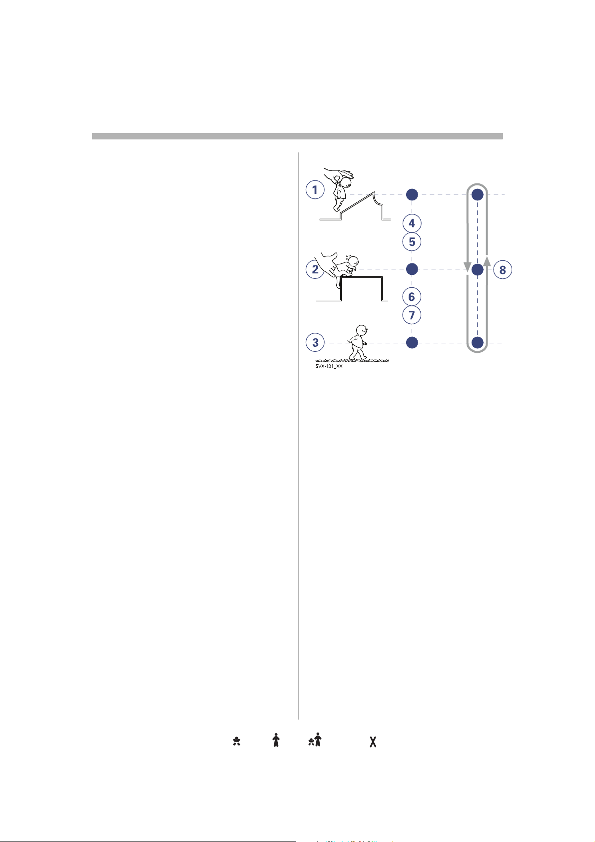
s
Modes of ventilationodes of ventilationdes of ventilationes of ventilations of ventilation of ventilationof ventilationf ventilation ventilationventilationentilationntilationtilationilationlationationtioniononn
2
Ventilatory managemententilatory managementntilatory managementtilatory managementilatory managementlatory managementatory managementtory managementory managementry managementy management managementmanagementanagementnagementagementgementementmententntt
The Servo-i Ventilator System is designed for lator System is designed for
safe and effective treatment. It can be set for be set for
continuous adaptation to the patient´s
prevailing condition or for manually manually
controlled operations. The servo systems for vo systems for
pressure, flow and timing operate in all g operate in all
modes of ventilation (set time in control
modes and patient-related timing in support
modes).).
Important:
• To show all available installed ventilation
modes, please refer to "Setting ventilation please refer to "Setting ventilation
mode" on page 164 in this manual.64 in this manual.
• In all pressure controlled modes, it is d modes, it is
important to set alarm limits to adequate
levels.
• For information about default values and bout default values and
parameter settings refer to page 249.249.
Applicationon
The Servo-i ventilator system also contains ystem also contains
tools to assist the user in application of lung
recruitment methodologies.dologies.
Scope - ventilatory needs cope - ventilatory needs ope - ventilatory needs pe - ventilatory needs e - ventilatory needs - ventilatory needs - ventilatory needs ventilatory needs ventilatory needs entilatory needs ntilatory needs tilatory needs ilatory needs latory needs atory needs tory needs ory needs ry needs y needs needs needs eeds eds ds s
The ventilator can be used for true::
1. controlled ventilation
2. supported ventilation, or
3. spontaneous breathing/CPAPbreathing/CPAP
4-7. It also allows for combined ventilatory It also allows for combined ventilatory
control or support. Spontaneous breathing upport. Spontaneous breathing
efforts are sensed during controlled controlled
ventilation, e.g. Volume Control. Mandatory Mandatory
ventilation can be used during supported/pported/
spontaneous breathing, e.g. the enhanced
SIMV functionality.
8. The Automode functionality continuously he Automode functionality continuously
adapts to the patient´s breathing capability. pts to the patient´s breathing capability.
When required, all ventilation is provided for quired, all ventilation is provided for
mandatorily. When the patient is able to When the patient is able to
initiate a breath, the ventilator supports and
monitors the patient´s breathing capability
and controls ventilation only if required.d controls ventilation only if required.
16
Servo… User´s manual
US edition
Infant Adult Universal Option
Order No: 66 00 261
Page 19
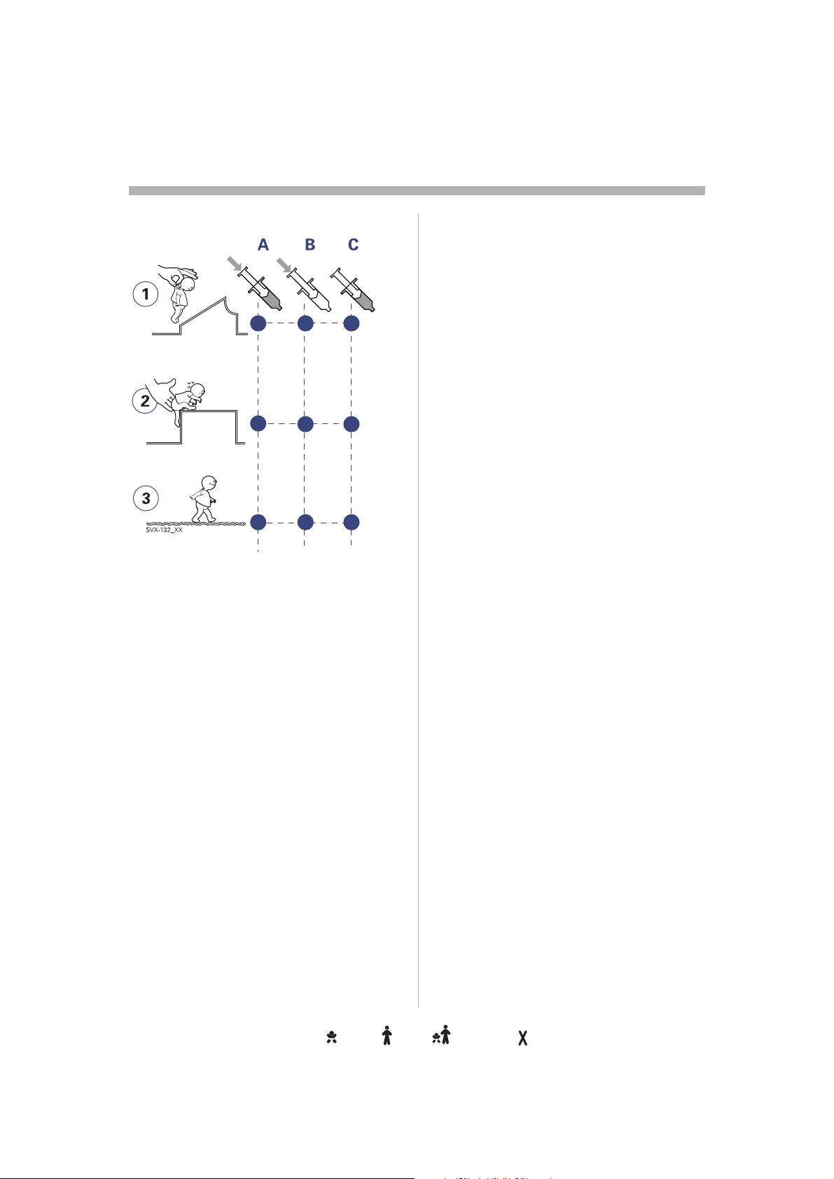
Modes of ventilationodes of ventilationdes of ventilationes of ventilations of ventilation of ventilationof ventilationf ventilation ventilationventilationentilationntilationtilationilationlationationtioniononn
2
Implementationmplementationplementationlementationementationmentationentationntationtationationtioniononn
Ventilation can be managed and
administered with a focus on:h a focus on:
A. pressure and volume
B. pressure
C. flow/volume.
Extra flow and extra breathsra flow and extra breaths
In flow/volume- oriented modes of d modes of
ventilation, additional on-demand flow can
be triggered during inspiration. Additional uring inspiration. Additional
breaths can always be triggered between the ways be triggered between the
ordinary breaths if the set trigger criteria are
met.
Timingming
In controlled ventilation modes, timing is
related to preset values. In supported
ventilation modes, timing is related to patient
triggering and Inspiratory cycle-off setting. ff setting.
Pressure and volume in focusd volume in focus
In the pressure- he pressure- and flow- oriented modes, a
constant inspiratory Tidal Volume is y Tidal Volume is
maintained. The inspiratory pressure level is ratory pressure level is
constant during each breath. (PRVC, Volume breath. (PRVC, Volume
Support.)
Pressure in focus
In the pressure-oriented modes, a constant
preset pressure level is maintained during vel is maintained during
inspiration. (Pressure Control, Pressure Control, Pressure
Support)
Flow/volume in focusw/volume in focus
In the flow/volume oriented modes a w/volume oriented modes a
constant inspiratory volume is maintained. y volume is maintained.
The inspiratory flow is constant during each flow is constant during each
breath (Volume Control).Volume Control).
Servo… User´s manual
US edition
Order No: 66 00 261
Infant Adult Universal Options
17
Page 20
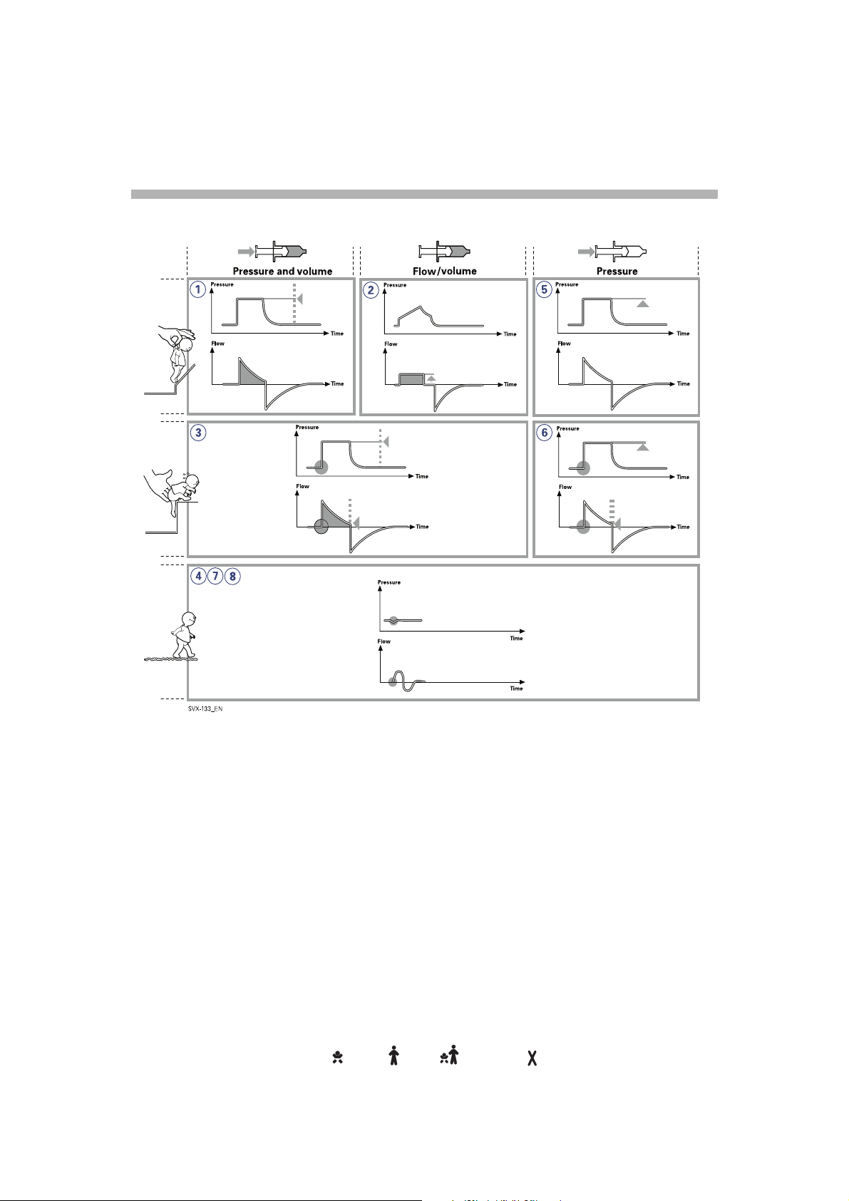
s
Modes of ventilationodes of ventilationdes of ventilationes of ventilations of ventilation of ventilationof ventilationf ventilation ventilationventilationentilationntilationtilationilationlationationtioniononn
2
Basic functionality - An overview asic functionality - An overview sic functionality - An overview ic functionality - An overview c functionality - An overview functionality - An overview functionality - An overview unctionality - An overview nctionality - An overview ctionality - An overview tionality - An overview ionality - An overview onality - An overview nality - An overview ality - An overview lity - An overview ity - An overview ty - An overview y - An overview - An overview - An overview An overview An overview n overview overview overview verview erview rview view iew ew w
18
Servo… User´s manual
US edition
Infant Adult Universal Option
Order No: 66 00 261
Page 21

1.(PRVC) Pressure Regulated ressure Regulated
Volume Control
Breaths are delivered mandatorily to assure mandatorily to assure
preset volumes, with a constant inspiratory constant inspiratory
pressure continuously adapting to the
patient´s condition. The flow pattern is flow pattern is
decelerating.
2. Volume Control trol
Breaths are delivered mandatorily with a vered mandatorily with a
constant flow to assure preset volumes. preset volumes.
3. Volume Support pport
A patient-adapted constant inspiratory
support is supplied when activated by when activated by
patient effort. The resulting volume is The resulting volume is
continuously monitored and the constant and the constant
inspiratory pressure automatically adjusts to
the required level. The patient determines quired level. The patient determines
frequency and duration of the breaths which cy and duration of the breaths which
show a decelerating flow pattern.g flow pattern.
4. Spontaneous breathing (CPAP)s breathing (CPAP)CPAP)
When sufficient inspiratory volumes are y volumes are
achieved, spontaneous breathing without breathing without
ventilator support is allowed for in Volume for in Volume
Support.
5. Pressure Control ontrol
Breaths are delivered mandatorily at a preset s are delivered mandatorily at a preset
pressure level, causing a decelerating flow flow
pattern.
6. Pressure Support Support
Inspiration is supported by a constant preset
pressure when activated by patient effort. hen activated by patient effort.
The patient determines frequency and mines frequency and
duration of the breaths, which show a , which show a
decelerating flow pattern. Inspiratory breath breath
duration can be influenced by adjusting the
Inspiratory cycle-off criteria.piratory cycle-off criteria.
7. Spontaneous breathing/CPAPs breathing/CPAPCPAP
True spontaneous breathing (CPAP) occurs g (CPAP) occurs
when the inspiratory pressure level is set to the inspiratory pressure level is set to
zero in Pressure Support.
8. Nasal CPAP
Spontaneous breathing on a set pressure breathing on a set pressure
level.
Modes of ventilationodes of ventilationdes of ventilationes of ventilations of ventilation of ventilationof ventilationf ventilation ventilationventilationentilationntilationtilationilationlationationtioniononn
2
Servo… User´s manual
US edition
Order No: 66 00 261
Infant Adult Universal Options
19
Page 22

s
Modes of ventilationodes of ventilationdes of ventilationes of ventilations of ventilation of ventilationof ventilationf ventilation ventilationventilationentilationntilationtilationilationlationationtioniononn
2
Combined modes - An ombined modes - An mbined modes - An bined modes - An ined modes - An ned modes - An ed modes - An d modes - An modes - An modes - An odes - An des - An es - An s - An - An - An An An n
overviewverviewerviewrviewviewieweww
Automodeutomode
The ventilator continuously adapts to the
patient's breathing capability and allows the breathing capability and allows the
patient to better interact with the ventilator. ventilator.
The ventilator automatically shifts between between
controlled ventilation, supported ventilation
and spontaneous ventilation. Each h
controlled ventilation mode has a
corresponding support mode.
Volume Control <----> Volume Support
PRVCRVC <----> Volume Support
Pressure Control <----> Pressure Support
When the patient is making a breathing
effort, the ventilator immediately switches to ort, the ventilator immediately switches to
a support mode of ventilation. If the patient is pport mode of ventilation. If the patient is
not making any breathing effort, the y breathing effort, the
ventilator will return to the controlled mode d mode
and deliver controlled breaths.
Synchronized intermittent chronized intermittent
Mandatory ventilation (SIMV)ilation (SIMV))
The ventilator provides mandatory breaths y breaths
which are synchronized with the patient´s
spontaneous efforts at a preset rate. The us efforts at a preset rate. The
mandatory breaths can be Volume Control, breaths can be Volume Control,
Pressure Control or PRVC breaths.
Bi-Vent
Bi-Vent is pressure controlled breathing, g,
giving the patient the opportunity of
unrestricted spontaneous breathing. Two breathing. Two
pressure levels are set together with the
individually set duration of each level. dividually set duration of each level.
Spontaneous efforts can be assisted by pontaneous efforts can be assisted by
pressure support.
20
Servo… User´s manual
US edition
Infant Adult Universal Option
Order No: 66 00 261
Page 23
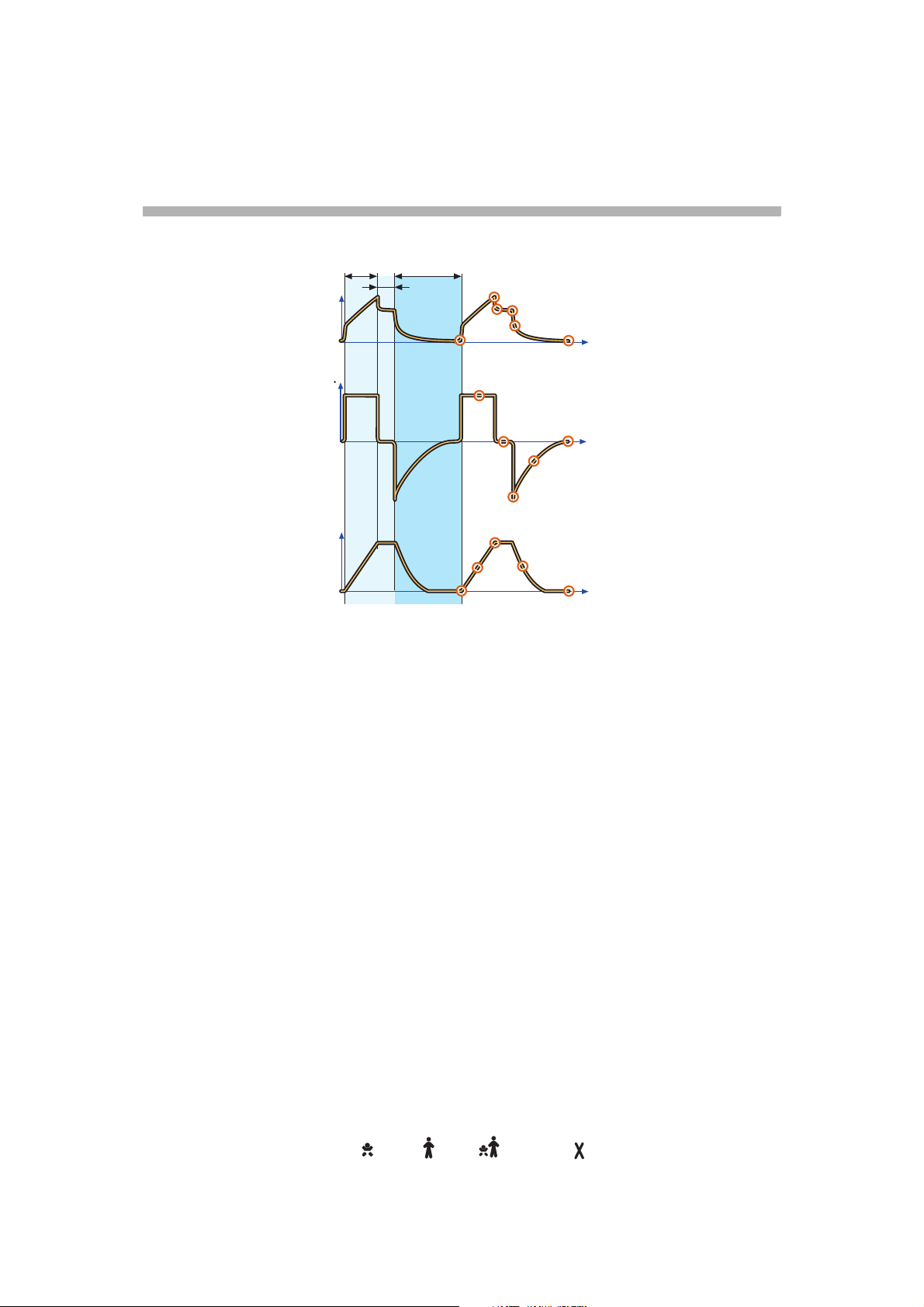
Important definitionsmportant definitionsportant definitionsortant definitionsrtant definitionstant definitionsant definitionsnt definitionst definitions definitionsdefinitionsefinitionsfinitionsinitionsnitionsitionstionsionsonsnss
2
x
V
V
ServoS-0046_XX
z
y
I:E
The graphic display of flow, pressure and ure and
volume is visualized in wave forms. Modes of
ventilation directly affect flow, pressure and ctly affect flow, pressure and
volume patterns.
Volume Contrololume Controllume Controlume Controlme Controle Control ControlControlontrolntroltrolrololl
Pressure-Time waveform. Points ure-Time waveform. Points orm. Points
and regions of interestegions of interest
X. Inspiration time
Y. Pause time
Z. Expiration timeExpiration time
1. Start of Inspiration
2. Peak inspiratory pressure
3. Early inspiratory pause pressure
4. End inspiratory pause pressured inspiratory pause pressure
5. Early expiratory pressure
6. End expiratory pressure
2
4
3
1
12
5
7
8
14
13
6
t
11
t
10
9
15
16
t
Flow-Time waveform. Points and w-Time waveform. Points and Points and
regions of interestf interest
X. Inspiration timeX. Inspiration time
Y. Pause time
Z: Expiration timeExpiration time
7. Peak inspiratory flowflow
8. Zero flow phase
9. Peak expiratory flowxpiratory flow
10. Slope decelerating expiratory limbng expiratory limb
11. End expiratory flowflow
Volume-Time waveform. Points me-Time waveform. Points Points
and regions of interestf interest
X. Inspiration time
Y. Pause timeuse time
Z. Expiration time
12. Start of inspiration
13. The slope represents current delivery of urrent delivery of
inspiratory tidal volume
14. End inspiration
15. The slope represents current patient urrent patient
delivery of expiratory tidal volume
16. End expiration
Servo… User´s manual
US edition
Order No: 66 00 261
Infant Adult Universal Options
21
Page 24
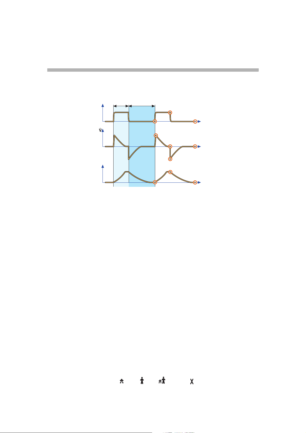
s
Important definitionsmportant definitionsportant definitionsortant definitionsrtant definitionstant definitionsant definitionsnt definitionst definitions definitionsdefinitionsefinitionsfinitionsinitionsnitionsitionstionsionsonsnss
2
P
V
ServoS-0047_XX
X
Z
I:E
Pressure Controlressure Controlessure Controlssure Controlsure Controlure Controlre Controle Control ControlControlontrolntroltrolrololl
Pressure-Time waveform. Points waveform. Points nts
and regions of interest
X. Inspiration time
Z. Expiration time
1. Start of Inspiration
2. Peak inspiratory pressure
3. End expiratory pressured expiratory pressure
2
1
4
5
6
9
8
3
t
7
t
10
t
Volume-Time waveform. Points me-Time waveform. Points Points
and regions of interestf interest
X. Inspiration timeme
Z.: Expiration time
8. Start of inspiration
9. End inspiration
10. End expiration
Flow-Time waveform. Points and form. Points and
regions of interestegions of interest
X. Inspiration time
Z. Expiration time
4. Peak inspiratory flowy flow
5. End inspiratory flow
6. Peak expiratory flow
7. End expiratory flowd expiratory flow
22
Infant Adult Universal Option
Servo… User´s manual
US edition
Order No: 66 00 261
Page 25
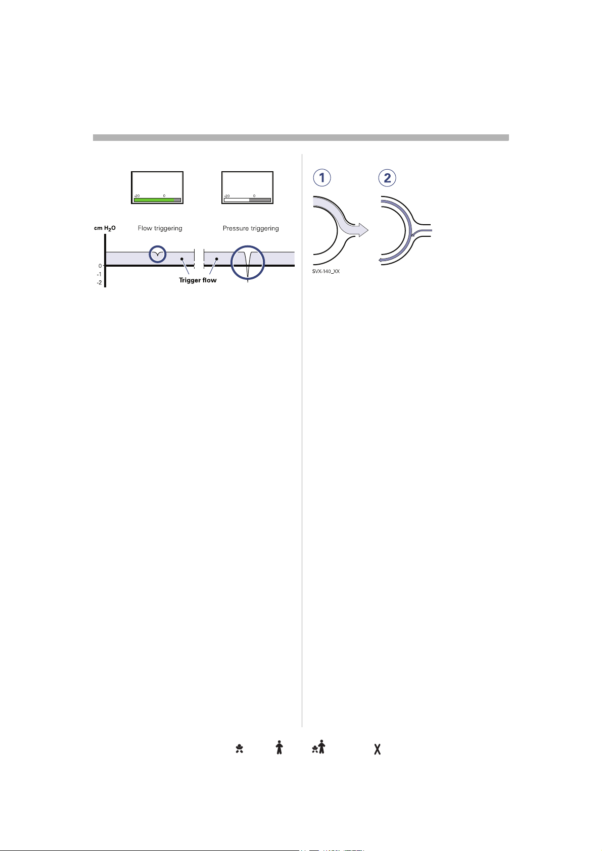
Trigger functionalityigger functionalitygger functionalityger functionalityer functionalityr functionality functionalityfunctionalityunctionalitynctionalityctionalitytionalityionalityonalitynalityalitylityitytyy
Trigg. Flow
5
Trigg. Pressure
-2
Trigger sensitivityTrigger sensitivityrigger sensitivityigger sensitivitygger sensitivityger sensitivityer sensitivityr sensitivity sensitivitysensitivityensitivitynsitivitysitivityitivitytivityivityvityitytyy
2
SVX-638_EN
This determines the level of patient effort to
trigger the ventilator to inspiration.gger the ventilator to inspiration.
Trigger sensitivity can be set in flow flow
triggering (Trigg. Flow) or pressure triggering
(Trigg. PressurePressure). Normally flow triggering is y flow triggering is
preferable as this enables the patient to
breath with less effort.
The sensitivity is set as high as possible vity is set as high as possible
without self-triggering. This ensures that ng. This ensures that
triggering is patient initiated and avoids autocycling by the ventilator.ycling by the ventilator.
Pressure triggering can be set in the range
-20 to 0 cmH20 to 0 cmH
level, white area on the bar).
O (in reference to set PEEP EEP
2
When the trigger sensitivity is set above 0 gger sensitivity is set above 0
(green and red area on the bar), flow flow
triggering is set, i.e. the amount of the bias
flow that the patient has to inhale to trigg a
new breath. The sensitivity can be set from The sensitivity can be set from
100% of the bias flow (left), to 0% of the bias 00% of the bias flow (left), to 0% of the bias
flow (right). For information about the ght). For information about the
different colors of the bar refer to page 167.lors of the bar refer to page 167.
Important: In
NIV it is not possible to set
trigger sensitivity.
The ventilator continuously delivers a gas he ventilator continuously delivers a gas
flow during expiration, which is measured in xpiration, which is measured in
the expiratory channel.y channel.
1. Inspiration.
Bias flow during expiration.during expiration.
2. Bias flow Infant 0.5 l/min.w Infant 0.5 l/min.
Bias flow: Adult 2 l/min.dult 2 l/min.
Servo… User´s manual
US edition
Order No: 66 00 261
Infant Adult Universal Options
233
Page 26
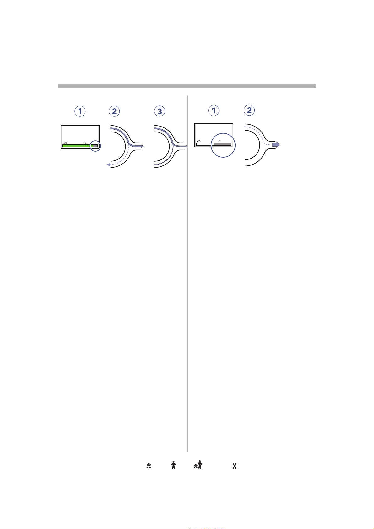
s
Trigger sensitivityrigger sensitivityigger sensitivitygger sensitivityger sensitivityer sensitivityr sensitivity sensitivitysensitivityensitivitynsitivitysitivityitivitytivityivityvityitytyy
2
Weak patient effort k patient effort
Trigg. Flow
5
SVX-141_EN
1. At a Trigger sensitivityer sensitivity level above zero
(0), the ventilator senses deviations in
the bias flow caused by inspiratory flow caused by inspiratory
efforts of the patient. The more to the he patient. The more to the
right on the scale, the more sensitive is
the trigger function.unction.
2. Weak inspiratory effort.
3. Very weak inspiratory effort.
For further information see page 167.urther information see page 167.
WARNING! NING! If the trigger sensitivity is set too vity is set too
high, a self triggering (auto-triggering)
condition may be reached. This condition dition may be reached. This condition
can also be reached if there is leakage in the kage in the
breathing system, e.g. if an uncuffed d
endotracheal tube is used. Triggering will
then be initiated by the system and not by the y the system and not by the
patient.This should always be avoided by ways be avoided by
decreasing the trigger sensitivity.
Stronger patient effortger patient effort
Trigg. Pressure
-2
SVX-142_EN
1. At a Trigger sensitivity level below zero zero
(0), the ventilator senses negative
pressures created by the patient. created by the patient.
Required preset negative pressure to gative pressure to
initiate a breath is shown numerically. cally.
The more to the left on the scale, the
more effort is required to trigger.d to trigger.
2. Stronger patient effort.
For further information see page 167.mation see page 167.
WARNING! The trigger sensitivity bar has vity bar has
different colors based on the setting. A green A green
bar indicates a normal setting for the flow w
triggering. The risk of self-triggering
increases when the bar is red. A white bar d. A white bar
indicates that pressure triggering is required.quired.
24
Servo… User´s manual
US edition
Infant Adult Universal Option
Order No: 66 00 261
Page 27
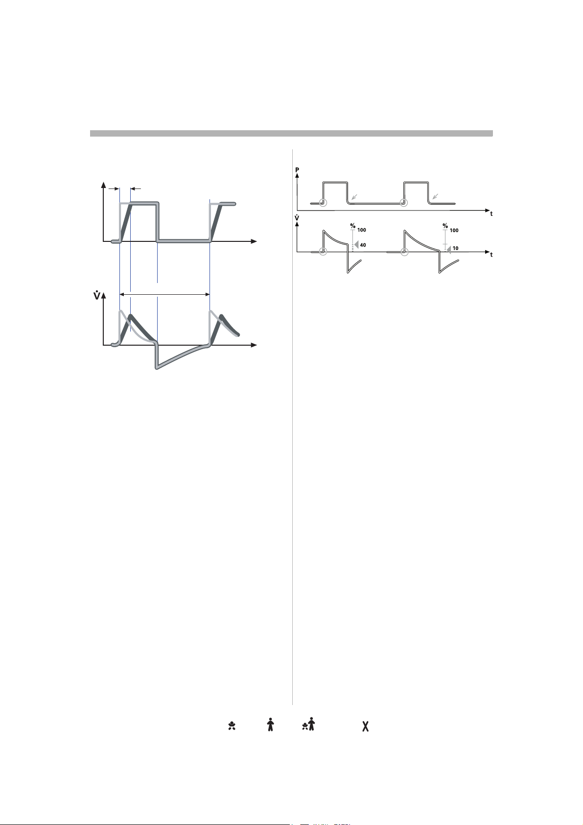
Settingsettingsttingstingsingsngsgss
2
Inspiratory rise timenspiratory rise timespiratory rise timepiratory rise timeiratory rise timeratory rise timeatory rise timetory rise timeory rise timery rise timey rise time rise timerise timeise timese timee time timetimeimemee
Insp rise time
P
0
100 %
0
SVX-644_EN
Time to peak inspiratory flow or pressure at nspiratory flow or pressure at
the start of each breath as a percentage of ge of
the respiratory cycle time or in seconds.
Increased rise time will affect the rate of flow/will affect the rate of flow/
pressure increase and can be evaluated by valuated by
the shape of the flow and pressure
waveforms.ms.
Inspiratory rise time (%) is applicable in ble in
Pressure Control, Volume Control, PRVC,
SIMV-Volume Control, SIMV-Pressure
Control, SIMV-PRVC. Setting can be in the RVC. Setting can be in the
range 0-20% of the respiratory cycle time.0-20% of the respiratory cycle time.me.
Inspiratory rise time set in seconds is
applicable in Pressure Support, Volume ure Support, Volume
Support and Bi-Vent. For adults the range is For adults the range is
0-0.4 seconds and for infants the range is 0-for infants the range is 0-
0.2 seconds.
Note: When the ventilator is configured for
setting of Inspiration time, the unit for piration time, the unit for
Inspiratory rise time then automatically
switches to seconds for all ventilation ds for all ventilation
modes.
t
t
Inspiratory cycle-offnspiratory cycle-offspiratory cycle-offpiratory cycle-offiratory cycle-offratory cycle-offatory cycle-offtory cycle-offory cycle-offry cycle-offy cycle-off cycle-offcycle-offycle-offcle-offle-offe-off-offofffff
SVX-205_XX
Inspiratory Cycle-off is the point at which
inspiration changes to expiration in ges to expiration in
spontaneous and supported modes of
ventilation. A decrease of the inspiratory flow A decrease of the inspiratory flow
to a preset level causes the ventilator to vel causes the ventilator to
switch to expiration. This preset level is
measured as a percentage of the maximum
flow during inspiration. The range of w during inspiration. The range of
Inspiratory cycle-off is 1 - 70%. - 70%.
Note: In NIV the range is 10-70%.
Normally in supported modes the Inspiratory he Inspiratory
rise time should be increased from the from the
default setting and so give more comfort to
the patient.
Servo… User´s manual
US edition
Order No: 66 00 261
Infant Adult Universal Options
25
Page 28
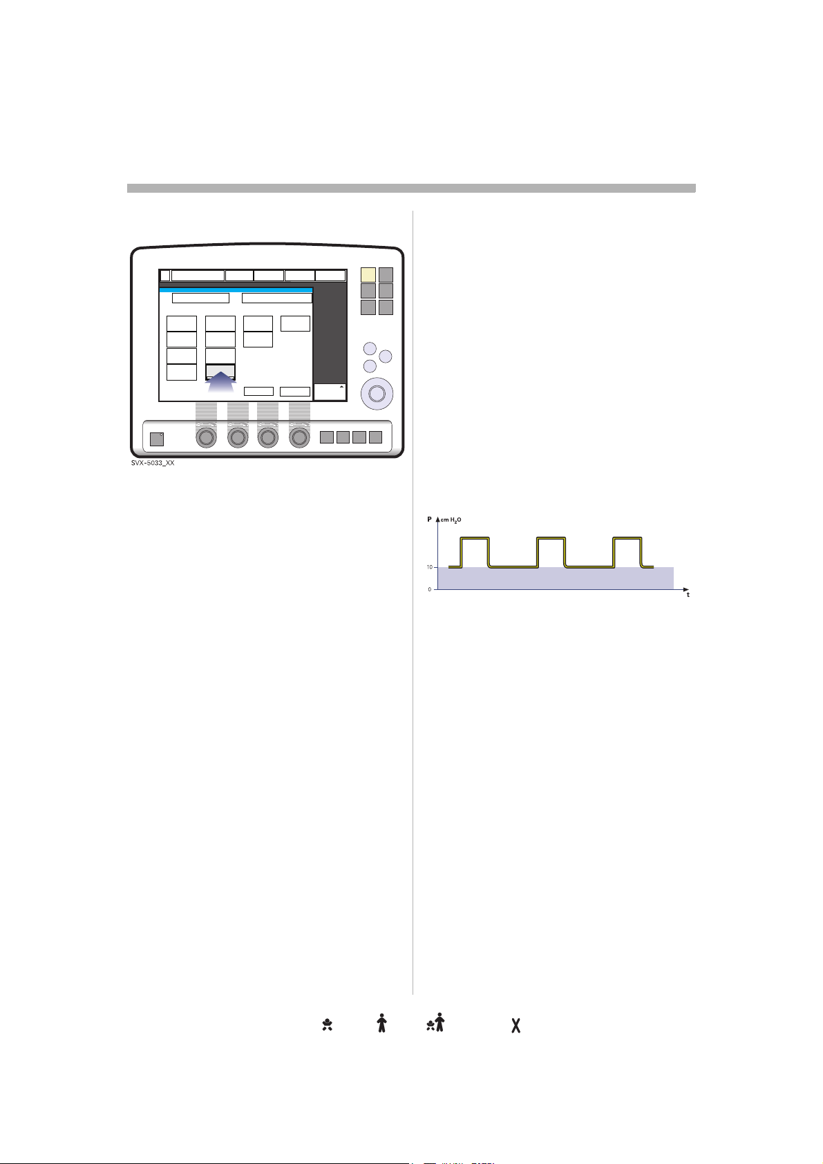
s
Settingsettingsttingstingsingsngsgss
2
Breath cycle timereath cycle timeeath cycle timeath cycle timeth cycle timeh cycle time cycle timecycle timeycle timecle timele timee time timetimeimemee
This is the length of the breath i.e. the total
cycle time of the mandatory breath in SIMV ycle time of the mandatory breath in SIMV MV
(inspiration, pause plus expiration). This is his is
set in seconds within the range:
Infants: 0,5 -15 seconds in half second steps.15 seconds in half second steps.
Adults: 1-15 seconds in one second steps.
Note: The soft key Breath cycle time is not
shown when an SIMV mode is selected and wn when an SIMV mode is selected and cted and
inspiration time is configured. Refer to
heading I:E ratio / Inspiration times.
Trigger timeoutrigger timeoutigger timeoutgger timeoutger timeouter timeoutr timeout timeouttimeoutimeoutmeouteoutoututt
Trigger Timeout is the maximum allowed
apnea time in Automode before controlled pnea time in Automode before controlled
ventilation is activated. It is applicable in:s activated. It is applicable in:
Automode:
Volume Control
PRVC
Pressure Controlssure Control
The settings are within the ranges:are within the ranges:
• Infant: 3-7 seconds
• Adult: 7-12 seconds
Initially the ventilator adapts with a dynamic he ventilator adapts with a dynamic
Trigger Timeout limit. This means that for the
spontaneously triggering patient the timeout
increases successively during the first ten creases successively during the first ten
breaths.
<--->Volume Support
<--->Volume Support
<--->Pressure Support
PEEPEEPEPP
PEEP
SVX-646_EN
Positive End Expiratory Pressure (PEEP) can ) can
be set in the range of 0 - 50 cmHH
Positive End Expiratory Pressure is piratory Pressure is
maintained in the alveoli and may prevent the
collapse of the airways.
Note: In NIV the range is 2-20 V the range is 2-20 cmH
O. A
2
2
O.
26
Servo… User´s manual
US edition
Infant Adult Universal Option
Order No: 66 00 261
Page 29

Settingsettingsttingstingsingsngsgss
2
I:E ratio / Inspiration time:E ratio / Inspiration timeE ratio / Inspiration time ratio / Inspiration timeratio / Inspiration timeatio / Inspiration timetio / Inspiration timeio / Inspiration timeo / Inspiration time / Inspiration time/ Inspiration time Inspiration timeInspiration timenspiration timespiration timepiration timeiration timeration timeation timetion timeion timeon timen time timetimeimemee
The setting of breathing parameters in parameters in
Servo-i can be configured in two different ured in two different
ways, based on:
• I:E ratio (independent of changes of e.g. pendent of changes of e.g.
the breathing frequency) or,y) or,
• Inspiration time in seconds (independent
of changes of e.g. the breathing hanges of e.g. the breathing
frequency), to better meet the meet the
requirements for infant care.
When the ventilator is configured for setting gured for setting
of Inspiration time, the unit for Pause time
and Insp. rise time then automatically cally
switches to seconds. The resulting I:E ratio :E ratio
for each setting is shown in the upper right
information area of the ventilation mode mation area of the ventilation mode
window.
As the inspiration time is explicitly set, a xplicitly set, a
change of for example the Respiratory Rate Respiratory Rate
will affect the I:E ratio. As a safety precaution, As a safety precaution,
it will therefore be indicated when the be indicated when the
resulting I:E ratio passes 1:1 in either passes 1:1 in either
direction.
Note: The soft key Breath cycle time is not y Breath cycle time is not
shown when an SIMV mode is selected, MV mode is selected,
since there is no need to set Breath cycle ycle
time when Inspiration time is directly set.
Note: The configuration is done by a service y a service
technician with a service card.
Volume settingolume settinglume settingume settingme settinge setting settingsettingettingttingtingingngg
Depending on the ventilator configuration the on the ventilator configuration the
inspiratory volume can be set as:be set as:
– Minute Volume or,
– Tidal Volumedal Volume
Note: The configuration is done by a service s done by a service
technician with a service card.
Controlled / supported ontrolled / supported ntrolled / supported trolled / supported rolled / supported olled / supported lled / supported led / supported ed / supported d / supported / supported / supported supported supported upported pported ported orted rted ted ed d
pressure levelressure levelessure levelssure levelsure levelure levelre levele level levellevelevelvelell
PC (Pressure Control level) above PEEP is C (Pressure Control level) above PEEP is
the set inspiratory pressure level for each he set inspiratory pressure level for each
mandatory breath in Pressure Control and breath in Pressure Control and
SIMV (PC) + PS, and also for Apnea back-up MV (PC) + PS, and also for Apnea back-up for Apnea back-up
in Pressure Support.Support.
PS (Pressure Support level) above PEEP is
the set inspiratory pressure support level for he set inspiratory pressure support level for
triggered breaths in Pressure Support, SIMV breaths in Pressure Support, SIMV V
modes and Bi-Vent.
O2 concentrationconcentrationoncentrationncentrationcentrationentrationntrationtrationrationationtioniononn
The setting range for the gas mixer is 21% Ofor the gas mixer is 21% OO2
to 100% O
automatically set at approximately 6% Outomatically set at approximately 6% OO
above or below the set concentration value.
There is also an absolute minimum alarm minimum alarm
limit of 18% O
operating settings.
. The alarm limits are
2
which is independent of ch is independent of
2
2
Respiratory rate / SIMV espiratory rate / SIMV spiratory rate / SIMV piratory rate / SIMV iratory rate / SIMV ratory rate / SIMV atory rate / SIMV tory rate / SIMV ory rate / SIMV ry rate / SIMV y rate / SIMV rate / SIMV rate / SIMV ate / SIMV te / SIMV e / SIMV / SIMV / SIMV SIMV SIMV IMV MV V
frequencyrequencyequencyquencyuencyencyncycyy
Respiratory rate is the number of controlled umber of controlled
mandatory breaths per minute in controlled inute in controlled
modes excluding SIMV. The respiratory rate V. The respiratory rate
is also used for calculation of tidal volume if n of tidal volume if
the ventilator is configured for Minute volume Minute volume
setting. SIMV rate is the number of controlled he number of controlled
mandatory breaths in SIMV modes.SIMV modes.
Servo… User´s manual
US edition
Order No: 66 00 261
Infant Adult Universal Options
27
Page 30
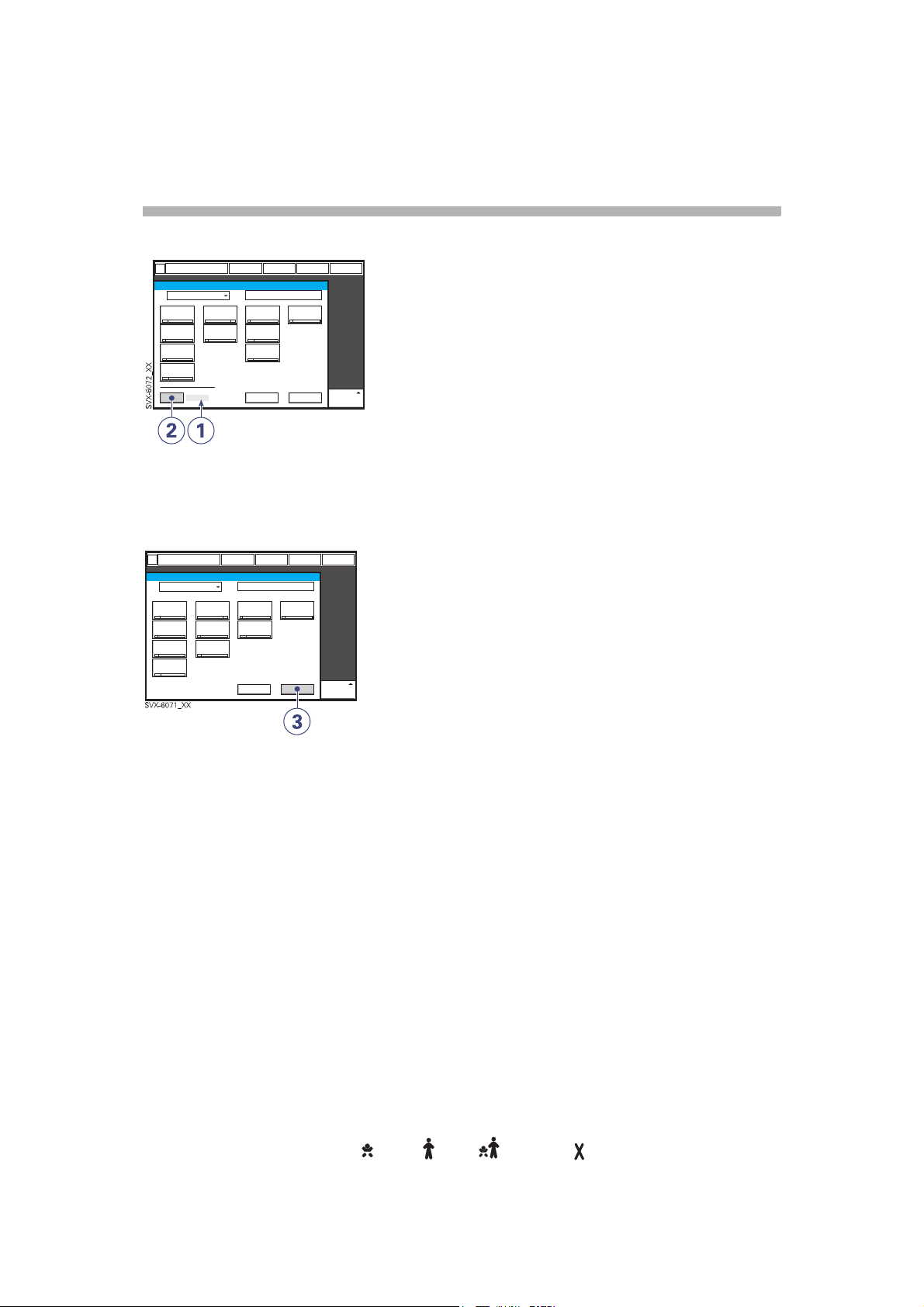
s
Settingsettingsttingstingsingsngsgss
2
Previous ventilation moderevious ventilation modeevious ventilation modevious ventilation modeious ventilation modeous ventilation modeus ventilation modes ventilation mode ventilation modeventilation modeentilation modentilation modetilation modeilation modelation modeation modetion modeion modeon moden mode modemodeodedee
1. Time when previous mode was when previous mode was
inactivated.
2. Press the pad Show previous mode to
recall the previous accepted ventilation
mode.
3. Activate the previous used ventilation ntilation
mode settings by pressing the Accept
pad.
Note:
• The previous ventilation mode function is
not available after a Pre-use check, ble after a Pre-use check,
changing of patient category, admitting a patient category, admitting a
new patient, use of the same ventilation f the same ventilation
mode for more than 24 hours or after startup (cold start) of the system.p (cold start) of the system.
• In backup ventilation, the ventilator shows n backup ventilation, the ventilator shows
the settings for the supported mode when gs for the supported mode when
previous mode is activated.ctivated.
• A recall of previous settings is only y
possible after a change of ventilation
mode.
28
Infant Adult Universal Option
Servo… User´s manual
US edition
Order No: 66 00 261
Page 31

Special functionspecial functionsecial functionscial functionsial functionsal functionsl functions functionsfunctionsunctionsnctionsctionstionsionsonsnss
2
Fixed keysixed keysxed keysed keysd keys keyskeyseysyss
1. Start breath
breathss
2. O
2
3. Expiratory hold
4. Inspiratory hold
can all be chosen by manually pressing the
respective fixed key.ve fixed key.
Start breathbreath
The ventilator will initiate a new breath cycle breath cycle
according to the current ventilator settings.
Servo… User´s manual
US edition
Order No: 66 00 261
Infant Adult Universal Options
29
Page 32

s
Special functionspecial functionsecial functionscial functionsial functionsal functionsl functions functionsfunctionsunctionsnctionsctionstionsionsonsnss
2
O2 breaths
This function allows 100% oxygen to be % oxygen to be
given for 1 minute. After this time the oxygen After this time the oxygen
concentration will return to the pre-set value. will return to the pre-set value.
The oxygen breaths can be interrupted by gen breaths can be interrupted by
repressing the O
the 1 minute interval.
breaths fixed key during key during
2
Expiratory holdxpiratory hold
Expiratory and inspiratory valves are closed xpiratory and inspiratory valves are closed
after the expiration phase is completed, for , for
as long as the fixed key is depressed, up to a up to a
maximum of 30 seconds. Expiratory hold Expiratory hold
provides an exact measurement of the end measurement of the end
expiratory pause pressure. It can be used for be used for
static compliance measuring and to
determine the total PEEP. The dynamic he total PEEP. The dynamic
pressure is shown on the PEEP numerical
value.
30
Servo… User´s manual
US edition
Infant Adult Universal Option
Order No: 66 00 261
Page 33

Special functionspecial functionsecial functionscial functionsial functionsal functionsl functions functionsfunctionsunctionsnctionsctionstionsionsonsnss
2
Inspiratory holdnspiratory holdd
Inspiratory hold is activated by manually by manually
pressing the fixed key. The maximum time is d key. The maximum time is
30 seconds. The inspiratory and expiratory conds. The inspiratory and expiratory
valves close after inspiration. This function fter inspiration. This function
can provide an exact measurement of the measurement of the
end inspiratory lung pressure. It can be used can be used
during x-ray or to determine Plateau Plateau
pressure, or static compliance calculation.
Back-up ventilationack-up ventilationck-up ventilationk-up ventilation-up ventilationup ventilationp ventilation ventilationventilationentilationntilationtilationilationlationationtioniononn
Pressure support/
CPAP
Apnea
Volume support
SVX-647_EN
Back-up ventilation is available in all support ble in all support
modes (not applicable in Automode and NIV NIV
Pressure Support mode).
The Back-up function switches Volume Volume
Support to Volume Control, Pressure
Support and CPAP to Pressure Control. d CPAP to Pressure Control.
During Back-up ventilation default settings Back-up ventilation default settings
are used for I:E ratio, Respiratory Rate, and I:E ratio, Respiratory Rate, and
Inspiratory rise time. Apnea alarm can be set Apnea alarm can be set
in infant mode (5-45 seconds) and in adult 5-45 seconds) and in adult
mode (15-45 seconds). The Back-up The Back-up
pressure level is adjustable, minimum ble, minimum
settable value is 5 cmH
Note: Back-up not applicable in NIV Nasal k-up not applicable in NIV Nasal
CPAP.
O.
2
Pressure control
Volume control
Servo… User´s manual
US edition
Order No: 66 00 261
Infant Adult Universal Options
31
Page 34

s
Controlled ventilation - PRVControlled ventilation - PRVCntrolled ventilation - PRVCtrolled ventilation - PRVCrolled ventilation - PRVColled ventilation - PRVClled ventilation - PRVCled ventilation - PRVCed ventilation - PRVCd ventilation - PRVC ventilation - PRVCventilation - PRVCentilation - PRVCntilation - PRVCtilation - PRVCilation - PRVClation - PRVCation - PRVCtion - PRVCion - PRVCon - PRVCn - PRVC - PRVC- PRVC PRVCPRVCRVCVCC
2
Functional description PRVCunctional description PRVCnctional description PRVCctional description PRVCtional description PRVCional description PRVConal description PRVCnal description PRVCal description PRVCl description PRVC description PRVCdescription PRVCescription PRVCscription PRVCcription PRVCription PRVCiption PRVCption PRVCtion PRVCion PRVCon PRVCn PRVC PRVCPRVCRVCVCC
The Pressure Regulated Volume Control ated Volume Control
(PRVC) mode is a controlled breathing mode. ) mode is a controlled breathing mode.
Servo-i Ventilator can be configured to set vo-i Ventilator can be configured to set
Tidal Volume or Minute Volume. The
following parameters are set:wing parameters are set:
1. Tidal Volume (ml) or Minute Volume (l/olume (ml) or Minute Volume (l/
min)
2. Respiratory Rate (b/min)spiratory Rate (b/min)
3. PEEP (cmH
4. Oxygen concentration (%)en concentration (%)
5. I:E ratio / Insp. timeme
6. Inspiratory rise time (%/s))
7. Trigg. Flow / Trigg. Pressure
O)
2
The ventilator delivers a pre-set Tidal ventilator delivers a pre-set Tidal
Volume. The pressure is automatically he pressure is automatically
regulated to deliver the pre-set volume but but
limited to 5 cmH
pressure limit.
The flow during inspiration is decelerating. ation is decelerating.
The patient can trigger extra breaths.
O below the set upper set upper
2
32
Servo… User´s manual
US edition
Infant Adult Universal Option
Order No: 66 00 261
Page 35

PRVC in detailPRVC in detailRVC in detailVC in detailC in detail in detailin detailn detail detaildetailetailtailailill
Controlled ventilation - PRVControlled ventilation - PRVCntrolled ventilation - PRVCtrolled ventilation - PRVCrolled ventilation - PRVColled ventilation - PRVClled ventilation - PRVCled ventilation - PRVCed ventilation - PRVCd ventilation - PRVC ventilation - PRVCventilation - PRVCentilation - PRVCntilation - PRVCtilation - PRVCilation - PRVClation - PRVCation - PRVCtion - PRVCion - PRVCon - PRVCn - PRVC - PRVC- PRVC PRVCPRVCRVCVCC
2
1
SVX-9006_XX
1. PRVC assures a set target minute nute
ventilation to the patient. The target
volume is based upon settings for Tidal d upon settings for Tidal
Volume, frequency and inspiration time.quency and inspiration time.
2. The inspiratory pressure level is constant
during each breath, but automatically g each breath, but automatically
adapts in small increments breath-by-s in small increments breath-bybreath to match the patient´s lung
mechanical properties for target volume for target volume
delivery.
3. Inspiration starts according to a preset piration starts according to a preset
frequency or when the patient triggers.when the patient triggers.
Expiration starts::
a. After the termination of preset
inspiration time
b. If the upper pressure limit is
exceeded.
2
3
Servo… User´s manual
US edition
Order No: 66 00 261
Infant Adult Universal Options
33
Page 36

s
Controlled ventilation - PRVControlled ventilation - PRVCntrolled ventilation - PRVCtrolled ventilation - PRVCrolled ventilation - PRVColled ventilation - PRVClled ventilation - PRVCled ventilation - PRVCed ventilation - PRVCd ventilation - PRVC ventilation - PRVCventilation - PRVCentilation - PRVCntilation - PRVCtilation - PRVCilation - PRVClation - PRVCation - PRVCtion - PRVCion - PRVCon - PRVCn - PRVC - PRVC- PRVC PRVCPRVCRVCVCC
2
SVX-697_EN
The first breath of a start sequence is a
volume-controlled test breath with Pause -controlled test breath with Pause
time set to 10%. The measured pause 10%. The measured pause
pressure of this breath is then used as the f this breath is then used as the
pressure level for the following breath. An g breath. An
alarm is activated if the pressure level pressure level
required to achieve the set target volume
cannot be delivered due to a lower setting of nnot be delivered due to a lower setting of
the upper pressure limit (- 5 cmHpper pressure limit (- 5 cmH
2
O).
34
Servo… User´s manual
US edition
Infant Adult Universal Option
Order No: 66 00 261
Page 37

Controlled ventilation - Volume Controlontrolled ventilation - Volume Controlntrolled ventilation - Volume Controltrolled ventilation - Volume Controlrolled ventilation - Volume Contrololled ventilation - Volume Controllled ventilation - Volume Controlled ventilation - Volume Controled ventilation - Volume Controld ventilation - Volume Control ventilation - Volume Controlventilation - Volume Controlentilation - Volume Controlntilation - Volume Controltilation - Volume Controlilation - Volume Controllation - Volume Controlation - Volume Controltion - Volume Controlion - Volume Controlon - Volume Controln - Volume Control - Volume Control- Volume Control Volume ControlVolume Contrololume Controllume Controlume Controlme Controle Control ControlControlontrolntroltrolrololl
Functional description unctional description nctional description ctional description tional description ional description onal description nal description al description l description description description escription scription cription ription iption ption tion ion on n
Volume Contrololume Controllume Controlume Controlme Controle Control ControlControlontrolntroltrolrololl
2
Volume Controlled ventilation ensures that
the patient receives a certain pre-set Minute/patient receives a certain pre-set Minute/
Tidal Volume.Volume.
Servo-i Ventilator can be configured to set d to set
Tidal Volume or Minute Volume. The
following parameters are set:
1. Tidal Volume (ml) or the Minute Volume Volume (ml) or the Minute Volume
(l/min)
2. Respiratory Rate (b/min)
3. PEEP (cmH
4. Oxygen concentration (%)en concentration (%)
5. I:E ratio / Insp. timeme
6. Pause time (%/s)
7. Inspiratory rise time (%/s)piratory rise time (%/s)
8. Trigg. Flow / Trigg. Pressure
O)
2
The airway pressure is dependent on the pressure is dependent on the
tidal volume, inspiration time and the
resistance and compliance of the respiratory
system. The set tidal volume will always be The set tidal volume will always be
delivered. An increase in the resistance and red. An increase in the resistance and
decrease in compliance will lead to an
increased airway pressure. To protect the y pressure. To protect the
patient's lungs from excessive pressure, it is m excessive pressure, it is
very important to set the upper pressure limit
to a suitable value. ble value.
It is possible for the patient to trigger extra
breaths if they can overcome the pre-set y can overcome the pre-set
trigger sensitivity. It is also possible for the for the
patient, by their own inspiratory efforts, to
receive a higher inspiratory flow and Tidal gher inspiratory flow and Tidal
Volume during an inspiration than pre-set.
The flow during inspiration is constant. The constant. The
patient can trigger extra breaths.
Servo… User´s manual
US edition
Order No: 66 00 261
Infant Adult Universal Options
35
Page 38

s
Controlled ventilation - Volume Controlontrolled ventilation - Volume Controlntrolled ventilation - Volume Controltrolled ventilation - Volume Controlrolled ventilation - Volume Contrololled ventilation - Volume Controllled ventilation - Volume Controlled ventilation - Volume Controled ventilation - Volume Controld ventilation - Volume Control ventilation - Volume Controlventilation - Volume Controlentilation - Volume Controlntilation - Volume Controltilation - Volume Controlilation - Volume Controllation - Volume Controlation - Volume Controltion - Volume Controlion - Volume Controlon - Volume Controln - Volume Control - Volume Control- Volume Control Volume ControlVolume Contrololume Controllume Controlume Controlme Controle Control ControlControlontrolntroltrolrololl
2
Volume Controlled ventilation has, by s, by
tradition, delivered each breath with a
constant flow and constant inspiratory and piratory and
expiratory times, according to the settings.
The Servo-i gives the possibility to the
patient to modify both flow rate and timing. nt to modify both flow rate and timing.
So, if a pressure drop of 3 cmH
during inspiration, the ventilator cycles to ycles to
O is detected
2
Pressure Support with a resulting increase in g increase in
inspiratory flow. When the flow decreases to hen the flow decreases to
the calculated target level this flow will be
maintained until the set Tidal Volume is
delivered.
SVX-652_EN
The waveform illustrations above show some waveform illustrations above show some
practical consequences of this enhanced quences of this enhanced
functionality.
• the top waveform shows the trace for a waveform shows the trace for a
normal Volume Controlled breathControlled breath
• the second waveform shows a situation m shows a situation
when inspiration is prematurely interrupted
as the set tidal volume has been deliveredbeen delivered
• the third waveform shows a situation
where the patient maintains a flow rate patient maintains a flow rate
higher than the calculated target value. d target value.
The set Tidal Volume has been delivered been delivered
when calculated target flow is reached and
the inspiration is prematurely interruptedpiration is prematurely interrupted
• the bottom waveform, shows a situation waveform, shows a situation
where the increased flow rate is
maintained into the expiratory period. The piratory period. The
patient will receive a higher tidal volume gher tidal volume
than set due to a higher flow/volume
demand than calculated.calculated.
366
Servo… User´s manual
US edition
Infant Adult Universal Option
Order No: 66 00 261
Page 39

Controlled ventilation - Volume Controlontrolled ventilation - Volume Controlntrolled ventilation - Volume Controltrolled ventilation - Volume Controlrolled ventilation - Volume Contrololled ventilation - Volume Controllled ventilation - Volume Controlled ventilation - Volume Controled ventilation - Volume Controld ventilation - Volume Control ventilation - Volume Controlventilation - Volume Controlentilation - Volume Controlntilation - Volume Controltilation - Volume Controlilation - Volume Controllation - Volume Controlation - Volume Controltion - Volume Controlion - Volume Controlon - Volume Controln - Volume Control - Volume Control- Volume Control Volume ControlVolume Contrololume Controllume Controlume Controlme Controle Control ControlControlontrolntroltrolrololl
Volume Control in detailolume Control in detaillume Control in detailume Control in detailme Control in detaile Control in detail Control in detailControl in detailontrol in detailntrol in detailtrol in detailrol in detailol in detaill in detail in detailin detailn detail detaildetailetailtailailill
2
SVX-9002_XX
1. Volume Control assures a preset tidal ssures a preset tidal
volume with constant flow during a g a
preset inspiratory time at a preset
frequency.
2. The inspiratory flow is constant and d
depends on User Interface setting.
3. Inspiration starts according to the preset
frequency or when the patient triggers.quency or when the patient triggers.
4. If the patient makes an inspiratory effort
during the inspiratory period, the uring the inspiratory period, the
ventilator will switch to Pressure Support ch to Pressure Support
to satisfy the patient´s flow demand. w demand.
Expiration starts:
a. When the preset tidal volume is ume is
delivered and after the preset pause
time.
b. When the flow returns to the set value
after the preset tidal volume is me is
delivered and after the preset pause
time (on-demand support). The The
patient is however always guaranteed d
an expiration time corresponding to at
least 20% of the total breath.% of the total breath.
c. If the upper pressure limit is
exceeded.xceeded.
1 2
3
4
Servo… User´s manual
US edition
Order No: 66 00 261
Infant Adult Universal Options
37
Page 40

s
Controlled ventilation - Pressure Controlontrolled ventilation - Pressure Controlntrolled ventilation - Pressure Controltrolled ventilation - Pressure Controlrolled ventilation - Pressure Contrololled ventilation - Pressure Controllled ventilation - Pressure Controlled ventilation - Pressure Controled ventilation - Pressure Controld ventilation - Pressure Control ventilation - Pressure Controlventilation - Pressure Controlentilation - Pressure Controlntilation - Pressure Controltilation - Pressure Controlilation - Pressure Controllation - Pressure Controlation - Pressure Controltion - Pressure Controlion - Pressure Controlon - Pressure Controln - Pressure Control - Pressure Control- Pressure Control Pressure ControlPressure Controlressure Controlessure Controlssure Controlsure Controlure Controlre Controle Control ControlControlontrolntroltrolrololl
2
Functional description unctional description nctional description ctional description tional description ional description onal description nal description al description l description description description escription scription cription ription iption ption tion ion on n
Pressure Controlressure Controlessure Controlssure Controlsure Controlure Controlre Controle Control ControlControlontrolntroltrolrololl
The Pressure Controlled mode is a controlled ntrolled mode is a controlled
breathing mode.
The following parameters are set:wing parameters are set:
1. PC (Pressure Control level) above PEEP ontrol level) above PEEP
(cmH
O)
2
2. Respiratory Rate (b/min)min)
3. PEEP (cmH
4. Oxygen concentration (%)gen concentration (%)
5. I:E ratio / Insp. timep. time
6. Inspiratory rise time (%/s))
7. Trigg. Flow / Trigg. Pressure
O)
2
The delivered volume is dependent upon the delivered volume is dependent upon the
pressure above PEEP, lung compliance and EEP, lung compliance and
resistance in the patient tube system and he patient tube system and
airways. This means that the Tidal Volume This means that the Tidal Volume
can vary. Pressure Controlled mode is y. Pressure Controlled mode is
preferred when there is leakage in the when there is leakage in the
breathing system e.g. due to uncuffed ue to uncuffed
endotracheal tube or in situations when the
maximum airway pressure must be y pressure must be
controlled. The flow during inspiration is flow during inspiration is
decelerating. The patient can trigger extra he patient can trigger extra
breaths. If the patient tries to exhale during uring
the inspiration, the expiratory valve will allow
exhalation as long as the pressure is more more
than 3 cmH
As the delivered tidal volume can vary it is y it is
very important to set alarm limits for Minute
Volume to adequate levels.dequate levels.
O above the set pressure level. pressure level.
2
38
Servo… User´s manual
US edition
Infant Adult Universal Option
Order No: 66 00 261
Page 41

Controlled ventilation - Pressure Controlontrolled ventilation - Pressure Controlntrolled ventilation - Pressure Controltrolled ventilation - Pressure Controlrolled ventilation - Pressure Contrololled ventilation - Pressure Controllled ventilation - Pressure Controlled ventilation - Pressure Controled ventilation - Pressure Controld ventilation - Pressure Control ventilation - Pressure Controlventilation - Pressure Controlentilation - Pressure Controlntilation - Pressure Controltilation - Pressure Controlilation - Pressure Controllation - Pressure Controlation - Pressure Controltion - Pressure Controlion - Pressure Controlon - Pressure Controln - Pressure Control - Pressure Control- Pressure Control Pressure ControlPressure Controlressure Controlessure Controlssure Controlsure Controlure Controlre Controle Control ControlControlontrolntroltrolrololl
Pressure Control in detail ressure Control in detail essure Control in detail ssure Control in detail sure Control in detail ure Control in detail re Control in detail e Control in detail Control in detail Control in detail ontrol in detail ntrol in detail trol in detail rol in detail ol in detail l in detail in detail in detail n detail detail detail etail tail ail il l
2
1
SVX-9003_XX
1. Pressure Control assures that the preset ntrol assures that the preset
inspiratory pressure level is maintained
constantly during the entire inspiration. g the entire inspiration.
Breaths are delivered according to the
preset frequency, inspiration time and quency, inspiration time and
inspiratory pressure level resulting in a g in a
decelerating flow.
2. The preset pressure level is controlled by set pressure level is controlled by
the ventilator. The resulting volume The resulting volume
depends on the set pressure level,
inspiration time and the patient´s lung
mechanical properties during each chanical properties during each
breath with a decelerating flow.flow.
3. Inspiration starts according to the preset
frequency or when the patient triggers.quency or when the patient triggers.
Expiration starts:
a. After the termination of preset
inspiration time.
b. If the upper pressure limit is
exceeded.ceeded.
2 3
Active expiratory valvey valve
SVX-9008_XX
If a patient tries to exhale during the
inspiration, pressure increases. When it When it
increases 3 cmH
pressure level, the expiratory valve opens
and regulates the pressure down to the set gulates the pressure down to the set
inspiratory pressure level.
Upper pressure
Limit
SVX-9009_EN
If the pressure increases to the set upper f the pressure increases to the set upper
pressure limit e.g. the patient is coughing,
the expiratory valve opens and the ventilator y valve opens and the ventilator
switches to expiration.
t
O above the set inspiratory bove the set inspiratory
2
t
Servo… User´s manual
US edition
Order No: 66 00 261
Infant Adult Universal Options
39
Page 42

s
Supported ventilation - Volume Supportupported ventilation - Volume Supportpported ventilation - Volume Supportported ventilation - Volume Supportorted ventilation - Volume Supportrted ventilation - Volume Supportted ventilation - Volume Supported ventilation - Volume Supportd ventilation - Volume Support ventilation - Volume Supportventilation - Volume Supportentilation - Volume Supportntilation - Volume Supporttilation - Volume Supportilation - Volume Supportlation - Volume Supportation - Volume Supporttion - Volume Supportion - Volume Supporton - Volume Supportn - Volume Support - Volume Support- Volume Support Volume SupportVolume Supportolume Supportlume Supportume Supportme Supporte Support SupportSupportupportpportportortrtt
2
Functional description unctional description nctional description ctional description tional description ional description onal description nal description al description l description description description escription scription cription ription iption ption tion ion on n
Volume Support olume Support lume Support ume Support me Support e Support Support Support upport pport port ort rt t
The Volume Support mode is a patient de is a patient
initiated breathing mode, where the patient
will be given support in proportion to their ven support in proportion to their
inspiratory effort and the target Tidal Volume.l Volume.
The following parameters are set:ters are set:
1. Tidal Volume (ml)
2. PEEP (cmH
3. Oxygen concentration (%)n concentration (%)
4. Inspiratory rise time (s)me (s)
5. Trigg. Flow / Trigg. Pressureure
6. Inspiratory Cycle-off (%)%)
O)
2
If the patient’s activity increases the
inspiratory pressure support will decrease ure support will decrease
provided the set Tidal Volume is maintained. me is maintained.
If the patient breathes below the set Tidal Tidal
Volume the inspiratory pressure support will y pressure support will
increase.
40
Servo… User´s manual
US edition
Infant Adult Universal Option
Order No: 66 00 261
Page 43

SVX-657_EN
Supported ventilation - Volume Supportupported ventilation - Volume Supportpported ventilation - Volume Supportported ventilation - Volume Supportorted ventilation - Volume Supportrted ventilation - Volume Supportted ventilation - Volume Supported ventilation - Volume Supportd ventilation - Volume Support ventilation - Volume Supportventilation - Volume Supportentilation - Volume Supportntilation - Volume Supporttilation - Volume Supportilation - Volume Supportlation - Volume Supportation - Volume Supporttion - Volume Supportion - Volume Supporton - Volume Supportn - Volume Support - Volume Support- Volume Support Volume SupportVolume Supportolume Supportlume Supportume Supportme Supporte Support SupportSupportupportpportportortrtt
2
The start breath is given with 10 cmHhe start breath is given with 10 cmHH2O
support. From that breath the ventilator ventilator
calculates and continuously regulates the
pressure needed to deliver the pre-set Tidal Tidal
Volume.
During the remaining 3 breaths of the start up 3 breaths of the start up
sequence the maximum pressure increase is ximum pressure increase is
20 cmH
sequence the pressure increases or
decreases in steps of maximum 3 cmH
O for each breath. After the start up or each breath. After the start up
2
O.
2
If the delivered Tidal Volume decreases creases
below the set Tidal Volume the pressure me the pressure
support level is increased in steps of
maximum 3 cmH3 cmH
is delivered. If the pressure support level
O until preset Tidal Volume al Volume
2
causes a larger Tidal Volume than preset, the ger Tidal Volume than preset, the set, the
support pressure is lowered in steps of
maximum 3 cmH3 cmH
Volume is delivered.
O until the preset Tidal dal
2
The maximum time for inspiration is:nspiration is:
• Infant 1.5 seconds
• Adult 2.5 seconds2.5 seconds
An alarm is activated if the pressure level he pressure level
required to achieve the set target volume
cannot be delivered due to a lower setting of nnot be delivered due to a lower setting of
the upper pressure limit (- 5 cmHpper pressure limit (- 5 cmH
2
O).
In this mode it is also important to set the his mode it is also important to set the
apnea time appropriate to the individual
patient situation. If this time is reached then
the ventilator will automatically switch to will automatically switch to
Back-up mode providing controlled e providing controlled
ventilation. In all spontaneous modes it is
important to set the Minute Volume alarm.Minute Volume alarm.
Servo… User´s manual
US edition
Order No: 66 00 261
Infant Adult Universal Options
41
Page 44

s
Supported ventilation - Volume Supportupported ventilation - Volume Supportpported ventilation - Volume Supportported ventilation - Volume Supportorted ventilation - Volume Supportrted ventilation - Volume Supportted ventilation - Volume Supported ventilation - Volume Supportd ventilation - Volume Support ventilation - Volume Supportventilation - Volume Supportentilation - Volume Supportntilation - Volume Supporttilation - Volume Supportilation - Volume Supportlation - Volume Supportation - Volume Supporttion - Volume Supportion - Volume Supporton - Volume Supportn - Volume Support - Volume Support- Volume Support Volume SupportVolume Supportolume Supportlume Supportume Supportme Supporte Support SupportSupportupportpportportortrtt
2
Volume Support in detail olume Support in detail lume Support in detail ume Support in detail me Support in detail e Support in detail Support in detail Support in detail upport in detail pport in detail port in detail ort in detail rt in detail t in detail in detail in detail n detail detail detail etail tail ail il l
1
SVX-9005_XX
1. Volume Support assures a set target pport assures a set target
Tidal Volume upon patient effort by an by an
adapted inspiratory pressure support.
2. The inspiratory pressure level is constant vel is constant
during each breath, but alters in small
increments, breath-by-breath, to match y-breath, to match
the patient´s breathing ability and lung d lung
mechanical properties.
3. Inspiration with Volume Support starts: with Volume Support starts:
When the patient triggers.
Expiration starts:on starts:
a. When the inspiratory flow decreases decreases
below a preset fraction of the
inspiratory peak flow (k flow (Inspiratory ory
cycle-off)
b. If the upper pressure limit is
exceeded.xceeded.
c. Maximum time for inspiration is
exceeded.
2
3
42
Servo… User´s manual
US edition
Infant Adult Universal Option
Order No: 66 00 261
Page 45

Supported ventilation - Pressure Supportupported ventilation - Pressure Supportpported ventilation - Pressure Supportported ventilation - Pressure Supportorted ventilation - Pressure Supportrted ventilation - Pressure Supportted ventilation - Pressure Supported ventilation - Pressure Supportd ventilation - Pressure Support ventilation - Pressure Supportventilation - Pressure Supportentilation - Pressure Supportntilation - Pressure Supporttilation - Pressure Supportilation - Pressure Supportlation - Pressure Supportation - Pressure Supporttion - Pressure Supportion - Pressure Supporton - Pressure Supportn - Pressure Support - Pressure Support- Pressure Support Pressure SupportPressure Supportressure Supportessure Supportssure Supportsure Supporture Supportre Supporte Support SupportSupportupportpportportortrtt
Functional description unctional description nctional description ctional description tional description ional description onal description nal description al description l description description description escription scription cription ription iption ption tion ion on n
Pressure Supportressure Supportessure Supportssure Supportsure Supporture Supportre Supporte Support SupportSupportupportpportportortrtt
Pressure Support is a patient initiated
breathing mode in which the ventilator
supports the patient with a set constant upports the patient with a set constant
pressure.
2
The following parameters are set:meters are set:
1. PS (Pressure Support level) above PEEP bove PEEP
(cmH
O)
2
2. PEEP (cmH
3. Oxygen concentration (%))
4. Inspiratory rise time (s)
5. Trigg. Flow / Trigg. Pressuregg. Flow / Trigg. Pressure
6. Inspiratory Cycle-off (%)atory Cycle-off (%)
7. PC (pressure control level) above PEEP pressure control level) above PEEP
(cmHmH
2
O).
O)
2
During Pressure Supported ventilation the pported ventilation the
patient regulates the respiratory rate and the
Tidal Volume with support from the Volume with support from the
ventilator. The higher the pre-set inspiratory The higher the pre-set inspiratory
pressure level from the ventilator the more m the ventilator the more
gas flows into the patient. As the patient
becomes more active the pressure support
level may be gradually reduced. It is dually reduced. It is
important to set the Inspiratory rise time to a
comfortable value for the patient. In Pressure ble value for the patient. In Pressure
Support the Inspiratory rise time should y rise time should
normally be increased.
It is also very important to set lower and portant to set lower and
upper alarm limit for expired Minute Volume.Volume.
Servo… User´s manual
US edition
Order No: 66 00 261
Infant Adult Universal Options
43
Page 46

s
Supported ventilation - Pressure Supportupported ventilation - Pressure Supportpported ventilation - Pressure Supportported ventilation - Pressure Supportorted ventilation - Pressure Supportrted ventilation - Pressure Supportted ventilation - Pressure Supported ventilation - Pressure Supportd ventilation - Pressure Support ventilation - Pressure Supportventilation - Pressure Supportentilation - Pressure Supportntilation - Pressure Supporttilation - Pressure Supportilation - Pressure Supportlation - Pressure Supportation - Pressure Supporttion - Pressure Supportion - Pressure Supporton - Pressure Supportn - Pressure Support - Pressure Support- Pressure Support Pressure SupportPressure Supportressure Supportessure Supportssure Supportsure Supporture Supportre Supporte Support SupportSupportupportpportportortrtt
2
SVX-661_XX
Inspiratory Cycle-off is important for the cle-off is important for the
patient’s comfort and ventilator
synchronization with the patient. Inspiratory zation with the patient. Inspiratory
Cycle-off is the point when inspiration
switches to expiration. E.g. for a patient with xpiration. E.g. for a patient with
expiratory resistance the inspiratory Cycle-ce the inspiratory Cycleoff should be set to a high value to guarantee be set to a high value to guarantee
enough time for expiration.
Note: It is important to monitor the
corresponding Tidal Volume levels.Volume levels.
Inspiration: when the patient triggers a ggers a
breath, gas flows into the lungs at a constant
pressure. Since the pressure provided by the Since the pressure provided by the
ventilator is constant, the flow will decrease ator is constant, the flow will decrease
until the Inspiratory Cycle-off is reached.Cycle-off is reached.
Expiration starts when: n starts when:
– The inspiratory flow decreases to the
pre-set Inspiratory Cycle-off level. Inspiratory Cycle-off level.
– If the upper pressure limit is exceeded.mit is exceeded.
– If the flow drops to a flow range between ge between
25% of the peak flow and lower limit for k flow and lower limit for
Inspiratory Cycle-off fraction level and Cycle-off fraction level and
the spent time within this range exceeds me within this range exceeds
50% of the time spent in between the % of the time spent in between the
start of the inspiration and entering this d entering this
range.
The maximum time for inspiration is:piration is:
• Infant 1.5 seconds
• Adult 2.5 seconds2.5 seconds
44
Infant Adult Universal Option
Servo… User´s manual
US edition
Order No: 66 00 261
Page 47

Supported ventilation - Pressure Supportupported ventilation - Pressure Supportpported ventilation - Pressure Supportported ventilation - Pressure Supportorted ventilation - Pressure Supportrted ventilation - Pressure Supportted ventilation - Pressure Supported ventilation - Pressure Supportd ventilation - Pressure Support ventilation - Pressure Supportventilation - Pressure Supportentilation - Pressure Supportntilation - Pressure Supporttilation - Pressure Supportilation - Pressure Supportlation - Pressure Supportation - Pressure Supporttion - Pressure Supportion - Pressure Supporton - Pressure Supportn - Pressure Support - Pressure Support- Pressure Support Pressure SupportPressure Supportressure Supportessure Supportssure Supportsure Supporture Supportre Supporte Support SupportSupportupportpportportortrtt
Pressure Support in detail ressure Support in detail essure Support in detail ssure Support in detail sure Support in detail ure Support in detail re Support in detail e Support in detail Support in detail Support in detail upport in detail pport in detail port in detail ort in detail rt in detail t in detail in detail in detail n detail detail detail etail tail ail il l
1 2 3
SVX-9004_XX
1. Pressure Support assures that a preset t assures that a preset
inspiratory pressure level is constantly
maintained upon patient effort.
2. The preset pressure level is controlled by y
the ventilator, while the patient
determines frequency and inspiration quency and inspiration
time.
3. Inspiration starts when the patient when the patient
triggers.
2
Expiration starts:
a. When the inspiratory flow decreases decreases
below a preset fraction of the
inspiratory peak flow (k flow (Inspiratory
cycle-off)
b. If the upper pressure limit is
exceeded.xceeded.
Servo… User´s manual
US edition
Order No: 66 00 261
Infant Adult Universal Options
45
Page 48

s
Spontaneous/CPAPpontaneous/CPAPontaneous/CPAPntaneous/CPAPtaneous/CPAPaneous/CPAPneous/CPAPeous/CPAPous/CPAPus/CPAPs/CPAP/CPAPCPAPPAPAPP
2
Functional description unctional description nctional description ctional description tional description ional description onal description nal description al description l description description description escription scription cription ription iption ption tion ion on n
Spontaneous breathing/CPAPpontaneous breathing/CPAPontaneous breathing/CPAPntaneous breathing/CPAPtaneous breathing/CPAPaneous breathing/CPAPneous breathing/CPAPeous breathing/CPAPous breathing/CPAPus breathing/CPAPs breathing/CPAP breathing/CPAPbreathing/CPAPreathing/CPAPeathing/CPAPathing/CPAPthing/CPAPhing/CPAPing/CPAPng/CPAPg/CPAP/CPAPCPAPPAPAPP
The mode Continuous Positive Airway s Positive Airway
Pressure is used when the patient is patient is
breathing spontaneously.
The following parameters are set:wing parameters are set:
1. PS (Pressure Support level) above PEEP ort level) above PEEP
(cmH2O)
2. PEEP (cmH
3. Oxygen concentration (%)en concentration (%)
4. Inspiratory rise time (s)me (s)
5. Trigg. Flow / Trigg. Pressureure
6. Inspiratory Cycle-off (%)%)
7. PC (pressure control level) above PEEP vel) above PEEP
(cmH
2
O).
O)
2
A continuous positive pressure is maintained
in the airways. Properly set this may prevent ways. Properly set this may prevent
collapse of airways. Inspiration starts upon f airways. Inspiration starts upon
patient effort. Expiration starts as for
Pressure Support above. Always set the Support above. Always set the he
Apnea time appropriate to the individual
patient situation. If the apnea alarm limit is
reached the ventilator will automatically ched the ventilator will automatically
switch back to a Back-up mode. back to a Back-up mode.
The alarm should alert staff to take action, rm should alert staff to take action,
either to go back to supported mode or back to supported mode or
change to a controlled mode of ventilation. ge to a controlled mode of ventilation.
It is also very important to set lower and wer and
upper alarm limit for expired Minute VolumeVolume
The maximum time for inspiration is:
• Infant 1.5 seconds
• Adult 2.5 seconds.
46
Servo… User´s manual
US edition
Infant Adult Universal Option
Order No: 66 00 261
Page 49

Spontaneous breathing/CPAP pontaneous breathing/CPAP ontaneous breathing/CPAP ntaneous breathing/CPAP taneous breathing/CPAP aneous breathing/CPAP neous breathing/CPAP eous breathing/CPAP ous breathing/CPAP us breathing/CPAP s breathing/CPAP breathing/CPAP breathing/CPAP reathing/CPAP eathing/CPAP athing/CPAP thing/CPAP hing/CPAP ing/CPAP ng/CPAP g/CPAP /CPAP CPAP PAP AP P
in detailn detail detaildetailetailtailailill
– True spontaneous breathing will occur:ll occur:
a. In Volume Support when the target get
volume is maintained without support
(automatically regulated by the
ventilator)ntilator)
b. In Pressure Support when the hen the
inspiratory pressure level is set to zero
c. In Automode when either of the above mode when either of the above
defined conditions is met.
– Inspiration starts upon patient effort.piration starts upon patient effort.
Expiration starts:
a. When the inspiratory flow decreases decreases
below a preset fraction of the
inspiratory peak flow (k flow (Inspiratory
cycle-off)
b. If the upper pressure limit is
exceeded.xceeded.
Spontaneous/CPAPpontaneous/CPAPontaneous/CPAPntaneous/CPAPtaneous/CPAPaneous/CPAPneous/CPAPeous/CPAPous/CPAPus/CPAPs/CPAP/CPAPCPAPPAPAPP
2
Servo… User´s manual
US edition
Order No: 66 00 261
Infant Adult Universal Options
477
Page 50

s
Automodeutomodetomodeomodemodeodedee
2
Automodeutomodetomodeomodemodeodedee
Functional description unctional description nctional description ctional description tional description ional description onal description nal description al description l description description description escription scription cription ription iption ption tion ion on n
SVX-602_EN
Automode is a ventilator functionality where r functionality where
the ventilator adapts to the patient's varying g
breathing capacity and automatically shifts shifts
between a control mode and a support mode pport mode
using a fixed combination of ventilation ventilation
modes. There are three different
combinations, depending on the modes pending on the modes
installed:
•Volume ControlControl<----> Volume Support
• PRVC <----> Volume Supportt
• Pressure Control <----> Pressure Support.
Note: Automode is not possible in mode is not possible in NIV.
48
Servo… User´s manual
US edition
Infant Adult Universal Option
Order No: 66 00 261
Page 51

AutomodeAutomodeutomodetomodeomodemodeodedee
2
Volume Control<->Volume Support<->Volume Supportpport
The ventilator uses the plateau pressure in
the Volume Controlled breath as a reference Controlled breath as a reference
pressure for the first Volume Supported Volume Supported
breath.
PRVC <-> Volume Support<-> Volume Supportpport
Pressure Control<->Pressure l<->Pressure
Supportort
In this combination of Automode - Pressure ombination of Automode - Pressure
Control and Pressure Support - the Direct Direct
Access Knob will regulate the PC above ate the PC above
PEEP (Pressure Control level).
The first supported breath delivered to the first supported breath delivered to the
patient has the same pressure level as the
preceding PRVC breath.g PRVC breath.
Servo… User´s manual
US edition
Order No: 66 00 261
Infant Adult Universal Options
49
Page 52

s
Automodeutomodetomodeomodemodeodedee
2
Automode in detailutomode in detailtomode in detailomode in detailmode in detailode in detailde in detaile in detail in detailin detailn detail detaildetailetailtailailill
1. The ventilator starts in control mode and de and
operates according to the Volume
Control, PRVC or Pressure Control
mode. If the patient triggers a breath, the he patient triggers a breath, the
ventilator will turn to support mode, to de, to
encourage the patient's respiratory
drive.
2. If the patient is breathing adequately:y:
a. In Volume Support the ventilator
adjusts the inspiratory pressure level djusts the inspiratory pressure level
breath-by-breath to assure the preset
target volume.get volume.
b. In Pressure Support the ventilator he ventilator
assures that the preset inspiratory
pressure level is maintained
constantly during the entire g the entire
inspiration.
3. Exceeding the default or manually set ult or manually set
trigger timeout limit without a sufficient
patient effort will cause:
a. In Volume Support; a PRVC or Volume Support; a PRVC or Volume
controlled breath will be delivered
according to the selected automode mode
functionality.
b. In Pressure Support; a Pressure Support; a Pressure
controlled breath will be delivered.will be delivered.
4. The ventilator initially adapts with a pts with a
dynamic trigger timeout limit. This means ut limit. This means
that for the spontaneously triggering
patient, the trigger timeout limit increases creases
successively until the set trigger timeout
limit is reached.
50
Servo… User´s manual
US edition
Infant Adult Universal Option
Order No: 66 00 261
Page 53

PRVC - Volume SupportRVC - Volume SupportVC - Volume SupportC - Volume Support - Volume Support- Volume Support Volume SupportVolume Supportolume Supportlume Supportume Supportme Supporte Support SupportSupportupportpportportortrtt
1
SVX-165_EN
2a
3a
Volume Control - Volume Supportolume Control - Volume Supportlume Control - Volume Supportume Control - Volume Supportme Control - Volume Supporte Control - Volume Support Control - Volume SupportControl - Volume Supportontrol - Volume Supportntrol - Volume Supporttrol - Volume Supportrol - Volume Supportol - Volume Supportl - Volume Support - Volume Support- Volume Support Volume SupportVolume Supportolume Supportlume Supportume Supportme Supporte Support SupportSupportupportpportportortrtt
Automodeutomodetomodeomodemodeodedee
4
2
1
SVX-222_EN
2a
3a
Pressure Control - Pressure Supportressure Control - Pressure Supportessure Control - Pressure Supportssure Control - Pressure Supportsure Control - Pressure Supporture Control - Pressure Supportre Control - Pressure Supporte Control - Pressure Support Control - Pressure SupportControl - Pressure Supportontrol - Pressure Supportntrol - Pressure Supporttrol - Pressure Supportrol - Pressure Supportol - Pressure Supportl - Pressure Support - Pressure Support- Pressure Support Pressure SupportPressure Supportressure Supportessure Supportssure Supportsure Supporture Supportre Supporte Support SupportSupportupportpportportortrtt
1
SVX-167_EN
3b2b
4
4
Servo… User´s manual
US edition
Order No: 66 00 261
Infant Adult Universal Options
51
Page 54

s
SIMVIMVMVV
2
Functional description SIMVunctional description SIMVnctional description SIMVctional description SIMVtional description SIMVional description SIMVonal description SIMVnal description SIMVal description SIMVl description SIMV description SIMVdescription SIMVescription SIMVscription SIMVcription SIMVription SIMViption SIMVption SIMVtion SIMVion SIMVon SIMVn SIMV SIMVSIMVIMVMVV
SIMV is a combination mode where the tion mode where the
patient receives mandatory breaths breaths
synchronized with his breathing efforts and
according to the selected SIMV mode. The lected SIMV mode. The
patient can breath spontaneously with atient can breath spontaneously with
Pressure Support in between the mandatory Support in between the mandatory y
breaths.
There are three different SIMV modes, V modes,
depending on the modes installed:
• SIMV (PRVC) + Pressure SupportIMV (PRVC) + Pressure Supportpport
• SIMV (Volume Control) + Pressure Support) + Pressure Support
• SIMV (Pressure Control) + Pressure Control) + Pressure
Support
The mandatory breathy breath
SIMV
(PRVC)+P
S
1
X
2
X
SIMV
(PC) + PS
X
2
X
PC above
PEEP
Tidal volume /
Minute volume
SIMV rate
Breath cycle
time
SIMV
(VC)+ PS
XX
1
X
2
X
The Breath cycle time is the length of the
mandatory breath in seconds. datory breath in seconds.
For example: A SIMV rate of 6, a breath cycle ple: A SIMV rate of 6, a breath cycle h cycle
time of 3 seconds with an I:E ratio of 1:2 E ratio of 1:2
means that the inspiration will take 1 second ke 1 second
and the expiration 2 seconds.
SIMV Cycle
10 sec
373
SIMV Period
SVX-9010_EN
Spon. Period
SIMV Period
During the SIMV period, the first triggered d, the first triggered
breath will be a mandatory breath. If the If the
patient has not triggered a breath within the
first 90% of the Breath Cycle time a 0% of the Breath Cycle time a me a
mandatory breath will be delivered.
Note: If the ventilator is configured for setting configured for setting
of Inspiration time, an I:E ratio of 1:2 will be 1:2 will be
used to estimate the Breath cycle time.reath cycle time.
The spontaneous/pressure supported d
breaths are defined by setting the Pressure
support level above PEEP.ort level above PEEP.
I:E ratio /
Inspiration spiration
time
Insp. rise time
Pause time
1
Only when the ventilator is configured for y when the ventilator is configured for
XXX
XXX
2
X
Minute volume setting.
2
Only when the ventilator is configured for hen the ventilator is configured for
I:E ratio setting.
The Mandatory breath is defined by the basic
settings (as shown in the table above): gs (as shown in the table above):
Minute Volume/Tidal Volume (depending on Volume/Tidal Volume (depending on
configuration), PC above PEEP, I:E ratio/figuration), PC above PEEP, I:E ratio//
Inspiration time (depending on
configuration), Pause time, Inspiratory rise ), Pause time, Inspiratory rise
time and Breath cycle time.h cycle time.
Note: In the Minute Volume configuration the ation the
Tidal Volume is determined by Minute y Minute
Volume divided by SIMV rate. rate.
52
Infant Adult Universal Option
Servo… User´s manual
US edition
Order No: 66 00 261
Page 55

SIMV (PRVC) + Pressure IMV (PRVC) + Pressure MV (PRVC) + Pressure V (PRVC) + Pressure (PRVC) + Pressure (PRVC) + Pressure PRVC) + Pressure RVC) + Pressure VC) + Pressure C) + Pressure ) + Pressure + Pressure + Pressure Pressure Pressure ressure essure ssure sure ure re e
Supportupportpportportortrtt
The following parameters are set:wing parameters are set:
1. Tidal Volume (ml)/Minute Volume (l/min)olume (ml)/Minute Volume (l/min)
2. SIMV rate (b/min)ate (b/min)
SIMVIMVMVV
2
3. PEEP (cmH
4. Oxygen concentration (%)%)
5. I:E ratio / Insp. time
6. Inspiratory rise time (%/s))
7. Breath cycle time (s)
Note: The soft key Breath cycle time is ft key Breath cycle time is
not shown when an SIMV mode is SIMV mode is
selected and inspiration time is ration time is
configured. Refer to page 27.27.
8. Trigg. Flow / Trigg. Pressure
9. Inspiratory Cycle-off (%)%)
10. PS (Pressure Support level) above PEEP above PEEP
(cmH
2
O)
O)
2
Servo… User´s manual
US edition
Order No: 66 00 261
Infant Adult Universal Options
53
Page 56

s
SIMVIMVMVV
2
SIMV (PRVC) + Pressure SupportIMV (PRVC) + Pressure SupportMV (PRVC) + Pressure SupportV (PRVC) + Pressure Support (PRVC) + Pressure Support(PRVC) + Pressure SupportPRVC) + Pressure SupportRVC) + Pressure SupportVC) + Pressure SupportC) + Pressure Support) + Pressure Support + Pressure Support+ Pressure Support Pressure SupportPressure Supportressure Supportessure Supportssure Supportsure Supporture Supportre Supporte Support SupportSupportupportpportportortrtt
P
SIMV
Breath cycle
3
time
Spont. period
4
SIMV
Breath cycle
time
2
V
SVX-9027_EN
1
SIMV - in detailIMV - in detailMV - in detailV - in detail - in detail- in detail in detailin detailn detail detaildetailetailtailailill
1. This combined control and pressure pressure
support/spontaneous function allows for
preset mandatory breaths synchronized y breaths synchronized
with the patient's breathing.g.
2. If there is no trigger attempt within a time
window equal to 90% of the set Breath qual to 90% of the set Breath
cycle time, a mandatory breath is ycle time, a mandatory breath is
delivered. (The Breath cycle time is the The Breath cycle time is the
total time for one mandatory breath.)breath.)
3. The mandatory breath is defined by the fined by the
basic settings (mode of ventilation, ventilation,
breath cycle time, respiratory pattern
and volumes/pressures).umes/pressures).
4. The spontaneous/pressure supported d
breaths are defined by the setting for
Pressure Support.Support.
90%
time
time
544
Servo… User´s manual
US edition
Infant Adult Universal Option
Order No: 66 00 261
Page 57

SIMV (Volume Control) + IMV (Volume Control) + MV (Volume Control) + V (Volume Control) + (Volume Control) + (Volume Control) + Volume Control) + olume Control) + lume Control) + ume Control) + me Control) + e Control) + Control) + Control) + ontrol) + ntrol) + trol) + rol) + ol) + l) + ) + + +
Pressure Supportressure Supportessure Supportssure Supportsure Supporture Supportre Supporte Support SupportSupportupportpportportortrtt
The following parameters are set:arameters are set:
1. Tidal Volume (ml)/Minute Volume (l/min)Minute Volume (l/min)
2. SIMV rate (b/min)ate (b/min)
SIMVIMVMVV
2
O)
O)
2
3. PEEP (cmH
4. Oxygen concentration (%)%)
5. I:E ratio / Insp. time
6. Pause time (%/s)
7. Inspiratory rise time (%/s)piratory rise time (%/s)
8. Breath cycle time (s)
Note: The soft key Breath cycle time is key Breath cycle time is
not shown when an SIMV mode is SIMV mode is
selected and inspiration time is ration time is
configured. Refer to page 27.27.
9. Trigg. Flow / Trigg. Pressure
10. Inspiratory Cycle-off (%)%)
11. PS (Pressure support) above PEEP ve PEEP
(cmH
2
Servo… User´s manual
US edition
Order No: 66 00 261
Infant Adult Universal Options
55
Page 58

s
SIMVIMVMVV
2
SIMV (Volume Control) + Pressure SupportIMV (Volume Control) + Pressure SupportMV (Volume Control) + Pressure SupportV (Volume Control) + Pressure Support (Volume Control) + Pressure Support(Volume Control) + Pressure SupportVolume Control) + Pressure Supportolume Control) + Pressure Supportlume Control) + Pressure Supportume Control) + Pressure Supportme Control) + Pressure Supporte Control) + Pressure Support Control) + Pressure SupportControl) + Pressure Supportontrol) + Pressure Supportntrol) + Pressure Supporttrol) + Pressure Supportrol) + Pressure Supportol) + Pressure Supportl) + Pressure Support) + Pressure Support + Pressure Support+ Pressure Support Pressure SupportPressure Supportressure Supportessure Supportssure Supportsure Supporture Supportre Supporte Support SupportSupportupportpportportortrtt
P
SIMV
Breath cycle time Spont. period
3
4
SIMV
Breath cycle time
2
V
SVX-9011_EN
1
SIMV - in detailIMV - in detailMV - in detailV - in detail - in detail- in detail in detailin detailn detail detaildetailetailtailailill
1. This combined control and pressure
support/spontaneous function allows for /spontaneous function allows for
preset mandatory breaths synchronized y breaths synchronized
with the patient's breathing.g.
2. If there is no trigger attempt within a time
window equal to 90% of the set Breath qual to 90% of the set Breath
cycle time, a mandatory breath is ycle time, a mandatory breath is
delivered. (The Breath cycle time is the The Breath cycle time is the
total time for one mandatory breath.)breath.)
3. The mandatory breath is defined by the fined by the
basic settings (mode of ventilation, ventilation,
breath cycle time, respiratory pattern
and volumes/pressures).umes/pressures).
4. The spontaneous/pressure supported d
breaths are defined by the setting for
Pressure Support.Support.
90%
time
time
56
Servo… User´s manual
US edition
Infant Adult Universal Option
Order No: 66 00 261
Page 59

SIMV (Pressure Control) + IMV (Pressure Control) + MV (Pressure Control) + V (Pressure Control) + (Pressure Control) + (Pressure Control) + Pressure Control) + ressure Control) + essure Control) + ssure Control) + sure Control) + ure Control) + re Control) + e Control) + Control) + Control) + ontrol) + ntrol) + trol) + rol) + ol) + l) + ) + + +
Pressure Supportressure Supportessure Supportssure Supportsure Supporture Supportre Supporte Support SupportSupportupportpportportortrtt
The following parameters are set:g parameters are set:
1. PC (Pressure Control level) above PEEP vel) above PEEP
O)
(cmH
2
2. SIMV rate (b/min)
SIMVIMVMVV
2
O)
O)
2
3. PEEP (cmH
4. Oxygen concentration (%)en concentration (%)
5. I:E ratio / Insp. timeme
6. Inspiratory rise time (%/s))
7. Breath cycle time (s)
Note: The soft key Breath cycle time is ft key Breath cycle time is
not shown when an SIMV mode is SIMV mode is
selected and inspiration time is ration time is
configured. Refer to page 27.27.
8. Trigg. Flow / Trigg. Pressure
9. Inspiratory Cycle-off (%)%)
10. PS (Pressure Support level) above PEEP above PEEP
(cmH
2
Servo… User´s manual
US edition
Order No: 66 00 261
Infant Adult Universal Options
57
Page 60

s
SIMVIMVMVV
2
SIMV (Pressure Control) + Pressure SupportIMV (Pressure Control) + Pressure SupportMV (Pressure Control) + Pressure SupportV (Pressure Control) + Pressure Support (Pressure Control) + Pressure Support(Pressure Control) + Pressure SupportPressure Control) + Pressure Supportressure Control) + Pressure Supportessure Control) + Pressure Supportssure Control) + Pressure Supportsure Control) + Pressure Supporture Control) + Pressure Supportre Control) + Pressure Supporte Control) + Pressure Support Control) + Pressure SupportControl) + Pressure Supportontrol) + Pressure Supportntrol) + Pressure Supporttrol) + Pressure Supportrol) + Pressure Supportol) + Pressure Supportl) + Pressure Support) + Pressure Support + Pressure Support+ Pressure Support Pressure SupportPressure Supportressure Supportessure Supportssure Supportsure Supporture Supportre Supporte Support SupportSupportupportpportportortrtt
P
SIMV
Breath cycle
3
time
Spont. period
4
SIMV
Breath cycle
2
time
V
SVX-9027_EN
1
SIMV - in detailIMV - in detailMV - in detailV - in detail - in detail- in detail in detailin detailn detail detaildetailetailtailailill
1. This combined control and pressure pressure
support/spontaneous function allows for
preset mandatory breaths synchronized y breaths synchronized
with the patient's breathing.g.
2. If there is no trigger attempt within a time
window equal to 90% of the set Breath qual to 90% of the set Breath
cycle time, a mandatory breath is ycle time, a mandatory breath is
delivered. (The Breath cycle time is the The Breath cycle time is the
total time for one mandatory breath.)breath.)
3. The mandatory breath is defined by the fined by the
basic settings (mode of ventilation, ventilation,
breath cycle time, respiratory pattern
and volumes/pressures).umes/pressures).
4. The spontaneous/pressure supported d
breaths are defined by the setting for
Pressure Support.Support.
90%
time
time
588
Servo… User´s manual
US edition
Infant Adult Universal Option
Order No: 66 00 261
Page 61

Bi-Venti-Vent-VentVententntt
Functional description unctional description nctional description ctional description tional description ional description onal description nal description al description l description description description escription scription cription ription iption ption tion ion on n
Bi-Venti-Vent-VentVententntt
2
Bi-Vent is pressure controlled breathing that d breathing that
allows the patient the opportunity of f
unrestricted spontaneous breathing. Two Two
pressure levels are set together with the
individually set duration of each level. y set duration of each level.
Spontaneous breathing efforts can be. pontaneous breathing efforts can be.
assisted by pressure support
The following parameters are set:
1. Pressure high (P
pressure level (cmHH
) for the higher
High
O)
2
2. PEEP for the lower pressure level ssure level
O)
(cmH
2
3. Oxygen concentration (%)gen concentration (%)
4. Time at the higher pressure (he higher pressure (T
High
) level
(s)
5. Time at the lower pressure (ower pressure (T
PEEP
) level
(s)
6. Inspiratory rise time (s)me (s)
7. Trigg. Flow / Trigg. Pressureure
8. Inspiratory Cycle-off (%)%)
9. Pressure Support level above bove P
O)
(cmH
2
High
In the Bi-Vent mode the ventilator uses two ator uses two
shifting pressure levels, with the patient
being able to breath spontaneously on both y on both
these levels.
Since Bi-Vent is basically a controlled mode rolled mode
of ventilation, apnea alarm and back-up
ventilation are not available. It is also very s also very
important to set lower and upper alarm limit
for expired Minute Volume.xpired Minute Volume.
Every Bi-Vent cycle is regarded as y Bi-Vent cycle is regarded as
autonomous and therefore most of the mous and therefore most of the
measured values are updated every Bi-Vent Bi-Vent
cycle, i.e. minute volumes, respiratory rate,
mean pressure and end expiratory pressure. d end expiratory pressure.
In accordance to this, associated alarms are
also handled for every Bi-Vent cycle.for every Bi-Vent cycle.
At extreme settings the update of measured settings the update of measured
values and alarms will show a mandatory will show a mandatory
frequency dependence even in the face of cy dependence even in the face of
preserved spontaneous breathing.g.
As a result of switching between two
different pressure levels, the tidal volumes
may vary significantly between different gnificantly between different
breaths. This may also be the case for etCOmay also be the case for etCO
concentration.ncentration.
It is not recommended to use Auto scale in
Bi-Vent mode, when patient is breathing hen patient is breathing
spontaneous on both levels.
2
10. Pressure Support level above PEEP ure Support level above PEEP
O)
(cmHH
2
Servo… User´s manual
US edition
Order No: 66 00 261
Infant Adult Universal Options
59
Page 62

s
Bi-Venti-Vent-VentVententntt
2
Bi-Vent in detaili-Vent in detail-Vent in detailVent in detailent in detailnt in detailt in detail in detailin detailn detail detaildetailetailtailailill
1
1
5
3
3
SVX-184_XX
This function allows for spontaneous
breathing / pressure supported ventilation at g / pressure supported ventilation at
two different pressure levels. These basic These basic
levels are individually set, as well as the time me
in seconds at each level.The ventilator
always tries to synchronize with the patient´s ze with the patient´s
breathing.
1. Bi-Vent cycle; cycle; T
High
+ T
PEEP
2. PEEP
3. P
High
4. The pressure support level is set
individually: dividually: PS above PEEP
5. PS above P
High
2
2
4
60
Servo… User´s manual
US edition
Infant Adult Universal Option
Order No: 66 00 261
Page 63

Non Invasive Ventilation (NIV)on Invasive Ventilation (NIV)n Invasive Ventilation (NIV) Invasive Ventilation (NIV)Invasive Ventilation (NIV)nvasive Ventilation (NIV)vasive Ventilation (NIV)asive Ventilation (NIV)sive Ventilation (NIV)ive Ventilation (NIV)ve Ventilation (NIV)e Ventilation (NIV) Ventilation (NIV)Ventilation (NIV)entilation (NIV)ntilation (NIV)tilation (NIV)ilation (NIV)lation (NIV)ation (NIV)tion (NIV)ion (NIV)on (NIV)n (NIV) (NIV)(NIV)NIV)IV)V))
2
Non Invasive Ventilation on Invasive Ventilation n Invasive Ventilation Invasive Ventilation Invasive Ventilation nvasive Ventilation vasive Ventilation asive Ventilation sive Ventilation ive Ventilation ve Ventilation e Ventilation Ventilation Ventilation entilation ntilation tilation ilation lation ation tion ion on n
This chapter refers to when the Servo-i is er refers to when the Servo-i is
used during Non Invasive Ventilation (NIV). asive Ventilation (NIV).
NIV refers to ventilation, where the patient is patient is
not intubated or tracheotomized. It is
achieved using a nasal mask / prongs, face g a nasal mask / prongs, face
mask / prongs or full-face mask / prongs.
Note: In NIV, flow and pressure curves and V, flow and pressure curves and
the measured values: VTi, VTe, MVe, MVi are measured values: VTi, VTe, MVe, MVi are
compensated for leakage.pensated for leakage.
WARNINGS!
• Avoid high inspiratory pressure as it may y pressure as it may
lead to gastric overdistension and risk of k of
aspiration. It may also cause excessive
leakage.ge.
• The dead space will increase when use of f
a mask / prongs.
• NIV is not intended to be used on ended to be used on
intubated patients.
•CO
mask / prongs leakage.ongs leakage.
Cautions:
measurement will be affected by will be affected by
2
Read more about NIVead more about NIVad more about NIVd more about NIV more about NIVmore about NIVore about NIVre about NIVe about NIV about NIVabout NIVbout NIVout NIVut NIVt NIV NIVNIVIVV
Intended population page 4
Ventilation modes (NIV):(NIV): pages 62, 63
Alarm settings:rm settings: page 73
Preparation: page 1600
• Mask / prongs leakage might affect the ffect the
nebulizer efficiency.
• It is not recommended to use the nebulizer
during NIV as the nebulized drug might g NIV as the nebulized drug might might
come in contact with the patient eyes in
case of leakage.kage.
Important:
• The mask / prongs must be applied in be applied in
order to avoid leakage.
• Selection of the mask / prongs must take f the mask / prongs must take
into consideration proper size and an deration proper size and an
accurate adaptation to the patient.
rebreathing will increase during NIV NIV
•COO
2
and use of a face mask / prongs.prongs.
Servo… User´s manual
US edition
Order No: 66 00 261
Infant Adult Universal Options
61
Page 64

s
NIV - Pressure Control IV - Pressure Control V - Pressure Control - Pressure Control - Pressure Control Pressure Control Pressure Control ressure Control essure Control ssure Control sure Control ure Control re Control e Control Control Control ontrol ntrol trol rol ol l
2
Functional description unctional description nctional description ctional description tional description ional description onal description nal description al description l description description description escription scription cription ription iption ption tion ion on n
Pressure Controlressure Controlessure Controlssure Controlsure Controlure Controlre Controle Control ControlControlontrolntroltrolrololl
The Pressure Controlled (NIV) mode is a d (NIV) mode is a
controlled breathing mode.hing mode.
SVX-9013_XX
The following parameters are set::
1. PC (Pressure Control level) above PEEP
(cmHcmH
O)
2
2. Respiratory Rate (b/min)y Rate (b/min)
3. PEEP (cmHcmH
4. Oxygen concentration (%)ion (%)
O)
2
Differences from invasive Pressure nces from invasive Pressure Pressure
control mode:de:
• When the Standbyy key is pressed a
waiting position dialog is shown. All g position dialog is shown. All
patient related alarms are turned off during urned off during
120 seconds. Press the Start ventilation
pad to start the ventilation.
• During NIV the ventilator automatically NIV the ventilator automatically
adapts to the variation of leakage in order dapts to the variation of leakage in order
to maintain the required pressure and quired pressure and
PEEP level. If the leakage is excessive, the kage is excessive, the
ventilator will issue a high priority alarm, y alarm,
deliver a continuous flow and pause pause
breath cycling. Ventilation will resume will resume
automatically if the leakage decreases. decreases.
Ventilation can also be started manually by
pressing the g the Start ventilation pad in the
excessive leakage dialog.
• Trigger sensitivity cannot be set in NIV.V.
Read more about NIVead more about NIVad more about NIVd more about NIV more about NIVmore about NIVore about NIVre about NIVe about NIV about NIVabout NIVbout NIVout NIVut NIVt NIV NIVNIVIVV
Intended population page 4
NIV general information:mation: page 61
Ventilation modes (NIV):NIV): page 63
Alarm settings:ttings: page 73
Preparation: page 160
5. I:E ratio / Insp. timee
6. Inspiratory rise time (%/s))
62
Infant Adult Universal Option
Servo… User´s manual
US edition
Order No: 66 00 261
Page 65

NIV - Pressure SupportIV - Pressure SupportV - Pressure Support - Pressure Support- Pressure Support Pressure SupportPressure Supportressure Supportessure Supportssure Supportsure Supporture Supportre Supporte Support SupportSupportupportpportportortrtt
2
Functional description unctional description nctional description ctional description tional description ional description onal description nal description al description l description description description escription scription cription ription iption ption tion ion on n
Pressure Support ressure Support essure Support ssure Support sure Support ure Support re Support e Support Support Support upport pport port ort rt t
Pressure Support (NIV) is a patient initiated ure Support (NIV) is a patient initiated
breathing mode in which the ventilator
supports the patient with a set constant upports the patient with a set constant
pressure.
SVX-9014_XX
The following parameters are set:meters are set:
1. PS (Pressure Support level) above PEEP bove PEEP
(cmH
O)
2
2. PEEP (cmH
3. Oxygen concentration (%))
4. Inspiratory rise time (s)
5. Inspiratory Cycle-off (%) cle-off (%)
6. NIV rate (b/min)/min)
7. Backup Ti (s)
O)
2
Differences from invasive Pressure m invasive Pressure
support mode:ort mode:
• When the Standby key is pressed a
waiting position dialog is shown. All osition dialog is shown. All
patient related alarms are turned off during urned off during
120 seconds. Press the Start ventilation
pad to start the ventilation.
• During NIV the ventilator automatically NIV the ventilator automatically
adapts to the variation of leakage in order dapts to the variation of leakage in order
to maintain the required pressure and quired pressure and
PEEP level. If the leakage is excessive, the kage is excessive, the
ventilator will issue a high priority alarm, y alarm,
deliver a continuous flow and pause pause
breath cycling. Ventilation will resume will resume
automatically if the leakage decreases. decreases.
Ventilation can also be started manually by
pressing the g the Start ventilation pad in the
excessive leakage dialog.
• During Pressure support the system
ensures a minimum Back-up Rate and Back-up Rate and
maintains the set Inspiratory pressure and ratory pressure and
PEEP level. The Back-up Rate is activated he Back-up Rate is activated
when the spontaneous breathing rate is n the spontaneous breathing rate is
lower then the Back-up Rate, but the k-up Rate, but the
ventilator does not activate a Backup ctivate a Backup
ventilation mode as in Invasive Pressure Pressure
Support.
• Trigger sensitivity cannot be set in NIV.cannot be set in NIV.
Read more about NIVead more about NIVad more about NIVd more about NIV more about NIVmore about NIVore about NIVre about NIVe about NIV about NIVabout NIVbout NIVout NIVut NIVt NIV NIVNIVIVV
Intended population page 44
NIV general information: page 611
Ventilation modes (NIV): page 62ge 62
Alarm settings: page 73
Preparation: page 160
Servo… User´s manual
US edition
Order No: 66 00 261
Infant Adult Universal Options
63
Page 66

s
NIV - Nasal CPAPIV - Nasal CPAPV - Nasal CPAP - Nasal CPAP- Nasal CPAP Nasal CPAPNasal CPAPasal CPAPsal CPAPal CPAPl CPAP CPAPCPAPPAPAPP
2
Functional description Nasal unctional description Nasal nctional description Nasal ctional description Nasal tional description Nasal ional description Nasal onal description Nasal nal description Nasal al description Nasal l description Nasal description Nasal description Nasal escription Nasal scription Nasal cription Nasal ription Nasal iption Nasal ption Nasal tion Nasal ion Nasal on Nasal n Nasal Nasal Nasal asal sal al l
CPAPPAPAPP
The mode Nasal Continuous Positive Airway he mode Nasal Continuous Positive Airway Airway
Pressure is used when the patient is
breathing spontaneously.
SVX-9057
The following parameters are set:wing parameters are set:
1. CPAP (cmH(cmH
2. Oxygen concentration (%)ation (%)
O)
2
Differences from invasive CPAPces from invasive CPAPCPAP
• When the Standby key is pressed a pressed a
waiting position dialog is shown. All
patient related alarms are turned off during urned off during
120 seconds. Press the Start ventilation
pad to start the ventilation.
• Trigger and cycle-off is automatically ycle-off is automatically
adapted to the leakage and cannot be set ge and cannot be set
in Nasal CPAP.AP.
• There is no backup ventilation available in p ventilation available in
Nasal CPAP.
The following functions are not available
during Nasal CPAP ventilation:on:
• Volume curve
• Loops
• Open Lung Toolg Tool
• Additional values
• Additional settings
• Inspiratory holdy hold
• Expiratory hold
Analyzer.Analyzer.
•CO
2
SVX-9061
64
WARNING! ARNING! Patient effort and artifacts
affecting patient flow or pressure such as patient flow or pressure such as
heart beats, movement of patient tubings, vement of patient tubings,
intermittent leakage may not always be y not always be
correctly detected or discriminated. This may his may
affect the accuracy of alarms and measured
parameters, therefore, we advise that a we advise that a
ventilator-independent means of monitoring
the patient should be in place.uld be in place.
Read more about NIVead more about NIVad more about NIVd more about NIV more about NIVmore about NIVore about NIVre about NIVe about NIV about NIVabout NIVbout NIVout NIVut NIVt NIV NIVNIVIVV
Intended population page 4
NIV general information:V general information: page 61
Ventilation modes (NIV):(NIV): page 62
Alarm settings:settings: page 73
Preparation: page 160
Infant Adult Universal Option
Servo… User´s manual
US edition
Order No: 66 00 261
Page 67

Open Lung Toolpen Lung Toolen Lung Tooln Lung Tool Lung ToolLung Toolung Toolng Toolg Tool ToolTo oloololl
Clinical performance rformance
The Open Lung Tool is a tool for graphically for graphically
visualizing measured and calculated values d and calculated values
for easier interpretation of already available
ventilation data. Three simultaneous Three simultaneous
graphical trends are presented with a fixed with a fixed
set of parameters as a function of a number ber
of collected breaths. The User Interface
features an adjustable cursor which helps which helps
illustrate the opening and closing airway
pressures. This alternative presentation may This alternative presentation may
be used for immediate visualization of the d for immediate visualization of the
effect of altered settings.
Note: When the Y Sensor Measuring g
function is active, then the values recorded in
the Open Lung Tool are based on values pen Lung Tool are based on values
measured at the Y-piece. Note that when this t the Y-piece. Note that when this
function is disabled or enabled, then the disabled or enabled, then the
compliance in the patient circuit may cause
the values in the Open Lung Tool to change.values in the Open Lung Tool to change.change.
Read more about the Open ead more about the Open ad more about the Open d more about the Open more about the Open more about the Open ore about the Open re about the Open e about the Open about the Open about the Open bout the Open out the Open ut the Open t the Open the Open the Open he Open e Open Open Open pen en n
Lung Toolung Toolng Toolg Tool Too lTo oloololl
Operating: page 175
Servo… User´s manual
US edition
Order No: 66 00 261
Infant Adult Universal Options
Open Lung Toolpen Lung Toolen Lung Tooln Lung Tool Lung ToolLung Toolung Toolng Toolg Tool ToolTo oloololl
SVX-9023_XX
The following parameters are presented:ollowing parameters are presented:
– In the top window, measured End End
Inspiratory Pressure (EIPP) and Positive
End Expiratory Pressure (xpiratory Pressure (PEEP) are
simultaneously presented, breath-by-d, breath-bybreath.
– In the middle window, measured
Inspiratory tidal volume (piratory tidal volume (VTi) and
Expiratory tidal volume (VTe) are
simultaneously presented, breath-bybreath.
– Dynamic compliance (C dyn i) is
calculated breath-by-breath and filtered breath-by-breath and filtered
before presentation. (C dyn i = VTi / EIP –
PEEP)
– In the lower window measured Tidal COwer window measured Tidal CO
elimination (VTCO(VTCO
presented as well, breath-by-breath
(COO
– The time parameter on the lower right parameter on the lower right
screen indicates how long it will take at
the current settings for the waveform to urrent settings for the waveform to
fill the axis. Changing the scaling with Changing the scaling with
the zoom in or out function will change function will change
the time and number of breaths needed s needed
for filling the axis.
– The breaths parameter on the lower right meter on the lower right
screen indicates the number of breaths f breaths
at the current respiratory rate it will take ke
for the waveform to fill the axis.
Analyzer).
2
) is simultaneously y
2
2
655
2
Page 68

s
Ventilatory parameters, overviewentilatory parameters, overviewntilatory parameters, overviewtilatory parameters, overviewilatory parameters, overviewlatory parameters, overviewatory parameters, overviewtory parameters, overviewory parameters, overviewry parameters, overviewy parameters, overview parameters, overviewparameters, overviewarameters, overviewrameters, overviewameters, overviewmeters, overvieweters, overviewters, overviewers, overviewrs, overviews, overview, overview overviewoverviewverviewerviewrviewviewieweww
2
SVX-202_EN
When a ventilation mode is selected, the only
parameters shown are those affecting the
actual mode. Below are all the mode-related de. Below are all the mode-related
parameters presented.
1. Respiratory rate (y rate (RR) Rate of controlled f controlled
mandatory breaths or used for calculation of
target volume (b/min).get volume (b/min).
2. Tidal volume (VT) Volume per breath or ath or
target volume (ml).
Minute volume (Vmin) Volume per minute or
target Minute volume (ml/min or l/min). Minute volume (ml/min or l/min).
Presentation can be configured to either tidal be configured to either tidal
or minute volume.
3. PC above PEEPC above PEEP Inspiratory pressure level spiratory pressure level
for each breath (cmHH
O) in Pressure Control.
2
4. PS above PEEP Inspiratory pressure y pressure
support level for triggered breaths (cmHcmH
in Pressure Support.t.
2
O)
5. Inspiratory rise time (T inspiratory rise)spiratory rise time (T inspiratory rise)
Time to full inspiratory flow or pressure at the
start of each breath, as a percentage of the ch breath, as a percentage of the
breath cycle time (%), or in seconds (s).(%), or in seconds (s).
9. Trigger sensitivity nsitivity
a) Below zero: Trigger sensitivity is pressure gger sensitivity is pressure
dependant. The pressure below PEEP which ow PEEP which
the patient must create to initiate an
inspiration ((cmH
O) is indicated.
2
b) Above zero: Trigger sensitivity is flow ove zero: Trigger sensitivity is flow
dependent. As the dial is advanced to the As the dial is advanced to the
right (step wise from the green into the red wise from the green into the red
area) the trigger sensitivity increases i.e the creases i.e the
inhaled fraction of the bias flow leading to
triggering is reduced.
10. PEEP Positive End Expiratory Pressure
O).
(cmHcmH
2
11. Inspiratory cycle-offle-off Fraction of
maximum flow at which inspiration should hich inspiration should
switch to expiration (%).%).
6. I:E ratio (:E ratio (I:E) (Inspiration time + Pause Pause
time): Expiration time.
7. Inspiration time (T
pressure delivery to the patient (s). (s).
8. Pause time (T
pressure delivery (% or s).y (% or s).
) Time for active flow or for active flow or
i
) Time for no flow or
pause
66
Infant Adult Universal Option
Servo… User´s manual
US edition
Order No: 66 00 261
Page 69

Ventilatory parameters, overviewentilatory parameters, overviewntilatory parameters, overviewtilatory parameters, overviewilatory parameters, overviewlatory parameters, overviewatory parameters, overviewtory parameters, overviewory parameters, overviewry parameters, overviewy parameters, overview parameters, overviewparameters, overviewarameters, overviewrameters, overviewameters, overviewmeters, overvieweters, overviewters, overviewers, overviewrs, overviews, overview, overview overviewoverviewverviewerviewrviewviewieweww
SVX-218_EN
SVX-203_EN
12. Breath cycle time (Breath cycle T) T) Total
cycle time per mandatory breath in SIMV r mandatory breath in SIMV V
(inspiratory + pause + expiratory). Set in
seconds.conds.
2
13. SIMV rate Rate of controlled mandatory
breaths (b/min).(b/min).
14. Trigger timeout gger timeout The maximum allowed d
apnea time in Automode, after which the
system switches to controlled ventilation (s).
– O
concentration (O2 Conc.Conc.) O2
2
concentration in inspiratory gas (not
shown in the figure).figure).
Servo… User´s manual
US edition
Order No: 66 00 261
Infant Adult Universal Options
67
Page 70

s
Ventilatory parameters, overviewentilatory parameters, overviewntilatory parameters, overviewtilatory parameters, overviewilatory parameters, overviewlatory parameters, overviewatory parameters, overviewtory parameters, overviewory parameters, overviewry parameters, overviewy parameters, overview parameters, overviewparameters, overviewarameters, overviewrameters, overviewameters, overviewmeters, overvieweters, overviewters, overviewers, overviewrs, overviews, overview, overview overviewoverviewverviewerviewrviewviewieweww
2
SVX-204_XX
15. Time 5. Time high (T
Bi-Vent (s).Vent (s).
16. Time PEEP (T
Bi-Vent (s).
) Time at P
High
) Time at PEEP level in
PEEP
High
level in
17. Pressure Support above Pressure high7. Pressure Support above Pressure highgh
(PS above P
support level for breaths triggered during the ng the
period in Bi-Vent (cmHH2O).
T
High
) Inspiratory pressure piratory pressure
High
18. Pressure Support above PEEP t above PEEP
(PS above PEEP) Inspiratory pressure
support level for breaths triggered during the breaths triggered during the
T
period in Bi-Vent (cmHVent (cmH2O).
PEEP
19. Pressure highhigh
Expiratory Pressure at the upper level in Bi-vel in BiVent (cmH
2
O).
(P
) Positive End
High
20. PEEP Positiveositive End Expiratory Pressure
at the lower level in Bi-Vent (cmHhe lower level in Bi-Vent (cmH
2
O).
68
Servo… User´s manual
US edition
Infant Adult Universal Option
Order No: 66 00 261
Page 71

Notesotestesess
2
..................................................................
..................................................................
..................................................................
..................................................................
..................................................................
..................................................................
..................................................................
..................................................................
..................................................................
..................................................................
..................................................................
..................................................................
..................................................................
..................................................................
..................................................................
..................................................................
..................................................................
..................................................................
..................................................................
..................................................................
..................................................................
..................................................................
..................................................................
..................................................................
Servo… User´s manual
US edition
Order No: 66 00 261
Infant Adult Universal Options
..................................................................
..................................................................
..................................................................
..................................................................
..................................................................
..................................................................
69
Page 72

2
s
Notesotestesess
..................................................................
..................................................................
..................................................................
..................................................................
..................................................................
..................................................................
..................................................................
..................................................................
..................................................................
..................................................................
..................................................................
..................................................................
..................................................................
..................................................................
..................................................................
..................................................................
..................................................................
..................................................................
..................................................................
..................................................................
..................................................................
..................................................................
..................................................................
..................................................................
70
Infant Adult Universal Option
..................................................................
..................................................................
..................................................................
..................................................................
..................................................................
..................................................................
Servo… User´s manual
US edition
Order No: 66 00 261
Page 73

3..Patient safetyatient safetytient safetyient safetyent safetynt safetyt safety safetysafetyafetyfetyetytyy
Contentsontentsntentstentsentsntstss
Alarms- Generallarms- Generalarms- Generalrms- Generalms- Generals- General- General GeneralGeneraleneralneraleralralall . . . . . . . . . . . . . . . . . . . . . . . . . . . . . . . . . . . . . . . . . . . . . . . . .. . . . . . . . . . . . . . . . . . . . . . . . . . . . . . . . . . . . . . . . . . . . . . .. . . . . . . . . . . . . . . . . . . . . . . . . . . . . . . . . . . . . . . . . . . . .. . . . . . . . . . . . . . . . . . . . . . . . . . . . . . . . . . . . . . . . . . .. . . . . . . . . . . . . . . . . . . . . . . . . . . . . . . . . . . . . . . . .. . . . . . . . . . . . . . . . . . . . . . . . . . . . . . . . . . . . . . .. . . . . . . . . . . . . . . . . . . . . . . . . . . . . . . . . . . . .. . . . . . . . . . . . . . . . . . . . . . . . . . . . . . . . . . .. . . . . . . . . . . . . . . . . . . . . . . . . . . . . . . . .. . . . . . . . . . . . . . . . . . . . . . . . . . . . . . .. . . . . . . . . . . . . . . . . . . . . . . . . . . . .. . . . . . . . . . . . . . . . . . . . . . . . . . .. . . . . . . . . . . . . . . . . . . . . . . . .. . . . . . . . . . . . . . . . . . . . . . .. . . . . . . . . . . . . . . . . . . . .. . . . . . . . . . . . . . . . . . .. . . . . . . . . . . . . . . . .. . . . . . . . . . . . . . .. . . . . . . . . . . . .. . . . . . . . . . .. . . . . . . . .. . . . . . .. . . . .. . .. 72722
High priority alarmsigh priority alarmsgh priority alarmsh priority alarms priority alarmspriority alarmsriority alarmsiority alarmsority alarmsrity alarmsity alarmsty alarmsy alarms alarmsalarmslarmsarmsrmsmss . . . . . . . . . . . . . . . . . . . . . . .. . . . . . . . . . . . . . . . . . . . . . . . . . . . . . . . . . . . . . . . . . . . .. . . . . . . . . . . . . . . . . . . . . . . . . . . . . . . . . . . . . . . . . . .. . . . . . . . . . . . . . . . . . . . . . . . . . . . . . . . . . . . . . . . .. . . . . . . . . . . . . . . . . . . . . . . . . . . . . . . . . . . . . . .. . . . . . . . . . . . . . . . . . . . . . . . . . . . . . . . . . . . .. . . . . . . . . . . . . . . . . . . . . . . . . . . . . . . . . . .. . . . . . . . . . . . . . . . . . . . . . . . . . . . . . . . .. . . . . . . . . . . . . . . . . . . . . . . . . . . . . . .. . . . . . . . . . . . . . . . . . . . . . . . . . . . .. . . . . . . . . . . . . . . . . . . . . . . . . . .. . . . . . . . . . . . . . . . . . . . . . . . .. . . . . . . . . . . . . . . . . . . . . . .. . . . . . . . . . . . . . . . . . . . .. . . . . . . . . . . . . . . . . . .. . . . . . . . . . . . . . . . .. . . . . . . . . . . . . . .. . . . . . . . . . . . .. . . . . . . . . . .. . . . . . . . .. . . . . . .. . . . .. . .. 72722
Medium priority alarmsedium priority alarmsdium priority alarmsium priority alarmsum priority alarmsm priority alarms priority alarmspriority alarmsriority alarmsiority alarmsority alarmsrity alarmsity alarmsty alarmsy alarms alarmsalarmslarmsarmsrmsmss . . . . . . . . . . . . . . . . . . . .. . . . . . . . . . . . . . . . . . . . . . . . . . . . . . . . . . . . . . .. . . . . . . . . . . . . . . . . . . . . . . . . . . . . . . . . . . . .. . . . . . . . . . . . . . . . . . . . . . . . . . . . . . . . . . .. . . . . . . . . . . . . . . . . . . . . . . . . . . . . . . . .. . . . . . . . . . . . . . . . . . . . . . . . . . . . . . .. . . . . . . . . . . . . . . . . . . . . . . . . . . . .. . . . . . . . . . . . . . . . . . . . . . . . . . .. . . . . . . . . . . . . . . . . . . . . . . . .. . . . . . . . . . . . . . . . . . . . . . .. . . . . . . . . . . . . . . . . . . . .. . . . . . . . . . . . . . . . . . .. . . . . . . . . . . . . . . . .. . . . . . . . . . . . . . .. . . . . . . . . . . . .. . . . . . . . . . .. . . . . . . . .. . . . . . .. . . . .. . .. 72722
Low priority alarmsow priority alarmsw priority alarms priority alarmspriority alarmsriority alarmsiority alarmsority alarmsrity alarmsity alarmsty alarmsy alarms alarmsalarmslarmsarmsrmsmss. . . . . . . . . . . . . . . . . . . . . . . . . . . . . . . . . . . . . . . . . . . . . . .. . . . . . . . . . . . . . . . . . . . . . . . . . . . . . . . . . . . . . . . . . . . .. . . . . . . . . . . . . . . . . . . . . . . . . . . . . . . . . . . . . . . . . . .. . . . . . . . . . . . . . . . . . . . . . . . . . . . . . . . . . . . . . . . .. . . . . . . . . . . . . . . . . . . . . . . . . . . . . . . . . . . . . . .. . . . . . . . . . . . . . . . . . . . . . . . . . . . . . . . . . . . .. . . . . . . . . . . . . . . . . . . . . . . . . . . . . . . . . . .. . . . . . . . . . . . . . . . . . . . . . . . . . . . . . . . .. . . . . . . . . . . . . . . . . . . . . . . . . . . . . . .. . . . . . . . . . . . . . . . . . . . . . . . . . . . .. . . . . . . . . . . . . . . . . . . . . . . . . . .. . . . . . . . . . . . . . . . . . . . . . . . .. . . . . . . . . . . . . . . . . . . . . . .. . . . . . . . . . . . . . . . . . . . .. . . . . . . . . . . . . . . . . . .. . . . . . . . . . . . . . . . .. . . . . . . . . . . . . . .. . . . . . . . . . . . .. . . . . . . . . . .. . . . . . . . .. . . . . . .. . . . .. . .. 72722
Technical alarmsechnical alarmschnical alarmshnical alarmsnical alarmsical alarmscal alarmsal alarmsl alarms alarmsalarmslarmsarmsrmsmss. . . . . . . . . . . . . . . . . . . . . . . . . . . . . . . . . . . . . . . . . . . . . . . . . . .. . . . . . . . . . . . . . . . . . . . . . . . . . . . . . . . . . . . . . . . . . . . . . . . .. . . . . . . . . . . . . . . . . . . . . . . . . . . . . . . . . . . . . . . . . . . . . . .. . . . . . . . . . . . . . . . . . . . . . . . . . . . . . . . . . . . . . . . . . . . .. . . . . . . . . . . . . . . . . . . . . . . . . . . . . . . . . . . . . . . . . . .. . . . . . . . . . . . . . . . . . . . . . . . . . . . . . . . . . . . . . . . .. . . . . . . . . . . . . . . . . . . . . . . . . . . . . . . . . . . . . . .. . . . . . . . . . . . . . . . . . . . . . . . . . . . . . . . . . . . .. . . . . . . . . . . . . . . . . . . . . . . . . . . . . . . . . . .. . . . . . . . . . . . . . . . . . . . . . . . . . . . . . . . .. . . . . . . . . . . . . . . . . . . . . . . . . . . . . . .. . . . . . . . . . . . . . . . . . . . . . . . . . . . .. . . . . . . . . . . . . . . . . . . . . . . . . . .. . . . . . . . . . . . . . . . . . . . . . . . .. . . . . . . . . . . . . . . . . . . . . . .. . . . . . . . . . . . . . . . . . . . .. . . . . . . . . . . . . . . . . . .. . . . . . . . . . . . . . . . .. . . . . . . . . . . . . . .. . . . . . . . . . . . .. . . . . . . . . . .. . . . . . . . .. . . . . . .. . . . .. . .. 72722
Alarm output connection optionlarm output connection optionarm output connection optionrm output connection optionm output connection option output connection optionoutput connection optionutput connection optiontput connection optionput connection optionut connection optiont connection option connection optionconnection optiononnection optionnnection optionnection optionection optionction optiontion optionion optionon optionn option optionoptionptiontioniononn. . . . . . . . . . . . . . . . . . . . . . .. . . . . . . . . . . . . . . . . . . . .. . . . . . . . . . . . . . . . . . .. . . . . . . . . . . . . . . . .. . . . . . . . . . . . . . .. . . . . . . . . . . . .. . . . . . . . . . .. . . . . . . . .. . . . . . .. . . . .. . .. 72722
The alarm profile windowhe alarm profile windowe alarm profile window alarm profile windowalarm profile windowlarm profile windowarm profile windowrm profile windowm profile window profile windowprofile windowrofile windowofile windowfile windowile windowle windowe window windowwindowindowndowdowoww . . . . . . . . . . . . . . . . .. . . . . . . . . . . . . . . . . . . . . . . . . . . . . . . . .. . . . . . . . . . . . . . . . . . . . . . . . . . . . . . .. . . . . . . . . . . . . . . . . . . . . . . . . . . . .. . . . . . . . . . . . . . . . . . . . . . . . . . .. . . . . . . . . . . . . . . . . . . . . . . . .. . . . . . . . . . . . . . . . . . . . . . .. . . . . . . . . . . . . . . . . . . . .. . . . . . . . . . . . . . . . . . .. . . . . . . . . . . . . . . . .. . . . . . . . . . . . . . .. . . . . . . . . . . . .. . . . . . . . . . .. . . . . . . . .. . . . . . .. . . . .. . .. 73733
The alarm windowhe alarm windowe alarm window alarm windowalarm windowlarm windowarm windowrm windowm window windowwindowindowndowdowoww . . . . . . . . . . . . . . . . . . . . . . .. . . . . . . . . . . . . . . . . . . . . . . . . . . . . . . . . . . . . . . . . . . . .. . . . . . . . . . . . . . . . . . . . . . . . . . . . . . . . . . . . . . . . . . .. . . . . . . . . . . . . . . . . . . . . . . . . . . . . . . . . . . . . . . . .. . . . . . . . . . . . . . . . . . . . . . . . . . . . . . . . . . . . . . .. . . . . . . . . . . . . . . . . . . . . . . . . . . . . . . . . . . . .. . . . . . . . . . . . . . . . . . . . . . . . . . . . . . . . . . .. . . . . . . . . . . . . . . . . . . . . . . . . . . . . . . . .. . . . . . . . . . . . . . . . . . . . . . . . . . . . . . .. . . . . . . . . . . . . . . . . . . . . . . . . . . . .. . . . . . . . . . . . . . . . . . . . . . . . . . .. . . . . . . . . . . . . . . . . . . . . . . . .. . . . . . . . . . . . . . . . . . . . . . .. . . . . . . . . . . . . . . . . . . . .. . . . . . . . . . . . . . . . . . .. . . . . . . . . . . . . . . . .. . . . . . . . . . . . . . .. . . . . . . . . . . . .. . . . . . . . . . .. . . . . . . . .. . . . . . .. . . . .. . .. 74744
Alarms - Visual / audiblelarms - Visual / audiblearms - Visual / audiblerms - Visual / audiblems - Visual / audibles - Visual / audible - Visual / audible- Visual / audible Visual / audibleVisual / audibleisual / audiblesual / audibleual / audibleal / audiblel / audible / audible/ audible audibleaudibleudibledibleibleblelee . . . . . . . . . . . . . . . . . .. . . . . . . . . . . . . . . . . . . . . . . . . . . . . . . . . . .. . . . . . . . . . . . . . . . . . . . . . . . . . . . . . . . .. . . . . . . . . . . . . . . . . . . . . . . . . . . . . . .. . . . . . . . . . . . . . . . . . . . . . . . . . . . .. . . . . . . . . . . . . . . . . . . . . . . . . . .. . . . . . . . . . . . . . . . . . . . . . . . .. . . . . . . . . . . . . . . . . . . . . . .. . . . . . . . . . . . . . . . . . . . .. . . . . . . . . . . . . . . . . . .. . . . . . . . . . . . . . . . .. . . . . . . . . . . . . . .. . . . . . . . . . . . .. . . . . . . . . . .. . . . . . . . .. . . . . . .. . . . .. . .. 75755
Audio off (Silence / Pre-silence of alarm)udio off (Silence / Pre-silence of alarm)dio off (Silence / Pre-silence of alarm)io off (Silence / Pre-silence of alarm)o off (Silence / Pre-silence of alarm) off (Silence / Pre-silence of alarm)off (Silence / Pre-silence of alarm)ff (Silence / Pre-silence of alarm)f (Silence / Pre-silence of alarm) (Silence / Pre-silence of alarm)(Silence / Pre-silence of alarm)Silence / Pre-silence of alarm)ilence / Pre-silence of alarm)lence / Pre-silence of alarm)ence / Pre-silence of alarm)nce / Pre-silence of alarm)ce / Pre-silence of alarm)e / Pre-silence of alarm) / Pre-silence of alarm)/ Pre-silence of alarm) Pre-silence of alarm)Pre-silence of alarm)re-silence of alarm)e-silence of alarm)-silence of alarm)silence of alarm)ilence of alarm)lence of alarm)ence of alarm)nce of alarm)ce of alarm)e of alarm) of alarm)of alarm)f alarm) alarm)alarm)larm)arm)rm)m)) . . . .. . . . . . .. . . . .. . .. 76766
Generaleneralneraleralralall. . . . . . . . . . . . . . . . . . . . . . . . . . . . . . . . . . . . . . . . . . . . . . . . . . . . . . . . . . . . . . . . .. . . . . . . . . . . . . . . . . . . . . . . . . . . . . . . . . . . . . . . . . . . . . . . . . . . . . . . . . . . . . . .. . . . . . . . . . . . . . . . . . . . . . . . . . . . . . . . . . . . . . . . . . . . . . . . . . . . . . . . . . . . .. . . . . . . . . . . . . . . . . . . . . . . . . . . . . . . . . . . . . . . . . . . . . . . . . . . . . . . . . . .. . . . . . . . . . . . . . . . . . . . . . . . . . . . . . . . . . . . . . . . . . . . . . . . . . . . . . . . .. . . . . . . . . . . . . . . . . . . . . . . . . . . . . . . . . . . . . . . . . . . . . . . . . . . . . . .. . . . . . . . . . . . . . . . . . . . . . . . . . . . . . . . . . . . . . . . . . . . . . . . . . . . .. . . . . . . . . . . . . . . . . . . . . . . . . . . . . . . . . . . . . . . . . . . . . . . . . . .. . . . . . . . . . . . . . . . . . . . . . . . . . . . . . . . . . . . . . . . . . . . . . . . .. . . . . . . . . . . . . . . . . . . . . . . . . . . . . . . . . . . . . . . . . . . . . . .. . . . . . . . . . . . . . . . . . . . . . . . . . . . . . . . . . . . . . . . . . . . .. . . . . . . . . . . . . . . . . . . . . . . . . . . . . . . . . . . . . . . . . . .. . . . . . . . . . . . . . . . . . . . . . . . . . . . . . . . . . . . . . . . .. . . . . . . . . . . . . . . . . . . . . . . . . . . . . . . . . . . . . . .. . . . . . . . . . . . . . . . . . . . . . . . . . . . . . . . . . . . .. . . . . . . . . . . . . . . . . . . . . . . . . . . . . . . . . . .. . . . . . . . . . . . . . . . . . . . . . . . . . . . . . . . .. . . . . . . . . . . . . . . . . . . . . . . . . . . . . . .. . . . . . . . . . . . . . . . . . . . . . . . . . . . .. . . . . . . . . . . . . . . . . . . . . . . . . . .. . . . . . . . . . . . . . . . . . . . . . . . .. . . . . . . . . . . . . . . . . . . . . . .. . . . . . . . . . . . . . . . . . . . .. . . . . . . . . . . . . . . . . . .. . . . . . . . . . . . . . . . .. . . . . . . . . . . . . . .. . . . . . . . . . . . .. . . . . . . . . . .. . . . . . . . .. . . . . . .. . . . .. . .. 76766
Audio off of non-latching alarmsudio off of non-latching alarmsdio off of non-latching alarmsio off of non-latching alarmso off of non-latching alarms off of non-latching alarmsoff of non-latching alarmsff of non-latching alarmsf of non-latching alarms of non-latching alarmsof non-latching alarmsf non-latching alarms non-latching alarmsnon-latching alarmson-latching alarmsn-latching alarms-latching alarmslatching alarmsatching alarmstching alarmsching alarmshing alarmsing alarmsng alarmsg alarms alarmsalarmslarmsarmsrmsmss . . . . . . . . . . . . .. . . . . . . . . . . . . . . . . . . . . . . . .. . . . . . . . . . . . . . . . . . . . . . .. . . . . . . . . . . . . . . . . . . . .. . . . . . . . . . . . . . . . . . .. . . . . . . . . . . . . . . . .. . . . . . . . . . . . . . .. . . . . . . . . . . . .. . . . . . . . . . .. . . . . . . . .. . . . . . .. . . . .. . .. 76766
Built-in safety precautionsuilt-in safety precautionsilt-in safety precautionslt-in safety precautionst-in safety precautions-in safety precautionsin safety precautionsn safety precautions safety precautionssafety precautionsafety precautionsfety precautionsety precautionsty precautionsy precautions precautionsprecautionsrecautionsecautionscautionsautionsutionstionsionsonsnss . . . . . . . . . . . . . . . .. . . . . . . . . . . . . . . . . . . . . . . . . . . . . . .. . . . . . . . . . . . . . . . . . . . . . . . . . . . .. . . . . . . . . . . . . . . . . . . . . . . . . . .. . . . . . . . . . . . . . . . . . . . . . . . .. . . . . . . . . . . . . . . . . . . . . . .. . . . . . . . . . . . . . . . . . . . .. . . . . . . . . . . . . . . . . . .. . . . . . . . . . . . . . . . .. . . . . . . . . . . . . . .. . . . . . . . . . . . .. . . . . . . . . . .. . . . . . . . .. . . . . . .. . . . .. . .. 78788
Servo… User´s manual
US edition
Order No: 66 00 261
Infant Adult Universal Options
71
Page 74

s
Alarms- Generallarms- Generalarms- Generalrms- Generalms- Generals- General- General GeneralGeneraleneralneraleralralall
3
Several measures have been taken to design sures have been taken to design
this system for safe treatment and use.m for safe treatment and use.
The alarms are based on three priority levels; y levels;
High, Medium and Low.Low.
High priority alarmsigh priority alarmsgh priority alarmsh priority alarms priority alarmspriority alarmsriority alarmsiority alarmsority alarmsrity alarmsity alarmsty alarmsy alarms alarmsalarmslarmsarmsrmsmss
These alarms are warnings and are indicated ted
by a red background. They are latched, i.e.
the visual indication remains even though the visual indication remains even though the
alarm condition ceases.The background background
color switches to yellow if the alarm yellow if the alarm
condition returns to normal. Latched alarms Latched alarms
require manual resetting.
Note: NIV alarmIV alarm Leakage out of rangeLeakage out of range is not
latched.
For more information about the high
priority alarms see page 226.y alarms see page 226.
Medium priority alarmsedium priority alarmsdium priority alarmsium priority alarmsum priority alarmsm priority alarms priority alarmspriority alarmsriority alarmsiority alarmsority alarmsrity alarmsity alarmsty alarmsy alarms alarmsalarmslarmsarmsrmsmss
These alarms are advisory. They may be y. They may be
reset (cleared) even though the alarm n though the alarm
condition remains.
For more information about the medium formation about the medium
priority alarms see page 231.larms see page 231.
Low priority alarmsow priority alarmsw priority alarms priority alarmspriority alarmsriority alarmsiority alarmsority alarmsrity alarmsity alarmsty alarmsy alarms alarmsalarmslarmsarmsrmsmss
These alarms are cautionary and are
indicated by a yellow background.by a yellow background.
For more information about the low formation about the low
priority alarms see page 234.y alarms see page 234.
Alarm output connection Alarm output connection larm output connection arm output connection rm output connection m output connection output connection output connection utput connection tput connection put connection ut connection t connection connection connection onnection nnection nection ection ction tion ion on n
optionptiontioniononn
An Alarm output connection option makes it connection option makes it
possible to connect the ventilator to an
external alarm signal system. High and gnal system. High and
medium priority alarms are transferred. The ority alarms are transferred. The
alarm output signal is active as long as the gnal is active as long as the
audio alarm is active on the ventilator.
Importants:nts:
• It is required that the patient is never left patient is never left
unattended and that external alarm is used
only to draw extra attention to a patient.w extra attention to a patient.
• The alarm output is a non-guaranteed guaranteed
alarm according to IEC 60601-1-8 and it is 0601-1-8 and it is
recommended that the user establish a blish a
pre-use check routine for this application.
Technical alarmsechnical alarmschnical alarmshnical alarmsnical alarmsical alarmscal alarmsal alarmsl alarms alarmsalarmslarmsarmsrmsmss
Technical problem identified by a code.hnical problem identified by a code.
For more information about the high information about the high
priority alarms see page 239.larms see page 239.
Alarm signals Alarm signals larm signals arm signals rm signals m signals signals signals ignals gnals nals als ls s
All alarms are visual and audible.
WARNINGS!ARNINGS!
• To protect the patient against high airway protect the patient against high airway
pressures, the Upper pressure limit must mit must
always be set to the relevant value so as to
provide adequate patient safety.de adequate patient safety.
• To provide adequate patient safety, always ways
set the alarm limits at relevant values.
72
Infant Adult Universal Option
Servo… User´s manual
US edition
Order No: 66 00 261
Page 75

The alarm profile windowhe alarm profile windowe alarm profile window alarm profile windowalarm profile windowlarm profile windowarm profile windowrm profile windowm profile window profile windowprofile windowrofile windowofile windowfile windowile windowle windowe window windowwindowindowndowdowoww
3
Alarm profile window larm profile window arm profile window rm profile window m profile window profile window profile window rofile window ofile window file window ile window le window e window window window indow ndow dow ow w
1. Press the Alarm profileprofile key
Shows all applicable alarms and settings for pplicable alarms and settings for
both lower and upper limits. Also used for wer and upper limits. Also used for
adjusting current limits and alarm sound g current limits and alarm sound
level.
Note: Current alarm limits are displayed yed
adjacent to the measured value, in smaller
figures to the right of the display. Default gures to the right of the display. Default
values are displayed during power up and ng power up and
when admitting a new patient. Always make ys make
sure that values are appropriate for the
patient.
Non Invasive VentilationNon Invasive Ventilationon Invasive Ventilationn Invasive Ventilation Invasive VentilationInvasive Ventilationnvasive Ventilationvasive Ventilationasive Ventilationsive Ventilationive Ventilationve Ventilatione Ventilation VentilationVentilationentilationntilationtilationilationlationationtioniononn
SVX-9016_XX
1. Press the Alarm profile key to show the
applicable alarms for Non Invasive ms for Non Invasive
Ventilation (NIV).
2. The bell indicates if the alarm is audible
active or Audio off (permanently Audio off (permanently
silenced, a crossed bell).ced, a crossed bell).
Read more about NIVead more about NIVad more about NIVd more about NIV more about NIVmore about NIVore about NIVre about NIVe about NIV about NIVabout NIVbout NIVout NIVut NIVt NIV NIVNIVIVV
Ventilation modes page 6161
Preparation page 160
Servo… User´s manual
US edition
Order No: 66 00 261
Infant Adult Universal Options
733
Page 76

s
The alarm windowhe alarm windowe alarm window alarm windowalarm windowlarm windowarm windowrm windowm window windowwindowindowndowdowoww
3
Current alarms window urrent alarms window rrent alarms window rent alarms window ent alarms window nt alarms window t alarms window alarms window alarms window larms window arms window rms window ms window s window window window indow ndow dow ow w
This window can be displayed if more than his window can be displayed if more than re than
one alarm is active.
1. Press the bell (s) in the alarm message ge
pad.
2. All alarms are shown in a window. This is in a window. This is
dynamic and will be updated if more pdated if more
alarms occur while the window is open.
The alarms are listed by priority and 10 0
alarm messages are displayed at the
most.
3. Press the History pad.
4. The last 16 alarm-dependent events are ndent events are
listed chronologically. The most recent
event is at the bottom. bottom.
Note: For viewing more than the latest 10 0
alarms, use the Event log to view all logged d
alarms (refer to page 270).).
74
Infant Adult Universal Option
Servo… User´s manual
US edition
Order No: 66 00 261
Page 77

Alarms - Visual / audiblelarms - Visual / audiblearms - Visual / audiblerms - Visual / audiblems - Visual / audibles - Visual / audible - Visual / audible- Visual / audible Visual / audibleVisual / audibleisual / audiblesual / audibleual / audibleal / audiblel / audible / audible/ audible audibleaudibleudibledibleibleblelee
3
Visualisualsualualall
1. A text message explaining the cause of he cause of
the alarm flashes in the alarm message
area. The alarm with highest priority is priority is
displayed first.
2. The corresponding measured value or g measured value or
set value box flashes and an arrow w
points at the exceeded limit.
A red background color indicates a high red background color indicates a high
priority alarm. A yellow background indicates y alarm. A yellow background indicates d indicates
a medium or low priority alarm.
A high priority alarm which has been active een active
but for which the condition has returned to
normal is latched and requires manual quires manual
resetting. (Latched alarms: The alarm text The alarm text
remains even though the alarm condition dition
ceases.)
Note: NIV alarm Leakage out of rangeLeakage out of range is not
latched.
Audibleudibledibleibleblelee
An active alarm is indicated by a distinct, but , but
soft alarm signal. The sound level can be vel can be
adjusted, e.g. lowered during the night time. me.
(Set sound level is indicated in the Alarm
profile window.))
Technical errors may also be indicated by a
signal similar to that a medium priority alarm, gnal similar to that a medium priority alarm,
generated by a sounding device in the vice in the
Patient Unit.
Two bells in the alarm message area indicate cate
that more than one alarm is activated.
Servo… User´s manual
US edition
Order No: 66 00 261
Infant Adult Universal Options
75
Page 78

s
Audio off (Silence / Pre-silence of alarm)udio off (Silence / Pre-silence of alarm)dio off (Silence / Pre-silence of alarm)io off (Silence / Pre-silence of alarm)o off (Silence / Pre-silence of alarm) off (Silence / Pre-silence of alarm)off (Silence / Pre-silence of alarm)ff (Silence / Pre-silence of alarm)f (Silence / Pre-silence of alarm) (Silence / Pre-silence of alarm)(Silence / Pre-silence of alarm)Silence / Pre-silence of alarm)ilence / Pre-silence of alarm)lence / Pre-silence of alarm)ence / Pre-silence of alarm)nce / Pre-silence of alarm)ce / Pre-silence of alarm)e / Pre-silence of alarm) / Pre-silence of alarm)/ Pre-silence of alarm) Pre-silence of alarm)Pre-silence of alarm)re-silence of alarm)e-silence of alarm)-silence of alarm)silence of alarm)ilence of alarm)lence of alarm)ence of alarm)nce of alarm)ce of alarm)e of alarm) of alarm)of alarm)f alarm) alarm)alarm)larm)arm)rm)m))
3
General General eneral neral eral ral al l
All alarms except for s except for No battery capacity and d
technical error alarms can be silenced (Audio
pause) for two minutes. New alarms can be New alarms can be
activated during this period. In Standby, only his period. In Standby, only
the following alarms are applicable:wing alarms are applicable:
– No battery capacity (when Battery ttery
module is connected)
– Limited battery capacitymited battery capacity (when Battery Battery
module is connected)
– Battery operation (when Battery module when Battery module
is connected))
– Technical error
– Touch screen or knob press time time
exceeded
– Internal temperature: HighHigh
– Exp. cassette exchangedd
– Technical error in Expiratory cassettetory cassette
Audio off (Silence of alarms)udio off (Silence of alarms)dio off (Silence of alarms)io off (Silence of alarms)o off (Silence of alarms) off (Silence of alarms)off (Silence of alarms)ff (Silence of alarms)f (Silence of alarms) (Silence of alarms)(Silence of alarms)Silence of alarms)ilence of alarms)lence of alarms)ence of alarms)nce of alarms)ce of alarms)e of alarms) of alarms)of alarms)f alarms) alarms)alarms)larms)arms)rms)ms)s))
At any time while the ventilator is operating g
(either Invasive or Non Invasive Ventilation
modes), alarms can be placed into a state of des), alarms can be placed into a state of
audio off (silence alarms).
Non Invasive Ventilationsive Ventilation
When Non Invasive Ventilation is chosen, the
following alarms can be placed into a state of wing alarms can be placed into a state of
audio off (silenced alarms):udio off (silenced alarms):
– Minute volume
– Respiratory rate
– PEEP
– End tidal COO
By pressing the corresponding bell symbol in ing the corresponding bell symbol in
the alarm profile window the button changes file window the button changes
to a crossed bell to indicate Audio Off. It is Audio Off. It is
also possible to configure these alarms gure these alarms
individually to be set to the Audio Off state by Audio Off state by
default.
Note: When an alarm is silenced (Audio off)ff)
in the NIV mode, a symbol will appear on the bol will appear on the
screen, next to the corresponding measured measured
value, saying Audio Off (a bell with negation h negation
cross). The Audio Off symbol will remain on Off symbol will remain on
the screen until the user reactivates the until the user reactivates the
alarms or returns to the standby mode. If the f the
user then enters Invasive ventilation and after
that returns to NIV, the audible alarms will be ms will be
reset to their default states.
(CO2 Analyzer)
2
Audio off of non-latching udio off of non-latching dio off of non-latching io off of non-latching o off of non-latching off of non-latching off of non-latching ff of non-latching f of non-latching of non-latching of non-latching f non-latching non-latching non-latching on-latching n-latching -latching latching atching tching ching hing ing ng g
alarmslarmsarmsrmsmss
For a very limited number of alarms a single y limited number of alarms a single
alarm condition can be silenced (Audio off) Audio off)
during the remaining time of the continuing
alarm condition when the message when the message Audio
off?? is shown. These alarms, such as Battery Battery
operation and Low Air/OO
will be re-activated the next time the alarm he next time the alarm
condition occurs.
supply pressure,
2
76
Servo… User´s manual
Infant Adult Universal Option
US edition
Order No: 66 00 261
Page 79

Audio pause (Silence / Pre-silence alarm)udio pause (Silence / Pre-silence alarm)dio pause (Silence / Pre-silence alarm)io pause (Silence / Pre-silence alarm)o pause (Silence / Pre-silence alarm) pause (Silence / Pre-silence alarm)pause (Silence / Pre-silence alarm)ause (Silence / Pre-silence alarm)use (Silence / Pre-silence alarm)se (Silence / Pre-silence alarm)e (Silence / Pre-silence alarm) (Silence / Pre-silence alarm)(Silence / Pre-silence alarm)Silence / Pre-silence alarm)ilence / Pre-silence alarm)lence / Pre-silence alarm)ence / Pre-silence alarm)nce / Pre-silence alarm)ce / Pre-silence alarm)e / Pre-silence alarm) / Pre-silence alarm)/ Pre-silence alarm) Pre-silence alarm)Pre-silence alarm)re-silence alarm)e-silence alarm)-silence alarm)silence alarm)ilence alarm)lence alarm)ence alarm)nce alarm)ce alarm)e alarm) alarm)alarm)larm)arm)rm)m))
3
Audio pause/Prolong pre-silence udio pause/Prolong pre-silence rolong pre-silence
period/Clear latched alarm/Clear latched alarmm
SVX-5098_EN
1. Press the Audio pause (Silence/Pre-Audio pause (Silence/Pre-resilence alarm) key briefly, for less than
two seconds:wo seconds:
• Active alarms are silenced (Audio
pause) for 2 minutes.
• If already silenced, the silent period is ced, the silent period is
prolonged for two minutes.
• Latched alarms disappear Latched alarms disappear (latched
alarms: the alarm text remains even
though the alarm condition ceases). ough the alarm condition ceases).
An alarm silence (Audio pause) symbol and (Audio pause) symbol and
the remaining time are then displayed in the
message area.
Pre-silence alarm (Audio pause)Audio pause))
SVX-5099_EN
1. If you press the Audio pause (Silence/ou press the Audio pause (Silence//
Pre-silence alarm) key for more than two wo
seconds:
•The active alarms are silenced (Audio Audio
pause), i.e. a two minute period is
started.
•All other alarms are silenced her alarms are silenced (Audio
pause) for 2 minutes, except those for 2 minutes, except those
which cannot be silenced.be silenced.
–Latched alarms disappear from the
alarm message area.ge area.
Servo… User´s manual
US edition
Order No: 66 00 261
Infant Adult Universal Options
77
Page 80

s
Built-in safety precautionsuilt-in safety precautionsilt-in safety precautionslt-in safety precautionst-in safety precautions-in safety precautionsin safety precautionsn safety precautions safety precautionssafety precautionsafety precautionsfety precautionsety precautionsty precautionsy precautions precautionsprecautionsrecautionsecautionscautionsautionsutionstionsionsonsnss
3
For patient safety your Servo-i Ventilator Servo-i Ventilator
System also has a range of built-in safety built-in safety
precautions.
Apnea alarmnea alarm
The apnea alarm is applicable in all m is applicable in all
supported/spontaneous modes.
Note: When using the knob to adjust a value, value,
the defined safety limits may be
unintentionally reached or exceeded. In this xceeded. In this
case, the knob will become inoperable for 2 perable for 2
seconds to make you aware that the safety you aware that the safety
limit has been passed. (Note that this is only d. (Note that this is only
valid for Servo-i Infant and Servo-i Universal Universal
System versions).
Backup ventilationp ventilation
In case of exceeded apnea in Volume xceeded apnea in Volume
Support or Pressure Support, a safety Pressure Support, a safety
backup mode is activated with default mode is activated with default
breathing frequency and set / default values.g frequency and set / default values.
High pressuresh pressures
The safety valve opens if the pressure in the he safety valve opens if the pressure in the
inspiratory channel is too high.
Caution: If airway pressure rises 6 cmHway pressure rises 6 cmH
above the set upper pressure limit the safety bove the set upper pressure limit the safety
valve opens. The safety valve also opens if The safety valve also opens if
system pressure exceeds 117 xceeds 117
± 7 cmH
O
2
O.
2
NIV rate
During Pressure support (NIV) the system he system
ensures a minimum Back-up Rate and d
maintains the set Inspiratory pressure and
PEEP level. The Back-up Rate is activated level. The Back-up Rate is activated
when the spontaneous breathing rate is
lower then the Back-up Rate.k-up Rate.
No gas supplyupply
If the air and O2 pressure is too low the safety low the safety
valve and the expiratory valve will open. An An
alarm will be activated simultaneously.y.
Parameters and alarm limitss and alarm limits
The system has default values for
parameters and alarm limits. These are valid nd alarm limits. These are valid
until you adjust them before/after connection before/after connection
to a patient. You can also enter new default default
values or use the values previously applied.
Standby positiony position
All settings will be saved when the ventilator gs will be saved when the ventilator
is set in standby position. The ventilator can The ventilator can
thus be prepared and the COCO
warmed up for admission in advance.or admission in advance.
transducer
2
Gas supply OO2/Air
If the O2 or air supply pressure is too low the air supply pressure is too low the
flow from the missing gas is automatically cally
compensated for. The patient will get preset will get preset
volumes and pressure with OO
alarm will be activated.
/air and an
2
Mains failure and batteryfailure and battery
In case of a mains failure, the ventilator will of a mains failure, the ventilator will
automatically switch over to battery
operation. The switch is indicated by a peration. The switch is indicated by a
medium priority alarm. The remaining battery battery
capacity is displayed in the status menu on
top of the screen. In case of a mains failure f the screen. In case of a mains failure
and no Battery module has been inserted or been inserted or
connected, a high priority alarm is activated. m is activated.
The inspiratory and expiratory valves are xpiratory valves are
opened to allow for breathing through the hing through the
ventilator. All settings are saved until the
ventilator is powered again.
78
Infant Adult Universal Option
Read more about the alarmsead more about the alarmsad more about the alarmsd more about the alarms more about the alarmsmore about the alarmsore about the alarmsre about the alarmse about the alarms about the alarmsabout the alarmsbout the alarmsout the alarmsut the alarmst the alarms the alarmsthe alarmshe alarmse alarms alarmsalarmslarmsarmsrmsmss
Alarm settings: page 16565
Troubleshooting: page 225age 225
Auto set values
calculation: page 24444
Default values: page 249
Keys and touch pads:ys and touch pads: pages 268, 269.8, 269.
Servo… User´s manual
US edition
Order No: 66 00 261
Page 81

Notesotestesess
3
..................................................................
..................................................................
..................................................................
..................................................................
..................................................................
..................................................................
..................................................................
..................................................................
..................................................................
..................................................................
..................................................................
..................................................................
..................................................................
..................................................................
..................................................................
..................................................................
..................................................................
..................................................................
..................................................................
..................................................................
..................................................................
..................................................................
..................................................................
..................................................................
Servo… User´s manual
US edition
Order No: 66 00 261
Infant Adult Universal Options
..................................................................
..................................................................
..................................................................
..................................................................
..................................................................
..................................................................
79
Page 82

3
s
Notesotestesess
..................................................................
..................................................................
..................................................................
..................................................................
..................................................................
..................................................................
..................................................................
..................................................................
..................................................................
..................................................................
..................................................................
..................................................................
..................................................................
..................................................................
..................................................................
..................................................................
..................................................................
..................................................................
..................................................................
..................................................................
..................................................................
..................................................................
..................................................................
..................................................................
80
Infant Adult Universal Option
..................................................................
..................................................................
..................................................................
..................................................................
..................................................................
..................................................................
Servo… User´s manual
US edition
Order No: 66 00 261
Page 83

4.. Device descriptionevice descriptionvice descriptionice descriptionce descriptione description descriptiondescriptionescriptionscriptioncriptionriptioniptionptiontioniononn
Contentsontentsntentstentsentsntstss
The systemhe systeme system systemsystemystemstemtememm . . . . . . . . . . . . . . . . . . . . . . . . . . . . .. . . . . . . . . . . . . . . . . . . . . . . . . . . . . . . . . . . . . . . . . . . . . . . . . . . . . . . . .. . . . . . . . . . . . . . . . . . . . . . . . . . . . . . . . . . . . . . . . . . . . . . . . . . . . . . .. . . . . . . . . . . . . . . . . . . . . . . . . . . . . . . . . . . . . . . . . . . . . . . . . . . . .. . . . . . . . . . . . . . . . . . . . . . . . . . . . . . . . . . . . . . . . . . . . . . . . . . .. . . . . . . . . . . . . . . . . . . . . . . . . . . . . . . . . . . . . . . . . . . . . . . . .. . . . . . . . . . . . . . . . . . . . . . . . . . . . . . . . . . . . . . . . . . . . . . .. . . . . . . . . . . . . . . . . . . . . . . . . . . . . . . . . . . . . . . . . . . . .. . . . . . . . . . . . . . . . . . . . . . . . . . . . . . . . . . . . . . . . . . .. . . . . . . . . . . . . . . . . . . . . . . . . . . . . . . . . . . . . . . . .. . . . . . . . . . . . . . . . . . . . . . . . . . . . . . . . . . . . . . .. . . . . . . . . . . . . . . . . . . . . . . . . . . . . . . . . . . . .. . . . . . . . . . . . . . . . . . . . . . . . . . . . . . . . . . .. . . . . . . . . . . . . . . . . . . . . . . . . . . . . . . . .. . . . . . . . . . . . . . . . . . . . . . . . . . . . . . .. . . . . . . . . . . . . . . . . . . . . . . . . . . . .. . . . . . . . . . . . . . . . . . . . . . . . . . .. . . . . . . . . . . . . . . . . . . . . . . . .. . . . . . . . . . . . . . . . . . . . . . .. . . . . . . . . . . . . . . . . . . . .. . . . . . . . . . . . . . . . . . .. . . . . . . . . . . . . . . . .. . . . . . . . . . . . . . .. . . . . . . . . . . . .. . . . . . . . . . .. . . . . . . . .. . . . . . .. . . . .. . .. 82822
An overviewn overview overviewoverviewverviewerviewrviewviewieweww . . . . . . . . . . . . . . . . . . . . . . . . . . . . .. . . . . . . . . . . . . . . . . . . . . . . . . . . . . . . . . . . . . . . . . . . . . . . . . . . . . . . . .. . . . . . . . . . . . . . . . . . . . . . . . . . . . . . . . . . . . . . . . . . . . . . . . . . . . . . .. . . . . . . . . . . . . . . . . . . . . . . . . . . . . . . . . . . . . . . . . . . . . . . . . . . . .. . . . . . . . . . . . . . . . . . . . . . . . . . . . . . . . . . . . . . . . . . . . . . . . . . .. . . . . . . . . . . . . . . . . . . . . . . . . . . . . . . . . . . . . . . . . . . . . . . . .. . . . . . . . . . . . . . . . . . . . . . . . . . . . . . . . . . . . . . . . . . . . . . .. . . . . . . . . . . . . . . . . . . . . . . . . . . . . . . . . . . . . . . . . . . . .. . . . . . . . . . . . . . . . . . . . . . . . . . . . . . . . . . . . . . . . . . .. . . . . . . . . . . . . . . . . . . . . . . . . . . . . . . . . . . . . . . . .. . . . . . . . . . . . . . . . . . . . . . . . . . . . . . . . . . . . . . .. . . . . . . . . . . . . . . . . . . . . . . . . . . . . . . . . . . . .. . . . . . . . . . . . . . . . . . . . . . . . . . . . . . . . . . .. . . . . . . . . . . . . . . . . . . . . . . . . . . . . . . . .. . . . . . . . . . . . . . . . . . . . . . . . . . . . . . .. . . . . . . . . . . . . . . . . . . . . . . . . . . . .. . . . . . . . . . . . . . . . . . . . . . . . . . .. . . . . . . . . . . . . . . . . . . . . . . . .. . . . . . . . . . . . . . . . . . . . . . .. . . . . . . . . . . . . . . . . . . . .. . . . . . . . . . . . . . . . . . .. . . . . . . . . . . . . . . . .. . . . . . . . . . . . . . .. . . . . . . . . . . . .. . . . . . . . . . .. . . . . . . . .. . . . . . .. . . . .. . .. 83833
Configurationonfigurationnfigurationfigurationigurationgurationurationrationationtioniononn . . . . . . . . . . . . . . . . . . . . . . . . . . . .. . . . . . . . . . . . . . . . . . . . . . . . . . . . . . . . . . . . . . . . . . . . . . . . . . . . . . .. . . . . . . . . . . . . . . . . . . . . . . . . . . . . . . . . . . . . . . . . . . . . . . . . . . . .. . . . . . . . . . . . . . . . . . . . . . . . . . . . . . . . . . . . . . . . . . . . . . . . . . .. . . . . . . . . . . . . . . . . . . . . . . . . . . . . . . . . . . . . . . . . . . . . . . . .. . . . . . . . . . . . . . . . . . . . . . . . . . . . . . . . . . . . . . . . . . . . . . .. . . . . . . . . . . . . . . . . . . . . . . . . . . . . . . . . . . . . . . . . . . . .. . . . . . . . . . . . . . . . . . . . . . . . . . . . . . . . . . . . . . . . . . .. . . . . . . . . . . . . . . . . . . . . . . . . . . . . . . . . . . . . . . . .. . . . . . . . . . . . . . . . . . . . . . . . . . . . . . . . . . . . . . .. . . . . . . . . . . . . . . . . . . . . . . . . . . . . . . . . . . . .. . . . . . . . . . . . . . . . . . . . . . . . . . . . . . . . . . .. . . . . . . . . . . . . . . . . . . . . . . . . . . . . . . . .. . . . . . . . . . . . . . . . . . . . . . . . . . . . . . .. . . . . . . . . . . . . . . . . . . . . . . . . . . . .. . . . . . . . . . . . . . . . . . . . . . . . . . .. . . . . . . . . . . . . . . . . . . . . . . . .. . . . . . . . . . . . . . . . . . . . . . .. . . . . . . . . . . . . . . . . . . . .. . . . . . . . . . . . . . . . . . .. . . . . . . . . . . . . . . . .. . . . . . . . . . . . . . .. . . . . . . . . . . . .. . . . . . . . . . .. . . . . . . . .. . . . . . .. . . . .. . .. 85855
Options / Accessoriesptions / Accessoriestions / Accessoriesions / Accessoriesons / Accessoriesns / Accessoriess / Accessories / Accessories/ Accessories AccessoriesAccessoriesccessoriescessoriesessoriesssoriessoriesoriesriesiesess . . . . . . . . . . . . . . . . . . . . .. . . . . . . . . . . . . . . . . . . . . . . . . . . . . . . . . . . . . . . . .. . . . . . . . . . . . . . . . . . . . . . . . . . . . . . . . . . . . . . .. . . . . . . . . . . . . . . . . . . . . . . . . . . . . . . . . . . . .. . . . . . . . . . . . . . . . . . . . . . . . . . . . . . . . . . .. . . . . . . . . . . . . . . . . . . . . . . . . . . . . . . . .. . . . . . . . . . . . . . . . . . . . . . . . . . . . . . .. . . . . . . . . . . . . . . . . . . . . . . . . . . . .. . . . . . . . . . . . . . . . . . . . . . . . . . .. . . . . . . . . . . . . . . . . . . . . . . . .. . . . . . . . . . . . . . . . . . . . . . .. . . . . . . . . . . . . . . . . . . . .. . . . . . . . . . . . . . . . . . .. . . . . . . . . . . . . . . . .. . . . . . . . . . . . . . .. . . . . . . . . . . . .. . . . . . . . . . .. . . . . . . . .. . . . . . .. . . . .. . .. 86866
User Interfaceser Interfaceer Interfacer Interface InterfaceInterfacenterfaceterfaceerfacerfacefaceacecee
User Interface - Generalser Interface - Generaler Interface - Generalr Interface - General Interface - GeneralInterface - Generalnterface - Generalterface - Generalerface - Generalrface - Generalface - Generalace - Generalce - Generale - General - General- General GeneralGeneraleneralneraleralralall. . . . . . . . . . . . . . . . . . . . . . . . . . . . . . . . . . . . . . .. . . . . . . . . . . . . . . . . . . . . . . . . . . . . . . . . . . . .. . . . . . . . . . . . . . . . . . . . . . . . . . . . . . . . . . .. . . . . . . . . . . . . . . . . . . . . . . . . . . . . . . . .. . . . . . . . . . . . . . . . . . . . . . . . . . . . . . .. . . . . . . . . . . . . . . . . . . . . . . . . . . . .. . . . . . . . . . . . . . . . . . . . . . . . . . .. . . . . . . . . . . . . . . . . . . . . . . . .. . . . . . . . . . . . . . . . . . . . . . .. . . . . . . . . . . . . . . . . . . . .. . . . . . . . . . . . . . . . . . .. . . . . . . . . . . . . . . . .. . . . . . . . . . . . . . .. . . . . . . . . . . . .. . . . . . . . . . .. . . . . . . . .. . . . . . .. . . . .. . .. 87877
User Interface - Connections and labelsser Interface - Connections and labelser Interface - Connections and labelsr Interface - Connections and labels Interface - Connections and labelsInterface - Connections and labelsnterface - Connections and labelsterface - Connections and labelserface - Connections and labelsrface - Connections and labelsface - Connections and labelsace - Connections and labelsce - Connections and labelse - Connections and labels - Connections and labels- Connections and labels Connections and labelsConnections and labelsonnections and labelsnnections and labelsnections and labelsections and labelsctions and labelstions and labelsions and labelsons and labelsns and labelss and labels and labelsand labelsnd labelsd labels labelslabelsabelsbelselslss . . . . . . .. . . . . . . . . . . . .. . . . . . . . . . .. . . . . . . . .. . . . . . .. . . . .. . .. 88888
Touch screenouch screenuch screench screenh screen screenscreencreenreeneenenn . . . . . . . . . . . . . . . . . . . . . . . . . . . .. . . . . . . . . . . . . . . . . . . . . . . . . . . . . . . . . . . . . . . . . . . . . . . . . . . . . . .. . . . . . . . . . . . . . . . . . . . . . . . . . . . . . . . . . . . . . . . . . . . . . . . . . . . .. . . . . . . . . . . . . . . . . . . . . . . . . . . . . . . . . . . . . . . . . . . . . . . . . . .. . . . . . . . . . . . . . . . . . . . . . . . . . . . . . . . . . . . . . . . . . . . . . . . .. . . . . . . . . . . . . . . . . . . . . . . . . . . . . . . . . . . . . . . . . . . . . . .. . . . . . . . . . . . . . . . . . . . . . . . . . . . . . . . . . . . . . . . . . . . .. . . . . . . . . . . . . . . . . . . . . . . . . . . . . . . . . . . . . . . . . . .. . . . . . . . . . . . . . . . . . . . . . . . . . . . . . . . . . . . . . . . .. . . . . . . . . . . . . . . . . . . . . . . . . . . . . . . . . . . . . . .. . . . . . . . . . . . . . . . . . . . . . . . . . . . . . . . . . . . .. . . . . . . . . . . . . . . . . . . . . . . . . . . . . . . . . . .. . . . . . . . . . . . . . . . . . . . . . . . . . . . . . . . .. . . . . . . . . . . . . . . . . . . . . . . . . . . . . . .. . . . . . . . . . . . . . . . . . . . . . . . . . . . .. . . . . . . . . . . . . . . . . . . . . . . . . . .. . . . . . . . . . . . . . . . . . . . . . . . .. . . . . . . . . . . . . . . . . . . . . . .. . . . . . . . . . . . . . . . . . . . .. . . . . . . . . . . . . . . . . . .. . . . . . . . . . . . . . . . .. . . . . . . . . . . . . . .. . . . . . . . . . . . .. . . . . . . . . . .. . . . . . . . .. . . . . . .. . . . .. . .. 90900
Main Rotary Dialain Rotary Dialin Rotary Dialn Rotary Dial Rotary DialRotary Dialotary Dialtary Dialary Dialry Dialy Dial DialDialialall. . . . . . . . . . . . . . . . . . . . . . . . . . . . . . . . . . . . . . . . . . . . . . . . . . .. . . . . . . . . . . . . . . . . . . . . . . . . . . . . . . . . . . . . . . . . . . . . . . . .. . . . . . . . . . . . . . . . . . . . . . . . . . . . . . . . . . . . . . . . . . . . . . .. . . . . . . . . . . . . . . . . . . . . . . . . . . . . . . . . . . . . . . . . . . . .. . . . . . . . . . . . . . . . . . . . . . . . . . . . . . . . . . . . . . . . . . .. . . . . . . . . . . . . . . . . . . . . . . . . . . . . . . . . . . . . . . . .. . . . . . . . . . . . . . . . . . . . . . . . . . . . . . . . . . . . . . .. . . . . . . . . . . . . . . . . . . . . . . . . . . . . . . . . . . . .. . . . . . . . . . . . . . . . . . . . . . . . . . . . . . . . . . .. . . . . . . . . . . . . . . . . . . . . . . . . . . . . . . . .. . . . . . . . . . . . . . . . . . . . . . . . . . . . . . .. . . . . . . . . . . . . . . . . . . . . . . . . . . . .. . . . . . . . . . . . . . . . . . . . . . . . . . .. . . . . . . . . . . . . . . . . . . . . . . . .. . . . . . . . . . . . . . . . . . . . . . .. . . . . . . . . . . . . . . . . . . . .. . . . . . . . . . . . . . . . . . .. . . . . . . . . . . . . . . . .. . . . . . . . . . . . . . .. . . . . . . . . . . . .. . . . . . . . . . .. . . . . . . . .. . . . . . .. . . . .. . .. 90900
Fixed keysixed keysxed keysed keysd keys keyskeyseysyss . . . . . . . . . . . . . . . . . . . . . . . . . . . . . .. . . . . . . . . . . . . . . . . . . . . . . . . . . . . . . . . . . . . . . . . . . . . . . . . . . . . . . . . . .. . . . . . . . . . . . . . . . . . . . . . . . . . . . . . . . . . . . . . . . . . . . . . . . . . . . . . . . .. . . . . . . . . . . . . . . . . . . . . . . . . . . . . . . . . . . . . . . . . . . . . . . . . . . . . . .. . . . . . . . . . . . . . . . . . . . . . . . . . . . . . . . . . . . . . . . . . . . . . . . . . . . .. . . . . . . . . . . . . . . . . . . . . . . . . . . . . . . . . . . . . . . . . . . . . . . . . . .. . . . . . . . . . . . . . . . . . . . . . . . . . . . . . . . . . . . . . . . . . . . . . . . .. . . . . . . . . . . . . . . . . . . . . . . . . . . . . . . . . . . . . . . . . . . . . . .. . . . . . . . . . . . . . . . . . . . . . . . . . . . . . . . . . . . . . . . . . . . .. . . . . . . . . . . . . . . . . . . . . . . . . . . . . . . . . . . . . . . . . . .. . . . . . . . . . . . . . . . . . . . . . . . . . . . . . . . . . . . . . . . .. . . . . . . . . . . . . . . . . . . . . . . . . . . . . . . . . . . . . . .. . . . . . . . . . . . . . . . . . . . . . . . . . . . . . . . . . . . .. . . . . . . . . . . . . . . . . . . . . . . . . . . . . . . . . . .. . . . . . . . . . . . . . . . . . . . . . . . . . . . . . . . .. . . . . . . . . . . . . . . . . . . . . . . . . . . . . . .. . . . . . . . . . . . . . . . . . . . . . . . . . . . .. . . . . . . . . . . . . . . . . . . . . . . . . . .. . . . . . . . . . . . . . . . . . . . . . . . .. . . . . . . . . . . . . . . . . . . . . . .. . . . . . . . . . . . . . . . . . . . .. . . . . . . . . . . . . . . . . . .. . . . . . . . . . . . . . . . .. . . . . . . . . . . . . . .. . . . . . . . . . . . .. . . . . . . . . . .. . . . . . . . .. . . . . . .. . . . .. . .. 91911
Adjusting parameter valuesdjusting parameter valuesjusting parameter valuesusting parameter valuessting parameter valuesting parameter valuesing parameter valuesng parameter valuesg parameter values parameter valuesparameter valuesarameter valuesrameter valuesameter valuesmeter valueseter valuester valueser valuesr values valuesvaluesaluesluesuesess . . . . . . . . . . . . . . . . .. . . . . . . . . . . . . . . . . . . . . . . . . . . . . . . . .. . . . . . . . . . . . . . . . . . . . . . . . . . . . . . .. . . . . . . . . . . . . . . . . . . . . . . . . . . . .. . . . . . . . . . . . . . . . . . . . . . . . . . .. . . . . . . . . . . . . . . . . . . . . . . . .. . . . . . . . . . . . . . . . . . . . . . .. . . . . . . . . . . . . . . . . . . . .. . . . . . . . . . . . . . . . . . .. . . . . . . . . . . . . . . . .. . . . . . . . . . . . . . .. . . . . . . . . . . . .. . . . . . . . . . .. . . . . . . . .. . . . . . .. . . . .. . .. 91911
Waveformsaveformsveformseformsformsormsrmsmss . . . . . . . . . . . . . . . . . . . . . . . . . . . . . . . . . . . . . . . . . . . . . . . . . . . . . . . . . . .. . . . . . . . . . . . . . . . . . . . . . . . . . . . . . . . . . . . . . . . . . . . . . . . . . . . . . . . .. . . . . . . . . . . . . . . . . . . . . . . . . . . . . . . . . . . . . . . . . . . . . . . . . . . . . . .. . . . . . . . . . . . . . . . . . . . . . . . . . . . . . . . . . . . . . . . . . . . . . . . . . . . .. . . . . . . . . . . . . . . . . . . . . . . . . . . . . . . . . . . . . . . . . . . . . . . . . . .. . . . . . . . . . . . . . . . . . . . . . . . . . . . . . . . . . . . . . . . . . . . . . . . .. . . . . . . . . . . . . . . . . . . . . . . . . . . . . . . . . . . . . . . . . . . . . . .. . . . . . . . . . . . . . . . . . . . . . . . . . . . . . . . . . . . . . . . . . . . .. . . . . . . . . . . . . . . . . . . . . . . . . . . . . . . . . . . . . . . . . . .. . . . . . . . . . . . . . . . . . . . . . . . . . . . . . . . . . . . . . . . .. . . . . . . . . . . . . . . . . . . . . . . . . . . . . . . . . . . . . . .. . . . . . . . . . . . . . . . . . . . . . . . . . . . . . . . . . . . .. . . . . . . . . . . . . . . . . . . . . . . . . . . . . . . . . . .. . . . . . . . . . . . . . . . . . . . . . . . . . . . . . . . .. . . . . . . . . . . . . . . . . . . . . . . . . . . . . . .. . . . . . . . . . . . . . . . . . . . . . . . . . . . .. . . . . . . . . . . . . . . . . . . . . . . . . . .. . . . . . . . . . . . . . . . . . . . . . . . .. . . . . . . . . . . . . . . . . . . . . . .. . . . . . . . . . . . . . . . . . . . .. . . . . . . . . . . . . . . . . . .. . . . . . . . . . . . . . . . .. . . . . . . . . . . . . . .. . . . . . . . . . . . .. . . . . . . . . . .. . . . . . . . .. . . . . . .. . . . .. . .. 92922
Measured value boxeseasured value boxesasured value boxessured value boxesured value boxesred value boxesed value boxesd value boxes value boxesvalue boxesalue boxeslue boxesue boxese boxes boxesboxesoxesxesess . . . . . . . . . . . . . . . . . . . . . . . . . . . . . . . . . . . . . . . . .. . . . . . . . . . . . . . . . . . . . . . . . . . . . . . . . . . . . . . .. . . . . . . . . . . . . . . . . . . . . . . . . . . . . . . . . . . . .. . . . . . . . . . . . . . . . . . . . . . . . . . . . . . . . . . .. . . . . . . . . . . . . . . . . . . . . . . . . . . . . . . . .. . . . . . . . . . . . . . . . . . . . . . . . . . . . . . .. . . . . . . . . . . . . . . . . . . . . . . . . . . . .. . . . . . . . . . . . . . . . . . . . . . . . . . .. . . . . . . . . . . . . . . . . . . . . . . . .. . . . . . . . . . . . . . . . . . . . . . .. . . . . . . . . . . . . . . . . . . . .. . . . . . . . . . . . . . . . . . .. . . . . . . . . . . . . . . . .. . . . . . . . . . . . . . .. . . . . . . . . . . . .. . . . . . . . . . .. . . . . . . . .. . . . . . .. . . . .. . .. 92922
User Interface - Positioningser Interface - Positioninger Interface - Positioningr Interface - Positioning Interface - PositioningInterface - Positioningnterface - Positioningterface - Positioningerface - Positioningrface - Positioningface - Positioningace - Positioningce - Positioninge - Positioning - Positioning- Positioning PositioningPositioningositioningsitioningitioningtioningioningoningningingngg . . . . . . . . . . . . . . . . .. . . . . . . . . . . . . . . . . . . . . . . . . . . . . . . . .. . . . . . . . . . . . . . . . . . . . . . . . . . . . . . .. . . . . . . . . . . . . . . . . . . . . . . . . . . . .. . . . . . . . . . . . . . . . . . . . . . . . . . .. . . . . . . . . . . . . . . . . . . . . . . . .. . . . . . . . . . . . . . . . . . . . . . .. . . . . . . . . . . . . . . . . . . . .. . . . . . . . . . . . . . . . . . .. . . . . . . . . . . . . . . . .. . . . . . . . . . . . . . .. . . . . . . . . . . . .. . . . . . . . . . .. . . . . . . . .. . . . . . .. . . . .. . .. 93933
User Interface - Accessoriesser Interface - Accessorieser Interface - Accessoriesr Interface - Accessories Interface - AccessoriesInterface - Accessoriesnterface - Accessoriesterface - Accessorieserface - Accessoriesrface - Accessoriesface - Accessoriesace - Accessoriesce - Accessoriese - Accessories - Accessories- Accessories AccessoriesAccessoriesccessoriescessoriesessoriesssoriessoriesoriesriesiesess . . . . . . . . . . . . . . . .. . . . . . . . . . . . . . . . . . . . . . . . . . . . . . .. . . . . . . . . . . . . . . . . . . . . . . . . . . . .. . . . . . . . . . . . . . . . . . . . . . . . . . .. . . . . . . . . . . . . . . . . . . . . . . . .. . . . . . . . . . . . . . . . . . . . . . .. . . . . . . . . . . . . . . . . . . . .. . . . . . . . . . . . . . . . . . .. . . . . . . . . . . . . . . . .. . . . . . . . . . . . . . .. . . . . . . . . . . . .. . . . . . . . . . .. . . . . . . . .. . . . . . .. . . . .. . .. 94944
Patient Unitatient Unittient Unitient Unitent Unitnt Unitt Unit UnitUnitnititt
Patient Unit - Connections and labelsatient Unit - Connections and labelstient Unit - Connections and labelsient Unit - Connections and labelsent Unit - Connections and labelsnt Unit - Connections and labelst Unit - Connections and labels Unit - Connections and labelsUnit - Connections and labelsnit - Connections and labelsit - Connections and labelst - Connections and labels - Connections and labels- Connections and labels Connections and labelsConnections and labelsonnections and labelsnnections and labelsnections and labelsections and labelsctions and labelstions and labelsions and labelsons and labelsns and labelss and labels and labelsand labelsnd labelsd labels labelslabelsabelsbelselslss . . . . . . . . . . . . . . . . .. . . . . . . . . . . . . . .. . . . . . . . . . . . .. . . . . . . . . . .. . . . . . . . .. . . . . . .. . . . .. . .. 96966
Patient Unit - Expiratory cassetteatient Unit - Expiratory cassettetient Unit - Expiratory cassetteient Unit - Expiratory cassetteent Unit - Expiratory cassettent Unit - Expiratory cassettet Unit - Expiratory cassette Unit - Expiratory cassetteUnit - Expiratory cassettenit - Expiratory cassetteit - Expiratory cassettet - Expiratory cassette - Expiratory cassette- Expiratory cassette Expiratory cassetteExpiratory cassettexpiratory cassettepiratory cassetteiratory cassetteratory cassetteatory cassettetory cassetteory cassettery cassettey cassette cassettecassetteassettessettesetteettettetee . . . . . . . . . . . .. . . . . . . . . . . . . . . . . . . . . . .. . . . . . . . . . . . . . . . . . . . .. . . . . . . . . . . . . . . . . . .. . . . . . . . . . . . . . . . .. . . . . . . . . . . . . . .. . . . . . . . . . . . .. . . . . . . . . . .. . . . . . . . .. . . . . . .. . . . .. . .. 98988
Mobile Cart Servo-iobile Cart Servo-ibile Cart Servo-iile Cart Servo-ile Cart Servo-ie Cart Servo-i Cart Servo-iCart Servo-iart Servo-irt Servo-it Servo-i Servo-iServo-iervo-irvo-ivo-io-i-ii . . . . . . . . . . . . . . . . . . . . . .. . . . . . . . . . . . . . . . . . . . . . . . . . . . . . . . . . . . . . . . . . .. . . . . . . . . . . . . . . . . . . . . . . . . . . . . . . . . . . . . . . . .. . . . . . . . . . . . . . . . . . . . . . . . . . . . . . . . . . . . . . .. . . . . . . . . . . . . . . . . . . . . . . . . . . . . . . . . . . . .. . . . . . . . . . . . . . . . . . . . . . . . . . . . . . . . . . .. . . . . . . . . . . . . . . . . . . . . . . . . . . . . . . . .. . . . . . . . . . . . . . . . . . . . . . . . . . . . . . .. . . . . . . . . . . . . . . . . . . . . . . . . . . . .. . . . . . . . . . . . . . . . . . . . . . . . . . .. . . . . . . . . . . . . . . . . . . . . . . . .. . . . . . . . . . . . . . . . . . . . . . .. . . . . . . . . . . . . . . . . . . . .. . . . . . . . . . . . . . . . . . .. . . . . . . . . . . . . . . . .. . . . . . . . . . . . . . .. . . . . . . . . . . . .. . . . . . . . . . .. . . . . . . . .. . . . . . .. . . . .. . .. 99999
Holdersoldersldersdersersrss . . . . . . . . . . . . . . . . . . . . . . . . . . . . . . .. . . . . . . . . . . . . . . . . . . . . . . . . . . . . . . . . . . . . . . . . . . . . . . . . . . . . . . . . . . . .. . . . . . . . . . . . . . . . . . . . . . . . . . . . . . . . . . . . . . . . . . . . . . . . . . . . . . . . . . .. . . . . . . . . . . . . . . . . . . . . . . . . . . . . . . . . . . . . . . . . . . . . . . . . . . . . . . . .. . . . . . . . . . . . . . . . . . . . . . . . . . . . . . . . . . . . . . . . . . . . . . . . . . . . . . .. . . . . . . . . . . . . . . . . . . . . . . . . . . . . . . . . . . . . . . . . . . . . . . . . . . . .. . . . . . . . . . . . . . . . . . . . . . . . . . . . . . . . . . . . . . . . . . . . . . . . . . .. . . . . . . . . . . . . . . . . . . . . . . . . . . . . . . . . . . . . . . . . . . . . . . . .. . . . . . . . . . . . . . . . . . . . . . . . . . . . . . . . . . . . . . . . . . . . . . .. . . . . . . . . . . . . . . . . . . . . . . . . . . . . . . . . . . . . . . . . . . . .. . . . . . . . . . . . . . . . . . . . . . . . . . . . . . . . . . . . . . . . . . .. . . . . . . . . . . . . . . . . . . . . . . . . . . . . . . . . . . . . . . . .. . . . . . . . . . . . . . . . . . . . . . . . . . . . . . . . . . . . . . .. . . . . . . . . . . . . . . . . . . . . . . . . . . . . . . . . . . . .. . . . . . . . . . . . . . . . . . . . . . . . . . . . . . . . . . .. . . . . . . . . . . . . . . . . . . . . . . . . . . . . . . . .. . . . . . . . . . . . . . . . . . . . . . . . . . . . . . .. . . . . . . . . . . . . . . . . . . . . . . . . . . . .. . . . . . . . . . . . . . . . . . . . . . . . . . .. . . . . . . . . . . . . . . . . . . . . . . . .. . . . . . . . . . . . . . . . . . . . . . .. . . . . . . . . . . . . . . . . . . . .. . . . . . . . . . . . . . . . . . .. . . . . . . . . . . . . . . . .. . . . . . . . . . . . . . .. . . . . . . . . . . . .. . . . . . . . . . .. . . . . . . . .. . . . . . .. . . . .. . .. 100100000
Servo Ultra Nebulizerervo Ultra Nebulizerrvo Ultra Nebulizervo Ultra Nebulizero Ultra Nebulizer Ultra NebulizerUltra Nebulizerltra Nebulizertra Nebulizerra Nebulizera Nebulizer NebulizerNebulizerebulizerbulizerulizerlizerizerzererr. . . . . . . . . . . . . . . . . . . . . . . . . . . . . . . . . . . . . . .. . . . . . . . . . . . . . . . . . . . . . . . . . . . . . . . . . . . .. . . . . . . . . . . . . . . . . . . . . . . . . . . . . . . . . . .. . . . . . . . . . . . . . . . . . . . . . . . . . . . . . . . .. . . . . . . . . . . . . . . . . . . . . . . . . . . . . . .. . . . . . . . . . . . . . . . . . . . . . . . . . . . .. . . . . . . . . . . . . . . . . . . . . . . . . . .. . . . . . . . . . . . . . . . . . . . . . . . .. . . . . . . . . . . . . . . . . . . . . . .. . . . . . . . . . . . . . . . . . . . .. . . . . . . . . . . . . . . . . . .. . . . . . . . . . . . . . . . .. . . . . . . . . . . . . . .. . . . . . . . . . . . .. . . . . . . . . . .. . . . . . . . .. . . . . . .. . . . .. . .. 102102022
Analyzer Servo-iAnalyzer Servo-inalyzer Servo-ialyzer Servo-ilyzer Servo-iyzer Servo-izer Servo-ier Servo-ir Servo-i Servo-iServo-iervo-irvo-ivo-io-i-ii . . . . . . . . . . . . . . . . . . . . . . . . . . . . . . . . . . . . . . .. . . . . . . . . . . . . . . . . . . . . . . . . . . . . . . . . . . . .. . . . . . . . . . . . . . . . . . . . . . . . . . . . . . . . . . .. . . . . . . . . . . . . . . . . . . . . . . . . . . . . . . . .. . . . . . . . . . . . . . . . . . . . . . . . . . . . . . .. . . . . . . . . . . . . . . . . . . . . . . . . . . . .. . . . . . . . . . . . . . . . . . . . . . . . . . .. . . . . . . . . . . . . . . . . . . . . . . . .. . . . . . . . . . . . . . . . . . . . . . .. . . . . . . . . . . . . . . . . . . . .. . . . . . . . . . . . . . . . . . .. . . . . . . . . . . . . . . . .. . . . . . . . . . . . . . .. . . . . . . . . . . . .. . . . . . . . . . .. . . . . . . . .. . . . . . .. . . . .. . .. 104104044
COO
2
Y Sensor measuring Sensor measuringSensor measuringensor measuringnsor measuringsor measuringor measuringr measuring measuringmeasuringeasuringasuringsuringuringringingngg. . . . . . . . . . . . . . . . . . . . . . . . . . . . . . . . . . . . . . . . .. . . . . . . . . . . . . . . . . . . . . . . . . . . . . . . . . . . . . . .. . . . . . . . . . . . . . . . . . . . . . . . . . . . . . . . . . . . .. . . . . . . . . . . . . . . . . . . . . . . . . . . . . . . . . . .. . . . . . . . . . . . . . . . . . . . . . . . . . . . . . . . .. . . . . . . . . . . . . . . . . . . . . . . . . . . . . . .. . . . . . . . . . . . . . . . . . . . . . . . . . . . .. . . . . . . . . . . . . . . . . . . . . . . . . . .. . . . . . . . . . . . . . . . . . . . . . . . .. . . . . . . . . . . . . . . . . . . . . . .. . . . . . . . . . . . . . . . . . . . .. . . . . . . . . . . . . . . . . . .. . . . . . . . . . . . . . . . .. . . . . . . . . . . . . . .. . . . . . . . . . . . .. . . . . . . . . . .. . . . . . . . .. . . . . . .. . . . .. . .. 106106066
Battery moduleattery modulettery moduletery moduleery modulery moduley module modulemoduleoduleduleulelee . . . . . . . . . . . . . . . . . . . . . . . . . . . . . . . . . . . . . . . . . . . . . . . . .. . . . . . . . . . . . . . . . . . . . . . . . . . . . . . . . . . . . . . . . . . . . . . .. . . . . . . . . . . . . . . . . . . . . . . . . . . . . . . . . . . . . . . . . . . . .. . . . . . . . . . . . . . . . . . . . . . . . . . . . . . . . . . . . . . . . . . .. . . . . . . . . . . . . . . . . . . . . . . . . . . . . . . . . . . . . . . . .. . . . . . . . . . . . . . . . . . . . . . . . . . . . . . . . . . . . . . .. . . . . . . . . . . . . . . . . . . . . . . . . . . . . . . . . . . . .. . . . . . . . . . . . . . . . . . . . . . . . . . . . . . . . . . .. . . . . . . . . . . . . . . . . . . . . . . . . . . . . . . . .. . . . . . . . . . . . . . . . . . . . . . . . . . . . . . .. . . . . . . . . . . . . . . . . . . . . . . . . . . . .. . . . . . . . . . . . . . . . . . . . . . . . . . .. . . . . . . . . . . . . . . . . . . . . . . . .. . . . . . . . . . . . . . . . . . . . . . .. . . . . . . . . . . . . . . . . . . . .. . . . . . . . . . . . . . . . . . .. . . . . . . . . . . . . . . . .. . . . . . . . . . . . . . .. . . . . . . . . . . . .. . . . . . . . . . .. . . . . . . . .. . . . . . .. . . . .. . .. 108108088
Ventilation Record Cardentilation Record Cardntilation Record Cardtilation Record Cardilation Record Cardlation Record Cardation Record Cardtion Record Cardion Record Cardon Record Cardn Record Card Record CardRecord Cardecord Cardcord Cardord Cardrd Cardd Card CardCardardrdd. . . . . . . . . . . . . . . . . . . . . . . . . . . . . . . . . . .. . . . . . . . . . . . . . . . . . . . . . . . . . . . . . . . .. . . . . . . . . . . . . . . . . . . . . . . . . . . . . . .. . . . . . . . . . . . . . . . . . . . . . . . . . . . .. . . . . . . . . . . . . . . . . . . . . . . . . . .. . . . . . . . . . . . . . . . . . . . . . . . .. . . . . . . . . . . . . . . . . . . . . . .. . . . . . . . . . . . . . . . . . . . .. . . . . . . . . . . . . . . . . . .. . . . . . . . . . . . . . . . .. . . . . . . . . . . . . . .. . . . . . . . . . . . .. . . . . . . . . . .. . . . . . . . .. . . . . . .. . . . .. . .. 114114144
Compressor Miniompressor Minimpressor Minipressor Miniressor Miniessor Minissor Minisor Minior Minir Mini MiniMiniininii . . . . . . . . . . . . . . . . . . . . . . .. . . . . . . . . . . . . . . . . . . . . . . . . . . . . . . . . . . . . . . . . . . . .. . . . . . . . . . . . . . . . . . . . . . . . . . . . . . . . . . . . . . . . . . .. . . . . . . . . . . . . . . . . . . . . . . . . . . . . . . . . . . . . . . . .. . . . . . . . . . . . . . . . . . . . . . . . . . . . . . . . . . . . . . .. . . . . . . . . . . . . . . . . . . . . . . . . . . . . . . . . . . . .. . . . . . . . . . . . . . . . . . . . . . . . . . . . . . . . . . .. . . . . . . . . . . . . . . . . . . . . . . . . . . . . . . . .. . . . . . . . . . . . . . . . . . . . . . . . . . . . . . .. . . . . . . . . . . . . . . . . . . . . . . . . . . . .. . . . . . . . . . . . . . . . . . . . . . . . . . .. . . . . . . . . . . . . . . . . . . . . . . . .. . . . . . . . . . . . . . . . . . . . . . .. . . . . . . . . . . . . . . . . . . . .. . . . . . . . . . . . . . . . . . .. . . . . . . . . . . . . . . . .. . . . . . . . . . . . . . .. . . . . . . . . . . . .. . . . . . . . . . .. . . . . . . . .. . . . . . .. . . . .. . .. 115115155
System transport and storageystem transport and storagestem transport and storagetem transport and storageem transport and storagem transport and storage transport and storagetransport and storageransport and storageansport and storagensport and storagesport and storageport and storageort and storagert and storaget and storage and storageand storagend storaged storage storagestoragetorageoragerageagegee . . . . . . . . . . . .. . . . . . . . . . . . . . . . . . . . . . .. . . . . . . . . . . . . . . . . . . . .. . . . . . . . . . . . . . . . . . .. . . . . . . . . . . . . . . . .. . . . . . . . . . . . . . .. . . . . . . . . . . . .. . . . . . . . . . .. . . . . . . . .. . . . . . .. . . . .. . .. 116116166
Servo… User´s manual
US edition
Order No: 66 00 261
Infant Adult Universal Options
81
Page 84

s
The system he system e system system system ystem stem tem em m
4
The ventilator he ventilator e ventilator ventilator ventilator entilator ntilator tilator ilator lator ator tor or r
All ventilatory settings are made on the User y settings are made on the User
Interface panel. It can either be operated by panel. It can either be operated by
the touch screen and the Main Rotary Dial or Main Rotary Dial or
by using the Main Rotary Dial only. Flow and e Main Rotary Dial only. Flow and
pressure are continuously measured by
transducers and controlled by a feedback k
system in the Patient Unit. The information is
compared with the User Interface settings, gs,
and a difference between the actual
measured value and the preset/calculated value and the preset/calculated
values will cause adjusted gas delivery y
according to the target flow/volume/me/
pressure. The Servo-i Ventilator System has tilator System has
two gas modules, one for air and one for One for air and one for O
Gas can be connected from a medical
pipeline system, a compressor or gas tanks.
Air can also be supplied by a compressor.be supplied by a compressor.
2
6
7
.
8
9
82
1. Air and Ond O
2. Mains supply
3. User Interfaceer Interface
4. Patient Unit
5. Expiratory inlety inlet
6. Servo guard, viral/bacterial filterbacterial filter
7. Inspiratory outlet
8. Patient system
9. Module compartment partment
Infant Adult Universal Option
supply
2
Servo… User´s manual
US edition
Order No: 66 00 261
Page 85

An overviewn overview overviewoverviewverviewerviewrviewviewieweww
The systemhe systeme system systemsystemystemstemtememm
4
6
1. The ventilator can be delivered in three be delivered in three
configurations. Your configuration is Your configuration is
clearly indicated on the Patient Unit, at Patient Unit, at
start up and in the Brief Instructions.ons.
The Servo-i Infant with
defaults, scales and safety cales and safety
precautions, designed for use with Infant h Infant
patients. It is standard configurated for
pressure controlled modes of
ventilation.
The Servo-i Adult with
defaults, scales and safety precautions, faults, scales and safety precautions,
designed for use with adolescent and h adolescent and
adult patients. It is standard
configurated for volume controlled me controlled
modes of ventilation.
The Servo-i Universal (Basic or
Extended edition) is an advanced
ventilator to be used with infants and be used with infants and
adults. Enhanced functionality i.e. a
comprehensive array of different mprehensive array of different
ventilation modes, extended Tidal Tidal
Volume range, allows for advanced vanced
ventilatory treatment in both categories.
2. The User Interface, where all settings are
made and effects are monitored.
3. The Patient Unit, where gases are Unit, where gases are
administrated, also has slots for Battery Battery
modules and future function modules.
Battery module allow backup during backup during
mains failure and transport.ort.
4. The Servo Ultra Nebulizer is zer is
operated from the User Interface.
Note: The Aeroneb Professional
Nebulizer System can be used as a stand zer System can be used as a stand
alone nebulizer system. Refer to Refer to
separate manual.
5. The mainstream COCO
and calculations are displayed on the yed on the
User Interface.
6. Y Sensor measuring. Allows Sensor measuring. Allows
measurement of pressure and flow right pressure and flow right
up to the Y-piece.ce.
measurement
2
Servo… User´s manual
US edition
Order No: 66 00 261
Infant Adult Universal Options
83
Page 86

s
The systemhe systeme system systemsystemystemstemtememm
4
In the systemn the system the systemthe systemhe systeme system systemsystemystemstemtememm
6
Default values give fast system start-up. p.
User set values tailor the ventilatory
management. Signals are fed to the Patient Signals are fed to the Patient
Unit, which executes ventilation managed by which executes ventilation managed by by
the servo control system. The internal design gn
of the Patient Unit allows for true inspiratory y
and expiratory regulation and measurement.
Set, measured and calculated values are , measured and calculated values are
presented on-screen breath-by-breath. y-breath.
1. Patient data can be transferred to a
Personal Computer via the Ventilation Computer via the Ventilation
record card for further processing and d card for further processing and
storage.
2. Signals are conveyed from the User he User
Interface for controlling of drug
nebulization.zation.
Important: Only valid for the built in
Servo Ultra Nebulizer.
3. Data communication to a Personal communication to a Personal
Computer is possible via the he
Communication Interface Emulator (CIE)
and the serial communication port d the serial communication port
(RS 232C).S232C).
84
Infant Adult Universal Option
4. An alarm output connection option put connection option
makes it possible to connect the
ventilator to an external alarm signal gnal
system
5. Signals from the COCO
sensor are conveyed to the User User
Interface, where they are calculated and
displayed on the screen.on the screen.
6. Y Sensor measurements are
conveyed to the User Interface, where yed to the User Interface, where
they are calculated and displayed on the played on the
screen.
Capnostat
2
Servo… User´s manual
US edition
Order No: 66 00 261
Page 87

System elements; overviewystem elements; overviewstem elements; overviewtem elements; overviewem elements; overviewm elements; overview elements; overviewelements; overviewlements; overviewements; overviewments; overviewents; overviewnts; overviewts; overviews; overview; overview overviewoverviewverviewerviewrviewviewieweww
Configurationonfigurationnfigurationfigurationigurationgurationurationrationationtioniononn
4
Functionality/Configurationctionality/Configuration
Alarm output connection option
Automode, pressure
Automode, PRVCC
Automode, volumevolume
Bi-Vent
Analyzer
CO
2
NIV (Non Invasive Ventilation)
Nasal CPAP
Open Lung Tool
Pressure Control
Pressure Support
PRVC (Pressure Reg. Volume RVC (Pressure Reg. Volume
Control))
SIMV (Press. Contr.) +Pressure ss. Contr.) +Pressure
Support
SIMV (PRVC) + Pressure Supportressure Support
SIMV (Vol. Contr.) + Pressure V (Vol. Contr.) + Pressure
Support
Suction Support
Upgrade to universal (all patient (all patient
categories)
Volume ControlControl
Volume SupportSupport
Y Sensor measuringmeasuring
Reference in in
this manual
Basic Extended
000 0
000
000
000
000 0
000 0
pages 72, 150
page 48
page 48
page 48
page 59
pages s 104,
151
000 0
0 - 00page 644
000
pages 61, 160
pages 65, 5,
175, 176
0
000
0
00
0
00
0
000
000 0
page ge 38
page 43
page 32
pages 52, 57
pages 52, 53
pages 52, ages 52, 55
page 17070
-
page 35
page 40
pages
106,135, 192, 2,
248
included (in standard configuration) (in standard configuration)
0optional
Note: Refer to page 83 for Servo-i 83 for Servo-i
configuration definition.
Servo… User´s manual
US edition
Order No: 66 00 261
Infant Adult Universal Options
85
Page 88

s
Options / Accessoriesptions / Accessoriestions / Accessoriesions / Accessoriesons / Accessoriesns / Accessoriess / Accessories / Accessories/ Accessories AccessoriesAccessoriesccessoriescessoriesessoriesssoriessoriesoriesriesiesess
4
General options / accessories Reference in this manualmanual
Aeroneb Professional Nebulizer SystemNebulizer System Refer to separate manualparate manual
Battery module Servo-i page ge 108
Analyzer Servo-iServo-i pages 104, 151, 207, 238 ,2477, 238 ,247
CO
2
Compressor Minini pages 115, 248
Drawer kit Servo-ikit Servo-i page 99
Extra Expiratory cassette.ssette. page 196
Fisher & Paykel humidfier MR730/MR850 ykel humidfier MR730/MR850 0/MR850 page 127
Gas cylinder restrainer Servo-i pages ges 101, 248
Gas trolley Servo-i Servo-i pages 101, 126, 2488
Holder Servo-i pages 100, 124, 24, 248
Humidifier Holder pages 100, s 100, 127
IV pole pages
100, 248
Mobile Cart Servo-i pages 97, 97, 123, 248
cell / O2 Sensorsor pages 98, 213
O
2
Patient tubing (10, 15, 22 mm diameter)ubing (10, 15, 22 mm diameter) pages 120, 121, 122
Servo guard (viral/bacterial filter) /bacterial filter) page 137
Servo humidifier vo humidifier page 136
Servo Ultra Nebulizer Servo-i pagess
102, 128, 205, 246
Shelf base Servo-i rvo-i page 100
Support Arm 17777
pages 100, 125
User Interface panel coverce panel cover page 95
Y Sensor measuringmeasuring pages 106,135, 192, 2482, 248
86
Servo… User´s manual
US edition
Infant Adult Universal Option
Order No: 66 00 261
Page 89

An overviewn overview overviewoverviewverviewerviewrviewviewieweww
Mode
Volume control
User Interface - Generalser Interface - Generaler Interface - Generalr Interface - General Interface - GeneralInterface - Generalnterface - Generalterface - Generalerface - Generalrface - Generalface - Generalace - Generalce - Generale - General - General- General GeneralGeneraleneralneraleralralall
4
SVX-5001_EN
The User Interface is ergonomically gonomically
designed. You can operate it via the touch te it via the touch
screen or by means of the Main Rotary Dial. Main Rotary Dial.
Fixed keys allow immediate access. Direct s allow immediate access. Direct
Access Knobs allow for immediate bs allow for immediate
adjustments. Data can be shown as can be shown as
waveforms and/or as numerics. The . The
measured value boxes are always visible ys visible
(also while setting the ventilator). Alarm limits Alarm limits
are displayed adjacent to the measured ured
value. All functions and necessary
information are gathered in the User gathered in the User
Interface. Do not use sharp tools on the p tools on the
screen.
Servo… User´s manual
US edition
Order No: 66 00 261
Infant Adult Universal Options
Read more about the User ead more about the User ad more about the User d more about the User more about the User more about the User ore about the User re about the User e about the User about the User about the User bout the User out the User ut the User t the User the User the User he User e User User User ser er r
Interfacenterfaceterfaceerfacerfacefaceacecee
Positioning: page 93
Operating: page 159
Alarm settings page 16565
Cleaning: page 191
Technical data:data: page 241
Keys and touch pads:ch pads: page 259
87
Page 90

s
User Interface - Connections and labelsser Interface - Connections and labelser Interface - Connections and labelsr Interface - Connections and labels Interface - Connections and labelsInterface - Connections and labelsnterface - Connections and labelsterface - Connections and labelserface - Connections and labelsrface - Connections and labelsface - Connections and labelsace - Connections and labelsce - Connections and labelse - Connections and labels - Connections and labels- Connections and labels Connections and labelsConnections and labelsonnections and labelsnnections and labelsnections and labelsections and labelsctions and labelstions and labelsions and labelsons and labelsns and labelss and labels and labelsand labelsnd labelsd labels labelslabelsabelsbelselslss
4
88
Servo… User´s manual
US edition
Infant Adult Universal Option
Order No: 66 00 261
Page 91

User Interface - Connections and labelsser Interface - Connections and labelser Interface - Connections and labelsr Interface - Connections and labels Interface - Connections and labelsInterface - Connections and labelsnterface - Connections and labelsterface - Connections and labelserface - Connections and labelsrface - Connections and labelsface - Connections and labelsace - Connections and labelsce - Connections and labelse - Connections and labels - Connections and labels- Connections and labels Connections and labelsConnections and labelsonnections and labelsnnections and labelsnections and labelsections and labelsctions and labelstions and labelsions and labelsons and labelsns and labelss and labels and labelsand labelsnd labelsd labels labelslabelsabelsbelselslss
It consists of:nsists of:
1. Patient category.
2. Active mode of ventilation.ve mode of ventilation.
3. Automode On/Off.
4. Admit patient/Entered patient data and
admission date.
5. Nebulizer On/Off.
6. System status parameters.stem status parameters.
7. Fixed keys for immediate access to or immediate access to
special windows.
8. The Main Rotary Dial with which you he Main Rotary Dial with which you
select the desired menu touch pad or
parameter box. You can also adjust You can also adjust
values. By pressing it, you confirm your ressing it, you confirm your
settings.
9. Special function keys for immediate al function keys for immediate
ventilatory functions.
10.0. Direct Access Knobs for immediate diate
adjustments of vital parameters. A built- builtin 2 seconds safety delay with inactive ve
knobs when a setting reaches
predefined safety limits.defined safety limits.
11. Mains indicator (green).green).
12. Standby indicator (yellow).(yellow).
13. Start/Stop (Standby) ventilation key. In dby) ventilation key. In
Standby everything is turned on, except g is turned on, except
for ventilation.
14.4. On/Off switch (rear side)
15. Slot for Ventilation record card
16. Luminiscens detector: adjusts screen uminiscens detector: adjusts screen
brightness automatically.y.
17. Informative text messages. A purple A purple
symbol indicates patient triggering.tes patient triggering.
18. Alarm messages.
19. The waveform area which monitors two he waveform area which monitors two
to four parameters, individually scaled. lly scaled.
You can add an pressure/flow loop, with th
the ordinary waveforms still visible. This This
waveform area is also used for the trend
presentation.
4
20. A section where measured values and measured values and
set alarm limits are displayed in boxes.
You can choose which parameter values
to show.
21. Additional settings.
22. Additional measured values.
23.3. Loudspeaker.
24. Cable reel for the control cable.ble reel for the control cable.
25. Slot for Ventilation record card with a d card with a
cover.
26. Screen rotation locking lever.king lever.
27. Locking screw for alternative cart
mounting.
28. Panel holder for positioning on the positioning on the
Mobile Cart.
29.9. Control cable, 2.9 meters between User User
Interface and Patient Unit.
30. Service connectoronnector
31. On/Off switch. In the off position
everything is turned off; however the verything is turned off; however the
plug-in battery continues to charge battery continues to charge
when connected to mains mains (Set to On in
the graph).
32. Locking arm to tilt the screen.
Read more about the User ead more about the User ad more about the User d more about the User more about the User more about the User ore about the User re about the User e about the User about the User about the User bout the User out the User ut the User t the User the User the User he User e User User User ser er r
interfacenterfaceterfaceerfacerfacefaceacecee
Positioning: page 93
Operating: page 15959
Alarm settings page 165
Cleaning: page 191
Technical data: page 241241
Keys and touch pads:pads: page 259
Servo… User´s manual
US edition
Order No: 66 00 261
Infant Adult Universal Options
89
Page 92

s
User Interface - Functionalityser Interface - Functionalityer Interface - Functionalityr Interface - Functionality Interface - FunctionalityInterface - Functionalitynterface - Functionalityterface - Functionalityerface - Functionalityrface - Functionalityface - Functionalityace - Functionalityce - Functionalitye - Functionality - Functionality- Functionality FunctionalityFunctionalityunctionalitynctionalityctionalitytionalityionalityonalitynalityalitylityitytyy
4
Touch screen ouch screen uch screen ch screen h screen screen screen creen reen een en n
1. Activate the desired menu touch pad by vate the desired menu touch pad by y
pressing it.
2. Activate the desired parameter by meter by
pressing the touch pad (highlighted d (highlighted
white with a blue frame). It is now now
possible to enter a new value.
3. Turn the Main Rotary Dial to the desired Main Rotary Dial to the desired
value or line.ue or line.
4. Confirm your setting by pressing the Dial pressing the Dial
or the parameter touch pad (turns blue (turns blue
again). To set more parameter values values
repeat steps 2) - 4).
5. To activate your settings, press your settings, press Accept.
6. To cancel your settings, press Cancel.
Note: For more information about settings more information about settings
and operating, refer to page 145.5.
Main Rotary Dial ain Rotary Dial in Rotary Dial n Rotary Dial Rotary Dial Rotary Dial otary Dial tary Dial ary Dial ry Dial y Dial Dial Dial ial al l
SVX-6021_XX
1. Turn the Main Rotary Dial until the Dial until the
desired menu touch pad is marked with with
a blue frame.
2. Press the Dial to confirm. o confirm.
– The menu touch pad is highlighted in ghlighted in
white with a blue frame.
– Change values by turning the Dial and values by turning the Dial and
confirm the settings by pressing the Dial.onfirm the settings by pressing the Dial.
Note: For more information about settings
and operating, refer to page 145.45.
90
Servo… User´s manual
US edition
Infant Adult Universal Option
Order No: 66 00 261
Page 93

User Interface - Functionalityser Interface - Functionalityer Interface - Functionalityr Interface - Functionality Interface - FunctionalityInterface - Functionalitynterface - Functionalityterface - Functionalityerface - Functionalityrface - Functionalityface - Functionalityace - Functionalityce - Functionalitye - Functionality - Functionality- Functionality FunctionalityFunctionalityunctionalitynctionalityctionalitytionalityionalityonalitynalityalitylityitytyy
4
Fixed keysixed keysxed keysed keysd keys keyskeyseysyss
There are two kinds of fixed keys:s of fixed keys:
1. Short-cut to function or screen.
2. Start special ventilatory function, which which
demands continuous supervision when
used.
Press to activate.
Note: For more information about settings
and operating, refer to page d operating, refer to page 157.
Adjusting parameter values djusting parameter values justing parameter values usting parameter values sting parameter values ting parameter values ing parameter values ng parameter values g parameter values parameter values parameter values arameter values rameter values ameter values meter values eter values ter values er values r values values values alues lues ues es s
SVX-5089_EN
Immediate adjustmentate adjustment
1. Turn the Direct Access Knob to the he Direct Access Knob to the
desired value. When you reach the alue. When you reach the
defined safety limits the knob is mits the knob is
inoperative for 2 seconds, to make you ds, to make you
aware that you have passed a safety fety
limit.
Servo… User´s manual
US edition
Order No: 66 00 261
Combined adjustmentsombined adjustmentsstments
2. Press Additional settingsgs and adjust
values. Confirm your settingConfirm your setting
Infant Adult Universal Options
91
Page 94

s
User Interface - Functionalityser Interface - Functionalityer Interface - Functionalityr Interface - Functionality Interface - FunctionalityInterface - Functionalitynterface - Functionalityterface - Functionalityerface - Functionalityrface - Functionalityface - Functionalityace - Functionalityce - Functionalitye - Functionality - Functionality- Functionality FunctionalityFunctionalityunctionalitynctionalityctionalitytionalityionalityonalitynalityalitylityitytyy
4
Waveformsaveformsveformseformsformsormsrmsmss
As default four waveforms are shown
simultaneously (If COy (If CO
connected).ted).
1. Each waveform displays one measured plays one measured
parameter against time (x-axis). The ). The
displayed variable and scale are
indicated on the y-axis.on the y-axis.
2. The waveforms are color-coded (default ms are color-coded (default
from factory):
– Yellow for pressurew for pressure
– Green for flow
– Light blue for volumeblue for volume
– Light yellow for COCO
The waveform amplitude can be set m amplitude can be set
individually or by the system, using he system, using Auto.
Sweep speed can also be adjusted. For an also be adjusted. For
further information see page 157. The ge 157. The
settings are effective from the first breath m the first breath
after adjustment.
The displayed waveforms can be yed waveforms can be
configurated using urated using Waveform configurationnfiguration.
For further information see page 169.69.
Analyzer is
2
concentration.
2
Measured value boxeseasured value boxesasured value boxessured value boxesured value boxesred value boxesed value boxesd value boxes value boxesvalue boxesalue boxeslue boxesue boxese boxes boxesboxesoxesxesess
20
15
10
8.5
8.5
6.5
40
6.2
8.5
6.5
30
11
6
The measured value boxes show measured/xes show measured/
calculated values in numerics and the unit
being used.
1. Set Lower and Upper alarm limits are Upper alarm limits are
also shown.
2. If an alarm limit is exceeded, the box ceeded, the box
turns red for a high priority alarm (page y alarm (page
72) and yellow for a medium priority w for a medium priority
alarm (page 72). The exceeded limit is 2). The exceeded limit is
indicated by an arrow.y an arrow.
3. A value out of range is also labelled "***".belled "***".
4. Additional measured values can be can be
shown in the box.
92
Servo… User´s manual
US edition
Infant Adult Universal Option
Order No: 66 00 261
Page 95

User Interface - Positioningser Interface - Positioninger Interface - Positioningr Interface - Positioning Interface - PositioningInterface - Positioningnterface - Positioningterface - Positioningerface - Positioningrface - Positioningface - Positioningace - Positioningce - Positioninge - Positioning - Positioning- Positioning PositioningPositioningositioningsitioningitioningtioningioningoningningingngg
User Interface positioningUser Interface positioningser Interface positioninger Interface positioningr Interface positioning Interface positioningInterface positioningnterface positioningterface positioningerface positioningrface positioningface positioningace positioningce positioninge positioning positioningpositioningositioningsitioningitioningtioningioningoningningingngg
The User Interface can be positioned on the User Interface can be positioned on the
Mobile Cart, a table, a shelf or a pipe.
1. Lift the User Interface straight up.User Interface straight up.
2. Place the panel on a table, shelf or on a on a table, shelf or on a
pipe and fasten it securely by turning the g the
handle of the locking screw.
Note: Make sure that the User Interface is ure that the User Interface is
fastened firmly. When positioned on a pipe When positioned on a pipe
the dimension of the pipe must be between ween
15 - 30 mm.
4
Servo… User´s manual
US edition
Order No: 66 00 261
Infant Adult Universal Options
93
Page 96

s
User Interface - Accessoriesser Interface - Accessorieser Interface - Accessoriesr Interface - Accessories Interface - AccessoriesInterface - Accessoriesnterface - Accessoriesterface - Accessorieserface - Accessoriesrface - Accessoriesface - Accessoriesace - Accessoriesce - Accessoriese - Accessories - Accessories- Accessories AccessoriesAccessoriesccessoriescessoriesessoriesssoriessoriesoriesriesiesess
4
Knob covernob coverob coverb cover covercoveroververerr
The knob cover protects the Direct Access b cover protects the Direct Access
Knobs against inadvertent activation. Raise against inadvertent activation. Raise
the cover to access the Direct Access Knobs.Access Knobs.
94
Servo… User´s manual
US edition
Infant Adult Universal Option
Order No: 66 00 261
Page 97

User Interface - Accessoriesser Interface - Accessorieser Interface - Accessoriesr Interface - Accessories Interface - AccessoriesInterface - Accessoriesnterface - Accessoriesterface - Accessorieserface - Accessoriesrface - Accessoriesface - Accessoriesace - Accessoriesce - Accessoriese - Accessories - Accessories- Accessories AccessoriesAccessoriesccessoriescessoriesessoriesssoriessoriesoriesriesiesess
User Interface panel coverser Interface panel coverer Interface panel coverr Interface panel cover Interface panel coverInterface panel covernterface panel coverterface panel covererface panel coverrface panel coverface panel coverace panel coverce panel covere panel cover panel coverpanel coveranel covernel coverel coverl cover covercoveroververerr
The User Interface panel cover protects the Interface panel cover protects the
screen from inadvertent activation of settings
and mechanical damage during transport. uring transport.
While attached the user can still access the
vital settings. Raise the cover to access the
screen.
4
Servo… User´s manual
US edition
Order No: 66 00 261
Infant Adult Universal Options
95
Page 98

s
Patient Unit - Connections and labelsatient Unit - Connections and labelstient Unit - Connections and labelsient Unit - Connections and labelsent Unit - Connections and labelsnt Unit - Connections and labelst Unit - Connections and labels Unit - Connections and labelsUnit - Connections and labelsnit - Connections and labelsit - Connections and labelst - Connections and labels - Connections and labels- Connections and labels Connections and labelsConnections and labelsonnections and labelsnnections and labelsnections and labelsections and labelsctions and labelstions and labelsions and labelsons and labelsns and labelss and labels and labelsand labelsnd labelsd labels labelslabelsabelsbelselslss
4
Note: Refer to chapter Before use (page pter Before use (page 5)
for more information about symbols on the bout symbols on the
Servo-i Ventilator system.ator system.
96
Infant Adult Universal Option
Servo… User´s manual
US edition
Order No: 66 00 261
Page 99

Patient Unit - Connections and labelsatient Unit - Connections and labelstient Unit - Connections and labelsient Unit - Connections and labelsent Unit - Connections and labelsnt Unit - Connections and labelst Unit - Connections and labels Unit - Connections and labelsUnit - Connections and labelsnit - Connections and labelsit - Connections and labelst - Connections and labels - Connections and labels- Connections and labels Connections and labelsConnections and labelsonnections and labelsnnections and labelsnections and labelsections and labelsctions and labelstions and labelsions and labelsons and labelsns and labelss and labels and labelsand labelsnd labelsd labels labelslabelsabelsbelselslss
4
1. Handle
2. Gas inlet for air
3. Gas inlet for O
4. Air / LuftLuft
5. O
2
6. Model numberber
7. Serial number
8. Manufacturing informationg information
9. Equipotentiality terminal, LabelLabel
10. Fuse label T 2.5AL
11. Mains power voltager voltage
12. Mains supply connector with fuseconnector with fuse
13. Cooling fan with filteran with filter
14. Alarm output connection optionconnection option
15. External +12V DC inletDC inlet
Caution: When external +12 V DC is V DC is
used, at least one installed Battery
module is required to ensure proper
operation.
16. Fuse for external DC power supplyfor external DC power supply
17. Optional connector
18. User Interface connector
19.9. RS232 connector
20. Expiratory outletpiratory outlet
21. Cover, inspiratory channelhannel
22. Expiratory inlet
23. Battery lockck
24. Module compartment nt
Note: The slots are numbered (1,2,3...) 2,3...)
from top to bottom.
2
Read more about the patient ead more about the patient ad more about the patient d more about the patient more about the patient more about the patient ore about the patient re about the patient e about the patient about the patient about the patient bout the patient out the patient ut the patient t the patient the patient the patient he patient e patient patient patient atient tient ient ent nt t
unitnititt
Positioning:g: pages 123, 124
Cleaning: page 191
Technical data:chnical data: page 241
25. Nebulizer connector (only for Servo Ultra connector (only for Servo Ultra
Nebulizer)ulizer)
SVX-6076_XX
26. Inspiratory outlet
Servo… User´s manual
US edition
Order No: 66 00 261
Infant Adult Universal Options
97
Page 100

s
Patient Unit - Expiratory cassetteatient Unit - Expiratory cassettetient Unit - Expiratory cassetteient Unit - Expiratory cassetteent Unit - Expiratory cassettent Unit - Expiratory cassettet Unit - Expiratory cassette Unit - Expiratory cassetteUnit - Expiratory cassettenit - Expiratory cassetteit - Expiratory cassettet - Expiratory cassette - Expiratory cassette- Expiratory cassette Expiratory cassetteExpiratory cassettexpiratory cassettepiratory cassetteiratory cassetteratory cassetteatory cassettetory cassetteory cassettery cassettey cassette cassettecassetteassettessettesetteettettetee
4
Gas flow through the Patient Unit as flow through the Patient Unit s flow through the Patient Unit flow through the Patient Unit flow through the Patient Unit low through the Patient Unit ow through the Patient Unit w through the Patient Unit through the Patient Unit through the Patient Unit hrough the Patient Unit rough the Patient Unit ough the Patient Unit ugh the Patient Unit gh the Patient Unit h the Patient Unit the Patient Unit the Patient Unit he Patient Unit e Patient Unit Patient Unit Patient Unit atient Unit tient Unit ient Unit ent Unit nt Unit t Unit Unit Unit nit it t
1. Gas inlet for O2.
2. Gas inlet for air.
3. The gas flow is regulated by the gas gas flow is regulated by the gas
modules for Air and OAir and O
.
2
4. The gases are mixed in the inspiratory xed in the inspiratory
mixing section.
5. The Oxygen concentration can be be
measured either with an O
Sensor. The O
cell is protected by a by a
2
cell or an Oor an O2
2
bacterial filter.
Note: On the illustration an O
cell is
2
connected.
6. The pressure of the mixed gas delivered as delivered
to the patient is measured by the
Inspiratory pressure transducer. The cer. The
transducer is protected by a bacterial
filter.
7. The inspiratory channel delivers the vers the
mixed gas to the patient system´s
inspiratory tubing. The inspiratory ubing. The inspiratory
channel also contains a safety valve.fety valve.
8. The patient system´s expiratory tubing is ory tubing is
connected to the expiratory inlet. The atory inlet. The
inlet also contains a moisture trap.
9. The gas flow through the expiratory gas flow through the expiratory
channel is measured by ultrasonic measured by ultrasonic
transducers.
10. The expiratory pressure is measured by
the expiratory pressure transducer nsducer
(located inside the ventilator). The
transducer is protected by a bacterial by a bacterial
filter in the cassette.
11. The pressure (PEEP pressure) in the PEEP pressure) in the
patient system is regulated by the d by the
expiratory valve.
12. Gas from the patient system leaves the
ventilator via the expiratory outlet. The utlet. The
outlet contains a non-return valve.
Note: The Expiratory cassette can be y cassette can be
exchanged between different Servo-i Servo-i
Ventilator System. Always perform a Pre-use perform a Pre-use
check after exchanging an Expiratory ging an Expiratory
cassette.
98
Servo… User´s manual
US edition
Infant Adult Universal Option
Order No: 66 00 261
 Loading...