

Page 1
User’s manual (US Version)
VENTILATOR SYSTEM
SERVO-i V3.1
Page 2

Page 3

Contents
1 Before use ...............................................................3
2 Ventilation..............................................................15
3 Patient safety.........................................................71
4 Device description.................................................81
5 Set-ups and preparations....................................119
6 Pre-use check .....................................................145
7 Operating your Servo-i ........................................157
8 Routine cleaning..................................................191
9 Maintenance........................................................211
10 Troubleshooting.................................................225
11 Technical data ...................................................241
12 Abbreviations and definitions ............................255
13 Appendix: User Interface...................................259
14 Index..................................................................273
Servo… User´s manual
US edition
Order No: 66 00 261
Infant Adult Universal Options
1
Page 4

Servo… User´s manual
s
2
Infant Adult Universal Option
US edition
Order No: 66 00 261
Page 5

1. Before use
Contents
Brief device description . . . . . . . . . . . . . . . . . . . . . 4
Intended use . . . . . . . . . . . . . . . . . . . . . . . . . . . . . 4
Intended user . . . . . . . . . . . . . . . . . . . . . . . . . . . . . 4
Warnings, Cautions and Important in this manual. 4
Symbols . . . . . . . . . . . . . . . . . . . . . . . . . . . . . . . . . 5
Support material related to the Servo-i system . . . 7
General warnings . . . . . . . . . . . . . . . . . . . . . . . . . . 9
General cautions . . . . . . . . . . . . . . . . . . . . . . . . . 10
Context-related warnings. . . . . . . . . . . . . . . . . . . 12
Servo… User´s manual
US edition
Order No: 66 00 261
Infant Adult Universal Options
3
Page 6
s
Before use
1
Welcome as a user of the Servo-i Ventilator
system! We hope that you will be very
satisfied with your new system. For the latest
information about it, call your local MAQUET
representative. Before use, please read the
general information below.
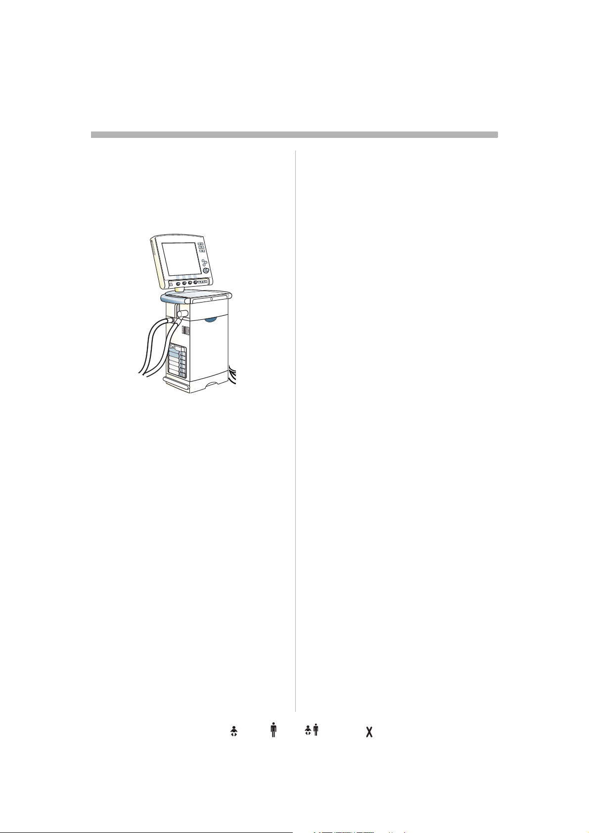
Brief device description
User
Interface
Patient
Patient
breathing
system
SVX-128_EN
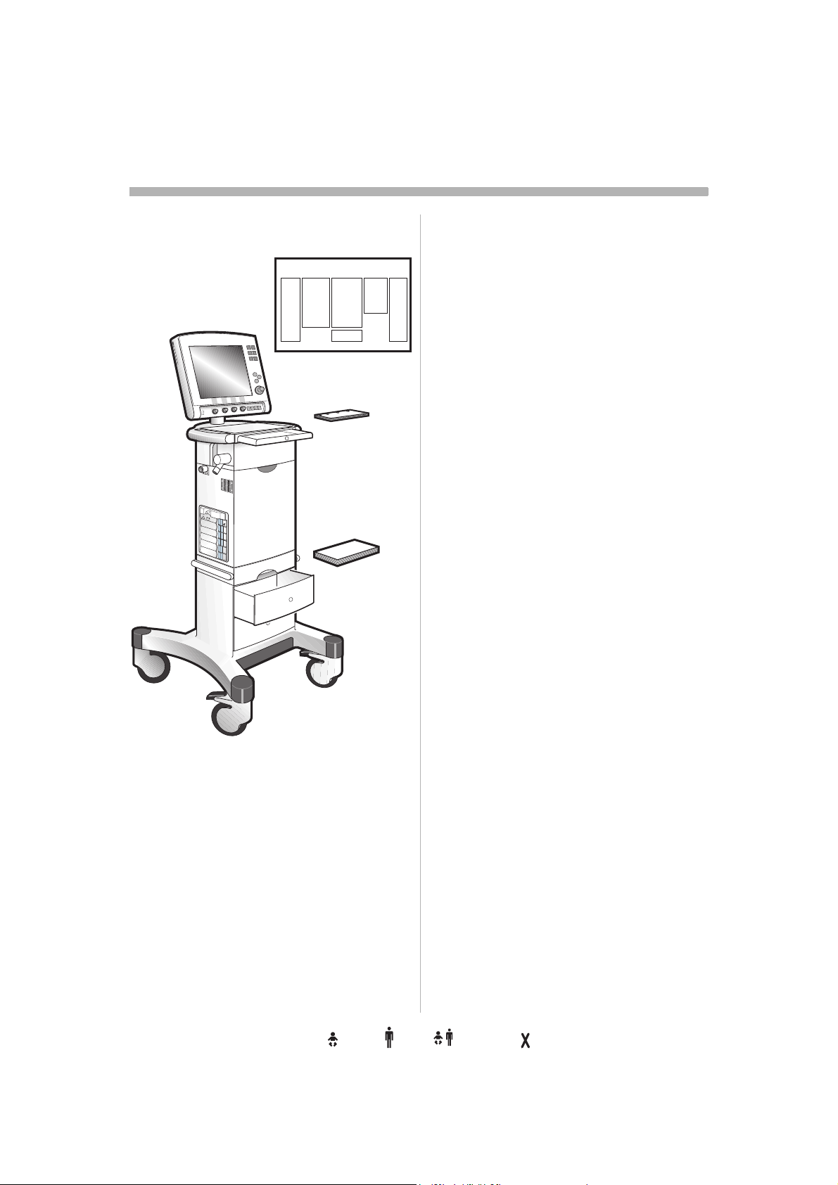
The Servo-i Ventilator System consists of a
Patient Unit where gases are mixed and
administered, and a User Interface where the
settings are made and ventilation is
monitored.
The ventilator delivers controlled or
supported breaths to the patient, with either
constant flow or constant pressure, using a
set oxygen concentration. The entire Servo-i
system includes a wide range of optional
accessories, e.g. Mobile Cart, breathing
systems, compressors, Battery modules,
humidifiers and equipment for nebulization,
CO
measurement and Y-piece
2
measurement.
Unit
Intended use
The Servo-i Ventilator System is intended for
treatment and monitoring of patients in the
range of neonates, infants and adults with
respiratory failure or respiratory insufficiency.
Note: The Servo-i Ventilator System is not
intended to be used with any anesthetic
agents.
professional health care providers who have
sufficient experience in ventilator treatment.
Intended population
The Servo-i Ventilator System can be
delivered in three configurations:
• Servo-i Infant range 0,5 - 30kg
NIV (PC+PS) Infant range 3 - 30kg
NIV Nasal CPAP range 0.5 - 10kg
• Servo-i Adult range 10 - 250kg
• Servo-i Universal range 0.5 - 250kg
NIV (PC+PS) Infant range 3 - 30kg
NIV Nasal CPAP range 0.5 - 10kg
Note: Servo-i Universal covers both Basic
and Extended edition.
Intended Use Environment
The SERVO-i ventilator system should be
used:
• in hospitals
• in facilities whose primary purpose is to
provide health care
• for in-hospital transport
• for interhospital transport if the conditions
stated in the Servo-i Interhospital
Transport declaration are fulfilled and an
agreement with MAQUET is signed.
• during MR examinations of patients if the
conditions in the Servo-i MR Environment
declaration are met and an agreement with
Maquet signed.
Warnings, Cautions and
Important in this manual
WARNING! Indicates critical information
about a potential serious outcome to the
patient or the user.
Caution: Indicates instructions that must be
followed in order to ensure the proper
operation of the equipment.
Intended user
Servo-i is a ventilator system with advanced
functionality. It may be used only by
4
Infant Adult Universal Option
Important: Indicates information intended to
help you operate the equipment or its
connected devices easily and conveniently.
Servo… User´s manual
US edition
Order No: 66 00 261
Page 7
Before use
1
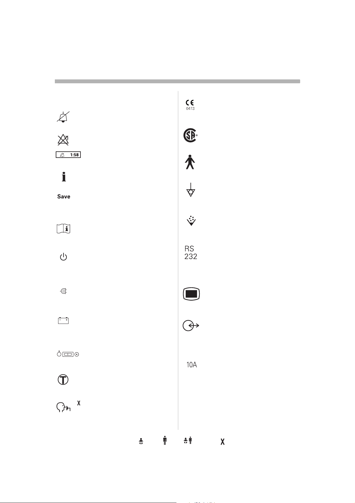
Symbols
User Interface
Audio off Silence alarm or confirm
alarm.
Alarm off .
Audio pause Silence alarm or
confirm alarm.
Reserved for future use.
Save To save a recording or to copy
screen.
Attention Consult accompanying
documents.
Standby/Start ventilation Set
standby mode or start ventilation.
Yellow lamp indicating Standby
mode.
Patient Unit
CE label The device complies with
the requirements of the Medical
Device Directive 93/42/EEC.
CSA label The device complies
with the Canadian standards.
C US
Class I equipment, Type B The
device classification according to
according to IEC 60601-1/EN 6060-1.
Equipotentiality terminal
Nebulizer
connector for nebulizer.
RS 232 / Serial port
connector for data communication
Note: The symbol has two different
labels depending on panel version.
Mains indicator
Green lamp indicating mains
connected.
Battery Symbol indicating battery
power supply.The estimated
remaining time with current power
consumption is indicated in minutes.
Trigger indication The indication
appears in the message/alarm field
when the patient triggers a breath.
The NIV symbol appears in the Mode
pad field during Non Invasive
Ventilation.
Servo… User´s manual
US edition
Order No: 66 00 261
ON/OFF switch
NIV symbol
User Interface connector / Panel
Note: The symbol has two different
labels depending on panel version.
Optional connector / Expansion
connector for optional equipment.
Note: The symbol has two different
labels depending on panel version.
10A
fuse for external DC power supply.
Infant Adult Universal Options
5
Page 8
s
Before use
1
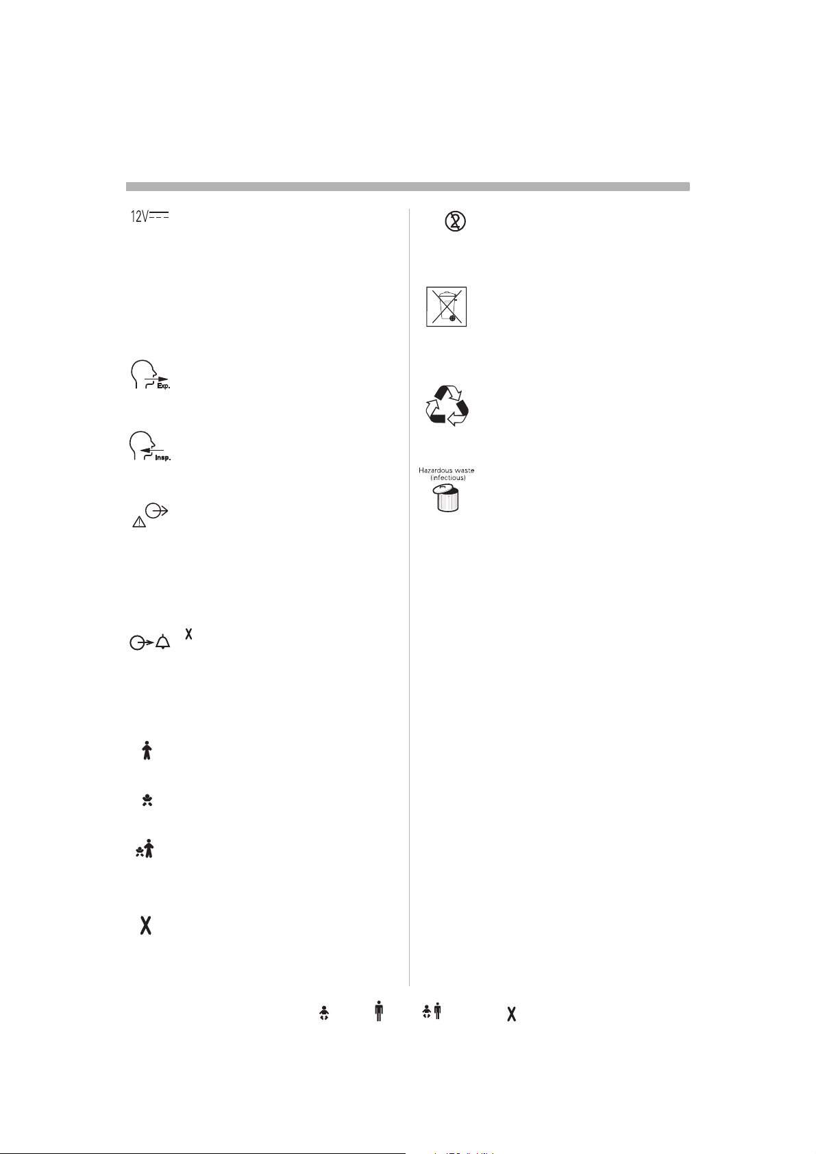
12V DC / Ext. bat 12V
external +12V DC inlet.
Note: The symbol has two different
labels depending on panel version.
Caution: When external +12 V DC
is used, at least one installed
Battery module is required to ensure
proper operation.
Expiratory label
Gas flow from patient.
Inspiratory label
Gas flow to patient.
Gas exhaust port label
Exhaust gas flow from ventilator.
Note: Should not be connected to a
spirometer, as the volume through
the exhaust port is not equal to the
expired volume from the patient.
Single use
Special waste
This product contains electronic
and electrical components.
Discard disposable, replaced and
left-over parts in accordance with
appropriate industrial and
environmental standards.
Recycling
Worn-out batteries must be
recycled or disposed of properly
in accordance with appropriate
industrial and environmental
standards.
Hazardous waste (infectious) The
device contains parts which must
not be disposed of with ordinary
waste.
Alarm output connection
option
External alarm output
communication.
In this manual
Adult Information valid for the Adult
configuration
Infant Information valid for the Infant
configuration
Universal (Basic and Extended
editions) Information valid for the
Universal configuration.
Options
6
Infant Adult Universal Option
Servo… User´s manual
US edition
Order No: 66 00 261
Page 9
Warnings, cautions and important
1
Support material related to
the Servo-i system
Wall cleaning diagram
Configuration Card
User‘s manual
This concept comprises components
intended to cover the needs of a clinical user.
It is divided into different components
according to use to facilitate accessibility of
information. If you have any comments or
suggestions regarding this information
material, please let us know.
This User´s manual covers functionality and
use but should not be regarded as all
inclusive within the very complex field of
ventilatory treatment. Clinical judgements or
settings are therefore not described in this
manual. Authorized, medically competent
health care providers with good knowledge
of Servo-i Ventilator System have the
responsibility to determine the clinical
judgement and settings based on the needs
of the patient.
Read the User´s manual carefully before use
and follow the instructions.
SVX-129_EN
Servo… User´s manual
US edition
Order No: 66 00 261
Infant Adult Universal Options
7
Page 10

s
Warnings, cautions and important
1
This User´s manual
The information in this User´s manual is valid
for Servo-i Ventilator System 3.1 unless
stated otherwise.
Here you will find the information needed to
use the Servo-i system safely.
It is divided into five main sections:
• Before use (mandatory information)
•Description
• Operation
• Maintenance
• Miscellaneous
Recommended use
The main document, for every-day use.
Text shown on the User Interface is presented
in these instructions in a special typeface.
Brief instructions
Overviews and step-by-step instructions for
the set-ups. These instructions you will find
in the drawer above the ventilator, when
positioned on the Mobile Cart.
Recommended use
These documents are intended to be used as
a guide for the experienced user.
Wall diagram
Overviews and step-by-step instructions for
cleaning, to be posted on a wall.
Recommended use
Checklist for the experienced user.
Ventilator - Information
material
Caution: The Servo-i Ventilator System may
have different software versions. Before use,
make sure the software version shown on the
screen under the Status / General menu
corresponds to the version number on the
User´s manual. Refer to page 259.
Trademark
Trademark ™ is written only when a product/
method name appears for the first time in this
manual.
8
Infant Adult Universal Option
Servo… User´s manual
US edition
Order No: 66 00 261
Page 11

Warnings, cautions and important
1
General warnings
• The Servo-i Ventilator System must be
operated only by authorized personnel
who are well trained in its use. It must be
operated according to the instructions in
this User´s manual.
• After unpacking, perform a Routine
cleaning and a Pre-use check.
• To provide adequate patient safety, set the
alarm limits to relevant values.
• To avoid electrical shock hazard, connect
the power cord to a mains outlet equipped
with a protective ground.
• Should any unfamiliar events occur, such
as irrelevant pop-up windows on the
screen, unfamiliar sounds, alarms from the
Patient Unit or technical high priority
alarms, the ventilator should immediately
be checked and, if applicable, replaced.
• Only accessories and auxiliary equipment
that meet current IEC standards (e.g. IEC
60601-1-1) may be connected to the
Servo-i Ventilator System. If external
equipment such as computers, monitors,
humidifiers or printers are connected, the
total system must comply with IEC 606011-1.
• The ventilator must only be used in an
upright position.
• When a Servo Ultra Nebulizer is used,
always consult the drug manufacturer
regarding the appropriateness of
ultrasonic nebulization for certain
medication.
• All personnel should be aware of the risk
of parts being infected when
disassembling and cleaning the ventilator.
• Service mode may only be used when no
patient is connected to the ventilator.
• Positive pressure ventilation can be
associated with the following adverse
events: barotrauma, hypoventilation,
hyperventilation or circulatory impairment.
• The Servo-i Ventilator System is verified
against and complies with IEC 60601-1-2
regarding electromagnetic compatibility. It
is the responsibility of the user to take
necessary measures to ensure that the
clinical environment is compatible with the
limits specified in IEC 60601-1-2.
Exceeding of these limits may impair the
performance and safety of the system.
Such measures should include, but are not
limited to:
– Normal precautions with regard to
relative humidity and conductive
characteristics of clothing in order to
minimize the build-up of electrostatic
charges.
– Avoiding the use of radio-emitting
devices, such as cellular phones and
high-frequency apparatus in close
proximity to the system.
• The SERVO-i Ventilator System may only
be used during MR examinations if the
conditions in the MR Environment
Declaration are met and an agreement
with Maquet is signed. Disregard of these
conditions may cause deactivation of the
system functions and may result in
permanent damage to the SERVO-i
Ventilator System.
• The Servo-i Ventilator System is not
intended to be used with any anesthetic
agent. To avoid risk of fire, flammable
agents such as ether and cyclopropane
must not under any circumstances be
used with this device.
Servo… User´s manual
US edition
Order No: 66 00 261
Infant Adult Universal Options
9
Page 12

s
Warnings, cautions and important
1
• To avoid fire hazard, keep all sources of
ignition away from the Servo-i Ventilator
System and oxygen hoses. Do not use
oxygen hoses that are worn, frayed, or
contaminated by combustible materials
such as grease or oils. Textiles, oils, and
other combustibles are easily ignited and
burn with great intensity in air enriched
with oxygen. Immediately disconnect the
ventilator from the oxygen supply, facility
power, and backup sources if there is a
smell of burning.
General cautions
• As a general rule always avoid contact
with external electrical connector pins. It is
recommended to have the module
compartment filled up with empty modules
to protect from spillage and dust.
• Federal law in the USA restricts this device
to sale by or on the order of a physician (or
a properly licensed practitioner).
• The Servo-i Ventilator System must be
serviced at regular intervals by specially
trained personnel. The intervals are stated
in the chapter Regular maintenance. Any
maintenance must be noted in a log book
for that purpose in accordance with
national regulations.
• MAQUET has no responsibility for the safe
operation of the equipment if service or
repair is done by a non-professional or by
persons who are not employed by or
authorized by MAQUET. We recommend
that service is done as part of a service
contract with MAQUET.
• MAQUET has no responsibility for the safe
operation of the equipment if the
equipment is used for anything other than
its intended use, as specified in this User´s
manual.
• A resuscitator should always be readily
accessible for extra safety.
• When connected to a patient, the system
must never be left unattended.
• The nebulizer module is inoperative when
the ventilator is running on batteries, to
reduce the power consumption.
• The Expiratory cassette must not be lifted
up when the ventilator is in operation. This
may, however, be done when in Standby
mode.
• Always use heat and moisture exchanger
(HME) or equipment to prevent
dehydration of lung tissue.
• Refer to the Installation instructions to
assemble the system or options to obtain
a proper mechanical assembly.
• When lifting or moving the ventilator
system or parts of the system, follow
established ergonomic guidelines, ask for
assistance, and take appropriate safety
precautions.
• Antistatic or electrically conductive
breathing tubing should not be used with
this lung ventilator system.
• Any scavenging system (Gas evac)
connected must comply to ISO8835-3
with regard to subatmospheric pressure
and induced flow. Otherwise ventilator
functions and patient safety may be
degraded.
• It is not recommended to use the Servo
Evac 180 in the Nasal CPAP mode.
• Values measured at the signal outputs of
the Servo-i Ventilator System and which
have been processed in auxiliary
equipment must not be used as a
substitute for therapeutic or diagnostic
decisions. Such decisions can be made
only by staff with medical expertise,
according to established and accepted
practice. If auxiliary equipment that has
not been delivered by MAQUET with the
system is used, MAQUET denies all
responsibility for the accuracy of signal
processing.
10
Servo… User´s manual
Infant Adult Universal Option
US edition
Order No: 66 00 261
Page 13

Warnings, cautions and important
1
• If there should be any deviation between
information shown on the User Interface of
the ventilator and that shown by the
auxiliary equipment, the ventilator
parameters shown on the User Interface
shall be considered the primary source for
information. When combining the Servo-i
Ventilator System with accessories and
auxiliary equipment other than those
recommended by MAQUET, it is the
responsibility of the user to ensure the
integrity of system performance and
safety. In order to maintain electrical
system safety, i.e. such that compliance
with IEC 60601-1-1 is fulfilled, only
accessories and auxiliary equipment that
meet current IEC standards (e.g. IEC
60601-1, IEC 950) may be connected to
signal inputs and outputs of the Servo-i
Ventilator System.
• Only original parts from MAQUET must be
used in the system.
• Only accessories, supplies or auxiliary
equipment recommended by MAQUET
should be used with the ventilator system
(“Products and accessories” catalog and
“Spare parts list”). Use of any other
accessories, spare parts or auxiliary
equipment may cause degraded system
performance and safety.
• The displayed information about set and
corresponding measured parameters,
shall continously be compared by the
operator.
Important:
• This symbol on the unit means
Attention, consult accompanying
documents.
Note: The are two versions of this symbol
depending on System version.
• The gases supplied must be free from
water, oil, particles and other
contaminants:
Air ........ H
O < 7 g/m
2
............. Oil < 0.5 mg/m
............. Chlorine: Must not be detectable
Oxygen H2O < 20 mg/m
3
3
3
• The environmental declaration is part of
the service manual.
• The Servo-i Ventilator system does not
contain any latex.
• Data on pressures can be given in cmH
where:
1 kPa ~ 10 cmH
100 kPa = 1bar ~1atm ~1kgf/cm
O
2
2
(kp/cm2)
100 kPa ~15 psi.
• All disposable parts must be discarded
according to hospital routine and in an
environmentally safe way.
• Do not expose the Expiratory cassette
compartment to excessive amounts of
fluid, e.g. during cleaning and disinfection,
as this may influence ventilator
functionality.
• Do not use sharp tools on the screen.
• It is recommended that at least two
batteries always is used in the ventilator for
backup.
• It is recommended that at least two
batteries are used for ventilation during
transport.
2
1
O,
Servo… User´s manual
US edition
Order No: 66 00 261
1. If the compressed air is generated by a
liquid ring compressor there is a potential
risk of chlorine in the supplied air.
Infant Adult Universal Options
11
Page 14

s
Warnings, cautions and important
1
• Documentation for Servo-i Ventilator
System consists of:
–User´s manual
– Brief instructions
– Wall diagram
– Installation instructions
– Service manual
– Products and accessories, catalog
– Spare parts list
Context-related warnings
Note: General warnings are not listed here
even though they are repeated inside the
manual.
Note: Context-related Cautions and
"Important" are not listed here, but are
written in the relevant context inside the
manual.
Operation
• Always disconnect the ventilator if any
operation which may involve risk for the
patient will be done, e.g. replacement of
O
cell, dismantling etc. (page 211,
2
page 225).
• If the trigger sensitivity is set too high, a
self-triggering (auto-triggering) condition
may be reached. This condition can also
be reached if there is leakage in the
breathing system, e.g. if an uncuffed
endotracheal tube is used. Triggering will
then be initiated by the system and not by
the patient.This should always be avoided
by decreasing the trigger sensitivity
(page 23). This is also important during
transport as the movement of the body
and the breathing system may lead to
false triggering.
• When you turn a Direct Access Knob,
ventilation will change accordingly from
the next breath without additional
confirmation (For further information see
page 166).
• If any malfunctions are detected during the
start-up procedure, please refer to
Chapter, Troubleshooting (page 225).
• If a malfunction persists, the ventilator
may not be connected to the patient.
• A Pre-use check must always be done
before connecting the ventilator to a
patient (page 145).
• To protect the patient against high airway
pressures, the upper pressure limit must
always be set to the relevant value so as to
provide adequate patient safety (page
165).
Caution: If airway pressure rises 6 cmH
above the set upper pressure limit the
safety valve opens. The safety valve also
opens if system pressure exceeds 117
cmH
O.
2
• To provide adequate patient safety, always
set the alarm limits at relevant values
(page 165).
O
2
± 7
12
Servo… User´s manual
Infant Adult Universal Option
US edition
Order No: 66 00 261
Page 15

Warnings, cautions and important
1
Nebulization
• Servo Humidifier/HME must be
disconnected during nebulization
otherwise the humidifier may be blocked
(page 128).
• The heated humidifier must be switched
off during nebulization. Otherwise the
particle size may be affected (page 128).
• During nebulization a filter must be
connected to the expiratory inlet of the
ventilator. Always carefully monitor the
airway pressure during nebulization.
Increased airway pressure could be
caused by a clogged filter. The filter should
be replaced if the expiratory resistance
increases or every 24 hours when the
nebulizer is being used.
• When a Servo Ultra Nebulizer is used,
always consult the drug manufacturer
regarding the appropriateness of
ultrasonic nebulization for certain
medications (page 128, 187).
• The nebulizer must not be used without
buffer liquid (sterile water). Otherwise the
ultrasonic generator crystal may break
(page 129, 187).
• To avoid explosion hazards, flammable
agents such as ether and cyclopropane
must not be used with this device. Only
agents which comply with the
requirements on non-flammable agents in
the IEC standard “Particular requirements
for electrical safety of anaesthetic
machines” are suitable.
• For adult/pediatric patients, never fill the
medication cup with more than 10 ml
(page 129).
• For neonatal patients, never fill the
medication cup with more than 4 ml
(page 129).
• If the patient unit of the nebulizer is tilted,
the drug can flow into the patient´s lungs
or the ventilator.
• The nebulizer must not be left unattended
when connected to a patient.
• Continuously check that the buffer liquid
level is between MIN. and MAX. during
nebulization (page 187).
• During nebulization: Continuously check
that moisture is generated in the
medication cup (page 187).
• When the ventilator is running on batteries
the nebulizer module is inoperative, to
reduce the power consumption
(page 187).
• For information about the stand alone
Aeroneb Professional Nebulizer System,
refer to separate manual.
Cleaning
• All personnel should be aware of the risk
of parts being infected when
disassembling and cleaning the ventilator
(page 191).
• After removing the Expiratory cassette, do
not pour any fluid into the Expiratory
cassette compartment (page 196).
Replacement of O2 cell
The sealed unit of the O2 cell, contains a
caustic liquid which may cause severe burns
to the skin and eyes. In case of contact,
immediately flush continuously with water for
at least 15 minutes and seek medical
attention especially if the eyes are affected
(page 214)
Servo… User´s manual
US edition
Order No: 66 00 261
Infant Adult Universal Options
13
Page 16

1
s
Notes
..................................................................
..................................................................
..................................................................
..................................................................
..................................................................
..................................................................
..................................................................
..................................................................
..................................................................
..................................................................
..................................................................
..................................................................
..................................................................
..................................................................
..................................................................
..................................................................
..................................................................
..................................................................
..................................................................
..................................................................
..................................................................
..................................................................
..................................................................
..................................................................
14
Infant Adult Universal Option
..................................................................
..................................................................
..................................................................
..................................................................
..................................................................
..................................................................
Servo… User´s manual
US edition
Order No: 66 00 261
Page 17

2. Ventilation
Contents
Modes of ventilation. . . . . . . . . . . . . . . . . . . . . . . 16
Important definitions . . . . . . . . . . . . . . . . . . . . . . 21
Trigger sensitivity . . . . . . . . . . . . . . . . . . . . . . . . . 23
Settings . . . . . . . . . . . . . . . . . . . . . . . . . . . . . . . . 25
Special functions . . . . . . . . . . . . . . . . . . . . . . . . . 29
Controlled ventilation - PRVC . . . . . . . . . . . . . . . 32
Controlled ventilation - Volume Control . . . . . . . . 35
Controlled ventilation - Pressure Control . . . . . . . 38
Supported ventilation - Volume Support . . . . . . . 40
Supported ventilation - Pressure Support . . . . . . 43
Spontaneous/CPAP . . . . . . . . . . . . . . . . . . . . . . . 46
Automode. . . . . . . . . . . . . . . . . . . . . . . . . . . . . . . 48
SIMV. . . . . . . . . . . . . . . . . . . . . . . . . . . . . . . . . . . 52
Bi-Vent . . . . . . . . . . . . . . . . . . . . . . . . . . . . . . . . . 59
Non Invasive Ventilation (NIV) . . . . . . . . . . . . . . 61
NIV - Pressure Control . . . . . . . . . . . . . . . . . . . . . 62
NIV - Pressure Support . . . . . . . . . . . . . . . . . . . . 63
NIV - Nasal CPAP. . . . . . . . . . . . . . . . . . . . . . . . . 64
Open Lung Tool . . . . . . . . . . . . . . . . . . . . . . . . . . 65
Ventilatory parameters, overview . . . . . . . . . . . . . 66
Servo… User´s manual
US edition
Order No: 66 00 261
Infant Adult Universal Options
15
Page 18
s
Modes of ventilation
2
Ventilatory management
The Servo-i Ventilator System is designed for
safe and effective treatment. It can be set for
continuous adaptation to the patient´s
prevailing condition or for manually
controlled operations. The servo systems for
pressure, flow and timing operate in all
modes of ventilation (set time in control
modes and patient-related timing in support
modes).
Important:
• To show all available installed ventilation
modes, please refer to "Setting ventilation
mode" on page 164 in this manual.
• In all pressure controlled modes, it is
important to set alarm limits to adequate
levels.
• For information about default values and
parameter settings refer to page 249.
Application
The Servo-i ventilator system also contains
tools to assist the user in application of lung
recruitment methodologies.
Scope - ventilatory needs
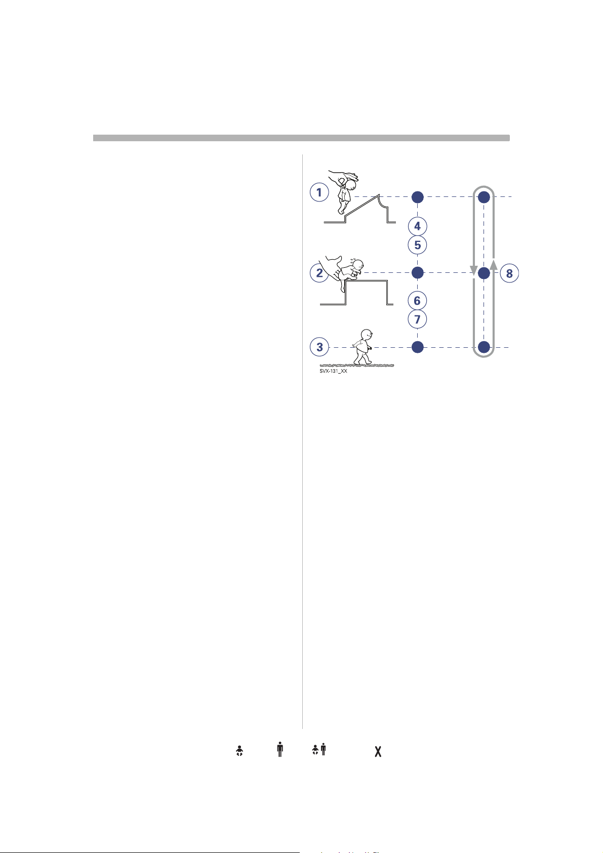
The ventilator can be used for true:
1. controlled ventilation
2. supported ventilation, or
3. spontaneous breathing/CPAP
4-7. It also allows for combined ventilatory
control or support. Spontaneous breathing
efforts are sensed during controlled
ventilation, e.g. Volume Control. Mandatory
ventilation can be used during supported/
spontaneous breathing, e.g. the enhanced
SIMV functionality.
8. The Automode functionality continuously
adapts to the patient´s breathing capability.
When required, all ventilation is provided for
mandatorily. When the patient is able to
initiate a breath, the ventilator supports and
monitors the patient´s breathing capability
and controls ventilation only if required.
16
Servo… User´s manual
US edition
Infant Adult Universal Option
Order No: 66 00 261
Page 19
Modes of ventilation
2
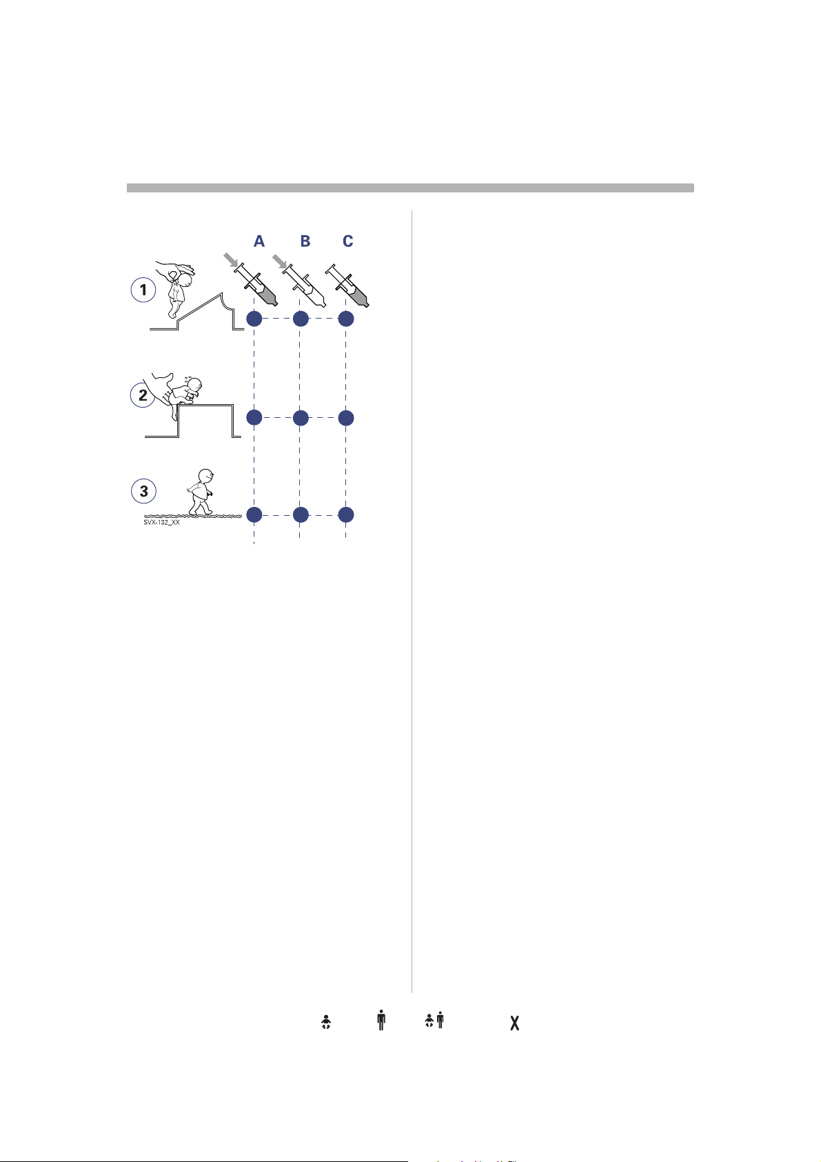
Implementation
Ventilation can be managed and
administered with a focus on:
A. pressure and volume
B. pressure
C. flow/volume.
Extra flow and extra breaths
In flow/volume- oriented modes of
ventilation, additional on-demand flow can
be triggered during inspiration. Additional
breaths can always be triggered between the
ordinary breaths if the set trigger criteria are
met.
Timing
In controlled ventilation modes, timing is
related to preset values. In supported
ventilation modes, timing is related to patient
triggering and Inspiratory cycle-off setting.
Pressure and volume in focus
In the pressure- and flow- oriented modes, a
constant inspiratory Tidal Volume is
maintained. The inspiratory pressure level is
constant during each breath. (PRVC, Volume
Support.)
Pressure in focus
In the pressure-oriented modes, a constant
preset pressure level is maintained during
inspiration. (Pressure Control, Pressure
Support)
Flow/volume in focus
In the flow/volume oriented modes a
constant inspiratory volume is maintained.
The inspiratory flow is constant during each
breath (Volume Control).
Servo… User´s manual
US edition
Order No: 66 00 261
Infant Adult Universal Options
17
Page 20
s
Modes of ventilation
2
Basic functionality - An overview
18
Servo… User´s manual
US edition
Infant Adult Universal Option
Order No: 66 00 261
Page 21

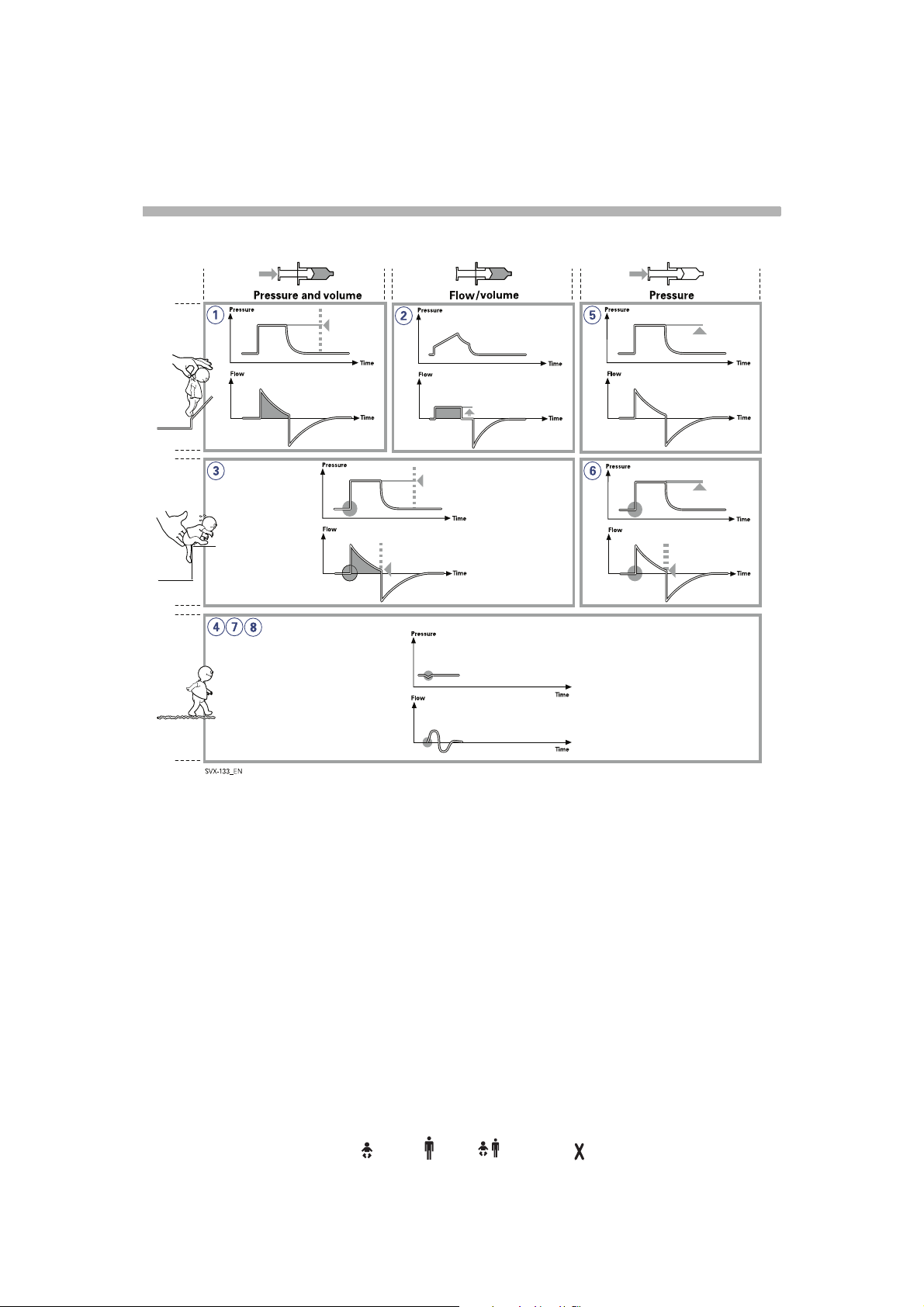
1.(PRVC) Pressure Regulated
Volume Control
Breaths are delivered mandatorily to assure
preset volumes, with a constant inspiratory
pressure continuously adapting to the
patient´s condition. The flow pattern is
decelerating.
2. Volume Control
Breaths are delivered mandatorily with a
constant flow to assure preset volumes.
3. Volume Support
A patient-adapted constant inspiratory
support is supplied when activated by
patient effort. The resulting volume is
continuously monitored and the constant
inspiratory pressure automatically adjusts to
the required level. The patient determines
frequency and duration of the breaths which
show a decelerating flow pattern.
4. Spontaneous breathing (CPAP)
When sufficient inspiratory volumes are
achieved, spontaneous breathing without
ventilator support is allowed for in Volume
Support.
5. Pressure Control
Breaths are delivered mandatorily at a preset
pressure level, causing a decelerating flow
pattern.
6. Pressure Support
Inspiration is supported by a constant preset
pressure when activated by patient effort.
The patient determines frequency and
duration of the breaths, which show a
decelerating flow pattern. Inspiratory breath
duration can be influenced by adjusting the
Inspiratory cycle-off criteria.
7. Spontaneous breathing/CPAP
True spontaneous breathing (CPAP) occurs
when the inspiratory pressure level is set to
zero in Pressure Support.
8. Nasal CPAP
Spontaneous breathing on a set pressure
level.
Modes of ventilation
2
Servo… User´s manual
US edition
Order No: 66 00 261
Infant Adult Universal Options
19
Page 22

s
Modes of ventilation
2
Combined modes - An
overview
Automode
The ventilator continuously adapts to the
patient's breathing capability and allows the
patient to better interact with the ventilator.
The ventilator automatically shifts between
controlled ventilation, supported ventilation
and spontaneous ventilation. Each
controlled ventilation mode has a
corresponding support mode.
Volume Control <----> Volume Support
PRVC <----> Volume Support
Pressure Control <----> Pressure Support
When the patient is making a breathing
effort, the ventilator immediately switches to
a support mode of ventilation. If the patient is
not making any breathing effort, the
ventilator will return to the controlled mode
and deliver controlled breaths.
Synchronized intermittent
Mandatory ventilation (SIMV)
The ventilator provides mandatory breaths
which are synchronized with the patient´s
spontaneous efforts at a preset rate. The
mandatory breaths can be Volume Control,
Pressure Control or PRVC breaths.
Bi-Vent
Bi-Vent is pressure controlled breathing,
giving the patient the opportunity of
unrestricted spontaneous breathing. Two
pressure levels are set together with the
individually set duration of each level.
Spontaneous efforts can be assisted by
pressure support.
20
Servo… User´s manual
US edition
Infant Adult Universal Option
Order No: 66 00 261
Page 23
Important definitions
2
x
V
V
ServoS-0046_XX
z
y
I:E
The graphic display of flow, pressure and
volume is visualized in wave forms. Modes of
ventilation directly affect flow, pressure and
volume patterns.
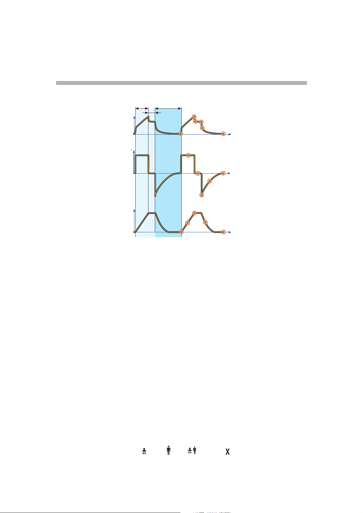
Volume Control
Pressure-Time waveform. Points
and regions of interest
X. Inspiration time
Y. Pause time
Z. Expiration time
1. Start of Inspiration
2. Peak inspiratory pressure
3. Early inspiratory pause pressure
4. End inspiratory pause pressure
5. Early expiratory pressure
6. End expiratory pressure
2
4
3
1
12
5
7
8
14
13
6
t
11
t
10
9
15
16
t
Flow-Time waveform. Points and
regions of interest
X. Inspiration time
Y. Pause time
Z: Expiration time
7. Peak inspiratory flow
8. Zero flow phase
9. Peak expiratory flow
10. Slope decelerating expiratory limb
11. End expiratory flow
Volume-Time waveform. Points
and regions of interest
X. Inspiration time
Y. Pause time
Z. Expiration time
12. Start of inspiration
13. The slope represents current delivery of
inspiratory tidal volume
14. End inspiration
15. The slope represents current patient
delivery of expiratory tidal volume
16. End expiration
Servo… User´s manual
US edition
Order No: 66 00 261
Infant Adult Universal Options
21
Page 24
s
Important definitions
2
P
V
ServoS-0047_XX
X
Z
I:E
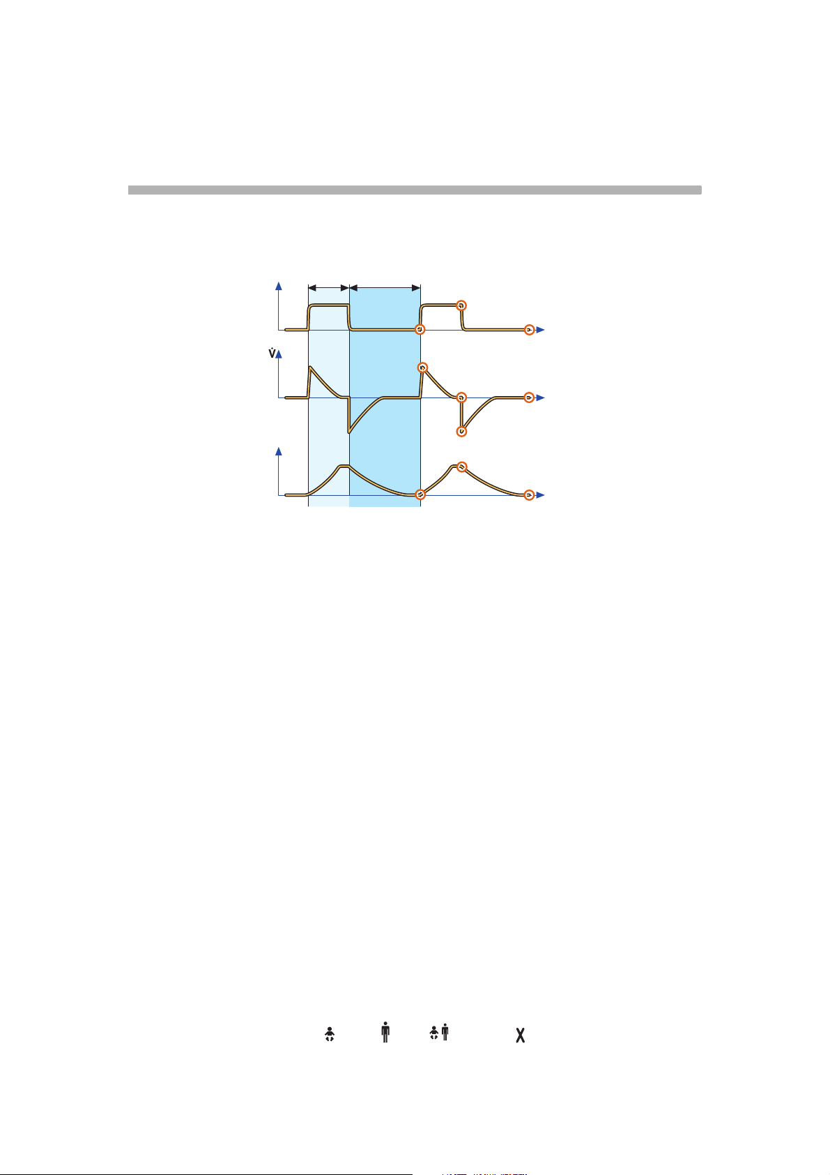
Pressure Control
Pressure-Time waveform. Points
and regions of interest
X. Inspiration time
Z. Expiration time
1. Start of Inspiration
2. Peak inspiratory pressure
3. End expiratory pressure
2
1
4
5
6
9
8
3
t
7
t
10
t
Volume-Time waveform. Points
and regions of interest
X. Inspiration time
Z.: Expiration time
8. Start of inspiration
9. End inspiration
10. End expiration
Flow-Time waveform. Points and
regions of interest
X. Inspiration time
Z. Expiration time
4. Peak inspiratory flow
5. End inspiratory flow
6. Peak expiratory flow
7. End expiratory flow
22
Infant Adult Universal Option
Servo… User´s manual
US edition
Order No: 66 00 261
Page 25
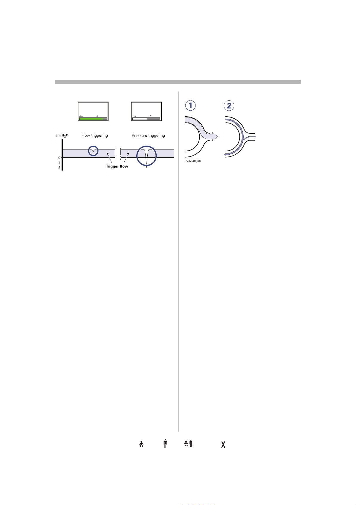
Trigger functionality
Trigg. Flow
5
Trigg. Pressure
-2
T rig g e r s e n s itiv it y
2
SVX-638_EN
This determines the level of patient effort to
trigger the ventilator to inspiration.
Trigger sensitivity can be set in flow
triggering (Trigg. Flow) or pressure triggering
(Trigg. Pressure). Normally flow triggering is
preferable as this enables the patient to
breath with less effort.
The sensitivity is set as high as possible
without self-triggering. This ensures that
triggering is patient initiated and avoids autocycling by the ventilator.
Pressure triggering can be set in the range
-20 to 0 cmH
level, white area on the bar).
O (in reference to set PEEP
2
When the trigger sensitivity is set above 0
(green and red area on the bar), flow
triggering is set, i.e. the amount of the bias
flow that the patient has to inhale to trigg a
new breath. The sensitivity can be set from
100% of the bias flow (left), to 0% of the bias
flow (right). For information about the
different colors of the bar refer to page 167.
Important: In
NIV it is not possible to set
trigger sensitivity.
The ventilator continuously delivers a gas
flow during expiration, which is measured in
the expiratory channel.
1. Inspiration.
Bias flow during expiration.
2. Bias flow Infant 0.5 l/min.
Bias flow: Adult 2 l/min.
Servo… User´s manual
US edition
Order No: 66 00 261
Infant Adult Universal Options
23
Page 26
s
Trigger sensitivity
2
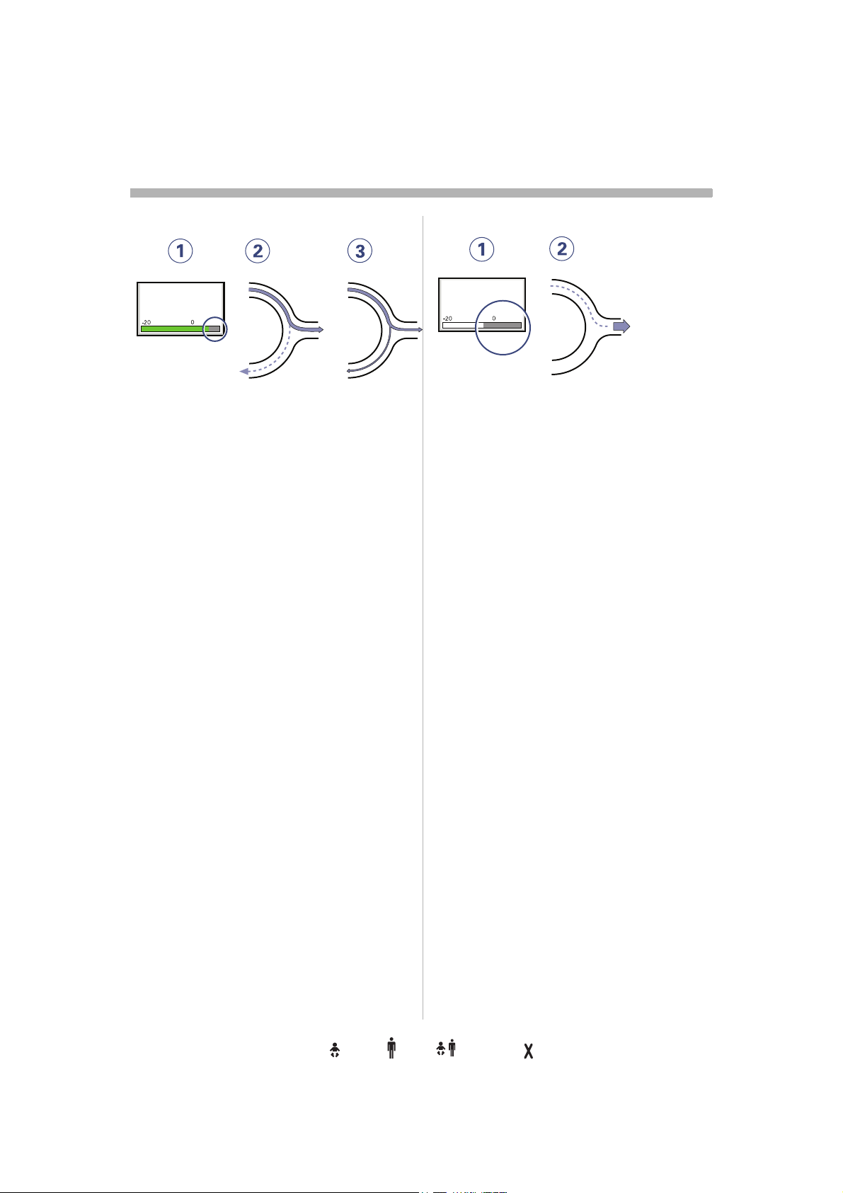
Weak patient effort
Trigg. Flow
5
SVX-141_EN
1. At a Trigger sensitivity level above zero
(0), the ventilator senses deviations in
the bias flow caused by inspiratory
efforts of the patient. The more to the
right on the scale, the more sensitive is
the trigger function.
2. Weak inspiratory effort.
3. Very weak inspiratory effort.
For further information see page 167.
WARNING! If the trigger sensitivity is set too
high, a self triggering (auto-triggering)
condition may be reached. This condition
can also be reached if there is leakage in the
breathing system, e.g. if an uncuffed
endotracheal tube is used. Triggering will
then be initiated by the system and not by the
patient.This should always be avoided by
decreasing the trigger sensitivity.
Stronger patient effort
Trigg. Pressure
-2
SVX-142_EN
1. At a Trigger sensitivity level below zero
(0), the ventilator senses negative
pressures created by the patient.
Required preset negative pressure to
initiate a breath is shown numerically.
The more to the left on the scale, the
more effort is required to trigger.
2. Stronger patient effort.
For further information see page 167.
WARNING! The trigger sensitivity bar has
different colors based on the setting. A green
bar indicates a normal setting for the flow
triggering. The risk of self-triggering
increases when the bar is red. A white bar
indicates that pressure triggering is required.
24
Servo… User´s manual
US edition
Infant Adult Universal Option
Order No: 66 00 261
Page 27
Settings
2
Inspiratory rise time
Insp rise time
P
0
100 %
0
SVX-644_EN
Time to peak inspiratory flow or pressure at
the start of each breath as a percentage of
the respiratory cycle time or in seconds.
Increased rise time will affect the rate of flow/
pressure increase and can be evaluated by
the shape of the flow and pressure
waveforms.
Inspiratory rise time (%) is applicable in
Pressure Control, Volume Control, PRVC,
SIMV-Volume Control, SIMV-Pressure
Control, SIMV-PRVC. Setting can be in the
range 0-20% of the respiratory cycle time.
Inspiratory rise time set in seconds is
applicable in Pressure Support, Volume
Support and Bi-Vent. For adults the range is
0-0.4 seconds and for infants the range is 0-
0.2 seconds.
Note: When the ventilator is configured for
setting of Inspiration time, the unit for
Inspiratory rise time then automatically
switches to seconds for all ventilation
modes.
t
t
Inspiratory cycle-off
SVX-205_XX
Inspiratory Cycle-off is the point at which
inspiration changes to expiration in
spontaneous and supported modes of
ventilation. A decrease of the inspiratory flow
to a preset level causes the ventilator to
switch to expiration. This preset level is
measured as a percentage of the maximum
flow during inspiration. The range of
Inspiratory cycle-off is 1 - 70%.
Note: In NIV the range is 10-70%.
Normally in supported modes the Inspiratory
rise time should be increased from the
default setting and so give more comfort to
the patient.
Servo… User´s manual
US edition
Order No: 66 00 261
Infant Adult Universal Options
25
Page 28
s
Settings
2
Breath cycle time
This is the length of the breath i.e. the total
cycle time of the mandatory breath in SIMV
(inspiration, pause plus expiration). This is
set in seconds within the range:
Infants: 0,5 -15 seconds in half second steps.
Adults: 1-15 seconds in one second steps.
Note: The soft key Breath cycle time is not
shown when an SIMV mode is selected and
inspiration time is configured. Refer to
heading I:E ratio / Inspiration times.
Trigger timeout
Trigger Timeout is the maximum allowed
apnea time in Automode before controlled
ventilation is activated. It is applicable in:
Automode:
Volume Control
PRVC
Pressure Control
The settings are within the ranges:
• Infant: 3-15 seconds
• Adult: 7-12 seconds
Initially the ventilator adapts with a dynamic
Trigger Timeout limit. This means that for the
spontaneously triggering patient the timeout
increases successively during the first ten
breaths.
<--->Volume Support
<--->Volume Support
<--->Pressure Support
PEEP
PEEP
SVX-646_EN
Positive End Expiratory Pressure (PEEP) can
be set in the range of 0 - 50 cmH
Positive End Expiratory Pressure is
maintained in the alveoli and may prevent the
collapse of the airways.
Note: In NIV the range is 2-20 cmH
O. A
2
2
O.
26
Servo… User´s manual
US edition
Infant Adult Universal Option
Order No: 66 00 261
Page 29

Settings
2
I:E ratio / Inspiration time
The setting of breathing parameters in
Servo-i can be configured in two different
ways, based on:
• I:E ratio (independent of changes of e.g.
the breathing frequency) or,
• Inspiration time in seconds (independent
of changes of e.g. the breathing
frequency), to better meet the
requirements for infant care.
When the ventilator is configured for setting
of Inspiration time, the unit for Pause time
and Insp. rise time then automatically
switches to seconds. The resulting I:E ratio
for each setting is shown in the upper right
information area of the ventilation mode
window.
As the inspiration time is explicitly set, a
change of for example the Respiratory Rate
will affect the I:E ratio. As a safety precaution,
it will therefore be indicated when the
resulting I:E ratio passes 1:1 in either
direction.
Note: The soft key Breath cycle time is not
shown when an SIMV mode is selected,
since there is no need to set Breath cycle
time when Inspiration time is directly set.
Note: The configuration is done by a service
technician with a service card.
Volume setting
Depending on the ventilator configuration the
inspiratory volume can be set as:
– Minute Volume or,
– Tidal Volume
Note: The configuration is done by a service
technician with a service card.
Controlled / supported
pressure level
PC (Pressure Control level) above PEEP is
the set inspiratory pressure level for each
mandatory breath in Pressure Control and
SIMV (PC) + PS, and also for Apnea back-up
in Pressure Support.
PS (Pressure Support level) above PEEP is
the set inspiratory pressure support level for
triggered breaths in Pressure Support, SIMV
modes and Bi-Vent.
O2 concentration
The setting range for the gas mixer is 21% O2
to 100% O
automatically set at approximately 6% O2
above or below the set concentration value.
There is also an absolute minimum alarm
limit of 18% O
operating settings.
. The alarm limits are
2
which is independent of
2
Respiratory rate / SIMV
frequency
Respiratory rate is the number of controlled
mandatory breaths per minute in controlled
modes excluding SIMV. The respiratory rate
is also used for calculation of tidal volume if
the ventilator is configured for Minute volume
setting. SIMV rate is the number of controlled
mandatory breaths in SIMV modes.
Servo… User´s manual
US edition
Order No: 66 00 261
Infant Adult Universal Options
27
Page 30
s
Settings
2
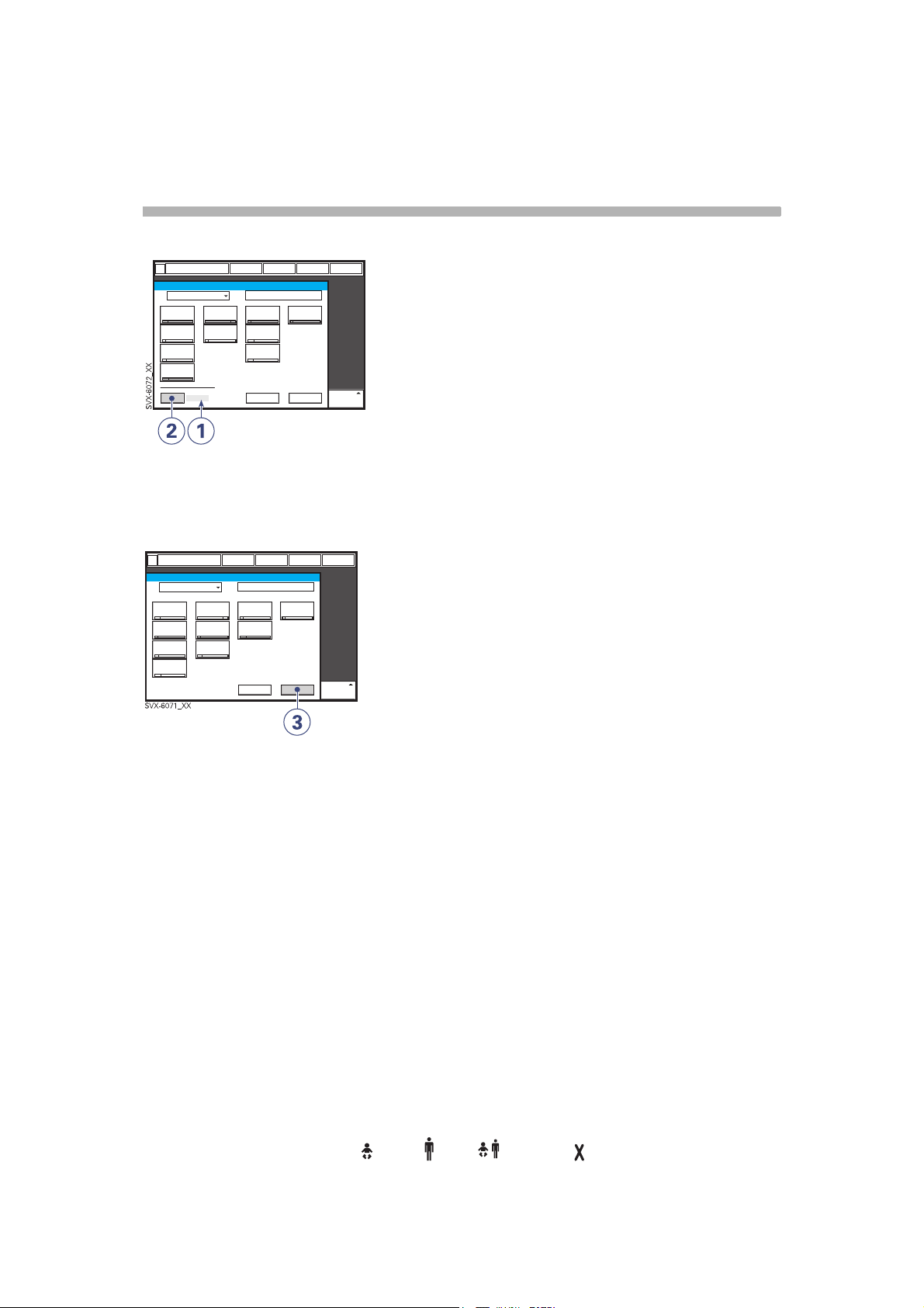
Previous ventilation mode
1. Time when previous mode was
inactivated.
2. Press the pad Show previous mode to
recall the previous accepted ventilation
mode.
3. Activate the previous used ventilation
mode settings by pressing the Accept
pad.
Note:
• The previous ventilation mode function is
not available after a Pre-use check,
changing of patient category, admitting a
new patient, use of the same ventilation
mode for more than 24 hours or after startup (cold start) of the system.
• In backup ventilation, the ventilator shows
the settings for the supported mode when
previous mode is activated.
• A recall of previous settings is only
possible after a change of ventilation
mode.
28
Infant Adult Universal Option
Servo… User´s manual
US edition
Order No: 66 00 261
Page 31

Special functions
2
Fixed keys
1. Start breath
2. O
breaths
2
3. Expiratory hold
4. Inspiratory hold
can all be chosen by manually pressing the
respective fixed key.
Start breath
The ventilator will initiate a new breath cycle
according to the current ventilator settings.
Servo… User´s manual
US edition
Order No: 66 00 261
Infant Adult Universal Options
29
Page 32

s
Special functions
2
O2 breaths
This function allows 100% oxygen to be
given for 1 minute. After this time the oxygen
concentration will return to the pre-set value.
The oxygen breaths can be interrupted by
repressing the O
the 1 minute interval.
breaths fixed key during
2
Expiratory hold
Expiratory and inspiratory valves are closed
after the expiration phase is completed, for
as long as the fixed key is depressed, up to a
maximum of 30 seconds. Expiratory hold
provides an exact measurement of the end
expiratory pause pressure. It can be used for
static compliance measuring and to
determine the total PEEP. The dynamic
pressure is shown on the PEEP numerical
value.
30
Servo… User´s manual
US edition
Infant Adult Universal Option
Order No: 66 00 261
Page 33

Special functions
2
Inspiratory hold
Inspiratory hold is activated by manually
pressing the fixed key. The maximum time is
30 seconds. The inspiratory and expiratory
valves close after inspiration. This function
can provide an exact measurement of the
end inspiratory lung pressure. It can be used
during x-ray or to determine Plateau
pressure, or static compliance calculation.
Back-up ventilation
Pressure support/
CPAP
Apnea
Volume support
SVX-647_EN
Back-up ventilation is available in all support
modes (not applicable in Automode and NIV
Pressure Support mode).
The Back-up function switches Volume
Support to Volume Control, Pressure
Support and CPAP to Pressure Control.
During Back-up ventilation default settings
are used for I:E ratio, Respiratory Rate, and
Inspiratory rise time. Apnea alarm can be set
in infant mode (5-45 seconds) and in adult
mode (15-45 seconds). The Back-up
pressure level is adjustable, minimum
settable value is 5 cmH
Note: Back-up not applicable in NIV Nasal
CPAP.
O.
2
Pressure control
Volume control
Servo… User´s manual
US edition
Order No: 66 00 261
Infant Adult Universal Options
31
Page 34

s
Controlled ventilation - PRVC
2
Functional description PRVC
The Pressure Regulated Volume Control
(PRVC) mode is a controlled breathing mode.
Servo-i Ventilator can be configured to set
Tidal Volume or Minute Volume. The
following parameters are set:
1. Tidal Volume (ml) or Minute Volume (l/
min)
2. Respiratory Rate (b/min)
3. PEEP (cmH
4. Oxygen concentration (%)
5. I:E ratio / Insp. time
6. Inspiratory rise time (%/s)
7. Trigg. Flow / Trigg. Pressure
O)
2
The ventilator delivers a pre-set Tidal
Volume. The pressure is automatically
regulated to deliver the pre-set volume but
limited to 5 cmH
pressure limit.
The flow during inspiration is decelerating.
The patient can trigger extra breaths.
O below the set upper
2
32
Servo… User´s manual
US edition
Infant Adult Universal Option
Order No: 66 00 261
Page 35

PRVC in detail
Controlled ventilation - PRVC
2
1
SVX-9006_XX
1. PRVC assures a set target minute
ventilation to the patient. The target
volume is based upon settings for Tidal
Volume, frequency and inspiration time.
2. The inspiratory pressure level is constant
during each breath, but automatically
adapts in small increments breath-bybreath to match the patient´s lung
mechanical properties for target volume
delivery.
3. Inspiration starts according to a preset
frequency or when the patient triggers.
Expiration starts:
a. After the termination of preset
inspiration time
b. If the upper pressure limit is
exceeded.
2
3
Servo… User´s manual
US edition
Order No: 66 00 261
Infant Adult Universal Options
33
Page 36

s
Controlled ventilation - PRVC
2
SVX-697_EN
The first breath of a start sequence is a
volume-controlled test breath with Pause
time set to 10%. The measured pause
pressure of this breath is then used as the
pressure level for the following breath. An
alarm is activated if the pressure level
required to achieve the set target volume
cannot be delivered due to a lower setting of
the upper pressure limit (- 5 cmH
2
O).
34
Servo… User´s manual
US edition
Infant Adult Universal Option
Order No: 66 00 261
Page 37

Controlled ventilation - Volume Control
Functional description
Volume Control
2
Volume Controlled ventilation ensures that
the patient receives a certain pre-set Minute/
Tidal Volume.
Servo-i Ventilator can be configured to set
Tidal Volume or Minute Volume. The
following parameters are set:
1. Tidal Volume (ml) or the Minute Volume
(l/min)
2. Respiratory Rate (b/min)
3. PEEP (cmH
4. Oxygen concentration (%)
5. I:E ratio / Insp. time
6. Pause time (%/s)
7. Inspiratory rise time (%/s)
8. Trigg. Flow / Trigg. Pressure
O)
2
The airway pressure is dependent on the
tidal volume, inspiration time and the
resistance and compliance of the respiratory
system. The set tidal volume will always be
delivered. An increase in the resistance and
decrease in compliance will lead to an
increased airway pressure. To protect the
patient's lungs from excessive pressure, it is
very important to set the upper pressure limit
to a suitable value.
It is possible for the patient to trigger extra
breaths if they can overcome the pre-set
trigger sensitivity. It is also possible for the
patient, by their own inspiratory efforts, to
receive a higher inspiratory flow and Tidal
Volume during an inspiration than pre-set.
The flow during inspiration is constant. The
patient can trigger extra breaths.
Servo… User´s manual
US edition
Order No: 66 00 261
Infant Adult Universal Options
35
Page 38

s
Controlled ventilation - Volume Control
2
Volume Controlled ventilation has, by
tradition, delivered each breath with a
constant flow and constant inspiratory and
expiratory times, according to the settings.
The Servo-i gives the possibility to the
patient to modify both flow rate and timing.
So, if a pressure drop of 3 cmH
during inspiration, the ventilator cycles to
O is detected
2
Pressure Support with a resulting increase in
inspiratory flow. When the flow decreases to
the calculated target level this flow will be
maintained until the set Tidal Volume is
delivered.
SVX-652_EN
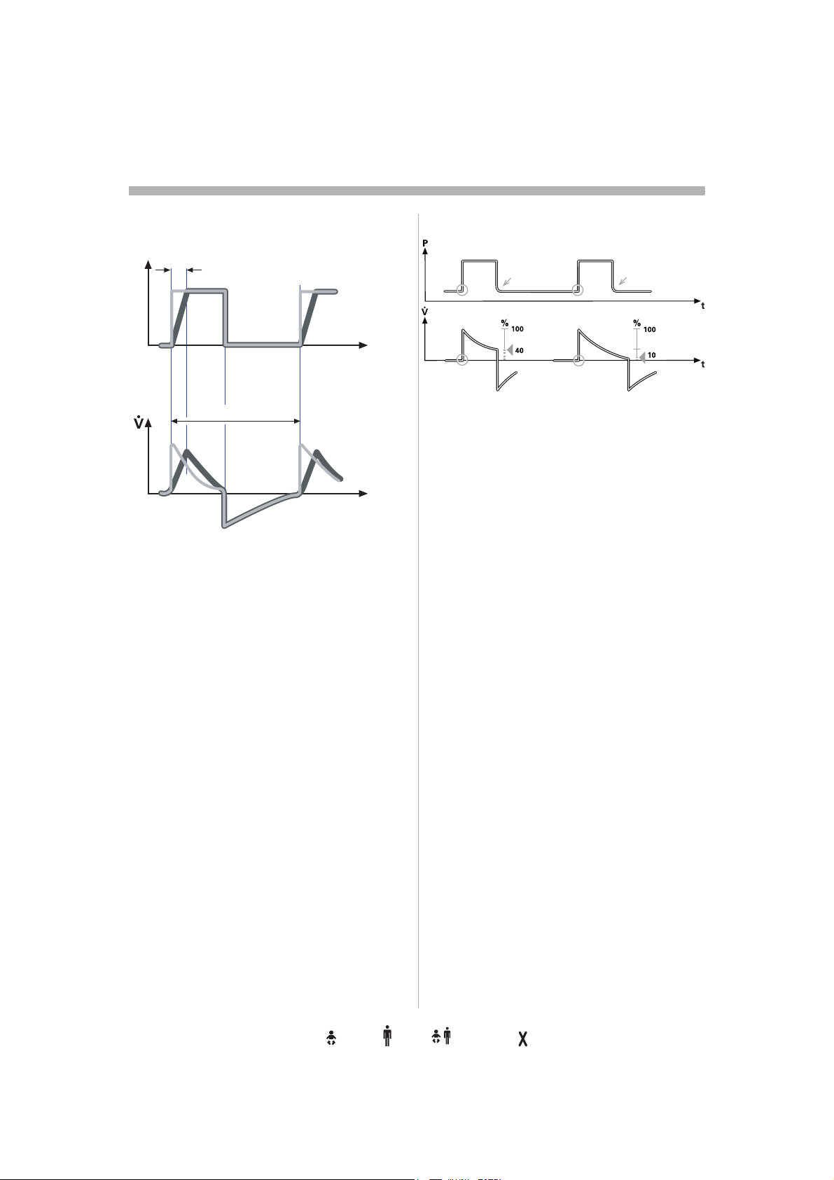
The waveform illustrations above show some
practical consequences of this enhanced
functionality.
• the top waveform shows the trace for a
normal Volume Controlled breath
• the second waveform shows a situation
when inspiration is prematurely interrupted
as the set tidal volume has been delivered
• the third waveform shows a situation
where the patient maintains a flow rate
higher than the calculated target value.
The set Tidal Volume has been delivered
when calculated target flow is reached and
the inspiration is prematurely interrupted
• the bottom waveform, shows a situation
where the increased flow rate is
maintained into the expiratory period. The
patient will receive a higher tidal volume
than set due to a higher flow/volume
demand than calculated.
36
Servo… User´s manual
US edition
Infant Adult Universal Option
Order No: 66 00 261
Page 39

Controlled ventilation - Volume Control
Volume Control in detail
2
SVX-9002_XX
1. Volume Control assures a preset tidal
volume with constant flow during a
preset inspiratory time at a preset
frequency.
2. The inspiratory flow is constant and
depends on User Interface setting.
3. Inspiration starts according to the preset
frequency or when the patient triggers.
4. If the patient makes an inspiratory effort
during the inspiratory period, the
ventilator will switch to Pressure Support
to satisfy the patient´s flow demand.
Expiration starts:
a. When the preset tidal volume is
delivered and after the preset pause
time.
b. When the flow returns to the set value
after the preset tidal volume is
delivered and after the preset pause
time (on-demand support). The
patient is however always guaranteed
an expiration time corresponding to at
least 20% of the total breath.
c. If the upper pressure limit is
exceeded.
1 2
3
4
Servo… User´s manual
US edition
Order No: 66 00 261
Infant Adult Universal Options
37
Page 40

s
Controlled ventilation - Pressure Control
2
Functional description
Pressure Control
The Pressure Controlled mode is a controlled
breathing mode.
The following parameters are set:
1. PC (Pressure Control level) above PEEP
(cmH
O)
2
2. Respiratory Rate (b/min)
3. PEEP (cmH2O)
4. Oxygen concentration (%)
5. I:E ratio / Insp. time
6. Inspiratory rise time (%/s)
7. Trigg. Flow / Trigg. Pressure
The delivered volume is dependent upon the
pressure above PEEP, lung compliance and
resistance in the patient tube system and
airways. This means that the Tidal Volume
can vary. Pressure Controlled mode is
preferred when there is leakage in the
breathing system e.g. due to uncuffed
endotracheal tube or in situations when the
maximum airway pressure must be
controlled. The flow during inspiration is
decelerating. The patient can trigger extra
breaths. If the patient tries to exhale during
the inspiration, the expiratory valve will allow
exhalation as long as the pressure is more
than 3 cmH
As the delivered tidal volume can vary it is
very important to set alarm limits for Minute
Volume to adequate levels.
O above the set pressure level.
2
38
Servo… User´s manual
US edition
Infant Adult Universal Option
Order No: 66 00 261
Page 41

Controlled ventilation - Pressure Control
Pressure Control in detail
2
1
SVX-9003_XX
1. Pressure Control assures that the preset
inspiratory pressure level is maintained
constantly during the entire inspiration.
Breaths are delivered according to the
preset frequency, inspiration time and
inspiratory pressure level resulting in a
decelerating flow.
2. The preset pressure level is controlled by
the ventilator. The resulting volume
depends on the set pressure level,
inspiration time and the patient´s lung
mechanical properties during each
breath with a decelerating flow.
3. Inspiration starts according to the preset
frequency or when the patient triggers.
Expiration starts:
a. After the termination of preset
inspiration time.
b. If the upper pressure limit is
exceeded.
2 3
Active expiratory valve
SVX-9008_XX
If a patient tries to exhale during the
inspiration, pressure increases. When it
increases 3 cmH
pressure level, the expiratory valve opens
and regulates the pressure down to the set
inspiratory pressure level.
Upper pressure
Limit
SVX-9009_EN
If the pressure increases to the set upper
pressure limit e.g. the patient is coughing,
the expiratory valve opens and the ventilator
switches to expiration.
t
O above the set inspiratory
2
t
Servo… User´s manual
US edition
Order No: 66 00 261
Infant Adult Universal Options
39
Page 42

s
Supported ventilation - Volume Support
2
Functional description
Volume Support
The Volume Support mode is a patient
initiated breathing mode, where the patient
will be given support in proportion to their
inspiratory effort and the target Tidal Volume.
The following parameters are set:
1. Tidal Volume (ml)
2. PEEP (cmH
3. Oxygen concentration (%)
4. Inspiratory rise time (s)
5. Trigg. Flow / Trigg. Pressure
6. Inspiratory Cycle-off (%)
O)
2
If the patient’s activity increases the
inspiratory pressure support will decrease
provided the set Tidal Volume is maintained.
If the patient breathes below the set Tidal
Volume the inspiratory pressure support will
increase.
40
Servo… User´s manual
US edition
Infant Adult Universal Option
Order No: 66 00 261
Page 43

SVX-657_EN
Supported ventilation - Volume Support
2
The start breath is given with 10 cmH2O
support. From that breath the ventilator
calculates and continuously regulates the
pressure needed to deliver the pre-set Tidal
Volume.
During the remaining 3 breaths of the start up
sequence the maximum pressure increase is
20 cmH
sequence the pressure increases or
decreases in steps of maximum 3 cmH
O for each breath. After the start up
2
O.
2
If the delivered Tidal Volume decreases
below the set Tidal Volume the pressure
support level is increased in steps of
maximum 3 cmH
is delivered. If the pressure support level
O until preset Tidal Volume
2
causes a larger Tidal Volume than preset, the
support pressure is lowered in steps of
maximum 3 cmH
Volume is delivered.
O until the preset Tidal
2
The maximum time for inspiration is:
• Infant 1.5 seconds
• Adult 2.5 seconds
An alarm is activated if the pressure level
required to achieve the set target volume
cannot be delivered due to a lower setting of
the upper pressure limit (- 5 cmH
2
O).
In this mode it is also important to set the
apnea time appropriate to the individual
patient situation. If this time is reached then
the ventilator will automatically switch to
Back-up mode providing controlled
ventilation. In all spontaneous modes it is
important to set the Minute Volume alarm.
Servo… User´s manual
US edition
Order No: 66 00 261
Infant Adult Universal Options
41
Page 44

s
Supported ventilation - Volume Support
2
Volume Support in detail
1
SVX-9005_XX
1. Volume Support assures a set target
Tidal Volume upon patient effort by an
adapted inspiratory pressure support.
2. The inspiratory pressure level is constant
during each breath, but alters in small
increments, breath-by-breath, to match
the patient´s breathing ability and lung
mechanical properties.
3. Inspiration with Volume Support starts:
When the patient triggers.
Expiration starts:
a. When the inspiratory flow decreases
below a preset fraction of the
inspiratory peak flow (Inspiratory
cycle-off)
b. If the upper pressure limit is
exceeded.
c. Maximum time for inspiration is
exceeded.
2
3
42
Servo… User´s manual
US edition
Infant Adult Universal Option
Order No: 66 00 261
Page 45

Supported ventilation - Pressure Support
Functional description
Pressure Support
Pressure Support is a patient initiated
breathing mode in which the ventilator
supports the patient with a set constant
pressure.
2
The following parameters are set:
1. PS (Pressure Support level) above PEEP
(cmH
O)
2
2. PEEP (cmH
3. Oxygen concentration (%)
4. Inspiratory rise time (s)
5. Trigg. Flow / Trigg. Pressure
6. Inspiratory Cycle-off (%)
7. PC (pressure control level) above PEEP
(cmH
2
O).
O)
2
During Pressure Supported ventilation the
patient regulates the respiratory rate and the
Tidal Volume with support from the
ventilator. The higher the pre-set inspiratory
pressure level from the ventilator the more
gas flows into the patient. As the patient
becomes more active the pressure support
level may be gradually reduced. It is
important to set the Inspiratory rise time to a
comfortable value for the patient. In Pressure
Support the Inspiratory rise time should
normally be increased.
It is also very important to set lower and
upper alarm limit for expired Minute Volume.
Servo… User´s manual
US edition
Order No: 66 00 261
Infant Adult Universal Options
43
Page 46

s
Supported ventilation - Pressure Support
2
SVX-661_XX
Inspiratory Cycle-off is important for the
patient’s comfort and ventilator
synchronization with the patient. Inspiratory
Cycle-off is the point when inspiration
switches to expiration. E.g. for a patient with
expiratory resistance the inspiratory Cycleoff should be set to a high value to guarantee
enough time for expiration.
Note: It is important to monitor the
corresponding Tidal Volume levels.
Inspiration: when the patient triggers a
breath, gas flows into the lungs at a constant
pressure. Since the pressure provided by the
ventilator is constant, the flow will decrease
until the Inspiratory Cycle-off is reached.
Expiration starts when:
– The inspiratory flow decreases to the
pre-set Inspiratory Cycle-off level.
– If the upper pressure limit is exceeded.
– If the flow drops to a flow range between
25% of the peak flow and lower limit for
Inspiratory Cycle-off fraction level and
the spent time within this range exceeds
50% of the time spent in between the
start of the inspiration and entering this
range.
The maximum time for inspiration is:
• Infant 1.5 seconds
• Adult 2.5 seconds
44
Infant Adult Universal Option
Servo… User´s manual
US edition
Order No: 66 00 261
Page 47

Supported ventilation - Pressure Support
Pressure Support in detail
1 2 3
SVX-9004_XX
1. Pressure Support assures that a preset
inspiratory pressure level is constantly
maintained upon patient effort.
2. The preset pressure level is controlled by
the ventilator, while the patient
determines frequency and inspiration
time.
3. Inspiration starts when the patient
triggers.
2
Expiration starts:
a. When the inspiratory flow decreases
below a preset fraction of the
inspiratory peak flow (Inspiratory
cycle-off)
b. If the upper pressure limit is
exceeded.
Servo… User´s manual
US edition
Order No: 66 00 261
Infant Adult Universal Options
45
Page 48

s
Spontaneous/CPAP
2
Functional description
Spontaneous breathing/CPAP
The mode Continuous Positive Airway
Pressure is used when the patient is
breathing spontaneously.
The following parameters are set:
1. PS (Pressure Support level) above PEEP
(cmH
O)
2
O).
O)
2
2. PEEP (cmH
3. Oxygen concentration (%)
4. Inspiratory rise time (s)
5. Trigg. Flow / Trigg. Pressure
6. Inspiratory Cycle-off (%)
7. PC (pressure control level) above PEEP
(cmH
2
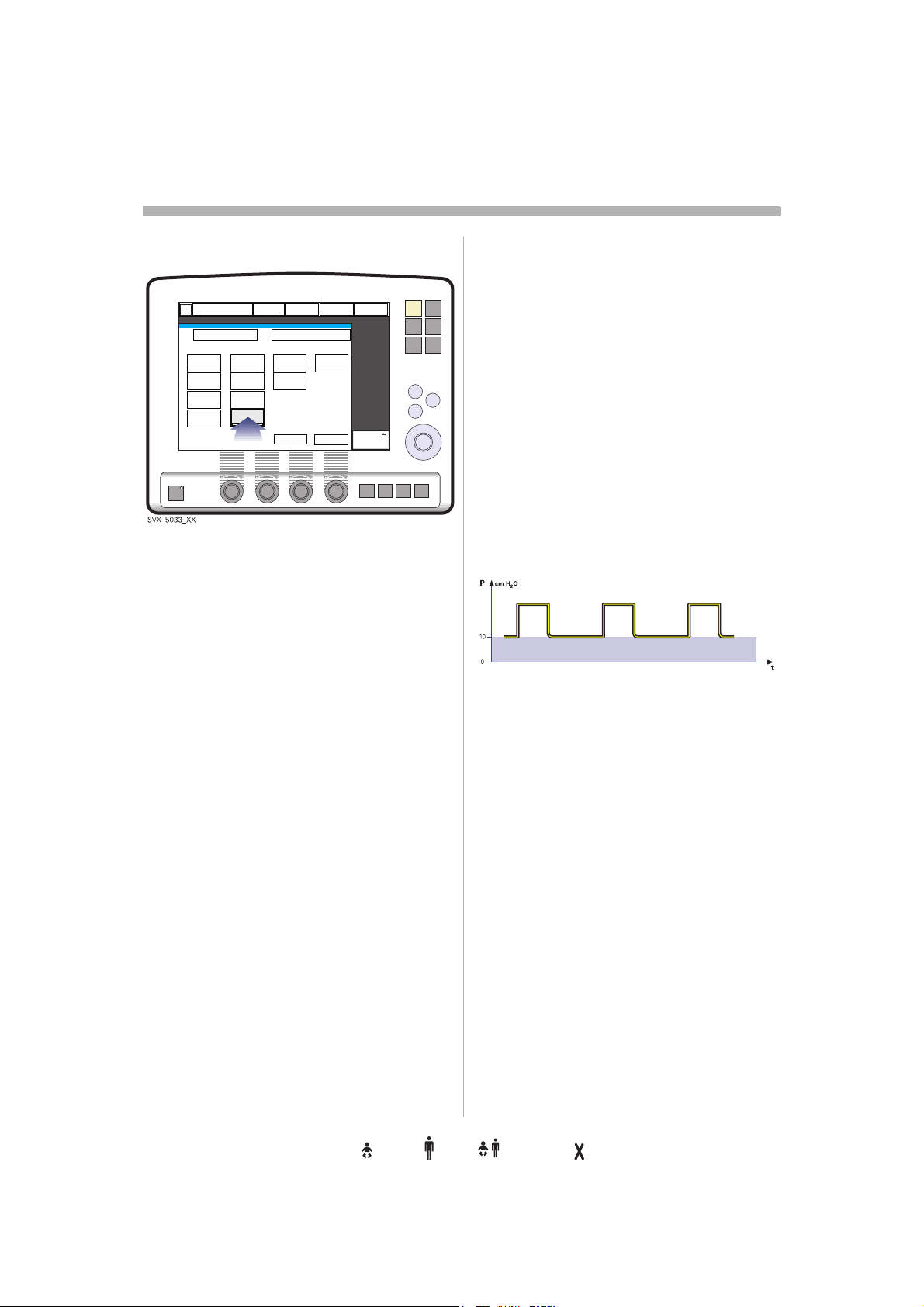
A continuous positive pressure is maintained
in the airways. Properly set this may prevent
collapse of airways. Inspiration starts upon
patient effort. Expiration starts as for
Pressure Support above. Always set the
Apnea time appropriate to the individual
patient situation. If the apnea alarm limit is
reached the ventilator will automatically
switch back to a Back-up mode.
The alarm should alert staff to take action,
either to go back to supported mode or
change to a controlled mode of ventilation.
It is also very important to set lower and
upper alarm limit for expired Minute Volume
The maximum time for inspiration is:
• Infant 1.5 seconds
• Adult 2.5 seconds.
46
Servo… User´s manual
US edition
Infant Adult Universal Option
Order No: 66 00 261
Page 49

Spontaneous breathing/CPAP
in detail
– True spontaneous breathing will occur:
a. In Volume Support when the target
volume is maintained without support
(automatically regulated by the
ventilator)
b. In Pressure Support when the
inspiratory pressure level is set to zero
c. In Automode when either of the above
defined conditions is met.
– Inspiration starts upon patient effort.
Expiration starts:
a. When the inspiratory flow decreases
below a preset fraction of the
inspiratory peak flow (Inspiratory
cycle-off)
b. If the upper pressure limit is
exceeded.
Spontaneous/CPAP
2
Servo… User´s manual
US edition
Order No: 66 00 261
Infant Adult Universal Options
47
Page 50

s
Automode
2
Automode
Functional description
SVX-602_EN
Automode is a ventilator functionality where
the ventilator adapts to the patient's varying
breathing capacity and automatically shifts
between a control mode and a support mode
using a fixed combination of ventilation
modes. There are three different
combinations, depending on the modes
installed:
• Volume Control<----> Volume Support
• PRVC <----> Volume Support
• Pressure Control <----> Pressure Support.
Note: Automode is not possible in NIV.
48
Servo… User´s manual
US edition
Infant Adult Universal Option
Order No: 66 00 261
Page 51

Automode
2
Volume Control<->Volume Support
The ventilator uses the plateau pressure in
the Volume Controlled breath as a reference
pressure for the first Volume Supported
breath.
PRVC <-> Volume Support
Pressure Control<->Pressure
Support
In this combination of Automode - Pressure
Control and Pressure Support - the Direct
Access Knob will regulate the PC above
PEEP (Pressure Control level).
The first supported breath delivered to the
patient has the same pressure level as the
preceding PRVC breath.
Servo… User´s manual
US edition
Order No: 66 00 261
Infant Adult Universal Options
49
Page 52

s
Automode
2
Automode in detail
1. The ventilator starts in control mode and
operates according to the Volume
Control, PRVC or Pressure Control
mode. If the patient triggers a breath, the
ventilator will turn to support mode, to
encourage the patient's respiratory
drive.
2. If the patient is breathing adequately:
a. In Volume Support the ventilator
adjusts the inspiratory pressure level
breath-by-breath to assure the preset
target volume.
b. In Pressure Support the ventilator
assures that the preset inspiratory
pressure level is maintained
constantly during the entire
inspiration.
3. Exceeding the default or manually set
trigger timeout limit without a sufficient
patient effort will cause:
a. In Volume Support; a PRVC or Volume
controlled breath will be delivered
according to the selected automode
functionality.
b. In Pressure Support; a Pressure
controlled breath will be delivered.
4. The ventilator initially adapts with a
dynamic trigger timeout limit. This means
that for the spontaneously triggering
patient, the trigger timeout limit increases
successively until the set trigger timeout
limit is reached.
50
Servo… User´s manual
US edition
Infant Adult Universal Option
Order No: 66 00 261
Page 53

PRVC - Volume Support
1
SVX-165_EN
2a
3a
Volume Control - Volume Support
Automode
4
2
1
SVX-222_EN
2a
3a
Pressure Control - Pressure Support
1
SVX-167_EN
3b2b
4
4
Servo… User´s manual
US edition
Order No: 66 00 261
Infant Adult Universal Options
51
Page 54

s
SIMV
2
Functional description SIMV
SIMV is a combination mode where the
patient receives mandatory breaths
synchronized with his breathing efforts and
according to the selected SIMV mode. The
patient can breath spontaneously with
Pressure Support in between the mandatory
breaths.
There are three different SIMV modes,
depending on the modes installed:
• SIMV (PRVC) + Pressure Support
• SIMV (Volume Control) + Pressure Support
• SIMV (Pressure Control) + Pressure
Support
The mandatory breath
SIMV
(PRVC)+P
S
1
X
2
X
SIMV
(PC) + PS
X
2
X
PC above
PEEP
Tidal volume /
Minute volume
SIMV rate
Breath cycle
time
SIMV
(VC)+ PS
XX
1
X
2
X
The Breath cycle time is the length of the
mandatory breath in seconds.
For example: A SIMV rate of 6, a breath cycle
time of 3 seconds with an I:E ratio of 1:2
means that the inspiration will take 1 second
and the expiration 2 seconds.
SIMV Cycle
10 sec
373
SIMV Period
SVX-9010_EN
Spon. Period
SIMV Period
During the SIMV period, the first triggered
breath will be a mandatory breath. If the
patient has not triggered a breath within the
first 90% of the Breath Cycle time a
mandatory breath will be delivered.
Note: If the ventilator is configured for setting
of Inspiration time, an I:E ratio of 1:2 will be
used to estimate the Breath cycle time.
The spontaneous/pressure supported
breaths are defined by setting the Pressure
support level above PEEP.
I:E ratio /
Inspiration
time
Insp. rise time
Pause time
1
Only when the ventilator is configured for
XXX
XXX
2
X
Minute volume setting.
2
Only when the ventilator is configured for
I:E ratio setting.
The Mandatory breath is defined by the basic
settings (as shown in the table above):
Minute Volume/Tidal Volume (depending on
configuration), PC above PEEP, I:E ratio/
Inspiration time (depending on
configuration), Pause time, Inspiratory rise
time and Breath cycle time.
Note: In the Minute Volume configuration the
Tidal Volume is determined by Minute
Volume divided by SIMV rate.
52
Infant Adult Universal Option
Servo… User´s manual
US edition
Order No: 66 00 261
Page 55

SIMV (PRVC) + Pressure
Support
The following parameters are set:
1. Tidal Volume (ml)/Minute Volume (l/min)
2. SIMV rate (b/min)
SIMV
2
3. PEEP (cmH
4. Oxygen concentration (%)
5. I:E ratio / Insp. time
6. Inspiratory rise time (%/s)
7. Breath cycle time (s)
Note: The soft key Breath cycle time is
not shown when an SIMV mode is
selected and inspiration time is
configured. Refer to page 27.
8. Trigg. Flow / Trigg. Pressure
9. Inspiratory Cycle-off (%)
10. PS (Pressure Support level) above PEEP
(cmH
2
O)
O)
2
Servo… User´s manual
US edition
Order No: 66 00 261
Infant Adult Universal Options
53
Page 56

s
SIMV
2
SIMV (PRVC) + Pressure Support
P
SIMV
Breath cycle
3
time
Spont. period
4
SIMV
Breath cycle
time
2
V
SVX-9027_EN
1
SIMV - in detail
1. This combined control and pressure
support/spontaneous function allows for
preset mandatory breaths synchronized
with the patient's breathing.
2. If there is no trigger attempt within a time
window equal to 90% of the set Breath
cycle time, a mandatory breath is
delivered. (The Breath cycle time is the
total time for one mandatory breath.)
3. The mandatory breath is defined by the
basic settings (mode of ventilation,
breath cycle time, respiratory pattern
and volumes/pressures).
4. The spontaneous/pressure supported
breaths are defined by the setting for
Pressure Support.
90%
time
time
54
Servo… User´s manual
US edition
Infant Adult Universal Option
Order No: 66 00 261
Page 57

SIMV (Volume Control) +
Pressure Support
The following parameters are set:
1. Tidal Volume (ml)/Minute Volume (l/min)
2. SIMV rate (b/min)
SIMV
2
3. PEEP (cmH
4. Oxygen concentration (%)
5. I:E ratio / Insp. time
6. Pause time (%/s)
7. Inspiratory rise time (%/s)
8. Breath cycle time (s)
Note: The soft key Breath cycle time is
not shown when an SIMV mode is
selected and inspiration time is
configured. Refer to page 27.
9. Trigg. Flow / Trigg. Pressure
10. Inspiratory Cycle-off (%)
11. PS (Pressure support) above PEEP
(cmH
2
O)
O)
2
Servo… User´s manual
US edition
Order No: 66 00 261
Infant Adult Universal Options
55
Page 58

s
SIMV
2
SIMV (Volume Control) + Pressure Support
P
SIMV
Breath cycle time Spont. period
3
4
SIMV
Breath cycle time
2
V
SVX-9011_EN
1
SIMV - in detail
1. This combined control and pressure
support/spontaneous function allows for
preset mandatory breaths synchronized
with the patient's breathing.
2. If there is no trigger attempt within a time
window equal to 90% of the set Breath
cycle time, a mandatory breath is
delivered. (The Breath cycle time is the
total time for one mandatory breath.)
3. The mandatory breath is defined by the
basic settings (mode of ventilation,
breath cycle time, respiratory pattern
and volumes/pressures).
4. The spontaneous/pressure supported
breaths are defined by the setting for
Pressure Support.
90%
time
time
56
Servo… User´s manual
US edition
Infant Adult Universal Option
Order No: 66 00 261
Page 59

SIMV (Pressure Control) +
Pressure Support
The following parameters are set:
1. PC (Pressure Control level) above PEEP
(cmH
O)
2
2. SIMV rate (b/min)
SIMV
2
3. PEEP (cmH2O)
4. Oxygen concentration (%)
5. I:E ratio / Insp. time
6. Inspiratory rise time (%/s)
7. Breath cycle time (s)
Note: The soft key Breath cycle time is
not shown when an SIMV mode is
selected and inspiration time is
configured. Refer to page 27.
8. Trigg. Flow / Trigg. Pressure
9. Inspiratory Cycle-off (%)
10. PS (Pressure Support level) above PEEP
(cmH
O)
2
Servo… User´s manual
US edition
Order No: 66 00 261
Infant Adult Universal Options
57
Page 60

s
SIMV
2
SIMV (Pressure Control) + Pressure Support
P
SIMV
Breath cycle
3
time
Spont. period
4
SIMV
Breath cycle
2
time
V
SVX-9027_EN
1
SIMV - in detail
1. This combined control and pressure
support/spontaneous function allows for
preset mandatory breaths synchronized
with the patient's breathing.
2. If there is no trigger attempt within a time
window equal to 90% of the set Breath
cycle time, a mandatory breath is
delivered. (The Breath cycle time is the
total time for one mandatory breath.)
3. The mandatory breath is defined by the
basic settings (mode of ventilation,
breath cycle time, respiratory pattern
and volumes/pressures).
4. The spontaneous/pressure supported
breaths are defined by the setting for
Pressure Support.
90%
time
time
58
Servo… User´s manual
US edition
Infant Adult Universal Option
Order No: 66 00 261
Page 61

Bi-Vent
Functional description
Bi-Vent
2
Bi-Vent is pressure controlled breathing that
allows the patient the opportunity of
unrestricted spontaneous breathing. Two
pressure levels are set together with the
individually set duration of each level.
Spontaneous breathing efforts can be.
assisted by pressure support
The following parameters are set:
1. Pressure high (P
pressure level (cmH
) for the higher
High
O)
2
2. PEEP for the lower pressure level
O)
(cmH
2
3. Oxygen concentration (%)
4. Time at the higher pressure (T
High
) level
(s)
5. Time at the lower pressure (T
PEEP
) level
(s)
6. Inspiratory rise time (s)
7. Trigg. Flow / Trigg. Pressure
8. Inspiratory Cycle-off (%)
9. Pressure Support level above P
O)
(cmH
2
High
In the Bi-Vent mode the ventilator uses two
shifting pressure levels, with the patient
being able to breath spontaneously on both
these levels.
Since Bi-Vent is basically a controlled mode
of ventilation, apnea alarm and back-up
ventilation are not available. It is also very
important to set lower and upper alarm limit
for expired Minute Volume.
Every Bi-Vent cycle is regarded as
autonomous and therefore most of the
measured values are updated every Bi-Vent
cycle, i.e. minute volumes, respiratory rate,
mean pressure and end expiratory pressure.
In accordance to this, associated alarms are
also handled for every Bi-Vent cycle.
At extreme settings the update of measured
values and alarms will show a mandatory
frequency dependence even in the face of
preserved spontaneous breathing.
As a result of switching between two
different pressure levels, the tidal volumes
may vary significantly between different
breaths. This may also be the case for etCO
concentration.
It is not recommended to use Auto scale in
Bi-Vent mode, when patient is breathing
spontaneous on both levels.
2
10. Pressure Support level above PEEP
O)
(cmH
2
Servo… User´s manual
US edition
Order No: 66 00 261
Infant Adult Universal Options
59
Page 62

s
Bi-Vent
2
Bi-Vent in detail
1
1
5
3
3
SVX-184_XX
This function allows for spontaneous
breathing / pressure supported ventilation at
two different pressure levels. These basic
levels are individually set, as well as the time
in seconds at each level.The ventilator
always tries to synchronize with the patient´s
breathing.
1. Bi-Vent cycle; T
High
+ T
PEEP
2. PEEP
3. P
High
4. The pressure support level is set
individually: PS above PEEP
5. PS above P
High
2
2
4
60
Servo… User´s manual
US edition
Infant Adult Universal Option
Order No: 66 00 261
Page 63

Non Invasive Ventilation (NIV)
2
Non Invasive Ventilation
This chapter refers to when the Servo-i is
used during Non Invasive Ventilation (NIV).
NIV refers to ventilation, where the patient is
not intubated or tracheotomized. It is
achieved using a nasal mask / prongs, face
mask / prongs or full-face mask / prongs.
Note: In NIV, flow and pressure curves and
the measured values: VTi, VTe, MVe, MVi are
compensated for leakage.
WARNINGS!
• Avoid high inspiratory pressure as it may
lead to gastric overdistension and risk of
aspiration. It may also cause excessive
leakage.
• The dead space will increase when use of
a mask / prongs.
• NIV is not intended to be used on
intubated patients.
•CO
measurement will be affected by
2
mask / prongs leakage.
Cautions:
Read more about NIV
Intended population page 4
Ventilation modes (NIV): pages 62, 63
Alarm settings: page 73
Preparation: page 160
• Mask / prongs leakage might affect the
nebulizer efficiency.
• It is not recommended to use the nebulizer
during NIV as the nebulized drug might
come in contact with the patient eyes in
case of leakage.
Important:
• The mask / prongs must be applied in
order to avoid leakage.
• Selection of the mask / prongs must take
into consideration proper size and an
accurate adaptation to the patient.
•CO
rebreathing will increase during NIV
2
and use of a face mask / prongs.
Servo… User´s manual
US edition
Order No: 66 00 261
Infant Adult Universal Options
61
Page 64
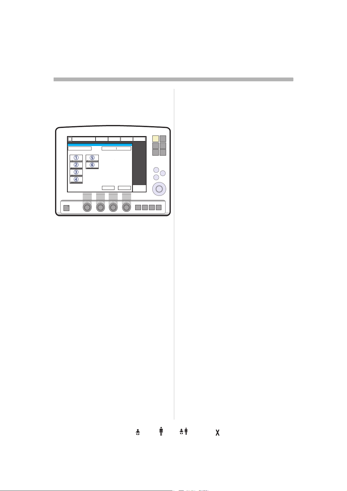
s
NIV - Pressure Control
2
Functional description
Pressure Control
The Pressure Controlled (NIV) mode is a
controlled breathing mode.
SVX-9013_XX
The following parameters are set:
1. PC (Pressure Control level) above PEEP
(cmH
O)
2
2. Respiratory Rate (b/min)
3. PEEP (cmH
4. Oxygen concentration (%)
O)
2
Differences from invasive Pressure
control mode:
• When the Standby key is pressed a
waiting position dialog is shown. All
patient related alarms are turned off during
120 seconds. Press the Start ventilation
pad to start the ventilation.
• During NIV the ventilator automatically
adapts to the variation of leakage in order
to maintain the required pressure and
PEEP level. If the leakage is excessive, the
ventilator will issue a high priority alarm,
deliver a continuous flow and pause
breath cycling. Ventilation will resume
automatically if the leakage decreases.
Ventilation can also be started manually by
pressing the Start ventilation pad in the
excessive leakage dialog.
• Trigger sensitivity cannot be set in NIV.
Read more about NIV
Intended population page 4
NIV general information: page 61
Ventilation modes (NIV): page 63
Alarm settings: page 73
Preparation: page 160
5. I:E ratio / Insp. time
6. Inspiratory rise time (%/s)
62
Infant Adult Universal Option
Servo… User´s manual
US edition
Order No: 66 00 261
Page 65

NIV - Pressure Support
2
Functional description
Pressure Support
Pressure Support (NIV) is a patient initiated
breathing mode in which the ventilator
supports the patient with a set constant
pressure.
SVX-9014_XX
The following parameters are set:
1. PS (Pressure Support level) above PEEP
(cmH
O)
2
2. PEEP (cmH
3. Oxygen concentration (%)
4. Inspiratory rise time (s)
5. Inspiratory Cycle-off (%)
6. NIV rate (b/min)
7. Backup Ti (s)
O)
2
Differences from invasive Pressure
support mode:
• When the Standby key is pressed a
waiting position dialog is shown. All
patient related alarms are turned off during
120 seconds. Press the Start ventilation
pad to start the ventilation.
• During NIV the ventilator automatically
adapts to the variation of leakage in order
to maintain the required pressure and
PEEP level. If the leakage is excessive, the
ventilator will issue a high priority alarm,
deliver a continuous flow and pause
breath cycling. Ventilation will resume
automatically if the leakage decreases.
Ventilation can also be started manually by
pressing the Start ventilation pad in the
excessive leakage dialog.
• During Pressure support the system
ensures a minimum Back-up Rate and
maintains the set Inspiratory pressure and
PEEP level. The Back-up Rate is activated
when the spontaneous breathing rate is
lower then the Back-up Rate, but the
ventilator does not activate a Backup
ventilation mode as in Invasive Pressure
Support.
• Trigger sensitivity cannot be set in NIV.
Read more about NIV
Intended population page 4
NIV general information: page 61
Ventilation modes (NIV): page 62
Alarm settings: page 73
Preparation: page 160
Servo… User´s manual
US edition
Order No: 66 00 261
Infant Adult Universal Options
63
Page 66
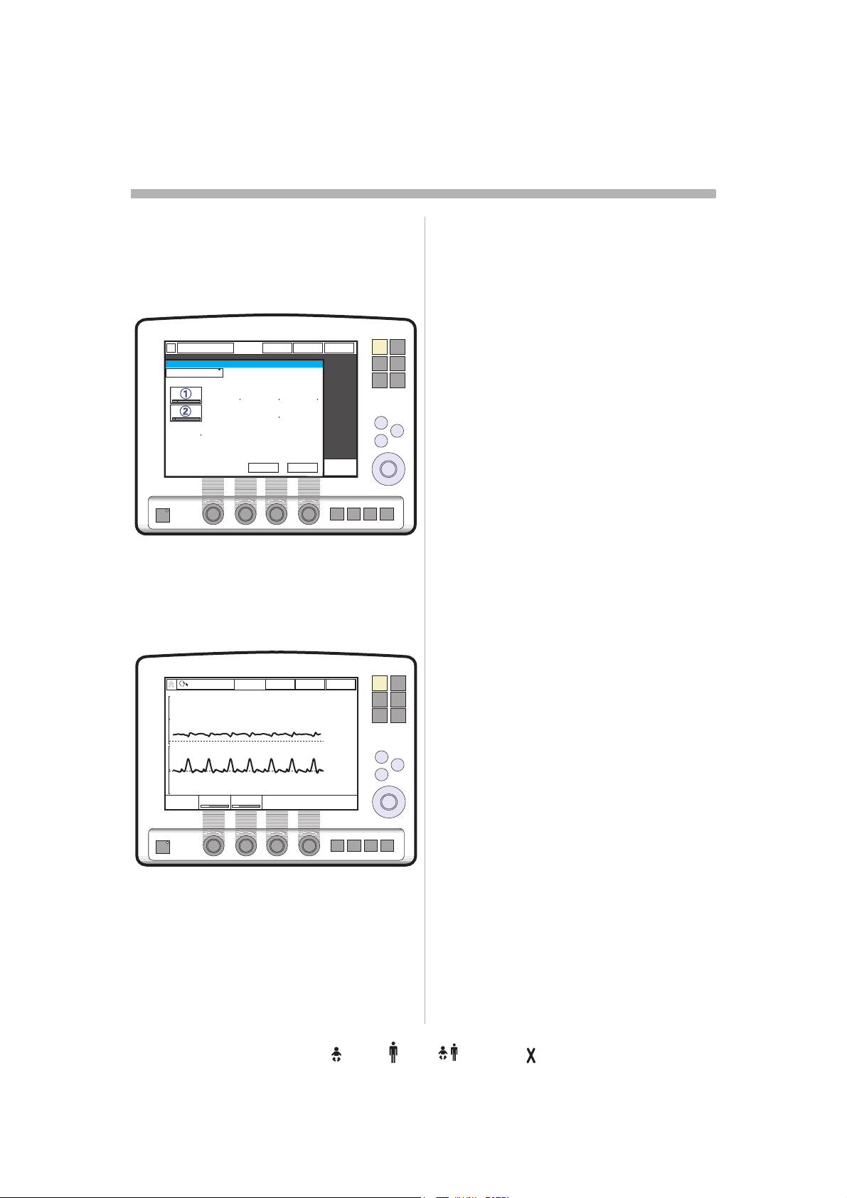
s
NIV - Nasal CPAP
2
Functional description Nasal
CPAP
The mode Nasal Continuous Positive Airway
Pressure is used when the patient is
breathing spontaneously.
SVX-9057
The following parameters are set:
1. CPAP (cmH
2. Oxygen concentration (%)
O)
2
Differences from invasive CPAP
• When the Standby key is pressed a
waiting position dialog is shown. All
patient related alarms are turned off during
120 seconds. Press the Start ventilation
pad to start the ventilation.
• Trigger and cycle-off is automatically
adapted to the leakage and cannot be set
in Nasal CPAP.
• There is no backup ventilation available in
Nasal CPAP.
• The apnea alarm can be turned off in
Nasal CPAP
The following functions are not available
during Nasal CPAP ventilation:
•Volume curve
• Loops
• Open Lung Tool
• Additional values
• Additional settings
• Inspiratory hold
• Expiratory hold
•CO
Analyzer.
2
SVX-9061
64
WARNING! Patient effort and artifacts
affecting patient flow or pressure such as
heart beats, movement of patient tubings,
intermittent leakage may not always be
correctly detected or discriminated. This may
affect the accuracy of alarms and measured
parameters, therefore, we advise that a
ventilator-independent means of monitoring
the patient should be in place.
Read more about NIV
Intended population page 4
NIV general information: page 61
Ventilation modes (NIV): page 62
Alarm settings: page 73
Preparation: page 160
Infant Adult Universal Option
Servo… User´s manual
US edition
Order No: 66 00 261
Page 67

Open Lung Tool
Clinical performance
The Open Lung Tool is a tool for graphically
visualizing measured and calculated values
for easier interpretation of already available
ventilation data. Three simultaneous
graphical trends are presented with a fixed
set of parameters as a function of a number
of collected breaths. The User Interface
features an adjustable cursor which helps
illustrate the opening and closing airway
pressures. This alternative presentation may
be used for immediate visualization of the
effect of altered settings.
Note: When the Y Sensor Measuring
function is active, then the values recorded in
the Open Lung Tool are based on values
measured at the Y-piece. Note that when this
function is disabled or enabled, then the
compliance in the patient circuit may cause
the values in the Open Lung Tool to change.
Read more about the Open
Lung Tool
Operating: page 175
Servo… User´s manual
US edition
Order No: 66 00 261
Infant Adult Universal Options
Open Lung Tool
SVX-9023_XX
The following parameters are presented:
– In the top window, measured End
Inspiratory Pressure (EIP) and Positive
End Expiratory Pressure (PEEP) are
simultaneously presented, breath-bybreath.
– In the middle window, measured
Inspiratory tidal volume (VTi) and
Expiratory tidal volume (VTe) are
simultaneously presented, breath-bybreath.
– Dynamic compliance (C dyn i) is
calculated breath-by-breath and filtered
before presentation. (C dyn i = VTi / EIP –
PEEP)
– In the lower window measured Tidal CO
elimination (VTCO
presented as well, breath-by-breath
(CO
– The time parameter on the lower right
screen indicates how long it will take at
the current settings for the waveform to
fill the axis. Changing the scaling with
the zoom in or out function will change
the time and number of breaths needed
for filling the axis.
– The breaths parameter on the lower right
screen indicates the number of breaths
at the current respiratory rate it will take
for the waveform to fill the axis.
Analyzer).
2
) is simultaneously
2
2
65
2
Page 68

s
Ventilatory parameters, overview
2
SVX-202_EN
When a ventilation mode is selected, the only
parameters shown are those affecting the
actual mode. Below are all the mode-related
parameters presented.
1. Respiratory rate (RR) Rate of controlled
mandatory breaths or used for calculation of
target volume (b/min).
2. Tidal volume (VT) Volume per breath or
target volume (ml).
Minute volume (Vmin) Volume per minute or
target Minute volume (ml/min or l/min).
Presentation can be configured to either tidal
or minute volume.
3. PC above PEEP Inspiratory pressure level
for each breath (cmH
O) in Pressure Control.
2
4. PS above PEEP Inspiratory pressure
support level for triggered breaths (cmH
in Pressure Support.
O)
2
5. Inspiratory rise time (T inspiratory rise)
Time to full inspiratory flow or pressure at the
start of each breath, as a percentage of the
breath cycle time (%), or in seconds (s).
9. Trigger sensitivity
a) Below zero: Trigger sensitivity is pressure
dependant. The pressure below PEEP which
the patient must create to initiate an
inspiration (cmH
O) is indicated.
2
b) Above zero: Trigger sensitivity is flow
dependent. As the dial is advanced to the
right (step wise from the green into the red
area) the trigger sensitivity increases i.e the
inhaled fraction of the bias flow leading to
triggering is reduced.
10. PEEP Positive End Expiratory Pressure
(cmH
O).
2
11. Inspiratory cycle-off Fraction of
maximum flow at which inspiration should
switch to expiration (%).
6. I:E ratio (I:E) (Inspiration time + Pause
time): Expiration time.
7. Inspiration time (T
pressure delivery to the patient (s).
8. Pause time (T
pressure delivery (% or s).
) Time for active flow or
i
) Time for no flow or
pause
66
Infant Adult Universal Option
Servo… User´s manual
US edition
Order No: 66 00 261
Page 69

Ventilatory parameters, overview
SVX-218_EN
SVX-203_EN
12. Breath cycle time (Breath cycle T) Total
cycle time per mandatory breath in SIMV
(inspiratory + pause + expiratory). Set in
seconds.
2
13. SIMV rate Rate of controlled mandatory
breaths (b/min).
14. Trigger timeout The maximum allowed
apnea time in Automode, after which the
system switches to controlled ventilation (s).
– O
concentration (O2 Conc.) O2
2
concentration in inspiratory gas (not
shown in the figure).
Servo… User´s manual
US edition
Order No: 66 00 261
Infant Adult Universal Options
67
Page 70

s
Ventilatory parameters, overview
2
SVX-204_XX
15. Time high (T
Bi-Vent (s).
16. Time PEEP (T
Bi-Vent (s).
) Time at P
High
) Time at PEEP level in
PEEP
High
level in
17. Pressure Support above Pressure high
(PS above P
support level for breaths triggered during the
T
period in Bi-Vent (cmH2O).
High
) Inspiratory pressure
High
18. Pressure Support above PEEP
(PS above PEEP) Inspiratory pressure
support level for breaths triggered during the
T
period in Bi-Vent (cmH2O).
PEEP
(P
19. Pressure high
Expiratory Pressure at the upper level in BiVent (cmH
2
O).
) Positive End
High
20. PEEP Positive End Expiratory Pressure
at the lower level in Bi-Vent (cmH
2
O).
68
Servo… User´s manual
US edition
Infant Adult Universal Option
Order No: 66 00 261
Page 71

Notes
2
..................................................................
..................................................................
..................................................................
..................................................................
..................................................................
..................................................................
..................................................................
..................................................................
..................................................................
..................................................................
..................................................................
..................................................................
..................................................................
..................................................................
..................................................................
..................................................................
..................................................................
..................................................................
..................................................................
..................................................................
..................................................................
..................................................................
..................................................................
..................................................................
Servo… User´s manual
US edition
Order No: 66 00 261
Infant Adult Universal Options
..................................................................
..................................................................
..................................................................
..................................................................
..................................................................
..................................................................
69
Page 72

2
s
Notes
..................................................................
..................................................................
..................................................................
..................................................................
..................................................................
..................................................................
..................................................................
..................................................................
..................................................................
..................................................................
..................................................................
..................................................................
..................................................................
..................................................................
..................................................................
..................................................................
..................................................................
..................................................................
..................................................................
..................................................................
..................................................................
..................................................................
..................................................................
..................................................................
70
Infant Adult Universal Option
..................................................................
..................................................................
..................................................................
..................................................................
..................................................................
..................................................................
Servo… User´s manual
US edition
Order No: 66 00 261
Page 73

3. Patient safety
Contents
Alarms- General . . . . . . . . . . . . . . . . . . . . . . . . . 72
High priority alarms . . . . . . . . . . . . . . . . . . . . . . . 72
Medium priority alarms . . . . . . . . . . . . . . . . . . . . 72
Low priority alarms. . . . . . . . . . . . . . . . . . . . . . . . 72
Technical alarms. . . . . . . . . . . . . . . . . . . . . . . . . . 72
Alarm output connection option. . . . . . . . . . . . 72
The alarm profile window . . . . . . . . . . . . . . . . . 73
The alarm window . . . . . . . . . . . . . . . . . . . . . . . 74
Alarms - Visual / audible . . . . . . . . . . . . . . . . . . 75
Audio off (Silence / Pre-silence of alarm) . . . . 76
General. . . . . . . . . . . . . . . . . . . . . . . . . . . . . . . . . 76
Audio off of non-latching alarms . . . . . . . . . . . . . 76
Built-in safety precautions . . . . . . . . . . . . . . . . 78
Servo… User´s manual
US edition
Order No: 66 00 261
Infant Adult Universal Options
71
Page 74

s
Alarms- General
3
Several measures have been taken to design
this system for safe treatment and use.
The alarms are based on three priority levels;
High, Medium and Low.
High priority alarms
These alarms are warnings and are indicated
by a red background. They are latched, i.e.
the visual indication remains even though the
alarm condition ceases.The background
color switches to yellow if the alarm
condition returns to normal. Latched alarms
require manual resetting.
Note: NIV alarm Leakage out of range is not
latched.
For more information about the high
priority alarms see page 226.
Medium priority alarms
These alarms are advisory. They may be
reset (cleared) even though the alarm
condition remains.
For more information about the medium
priority alarms see page 231.
Low priority alarms
These alarms are cautionary and are
indicated by a yellow background.
For more information about the low
priority alarms see page 234.
Alarm output connection
option
An Alarm output connection option makes it
possible to connect the ventilator to an
external alarm signal system. High and
medium priority alarms are transferred. The
alarm output signal is active as long as the
audio alarm is active on the ventilator.
Importants:
• It is required that the patient is never left
unattended and that external alarm is used
only to draw extra attention to a patient.
• The alarm output is a non-guaranteed
alarm according to IEC 60601-1-8 and it is
recommended that the user establish a
pre-use check routine for this application.
Technical alarms
Technical problem identified by a code.
For more information about the high
priority alarms see page 239.
Alarm signals
All alarms are visual and audible.
WARNINGS!
• To protect the patient against high airway
pressures, the Upper pressure limit must
always be set to the relevant value so as to
provide adequate patient safety.
• To provide adequate patient safety, always
set the alarm limits at relevant values.
72
Infant Adult Universal Option
Servo… User´s manual
US edition
Order No: 66 00 261
Page 75

The alarm profile window
3
Alarm profile window
1. Press the Alarm profile key
Shows all applicable alarms and settings for
both lower and upper limits. Also used for
adjusting current limits and alarm sound
level.
Note: Current alarm limits are displayed
adjacent to the measured value, in smaller
figures to the right of the display. Default
values are displayed during power up and
when admitting a new patient. Always make
sure that values are appropriate for the
patient.
Non Invasive Ventilation
SVX-9016_XX
1. Press the Alarm profile key to show the
applicable alarms for Non Invasive
Ventilation (NIV).
2. The bell indicates if the alarm is audible
active or Audio off (permanently
silenced, a crossed bell).
The apnea alarm can be turned off in Nasal
CPAP.
3. To turn off the apnea alarm in Nasal
CPAP continue turning control wheel
after maximum time limit has been
reached.
Servo… User´s manual
US edition
Order No: 66 00 261
When the apnea alarm is turned off, a
message is displayed in the message
area.
Read more about NIV
Ventilation modes page 61
Preparation page 160
Infant Adult Universal Options
73
Page 76

s
The alarm window
3
Current alarms window
This window can be displayed if more than
one alarm is active.
1. Press the bell (s) in the alarm message
pad.
2. All alarms are shown in a window. This is
dynamic and will be updated if more
alarms occur while the window is open.
The alarms are listed by priority and 10
alarm messages are displayed at the
most.
3. Press the History pad.
4. The last 16 alarm-dependent events are
listed chronologically. The most recent
event is at the bottom.
Note: For viewing more than the latest 10
alarms, use the Event log to view all logged
alarms (refer to page 270).
74
Infant Adult Universal Option
Servo… User´s manual
US edition
Order No: 66 00 261
Page 77

Alarms - Visual / audible
3
Visual
1. A text message explaining the cause of
the alarm flashes in the alarm message
area. The alarm with highest priority is
displayed first.
2. The corresponding measured value or
set value box flashes and an arrow
points at the exceeded limit.
A red background color indicates a high
priority alarm. A yellow background indicates
a medium or low priority alarm.
A high priority alarm which has been active
but for which the condition has returned to
normal is latched and requires manual
resetting. (Latched alarms: The alarm text
remains even though the alarm condition
ceases.)
Note: NIV alarm Leakage out of range is not
latched.
Audible
An active alarm is indicated by a distinct, but
soft alarm signal. The sound level can be
adjusted, e.g. lowered during the night time.
(Set sound level is indicated in the Alarm
profile window.)
Technical errors may also be indicated by a
signal similar to that a medium priority alarm,
generated by a sounding device in the
Patient Unit.
Two bells in the alarm message area indicate
that more than one alarm is activated.
Servo… User´s manual
US edition
Order No: 66 00 261
Infant Adult Universal Options
75
Page 78

s
Audio off (Silence / Pre-silence of alarm)
3
General
All alarms except for No battery capacity and
technical error alarms can be silenced (Audio
pause) for two minutes. New alarms can be
activated during this period. In Standby, only
the following alarms are applicable:
– No battery capacity (when Battery
module is connected)
– Limited battery capacity (when Battery
module is connected)
– Battery operation (when Battery module
is connected)
– Technical error
– Touch screen or knob press time
exceeded
– Internal temperature: High
– Exp. cassette exchanged
– Technical error in Expiratory cassette
Audio off (Silence of alarms)
At any time while the ventilator is operating
(either Invasive or Non Invasive Ventilation
modes), alarms can be placed into a state of
audio off (silence alarms).
Non Invasive Ventilation
When Non Invasive Ventilation is chosen, the
following alarms can be placed into a state of
audio off (silenced alarms):
– Minute volume
– Respiratory rate
– PEEP
– End tidal CO
– CPAP ( Nasal CPAP)
By pressing the corresponding bell symbol in
the alarm profile window the button changes
to a crossed bell to indicate Audio Off. It is
also possible to configure these alarms
individually to be set to the Audio Off state by
default.
Note: When an alarm is silenced (Audio off)
in the NIV mode, a symbol will appear on the
screen, next to the corresponding measured
value, saying Audio Off (a bell with negation
cross). The Audio Off symbol will remain on
the screen until the user reactivates the
alarms or returns to the standby mode. If the
user then enters Invasive ventilation and after
that returns to NIV, the audible alarms will be
reset to their default states.
(CO2 Analyzer)
2
Audio off of non-latching
alarms
For a very limited number of alarms a single
alarm condition can be silenced (Audio off)
during the remaining time of the continuing
alarm condition when the message Audio
off? is shown. These alarms, such as Battery
operation and Low Air/O
will be re-activated the next time the alarm
condition occurs.
supply pressure,
2
76
Servo… User´s manual
Infant Adult Universal Option
US edition
Order No: 66 00 261
Page 79

Audio pause (Silence / Pre-silence alarm)
3
Audio pause/Prolong pre-silence
period/Clear latched alarm
SVX-5098_EN
1. Press the Audio pause (Silence/Presilence alarm) key briefly, for less than
two seconds:
• Active alarms are silenced (Audio
pause) for 2 minutes.
• If already silenced, the silent period is
prolonged for two minutes.
• Latched alarms disappear (latched
alarms: the alarm text remains even
though the alarm condition ceases).
An alarm silence (Audio pause) symbol and
the remaining time are then displayed in the
message area.
Pre-silence alarm (Audio pause))
SVX-5099_EN
1. If you press the Audio pause (Silence/
Pre-silence alarm) key for more than two
seconds:
•The active alarms are silenced (Audio
pause), i.e. a two minute period is
started.
•All other alarms are silenced (Audio
pause) for 2 minutes, except those
which cannot be silenced.
–Latched alarms disappear from the
alarm message area.
Servo… User´s manual
US edition
Order No: 66 00 261
Infant Adult Universal Options
77
Page 80

s
Built-in safety precautions
3
For patient safety your Servo-i Ventilator
System also has a range of built-in safety
precautions.
Apnea alarm
The apnea alarm is applicable in all
supported/spontaneous modes.
Note: When using the knob to adjust a value,
the defined safety limits may be
unintentionally reached or exceeded. In this
case, the knob will become inoperable for 2
seconds to make you aware that the safety
limit has been passed. (Note that this is only
valid for Servo-i Infant and Servo-i Universal
System versions).
Backup ventilation
In case of exceeded apnea in Volume
Support or Pressure Support, a safety
backup mode is activated with default
breathing frequency and set / default values.
High pressures
The safety valve opens if the pressure in the
inspiratory channel is too high.
Caution: If airway pressure rises 6 cmH
above the set upper pressure limit the safety
valve opens. The safety valve also opens if
system pressure exceeds 117
± 7 cmH
O
2
O.
2
NIV rate
During Pressure support (NIV) the system
ensures a minimum Back-up Rate and
maintains the set Inspiratory pressure and
PEEP level. The Back-up Rate is activated
when the spontaneous breathing rate is
lower then the Back-up Rate.
No gas supply
If the air and O2 pressure is too low the safety
valve and the expiratory valve will open. An
alarm will be activated simultaneously.
Parameters and alarm limits
The system has default values for
parameters and alarm limits. These are valid
until you adjust them before/after connection
to a patient. You can also enter new default
values or use the values previously applied.
Standby position
All settings will be saved when the ventilator
is set in standby position. The ventilator can
thus be prepared and the CO
warmed up for admission in advance.
transducer
2
Gas supply O2/Air
If the O2 or air supply pressure is too low the
flow from the missing gas is automatically
compensated for. The patient will get preset
volumes and pressure with O
alarm will be activated.
/air and an
2
Mains failure and battery
In case of a mains failure, the ventilator will
automatically switch over to battery
operation. The switch is indicated by a
medium priority alarm. The remaining battery
capacity is displayed in the status menu on
top of the screen. In case of a mains failure
and no Battery module has been inserted or
connected, a high priority alarm is activated.
The inspiratory and expiratory valves are
opened to allow for breathing through the
ventilator. All settings are saved until the
ventilator is powered again.
78
Infant Adult Universal Option
Read more about the alarms
Alarm settings: page 165
Troubleshooting: page 225
Auto set values
calculation: page 244
Default values: page 249
Keys and touch pads: pages 268, 269.
Servo… User´s manual
US edition
Order No: 66 00 261
Page 81

Notes
3
..................................................................
..................................................................
..................................................................
..................................................................
..................................................................
..................................................................
..................................................................
..................................................................
..................................................................
..................................................................
..................................................................
..................................................................
..................................................................
..................................................................
..................................................................
..................................................................
..................................................................
..................................................................
..................................................................
..................................................................
..................................................................
..................................................................
..................................................................
..................................................................
Servo… User´s manual
US edition
Order No: 66 00 261
Infant Adult Universal Options
..................................................................
..................................................................
..................................................................
..................................................................
..................................................................
..................................................................
79
Page 82

3
s
Notes
..................................................................
..................................................................
..................................................................
..................................................................
..................................................................
..................................................................
..................................................................
..................................................................
..................................................................
..................................................................
..................................................................
..................................................................
..................................................................
..................................................................
..................................................................
..................................................................
..................................................................
..................................................................
..................................................................
..................................................................
..................................................................
..................................................................
..................................................................
..................................................................
80
Infant Adult Universal Option
..................................................................
..................................................................
..................................................................
..................................................................
..................................................................
..................................................................
Servo… User´s manual
US edition
Order No: 66 00 261
Page 83

4. Device description
Contents
The system . . . . . . . . . . . . . . . . . . . . . . . . . . . . . 82
An overview . . . . . . . . . . . . . . . . . . . . . . . . . . . . . 83
Configuration . . . . . . . . . . . . . . . . . . . . . . . . . . . . 85
Options / Accessories . . . . . . . . . . . . . . . . . . . . . 86
User Interface
User Interface - General. . . . . . . . . . . . . . . . . . . . 87
User Interface - Connections and labels . . . . . . . 88
Touch screen . . . . . . . . . . . . . . . . . . . . . . . . . . . . 90
Main Rotary Dial. . . . . . . . . . . . . . . . . . . . . . . . . . 90
Fixed keys . . . . . . . . . . . . . . . . . . . . . . . . . . . . . . 91
Adjusting parameter values . . . . . . . . . . . . . . . . . 91
Waveforms . . . . . . . . . . . . . . . . . . . . . . . . . . . . . . 92
Measured value boxes . . . . . . . . . . . . . . . . . . . . . 92
Servo… User´s manual
US edition
Order No: 66 00 261
User Interface - Positioning . . . . . . . . . . . . . . . . . 93
User Interface - Accessories . . . . . . . . . . . . . . . . 94
Patient Unit
Patient Unit - Connections and labels . . . . . . . . . 96
Patient Unit - Expiratory cassette . . . . . . . . . . . . 98
Mobile Cart Servo-i . . . . . . . . . . . . . . . . . . . . . . 99
Holders . . . . . . . . . . . . . . . . . . . . . . . . . . . . . . . 100
Servo Ultra Nebulizer. . . . . . . . . . . . . . . . . . . . 102
Analyzer Servo-i . . . . . . . . . . . . . . . . . . . . 104
CO
2
Y Sensor measuring. . . . . . . . . . . . . . . . . . . . . 106
Battery module . . . . . . . . . . . . . . . . . . . . . . . . . 108
Ventilation Record Card. . . . . . . . . . . . . . . . . . 114
Compressor Mini . . . . . . . . . . . . . . . . . . . . . . . 115
System transport and storage . . . . . . . . . . . . 116
Infant Adult Universal Options
81
Page 84

s
The system
4
The ventilator
All ventilatory settings are made on the User
Interface panel. It can either be operated by
the touch screen and the Main Rotary Dial or
by using the Main Rotary Dial only. Flow and
pressure are continuously measured by
transducers and controlled by a feedback
system in the Patient Unit. The information is
compared with the User Interface settings,
and a difference between the actual
measured value and the preset/calculated
values will cause adjusted gas delivery
according to the target flow/volume/
pressure. The Servo-i Ventilator System has
two gas modules, one for air and one for O
Gas can be connected from a medical
pipeline system, a compressor or gas tanks.
Air can also be supplied by a compressor.
2
6
7
.
8
9
82
1. Air and O
2. Mains supply
3. User Interface
4. Patient Unit
5. Expiratory inlet
6. Servo guard, viral/bacterial filter
7. Inspiratory outlet
8. Patient system
9. Module compartment
Infant Adult Universal Option
supply
2
Servo… User´s manual
US edition
Order No: 66 00 261
Page 85

An overview
The system
4
6
1. The ventilator can be delivered in three
configurations. Your configuration is
clearly indicated on the Patient Unit, at
start up and in the Brief Instructions.
The Servo-i Infant with
defaults, scales and safety
precautions, designed for use with Infant
patients. It is standard configurated for
pressure controlled modes of
ventilation.
The Servo-i Adult with defaults,
scales and safety precautions, designed
for use with adolescent and adult
patients. It is standard configurated for
volume controlled modes of ventilation.
The Servo-i Universal (Basic or
Extended edition) is an
advanced ventilator to be used with
infants and adults. Enhanced
functionality i.e. a comprehensive array
of different ventilation modes, extended
Tidal Volume range, allows for advanced
ventilatory treatment in both categories.
2. The User Interface, where all settings are
made and effects are monitored.
3. The Patient Unit, where gases are
administrated, also has slots for Battery
modules and future function modules.
Battery module allow backup during
mains failure and transport.
4. The Servo Ultra Nebulizer is
operated from the User Interface.
Note: The Aeroneb Professional
Nebulizer System can be used as a stand
alone nebulizer system. Refer to
separate manual.
5. The mainstream CO
and calculations are displayed on the
User Interface.
6. Y Sensor measuring. Allows
measurement of pressure and flow right
up to the Y-piece.
measurement
2
Servo… User´s manual
US edition
Order No: 66 00 261
Infant Adult Universal Options
83
Page 86

s
6
The system
4
In the system
Default values give fast system start-up.
User set values tailor the ventilatory
management. Signals are fed to the Patient
Unit, which executes ventilation managed by
the servo control system. The internal design
of the Patient Unit allows for true inspiratory
and expiratory regulation and measurement.
Set, measured and calculated values are
presented on-screen breath-by-breath.
1. Patient data can be transferred to a
Personal Computer via the Ventilation
record card for further processing and
storage.
2. Signals are conveyed from the User
Interface for controlling of drug
nebulization.
Important: Only valid for the built in
Servo Ultra Nebulizer.
3. Data communication to a Personal
Computer is possible via the
Communication Interface Emulator (CIE)
and the serial communication port
(RS 232C).
84
Infant Adult Universal Option
4. An alarm output connection option
makes it possible to connect the
ventilator to an external alarm signal
system
5. Signals from the CO
sensor are conveyed to the User
Interface, where they are calculated and
displayed on the screen.
6. Y Sensor measurements are
conveyed to the User Interface, where
they are calculated and displayed on the
screen.
Capnostat
2
Servo… User´s manual
US edition
Order No: 66 00 261
Page 87

System elements; overview
Configuration
4
Functionality/Configuration
Alarm output connection option
Automode, pressure
Automode, PRVC
Automode, volume
Bi-Vent
CO
Analyzer
2
NIV (Non Invasive Ventilation)
Nasal CPAP
Open Lung Tool
Pressure Control
Pressure Support
PRVC (Pressure Reg. Volume
Control)
SIMV (Press. Contr.) +Pressure
Support
SIMV (PRVC) + Pressure Support
SIMV (Vol. Contr.) + Pressure
Support
Suction Support
Upgrade to universal (all patient
categories)
Volume Control
Volume Support
Y Sensor measuring
Reference in
this manual
Basic Extended
ttt t
ttt %
ttt %
ttt %
ttt t
ttt t
pages 72, 150
page 48
page 48
page 48
page 59
pages 104,
151
ttt t
t - ttpage 64
ttt %
pages 61, 160
pages 65,
175, 176
%t % %
%%% %
ttt %
%t % %
tt% %
t%% %
%%% %
tt
t%% %
ttt %
ttt t
page 38
page 43
page 32
pages 52, 57
pages 52, 53
pages 52, 55
page 170
-
page 35
page 40
pages
106,135, 192,
248
% included (in standard configuration)
t optional
Note: Refer to page 83 for Servo-i
configuration definition.
Servo… User´s manual
US edition
Order No: 66 00 261
Infant Adult Universal Options
85
Page 88

s
Options / Accessories
4
General options / accessories Reference in this manual
Aeroneb Professional Nebulizer System Refer to separate manual
Battery module Servo-i page 108
CO
Analyzer Servo-i pages 104, 151, 207, 238 ,247
2
Compressor Mini pages 115, 248
Drawer kit Servo-i page 99
Extra Expiratory cassette. page 196
Fisher & Paykel humidfier MR730/MR850 page 127
Gas cylinder restrainer Servo-i pages 101, 248
Gas trolley Servo-i pages 101, 126, 248
Holder Servo-i pages 100, 124, 248
Humidifier Holder pages 100, 127
IV pole pages 100, 248
Mobile Cart Servo-i pages 97, 123, 248
O
cell / O2 Sensor pages 98, 213
2
Patient tubing (10, 15, 22 mm diameter) pages 120, 121, 122
Servo guard (viral/bacterial filter) page 137
Servo humidifier page 136
Servo Ultra Nebulizer Servo-i pages 102, 128, 205, 246
Shelf base Servo-i page 100
Support Arm 177 pages 100, 125
User Interface panel cover page 95
Y Sensor measuring pages 106,135, 192, 248
86
Servo… User´s manual
US edition
Infant Adult Universal Option
Order No: 66 00 261
Page 89

An overview
Mode
Volume control
User Interface - General
4
SVX-5001_EN
The User Interface is ergonomically
designed. You can operate it via the touch
screen or by means of the Main Rotary Dial.
Fixed keys allow immediate access. Direct
Access Knobs allow for immediate
adjustments. Data can be shown as
waveforms and/or as numerics. The
measured value boxes are always visible
(also while setting the ventilator). Alarm limits
are displayed adjacent to the measured
value. All functions and necessary
information are gathered in the User
Interface. Do not use sharp tools on the
screen.
Servo… User´s manual
US edition
Order No: 66 00 261
Infant Adult Universal Options
Read more about the User
Interface
Positioning: page 93
Operating: page 159
Alarm settings page 165
Cleaning: page 191
Technical data: page 241
Keys and touch pads: page 259
87
Page 90

s
User Interface - Connections and labels
4
88
Servo… User´s manual
US edition
Infant Adult Universal Option
Order No: 66 00 261
Page 91

User Interface - Connections and labels
It consists of:
1. Patient category.
2. Active mode of ventilation.
3. Automode On/Off.
4. Admit patient/Entered patient data and
admission date.
5. Nebulizer On/Off.
6. System status parameters.
7. Fixed keys for immediate access to
special windows.
8. The Main Rotary Dial with which you
select the desired menu touch pad or
parameter box. You can also adjust
values. By pressing it, you confirm your
settings.
9. Special function keys for immediate
ventilatory functions.
10. Direct Access Knobs for immediate
adjustments of vital parameters. A builtin 2 seconds safety delay with inactive
knobs when a setting reaches
predefined safety limits.
11. Mains indicator (green).
12. Standby indicator (yellow).
13. Start/Stop (Standby) ventilation key. In
Standby everything is turned on, except
for ventilation.
14. On/Off switch (rear side)
15. Slot for Ventilation record card
16. Luminiscens detector: adjusts screen
brightness automatically.
17. Informative text messages. A purple
symbol indicates patient triggering.
18. Alarm messages.
19. The waveform area which monitors two
to four parameters, individually scaled.
You can add an pressure/flow loop, with
the ordinary waveforms still visible. This
waveform area is also used for the trend
presentation.
4
20. A section where measured values and
set alarm limits are displayed in boxes.
You can choose which parameter values
to show.
21. Additional settings.
22. Additional measured values.
23. Loudspeaker.
24. Cable reel for the control cable.
25. Slot for Ventilation record card with a
cover.
26. Screen rotation locking lever.
27. Locking screw for alternative cart
mounting.
28. Panel holder for positioning on the
Mobile Cart.
29. Control cable, 2.9 meters between User
Interface and Patient Unit.
30. Service connector
31. On/Off switch. In the off position
everything is turned off; however the
plug-in battery continues to charge
when connected to mains (Set to On in
the graph).
32. Locking arm to tilt the screen.
Read more about the User
interface
Positioning: page 93
Operating: page 159
Alarm settings page 165
Cleaning: page 191
Technical data: page 241
Keys and touch pads: page 259
Servo… User´s manual
US edition
Order No: 66 00 261
Infant Adult Universal Options
89
Page 92

s
User Interface - Functionality
4
Touch screen
1. Activate the desired menu touch pad by
pressing it.
2. Activate the desired parameter by
pressing the touch pad (highlighted
white with a blue frame). It is now
possible to enter a new value.
3. Turn the Main Rotary Dial to the desired
value or line.
4. Confirm your setting by pressing the Dial
or the parameter touch pad (turns blue
again). To set more parameter values
repeat steps 2) - 4).
5. To activate your settings, press Accept.
6. To cancel your settings, press Cancel.
Note: For more information about settings
and operating, refer to page 145.
Main Rotary Dial
SVX-6021_XX
1. Turn the Main Rotary Dial until the
desired menu touch pad is marked with
a blue frame.
2. Press the Dial to confirm.
– The menu touch pad is highlighted in
white with a blue frame.
– Change values by turning the Dial and
confirm the settings by pressing the Dial.
Note: For more information about settings
and operating, refer to page 145.
90
Servo… User´s manual
US edition
Infant Adult Universal Option
Order No: 66 00 261
Page 93

User Interface - Functionality
4
Fixed keys
There are two kinds of fixed keys:
1. Short-cut to function or screen.
2. Start special ventilatory function, which
demands continuous supervision when
used.
Press to activate.
Note: For more information about settings
and operating, refer to page 157.
Adjusting parameter values
SVX-5089_EN
Immediate adjustment
1. Turn the Direct Access Knob to the
desired value. When you reach the
defined safety limits the knob is
inoperative for 2 seconds, to make you
aware that you have passed a safety
limit.
Servo… User´s manual
US edition
Order No: 66 00 261
Combined adjustments
2. Press Additional settings and adjust
values. Confirm your setting
Infant Adult Universal Options
91
Page 94

s
User Interface - Functionality
4
Waveforms
As default four waveforms are shown
simultaneously (If CO2 Analyzer is
connected).
1. Each waveform displays one measured
parameter against time (x-axis). The
displayed variable and scale are
indicated on the y-axis.
2. The waveforms are color-coded (default
from factory):
– Yellow for pressure
– Green for flow
– Light blue for volume
– Light yellow for CO
The waveform amplitude can be set
individually or by the system, using Auto.
Sweep speed can also be adjusted. For
further information see page 157. The
settings are effective from the first breath
after adjustment.
The displayed waveforms can be
configurated using Waveform configuration.
For further information see page 169.
concentration.
2
Measured value boxes
20
15
10
8.5
8.5
6.5
40
6.2
8.5
6.5
30
11
6
The measured value boxes show measured/
calculated values in numerics and the unit
being used.
1. Set Lower and Upper alarm limits are
also shown.
2. If an alarm limit is exceeded, the box
turns red for a high priority alarm (page
72) and yellow for a medium priority
alarm (page 72). The exceeded limit is
indicated by an arrow.
3. A value out of range is also labelled "***".
4. Additional measured values can be
shown in the box.
92
Servo… User´s manual
US edition
Infant Adult Universal Option
Order No: 66 00 261
Page 95

User Interface - Positioning
User Interface positioning
The User Interface can be positioned on the
Mobile Cart, a table, a shelf or a pipe.
1. Lift the User Interface straight up.
2. Place the panel on a table, shelf or on a
pipe and fasten it securely by turning the
handle of the locking screw.
Note: Make sure that the User Interface is
fastened firmly. When positioned on a pipe
the dimension of the pipe must be between
15 - 30 mm.
4
Servo… User´s manual
US edition
Order No: 66 00 261
Infant Adult Universal Options
93
Page 96

s
User Interface - Accessories
4
Knob cover
The knob cover protects the Direct Access
Knobs against inadvertent activation. Raise
the cover to access the Direct Access Knobs.
94
Servo… User´s manual
US edition
Infant Adult Universal Option
Order No: 66 00 261
Page 97

User Interface - Accessories
User Interface panel cover
The User Interface panel cover protects the
screen from inadvertent activation of settings
and mechanical damage during transport.
While attached the user can still access the
vital settings. Raise the cover to access the
screen.
4
Servo… User´s manual
US edition
Order No: 66 00 261
Infant Adult Universal Options
95
Page 98

s
Patient Unit - Connections and labels
4
Note: Refer to chapter Before use (page 5)
for more information about symbols on the
Servo-i Ventilator system.
96
Infant Adult Universal Option
Servo… User´s manual
US edition
Order No: 66 00 261
Page 99

Patient Unit - Connections and labels
4
1. Handle
2. Gas inlet for air
3. Gas inlet for O
4. Air / Luft
5. O
2
6. Model number
7. Serial number
8. Manufacturing information
9. Equipotentiality terminal, Label
10. Fuse label T 2.5AL
11. Mains power voltage
12. Mains supply connector with fuse
13. Cooling fan with filter
14. Alarm output connection option
15. External +12V DC inlet
Caution: When external +12 V DC is
used, at least one installed Battery
module is required to ensure proper
operation.
16. Fuse for external DC power supply
17. Optional connector
18. User Interface connector
19. RS232 connector
20. Expiratory outlet
21. Cover, inspiratory channel
22. Expiratory inlet
23. Battery lock
24. Module compartment
Note: The slots are numbered (1,2,3...)
from top to bottom.
2
Read more about the patient
unit
Positioning: pages 123, 124
Cleaning: page 191
Technical data: page 241
25. Nebulizer connector (only for Servo Ultra
Nebulizer)
SVX-6076_XX
26. Inspiratory outlet
Servo… User´s manual
US edition
Order No: 66 00 261
Infant Adult Universal Options
97
Page 100

s
Patient Unit - Expiratory cassette
4
Gas flow through the Patient Unit
1. Gas inlet for O2.
2. Gas inlet for air.
3. The gas flow is regulated by the gas
modules for Air and O
.
2
4. The gases are mixed in the inspiratory
mixing section.
5. The Oxygen concentration can be
measured either with an O
Sensor. The O
cell is protected by a
2
cell or an O2
2
bacterial filter.
Note: On the illustration an O
cell is
2
connected.
6. The pressure of the mixed gas delivered
to the patient is measured by the
Inspiratory pressure transducer. The
transducer is protected by a bacterial
filter.
7. The inspiratory channel delivers the
mixed gas to the patient system´s
inspiratory tubing. The inspiratory
channel also contains a safety valve.
8. The patient system´s expiratory tubing is
connected to the expiratory inlet. The
inlet also contains a moisture trap.
9. The gas flow through the expiratory
channel is measured by ultrasonic
transducers.
10. The expiratory pressure is measured by
the expiratory pressure transducer
(located inside the ventilator). The
transducer is protected by a bacterial
filter in the cassette.
11. The pressure (PEEP pressure) in the
patient system is regulated by the
expiratory valve.
12. Gas from the patient system leaves the
ventilator via the expiratory outlet. The
outlet contains a non-return valve.
Note: The Expiratory cassette can be
exchanged between different Servo-i
Ventilator System. Always perform a Pre-use
check after exchanging an Expiratory
cassette.
98
Servo… User´s manual
US edition
Infant Adult Universal Option
Order No: 66 00 261
 Loading...