

Page 1
x
User´s Manual
SERVO-i VENTILATOR SYSTEM V7.0
Page 2

Page 3

TABLE OF CONTENTS
| TABLE OF CONTENTS |
1
2
3
4
5
6
7
8
9
10
11
12
13
14
15
16
5|Introduction
17|System Overview
37|Power supply
43|Operation overview
65|Monitor and record
77|Ventilation, modes and functions
153|NAVA
173|Alarms
183|Optional Accessories
203|System messages
215|Start-up configuration
219|Technical data
249|Definitions
253|Appendix • User interface
265|Certificates
267|Index
SERVO-i VENTILATOR SYSTEM V7.0, User´s Manual
Infologic 1.73
3
Page 4

| TABLE OF CONTENTS |
4
SERVO-i VENTILATOR SYSTEM V7.0, User´s Manual
Infologic 1.73
Page 5

1 INTRODUCTION
TABLE OF CONTENTS
| Introduction |
6|Device description1.1
9|Warning, Caution, Important and Note1.2
14|Version and Configurations1.3
1 |
SERVO-i VENTILATOR SYSTEM V7.0, User´s Manual
5
Page 6
| Introduction |
| 1
1.1 DEVICE DESCRIPTION
This section provides general information
about the SERVO-i Ventilator System along
with guidelines for appropriate use.
1.1.1 DEVICE DIAGRAM
1
3
SVX-128a
1.1.2 DEVICE COMPONENTS
2
1.1.3 INTENDED USE
The SERVO-i Ventilator System is intended
for treating and monitoring patients ranging
from neonates to adults with respiratory failure
or respiratory insufficiency.
NAVA
The added indications for use of the NAVA or
NIV NAVA software are that the electrical
signal from the brain to the diaphragm is
intact, and that there is no contraindication for
insertion/exchange of nasogastric tube.
1.1.4 INTENDED USER
The SERVO-i Ventilator System should be
used only by those who:
are professional healthcare providers, and
have received training in the use of this
system, and
have experience with ventilation treatment.
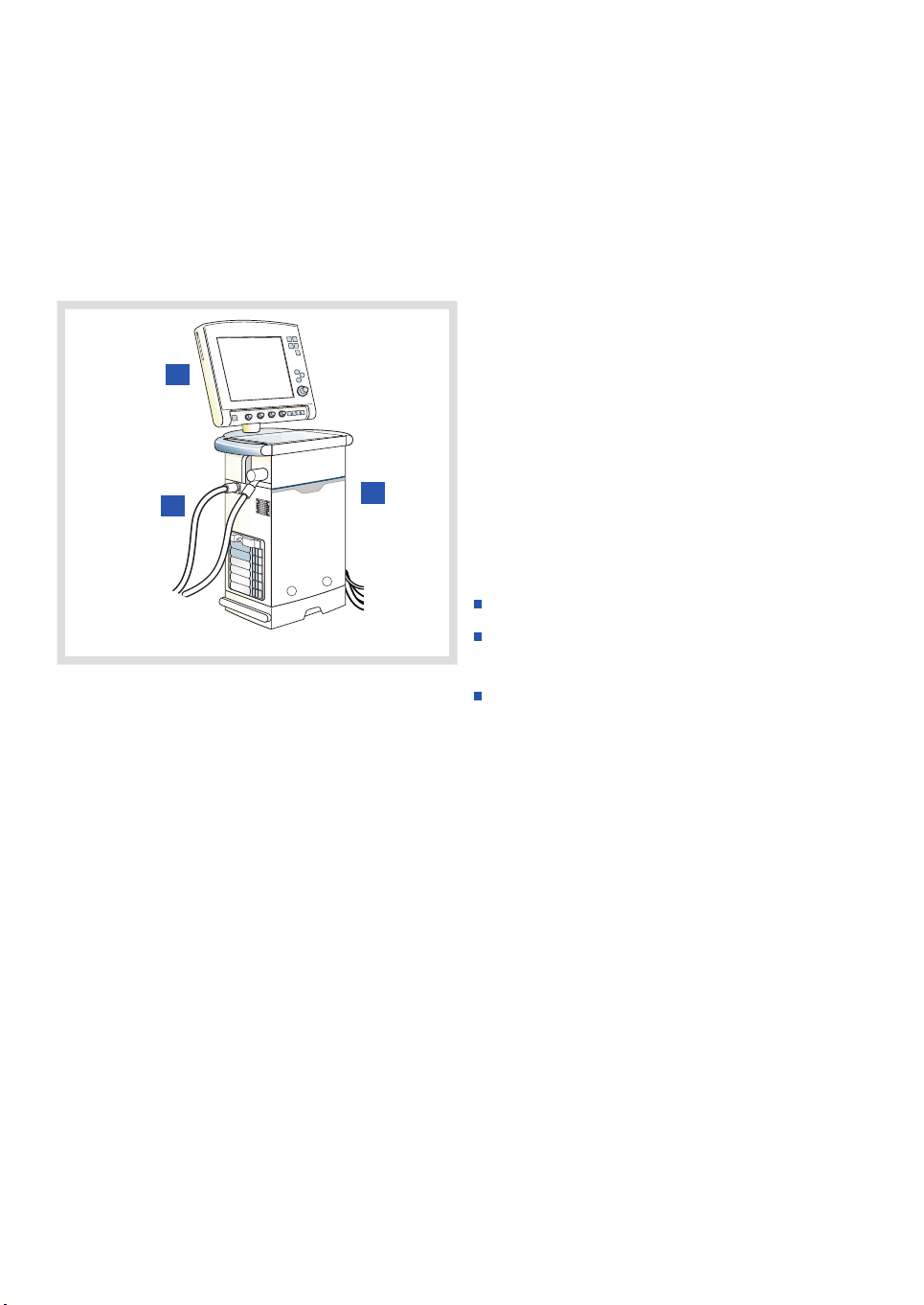
The SERVO-i Ventilator System consists of
the following components:
1. User Interface—for setting ventilation
modes, displaying patient data, and
indicating alarms
2. Patient Unit—for mixing gases
3. Patient Breathing System—for delivering
and exchanging gases
6
SERVO-i VENTILATOR SYSTEM V7.0, User´s Manual
Page 7

| Introduction |
1 |
1.1.5 INTENDED USE ENVIRONMENT
The SERVO-i Ventilator System should be
used only:
in hospitals
in facilities whose primary purpose is to
provide healthcare
during transport of a patient within hospitals
or healthcare facilities
during MR examinations of patients if the
conditions in the SERVO-i MR Environment
declaration (order no. 66 71 670) are met
and an agreement with MAQUET is signed.
1.1.6 CLEANING AND MAINTENANCE
Please refer to the SERVO-i/s Cleaning and
Maintenance User's Manual.
1.1.7 SERVICING GUIDELINES
CAUTIONS:
Regular Service: The SERVO-i Ventilator
System must be serviced at regular
intervals by MAQUET authorized
personnel who have received specialized
training.
Complete Service Records: All service
performed on the SERVO-i Ventilator
System must be recorded in a service
log in accordance with hospital
procedures and local and national
regulations.
Service Contract: We strongly
recommend that all service on the
SERVO-i Ventilator System should be
performed as part of a service contract
with MAQUET.
SERVO-i VENTILATOR SYSTEM V7.0, User´s Manual
7
Page 8

| Introduction |
| 1
1.1.8 DISCLAIMERS
Improper Use Environment
MAQUET has no responsibility for the safe
operation of SERVO-i Ventilator System if
the Intended Use Environment requirements
specified in this document are not followed.
Nonprofessional Servicing
MAQUET has no responsibility for the safe
operation of the SERVO-i Ventilator System
if installation, service or repairs are
performed by persons other than MAQUET
authorized personnel.
8
SERVO-i VENTILATOR SYSTEM V7.0, User´s Manual
Page 9

| Introduction |
1 |
1.2 WARNING, CAUTION,
IMPORTANT AND NOTE
Follow these safety guidelines. Additional
warnings appear in context throughout this
document.
Information is highlighted with Warning,
Caution, Important or Note, where:
WARNING! Indicates critical information
about a potential serious outcome to the
patient or the user.
CAUTION: Indicates instructions that must
be followed in order to ensure the proper
operation of the equipment.
Important: Indicates information intended
to help you operate the equipment or its
connected devices easily and conveniently.
Note: Indicates information requiring special
attention.
1.2.1 GENERAL
This manual summarizes the functions and
safety features of the SERVO-i Ventilator
System. It is not all-inclusive and should not
be construed as a substitute for training.
WARNINGS!
Always perform a Pre-use check before
connecting the ventilator to a patient.
If any of the following occurs, discontinue
use of the ventilator and contact a
service technician:
- Unfamiliar pop-up windows on the
screen
- Unresolvable alarms
- Unfamiliar sounds
- Any unfamiliar or unexplained event
Keep the ventilator upright during use.
Make sure that ventilation is started when
a patient is connected to the ventilator.
When the ventilator is in Standby, a
flashing message, Patient not ventilated,
is displayed as a reminder directly above
the word Standby.
When the ventilator is connected to a
patient:
- Do not lift or disconnect the expiratory
cassette.
- Continuously monitor the settings and
measurements displayed on the
screen.
- Make sure a resuscitator is readily
available.
SERVO-i VENTILATOR SYSTEM V7.0, User´s Manual
The SERVO-i Ventilator System must be
operated only by authorized personnel
who are well trained in its use. It must be
operated according to the instructions in
this User´s Manual.
9
Page 10

| Introduction |
| 1
Do not modify or remove any original
parts.
Do not cover the ventilator in any way,
since the functioning of the equipment
may be adversely affected.
When the ventilator is used for MCare
Remote Service, use only network
equipment that is safe and in compliance
with the relevant electrical and EMC
standards such as IEC-60950.
Note: The network cable is excluded
from this requirement.
Always disconnect the network cable
before starting ventilation when the
ventilator is used for MCare Remote
Service.
Positive pressure ventilation can be
associated with the following adverse
events: barotrauma, hypoventilation,
hyperventilation or circulatory
impairment.
The SERVO-i Ventilator System should
not be used in MR environments unless
the requirements described in the
SERVO-i MR Environment Declaration
(order no. 66 71 670) are met and an
agreement with MAQUET is signed.
The SERVO-i Ventilator System is not
intended to be used during radiotherapy,
since this may cause system malfunction.
The SERVO-i Ventilator System must not
be used in a hyperbaric chamber unless
it is equipped for hyperbaric oxygenation.
The SERVO-i Ventilator System must not
be used with helium without the Heliox
option.
Only accessories, supplies, and auxiliary
equipment recommended by MAQUET
should be used with the ventilator
system. Use of any other accessories,
spare parts or auxiliary equipment may
cause degraded system performance
and safety.
The power supply cord must be plugged
directly into the mains power outlet
without the use of any multiple socket
outlets. If a multiple socket outlet is used
together with other products, total
leakage current might be exceeded at
earth fault.
CAUTIONS:
In USA, Federal law restricts this device
to sale by or on the order of a physician.
The expiratory channel and expired gas
from the exhaust port may be
contaminated.
Refer to the Installation instructions to
assemble the system or options to obtain
a proper mechanical assembly.
Service, repair and installation must be
performed by MAQUET authorized
personnel only.
When lifting or moving the ventilator
system or parts of the system, follow
established ergonomic guidelines, ask
for assistance, and take appropriate
safety precautions.
Before use, make sure the system
version displayed under Status
corresponds to the system version
described in the User´s Manual.
10
SERVO-i VENTILATOR SYSTEM V7.0, User´s Manual
Page 11

| Introduction |
1 |
Extra care should be taken when
handling tubes, connectors and other
parts of the patient circuit. The use of a
support arm to relieve the patient from
the weight of the tubing system is
recommended.
When using the MCare Remote Service
function, install the network cable so that
there is no risk of anyone tripping over
it.
Do not leave the patient unattended
when connected to the ventilator.
MAQUET has no responsibility for the
safe operation of the SERVO-i Ventilator
System if the Intended Use requirements
specified in this document are not
followed.
Contact a MAQUET representative
regarding decommissioning of the
equipment.
Disconnect the mains power cable from
the outlet to isolate the ventilator from
mains power.
Do not touch accessible connector
contacts and the patient simultaneously.
Important:
Always use a heat and moisture
exchanger (HME) or equipment to
prevent dehydration of lung tissue.
While the SERVO-i Ventilator System is
in use, the wheels of the carrier shall be
locked and the carrier shall be in a
horizontal position.
Securely attach all cables, etc, to
minimize the risk of unintentional
disconnection.
Extra care should be taken when
handling the gas trolley, as it may tip
over.
All excess fluids must be disposed
according to hospital routines.
SERVO-i VENTILATOR SYSTEM V7.0, User´s Manual
11
Page 12

| Introduction |
| 1
1.2.2 POWER SUPPLY
WARNINGS!
The power cord must be connected only
to a properly grounded AC electrical
outlet to avoid the risk of electrical shock.
To guarantee reliable battery backup,
two fully charged battery modules must
be installed at all times.
CAUTIONS:
Do NOT use antistatic or electrically
conductive tubing with this system.
Avoid contact with external electrical
connector pins.
Unused module compartments should
always contain an empty module to
protect the electrical connector pins from
spillage and dust.
1.2.3 FIRE HAZARD
WARNINGS!
Keep the system and its gas hoses clear
of all ignition sources.
Do not use the system with worn or
frayed hoses or hoses that have been
contaminated by combustible materials
such as grease or oil.
Oxygen-enriched gas is extremely
flammable: if you detect a burning odor,
disconnect the oxygen supply, mains
power and remove the batteries.
Make sure that both the mains power
outlet and the power supply connector
are accessible.
12
SERVO-i VENTILATOR SYSTEM V7.0, User´s Manual
Page 13

| Introduction |
1 |
1.2.4 GASES
CAUTION: The system is not intended to
be used with any anesthetic agent.
Important:
Supplied gases shall meet the
requirements for medical grade gases
according to applicable standards.
Maximum levels:
Air
H2O < 7 g/m
Oil < 0.5 mg/m
3
3
Chlorine: must not be detectable
Oxygen
H2O < 20 mg/m
Oil < 0.3 mg/m
3
3
Note: For devices with serial numbers
below 70000 that are updated to version
7.0, the maximum inlet gas pressure will be
reduced (see the Technical data chapter on
page 222).
1.2.5 AUXILIARY EQUIPMENT
CAUTIONS:
Accessories, supplies, and auxiliary
equipment used with the ventilator
should:
- be recommended by MAQUET
- meet EN/IEC 60601-1standards
- meet IEC standards as a whole system
If a scavenging system (i.e. gas
evacuation) is connected to the ventilator,
it must conform to ISO8835-3 guidelines
for subatmospheric pressure and
1
induced flow.
Measurements of parameter values that
have been processed by auxiliary
equipment:
- may be inaccurate if equipment not
authorized by MAQUET is used
- should be discounted if they conflict
with information on the ventilator
screen
- must not substitute for therapeutic or
diagnostic decisions
Note: Applied parts, i.e. equipment making
physical contact with the patient, comprise
nebulizer patient unit and cable, Y Sensor,
CO2 sensor, Edi Catheter and cable and the
Ventilator Breathing System described in
System Flow Chart, Ventilation, Patient
Connection, part no. 66 92 522.
1. If the compressed air is generated by a liquid ring compressor there is a potential risk of chlorine in the supplied
air.
SERVO-i VENTILATOR SYSTEM V7.0, User´s Manual
13
Page 14

| Introduction |
| 1
1.3 VERSION AND CONFIGURATIONS
This manual applies to version 7.0 of the SERVO-i Ventilator System, which can be delivered
in three configurations: SERVO-i Infant; SERVO-i Adult and SERVO-i Universal.
1.3.1 CONFIGURATIONS
The weight ranges served by each configuration of the SERVO-i Ventilator System.
The SERVO-i Ventilator System can be used in both invasive and non invasive ventilation.
Configuration
ventilation
Universal
NIV = Non Invasive Ventilation
Adult
Weight range
Non invasive ventilationInvasive
Infant
NIV NAVA InfantNIV PC + PS
NIV Nasal
CPAP
0.5 kg – 10 kg0.5 kg – 30 kg3 kg – 30 kgNot Applicable0.5 kg – 30 kgSERVO-i Infant
Not ApplicableNot ApplicableNot Applicable10 kg – 250 kg10 kg – 250 kgSERVO-i Adult
0.5 kg – 10 kg0.5 kg – 30 kg3 kg – 30 kg10 kg – 250 kg0.5 kg – 250 kgSERVO-i
14
SERVO-i VENTILATOR SYSTEM V7.0, User´s Manual
Page 15
| Introduction |
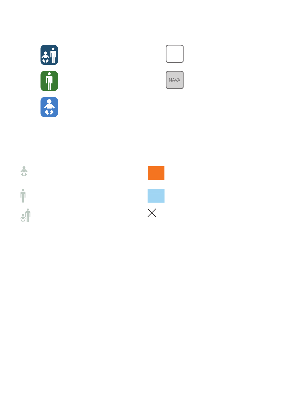
1.3.2 CONFIGURATION LABELS
NAVA readySERVO-i Universal
NAVASERVO-i Adult
SERVO-i Infant
1.3.3 AVAILABLE OPTIONS
The SERVO-i Ventilator System Configurations - lists the available functions and indicates if
included or optional with each configuration
1 |
Infant
Standard
Configuration
OptionsAdult
Not applicableUniversal
SERVO-i VENTILATOR SYSTEM V7.0, User´s Manual
15
Page 16

| Introduction |
| 1
NIV NAVA
NAVA
Nasal CPAP
Non Invasive
Ventilation (NIV)
Y Sensor Measuring
CO2 Analyzer
Nebulizer
Heliox
Stress Index
Open Lung Tool
®
(OLT)
Automode
®
Bi-Vent
VS (Volume Support)
PRVC (incl. SIMV
(PRVC) + PS)
VC (incl. SIMV (VC) +
PS)
PC (incl. SIMV (PC) +
PS)
PS/CPAP
16
SERVO-i VENTILATOR SYSTEM V7.0, User´s Manual
Page 17

2 SYSTEM OVERVIEW
TABLE OF CONTENTS
2.2
symbols
| System Overview |
18|Ventilator2.1
19|User Interface - Connections, labels and
22|Navigating the User Interface2.3
28|Patient Unit - Connections, labels and symbols2.4
34|Transport and storage2.5
2 |
SERVO-i VENTILATOR SYSTEM V7.0, User´s Manual
17
Page 18
| System Overview |
| 2
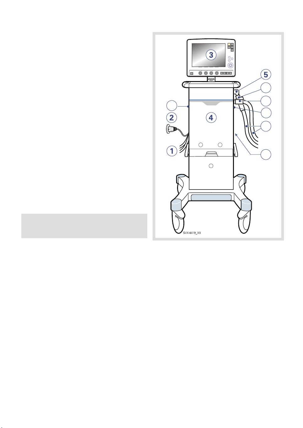
2.1 VENTILATOR
The User Interface is used to control ventilator
settings. Settings may be adjusted using
touchpads on the screen or a rotary dial.
Breathing parameters are continuously
measured and controlled. A difference
between the actual measured value of a
parameter and the preset or calculated value
results in the adjustment of gas delivery to
achieve the target value.
The system has two gas modules, one for air
and one for O2. Gases may be supplied by a
medical pipeline system, a compressor, or by
gas tanks.
Ensure that the ventilator is in its locked
position on the cart or holder used, to prevent
unintentional movements.
CAUTION: Lock the wheels if the ventilator
is not to be used for transportation.
6
10
7
10
8
9
1. Air and O2 supply
2. Power cable
3. User Interface
4. Patient Unit
5. Expiratory inlet
6. Servo Duo Guard, viral/bacterial filter
7. Inspiratory outlet
8. Patient circuit
9. Module compartment
10. Emergency air intake
18
SERVO-i VENTILATOR SYSTEM V7.0, User´s Manual
Page 19
| System Overview |
2.2 USER INTERFACE - CONNECTIONS, LABELS AND SYMBOLS
The User Interface includes:
a screen with active touchpads
fixed keys
rotary dials
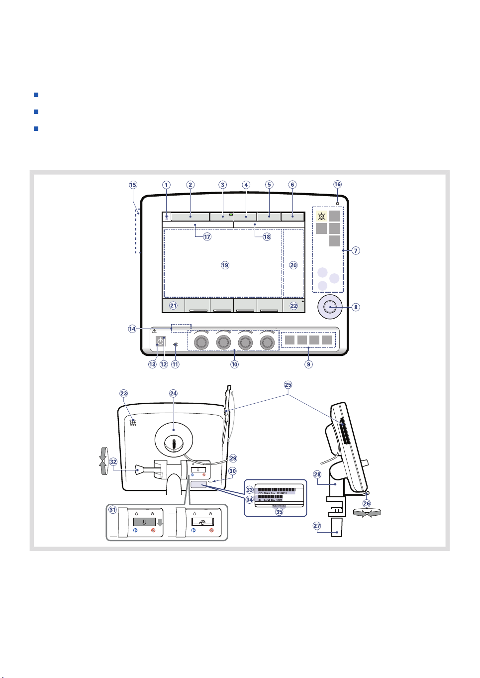
2.2.1 USER INTERFACE DIAGRAM
2 |
SERVO-i VENTILATOR SYSTEM V7.0, User´s Manual
19
Page 20

| System Overview |
| 2
2.2.2 USER INTERFACE COMPONENTS
Refer to the User Interface Diagram for the location of the following numbered components:
1. Current Patient category
2. Current mode of ventilation
3. Automode On/Off (option)
4. Admit patient/Entered patient data and
admission date
5. Nebulizer On/Off (option)
6. System status parameters
7. Fixed keys
8. Main Rotary Dial—used to select a menu
touchpad or parameter box, to adjust
values, and to confirm settings
9. Special Function Keys—used to start
special ventilatory functions
10. Direct Access Knobs—used for immediate
adjustment of breathing parameters
11. AC Power indicator (green)
12. Standby indicator (yellow)—when the
ventilator is in Standby, a flashing
message, Patient not ventilated, is
displayed on the screen directly above the
word Standby.
13. Start/Standby key
14. On/Off switch (rear side)
15. Slot for Ventilation Record Card (front
view)
16. Luminescence detector—for automatically
adjusting screen brightness
17. Text messages, including patient
triggering symbols
18. Alarm messages
19. Waveform area—for monitoring two to
four individually scaled parameters,
including a volume/pressure loop and a
flow/volume loop
20. Measured values and alarm limits display
(customizable)
21. Additional settings
22. Additional measured values
23. Loudspeaker
24. Cable reel for the control cable
25. Slot for Ventilation Record Card (side/rear
view)
26. Locking lever for rotation
27. Locking screw for alternative cart
mounting
28. Holder for positioning on the Mobile Cart
29. Control cable (2.9 m long)
30. Service connector
31. On/Off switch
32. Locking lever for tilting
33. Model number
34. Serial number
35. Manufacturing information
20
SERVO-i VENTILATOR SYSTEM V7.0, User´s Manual
Page 21
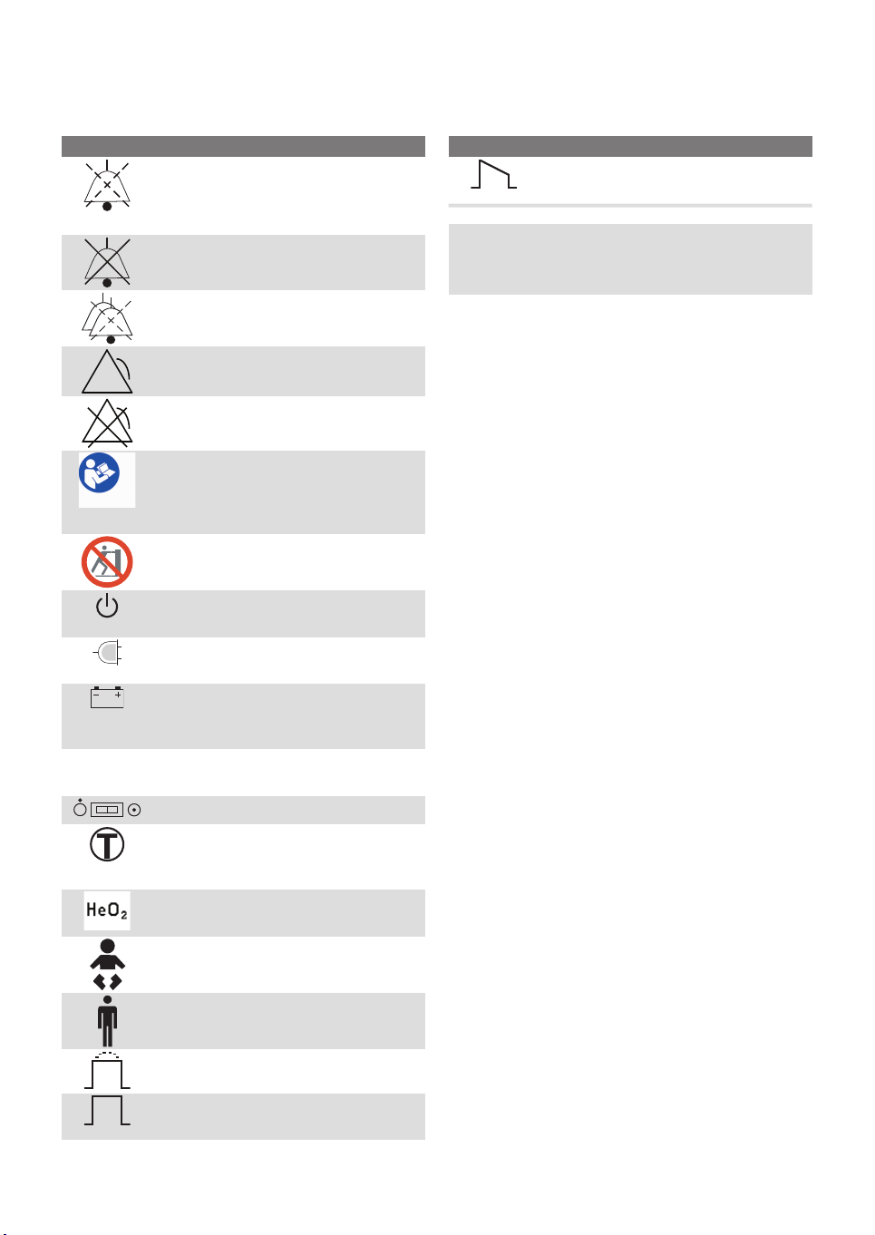
2.2.3 USER INTERFACE SYMBOLS
| System Overview |
2 |
12 V
DescriptionSymbol
Audio Pause - silence or confirm an
alarm. Note: This symbol may be
different depending on User interface
version.
Audio off
Audio Pause - all alarms, active and
inactive, are pre-silenced.
Alarm on
Alarm off
Attention—consult documentation
Note: This symbol may be different
depending on User Interface version
Do not push the User Interface as the
ventilator may tip over.
Start ventilation/Standby—yellow
indicates Standby
Power indicator—green indicates AC
power connected
Battery—indicates ventilator is using
battery power, with estimated
minutes remaining
12 V - indicates that external 12V DC
is connected.
ON/OFF switch
Trigger indication—appears in the
message/alarm field when the patient
triggers a breath
Indicates that the system is
compensated for Heliox.
Infant patient category
DescriptionSymbol
Volume Control with decelerating
flow
Note: The patient unit symbols are
described later in this chapter.
Adult patient category
Volume Control with flow adaptation
Volume Control without flow
adaptation
SERVO-i VENTILATOR SYSTEM V7.0, User´s Manual
21
Page 22
| System Overview |
| 2
2.3 NAVIGATING THE USER INTERFACE
The following subsections provide general
procedures for working with the user interface.
More detailed procedures for specific tasks
are found in later chapters and in the
Appendix.
2.3.1 TOUCH SCREEN
To adjust ventilator settings:
1. Open the desired window by pressing one
of the touchpads on the screen or one of
the fixed keys.
2. Activate the desired touchpad by pressing
it.
The touchpad is now highlighted in white
with a blue frame and it is possible to set
a new value.
3. Turn the Main Rotary Dial to the desired
value.
4. Confirm the settings by pressing the
parameter touchpad or by pressing the
Main Rotary Dial.
5. The touchpad turns grey again indicating
that the new setting has been entered.
6. Press Accept to activate the new settings,
or Cancel to start over.
Important: Different ways of interacting
with the screen will affect its lifetime. Never
use any sharp or pointed objects, such as
ballpoint pens, on the screen.
22
SERVO-i VENTILATOR SYSTEM V7.0, User´s Manual
Page 23
| System Overview |
2 |
2.3.2 MAIN ROTARY DIAL
SVX-6021_XX
To use an alternative method for adjusting
ventilator settings once the desired menu is
activated:
1. Turn the Main Rotary Dial until the desired
menu touchpad is marked with a blue
frame.
4. Confirm the setting by pressing the Main
Rotary Dial.
The parameter touchpad turns grey again
indicating that a new setting has been
entered.
5. Touch Accept to activate your settings,
or Cancel to start over.
Note: When the defined safety limits for a
given parameter have been reached, the
Main Rotary Dial becomes inoperative for
2 seconds to indicate that a limit has been
reached.
2. Press the Main Rotary Dial to confirm.
The menu touchpad is highlighted in white
with a blue frame, indicating that a new
value can be entered.
3. Turn the Main Rotary Dial to the desired
value or line.
SERVO-i VENTILATOR SYSTEM V7.0, User´s Manual
23
Page 24
| System Overview |
| 2
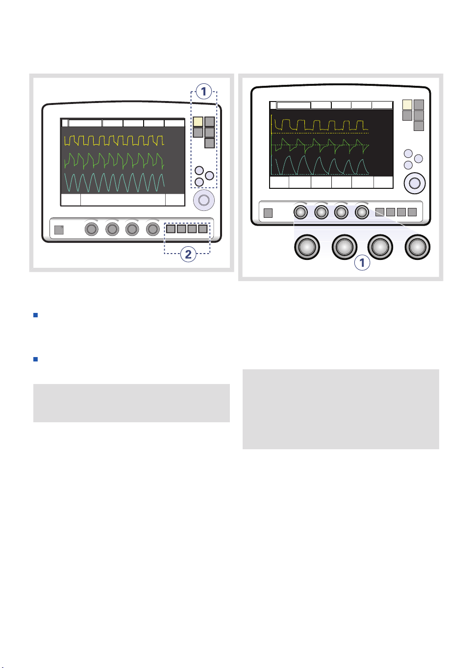
2.3.3 FIXED KEYS
There are two groups of fixed keys on the user
interface screen:
The keys in group 1 activate user interface
functions such as Save and access various
screens such as Menu.
The keys in group 2 start special ventilatory
functions
Important: The special ventilatory
functions require continuous supervision.
2.3.4 DIRECT ACCESS KNOBS
Using Direct Access Knobs
To adjust a breathing parameter directly:
1. Turn the Direct Access Knob
corresponding to the parameter you wish
to change until the desired value is
displayed on the screen.
WARNING! When you adjust a breathing
parameter using a Direct Access Knob, the
parameter will change immediately starting
with the next breath; no additional
confirmation is required.
The four dials along the bottom of the User
Interface screen are the Direct Access Knobs.
They permit direct control of four breathing
parameters, which are automatically selected
depending on ventilation mode.
24
The Main Rotary Dial and Direct Access Knobs
become inoperative for 2 seconds when the
user reaches a defined safety limit for the
parameter being adjusted.
SERVO-i VENTILATOR SYSTEM V7.0, User´s Manual
Page 25
| System Overview |
2 |
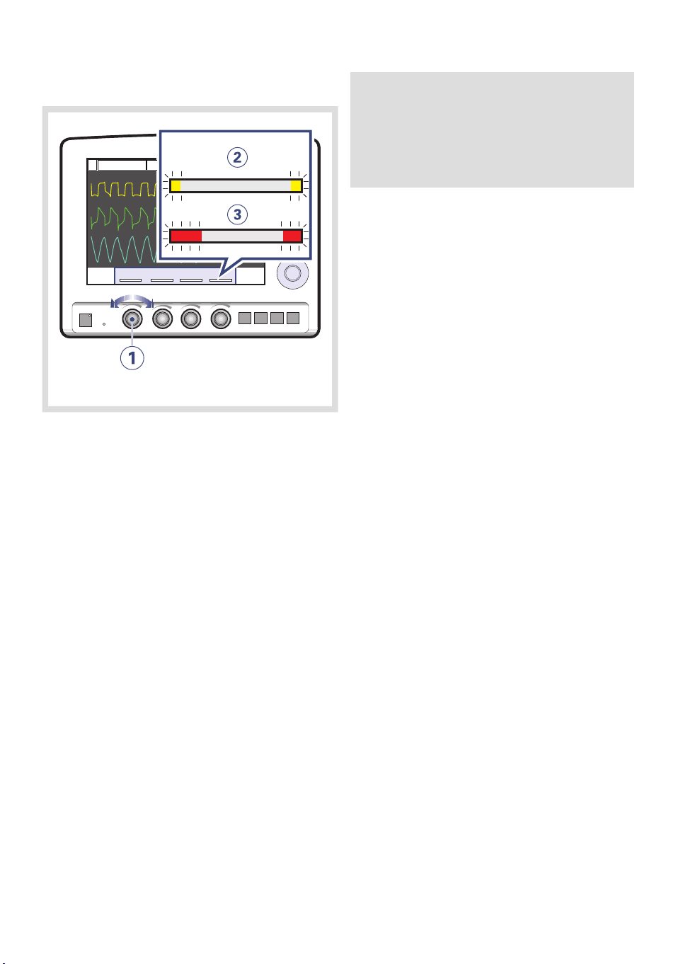
Direct Access Knobs - Safety
The four Direct Access Knob parameters are
displayed at the bottom of the screen with
color-coded bars that indicate whether the
parameter values are within
generally-recognized safety limits.
Note: When the defined safety limits for a
given parameter have been reached, the
Direct Access Knob becomes inoperative
for 2 seconds to indicate that a safety limit
has been reached.
The figure above shows the following
components.
1. A Direct Access Knob
2. A yellow bar indicating the corresponding
parameter value is outside safety limits; a
text message is displayed accompanied
by an audible signal.
3. A red bar indicating the corresponding
parameter value is significantly outside
safety limits; a text message is displayed
accompanied by an audible signal.
SERVO-i VENTILATOR SYSTEM V7.0, User´s Manual
25
Page 26
| System Overview |
| 2
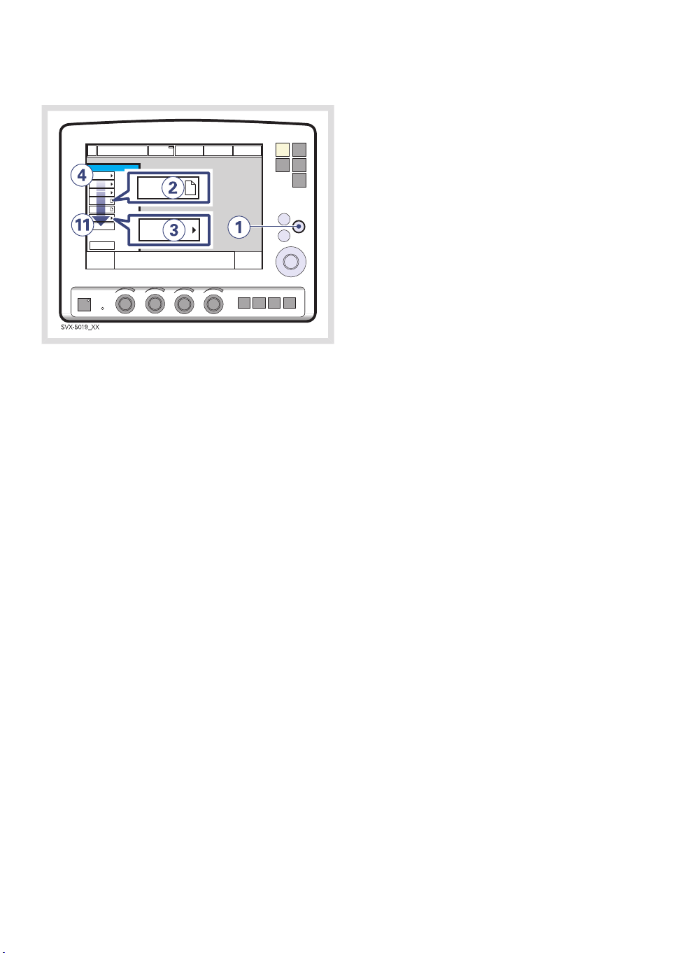
2.3.5 MENU KEY
To access the user interface windows:
1. Press the fixed key Menu.
Touchpads leading to the user interface
windows appear.
2. If the touchpad shows a sheet icon, press
the touchpad to open a user interface
window, OR
3. If the touchpad shows an arrow icon,
press the touchpad to display the
submenu.
Press any of the following touchpads.
4. Alarm
5. Review
6. Options
7. Compensate
8. Copy (to Ventilation Record Card)
9. Biomed
10. Panel lock
11. Change patient category (option)
For more information see Appendix • User
interface on page 253.
26
SERVO-i VENTILATOR SYSTEM V7.0, User´s Manual
Page 27
| System Overview |
2 |
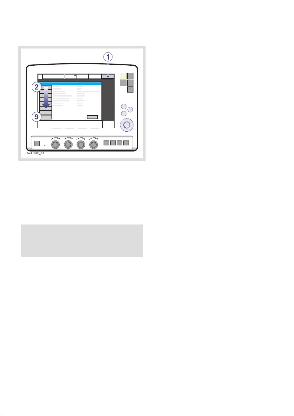
2.3.6 STATUS TOUCHPAD
The Status touchpad indicates the power
supply currently being used by the ventilator
(AC power, battery power, or external 12V DC
power). If the ventilator is running on battery
power, the estimated remaining battery time
in minutes is shown.
To access the status window:
1. Press the Status touchpad.
Touchpads leading to status windows appear.
Press any of the following touchpads.
2. General
3. O2 cell / O2 Sensor
4. Expiratory cassette
5. Batteries
6. Modules - CO2 module (if fitted), Y Sensor
measuring (if fitted), Edi module (if fitted)
7. Installed Options
8. Pre-use check
9. Patient Circuit
CAUTION: When using an external 12V DC
supply, battery modules must be installed
to ensure proper operation.
SERVO-i VENTILATOR SYSTEM V7.0, User´s Manual
27
Page 28
| System Overview |
| 2
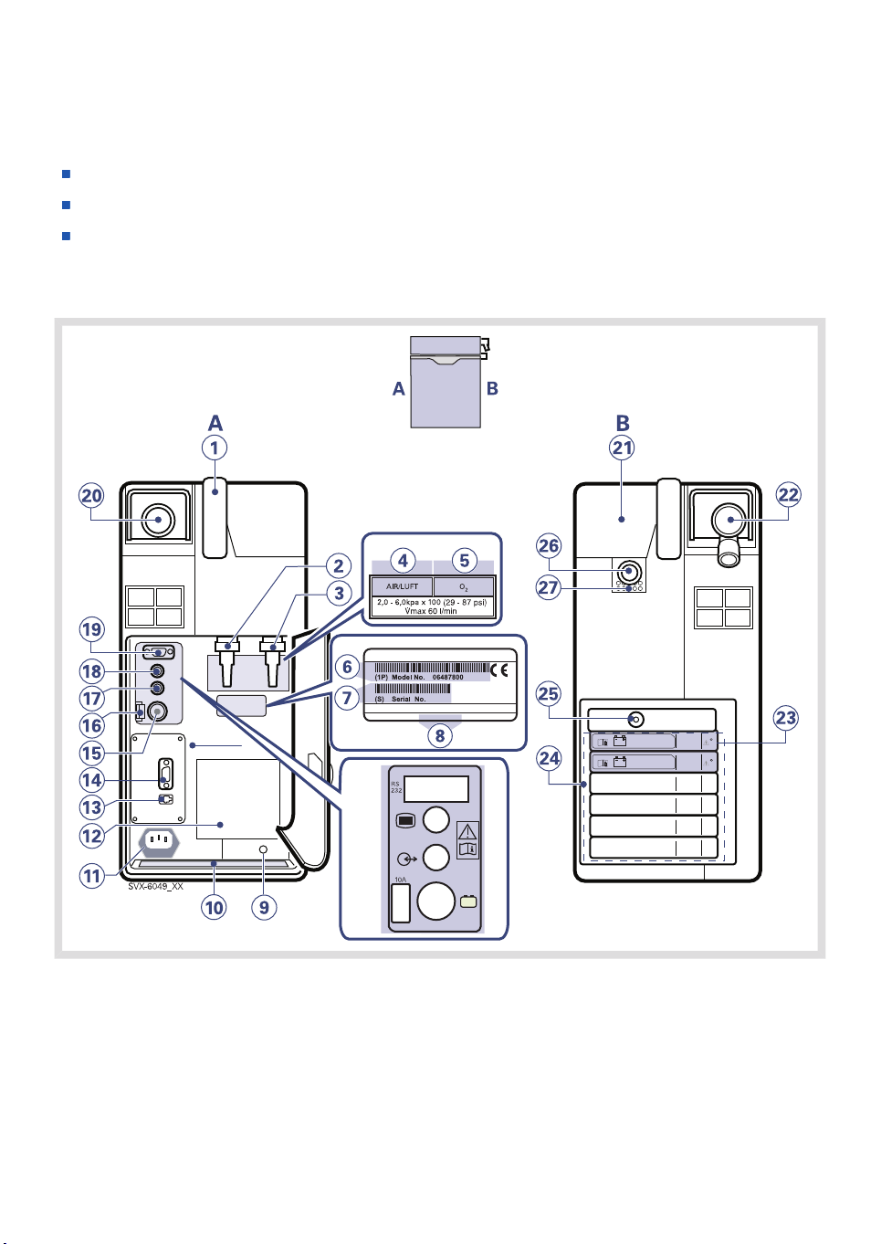
2.4 PATIENT UNIT - CONNECTIONS, LABELS AND SYMBOLS
The patient unit consists of the following components:
gas supplies and their connectors
power supplies and their connectors
connectors for accessories
2.4.1 PATIENT UNIT DIAGRAM
28
0123
-
+
12V
SERVO-i VENTILATOR SYSTEM V7.0, User´s Manual
Page 29

| System Overview |
2.4.2 PATIENT UNIT COMPONENTS
Refer to the Patient Unit Diagram for the location of the following numbered components:
B
A
21. Cover, inspiratory channel
1. Handle
2. Gas inlet for air
3. Gas inlet for O
4. Air / Luft
5. O
2
6. Model number
2
22. Expiratory inlet
23. Battery lock
24. Module compartment
25. Nebulizer connector
26. Inspiratory outlet
27. Emergency air intake
7. Serial number
8. Manufacturing information
9. Equipotentiality terminal
10. Label
11. AC power supply connector with fuse
12. Cooling fan with filter
2 |
13. Alarm output connection
14. RS-232 connector
15. External +12V DC inlet
16. Fuse for external DC power supply
17. Optional connector
18. User interface connector
19. RS-232 connector
20. Expiratory outlet
SERVO-i VENTILATOR SYSTEM V7.0, User´s Manual
29
Page 30
| System Overview |
| 2
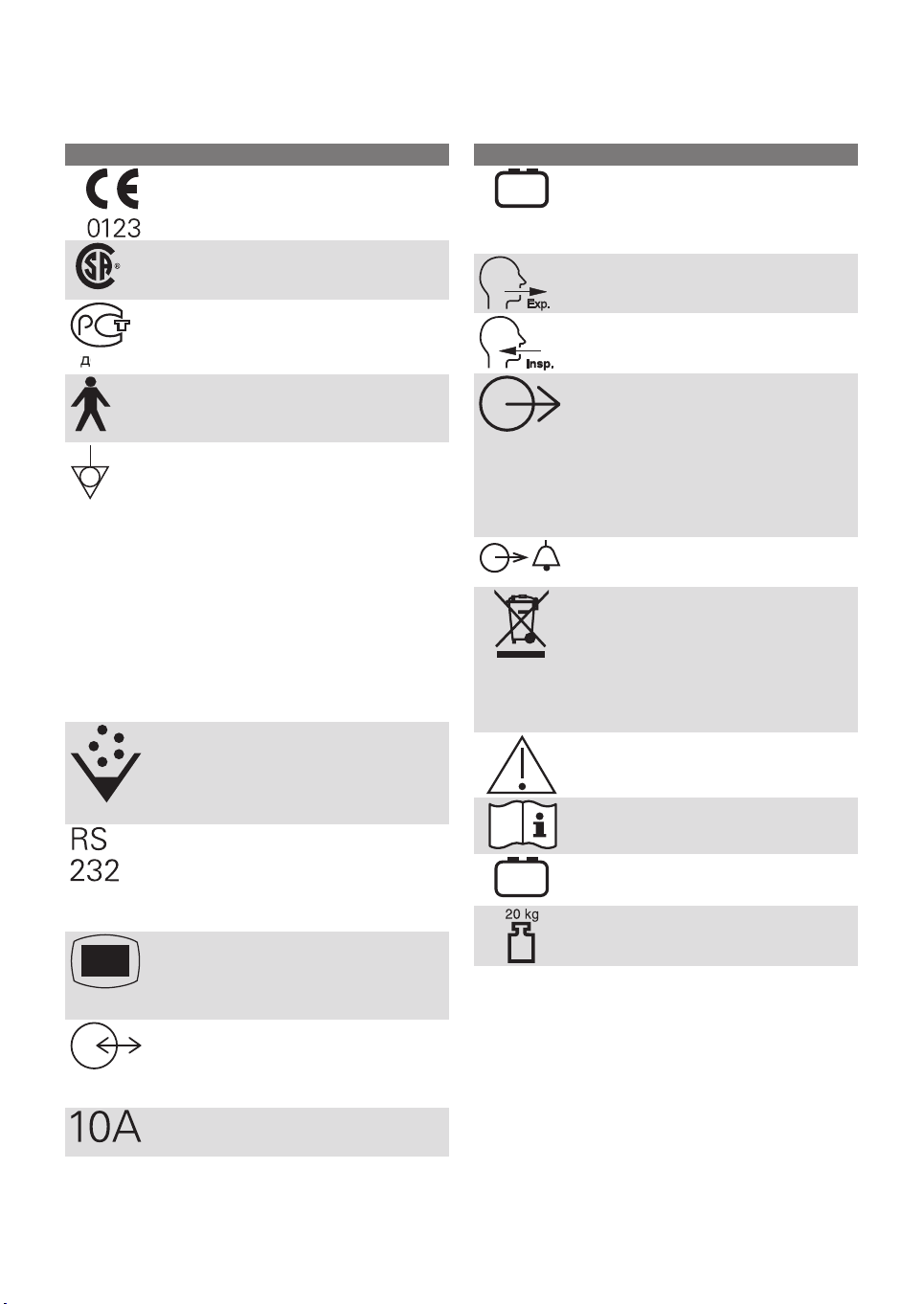
2.4.3 PATIENT UNIT SYMBOLS
& 86
E 01
ExplanationSymbol
CE label—indicates compliance with
the requirements of the Medical
Device Directive 93/42/EEC
CSA label—Indicates compliance
with Canadian and US standards
PCT label - indicates compliance with
Russian standards
Class I equipment, Type B—indicates
classification according to IEC
60601-1/EN 60601-1
Equipotentiality terminal
Note: The equipotentiality terminal
is designed for the connection of a
potential equalization conductor
according to DIN 42 801 and
EN/IEC 60601-1. The function of the
equipotentiality terminal is to equalize
potentials between the system and
other medical electrical devices that
can be touched simultaneously. The
equipotentiality terminal must not be
used for a protective earth
connection.
Nebulizer Connector
-
+
12V
ExplanationSymbol
External 12V DC input
Note: This symbol may be different
depending on Patient Unit version.
Expiratory label—gas flow from
patient.
Inspiratory label—gas flow to patient.
Gas exhaust port label—exhaust gas
flow from ventilator
Note: This port should not be
connected to a spirometer because
the volume through the exhaust port
is not equal to the expired volume
from the patient.
Alarm output connection—external
alarm output communication
Special waste. This product
contains electronic and electrical
components. Discard disposable,
replaced and left-over parts in
accordance with appropriate
industrial and environmental
standards.
Caution
30
RS 232 / Serial port—connector for
data communication.
Note: This symbol may be different
depending on Patient Unit version.
User Interface connector
Note: This symbol may be different
depending on Patient Unit version.
Optional connector / Expansion
Note: This symbol may be different
depending on Patient Unit version.
10A Fuse for external DC power
supply.
Consult Instructions for use
-
Batteries
+
Weight - Patient unit and User
interface.
SERVO-i VENTILATOR SYSTEM V7.0, User´s Manual
Page 31

2.4.4 PATIENT UNIT GAS FLOW DIAGRAM
| System Overview |
2 |
12
2
1
SVS-0099_EN
3 4
11
10
5
6
7
to Patient
9
8
from Patient
SERVO-i VENTILATOR SYSTEM V7.0, User´s Manual
31
Page 32

| System Overview |
| 2
2.4.5 GAS FLOW THROUGH THE PATIENT UNIT
Refer to the Patient Unit gas flow diagram for
the location of the following numbered
components:
1. Gas inlet for O
2
2. Gas inlet for air
3. The gas flow is regulated by the gas
modules for Air and O2.
4. The gases are mixed in the inspiratory
mixing section.
5. The Oxygen concentration can be
measured with an O2 cell or O2 sensor.
An O2 cell is shown here.
The O2 cell is protected by a bacteria filter.
6. The pressure of the mixed gas delivered
to the patient is measured by the
Inspiratory pressure transducer.
The transducer is protected by a bacterial
filter.
7. The inspiratory channel delivers the mixed
gas to the patient systems inspiratory
tubing. The inspiratory channel also
contains a safety valve.
8. The patient breathing systems expiratory
tubing is connected to the expiratory inlet.
The inlet also contains a moisture trap.
9. The gas flow through the expiratory
channel is measured by ultrasonic
transducers.
10. The expiratory pressure is measured by
the expiratory pressure transducer
(located inside the ventilator). The
transducer is protected by a bacterial filter
inside the expiratory cassette.
11. The pressure (PEEP) in the patient system
is regulated by the expiratory valve.
12. Gas from the patient system leaves the
ventilator via the expiratory outlet. The
outlet contains a non-return valve.
Note: The expiratory cassette can be
exchanged between different SERVO-s and
SERVO-i Ventilator Systems. Always
perform a Pre-use check after exchanging
an expiratory cassette.
32
SERVO-i VENTILATOR SYSTEM V7.0, User´s Manual
Page 33

2.4.6 SYMBOLS ON ACCESSORIES AND PACKAGING
| System Overview |
2 |
QTY
ExplanationSymbol
Order number
Number to identify the production
batch
Quantity
Outer diameter in millimeters
Inner diameter in millimeters
Circumference/lengthFr/cm
Use by date
Do not re-use. Single use only.
Do not use if packaging is damaged
Attention—consult documentation
Keep away from sunlight
Method of sterilization using
irradiation
Manufacturer
CE label—indicates compliance with
the requirements of the Medical
Device Directive 93/42/EEC
Manufacturing date
Phthalates
o
-10
C
PHT
ExplanationSymbol
Humidity limitation
+55oC
Temperature limitation
Phthalate free
Defibrillation proof Type CF applied
part - indicates classification
according to IEC 60601-1
Output
Type BF applied part — indicates
classification according to IEC
60601-1/EN 60601-1
Type B—indicates classification
according to IEC 60601-1/EN
60601-1
Fragile - handle with care
Keep away from water
This way up - indicates correct
upright position of the transport
package
Atmospheric pressure limitation
Do not expose the battery to heat or
fire.
Rx
sale by or on the order of a physician.
ONLY
Recycling. Worn-out batteries must
be recycled or disposed of properly
in accordance with appropriate
industrial and environmental
standards.
Federal law restricts this device to
Hazardous waste
(infectious)
SERVO-i VENTILATOR SYSTEM V7.0, User´s Manual
Hazardous waste (infectious) The
device contains parts which must not
be disposed of with ordinary waste.
Indicates the inner diameter of the
endotracheal tube.
Do not expose the battery to
mechanical force.
Do not dismantle, open or shred the
battery.
The support arm must be folded
during transport.
Consult Instructions for use
33
Page 34

| System Overview |
| 2
2.5 TRANSPORT AND STORAGE
2.5.1 BEFORE INTRAHOSPITAL TRANSPORT
Before transporting the ventilator with or
without a patient connected, follow facility
guidelines and:
Be sure the patient unit and the user
interface are securely attached and locked.
Be sure all accessories such as modules,
gas cylinders, and humidifier are securely
attached and locked.
Be sure the gas cylinders are connected
and have sufficient gas.
Be sure the batteries are fully charged.
Important: At least two batteries should
be connected during transport.
Inspect the resuscitator.
Inspect the Mobile Cart for damage.
Be sure the straps are firmly wrapped
across the center of the gas cylinders so
that the cylinders do not move during
transport.
Be sure that the support arm is folded
before transport.
2.5.2 DURING INTRAHOSPITAL
TRANSPORT
While transporting the ventilator with or
without a patient connected, follow facility
guidelines and:
Use the handles on the Mobile Cart.
Transport the bed and the ventilator slowly,
and watch the patient connection carefully
to see that no pulling or other movement
occurs.
When moving the Support Arm or changing
position, watch the patient connection
carefully to see that no pulling or other
movement occurs.
Be careful not to tip the Mobile Cart when
crossing an obstacle like a doorstep.
34
SERVO-i VENTILATOR SYSTEM V7.0, User´s Manual
Page 35

2.5.3 STORAGE
When the SERVO-i Ventilator System is in
storage, keep the ventilator connected to
mains power to maintain full charge in the
batteries.
Do not dispose of battery modules and O
cells with ordinary waste.
Be sure the system is not exposed to
temperatures below +10oC or above +40oC.
Be sure the system is not exposed to a
relative humidity above 95%.
| System Overview |
2
2 |
SERVO-i VENTILATOR SYSTEM V7.0, User´s Manual
35
Page 36

| System Overview |
| 2
36
SERVO-i VENTILATOR SYSTEM V7.0, User´s Manual
Page 37

3 POWER SUPPLY
TABLE OF CONTENTS
| Power supply |
38|Introduction3.1
38|Viewing battery status3.2
40|Alarms and safety3.3
3 |
SERVO-i VENTILATOR SYSTEM V7.0, User´s Manual
37
Page 38

| Power supply |
| 3
3.1 INTRODUCTION
The SERVO-i Ventilator System is equipped
with an AC power supply with automatic range
selection. The ventilator will automatically
operate correctly using 100-120V AC or
220 - 240V AC outlets.
See chapter Technical data on page 221.
The ventilator is equipped with at least two
battery modules which automatically supply
12V DC power in case of an AC power failure,
ensuring that ventilator settings and stored
data remain intact in the event of an AC power
failure.
Note: Batteries can be added to available
slots during operation.
The ventilator also comes equipped with an
inlet for an external 12V DC power supply. This
power supply activates automatically in case
of an AC power failure, and ventilator settings
and stored data remain intact.
3.2 VIEWING BATTERY STATUS
When operating from batteries, the estimated
remaining battery time in minutes is displayed
in the upper right corner of the screen on the
Status touch pad.
WARNING! If the remaining battery time on
the Status touchpad is displayed in red, the
battery modules have very little operational
time left and battery modules must be
replaced. If possible, connect the ventilator
to AC power.
Note: The total usable backup time is the
sum of the estimated operation time
displayed for each battery module minus
10 minutes.
CAUTION: When using external 12V DC,
at least two installed battery modules are
required to ensure proper operation.
When the system is connected to an external
power supply, all connected battery modules
are being recharged. This does not affect
ventilation.
Alarms and Messages
See Alarms and Safety later in this chapter.
When the ventilator is turned off with the on/off
switch, batteries continue to charge.
38
SERVO-i VENTILATOR SYSTEM V7.0, User´s Manual
Page 39

| Power supply |
3 |
Detailed battery status information is available
via the Battery Status Window:
1. Press the Status touchpad at the top-right
of the user interface to display the Status
Window.
SVX-9033
2. Press the Batteries touchpad to display
the Battery Status Window.
The following information is displayed for each
mounted battery module:
Slot number
Serial number
Charge indicator, where
0 boxes filled = < 10% relative charge
1 box filled = 10-25% relative charge
2 boxes filled = 26-50% relative charge
3 boxes filled = 51-75% relative charge
4 boxes filled = 76-100% relative charge,
Remaining operating time in minutes
Activity Instruction—an instruction may be
displayed next to the remaining operating
time in minutes:
ResponseActivity Instruction
Expires soon
Replace battery
Order a new battery
module.
The battery no longer
reliable; replace it
immediately.
SVX-9032
SERVO-i VENTILATOR SYSTEM V7.0, User´s Manual
Note: If the Replace battery is displayed,
the battery has become unreliable,
regardless of the operating time displayed
in the Battery Status Window. In this
situation, replace the battery even when the
status window indicates significant
operating time remains.
39
Page 40

| Power supply |
| 3
3.3 ALARMS AND SAFETY
The status of the battery modules is
continuously monitored by the ventilator. If the
status is unsatisfactory, four types of
messages may be displayed at the top of the
user interface:
Technical Error Message
High Priority Alarm Message
Medium Priority Alarm Message
Text Message
3.3.1 WARNINGS
WARNINGS!
If a battery status message is displayed
on the user interface, check the battery
status as soon as possible. If no action
is taken, the ventilator may eventually
shut down.
To guarantee reliable battery backup,
two fully charged battery modules must
be installed at all times.
Always replace batteries when the
ventilator software notifies you of
imminent expiration or of diminished
operating capacity.
Do not disconnect and store battery
modules over long periods of time
because this will degrade their capacity.
If used battery modules need to be
stored for short periods of time (up to
one week), then store them fully charged
in a cool (15-20°C or 59-68°F), dry
environment.
Batteries that have been stored or
disconnected should be recharged
before use.
Dispose of batteries according to local
regulations and not with ordinary waste.
After a new battery module is installed,
display the Battery Status Window to
ensure safe battery operation.
When delivered, the battery modules may
not be fully charged. Check the status of
the batteries via the user interface and,
if necessary, charge the battery before
use by connecting the ventilator to the
power supply.
Always recharge discharged batteries.
When not in use, the ventilator should
always be connected to the power supply
to ensure fully charged batteries.
When the ventilator is running on
batteries, the Servo Ultra Nebulizer is
disabled to reduce power consumption.
40
SERVO-i VENTILATOR SYSTEM V7.0, User´s Manual
Page 41

3.3.2 STATUS MESSAGES
Check battery status (Text Message)
Nebulizer cannot be run on one battery (Text
message)
Battery mode! Nebulizer switched off (Medium
Priority Alarm)
Battery operation (Medium Priority Alarm)
Low battery voltage (High Priority Alarm)
| Power supply |
ExplanationMessage (message type)
Power failure.Technical error no. 1 - 6, 29, 10001 (technical error)
There is a problem with the battery modules. One
or more battery modules must be replaced.
When using an Aeroneb module installed by
MAQUET and any Aeroneb nebulizer unit,
nebulization cannot be maintained with less than
two batteries installed.
Ventilator is running on batteries and the Servo Ultra
Nebulizer has been disabled to reduce the power
consumption.
AC power is off line due to a power failure or
disconnection.
Less than 10 minutes left of battery operation.Limited battery capacity (High Priority Alarm)
Less than 3 minutes left of battery operation.No battery capacity (High Priority Alarm)
Battery voltage too low. Cannot guarantee
continued ventilator operation.
3 |
3.3.3 AC POWER FAILURE
In the event of an AC power failure or
disconnection, the ventilator switches to
battery operation and activates medium
priority alarms, see Table above in Status
Messages for details.
SERVO-i VENTILATOR SYSTEM V7.0, User´s Manual
41
Page 42

| Power supply |
| 3
42
SERVO-i VENTILATOR SYSTEM V7.0, User´s Manual
Page 43

4 OPERATION OVERVIEW
TABLE OF CONTENTS
| Operation overview |
44|Workflow summary4.1
44|Pre-use check4.2
52|Patient circuit test4.3
53|Select patient category (option).4.4
54|Enter the patient data4.5
55|Select the Type of Ventilation (Options)4.6
56|Set ventilation mode4.7
57|Set alarm limits4.8
58|Start ventilation4.9
59|Additional settings window4.10
60|Suctioning4.11
62|Re-adjust the Oxygen cell4.12
63|Disconnect the patient4.13
4 |
SERVO-i VENTILATOR SYSTEM V7.0, User´s Manual
43
Page 44

| Operation overview |
| 4
4.1 WORKFLOW SUMMARY
The following summary procedure provides
an overview of the operation of the SERVO-i
Ventilator System.
1. Turn on the ventilator and perform a
Pre-use check. When the ventilator is in
Standby, a flashing message, Patient not
ventilated, is displayed on the screen
directly above the word Standby.
2. Select patient category (option).
3. Enter data for the new patient, including
height and weight.
4. Select type of ventilation (option).
5. Set the ventilation mode.
6. Check, and if necessary, adjust the alarm
profile.
7. Connect ventilator to patient and start
ventilation.
8. During ventilation you can:
use the Additional Settings and Alarm
profile touchpads to review and adjust
settings
use suction support
adjust the O2 cell (not when O2 sensor
is used)
9. Disconnect the patient.
The following sections describe each of the
above steps in more detail.
4.2 PRE-USE CHECK
The Pre-use check includes tests and
measurements of:
internal technical functionality
gas supply
internal leakage
pressure transducers
safety valve
O2 cell / O2 sensor
flow transducers
battery modules
patient circuit leakage
patient circuit compliance
patient circuit resistance
WARNINGS!
Always perform a Pre-use check before
connecting the ventilator to a patient.
The volume of the patient circuit used
during Pre-use check should be the same
as, and must never be higher than, during
ventilation e.g. the active humidifier must
be filled before Pre-use check.
The separate Patient Circuit Test that can
be performed in Standby does not
replace the Pre-use check.
If any malfunctions are detected during
the start-up procedure, see chapter
System messages for more information.
44
SERVO-i VENTILATOR SYSTEM V7.0, User´s Manual
Page 45

| Operation overview |
4 |
WARNINGS!
Do not connect the ventilator to a patient
while a malfunction persists.
Do not disconnect the expiratory
cassette while the ventilator is in
operation; if necessary, disconnect the
cassette while in Standby.
Important:
If you change the breathing circuit after
completion of the Pre-use check, perform
a new Pre-use check or a patient circuit
test.
When the Pre-use check is completed,
all possible sources of alarm signals have
been verified and the alarm system
operates correctly.
4.2.1 PRE-USE CHECK WITH HeO
2
The Pre-use check can be performed with
HeO2 instead of air if desired (only if Heliox
option is installed).
Always perform the Pre-use check on a warm
expiratory cassette when HeO2 is used. In
order for the expiratory cassette to get warm
enough, the system must be in the power-on
state for 15-30 minutes.
1. Follow the normal Pre-use check
procedure.
2. The HeO2 icon (1) indicates that the
ventilator is adjusted for Heliox use.
1
SVX-9042
Note: If the identified gas mixture is not
approved for use with the SERVO-i
Ventilator System (e.g. pure helium or Heliox
70:30), then the Gas supply test and O
cell/sensor test are not passed and the
Pre-use check will fail. The message
Unapproved gas mixture identified. Check
gas supply is displayed.
2
Note: For optimum Oxygen calibration the
HeO2 gas used should contain 21%
Oxygen.
SERVO-i VENTILATOR SYSTEM V7.0, User´s Manual
45
Page 46

| Operation overview |
| 4
4.2.2 START-UP
1. Connect power and gas supplies:
Power: AC outlet
Gas: Air and O
2
CAUTION: Ensure that the cable to the
User Interface is never disconnected
while the SERVO-i Ventilator System is
powered on.
2. Turn the ventilator on.
3. Start the Pre-use check by pressing Yes.
4.2.3 INTERNAL LEAKAGE TEST
Connect the test tube between the inspiratory
outlet and the expiratory inlet.
Important: Use only the MAQUET test tube.
4.2.4 BATTERY SWITCH TEST
The Pre-use check tests the ventilator’s ability
to switch between AC and battery power when
AC power is lost and restored:
When the on-screen instruction appears,
disconnect the ventilator from AC power.
When the on-screen instruction appears,
reconnect the ventilator to AC power.
4. Follow the on-screen instructions.
5. After pressing the touchpad Pre-use
check the message Do you want to start
a pre-use check? is displayed - confirm
by pressing Yes.
46
Note: This test will not be performed if there
is less than 10 minutes of battery operation
available.
SERVO-i VENTILATOR SYSTEM V7.0, User´s Manual
Page 47

| Operation overview |
4 |
4.2.5 PATIENT CIRCUIT TEST/Y SENSOR
TEST
The test measures the compliance and
resistance of the patient breathing system.
The patient circuit resistance is automatically
measured to determine if the ventilator
maintains the specified accuracy with the
connected breathing circuit.
1. Connect the complete breathing system
to be used on the patient. If an active
humidifier is used, it must be filled with
water.
2. Block the end of the complete breathing
system and follow the on-screen
instructions. The circuit compliance and
resistance are automatically measured.
Go to Compensate for Circuit compliance
(see page 48).
SVX-155b_XX
3. Unblock the end of the complete
breathing system and follow the on-screen
instructions.
SVX-155a_XX
Important: When blocking the end of
the complete breathing system, make
sure there is no leakage. Leakage will
affect the circuit compliance
compensation calculation.
SERVO-i VENTILATOR SYSTEM V7.0, User´s Manual
The test will be repeated if a Y sensor is
connected. Follow the on-screen instructions.
47
Page 48

| Operation overview |
| 4
4.2.6 COMPENSATE FOR CIRCUIT COMPLIANCE
When the Compensate for circuit
compliance? dialog appears on the screen,
do one of the following:
To add the compensation, press Yes
(recommended),
- To refuse the compensation, press No.
Important: If the patient circuit is changed,
a Patient Circuit Test must be performed.
4.2.7 TEST ALARM OUTPUT CONNECTION (OPTION)
If the Alarm Output Connection option is
installed, a dialog for the external alarm system
test appears on the screen.
Do one of the following:
To perform the test, press Yes and follow
the on-screen instructions.
- To cancel the test, press No.
Note: Circuit compliance compensation is
not available in NIV modes (option).
48
SERVO-i VENTILATOR SYSTEM V7.0, User´s Manual
Page 49

4.2.8 COMPLETE THE PRE-USE CHECK
A message appears on screen for each
Pre-use check test, as appropriate: Cancelled,
Failed, Not Completed, Passed or Running.
Press OK to confirm and to have the
Pre-use check tests logged. The ventilator
now switches to Standby.
Notes:
After the Pre-use check is completed (or
skipped), you will be prompted to keep
or discard old patient-related data.
By accessing the Status menu, the
results of the two latest Pre-use checks
are displayed under General.
The status of the Patient Circuit test is
displayed under Status/ Patient Circuit.
| Operation overview |
4 |
SERVO-i VENTILATOR SYSTEM V7.0, User´s Manual
49
Page 50

| Operation overview |
| 4
4.2.9 PRE-USE CHECK TESTS
Internal test
Audio test and other internal tests
(memory and safety-related hardware).
Remedy if test failsDescriptionTest
Make sure the patient unit front cover
and the user interface rear cover are
correctly mounted.
Barometer test
Gas supply test
Internal leakage test
Pressure transducer
test
Safety valve test
cell / sensor test
O
2
Checks the barometric pressure
measured by the internal barometer.
Checks that the gas supply pressures
(air/HeO
and O2) measured by the
2
internal gas supply pressure transducers
are within the specified range. The test
checks the presence of different gas
types.
Checks for internal leakage, with test
tube connected, using the inspiratory and
expiratory pressure transducers.
Allowed leakage: 10 ml/min at 80 cmH
O.
2
Calibrates and checks the inspiratory and
expiratory pressure transducers.
Checks and if necessary adjusts the
opening pressure for the safety valve to
117 ± 3 cmH
Calibrates and checks the O
sensor at 21% O
O.
2
and 100% O
2
cell /
2
2.
Checks if the O2cell is worn out.
Because different gas mixtures are
required for this test, it will not be
performed if one gas is missing.
Check the barometric pressure value in
the Status Window.
Check that the gas supply pressure
(air/HeO
and O2) is within the specified
2
range, and that the gas used is approved
for the SERVO-i Ventilator System. See
page 222 for specification.
If message Leakage or Excessive leakage
appears:
check that the test tube is correctly
connected,
check all connections for the
expiratory cassette and inspiratory
channel,
make sure the expiratory cassette and
the inspiratory channel are clean and
dry, OR
contact a service technician.
If the Internal leakage test passed (see
above):
check/replace inspiratory or expiratory
pressure transducer
check that there is no excess water in
the expiratory cassette
Check the inspiratory section:
check that the safety valve membrane
is correctly seated in the inspiratory
pipe
check that the inspiratory pipe is
correctly mounted in inspiratory
section
check that the safety valve closes
properly when the Pre-use check is
started (distinct clicking sound from
the valve)
Check that the connected gas supply
pressure (air and O
) is within the
2
specified range.
Replace the O2 cell.
Replace gas modules (air and/or O2).
50
SERVO-i VENTILATOR SYSTEM V7.0, User´s Manual
Page 51

Flow transducer
test
Battery switch test
Patient circuit test
Checks the inspiratory flow transducers.
Calibrates and checks the expiratory flow
transducer.
If battery modules are installed, tests
switching to battery power when AC
power is lost and back to AC power
when it is restored.
Checks the patient circuit leakage,
compliance and resistance, with patient
tubing connected, using the inspiratory
and expiratory pressure transducers.
Allowed leakage: 80 ml/min at 50 cmH
O.
2
Will allow the system to calculate a
compensation for circuit compliance (if
the leakage requirements are met).
Checks the patient circuit resistance,
with patient tubing connected, using the
inspiratory and expiratory pressure
transducers.
For ranges and accuracies, see chapter
Technical data on page 224.
| Operation overview |
Remedy if test failsDescriptionTest
Check that the connected gas supply
pressure (air and O
) is within the
2
specified range.
Check that the cassette is correctly
seated in the cassette compartment.
Check that the total remaining time for
the connected battery modules are at
least 10 minutes. If not, replace the
discharged battery with a fully charged
battery and repeat the test.
If the internal leakage test has passed,
the leakage is located in the patient
circuit. Check for leakage or replace the
patient circuit.
4 |
Y Sensor test
Alarm state test
Alarm output
connection
Checks the pressure and flow
measurement of the Y Sensor.
are active during the Pre-use check
Checks that the alarm activation
functions correctly.
Check Y Module and Y Sensor. If the
problem persists, change the Y
Module/Sensor.
Refer to service technician.Checks that no Technical error alarms
Check that the cable is connected to
the external system.
Refer to service technician.
SERVO-i VENTILATOR SYSTEM V7.0, User´s Manual
51
Page 52

| Operation overview |
| 4
4.3 PATIENT CIRCUIT TEST
In Standby, the Patient circuit test may be
performed separately from the Pre-use check.
This is useful, for example, when changes are
made to the circuit or additional accessories
are connected. The test evaluates circuit
leakage and measures circuit compliance and
resistance.
SVX-9042
Press the Patient circuit test touchpad and
follow the on-screen instructions.
Follow the instructions in section Patient circuit
test/Y Sensor test.
The results from the Patient circuit test is
displayed in the Status>Patient circuit window.
Note: Considerable leakage may occur
around the endotracheal tube if it is
uncuffed. The combination of small tidal
volumes, leakage around the tube, and
activated compliance compensation may
trigger the Low Expiratory Minute Volume
alarm due to a very low expiratory flow
passing from the patient through the
expiratory channel. By observing the
difference between the Vti and Vte values
presented on the user interface, a leakage
can be detected and its extent easily
controlled. The first time an unacceptably
large leakage occurs around the tube,
correct this problem to avoid triggering the
Low Expiratory Minute Volume alarm. If the
leakage persists, either adjust the alarm
limit down to its lowest level (10 ml) or
permanently silence the alarm (see
page 179)—if this step is clinically
appropriate. Finally, if the leakage still has
not been remedied, deactivate the
compliance compensation to avoid
triggering the alarm. If the compliance
compensation is deactivated while in
Pressure Control, Pressure Support, or
SIMV (Pressure Control) ventilation modes,
then no further settings need to be adjusted.
However, in volume-related modes, the set
volumes must be adjusted.
WARNINGS!
A Pre-use check must always be done
before connecting the ventilator to a
patient.
The Patient circuit test does not replace
the Pre-use check.
52
SERVO-i VENTILATOR SYSTEM V7.0, User´s Manual
Page 53

| Operation overview |
4 |
4.4 SELECT PATIENT CATEGORY (OPTION).
SVX-9042
Press Adult or Infant.
Note:
Changing the patient category affects the
following settings:
default values for alarm limits
allowed ranges for alarm limits
default values for breathing parameters
allowed ranges for breathing parameters
pressure and flow regulation
scaling
4.4.1 CHANGE THE PATIENT CATEGORY (OPTION)
To change the patient category during
ventilation:
1. Press the Menu fixed key.
2. Press the Change patient category
touchpad.
3. Press Yes to confirm OR,
4. Press No to cancel.
PROCEDURE DIAGRAM: CHANGE THE
PATIENT CATEGORY DURING
VENTILATION
The factory default values for the Adult and
Infant patient categories may have been
changed by a previous user.
Important: Always check the alarm
settings after changing the patient category.
SERVO-i VENTILATOR SYSTEM V7.0, User´s Manual
SVX 5083a XX
53
Page 54

| Operation overview |
| 4
4.5 ENTER THE PATIENT DATA
1. Press the Admit patient touchpad.
2. Activate touchpads by turning and
pressing the Main Rotary Dial or by
pressing the appropriate touchpads.
Enter/edit the following characteristics:
3. Patient name
4. Identity number
5. Date of birth
6. Date of admission
7. Body height
8. Body weight
9. Press, for example, Name to enter the
patient’s name.
10. Press Close keyboard when entry is
complete.
11. When the ID touchpad is pressed, a
keypad appears in the window.
12. Press Accept to confirm new data or
Cancel to cancel new data.
PROCEDURE DIAGRAM: ENTER PATIENT
DATA
9
1
1213
2
10
54
11
a_XX
SERVO-i VENTILATOR SYSTEM V7.0, User´s Manual
Page 55

| Operation overview |
4 |
Important:
Adult weights are in kilograms.
Infant weights are in grams.
Copy patient data before you enter a new
name or ID, otherwise all data
corresponding to the previous patient will
be lost.
The calculation of tidal and minute
volume is based on entered body weight.
If you omit this data, default values will
be used for ventilation. An automatic
calculation of Tidal Volume (based on
body weight and immediately executed)
will be performed only if the system is
configured for Tidal Volume based on
body weight.
4.6 SELECT THE TYPE OF VENTILATION (OPTIONS)
Press Invasive ventilation or NIV (Non invasive
ventilation).
Note: The default values may have been
changed by a previous user.
SERVO-i VENTILATOR SYSTEM V7.0, User´s Manual
55
Page 56

| Operation overview |
| 4
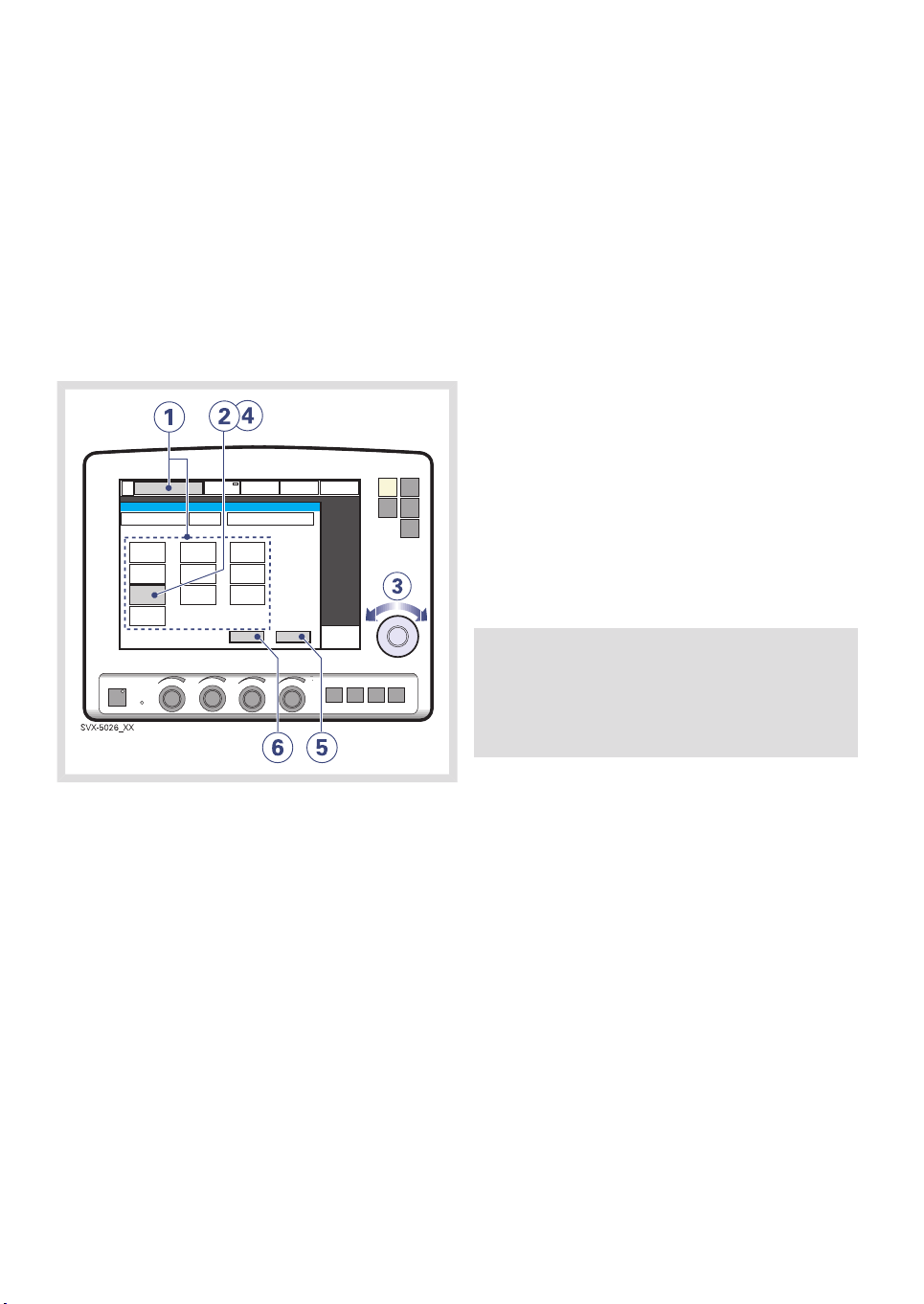
4.7 SET VENTILATION MODE
To set ventilation mode and parameters:
1. Press the Mode touchpad.
2. Press the arrow at the active Mode pad.
Available ventilation modes appear.
3. Press the touchpad for desired mode of
ventilation.
4. If Automode is selected and the patient is
triggering the ventilator, a green indicator
mark will appear.
Note: Automode is not available in NIV.
5. When a ventilation mode has been
selected, all related parameters can be
set in the same window. Calculations are
also displayed in this window.
6. Values are adjusted by turning the Main
Rotary Dial.
7. Confirm each setting by pressing the
parameter touchpad or pressing the Main
Rotary Dial.
8. To activate all settings in the window
press Accept, or to cancel the settings
press Cancel.
PROCEDURE DIAGRAM: SET VENTILATION
MODE
6
56
SVX-6032a_XX
SERVO-i VENTILATOR SYSTEM V7.0, User´s Manual
Page 57

| Operation overview |
4 |
4.8 SET ALARM LIMITS
To set alarm limits:
1. Press the Alarm Profile fixed key.
2. Press the touchpad corresponding to the
alarm limit you want to adjust or press the
Alarm sound level touchpad.
3. Turn the Main Rotary Dial to adjust values.
4. Confirm each setting by pressing the
parameter touchpad or Main Rotary Dial.
5. Press Autoset, if desired, to get a proposal
for alarm limits in VC, PC, and PRVC
modes.
Important: Before accepting Autoset
values, make sure they are appropriate
for the patient. If not, enter settings
manually.
6. Press Accept to activate the new alarm
limits.
Notes:
Autoset is not possible in Standby
because the ventilator requires patient
values in order to propose alarm limits.
Autoset is not available in supported or
NIV (optional) modes.
Current alarm limits are displayed during
ventilation in smaller figures to the right
of the parameter display.
The Main Rotary Dial becomes
inoperative for 2 seconds when a defined
safety limit for the alarm limit being
adjusted is reached. After this, it will be
operable again.
SERVO-i VENTILATOR SYSTEM V7.0, User´s Manual
57
Page 58

| Operation overview |
| 4
4.9 START VENTILATION
The Start/Standby key is used to start and
stop both invasive and non invasive ventilation.
It is also possible in Standby to start
ventilation by pressing the Start ventilation
touchpad on the screen.
WARNING! Make sure that ventilation is
started when a patient is connected to the
ventilator. When the ventilator is in Standby,
a flashing message, Patient not ventilated,
is displayed as a reminder directly above
the word Standby.
4.9.1 START INVASIVE VENTILATION
4.9.2 START NIV (NON INVASIVE
VENTILATION) (OPTION)
69; B( 1
1. When the Start/Standby key is pressed
and the SERVO-i Ventilator System is
configured for NIV, a waiting position
dialog is shown.
1. When the system is configured for
invasive ventilation press the
Start/Standby key (1) to start ventilation,
or press the Start ventilation touchpad on
the screen.
58
Note: All patient-related alarms are
turned off for 120 seconds.
2. Press the Start ventilation touchpad.
Note: Ventilation starts automatically
upon patient effort.
SERVO-i VENTILATOR SYSTEM V7.0, User´s Manual
Page 59

| Operation overview |
4 |
4.10 ADDITIONAL SETTINGS
WINDOW
To adjust breathing parameters during
ventilation, press the Additional settings
touchpad to open the Additional Settings
Window.
1. The Additional settings touchpad is in the
lower left corner of the screen.
2. Values derived from settings such as
inspiration time in seconds and calculated
inspiratory flow are displayed.
3. A white bar indicates that the selected
setting is within generally recognized
safety limits.
4. A yellow (advisory) bar indicates that the
selected setting is beyond generally
recognized safety limits (this warning is
accompanied by an audio signal and text
message).
5. A red (warning) bar indicates that the
selected setting is significantly beyond
generally recognized safety limits (this
warning is accompanied by an audio
signal and text message).
6. Turning and pressing the Main Rotary Dial
allows you to select settings and adjust
values.
7. The waveforms and measured values are
displayed. Thus, the effects of the
adjustments made can be checked
immediately.
8. The Close touchpad closes the Additional
Settings Window.
Note: The trigger sensitivity bar has
different colors based on the setting. A
green bar indicates a normal setting for
flow triggering. The risk of
self-triggering increases when the bar
is red. A white bar indicates that
pressure triggering is required.
THE ADDITIONAL SETTINGS WINDOW
Note: New settings are effective from
the first breath after adjustment (when
the touchpad is deactivated).
SERVO-i VENTILATOR SYSTEM V7.0, User´s Manual
SVX-9001
59
Page 60

| Operation overview |
| 4
4.11 SUCTIONING
4.11.1 SUCTION SUPPORT
The Suction Support function makes it
possible to automatically inhibit the ventilator
from cycling during a tracheal suction
procedure without activating alarms.
Suction Support includes:
pre-oxygenation/preparation phase
disconnect phase
post-oxygenation phase
WARNINGS!
Suction Support is not intended to be
used together with closed-suction
systems.
The minimum PEEP level during suction
support is 3 cmH2O. The ventilator will
adjust to the minimum level if the PEEP
level is below 3 cmH2O in order to detect
disconnection of the patient.
Notes:
Suction Support is not available in NIV
mode or when the O2 Breaths function is
activated.
During the disconnect phase in Suction
Support, the nebulizer is temporarily
paused.
When only one gas is connected, an
elevated oxygen level cannot be set
during the preparation phase. In this
case, the post-oxygenation phase will be
skipped.
Important: Alarms are turned off during
the disconnect phase for a maximum of 60
seconds. If the patient has not been
reconnected within 60 seconds, alarms are
activated.
60
SERVO-i VENTILATOR SYSTEM V7.0, User´s Manual
Page 61

| Operation overview |
4 |
PRE-OXYGENATION/PREPARATION
PHASE
SVX-9000 XX
To enter the pre-oxygenation/preparation
phase:
1. Press the Quick access fixed key.
2. Press the Suction Support touchpad.
3. Set the desired pre-oxygenation value by
turning the Main Rotary Dial and press
Accept.
Note: The Cancel touchpad will close the
Suction Support program.
The Check tubing alarm is turned off: the
maximum duration of the
pre-oxygenation/preparation phase is 120
seconds. After 120 seconds, the system
automatically returns to ventilation using the
previous oxygen setting.
DISCONNECT PHASE
The system automatically enters the
disconnect phase when the patient is
disconnected during the
pre-oxygenation/preparation phase.
During the disconnect phase the following
alarms are turned off for up to 60 seconds:
Apnea
Minute volume
Respiratory rate
EtCO
2
PEEP
When the patient is reconnected, the system
automatically enters the post-oxygenation
phase and restarts ventilation.
It is also possible to restart ventilation
manually by pressing the Start ventilation
touchpad.
POST-OXYGENATION PHASE
After reconnection, the ventilator will deliver
the same oxygen concentration as in the
preparation phase for 60 seconds.
After 60 seconds the system automatically
returns to ventilation using the previous
oxygen setting.
SERVO-i VENTILATOR SYSTEM V7.0, User´s Manual
61
Page 62

| Operation overview |
| 4
4.11.2 CLOSED-SUCTION SYSTEMS
If a closed-suction system is used, the Suction
Support, Insp. hold and Exp. hold functions
should not be used. Pressure-based modes
(such as Pressure Control, Pressure Support,
Bi-Vent, SIMV (PC) + PS, or NAVA) should be
used. Settings should be adjusted to levels
suitable for the patient. Hospital guidelines for
suctioning should be followed.
4.12 RE-ADJUST THE OXYGEN CELL
Note: This does not apply if the SERVO-i
Ventilator System has an O2 sensor fitted.
If the ventilator has been in continuous use for
an extended period, the measured O
concentration may drop due to normal
degradation of the oxygen cell. In order to
avoid nuisance alarms in this situation, it is
possible to temporarily adjust the O2 cell
during ventilation.
When the O2 cell adaptation function is
activated, the oxygen cell is re-adjusted so
that the current measured O2 concentration
is equal to the O2 concentration set by the
user. This temporary adjustment will be valid
until the ventilator is switched off.
2
62
Important: Before using the SERVO-i
Ventilator System, always perform a Pre-use
check to make sure the O2 cell is properly
calibrated.
SERVO-i VENTILATOR SYSTEM V7.0, User´s Manual
Page 63

| Operation overview |
4.13 DISCONNECT THE PATIENT
To disconnect and stop ventilation:
1. Physically disconnect the patient from the
ventilator.
2. Press the Start/Standby key.
3. Press Yes to stop ventilation.
4. Turn the ventilator off using the On/Off
switch behind the User Interface.
4 |
SVX-6089a_XX
To re-adjust the O2 cell:
1. Press the Menu fixed key.
2. Press the Biomed touchpad.
3. Press the O2 cell adaptation touchpad.
4. Press the Yes touchpad to perform the O
cell adaptation.
2
SERVO-i VENTILATOR SYSTEM V7.0, User´s Manual
63
Page 64

| Operation overview |
| 4
64
SERVO-i VENTILATOR SYSTEM V7.0, User´s Manual
Page 65

5 MONITOR AND RECORD
TABLE OF CONTENTS
| Monitor and record |
66|Measured values display5.1
68|Waveform display5.2
71|Show loops5.3
72|Show trends5.4
72|Show event log5.5
73|Save data5.6
5 |
SERVO-i VENTILATOR SYSTEM V7.0, User´s Manual
65
Page 66

| Monitor and record |
| 5
5.1 MEASURED VALUES DISPLAY
During ventilation, measured or calculated
values of breathing parameters are displayed.
This section describes the display, gives the
procedure for displaying additional pages of
measured and calculated values, and lists all
viewable values.
5.1.1 DESCRIPTION
20
15
10
8.5
8.5
6.5
40
6.2
8.5
6.5
30
11
6
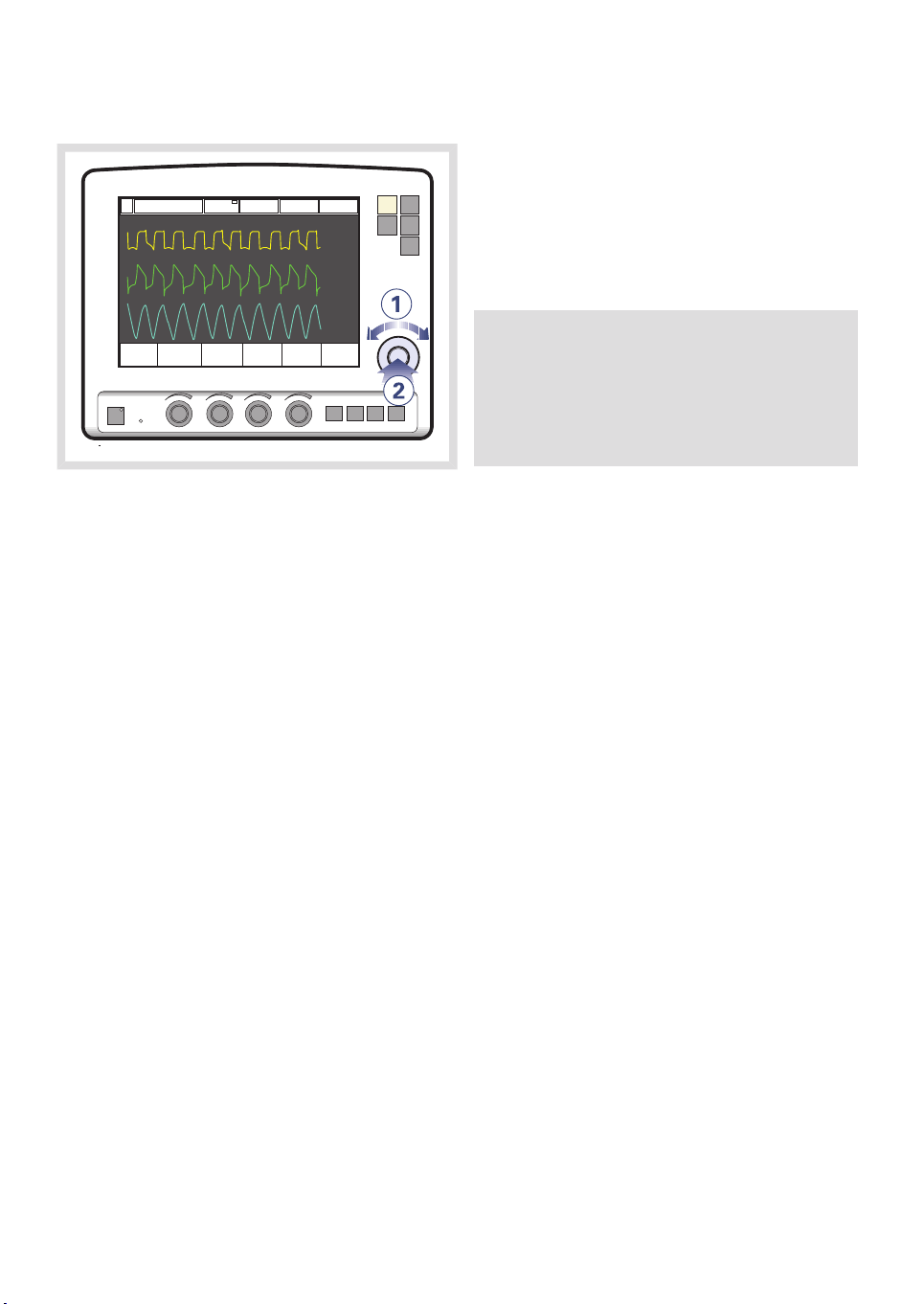
5.1.2 DISPLAY ADDITIONAL PAGES
SVX.5092_EN
To view more values:
1. Press the Additional values touchpad in
the lower right corner of the screen.
2. View desired values.
3. Press the Additional values touchpad
again to view the next page of values.
Breathing parameter values are displayed on
the right side of the screen.
1. Alarm limits are displayed in small digits.
2. An up or down arrow indicates whether
the upper or lower alarm limit has been
exceeded.
If a high priority alarm limit is exceeded,
the box turns red.
If a medium priority alarm limit is
exceeded, the box turns yellow.
3. Off-scale values are indicated by ***.
4. It is possible to change which values are
displayed in the measured value boxes.
(See Configuration chapter)
66
Notes:
In NIV mode there is only one page of
additional values.
In Nasal CPAP mode no additional values
are available.
SERVO-i VENTILATOR SYSTEM V7.0, User´s Manual
Page 67

5.1.3 VALUES LIST
Values in boldface are shown on the first page
by default.
| Monitor and record |
5 |
Ppeak
Pmean
PEEP
tot
RR
O
2
I:E
Ti/Ttot
MVe
MVe sp / MVe
VTi
VTe
ee
etCO
2
CO
2
VTCO
2
Maximum inspiratory pressure
Pressure during end-inspiratory pausePplat
Mean airway pressure
Positive end expiratory pressure
Set PEEP + Intrinsic PEEPPEEP
Continuous Positive Airway Pressure (Nasal CPAP only)CPAP
Respiratory Rate
Measured oxygen concentration in vol.%
Inspiration timeTi
Time constantTc
Inspiration to expiration ratio (during controlled ventilation)
Duty cycle or ratio of inspiration time to total breathing cycle time (during
spontaneous breathing and Bi-Vent).
Expiratory Minute Volume
Inspiratory Minute VolumeMVi
Spontaneous expiratory minute volume (Bi-Vent)MVe sp
The relation between spontaneous expired minute volume and total expired
minute volume (Bi-Vent).
Leakage % (NIV)Leakage
Inspiratory Tidal Volume
Expiratory Tidal Volume
End expiratory flow
End tidal carbon dioxide concentration (CO
Analyzer - option)
2
Volume of expired CO2 per minute (CO2 Analyzer - option)
CO2 tidal elimination (CO2 Analyzer - option)
Dynamic characteristicsCdyn
Stress IndexSI
Static compliance, respiratory systemCstatic
ElastanceE
Inspiratory resistanceRi
Expiratory resistanceRe
Work of breathing, ventilatorWOB v
Work of breathing, patientWOB p
SERVO-i VENTILATOR SYSTEM V7.0, User´s Manual
67
Page 68

| Monitor and record |
| 5
Indicator for respiratory driveP0.1
Shallow Breathing IndexSBI
5.2 WAVEFORM DISPLAY
The following color-coded waveforms are
shown on the user interface screen by default:
pressure time
flow time
volume time
If the optional Edi module and CO2 Analyzer
are connected, the following color-coded
waveforms are shown:
pressure time
flow time
Edi time
CO2 concentration time
5.2.1 DESCRIPTION
The default waveform display has the following
characteristics:
The value of a measured parameter vs. time
is displayed.
The displayed parameter and the scale are
indicated on the y-axis.
The pressure vs. time display is dark yellow.
The flow vs. time display is green.
The volume vs. time display is light blue.
The Edi signal vs. time display is light green.
The CO2 concentration vs. time display is
light yellow.
This section describes the waveform display,
and the procedures for hiding/displaying the
volume, Edi and CO2 waveforms and for
adjusting the sweep speed and scale of the
waveforms.
68
SERVO-i VENTILATOR SYSTEM V7.0, User´s Manual
Page 69

| Monitor and record |
5 |
5.2.2 SHOW AND HIDE
Notes:
The pressure waveform and the flow
waveform are always displayed. The
volume, Edi and CO2 waveforms may be
hidden. Thus, 2, 3, or 4 waveforms may
be displayed.
When you hide a waveform, the
remaining waveforms are expanded to
use all available screen space.
SVX-6029a_XX
To show or hide the volume, Edi or the CO
2
waveform display:
1. Press the Quick access fixed key.
2. Press the Waveform configuration
touchpad.
3. Press the touchpad corresponding to the
waveform you wish to show or hide.
SERVO-i VENTILATOR SYSTEM V7.0, User´s Manual
69
Page 70

| Monitor and record |
| 5
5.2.3 ADJUST SCALE/SWEEP SPEED
To set the sweep speed and amplitude for
displayed waveforms:
1. Press the Quick access fixed key.
2. Press the Waveform Scales touchpad.
3. Press the touchpad corresponding to the
waveform whose scale you wish to
change or select a sweep speed (5, 10 or
20 mm/s).
4. To adjust the scale of a waveform, turn
the Main Rotary Dial to the desired value
or use auto scale (press Auto).
Important: MAQUET does not recommend
using auto scale in Bi-Vent mode, when
patient breathing is spontaneous on both
levels.
70
SVX-6008a_XX
SERVO-i VENTILATOR SYSTEM V7.0, User´s Manual
Page 71

| Monitor and record |
5 |
5.3 SHOW LOOPS
The Loops function provides a graphical
representation of the relationship between
flow-volume and pressure-volume.
To activate the Loops function:
1. Press the Quick access fixed key.
2. Press the Loops touchpad
3. Press
[reference loop] to store a
reference loop.
4. Press [overlay loops] to see the two
previous loops simultaneously.
5. To close the window, press Close.
SVX-6004a_XX
SERVO-i VENTILATOR SYSTEM V7.0, User´s Manual
71
Page 72

| Monitor and record |
| 5
5.4 SHOW TRENDS
Trend values are stored every 60 seconds and
retained as far back as 24 hours. Stored
events and system changes are shown as
event stamps.
8. If a recording is saved at a time
corresponding to the cursor position, a
recording button is shown. To view the
recording, press the button.
5.5 SHOW EVENT LOG
To show trends:
1. Press the Trends fixed key.
2. Use the up and down arrows to scroll
between the different trend channels.
3. To quit the Trends Window press Close.
4. To adjust the time resolution press the
Hours touchpad and turn the Main Rotary
Dial.
5. Activate the Cursor. Move it back and
forth on the time axis using the Main
Rotary Dial or touch screen.
6. Time valid for the cursor position. For
event stamps, an explanation appears.
7. Logged event stamps.
72
To view the Event Log:
1. Press the Menu fixed key.
2. Press the Review touchpad.
3. Press the Event log touchpad to view all
logged events.
4. Use the arrows to scroll.
SERVO-i VENTILATOR SYSTEM V7.0, User´s Manual
Page 73

| Monitor and record |
5 |
5.6 SAVE DATA
Waveforms and settings may be saved in the
following ways:
A 20-second recording may be taken for
immediate on-screen analysis.
Screen data or patient data may be written
to an Ventilation Record Card (option) for
later analysis (patient data file is readable
by Microsoft Excel).
5.6.1 RECORD WAVEFORMS
1. Press the Save fixed key.
To save one recording of the current waveform
along with breathing parameter values:
A total of 20 seconds of data will be recorded:
10 seconds before the Save key was pressed
and 10 seconds after the Save key was
pressed.
SERVO-i VENTILATOR SYSTEM V7.0, User´s Manual
Note: If Save is pressed again, the previous
recording will be erased. Using Admit
patient also erases the previous recording.
73
Page 74

| Monitor and record |
| 5
5.6.2 VIEW RECORDED WAVEFORMS.
SVX-5093a_XX
To view the data in a recorded waveform:
1. Press the Menu fixed key.
2. Press the Review touchpad.
3. Press the Recorded waveform touchpad.
4. Vertical gray lines indicate the time when
the Save key was pressed.
5. Press the Settings touchpad to open the
list of parameter settings in use at the time
the Save key was activated.
6. Press the Cursor touchpad to activate the
cursor. Move the cursor using the Main
Rotary Dial.
7. View measured/calculated values next to
the vertical gray lines.
8. Press Close to quit the Recorded
Waveform Window.
74
SERVO-i VENTILATOR SYSTEM V7.0, User´s Manual
Page 75

5.6.3 VENTILATION RECORD CARD (OPTION)
The Ventilation Record Card (VRC) can be
used in Standby or during ventilation. The
following data can be saved for analysis:
screen data
patient data
Important: Always handle the VRC and its
contents in accordance with regulations
and hospital routines.
Please refer to the Ventilation Record Card
User's Manual.
Copy Screen Data to a Ventilation Record
Card
To make a copy of the screen, the Save key
must be configured. It is possible to copy
multiple data sets to the same Ventilation
Record Card.
| Monitor and record |
SVX-9007_XX
1. Press the Menu fixed key.
2. Press the Copy touchpad.
3. Press the Copy screen touchpad.
4. Insert the VCR and press OK to continue.
5. Press the Save fixed key.
5 |
SERVO-i VENTILATOR SYSTEM V7.0, User´s Manual
A copy of the screen is stored on the VRC.
Notes:
To make another screen copy, press the
Save key again.
When the VRC is removed or the
ventilator is restarted, the Save key is
automatically reconfigured to save a
recording.
75
Page 76

| Monitor and record |
| 5
Copy Patient Data to a Ventilation Record
Card
The following patient data may be copied to
a VRC:
Event log
Trends
Recordings
Open Lung Tool® data
Neuro Ventilatory Tool data
Included in all data files are:
Patient name and ID
Ventilator serial number
Pre-use check status.
To copy patient data to a VRC:
1. Press the Menu fixed key.
2. Press the Copy touchpad.
3. Press the Copy data touchpad.
4. Insert the VRC.
5. Press the Copy data touchpad.
Remove the VRC when copying is complete.
76
SERVO-i VENTILATOR SYSTEM V7.0, User´s Manual
Page 77

| Ventilation, modes and functions |
6 VENTILATION, MODES AND FUNCTIONS
TABLE OF CONTENTS
6 |
78|Introduction6.1
80|Important definitions6.2
82|Settings6.3
88|Volume Control6.4
93|Pressure Control6.5
96|Pressure Regulated Volume Control6.6
99|Volume Support6.7
102|Pressure Support6.8
105|Spontaneous/CPAP6.9
107|Automode6.10
111|SIMV6.11
120|Bi-Vent6.12
123|Non Invasive Ventilation6.13
127|Nasal CPAP (Infant only)6.14
129|Backup ventilation6.15
133|Ventilatory parameters - overview6.16
136|Special functions6.17
139|Open Lung Tool6.18
142|Stress Index6.19
145|Heliox6.20
SERVO-i VENTILATOR SYSTEM V7.0, User´s Manual
77
Page 78

| Ventilation, modes and functions |
| 6
6.1 INTRODUCTION
The SERVO-i Ventilator System can operate
in several different modes. This chapter
describes the modes, their settings, and
associated safety information.
It also summarizes special ventilatory
functions, backup ventilation, and breathing
parameters.
See the Technical data chapter for default
values and allowed ranges for the breathing
parameters.
Note:
The SERVO-i Ventilator System is delivered
preset with the following configuration
options:
Breathing parameters are based on either
Minute Volume or Tidal Volume.
Breathing parameters are based on either
I:E Ratio or Inspiration Time.
6.1.1 WARNINGS
The following warnings apply to Non
Invasive Ventilation (NIV) only:
- Avoid high inspiratory pressure as it
may lead to gastric overdistention and
risk of aspiration. It may also cause
excessive leakage.
- Use of the Nebulizer is not
recommended.
- We recommend
ventilator-independent monitoring for
Nasal CPAP.
Ensure that PRVC, SIMV (PRVC) and VS
function properly (especially for small
patients):
- Avoid leakage (e.g. due to an uncuffed
endotracheal tube).
- If compliance compensation is used,
make sure that the compressible
volume of the patient circuit is not
changed after the Pre-use check /
Patient Circuit Test has been
performed (e.g. filling an active
humidifier with water after the test has
been made).
Note: Not all warnings apply to all modes.
WARNINGS!
Be sure to set alarm limits as appropriate
for each mode, especially:
- Minute Volume Alarm
- Apnea time
Self-triggering should be avoided. Do not
set the trigger sensitivity too high.
To protect the patient’s lungs from
excessive pressure it is important to set
the upper pressure limit to a suitable
value.
78
SERVO-i VENTILATOR SYSTEM V7.0, User´s Manual
Page 79

| Ventilation, modes and functions |
6 |
6.1.2 APPLICATION
The SERVO-i Ventilator System also contains
tools to assist the user in application of lung
protective methodologies.
6.1.3 SCOPE - VENTILATORY NEEDS
When required, all ventilation is provided for
mandatorily. When the patient is able to initiate
a breath, the ventilator supports and monitors
the patient´s breathing capability and controls
ventilation only if required.
The ventilator can be used for:
1. controlled ventilation
2. supported ventilation, or
3. spontaneous breathing/CPAP
It also allows for combined ventilatory control
or support. Spontaneous breathing efforts are
sensed during controlled ventilation, e.g.
Volume Control. Mandatory ventilation can be
used during supported/spontaneous
breathing, e.g. the enhanced SIMV
functionality.
The Automode functionality continuously
adapts to the patient´s breathing capability.
SERVO-i VENTILATOR SYSTEM V7.0, User´s Manual
79
Page 80

V
V
| Ventilation, modes and functions |
| 6
6.2 IMPORTANT DEFINITIONS
The graphic display of pressure, flow and
volume is visualized in waveforms. Modes of
ventilation directly affect flow, pressure and
volume patterns.
6.2.1 VOLUME CONTROL
xy z
P
2
4
3
1
5
7
8
14
6
t
11
t
10
9
FLOW-TIME WAVEFORM
7. Peak inspiratory flow
8. Zero flow phase
9. Peak expiratory flow
10. Slope decelerating expiratory limb
11. End expiratory flow
VOLUME-TIME WAVEFORM
12. Start of inspiration
13. The slope represents current delivery of
inspiratory tidal volume
14. End inspiration
15. The slope represents current patient
delivery of expiratory tidal volume
16. End expiration
13
12
I:E
15
16
t
X. Inspiration time
Y. Pause time
Z. Expiration time
PRESSURE-TIME WAVEFORM
1. Start of Inspiration
2. Peak inspiratory pressure
3. Early inspiratory pause pressure
4. End inspiratory pause pressure
5. Early expiratory pressure
6. End expiratory pressure
80
SERVO-i VENTILATOR SYSTEM V7.0, User´s Manual
Page 81

V
| Ventilation, modes and functions |
6 |
6.2.2 PRESSURE CONTROL
I:E
Z
1
4
8
X
P
V
X. Inspiration time
Z. Expiration time
PRESSURE-TIME WAVEFORM
VOLUME-TIME WAVEFORM
8. Start of inspiration
2
3
5
6
9
7
10
9. End inspiration
10. End expiration
t
t
t
1. Start of Inspiration
2. Peak inspiratory pressure
3. End expiratory pressure
FLOW-TIME WAVEFORM
4. Peak inspiratory flow
5. End inspiratory flow
6. Peak expiratory flow
7. End expiratory flow
SERVO-i VENTILATOR SYSTEM V7.0, User´s Manual
81
Page 82

| Ventilation, modes and functions |
| 6
6.3 SETTINGS
6.3.1 TRIGGER FUNCTIONALITY
Trigger sensitivity determines the level of
patient effort needed to trigger the ventilator
to inspiration.
Trigger sensitivity can be set as flow triggering
(settings above zero) or pressure triggering
(settings below zero). Normally flow triggering
is preferable as this enables the patient to
breathe with less effort.
The sensitivity is set as high as possible
without self-triggering. This ensures that
triggering is patient initiated and avoids
auto-cycling by the ventilator.
Important: In NIV it is not possible to set
trigger sensitivity.
Trigg. Pressure Trigg. Flow
-20 10
WHITE GREEN RED
06
WARNINGS!
WARNING! The trigger sensitivity bar
has different colors based on the
setting. A green bar indicates a normal
setting for flow triggering. The risk of
self-triggering increases when the bar
is red. A white bar indicates pressure
triggering.
WARNING! If the trigger sensitivity is
set too high, a self triggering
(auto-triggering) condition may be
reached. This condition can also be
reached if there is leakage in the
breathing system, e.g. if an uncuffed
endotracheal tube is used. Triggering
will then be initiated by the system and
not by the patient. This should always
be avoided by decreasing the trigger
sensitivity.
During expiration, the ventilator continuously
delivers a gas flow (bias flow), which is
measured in the expiratory channel. For details
of the bias flow, see Technical data on
page 226.
82
SERVO-i VENTILATOR SYSTEM V7.0, User´s Manual
Page 83

| Ventilation, modes and functions |
6 |
At a trigger sensitivity level above zero (0), The
ventilator senses deviations in the bias flow
delivered during expiration. These deviations
are caused by the inspiratory efforts of the
patient. The further to the right on the scale,
the more sensitive is the trigger function.
At a trigger sensitivity level below zero (0), the
ventilator senses deviations in the pressure
below PEEP created by the patient. The
pressure below PEEP required to initiate a
breath is shown when the setting is made. The
further to the left on the scale, the more effort
is required to trigger.
6.3.2 INSPIRATORY RISE TIME
100 %
t
Time to peak inspiratory flow or pressure at
the start of each breath as a percentage of the
respiratory cycle time or in seconds. Increased
rise time will affect the rate of flow/pressure
increase and can be evaluated by the shape
of the flow and pressure waveforms.
SERVO-i VENTILATOR SYSTEM V7.0, User´s Manual
Inspiratory rise time (%) is applicable in
Pressure Control, Volume Control, PRVC,
SIMV-Volume Control, SIMV-Pressure Control,
SIMV-PRVC. Setting can be in the range
0-20% of the respiratory cycle time.
83
Page 84

| Ventilation, modes and functions |
| 6
Inspiratory rise time set in seconds is
applicable in Pressure Support, Volume
Support and Bi-Vent. For adults the range is
0-0.4 seconds and for infants the range is
0-0.2 seconds.
Note: When the ventilator is configured for
setting of Inspiration time, the unit for
Inspiratory rise time then automatically
switches to seconds for all ventilation
modes.
Normally in supported modes the Inspiratory
rise time should be increased from the default
setting and to give more comfort to the
patient.
6.3.3 TRIGGER TIMEOUT
Trigger Timeout is the maximum allowed
apnea time in Automode before controlled
ventilation is activated.
Initially the ventilator adapts with a dynamic
Trigger Timeout limit. This means that for the
spontaneously triggering patient the timeout
increases successively during the first ten
breaths.
For Automode trigger timeout setting ranges,
see section 230 on page 230.
6.3.4 PEEP
PEEP
SVX-646_EN
A Positive End Expiratory Pressure is
maintained in the alveoli and may prevent the
collapse of the airways.
For Positive End Expiratory Pressure setting
ranges, see section 230 on page 231
6.3.5 I:E RATIO / INSPIRATION TIME
The setting of breathing parameters in
SERVO-i Ventilator System can be configured
in two different ways, based on:
I:E ratio (independent of changes of e.g. the
breathing frequency) or,
Inspiration time in seconds (independent of
changes of e.g. the breathing frequency),
to better meet the requirements for infant
care.
When the ventilator is configured for setting
of Inspiration time, the unit for Pause time and
Insp. rise time then automatically switches to
seconds. The resulting I:E ratio for each setting
is shown in the upper right information area
of the ventilation mode window.
84
As the inspiration time is explicitly set, a
change of for example the Respiratory Rate
will affect the I:E ratio. As a safety precaution,
it will therefore be indicated when the resulting
I:E ratio passes 1:1 in either direction.
SERVO-i VENTILATOR SYSTEM V7.0, User´s Manual
Page 85

| Ventilation, modes and functions |
6 |
Note: The touchpad Breath cycle time is
not shown when an SIMV mode is selected,
since there is no need to set Breath cycle
time when Inspiration time is directly set.
6.3.6 INSPIRATORY CYCLE-OFF
SVX-205_XX
Inspiratory Cycle-off is the point at which
inspiration changes to expiration in
spontaneous and supported modes of
ventilation. A decrease of the inspiratory flow
to a preset level causes the ventilator to switch
to expiration. This preset level is measured as
a percentage of the maximum flow during
inspiration.
For inspiratory cycle off setting ranges, see
section 230 on page 230.
SERVO-i VENTILATOR SYSTEM V7.0, User´s Manual
85
Page 86

| Ventilation, modes and functions |
| 6
6.3.7 BREATH CYCLE TIME
This is the length of the breath i.e. the total
cycle time of the mandatory breath in SIMV
(inspiration, pause plus expiration).
Note: The touchpad Breath cycle time is
not shown when an SIMV mode is selected
and inspiration time is configured. Refer to
heading I:E ratio / Inspiration times.
6.3.9 CONTROLLED / SUPPORTED
PRESSURE LEVEL
PC (Pressure Control level) above PEEP is the
set inspiratory pressure level for each
mandatory breath in Pressure Control and
SIMV (PC) + PS, and also for backup
ventilation in Pressure Support and NAVA.
PS (Pressure Support level) above PEEP is the
set inspiratory pressure support level for
triggered breaths in Pressure Support, SIMV
modes and Bi-Vent.
6.3.10 O2 CONCENTRATION
The setting range for the gas mixer is 21% O
to 100% O2. The alarm limits are automatically
set at approximately 5% O2 above or below
the set concentration value. The alarm is
delayed 40 seconds after changing the O
2
concentration setting. There is also an
absolute minimum alarm limit of 18% O2 which
is independent of operating settings.
2
6.3.8 VOLUME SETTING
Depending on the ventilator configuration the
inspiratory volume can be set as:
Minute Volume or,
Tidal Volume
86
SERVO-i VENTILATOR SYSTEM V7.0, User´s Manual
Page 87

6.3.11 RESPIRATORY RATE / SIMV RATE
Respiratory rate is the number of controlled
mandatory breaths per minute in controlled
modes excluding SIMV. The respiratory rate
is also used for calculation of tidal volume if
the ventilator is configured for Minute volume
setting. SIMV rate is the number of controlled
mandatory breaths in SIMV modes.
6.3.12 PREVIOUS MODE
3
1. Time when previous mode was
inactivated.
2. Name of the previous mode.
3. Press the touchpad Show previous mode
to recall the previous accepted ventilation
mode.
2
| Ventilation, modes and functions |
4
4. Activate the previous used ventilation
mode settings by pressing the Accept
touchpad.
Notes:
The previous mode function is not
available after a Pre-use check, changing
of patient category, admitting a new
patient, use of the same ventilation mode
for more than 24 hours or after restarting
the system.
When Previous Mode is activated during
Backup ventilation, the ventilator returns
to the mode that was active before
Support mode was initiated.
A recall of previous settings is only
possible after a change of ventilation
mode.
6 |
SERVO-i VENTILATOR SYSTEM V7.0, User´s Manual
87
Page 88

| Ventilation, modes and functions |
| 6
6.4 VOLUME CONTROL
6.4.1 FUNCTIONAL DESCRIPTION VOLUME CONTROL
In the flow/volume oriented modes a controlled
flow is used to maintain the set inspiratory
Tidal Volume.
Volume Controlled ventilation ensures that the
patient receives a certain pre-set Minute/Tidal
Volume.
The SERVO-i Ventilator System can be
configured to set Tidal Volume or Minute
Volume. The following parameters are set:
1. Tidal Volume (ml) or the Minute Volume
(l/min)
2. Respiratory Rate (b/min)
3. PEEP (cmH2O)
4. Oxygen concentration (%)
5. I:E ratio / Insp. time
6. Pause time (%/s)
7. Inspiratory rise time (%/s)
8. Trigg. Flow / Trigg. Pressure
The airway pressure is dependent on the tidal
volume, inspiration time and the resistance
and compliance of the respiratory system. The
set tidal volume will always be delivered. An
increase in the resistance and decrease in
compliance will lead to an increased airway
pressure. To protect the patient's lungs from
excessive pressure, it is very important to set
the upper pressure limit to a suitable value.
6.4.2 FLOW ADAPTATION
It is possible for the patient to trigger extra
breaths if they can overcome the pre-set
trigger sensitivity. It is also possible for the
patient, by their own inspiratory efforts, to
receive a higher inspiratory flow and Tidal
Volume during an inspiration than pre-set. The
flow during inspiration is constant. The patient
can trigger extra breaths.
88
SERVO-i VENTILATOR SYSTEM V7.0, User´s Manual
Page 89

| Ventilation, modes and functions |
6 |
Volume Controlled ventilation has, by tradition,
delivered each breath with a constant flow and
constant inspiratory and expiratory times,
according to the settings. The SERVO-i
Ventilator System gives the possibility to the
patient to modify both flow rate and timing.
So, if a pressure drop of 3 cmH
O is detected
2
during inspiration, the ventilator cycles to
Pressure Support with a resulting increase in
inspiratory flow. When the flow decreases to
the calculated target level this flow will be
maintained until the set Tidal Volume is
delivered.
The illustrated waveform show some practical
consequences of this enhanced functionality.
the top waveform shows the trace for a
normal Volume Controlled breath
the second waveform shows a situation
when inspiration is prematurely interrupted
as the set tidal volume has been delivered
the third waveform shows a situation where
the patient maintains a flow rate higher than
the calculated target value. The set Tidal
Volume has been delivered when calculated
target flow is reached and the inspiration is
prematurely interrupted
the bottom waveform, shows a situation
where the increased flow rate is maintained
into the expiratory period. The patient will
receive a higher tidal volume than set due
to a higher flow/volume demand than
calculated.
SERVO-i VENTILATOR SYSTEM V7.0, User´s Manual
89
Page 90

| Ventilation, modes and functions |
| 6
6.4.3 VOLUME CONTROL IN DETAIL
SVX-9002_XX
1. Volume Control assures a preset tidal
volume with constant flow during a preset
inspiratory time at a preset frequency.
2. The inspiratory flow is constant and
depends on User Interface setting.
3. Inspiration starts according to the preset
frequency or when the patient triggers.
4. If the patient makes an inspiratory effort
during the inspiratory period, the ventilator
will switch to Pressure Support to satisfy
the patient´s flow demand.
1 2
3
4
Expiration starts:
a. When the preset tidal volume is delivered
and after the preset pause time.
b. When the flow returns to the set value after
the preset tidal volume is delivered and
after the preset pause time (on-demand
support). The patient is however always
guaranteed an expiration time
corresponding to at least 20% of the total
breath.
c. If the upper pressure limit is exceeded.
90
SERVO-i VENTILATOR SYSTEM V7.0, User´s Manual
Page 91

| Ventilation, modes and functions |
6 |
6.4.4 VOLUME CONTROL WITH
ALTERNATIVE FLOW PATTERNS
When the Volume Control with alternative flow patterns is enabled in the start-up
configuration, new touchpads for setting of
alternative flow patterns are available in
Volume Control, Automode VC <--> VS and
SIMV (VC)+PS.
2
1 3
4
To ventilate with Volume Control with flow
adaptation:
Press the Volume Control with flow
adaptation touchpad.
Press Accept.
Volume Control without flow adaptation
The ventilator delivers volume strictly
according to the settings.
To ventilate with Volume Control without flow
adaptation:
Press the Volume control without flow
adaptation touchpad.
Press Accept.
Note: Set trigger sensitivity at an adequate
level. A patient who needs more ventilation
may increase the breathing frequency
instead of increasing the flow during
inspiration.
1. Volume control with flow adaptation
2. Volume control without flow adaptation
3. Volume control with decelerating flow
4. Flow pattern
See section User Interface Symbols on
page 21.
Volume Control with flow adaptation
The ventilator interacts with the patient and
delivers the extra volume requested regardless
of the settings. See section Flow adaptation
on page 88.
SERVO-i VENTILATOR SYSTEM V7.0, User´s Manual
Volume Control with decelerating flow
The ventilator delivers a decelerating flow
according to Flow pattern settings.
To ventilate with decelerating flow:
Press the Volume control with decelerating
flow touchpad.
Press the Flow pattern touchpad and set
the flow pattern with the Main Rotary Dial.
The flow pattern can be set so that the end
inspiratory flow is 75 %, 50 % (default),
25 % or 0 % of the peak flow.
Press Accept.
91
Page 92

V
| Ventilation, modes and functions |
| 6
FLOW-TIME WAVEFORM
xy z
1
2
3
4
X. Inspiration time
Y. Pause time
Z. Expiration time
1. Peak inspiratory flow
2. End inspiratory flow
3. Zero flow phase
4. Peak expiratory flow
5. Slope decelerating expiratory limb
6. End expiratory flow
STRESS INDEX
Stress index can not be calculated during
Volume control with decelerating flow. It can
only be calculated at a constant flow.
6
t
5
Notes:
Flow adaptation is not enabled in Volume
Control with decelerating flow. Set trigger
sensitivity at an adequate level. A patient
who needs more ventilation may increase
the breathing frequency instead of
increasing the flow during inspiration.
The default setting of Pause time is 0 s.
92
SERVO-i VENTILATOR SYSTEM V7.0, User´s Manual
Page 93

6.5 PRESSURE CONTROL
6.5.1 FUNCTIONAL DESCRIPTION
PRESSURE CONTROL
The Pressure Controlled mode is a controlled
breathing mode.
Breaths are delivered mandatorily at a preset
pressure level, causing a decelerating flow
pattern.
The following parameters are set:
1. PC (Pressure Control level) above PEEP
(cmH2O)
2. Respiratory Rate (b/min)
3. PEEP (cmH2O)
4. Oxygen concentration (%)
5. I:E ratio / Insp. time
6. Inspiratory rise time (%/s)
7. Trigg. Flow / Trigg. Pressure
| Ventilation, modes and functions |
The delivered volume is dependent upon the
pressure above PEEP, lung compliance and
resistance in the patient tube system and
airways. This means that the Tidal Volume can
vary. Pressure Controlled mode is preferred
when there is leakage in the breathing system
e.g. due to uncuffed endotracheal tube or in
situations when the maximum airway pressure
must be controlled. The flow during inspiration
is decelerating. The patient can trigger extra
breaths. If the patient tries to exhale during
the inspiration, the expiratory valve will allow
exhalation as long as the pressure is more
than 3 cmH2O above the set pressure level.
As the delivered tidal volume can vary it is very
important to set alarm limits for Minute Volume
to adequate levels.
6 |
SERVO-i VENTILATOR SYSTEM V7.0, User´s Manual
93
Page 94

| Ventilation, modes and functions |
| 6
6.5.2 PRESSURE CONTROL IN DETAIL
1
SVX-9003_XX
1. Pressure Control assures that the preset
inspiratory pressure level is kept constant
during the entire inspiration. Breaths are
delivered according to the preset
frequency, inspiration time and inspiratory
pressure level resulting in a decelerating
flow.
2. The preset pressure level is controlled by
the ventilator. The resulting volume
depends on the set pressure level,
inspiration time and the patient´s lung
mechanical properties during each breath
with a decelerating flow.
3. Inspiration starts according to the preset
frequency or when the patient triggers.
2 3
Expiration starts:
a. After the termination of preset inspiration
time.
b. If the upper pressure limit is exceeded.
94
SERVO-i VENTILATOR SYSTEM V7.0, User´s Manual
Page 95

ACTIVE EXPIRATORY VALVE
t
SVX-9008_XX
If a patient tries to exhale during the
inspiration, pressure increases. When it
increases 3 cmH2O above the set inspiratory
pressure level, the expiratory valve opens and
regulates the pressure down to the set
inspiratory pressure level.
| Ventilation, modes and functions |
6 |
Upper pressure
Limit
t
SVX-9009_EN
If the pressure increases to the set upper
pressure limit e.g. the patient is coughing, the
expiratory valve opens and the ventilator
switches to expiration.
SERVO-i VENTILATOR SYSTEM V7.0, User´s Manual
95
Page 96

| Ventilation, modes and functions |
| 6
6.6 PRESSURE REGULATED VOLUME CONTROL
6.6.1 FUNCTIONAL DESCRIPTION PRVC
The Pressure Regulated Volume Control
(PRVC) mode is a controlled breathing mode.
Breaths are delivered mandatorily to assure
preset volumes, with a constant inspiratory
pressure continuously adapting to the patient´s
condition. The flow pattern is decelerating.
The ventilator delivers a pre-set Tidal Volume.
The pressure is automatically regulated to
deliver the pre-set volume but limited to
5 cmH2O below the set upper pressure limit.
The SERVO-i Ventilator System can be
configured to set Tidal Volume or Minute
Volume. The following parameters are set:
1. Tidal Volume (ml) or Minute Volume (l/min)
2. Respiratory Rate (b/min)
3. PEEP (cmH2O)
4. Oxygen concentration (%)
5. I:E ratio / Insp. time
6. Inspiratory rise time (%/s)
7. Trigg. Flow / Trigg. Pressure
The flow during inspiration is decelerating. The
patient can trigger extra breaths.
96
SERVO-i VENTILATOR SYSTEM V7.0, User´s Manual
Page 97

6.6.2 PRVC IN DETAIL
| Ventilation, modes and functions |
6 |
1
SVX-9006_XX
1. PRVC assures a set target minute
ventilation to the patient. The target
volume is based upon settings for Tidal
Volume, frequency and inspiration time.
2. The inspiratory pressure level is constant
during each breath, but automatically
adapts in small increments
breath-by-breath to match the patient´s
lung mechanical properties for target
volume delivery.
3. Inspiration starts according to a preset
frequency or when the patient triggers.
2
3
Expiration starts:
a. After the termination of preset inspiration
time
b. If the upper pressure limit is exceeded.
SERVO-i VENTILATOR SYSTEM V7.0, User´s Manual
97
Page 98

| Ventilation, modes and functions |
| 6
The first breath of a start sequence is a
volume-controlled test breath with Pause time
set to 10%. The measured pause pressure of
this breath is then used as the pressure level
for the following breath. An alarm is activated
if the pressure level required to achieve the
set target volume cannot be delivered due to
a lower setting of the Upper pressure limit
(- 5 cmH2O).
98
SERVO-i VENTILATOR SYSTEM V7.0, User´s Manual
Page 99

6.7 VOLUME SUPPORT
6.7.1 FUNCTIONAL DESCRIPTION VOLUME
SUPPORT
A patient-adapted constant inspiratory support
is supplied when activated by patient effort.
The resulting volume is continuously
monitored and the constant inspiratory
pressure automatically adjusts to the required
level. The patient determines frequency and
duration of the breaths which show a
decelerating flow pattern.
The Volume Support mode is a patient initiated
breathing mode, where the patient will be
given support in proportion to their inspiratory
effort and the target Tidal Volume.
4
1
2
3
7
5
8
6
9
| Ventilation, modes and functions |
8. Resp.Rate (b/min) in backup ventilation.
9. I:E / Ti (s) in backup ventilation (depending
on configuration).
If the patient’s activity increases the inspiratory
pressure support will decrease provided the
set Tidal Volume is maintained. If the patient
breathes below the set Tidal Volume the
inspiratory pressure support will increase.
6 |
The following parameters are set:
1. Tidal Volume (ml)
2. PEEP (cmH2O)
3. Oxygen concentration (%)
4. Inspiratory rise time (s)
5. Trigg. Flow / Trigg. Pressure
6. Inspiratory Cycle off (%)
7. Tidal Volume (ml)
SERVO-i VENTILATOR SYSTEM V7.0, User´s Manual
99
Page 100

| Ventilation, modes and functions |
| 6
SVX-657_EN
The start breath is given with 10 cmH2O
support. From that breath the ventilator
calculates and continuously regulates the
pressure needed to deliver the pre-set Tidal
Volume.
During the next 3 breaths of the start up
sequence the maximum pressure increase is
20 cmH2O for each breath. After the start up
sequence the pressure increases or decreases
in steps of maximum 3 cmH2O.
If the delivered Tidal Volume decreases below
the set Tidal Volume the pressure support level
is increased in steps of maximum 3 cmH2O
until preset Tidal Volume is delivered. If the
pressure support level causes a larger Tidal
Volume than preset, the support pressure is
lowered in steps of maximum 3 cmH2O until
the preset Tidal Volume is delivered.
For maximum inspiration time, see section
Functions in ventilation modes on page 235.
An alarm is activated if the pressure level
required to achieve the set target volume
cannot be delivered due to a lower setting of
the upper pressure limit - 5 cmH2O.
In this mode it is also important to set the
apnea time appropriate to the individual
patient situation. If this time is reached then
the ventilator will automatically switch to
backup ventilation. In all spontaneous modes
it is important to set the Minute Volume alarm.
100
SERVO-i VENTILATOR SYSTEM V7.0, User´s Manual
 Loading...