

Page 1
x
User's Manual
SERVO-air Ventilator System v2.1
Page 2

Page 3

TABLE OF CONTENTS
| TABLE OF CONTENTS |
1
2
3
4
5
6
7
8
9
10
5|Introduction
15|System Overview
37|Operation overview
45|Displaying and saving data
55|Ventilation modes
83|Ventilatory settings and functions
109|Alarm handling
123|Service & Settings
131|Technical data
159|Index
SERVO-airVentilator System v2.1, User's Manual
Infologic 1.39
3
Page 4

| TABLE OF CONTENTS |
4
SERVO-airVentilator System v2.1, User's Manual
Infologic 1.39
Page 5

1 Introduction Table of contents
| Introduction |
6|Device description1.1
8|Safety guidelines1.2
14|Version and configurations1.3
1 |
SERVO-airVentilator System v2.1, User's Manual
5
Page 6
| Introduction |
| 1
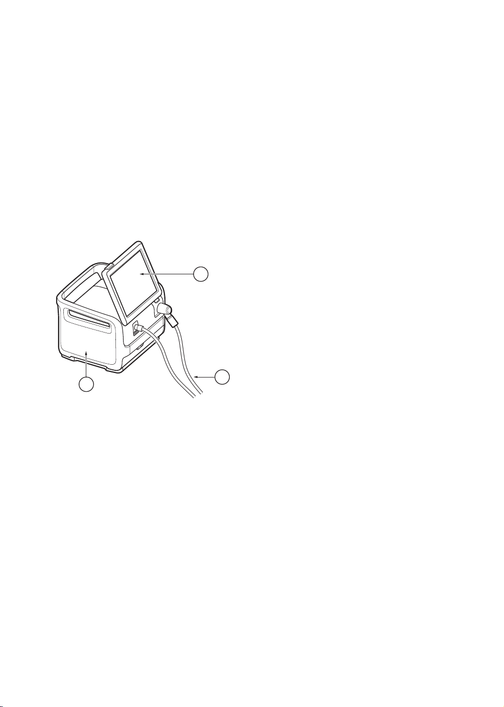
1.1 Device description
1.1.1 Device components
The ventilator system consists of:
1. a user interface for setting ventilation
modes, displaying data and indicating
alarms
2. a patient unit for mixing gases and
controlling gas delivery
3. a patient circuit for delivering and
exchanging gases
1
1.1.2 Intended use
The SERVO-air ventilator system is:
• intended for respiratory support, monitoring
and treatment of pediatric and adult
patients
• to be used only by healthcare providers
• to be used only in professional healthcare
facilities and for transport within these
facilities
2
6
3
SERVO-airVentilator System v2.1, User's Manual
Page 7

| Introduction |
1 |
1.1.3 User's Manual
This manual summarizes the functions and
safety features of the ventilator system. It is
not all-inclusive and should not be seen as a
substitute for training.
1.1.4 Cleaning & Maintenance
Please refer to the SERVO-air Cleaning and
Maintenance User's Manual.
1.1.5 Servicing Guidelines
CAUTIONS:
• Regular service: The ventilator system
must be serviced at regular intervals by
Maquet authorized personnel who have
received specialized training.
• Complete service records: All service
performed on the ventilator system must
be recorded in a service log in
accordance with hospital procedures and
local and national regulations.
1.1.6 Disclaimers
Non-professional servicing:
Maquet has no responsibility for the safe
operation of the ventilator system if
installation, service or repairs are performed
by persons other than Maquet authorized
personnel.
• Service contract: It is strongly
recommended that all service on the
ventilator system should be performed
as part of a service contract with Maquet.
Note: If the ventilator system is to be a part
of another system it requires an evaluation
of the requirements of the IEC 60601-1
standard.
SERVO-airVentilator System v2.1, User's Manual
7
Page 8

| Introduction |
| 1
1.2 Safety guidelines
Follow these safety guidelines. Additional
warnings appear in context throughout this
document.
Information is highlighted with Warning,
Caution, Important or Note, where:
WARNING! Indicates critical information
about a potential serious outcome to the
patient or the user.
CAUTION: Indicates instructions that must
be followed in order to ensure the proper
operation of the equipment.
Important: Indicates information intended
as help to operate the equipment or its
connected devices easily and conveniently.
Note: Indicates information requiring special
attention.
1.2.1 General
WARNINGS!
• The ventilator system may be operated
only by authorized personnel who are
properly trained in its use. It must be
operated according to the instructions in
this User´s Manual.
• After unpacking, perform a routine
cleaning and a pre-use check.
• Always perform a pre-use check before
connecting the ventilator system to a
patient.
• Secure all tubing and cables to avoid the
risk of unwanted movement of the
equipment.
• If any of the following occurs, discontinue
use of the ventilator system and contact
a service technician:
- unfamiliar pop-up windows on the
screen
- unfamiliar sounds
- any unfamiliar or unexplained event
- alarms that cannot be resolved
• Make sure that a resuscitator is readily
available.
• The air inlet must not be occluded.
• Positive pressure ventilation can be
associated with the following adverse
events: barotrauma, hypoventilation,
hyperventilation or circulatory
impairment.
• Ventilation must be started manually
when a patient is connected to the
ventilator system.
• Keep the ventilator system upright during
use.
8
SERVO-airVentilator System v2.1, User's Manual
Page 9

| Introduction |
1 |
• Do not cover the ventilator system in any
way, since the functioning of the
equipment may be adversely affected.
• Do not modify or remove any original
parts.
• The ventilator system must not be used
during radiotherapy, since this may cause
system malfunction.
• The ventilator system must not be used
in a hyperbaric chamber.
• The ventilator system must be kept away
from magnetic resonance imaging (MRI)
equipment.
• The ventilator system must not be used
with helium or any gas mixture containing
helium.
• When the ventilator system is used with
MCare Remote Services, use only
network equipment that is safe and
complies with the relevant electrical and
EMC standards such as IEC 60950.
Note:The network cable is excluded
from this requirement.
• Only accessories, supplies, and auxiliary
equipment recommended by Maquet
should be used with the ventilator
system. Use of any other accessories,
spare parts or auxiliary equipment may
cause degraded system performance
and safety.
• Use only the Maquet approved active
humidifiers. Use of non-approved active
humidifiers may result in higher gas
temperatures and increase resistance in
filters.
• During humidification, carefully monitor
the airway pressure. Increased airway
pressure could result from a clogged
filter. Replace the filter if the expiratory
resistance increases or according to the
instructions for the filter, whichever
comes first.
• Service, repair and installation may only
be performed by Maquet authorized
personnel.
• The ambient sound needs to be taken
into consideration when setting the alarm
sound level.
• Always disconnect the patient from the
ventilator system when performing
operations that involve risk for the
patient, such as replacing the O2 cell,
dismantling etc.
CAUTIONS:
• Never leave the patient unattended when
connected to the ventilator system.
• Before use, make sure the system
version displayed under SYSTEM
STATUS/General corresponds to the
system version described in the User's
Manual.
• Maquet has no responsibility for the safe
operation of the ventilator system if the
requirements specified in Intended use
on page 6 are not followed.
• When lifting or moving the ventilator
system or parts of the system, follow
established ergonomic guidelines, ask
for assistance, and take appropriate
safety precautions. The weight is
specified on the ventilator system.
• The air inlet filter must be in place when
the system is running.
SERVO-airVentilator System v2.1, User's Manual
9
Page 10

| Introduction |
| 1
• The expiratory channel and expired gas
from the exhaust port may be
contaminated.
• If a scavenging system (i.e. gas
evacuation) is connected to the ventilator
system, it must conform to ISO
80601-2-13 guidelines for
subatmospheric pressure and induced
flow.
• During operation any water traps must
be checked regularly and if necessary
emptied.
• All technical documentation is available
for use by Maquet authorized personnel.
• When using the MCare Remote Services
function, instal the network cable so that
there is no risk of anyone tripping over
it.
• The ventilator system must not be used
with any anaesthetic agent.
Important:
• Portable and mobile radio frequency (RF)
communications equipment can affect
medical electrical equipment.
• The ventilator system must be installed
and put into service according to the
EMC declaration.
• Securely attach all cables, etc, to
minimize the risk of unintentional
disconnection.
• While the ventilator system is in use, the
wheels of the mobile cart must be locked
and the mobile cart must be in a
horizontal position.
• When the ventilator system is connected
to a patient:
- Do not lift or disconnect the expiratory
cassette.
- Continuously monitor the settings and
measurements displayed on the
screen.
• Always use a heat and moisture
exchanger (HME) or an active humidifier
to prevent dehydration of lung tissue.
• If a heated patient circuit is not used in
the system, a water trap must be used
on the expiratory tube to avoid
condensation in the system when an
active humidifier is used. During
operation the water traps must be
checked regularly and if necessary
emptied.
• Check that the cooling fan intakes are
not covered. Do not place the ventilator
system on soft surfaces.
• The air inlet filters must be checked
regularly and replaced if necessary.
• Use an inspiratory filter when ventilating
a highly infectious patient.
• All excess fluids must be disposed of
according to hospital routines.
• The emergency air intake must not be
blocked.
• Do not disconnect the expiratory
cassette while the ventilator system is in
operation; if necessary, disconnect the
cassette while in STANDBY.
10
SERVO-airVentilator System v2.1, User's Manual
Page 11

| Introduction |
1 |
Notes:
• Do not simultaneously touch the patient
and any accessible connector contacts.
• Do not solely rely on the use of an
external monitor to determine the status
of the patient and the ventilator system.
• Make sure that the ventilator system is
firmly mounted on the mobile cart.
• Make sure that cables and patient circuit
is not obstructed or squeezed due to
improper mounting.
• Extra care should be taken when
handling tubes, connectors and other
components of the patient circuit. The
use of a support arm to relieve the patient
from the weight of the tubing system is
recommended.
• Contact a Maquet representative
regarding decommissioning of the
equipment.
• Turn off the active humidifier during
nebulization.
• Expiratory filter connection is mandatory
during nebulization.
• A water trap is recommended if a single
heated patient circuit is used.
• Thermoshell, expiratory cassette must
be used when using heated expiratory
tubing or Expiratory heater Servo Duo
Guard.
1.2.2 Power supply
WARNINGS!
• The power cord must be connected only
to an AC mains power outlet with
protective earth to avoid the risk of
electric shock.
• The power supply cord must be plugged
directly into the mains power outlet
without the use of any multiple socket
outlets. If a multiple socket outlet is used
together with other products, total
leakage current might be exceeded in
the event of a fault in the protective earth.
CAUTIONS:
• Do NOT use antistatic or electrically
conductive tubing with this system.
• Avoid contact with external electrical
connector pins.
SERVO-airVentilator System v2.1, User's Manual
11
Page 12

| Introduction |
| 1
Important: In case of total loss of power
during ventilation, an alarm will sound for 2
minutes. When power is restored, the
ventilator system will start in the same state
and with the same settings as before the
power loss.
Note: When the system is connected to an
external power supply, all connected battery
modules are being recharged. This does
not affect ventilation.
Battery
WARNINGS!
• Do not use sharp tools when extracting
the batteries.
• To guarantee reliable battery backup,
make sure a battery is in place in slot 2
at all times during ventilation.
• Dispose of batteries according to local
regulations and not with ordinary waste.
CAUTION:
The battery modules must be charged
before first use.
Do not expose the batteries to water, fire
or excessive heat.
Do not crush, disassemble, puncture or
short circuit the connector terminals.
One battery can be added to an available
slot during operation.
Hold onto the battery strap when inserting
a battery in the ventilator system.
Important:
• If a battery status message is displayed
on the screen, always go to SYSTEM
STATUS/Batteries for detailed
information.
• Check battery in SYST EM
STATUS/Batteries window to ensure safe
battery operation. Always charge the
battery before use.
• Always replace batteries when the
ventilator system provides notification of
imminent expiration or of diminished
operating capacity.
• When not in use, the ventilator system
should always be connected to the mains
power to ensure fully charged batteries.
12
Refer to section Battery status on page 23.
SERVO-airVentilator System v2.1, User's Manual
Page 13

| Introduction |
1 |
1.2.3 Fire hazard
WARNINGS!
• Keep all sources of ignition away from
the ventilator system and the oxygen
hoses.
• Do not use a ventilator system with worn
or frayed gas supply hoses or hoses that
have been contaminated by combustible
materials such as grease or oil.
• Oxygen-enriched gas is extremely
flammable: if a burning odor is detected,
disconnect the oxygen supply and mains
power and remove the batteries.
• Make sure that both the mains power
outlet and the power supply connector
are accessible.
1.2.4 Gases
1.2.5 Auxiliary equipment
CAUTION:
Measurements of numerical values that
have been processed by auxiliary
equipment:
• may be inaccurate if equipment not
authorized by Maquet is used
• should be disregarded if they conflict
with information on the ventilator screen
• must not be used as a substitute for
therapeutic or diagnostic decisions.
Accessories, supplies, and auxiliary equipment
used with the ventilator system must be
recommended by Maquet.
WARNING! The ventilator system must not
be used with helium or any gas mixture
containing helium.
Refer to section Ventilator system on page 134.
SERVO-airVentilator System v2.1, User's Manual
13
Page 14
| Introduction |
| 1
1.3 Version and configurations
This manual applies to version 2.1 of the SERVO-air ventilator system.
1.3.1 Configurations
The ventilator system can be used in both invasive and non invasive ventilation.
The configurations includes adult and pediatric.
Refer to section System on page 132.
1.3.2 Available modes and functions
Patient categoryModes/Functions
SIMV
• (PC) + PS
• (PRVC) + PS
• (VC) + PS
X
O
X
AdultPediatric
XXPC
OOPRVC
XXVC
OOBi-Vent/APRV
XXPS/CPAP
OOVS
OOAutomode
X
O
X
OONIV PC
OONIV PS
XXNebulizer
OOAlarm output connection
14
O = option— = not applicableX = standard
SERVO-airVentilator System v2.1, User's Manual
Page 15

2 System Overview Table of contents
| System Overview |
16|Ventilator2.1
18|Patient unit2.2
22|Batteries2.3
24|Patient circuit2.4
29|User interface2.5
36|Transport2.6
2 |
SERVO-airVentilator System v2.1, User's Manual
15
Page 16
| System Overview |
| 2
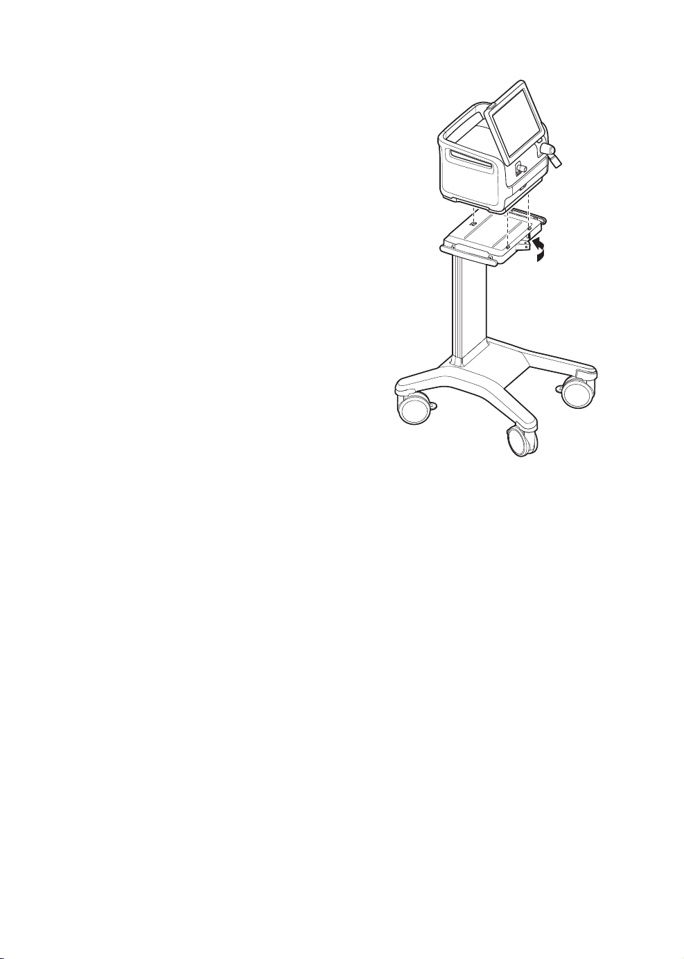
2.1 Ventilator
The ventilator consists of a user interface and
a patient unit.
Air is supplied from ambient air by an internal
turbine and O2 may be supplied by a medical
pipeline system or by gas cylinder.
2.1.1 Mounting on mobile cart
• Lock the wheels.
• Release the locking clamp on the mobile
cart.
• Stand directly in front of the mobile cart
when mounting the ventilator system.
• Tilt the ventilator system to fit the two front
clamps in position on the mobile cart.
• Press down the rear end of the ventilator to
fit the rear clamp in position.
• Lock the ventilator system to the mobile
cart with the locking clamp.
• Ensure that the patient unit is firmly fixed
to the mobile cart via the clamps and
locking clamp.
16
SERVO-airVentilator System v2.1, User's Manual
Page 17
| System Overview |
2 |
2
3
1
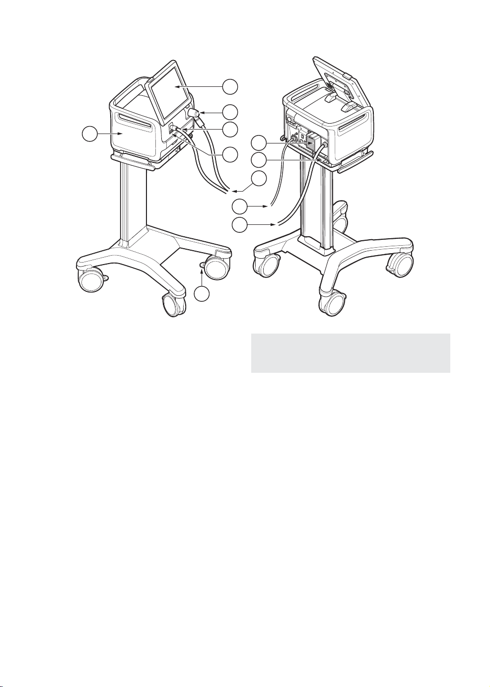
1. Patient unit
2. User interface
3. Expiratory inlet
4. Inspiratory outlet
5. Emergency air intake
6. Air inlet
7. Battery compartment
8. Patient circuit
9. AC mains power
10. O2 supply
11. Wheel lock
11
4
6
5
7
8
9
10
Note: Lock the wheels whenever the
ventilator system is standing still.
SERVO-airVentilator System v2.1, User's Manual
17
Page 18
| System Overview |
| 2
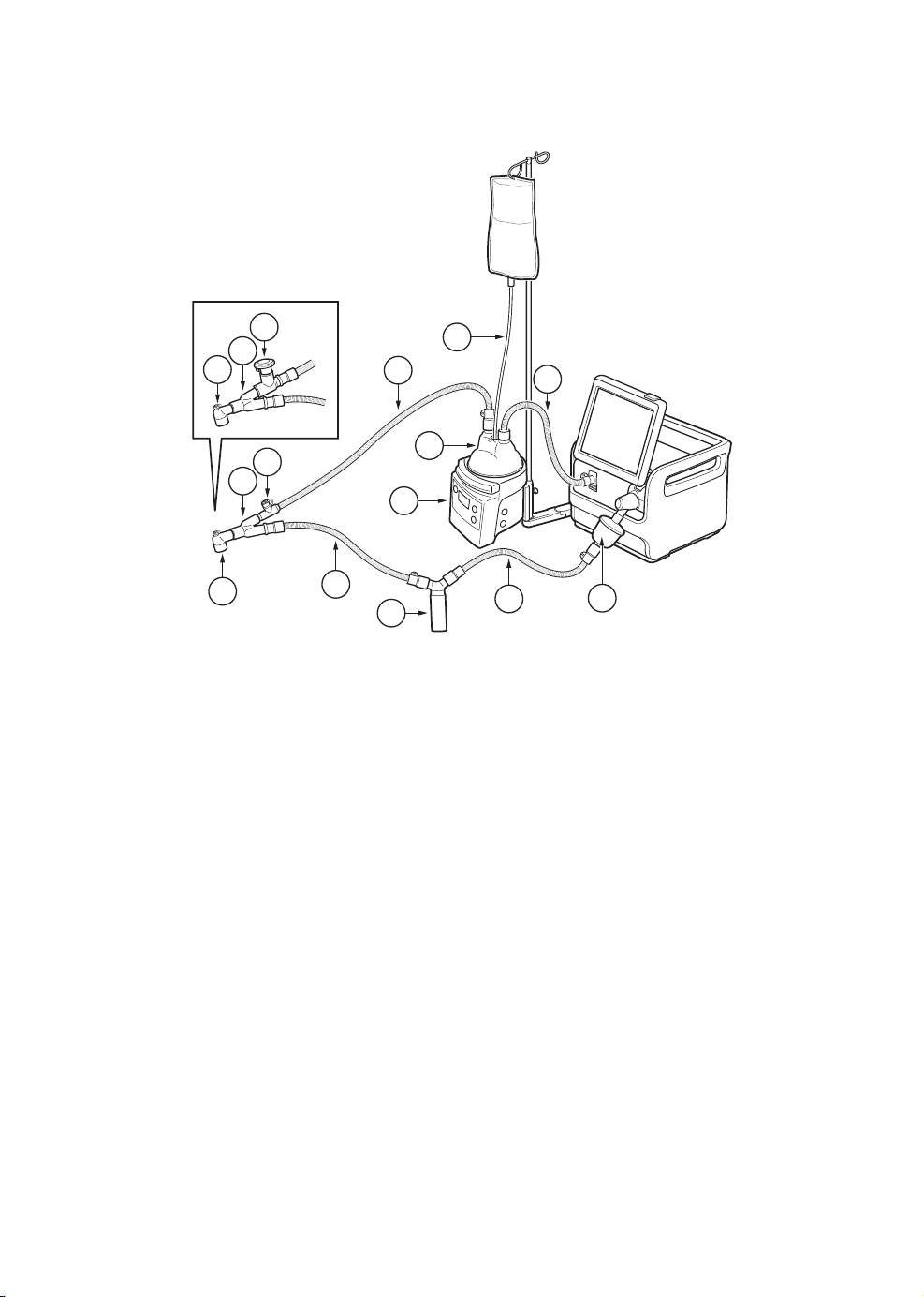
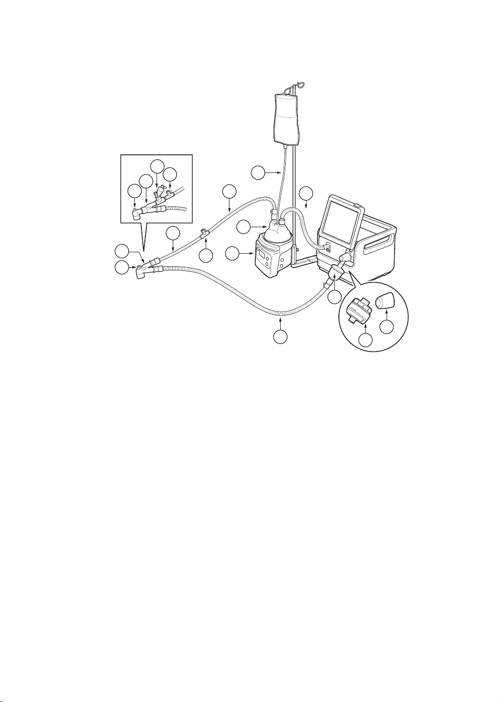
2.2 Patient unit
1
2
3
4
5
6 8 9 10
7
14
13
12
11
15
16
18
17
20
21
19
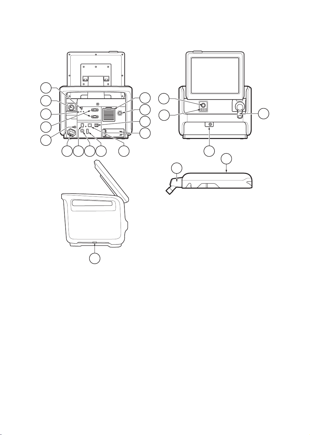
1. On/Off switch
The switch must be pulled downwards
before it can be switched.
2. Expiratory outlet
3. Power indicators
4. RS-232 connectors
5. Equipotentiality terminal.
6. AC mains power source connector with
fuse
7. Alarm output connection
8. External +12V DC inlet
9. Fuse for external DC power
10. Ethernet connection
18
11. Battery compartments
12. USB ports
13. Gas inlet for O
14. Gas inlet for air including air inlet filter
15. Inspiratory outlet
16. Emergency air intake
17. Nebulizer connector
18. Expiratory inlet
19. Cooling fan with filter (on both sides)
20. Expiratory cassette
21. Expiratory inlet with moisture trap
2
SERVO-airVentilator System v2.1, User's Manual
Page 19
| System Overview |
2 |
Important: No other external devices than
a USB memory stick may be connected to
the USB ports. Only one memory stick can
be used at the same time.
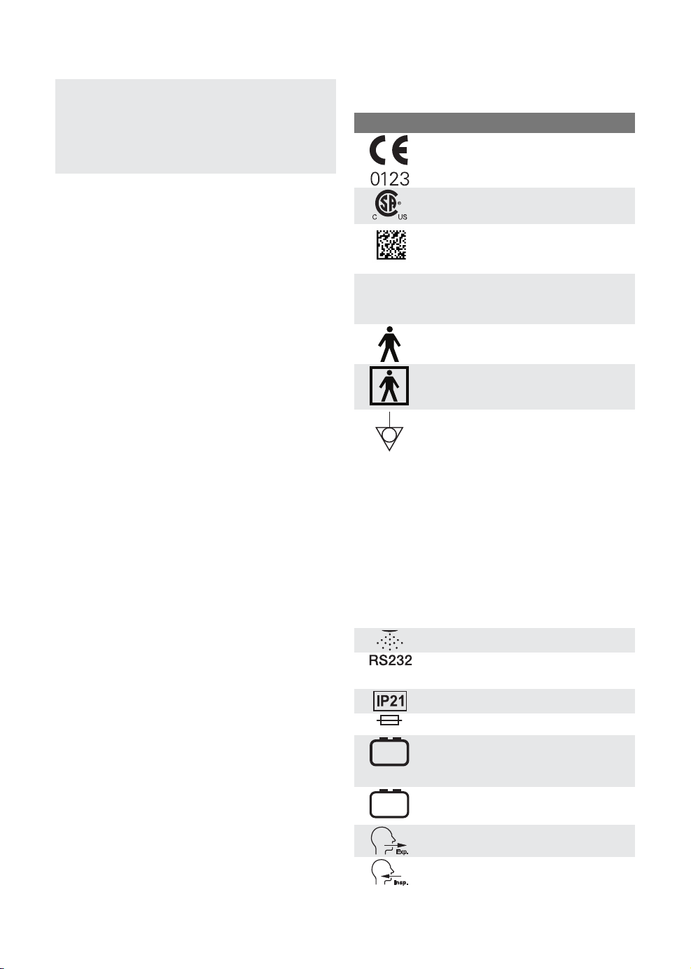
2.2.1 Symbols on patient unit
DescriptionSymbol
CE label—indicates compliance with
the requirements of the Medical
Device Directive 93/42/EEC
CSA label—Indicates compliance
with Canadian and US standards
UDI Label - Unique Device
Identification. Refer to section UDI
label on page 156.
Rx
ONLY
In USA, Federal law restricts this
device to sale by or on the order of
a physician.
Type B—indicates classification
according to IEC 60601-1
Type BF applied part — indicates
classification according to IEC
60601-1
Potential equalization terminal
Note: The potential equalization
terminal is designed for the
connection of a potential equalization
conductor according to DIN 42 801
and IEC 60601-1. The function of the
potential equalization terminal is to
equalize potentials between the
ventilator system and other medical
devices that can be touched
simultaneously. The potential
equalization terminal must not be
used for a protective earth
connection.
SERVO-airVentilator System v2.1, User's Manual
-
+
12V
-
+
Nebulizer connector
RS-232/Serial port - connector for
data communication
Ingress protection, IP21
Fuse (specification)
External 12V DC input
Battery
Expiratory gas flow from the patient
Inpiratory gas flow to patient
19
Page 20
| System Overview |
| 2
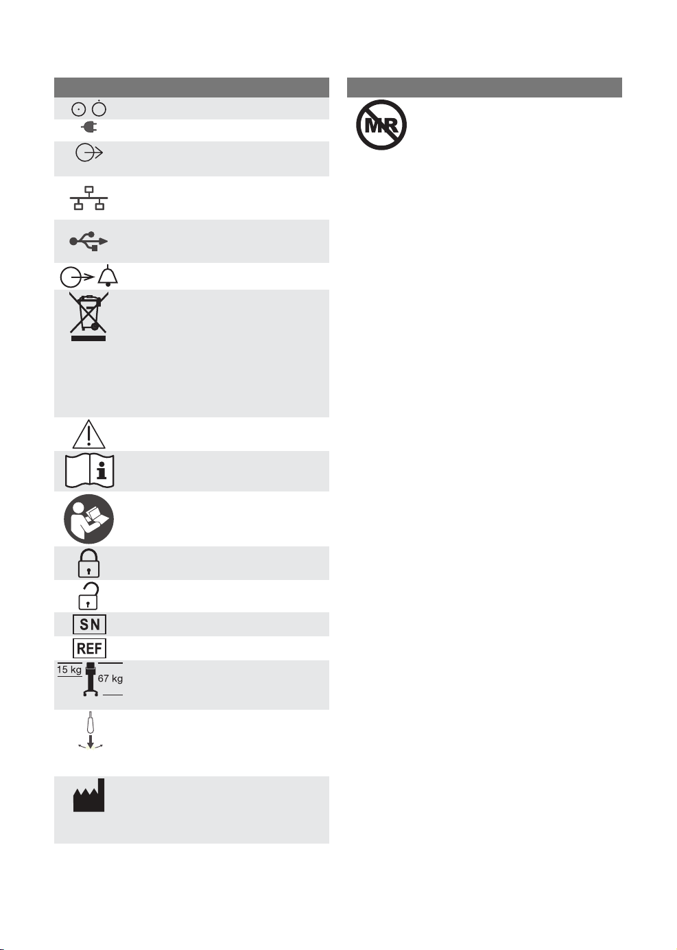
DescriptionSymbol
Mains power On/Off
Mains connected, batteries charging
Gas exhaust port—exhaust gas flow
from ventilator system
Network connection
USB connection
Alarm output connection
Special waste
Note: This product contains
electronic and electrical components.
Discard disposable, replaced and
left-over parts in accordance with
appropriate industrial and
environmental standards.
Caution
Consult instructions for use
DescriptionSymbol
MR Unsafe - keep away from
magnetic resonance imaging (MRI)
equipment.
20
Consult accompanying
documentation
Locked
Unlocked
Serial number
Order number
Weight of patient unit with user
interface and ventilator including its
safe working load.
Use of ON/OFF switch
The switch must be pulled
downwards before it can be
switched.
Manufacturer
The symbol is accompanied by
manufacturer address and
manufacturing date.
SERVO-airVentilator System v2.1, User's Manual
Page 21
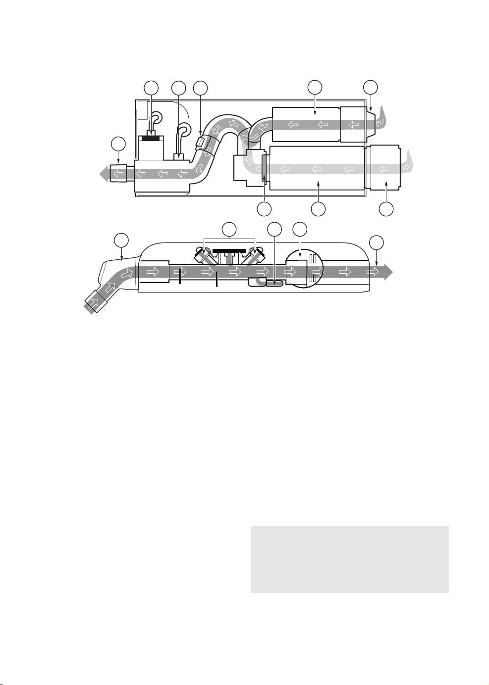
2.2.2 Gas flow through the patient unit
| System Overview |
2 |
8
6
7
9
11
10
1. Air inlet with air inlet filter.
2. Turbine module for ambient air.
3. The check valve prevents the gas to flow
backwards.
4. Gas inlet for O2.
5. The gas module for O2 regulates the O
gas flow.
6. The flow meter measures the gas flow.
7. The pressure of the gas delivered to the
patient is measured by the inspiratory
pressure transducer. The transducer is
protected by a bacterial filter.
2
5
3 1
2
4
12 13
14
10. The expiratory inlet in the expiratory
cassette contains a moisture trap.
11. The ultrasonic transducers in the
expiratory cassette measure the outgoing
gas flow.
12. The expiratory pressure transducer in the
expiratory cassette measures the pressure
in the patient circuit. The transducer is
protected by a bacterial filter.
13. The expiratory valve in the expiratory
cassette regulates the pressure in the
patient circuit.
14. Exhaust port.
8. The O2 cell measures the oxygen
concentration. The O2 cell is protected by
a bacterial/viral filter.
9. The inspiratory channel delivers gas to the
patient circuit inspiratory tubing and
contains a safety valve.
SERVO-airVentilator System v2.1, User's Manual
Note: The expiratory cassette can be
exchanged between different ventilator
systems. Always perform a pre-use check
after exchanging an expiratory cassette.
21
Page 22
| System Overview |
| 2
2.3 Batteries
2.3.1 Charging battery modules
Important: The battery modules are
delivered in shipping-mode and must be
charged before use.
To charge the battery modules, insert the
battery modules in the ventilator system. The
ventilator must be connected to mains. The
battery modules are charged automatically.
The batteries can also be charged with the
External battery charger, SERVO-air.
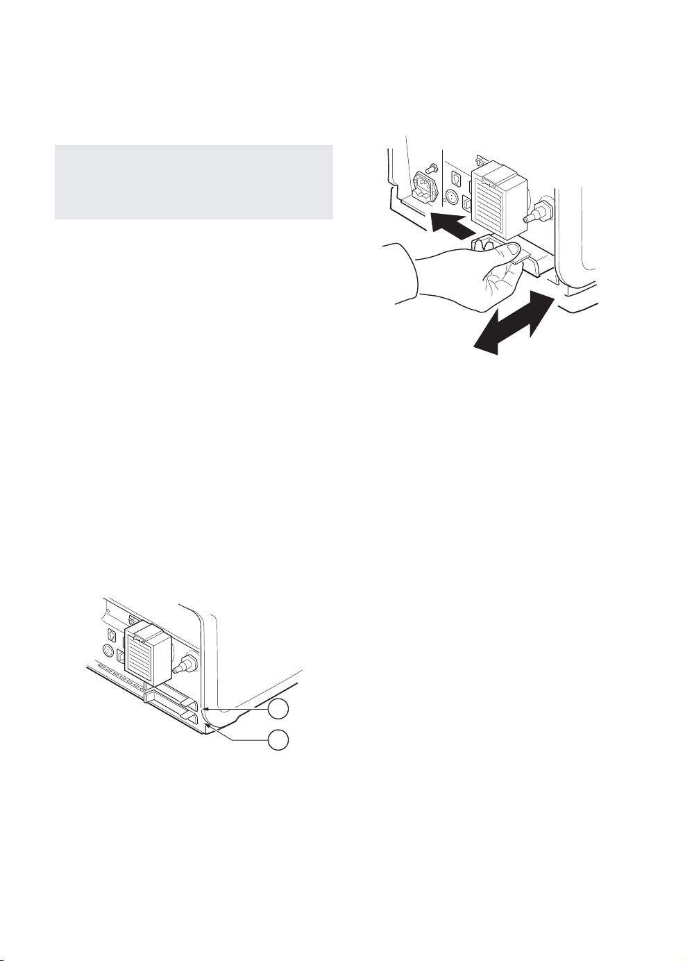
2.3.2 Handling battery modules
The battery compartment is divided into two
slots, 1 and 2.
The ventilator system uses the battery in slot
1 first. Make sure that the battery in slot 2 is
in place as a backup at all times during
ventilation.
Refer to section Battery on page 12.
• Remove the battery from the ventilator
system.
To insert a battery module:
• Hold onto the battery strap when inserting
a battery in the ventilator system.
When inserting a battery module in slot 1,
check that the battery strap for the battery
in slot 2 is not folded into the battery
compartment.
• Ensure that the battery is fully inserted so
that the release button returns to a
completely closed position.
1
2
1
2
The battery module in slot 1 may be
exchanged during ventilation.
To remove a battery module:
• Press the release button to the left and pull
the battery strap.
22
SERVO-airVentilator System v2.1, User's Manual
Page 23

| System Overview |
2 |
2.3.3 Battery status
Important:
• If Replace battery is displayed, the
battery is unreliable, regardless of the
operating time displayed under Batteries.
In this situation, replace the battery even
when the STATUS window indicates that
significant operating time remains.
• At least one battery module must always
be installed.
Detailed information about batteries is
accessed via SYSTEM STATUS/Batteries.
There is also an indication in the status bar
showing the power supply currently being
used by the ventilator system.
If the ventilator system is running on battery
power, the active battery in the battery symbol
turns yellow and the mains power symbol
disappears. The estimated remaining battery
time in minutes is always displayed, regardless
of the power supply in use.
The following information is displayed under
Batteries in SYSTEM STATUS for each
connected battery module:
• BATTERY CAPACITY – usable backup time
in minutes
An estimated backup time is shown in
Standby. This estimate may differ from the
actual usable backup time during running.
Usable backup time depends on set mode
and selected ventilation settings.
Note: The presented usable backup time
is the sum of the estimated operation
time displayed for each battery module
minus 20 minutes.
• Slot number
• Serial number
• Remaining operation time in minutes for
each battery
• Notification – may be displayed close to the
remaining operation time in minutes.
• Remaining battery life
The battery symbol also functions as a
shortcut to the window otherwise accessed
via SYSTEM STATUS/Batteries.
SERVO-airVentilator System v2.1, User's Manual
23
Page 24

| System Overview |
| 2
2.4 Patient circuit
Notes:
• Turn off the active humidifier during
nebulization.
• Expiratory filter connection is mandatory
during nebulization.
• A water trap is recommended if a single
heated patient circuit is used.
• Thermoshell, expiratory cassette must
be used when using heated expiratory
tubing or Expiratory heater Servo Duo
Guard.
• To ensure that the inspiratory gas
temperature is below 43°C the patient
circuit inspiratory tube must be at least
1.2 m to let the gas cool down.
Refer to System Flow Chart, SERVO-air for
information regarding patient circuit
configurations to be used with the ventilator
system.
24
SERVO-airVentilator System v2.1, User's Manual
Page 25
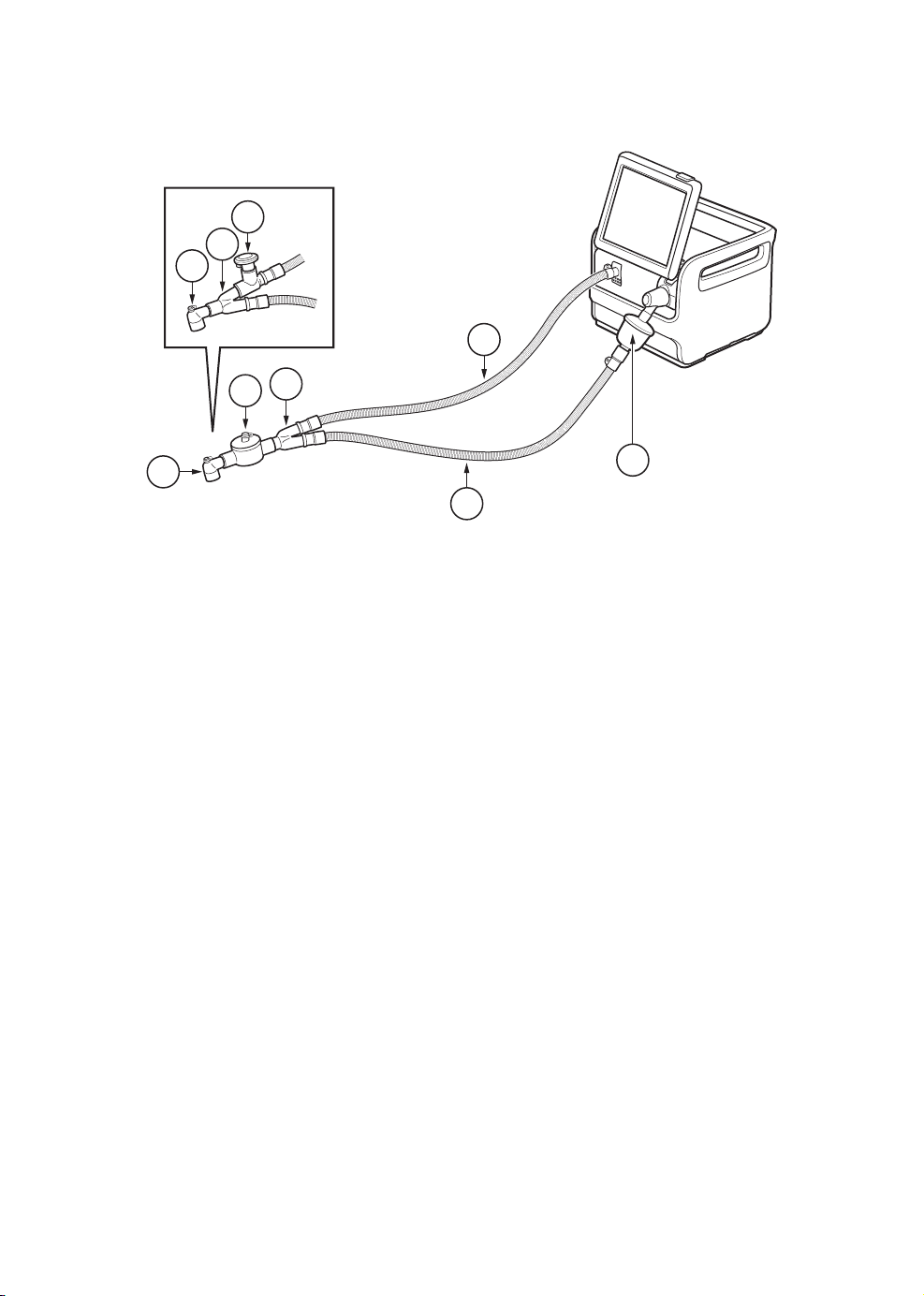
15 - 22 mm Ø patient circuit, reusable
5
2
4
2
3
| System Overview |
2 |
1
4
1. Inspiratory patient tube
2. Y piece
3. Heat and moisture exchanger (HME)
4. Angled adapter for endotracheal tube
7
6
5. Aerogen Pro
6. Expiratory patient tube
7. Expiratory filter
SERVO-airVentilator System v2.1, User's Manual
25
Page 26
| System Overview |
| 2
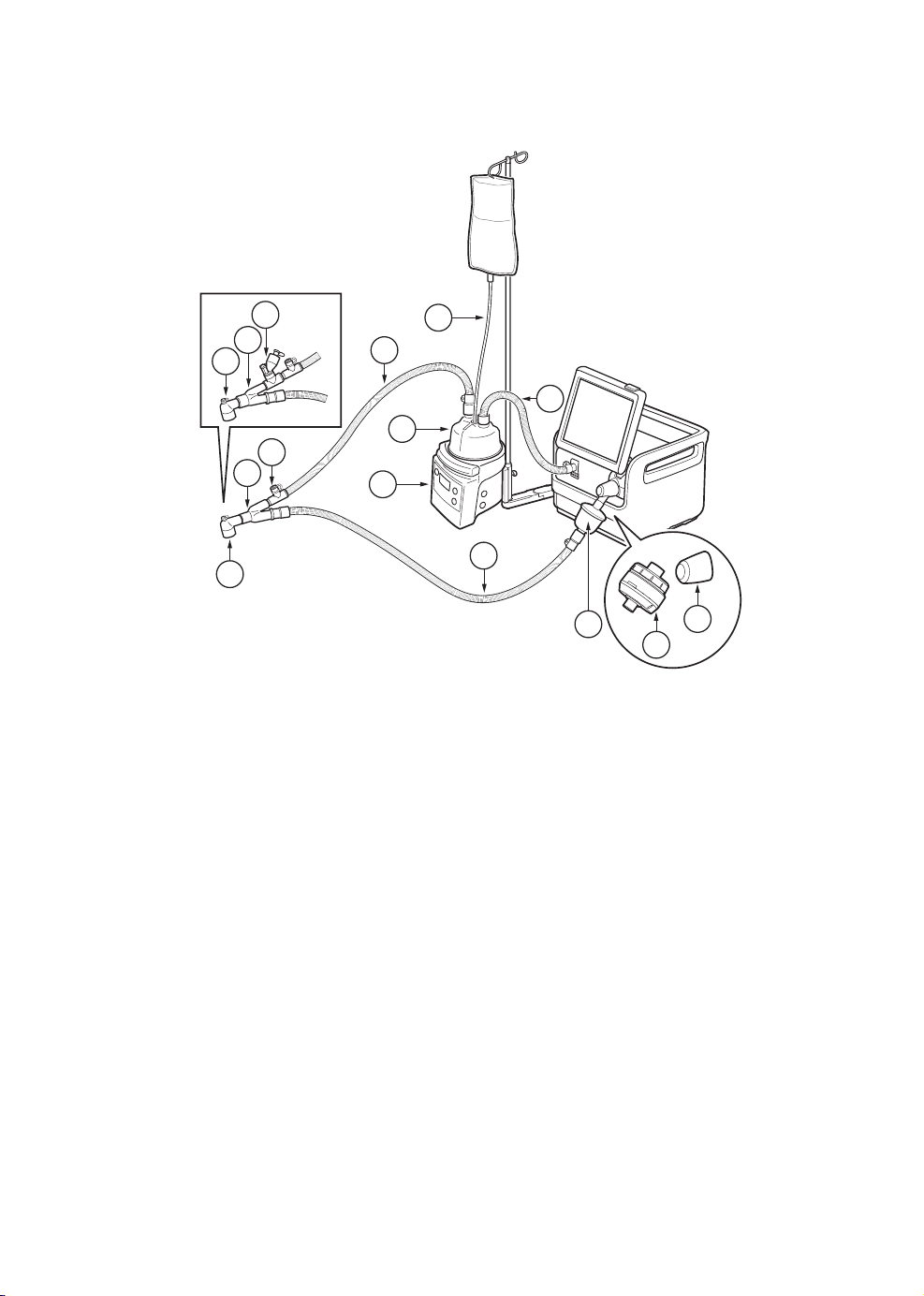
22 mm Ø patient circuit, dual heat disposable
8
6
7
5
6
7
1. Inspiratory patient tube
2. Water autofill
3. Humidification chamber
4. Active humidifier
5. Cuff with temperature port
6. Y piece
2
1
1
3
4
9
10
12
11
7. Angled adapter for endotracheal tube
8. Aerogen Solo
9. Expiratory patient tube
10. Expiratory filter
11. Expiratory heater Servo Duo Guard
12. Thermoshell, expiratory cassette
26
SERVO-airVentilator System v2.1, User's Manual
Page 27
10 mm Ø patient circuit, single heat reusable
| System Overview |
2 |
9
6
8
5
6
7
1. Inspiratory patient tube
2. Water autofill
3. Humidification chamber
4. Active humidifier
5. Cuff with temperature port
6. Y piece
10
11
2
1
1
3
4
10
7. Angled adapter for endotracheal tube
8. Pressure line connection port
9. Aerogen Pro
10. Expiratory patient tube
11. Water trap
12. Expiratory filter
12
SERVO-airVentilator System v2.1, User's Manual
27
Page 28
| System Overview |
| 2
10 mm Ø patient circuit, dual heat disposable
11
5
10
9
6
7
8
1. Inspiratory patient tube
2. Water autofill
3. Humidification chamber
4. Active humidifier
5. Cuff with temperature port
6. Extension tube for incubator use
7. Angled Y piece
8. Pressure line connection port
2
1
1
3
4
5
13
15
12
9. Angled adapter for endotracheal tube
10. Y piece
11. Aerogen Solo
12. Expiratory patient tube
13. Expiratory filter
14. Expiratory heater Servo Duo Guard
15. Thermoshell, expiratory cassette
14
28
SERVO-airVentilator System v2.1, User's Manual
Page 29
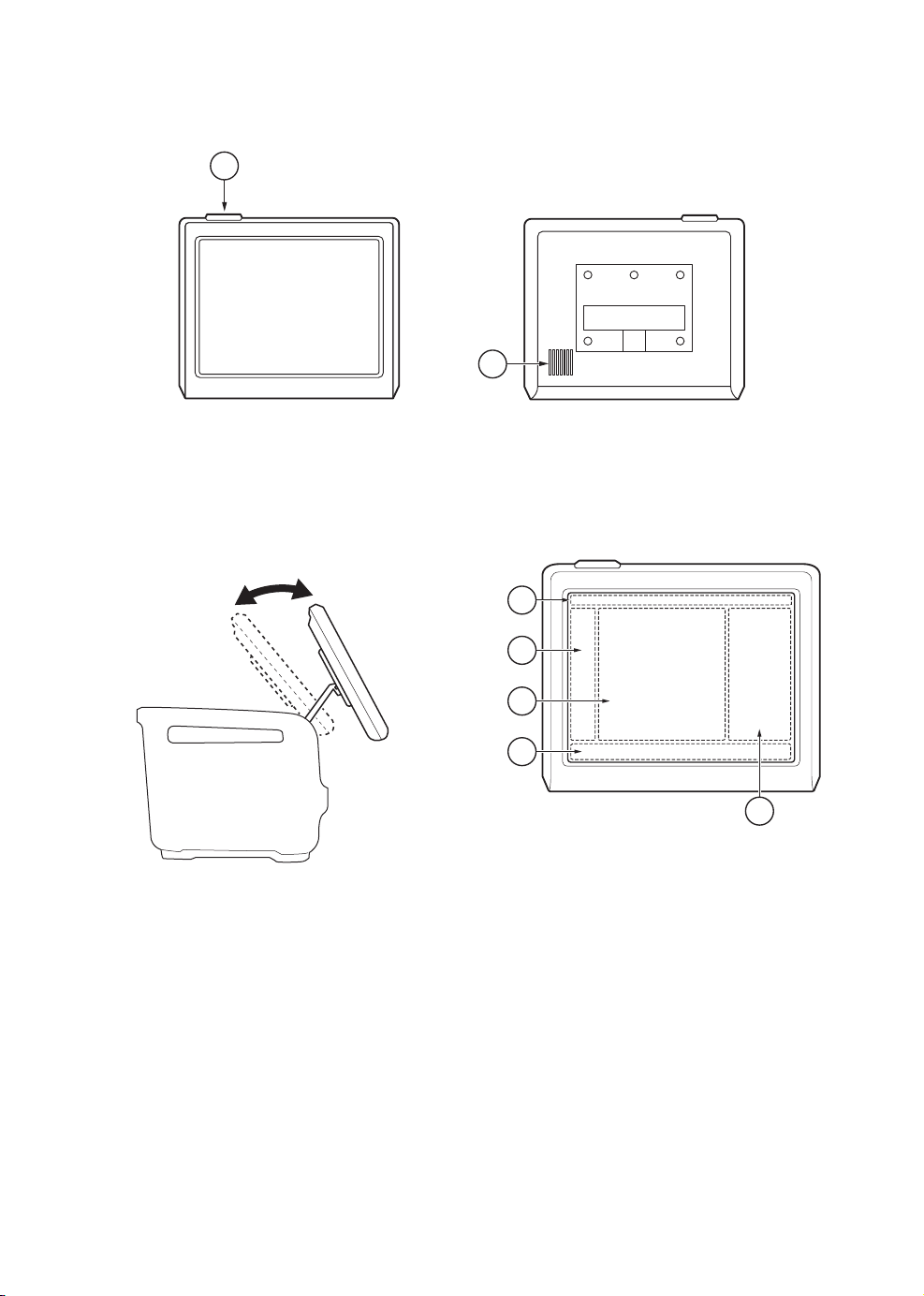
2.5 User interface
1
2.5.1 User interface adjustment
2
2. Loudspeaker1. Alarm indicator
2.5.2 Interactive areas
| System Overview |
2 |
The user interface can be adjusted into
different positions.
1
2
3
4
5
The user interface is completely touch based
and is divided into the following areas:
1. Status bar
2. Quick menu/extended menu
3. Display area
4. Direct access bar/media bar
5. Numerical values
SERVO-airVentilator System v2.1, User's Manual
29
Page 30
| System Overview |
| 2
Important:
• Do not use sharp tools on the screen.
• Fluid on the screen can disturb touch
functionality.
2.5.3 Navigating
To navigate the user interface, adjust settings
and get support:
• Tap (the touchpad changes color when the
navigating is registered).
• Tap and hold
• Scroll vertically or horizontally
• Drag and drop
2.5.4 User support
The user is supported by the following:
• Alarm management
• Safety scales
• Dynamic images
• Information texts
• Pre-use check instructions
• Shortcuts
• Prompts
Note:
The following colors are used for settings:
• Red — not recommended
• Yellow — use with caution
• Green — normal
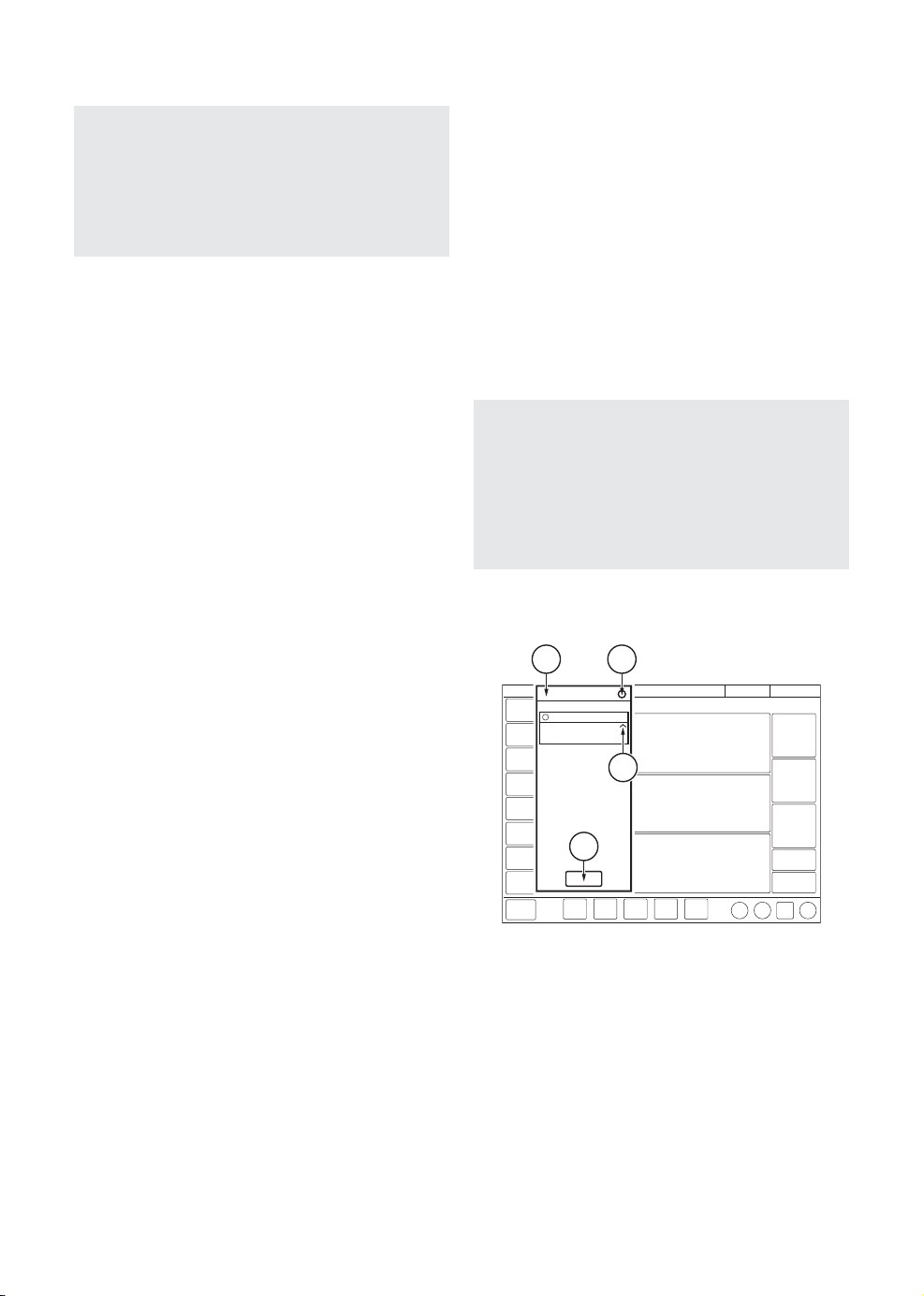
Alarm management
1
2
30
3
4
1. Alarm list
2. Number of active alarms
3. Alarm management checklist
4. Alarm history
Refer to chapter Alarm handling on page 109.
SERVO-airVentilator System v2.1, User's Manual
Page 31

| System Overview |
2 |
Safety scales
5
35
1 3
1. Slide bar
2. Increase/decrease setting
3. Full settings range
4. Accept
5. Cancel
Refer to section Safety scales on page 41.
Dynamic images
2
4
Information texts
1
2
1. Information text is available.
2. Indication that more information is
available by scrolling vertically in the
middle of the information window.
Shortcuts
Some frequently used functions can be
accessed via a shortcut. There are shortcuts
to the following windows:
• Alarm limits
• Patient data
• Battery status
• Leakage compensation deactivation
• Circuit compensation deactivation
• Nebulization
The dynamic image illustrates the effects of
the changes made to selected ventilation
settings.
SERVO-airVentilator System v2.1, User's Manual
Refer to section Symbols on user interface on
page 32.
31
Page 32

| System Overview |
| 2
Prompts
Prompts indicate that input is required.
2.5.5 Symbols on user interface
DescriptionSymbol
Extended menu show/extended
menu hide
Start ventilation
Stop ventilation/Standby
Do not push the user interface as the
ventilator system may tip over.
Alarm limits/Alarm limits shortcut
Audio pause
Audio paused
Audio off
Audio pause - all alarms, active and
inactive are pre-silenced.
Alarm on
32
Alarm off
Check alarms
Alarm sound level
Alarm history
Message
Number of messages
Adult/patient data shortcut
Pediatric/patient data shortcut
AC mains power
Missing battery
Unknown battery (not a Maquet
battery)
SERVO-airVentilator System v2.1, User's Manual
Page 33

| System Overview |
2 |
DescriptionSymbol
Charging battery
1
2
Total battery capacity, active battery
xx min
and battery status shortcut
External 12V DC power
DescriptionSymbol
Screen layout
Disconnect
Service & Settings
Biomed
Backup on
Backup off
Circuit compensation on
Circuit compensation off/Circuit
Service
Remote services
Exit
compensation deactivation shortcut
Invasive ventilation adult
Nebulization period/Nebulization
shortcut
Continuous nebulization/Nebulization
Invasive ventilation pediatric
Non invasive ventilation adult
100
O2 BOOST
shortcut
O2 boost locked to 100 %
Pneumatic trigger, pressure/flow
Non invasive ventilation pediatric
Organize
Two overlay loops
Reference loop
Panel locked
Panel unlocked
Loop grid on
Progress
Loop grid off
Full settings range
Compensation
Normal settings range
Configuration
Maneuvers
Recorder
Recording waveforms 30 seconds
Media
Modes
Patient data
System status
Trends & logs
Views
SERVO-airVentilator System v2.1, User's Manual
Recording waveforms in progress
Camera for taking screenshots
Value not within range
Uncertain value
Test failed (red)
Test not performed (yellow)
33
Page 34

| System Overview |
| 2
DescriptionSymbol
Test passed (green)
Accept
Decrease
Increase
Information text
Cancel (red)
Close (green)
Switch between main/backup modes
Additional values & settings
hide/Additional values & settings
show
Additional information hide/Additional
information show
2.5.6 Symbols on accessories and
packaging
DescriptionSymbol
CE label—indicates compliance with
the requirements of the Medical
Device Directive 93/42/EEC
Order number
Number to identify the production
batch
QTY
Quantity
Outer diameter in mm
Inner diameter in mm
Indicates the inner diameter of the
endotracheal tube
Circumference/lengthFr/cm
Use by date
Do not re-use. Single use only.
Rx
ONLY
Do not use if packaging is damaged
Consult accompanying
documentation
Keep away from sunlight
Manufacturer
The symbol is accompanied by
manufacturer address and
manufacturing date.
Manufacturing date
In USA, Federal law restricts this
device to sale by or on the order of
a physician.
Recyclable material. Recycling must
be performed in accordance with
appropriate industrial and
environmental standards.
34
SERVO-airVentilator System v2.1, User's Manual
Page 35

| System Overview |
2 |
DescriptionSymbol
Special waste to be disposed of in
accordance with appropriate
DescriptionSymbol
The support arm must be folded
during transport.
industrial and environmental
standards
Pb
Gas cylinder
Locked
Defibrillation proof Type CF applied
part - indicates classification
according to IEC 60601-1
Type BF applied part — indicates
classification according to IEC
60601-1
Type B—indicates classification
according to IEC 60601-1
Humidity limitation
+55oC
Temperature limitation
o
-10
C
Fragile — handle with care
Unlocked
Consult instructions for use
Keep away from water
This way up — indicates correct
upright position of the transport
package
Atmospheric pressure limitation
Do not expose to heat or fire.
Do not expose to mechanical force.
Do not dismantle, open or shred.
SERVO-airVentilator System v2.1, User's Manual
35
Page 36

| System Overview |
| 2
2.6 Transport
2.6.1 Before intrahospital transport
Before transporting the ventilator system with
or without a patient connected, follow facility
guidelines and:
• Be sure that the patient unit is securely
attached and locked.
• Be sure that all accessories such as battery
modules, gas cylinder, and humidifier are
securely attached and locked.
• Be sure that the gas cylinders are
connected and have sufficient gas.
• Be sure that the straps are firmly wrapped
across the center of the gas cylinders so
that the cylinders do not move during
transport.
• Be sure that the battery in slot 2 is fully
charged.
• Inspect the resuscitator.
• Inspect the mobile cart for damage.
• Be sure that the support arm is folded
before transport.
2.6.2 During intrahospital transport
While transporting the ventilator system with
or without a patient connected, follow facility
guidelines and:
• Use the handles on the patient unit.
• Transport the bed and the ventilator system
slowly, and watch the patient connection
carefully to see that no pulling or other
movement occurs.
• If triggering problems occur during
intrahospital transport because of extreme
vibrations, Pressure Control mode is
recommended or to set the trigger so that
it is less sensitive.
• Be careful not to tip the mobile cart when
crossing an obstacle like a threshold.
• On arrival, connect the ventilator system to
mains power and lock the brakes.
CAUTION: Do not load the ventilator
equipment asymmetrically on the ventilator
system to avoid instability.
36
SERVO-airVentilator System v2.1, User's Manual
Page 37

3 Operation overview Table of contents
| Operation overview |
38|Workflow summary3.1
38|Pre-use check3.2
39|Patient circuit test3.3
40|Select patient category3.4
40|Select ventilation type3.5
41|Set ventilation mode3.6
42|Set alarm limits3.7
43|Enter patient data3.8
44|Start ventilation3.9
44|Stop ventilation3.10
3 |
SERVO-airVentilator System v2.1, User's Manual
37
Page 38

| Operation overview |
| 3
3.1 Workflow summary
• Turn on the ventilator system, prepare the
patient circuit to be used and perform a
pre-use check.
• Select patient category.
• Select invasive or non invasive ventilation.
• Set the ventilation mode.
• Check, and if necessary, adjust the alarm
limits.
• Enter data for the new patient, including
height, weight, and gender (optional).
• Start ventilation and connect the ventilator
system to the patient.
• Adjust alarm limits if necessary.
Stop ventilation when desired.
3.2 Pre-use check
The pre-use check contains a number of tests
that the ventilator system automatically
performs.
Refer to section Pre-use check tests on
page 140.
Each test starts automatically when the
previous test is completed.
To ensure correct system functionality, optimal
performance and patient safety, a pre-use
check must be performed.
WARNINGS!
• Always perform a pre-use check before
connecting the ventilator system to a
patient.
• Do not connect the ventilator system to
a patient while a malfunction persists.
38
Important:
• When the pre-use check is completed,
all sources of alarm signals and alarm
conditions have been verified and the
alarm system operates correctly.
• The volume of the patient circuit used
during pre-use check should be the same
as during ventilation.
If the patient circuit is changed after the
pre-use check is completed, perform a
new pre-use check or a patient circuit
test.
SERVO-airVentilator System v2.1, User's Manual
Page 39

| Operation overview |
3 |
3.2.1 Start pre-use check
• Connect the ventilator system to a mains
power outlet.
• Connect the ventilator system to O2 gas
supply.
• Turn the ventilator system on.
Refer to section Patient unit on page 18.
• Ta p PRE-USE CHECK in STANDBY.
• Tap Ye s in the PRE-USE CHECK window
to start, and follow on-screen instructions.
3.2.2 Complete pre-use check
A symbol and a color marking appear on
screen for each pre-use check test, as
appropriate: Passed, Failed and Not
performed.
• Tap OK to confirm or tap Redo test to
restart a pre-use check test.
The ventilator system returns to STANDBY
when the pre-use check is completed.
3.3 Patient circuit test
In Standby, the patient circuit test may be
performed separately from the pre-use check.
CAUTION: The patient circuit test must be
performed with a complete patient circuit,
including all accessories (e.g. active
humidifier filled with water, filter and
nebulizer), that is to be used with the
patient.
The patient circuit test measures resistance
and compliance in the patient circuit. If the
patient circuit is changed and no new patient
circuit test is performed, the ventilator will
compensate incorrectly based on the
measurements of the previous patient circuit.
If the correct circuit is not tested, the following
risks may arise:
• In volume-based modes, the volume
delivered to the patient will be incorrect.
• In pressure-based modes, the volume
measured will be incorrect.
Notes:
• The status of the two latest pre-use
checks and patient circuit tests is
displayed under SYSTEM
STATUS/General.
• The status of the latest pre-use check
and patient circuit test is also displayed
in STANDBY.
SERVO-airVentilator System v2.1, User's Manual
Tap PATIENT CIRCUIT TEST and follow
on-screen instructions.
The result from the patient circuit test is
displayed in PATIENT CIRCUIT TEST in
STANDBY. Detailed result are displayed in the
SYSTEM STATUS/General window.
Important: The patient circuit test does not
replace the pre-use check.
39
Page 40

| Operation overview |
| 3
3.4 Select patient category
• Tap patient category in STANDBY. All
available patient categories appear.
• Select the appropriate patient category.
The patient data shortcut in the status bar
changes accordingly.
Important: Always check the alarm
settings after changing the patient category.
Notes:
• Changing the patient category affects
the following settings:
- default values for alarm limits
- allowed ranges for alarm limits
- default values for ventilatory settings
- allowed ranges for ventilatory settings
- pressure and flow regulation
- scaling
3.4.1 Change patient category
To change the patient category during
ventilation:
• Tap the patient data shortcut in the status
bar or tap PATIENT DATA in the quick
menu.
• Select the appropriate patient category.
• Follow on-screen instructions.
3.5 Select ventilation type
• Select invasive or non invasive ventilation
in STANDBY.
Note: The default values may have been
changed by a previous user.
• The default values may have been
changed by a previous user.
40
SERVO-airVentilator System v2.1, User's Manual
Page 41

| Operation overview |
3 |
3.6 Set ventilation mode
• Tap MODES in STANDBY to open the
MODES window.
• Select mode.
Note: Tap and hold the tile to access
more information about the selected
mode.
• When a ventilation mode has been selected,
all parameters can be set in the mode
settings window.
• Tap a parameter to adjust its value.
• Tap Accept to confirm, or Cancel to cancel
the settings.
3.6.1 Settings
Important: If one or several settings in the
mode settings window are highlighted in
yellow, this indicates that it/they should be
considered for adjustment, as the values
entered there may have been carried over
from the previous mode.
3.6.2 Safety scales
5
35
1 3
1. Slide the bar to the right or left to increase
or decrease the settings. The bar displays
the safety scale, that is the range that is
safe to use for most patients.
2. Tap to incrementally increase or decrease
the setting. Tap and hold to rapidly
increase or decrease the setting.
3. Tap on full settings range to extend the
safety scale setting range.
4. Confirm the setting by tapping Accept.
5. Exit settings without changing by tapping
cancel.
2
4
Refer to section Ventilatory settings on
page 142.
SERVO-airVentilator System v2.1, User's Manual
41
Page 42

| Operation overview |
| 3
3.7 Set alarm limits
• Tap ALARM LIMITS in the quick menu.
• The limits are set in the alarm limit bars in
the ALARM LIMITS window.
• Tap the upper or lower value in the selected
alarm limit bar.
• A scale appears, tap plus or minus or slide
the bar to set the value.
Confirm each setting by tapping Accept.
Tap Autoset all alarms, if desired, to get alarm
limit proposals for the following modes:
-VC
-PC
-PRVC
42
Important: Before accepting Autoset all
alarms values, make sure they are
appropriate for the patient. If not, enter
settings manually.
SERVO-airVentilator System v2.1, User's Manual
Page 43

| Operation overview |
3 |
To activate the new alarm limits tap Accept.
Note: Autoset all alarms is not available in
supported or NIV modes or in STANDBY
because the ventilator system requires
patient values in order to propose alarm
limits.
3.7.1 Set alarm sound level
The ambient sound needs to be taken into
consideration when setting the alarm sound
level.
• Tap ALARM LIMITS in the quick menu.
• Tap alarm sound level.
3.8 Enter patient data
• Tap the patient data shortcut in the status
bar or tap PATIENT DATA in the quick
menu.
• Tap in the selected input field to open a
keyboard or keypad.
• Tap Accept to confirm new data.
• Enter/edit the following data:
- Patient category
- Name
- Date of birth / ID
- Gender
- Height
- Weight
Note: If gender, height and weight have
been entered, predicted body weight will
be automatically displayed.
10
• Tap the sound level bar to set appropriate
alarm sound level.
• Tap Accept.
Refer to section Predicted body weight
(PBW) on page 91.
• Tap Done when entry is complete.
SERVO-airVentilator System v2.1, User's Manual
43
Page 44

| Operation overview |
| 3
3.9 Start ventilation
Tap START VENTILATION in STANDBY or
START in the quick menu to start ventilation.
WARNING! Ventilation must be started
manually when a patient is connected to
the ventilator system.
3.10 Stop ventilation
To disconnect and stop ventilation:
• Physically disconnect the patient from the
ventilator system.
• Tap STANDBY in the quick menu.
• Tap and hold STOP VENTILATION to stop
ventilation.
44
SERVO-airVentilator System v2.1, User's Manual
Page 45

4 Displaying and saving data Table of contents
| Displaying and saving data |
46|Views4.1
49|Displaying waveforms4.2
50|Displaying numerical values4.3
50|Trends and logs4.4
51|Saving and exporting data4.5
53|Ventilator configuration4.6
54|System status4.7
4 |
SERVO-airVentilator System v2.1, User's Manual
45
Page 46

| Displaying and saving data |
| 4
4.1 Views
The ventilator system offers different views to
suit different needs. They are accessed via the
quick menu during ventilation.
4.1.1 Basic view
Note: All non invasive ventilation modes
start in the BASIC view.
It is possible to adjust the layout by tapping
either SCREEN LAYOUT in the extended menu
or VIEWS/Screen layout in the quick menu.
This makes it possible to show or hide the
volume waveform.
Refer to section Adapting the waveform
display on page 49.
It is also possible to adjust the scaling, sweep
speed, appearance of the waveforms and user
interface brightness in the SCREEN LAYOUT
window.
The view consists of:
• two or three waveforms – pressure and flow
waveforms are always present, together
with the volume waveform, if desired
• a single column of numerical values
46
SERVO-airVentilator System v2.1, User's Manual
Page 47

| Displaying and saving data |
4 |
4.1.2 Advanced view
The view consists of:
• two to three waveforms – pressure and flow
waveforms are always present, together
with the volume waveform, if desired
• two columns of numerical values
Note: All invasive ventilation modes start in
the ADVANCED view.
It is possible to adjust the layout by tapping
either SCREEN LAYOUT in the extended menu
or VIEWS/Screen layout in the quick menu.
Refer to section Adapting the waveform
display on page 49.
4.1.3 Loops view
This view provides a graphical representation
of the relationship between pressure-flow,
pressure-volume and volume-flow.
The view consists of:
• up to three loops – pressure-flow,
pressure-volume and volume-flow
• two to three waveforms – pressure and flow
waveforms are always present, together
with the volume waveform, if desired
• two columns of numerical values
Note: The LOOPS view is not available in
non invasive modes.
SERVO-airVentilator System v2.1, User's Manual
It is possible to adjust the layout by tapping
either SCREEN LAYOUT in the extended menu
or VIEWS/Screen layout in the quick menu.
It is also possible to adjust the scaling, sweep
speed, appearance of the waveforms and user
interface brightness in the SCREEN LAYOUT
window.
Refer to section Adapting the waveform
display on page 49.
47
Page 48

| Displaying and saving data |
| 4
In addition, all loops can be shown or hidden.
The maximum number of loops displayed is
three, in which case no more than three
waveforms may be displayed. The loops may
also be displayed with or without a loop grid
by tapping Loop grid.
To store a reference loop or see two overlaid
loops simultaneously:
1. Tap the reference loop symbol. A
reference loop will then be displayed
together with a time stamp.
2. Tap the two overlay loops symbol to
display the two previous loops.
4.1.4 Family view
4.1.5 Distance view
The view is designed for optimal readability
from a distance. Information displayed
includes numerical values and waveforms.
There are six large tiles displaying:
• five enlarged numerical values
• the pressure and flow waveforms
The screen layout cannot be adjusted.
The view has a neutral background image and
may be used during family visits to hide the
standard user interface.
Displayed information is minimized to:
• one column of numerical values
• the direct access bar
• alarms and messages in the status bar
• a dynamic representation (moving bubbles)
showing that ventilation is in progress.
The screen layout cannot be adjusted.
Tap anywhere on the screen for rapid access
to the most recently used view.
48
SERVO-airVentilator System v2.1, User's Manual
Page 49

| Displaying and saving data |
4 |
4.2 Displaying waveforms
The ventilator system can display a minimum
of two waveforms and a maximum of three,
depending on the view selected.
Pressure and flow waveforms are always
mandatory except in the FAMILY view.
The waveforms displayed on the user interface
are:
• pressure – (yellow)
• flow – (green)
• volume – depending on view selected and
layout adjustments (blue)
4.2.1 Adapting the waveform display
It is possible to adapt the waveform display
via the scaling function.
• Tap and hold a displayed waveform.
• In the window that opens, adjust the scaling
function manually or use Auto to scale
automatically.
• To close the window, tap anywhere on the
screen other than the opened window.
Alternatively:
• Adjust the layout by tapping either SCREEN
LAYOUT in the extended menu
orVIEWS/Screen layout in the quick menu.
• Tap the tile shown in the figure directly to
the left of each waveform name.
It is also possible to show or hide
non-mandatory waveforms in the SCREEN
LAYOUT window.
The sweep speed can be adjusted by tapping
Sweep speed and selecting either of three
speeds.
In addition, there is a choice under
Appearance between filled and unfilled
waveforms.
SERVO-airVentilator System v2.1, User's Manual
49
Page 50

| Displaying and saving data |
| 4
4.3 Displaying numerical values
During ventilation, numerical values (measured
or calculated) are displayed on the right side
of the screen.
20
10
25
• Alarm limits (if applicable) are displayed in
small digits for each numerical value.
• Values that are off the scale are replaced
by three asterisks.
• Values that are uncertain are indicated by
a single asterisk.
Depending on the view, either one or two
columns of numerical values are displayed.
To access additional values, tap the arrow at
the right edge of the screen to display all
numerical values.
4.4 Trends and logs
4.4.1 Trends
Trend values are stored every 60 seconds and
retained for a maximum of 72 hours. Stored
events and system changes are also displayed
here.
To view trends:
• In the extended menu, tap TRENDS &
LOGS /TRENDS.
• To adjust the time resolution, tap the
number of hours displayed.
• The time valid for the cursor position is
displayed. If events have been stored, their
number is displayed in the circle shown in
the figure and an explanation appears to
the left of this circle.
• If a recording is saved at a time
corresponding to the cursor position, a
recorder is displayed. To view the recording,
tap this recorder.
50
• Tap Organize trends to place the trends in
the desired order by dragging and dropping
the different trended values presented.
Refer to section Trends on page 147.
SERVO-airVentilator System v2.1, User's Manual
Page 51

| Displaying and saving data |
4 |
4.4.2 Logs
To view the event log:
• In the extended menu, tap TRENDS &
LOGS /LOGS.
• Scroll among all the events listed.
• The LOGS window offers a search function.
Tap the text field to open the keyboard and
enter a search word. To display only log
items that contain the search word entered,
tap Filter. Tap again to deactivate the filter.
• Use the backspace arrow to delete the
search word.
Each event includes the event time and date.
The event log is cleared when a new patient
is admitted.
4.5 Saving and exporting data
Data can be saved in a number of ways:
• as screenshots
• as recordings
• as files for export including event log, trends
and both the above.
The screenshots and recordings are stored
under MEDIA.
Data can later be exported to a USB memory
stick.
4.5.1 Saving screenshots
To save a screenshot, tap the camera in the
status bar.
Refer to section Event log on page 148.
SERVO-airVentilator System v2.1, User's Manual
The screenshot will be stamped with the date
and time it was taken and saved under the
Saved screens tab in the MEDIA window.
There is space for 40 screenshots under this
tab. When the space is full, the next
screenshot taken will erase the oldest one.
51
Page 52

| Displaying and saving data |
| 4
4.5.2 Viewing saved screens
To view screenshots, tap MEDIA in Saved
screens. Choose the relevant screenshot
displayed at the bottom of the window. If there
are more than ten screens saved, scroll to the
right to find more.
4.5.3 Recording waveforms
To make a recording, tap the recorder (not
available in Standby) in the status bar.
A 30 second long recording will be made
starting 15 seconds before, and lasting until
15 seconds after the time the recording was
initiated. A blue progress bar will be displayed
under the recorder while the recording is being
made.
4.5.4 Viewing recordings
To view recordings, tap TRENDS &
LOGS/MEDIA /Recordings in the extended
menu. Choose the relevant recording
displayed at the bottom of the window. If more
than ten recordings have been saved, scroll
to the right to find more.
The cursor (pale green) is positioned on the
dotted line indicating the middle point of the
recording. It is activated by moving it or by
pressing the arrows to the right of the recorder
seen above the dotted line. The values at the
cursor position are displayed in digits to the
right of the waveform name in the recording
window.
When viewing a recording, it is also possible
to view the settings by tapping Settings at the
bottom left of the window. This will open a list
of the actual parameter settings in use at the
time the recording was initiated.
The recording will be stamped with the date
and time that it was initiated and will be saved
under the Recordings tab in the MEDIA
window. All settings applying at the time the
recording is initiated will also be saved.
There is space for 40 recordings under this
tab. When the space is full, the next recording
made will erase the oldest one.
52
SERVO-airVentilator System v2.1, User's Manual
Page 53

| Displaying and saving data |
4 |
4.5.5 Exporting and deleting data
To export or delete screenshots or recordings,
tap TRENDS & LOGS/MEDIA /Export & Delete
in the extended menu.
Alternatively, tap the Export & delete tab.
Both screenshots and recordings can be
selected for export or deletion.
The additional choice of exporting files that
include other material is also given at the
bottom right of this window. To use this
function, tap Export files.
4.6 Ventilator configuration
The ventilator system will always start up with
the stored configuration settings.
To view the stored configuration settings, tap
CONFIGURATION in the extended menu:
The following configurations can be viewed:
• Alarms
• General
• Units
• Startup configuration
The alarms configuration can be viewed for
each of the patient categories. The other
configurations do not vary with patient
category.
Note: No editing can be done under
CONFIGURATION.
Refer to chapter Service & Settings on
page 123.
The following data will be exported to a USB
memory stick:
• Event log
• Trends
• Saved screens & recordings
Important: Only one USB memory stick
may be connected to the USB ports at the
same time.
SERVO-airVentilator System v2.1, User's Manual
53
Page 54

| Displaying and saving data |
| 4
4.7 System status
To view the current status of the ventilator
system:
• Tap SYSTEM STATUS in the quick menu
in Standby.
• Tap SYSTEM STATUS in the extended
menu during ventilation.
The SYSTEM STATUS window that opens
contains:
1. Installed options
2. General
3. Batteries
4. Expiratory cassette
5. Pre-use check
6. O2 cell
7. Patient circuit
8. Turbine
54
SERVO-airVentilator System v2.1, User's Manual
Page 55

5 Ventilation modes Table of contents
| Ventilation modes |
56|Introduction5.1
57|Pressure Control (PC)5.2
59|Pressure Regulated Volume Control (PRVC)5.3
61|Volume Control (VC)5.4
63|Bi-Vent/APRV5.5
65|Pressure Support (PS)/CPAP5.6
68|Volume Support (VS)5.7
71|Automode5.8
74|SIMV5.9
78|Non Invasive Ventilation (NIV)5.10
80|NIV Pressure Control (NIV PC)5.11
81|NIV Pressure Support (NIV PS)5.12
5 |
SERVO-airVentilator System v2.1, User's Manual
55
Page 56

| Ventilation modes |
| 5
5.1 Introduction
5.1.1 Safety guidelines
Not all safety guidelines apply to all modes.
WARNINGS!
• Autotriggering should be avoided. Do not
set the trigger level too low.
• The following warning apply to non
invasive ventilation (NIV) modes only:
- Avoid high inspiratory pressure as it
may lead to gastric overdistension and
risk of aspiration. It may also cause
excessive leakage.
Be sure to set alarm limits as appropriate for
each mode, especially those for:
- expired minute volume
- apnea time
- airway pressure
Important:
• To protect the patient’s lungs from
excessive pressure it is important to set
the upper pressure limit to a suitable
value.
• It is important to avoid leakage so as to
ensure the proper functioning of modes
such as:
-PRVC
-VS
- Automode PRVC ⇄ VS
- SIMV (PRVC) + PS
• The circuit compensation function should
be used – it is important to make sure
that the compressible volume of the
patient circuit is not changed after the
pre-use check/patient circuit test has
been performed (e.g. filling an active
humidifier with water or connecting a
filter after the test has been performed).
56
Note:
The ventilator system is delivered preset
with the following configuration options:
• Ventilatory settings are based on either
minute volume or tidal volume.
• Ventilatory settings are based on either
I:E ratio or inspiration time.
SERVO-airVentilator System v2.1, User's Manual
Page 57

5.2 Pressure Control (PC)
| Ventilation modes |
5 |
Pressure Control (PC):
• delivers a constant pressure over a preset
inspiratory time and at a preset respiratory
rate
• delivers the inspiration with a decelerating
flow
• changes in lung or thorax resistance or
compliance will affect the volume delivered
1234
567
The following parameters are set:
1. Oxygen concentration (%)
2. PEEP (cmH2O)
3. Respiratory rate (b/min)
4. PC above PEEP (cmH2O)
The delivered volume is dependent on the
pressure above PEEP, lung compliance and
resistance in the patient circuit and airways.
This means that the tidal volume can vary.
The flow during inspiration is decelerating. The
patient can trigger extra breaths. As the
delivered tidal volume can vary, it is very
important to set alarm limits for the minute
volume to adequate levels.
PC ventilation is often preferred when there is
leakage in the patient circuit, e.g. due to an
uncuffed endotracheal tube, or in situations
where the maximum airway pressure must be
controlled.
If a patient tries to exhale during inspiration,
pressure increases. When it increases
3 cmH2O above the set inspiratory pressure
level, the active expiratory valve opens and
regulates the pressure down to the set
inspiratory pressure level. If the pressure
increases to the set upper pressure limit, e.g.
if the patient is coughing, the expiratory valve
opens and the ventilator system switches to
expiration.
5. I:E ratio or Inspiration time (s)
6. Inspiratory rise time (% or s)
7. Trigger
Refer to section Settings on page 41.
SERVO-airVentilator System v2.1, User's Manual
57
Page 58

| Ventilation modes |
| 5
5.2.1 Pressure Control in detail
The circles in the figure indicate patient triggering.
• PC ensures that the preset inspiratory
pressure level is constant throughout
inspiration. Breaths are delivered in
accordance with the preset respiratory rate,
inspiration time and inspiratory pressure
level, resulting in a decelerating flow.
• The preset pressure level is controlled by
the ventilator system. The resulting volume
depends on the set pressure level, the
inspiration time and the mechanical
properties of the patient's lungs during each
breath.
• Inspiration starts in accordance with the
preset respiratory rate or when the patient
triggers.
Expiration starts:
• After the termination of the preset
inspiration time.
• If the upper pressure limit is exceeded.
58
SERVO-airVentilator System v2.1, User's Manual
Page 59

5.3 Pressure Regulated Volume Control (PRVC)
| Ventilation modes |
5 |
Pressure Regulated Volume Control (PRVC):
• combines the advantages of Volume
Control and Pressure Control by delivering
a preset tidal volume with a decelerating
inspiratory flow at a preset respiratory rate
• maintains the lowest possible constant
pressure throughout inspiration
• the inspiratory pressure of a breath will
never exceed 5 cmH2O below the upper
pressure limit
The ventilator system can be configured so
that either tidal volume or minute volume is
set.
1234
567
The flow during inspiration is decelerating. The
patient can trigger extra breaths.
5 cmH2O
The first breath is a volume controlled test
breath with the pause time set to 10 %. The
measured pause pressure of this breath is then
used as the pressure level for the following
breath.
Following the initial breath, the ventilator
system calculates and continuously regulates
the pressure needed to deliver the preset tidal
volume.
An alarm is activated if the set target volume
cannot be delivered due to the fact that the
pressure required to deliver it is higher than
5 cmH2O below the set upper pressure limit.
The following parameters are set:
1. Oxygen concentration (%)
2. PEEP (cmH2O)
3. Respiratory rate (b/min)
4. Tidal volume (ml) or minute volume (l/min)
5. I:E ratio or Inspiration time (s)
6. Inspiratory rise time (% or s)
7. Trigger
Refer to section Settings on page 41.
The ventilator system delivers a preset tidal
volume. The pressure is automatically
regulated to deliver this volume but limited to
5 cmH2O below the set upper pressure limit.
SERVO-airVentilator System v2.1, User's Manual
Refer to section Leakage compensation on
page 94.
59
Page 60

| Ventilation modes |
| 5
5.3.1 PRVC in detail
The circles in the figure indicate patient triggering.
• PRVC ensures a set target minute
ventilation to the patient. The target volume
is based on settings for tidal volume,
respiratory rate and inspiration time.
• The inspiratory pressure level is constant
during each breath, but automatically
adapts in small increments on a
breath-by-breath basis to match the
mechanical properties of the patient's lungs,
thus ensuring delivery of the target volume.
• Inspiration starts in accordance with the
preset respiratory rate or when the patient
triggers.
Expiration starts:
• After the termination of the preset
inspiration time.
• If the upper pressure limit is exceeded.
60
SERVO-airVentilator System v2.1, User's Manual
Page 61

5.4 Volume Control (VC)
| Ventilation modes |
5 |
Volume Control (VC):
• delivers a preset tidal or minute volume over
a preset inspiratory time and at a preset
respiratory rate, regardless of changes in
lung or thorax resistance or compliance
• maintains a constant flow with varying peak
pressure
The ventilator system can be configured so
that either tidal volume or minute volume is
set.
1234
5 6 7 8
The airway pressure is dependent on the tidal
volume, the inspiration time and the resistance
and compliance of the respiratory system. The
set tidal volume will always be delivered. An
increase in resistance and decrease in
compliance will lead to an increased airway
pressure. The delivered pressure can vary, so
in order to protect the patient's lungs from
excessive pressure, it is very important to set
the upper pressure limit to a suitable value.
Patients may trigger extra breaths if they can
overcome the set trigger level.
Flow adaptation
Patient inspiratory efforts can also result in a
higher inspiratory flow and tidal volume than
were preset. This is because the ventilator
system enables the patient to modify both flow
rate and timing.
The following parameters are set:
1. Oxygen concentration (%)
2. PEEP (cmH2O)
3. Respiratory rate (b/min)
4. Tidal volume (ml) or minute volume (l/min)
5. I:E ratio or Inspiration time (s)
6. Pause time (% or s)
7. Inspiratory rise time (% or s)
8. Trigger
Refer to section Settings on page 41.
SERVO-airVentilator System v2.1, User's Manual
Thus, if the patient demands a higher flow than
the calculated constant flow, the system will
sense any sudden pressure drop of > 3 cmH2O
and temporarily enables PS to deliver a higher
flow adapted to patient demand.
61
Page 62

| Ventilation modes |
| 5
5.4.1 Volume Control in detail
The circles in the figure indicate patient triggering.
• VC ensures a preset tidal volume during a
preset inspiratory time at a preset
respiratory rate.
• The inspiratory flow is constant or linearly
decelerating and depends on the ventilatory
settings.
• Inspiration starts in accordance with the
preset respiratory rate or when the patient
triggers.
• If the patient makes an inspiratory effort
during the inspiratory period, when flow
adaption is enabled and flow pattern is
100%, the ventilator system will switch to
PS to satisfy the patient´s flow demand, as
shown in the second breath in the figure.
Expiration starts:
• When the preset tidal volume is delivered
and after the preset pause time.
• When the flow returns to the set value after
the preset tidal volume is delivered and after
the preset pause time (flow adaptation). The
patient is however always guaranteed an
expiration time corresponding to at least
20 % of the total breath.
• If the upper pressure limit is exceeded.
62
SERVO-airVentilator System v2.1, User's Manual
Page 63

5.5 Bi-Vent/APRV
| Ventilation modes |
5 |
Bi-Vent:
• is a time-cycled, pressure-limited mode that
allows spontaneous breathing throughout
the entire ventilatory cycle
• has two time-cycled pressure levels and
switches between these two levels. The
patient can breathe spontaneously at both
these levels and it is possible to give
Pressure Support at both levels.
Airway Pressure Release Ventilation (APRV):
• is a time-cycled, pressure-limited mode that
allows spontaneous breathing throughout
the entire ventilatory cycle
• alternates between two levels of positive
airway pressure, with the main time on the
high level and a brief expiratory release to
facilitate ventilation
• differs from Bi-Vent in that it uses an inverse
I:E ratio
1234
5 6 7
9 10
8
The following parameters are set:
1. Oxygen concentration (%)
2. Pressure at the lower pressure level
(PEEP)
3. Pressure at the higher pressure level
(Phigh) (cmH2O)
4. Time at the higher pressure level (Thigh) (s)
5. Time at the lower pressure level (TPEEP)
(s)
6. PS above Phigh (cmH2O)
7. PS above PEEP (cmH2O)
8. End inspiration (%)
9. Inspiratory rise time (s)
10. Trigger
Refer to section Settings on page 41.
SERVO-airVentilator System v2.1, User's Manual
63
Page 64

| Ventilation modes |
| 5
5.5.1 Bi-Vent/APRV in detail
The circles in the figure indicate patient triggering.
1. Bi-Vent/APRV cycle = Thigh + TPEEP
2. PEEP
3. Phigh
4. PS above PEEP
5. PS above Phigh
Each Bi-Vent/APRV cycle is regarded as
autonomous and therefore most of the
measured values are updated every cycle, i.e.
minute volume, respiratory rate, mean
pressure and end expiratory pressure.
Associated alarms are also handled for every
cycle.
Bi-Vent/APRV allows for spontaneous
breathing/PS ventilation at two different
pressure levels. These basic levels are
individually set, as well as the time in seconds
at each level. The ventilator system always
tries to synchronize with the patient's
breathing. The main difference between
Bi-Vent and APRV is the inverse I:E ratio in
APRV.
Since Bi-Vent/APRV is basically a controlled
At extreme settings, the update of measured
values and alarms will show a mandatory
frequency dependence even in the face of
preserved spontaneous breathing.
As a result of switching between two different
pressure levels, the tidal volumes may vary
significantly between different breaths. This
may also be the case for etCO2 (end tidal CO2)
concentration.
mode of ventilation, apnea alarm and backup
ventilation are not available. It is also very
important to set the lower and upper alarm
limit for expired minute volume.
1
5
3
4
2
64
SERVO-airVentilator System v2.1, User's Manual
Page 65

5.6 Pressure Support (PS)/CPAP
Pressure Support (PS)/CPAP:
• is initiated by the patient, who controls the
respiratory rate and tidal volume
• delivers ventilator support using the preset
pressure level and with a decelerating flow
• provides backup (PC) ventilation in case of
apnea
Continuous Positive Airway Pressure
(CPAP):
• is initiated by the patient and works exactly
like PS except that the Pressure Support
level is set to zero
• maintains positive pressure in the airways
at all times
• is effectively a spontaneous breathing mode
with continuous positive pressure to keep
the airways open
PS is thus a patient-initiated breathing mode
in which the ventilator system supports the
patient with a set constant pressure.
The ventilator system provides this constant
preset pressure when activated by patient
effort. The patient determines the frequency
and duration of the breaths, which have a
decelerating flow pattern. Duration of
inspiration can be adjusted with the help of
the End inspiration setting.
| Ventilation modes |
1234
5 6
8 9 10
7
The following parameters are set:
1. Oxygen concentration (%)
2. PEEP (cmH2O)
3. PS above PEEP (cmH2O) (PS level)
4. End inspiration (%)
5. Inspiratory rise time (s)
6. Trigger
7. Apnea time (s)
8. Backup respiratory rate (b/min)
9. Backup PC above PEEP (cmH2O)
10. Backup I:E or Ti (s)
Refer to section Settings on page 41.
The higher the preset inspiratory pressure level
from the ventilator system, the more gas flows
into the patient. As the patient becomes more
active, the PS level may be gradually reduced.
5 |
CPAP may be seen as a special case of PS in
which the inspiratory pressure level is set to
zero and is used when the patient is breathing
spontaneously.
SERVO-airVentilator System v2.1, User's Manual
Always set the apnea time that is appropriate
to the individual patient situation. If the apnea
alarm limit is reached, the ventilator system
will automatically switch to backup ventilation
(PC).
The alarm should alert staff to take action by
either returning to a supported mode or
changing to a controlled mode of ventilation.
65
Page 66

| Ventilation modes |
| 5
It is also very important to set the lower and
upper alarm limits for expired minute volume.
The inspiratory rise time should be set to a
comfortable value for the patient. In PS, the
inspiratory rise time should normally be
increased.
The End inspiration setting is important to
patient comfort and ventilator synchronization
with the patient. If the patient's expiratory
resistance is high, the End inspiration setting
should be raised to guarantee enough time for
expiration.
It is important to monitor how this affects the
tidal volume.
66
SERVO-airVentilator System v2.1, User's Manual
Page 67

5.6.1 PS/CPAP in detail
The circles in the figure indicate patient triggering.
| Ventilation modes |
5 |
• PS ensures that a preset inspiratory
pressure level is constantly maintained in
response to patient effort.
• The preset pressure level is controlled by
the ventilator system, while the patient
determines the respiratory rate and
inspiration time.
• Inspiration starts when the patient triggers
a breath and gas flows into the lungs at a
constant pressure. Since the pressure
provided by the ventilator system is
constant, the flow will decrease until the
level set for End inspiration is reached.
• For CPAP, inspiration starts upon patient
effort.
Expiration starts:
• When the inspiratory flow decreases below
a preset fraction of the peak inspiratory flow
(End inspiration)
• If the upper pressure limit is exceeded
• If the maximum time for inspiration is
exceeded
Refer to section Functions in ventilation
modes on page 146.
• If the flow drops to a range between 25 %
of peak flow and the lower limit for End
inspiration, and remains within the range
for a period longer than 50% of the time
elapsing between inspiration start and the
point when the range was entered.
SERVO-airVentilator System v2.1, User's Manual
67
Page 68

| Ventilation modes |
| 5
5.7 Volume Support (VS)
Volume Support (VS):
• is initiated by the patient, who controls the
respiratory rate
• delivers ventilator support with a variable
peak pressure and decelerating flow to
guarantee the preset tidal volume
• the inspiratory pressure of a breath will
never exceed 5 cmH
pressure limit
• provides backup (PRVC) ventilation in case
of apnea
A patient-adapted constant inspiratory support
is supplied when activated by patient effort.
The resulting volume is continuously
monitored and the constant inspiratory
pressure automatically adjusts to the required
level. The patient determines the frequency
and duration of the breaths which have a
decelerating flow pattern.
O below the upper
2
1234
56
89710
The following parameters are set:
1. Oxygen concentration (%)
2. PEEP (cmH2O)
3. Tidal volume (ml)
4. End inspiration (%)
5. Inspiratory rise time (s)
6. Trigger
7. Apnea time (s)
8. Backup respiratory rate (b/min)
9. Backup tidal volume (ml)
10. Backup I:E or Ti (s)
68
Refer to section Settings on page 41.
SERVO-airVentilator System v2.1, User's Manual
Page 69

| Ventilation modes |
5 |
If patient activity increases, the inspiratory
support will decrease provided that the set
tidal volume is maintained. If the patient
breathes below the set tidal volume, the
inspiratory support will increase.
5 cmH2O
The initial breath provides support with
5 cmH2O.
Following this breath, the ventilator system
calculates and continuously regulates the
pressure needed to deliver the preset tidal
volume.
An alarm is activated if the set target volume
cannot be delivered due to the fact that the
pressure required to deliver it is higher than
5 cmH2O below the set upper pressure limit.
In this mode it is also important to set the
apnea time that is appropriate to the individual
patient's situation. If this time is reached, the
ventilator system will automatically switch to
backup ventilation.
Refer to section Leakage compensation on
page 94.
SERVO-airVentilator System v2.1, User's Manual
69
Page 70

| Ventilation modes |
| 5
5.7.1 Volume Support in detail
The circles in the figure indicate patient triggering.
• VS ensures delivery of a set target tidal
volume following patient effort by providing
inspiratory pressure support that is adapted
to the patient.
• The inspiratory pressure level is constant
during each breath, but alters in small
increments, on a breath-by-breath basis,
to match the patient´s breathing ability and
the mechanical properties of the lungs.
• Inspiration starts when the patient triggers.
Expiration starts:
• When the inspiratory flow decreases below
a preset fraction of the peak inspiratory flow
(End inspiration)
• If the upper pressure limit is exceeded
• If the maximum time for inspiration is
exceeded
Refer to section Functions in ventilation
modes on page 146.
• If the flow drops to a range between 25 %
of peak flow and the lower limit for End
inspiration, and remains within the range
for a period longer than 50% of the time
elapsing between inspiration start and the
point when the range was entered.
70
SERVO-airVentilator System v2.1, User's Manual
Page 71

| Ventilation modes |
5 |
5.8 Automode
In Automode, the ventilator system shifts
automatically between controlled and
supported ventilation, allowing better
patient-ventilator interaction. When the patient
is making a breathing effort, the ventilator
system immediately switches to a supported
mode of ventilation. If the patient is not making
any breathing effort, the ventilator system will
return to the controlled mode and deliver
controlled breaths.
The parameters for each Automode
combination are adjusted in the settings
window and are basically the same as those
for the relevant controlled or supported mode.
Refer to section Settings on page 41.
Automode PC ⇄ PS:
• is an interactive mode automatically
switching between the controlled mode PC
and supported mode PS based on patient
triggering
• delivers controlled breaths in the absence
of patient breathing effort, switching to
supported breaths when a breathing effort
is detected
• serves as an aid to starting the weaning
period
• adapts to the patient’s breathing capacity
Automode PRVC ⇄ VS:
• is an interactive mode automatically
switching between the controlled mode
PRVC and supported mode VS based on
patient triggering
• delivers controlled breaths in the absence
of patient breathing effort, switching to
supported breaths when a breathing effort
is detected
• serves as an aid to starting the weaning
period
• adapts to the patient’s breathing capacity
In this combination, the first supported breath
delivered to the patient has the same pressure
level as the preceding PRVC breath.
Automode VC ⇄ VS:
• is an interactive mode automatically
switching between the controlled mode VC
and supported mode VS based on patient
triggering
• delivers controlled breaths in the absence
of patient breathing effort, switching to
supported breaths when a breathing effort
is detected
• serves as an aid to starting the weaning
period
• adapts to the patient’s breathing capacity
In this combination, the ventilator system uses
the plateau pressure in the VC breath as a
reference pressure for the first VS breath.
SERVO-airVentilator System v2.1, User's Manual
71
Page 72

| Ventilation modes |
| 5
5.8.1 Automode in detail
1. The ventilator system starts in PC, PRVC
or VC mode. If the patient triggers a
breath, the ventilator system will turn to
the relevant supported mode to encourage
the patient's respiratory drive.
2. If the patient is breathing adequately:
In VS, the ventilator system adjusts the
a.
inspiratory pressure level on a
breath-by-breath basis to ensure
delivery of the preset target volume.
b. In PS, the ventilator system ensures
that the preset inspiratory pressure
level is maintained throughout
inspiration.
3. The ventilator system initially adapts with
an increasing apnea time.This means that
for the spontaneously triggering patient,
the apnea time increases successively
until the level set in the settings window
for the maximal apnea time parameter is
reached after 10 consecutive
spontaneously triggered breaths.
Refer to section Settings on page 41.
4. Exceeding the maximal apnea time setting
without a sufficient patient effort will cause
the following:
In VS, a PRVC or VC breath will be
a.
delivered according to the selected
Automode functionality.
b. In PS, a PC breath will be delivered.
5. The rings in the figures indicate patient
triggering.
72
SERVO-airVentilator System v2.1, User's Manual
Page 73

PC ⇄ PS
12b3 4b
PRVC ⇄ VS
| Ventilation modes |
5 |
12a 4a
3
In the Automode PRVC ⇄ VS combination, the first supported breath delivered to the patient
has the same pressure level as the preceding PRVC breath.
VC ⇄ VS
12a 4a
3
In the Automode VC ⇄ VS combination, the ventilator system uses the plateau pressure in the
VC breath as a reference pressure for the first VS breath.
SERVO-airVentilator System v2.1, User's Manual
73
Page 74

| Ventilation modes |
| 5
5.9 SIMV
SIMV stands for Synchronized Intermittent
Mandatory Ventilation. In SIMV modes,
mandatory controlled ventilation breaths are
delivered with a preset SIMV rate. The patient
can breathe spontaneously with PS between
the mandatory breaths.
The parameters for each SIMV combination
are adjusted in the settings window and are
basically the same as those for the relevant
controlled or supported mode.
Refer to section Settings on page 41.
SIMV (PC) + PS:
• delivers mandatory controlled breaths using
a preset respiratory rate and a preset
pressure
• delivers inspiratory support (PS) during
spontaneous breaths taken between the
mandatory breaths
SIMV (PRVC) + PS:
• delivers mandatory controlled breaths using
a preset respiratory rate and a preset
volume
• delivers inspiratory support (PS) during
spontaneous breaths taken between the
mandatory breaths
SIMV (VC) + PS:
• delivers mandatory controlled breaths using
a preset respiratory rate and a preset
volume
• delivers inspiratory support (PS) during
spontaneous breaths taken between the
mandatory breaths
In SIMV modes, the mandatory breath is
defined by the basic settings.
74
SERVO-airVentilator System v2.1, User's Manual
Page 75

Settings
| Ventilation modes |
SIMV (VC)+ PSSIMV (PRVC)+PSSIMV (PC) + PS
——XPC above PEEP
5 |
volume
Breath cycle time
1
X
1
X
——Pause time
1
Only when the ventilator system is configured for setting the I:E ratio.
XX—Tidal volume /Minute
XXXSIMV rate
1
X
XXXI:E ratio / Inspiration time
XXXInsp. rise time
1
X
SERVO-airVentilator System v2.1, User's Manual
75
Page 76

| Ventilation modes |
| 5
Note: In the minute volume configuration,
the tidal volume is determined by dividing
the minute volume by the SIMV rate.
The breath cycle time is the length of the
mandatory breath in seconds and is the same
as the duration of an SIMV period.
In SIMV, the very first breath is always a
mandatory one.
If the patient triggers a breath during the SIMV
period, the breath delivered is a mandatory
one. If the patient fails to trigger a breath
within the first 90 % of the SIMV period, a
mandatory breath is delivered.
Note: If the ventilator system is configured
for setting the inspiration time, an I:E ratio
of 1:2 will be used to estimate the breath
cycle time.
5.9.1 SIMV in detail
• This combination of controlled and
supported ventilation allows for preset
mandatory breaths that are synchronized
with the patient's breathing.
• If there is no trigger attempt within a time
window equal to 90 % of the set breath
cycle time, a mandatory breath is delivered
(the breath cycle time is the total time for
one mandatory breath).
• The mandatory breath is defined by the
basic settings (mode of ventilation, breath
cycle time, respiratory pattern and
volumes/pressures).
• The spontaneous/supported breaths are
defined by the setting for PS.
The spontaneous/Pressure Support breaths
are defined by setting the level for Pressure
Support above PEEP (PS above PEEP).
76
SERVO-airVentilator System v2.1, User's Manual
Page 77

5.9.2 SIMV (PC) + PS
The circles in the figure indicate patient triggering.
5.9.3 SIMV (PRVC) + PS
| Ventilation modes |
90%
90%
5 |
The circles in the figure indicate patient triggering.
5.9.4 SIMV (VC) + PS
The circles in the figure indicate patient triggering.
SERVO-airVentilator System v2.1, User's Manual
90%
77
Page 78

| Ventilation modes |
| 5
5.10 Non Invasive Ventilation (NIV)
5.10.1 Safety guidelines
WARNINGS!
• Avoid high inspiratory pressure as it may
lead to gastric overdistension and risk of
aspiration. It may also cause excessive
leakage.
• The dead space will increase in NIV when
using a mask or helmet.
• NIV is not intended to be used on
intubated or tracheotomized patients.
• In non invasive ventilation, the measured
expired volume may be different from the
actual volume exhaled by the patient due
to leakage around the mask.
• If nasal prongs are used, make sure that
they are applied so that air can flow freely
through both prongs.
CAUTIONS:
• It is not recommended to use a nebulizer
during NIV as the nebulized drug might
come in contact with the patient's eyes
in case of leakage.
• Mask/prongs leakage might affect
nebulizer efficiency.
Important:
• The mask/prongs must be properly
applied in order to minimize leakage.
• When selecting the mask/prongs, it is
essential to consider such things as
proper size and accurate adaptation to
the patient.
• CO2 rebreathing will increase during NIV
and use of a face mask/prongs.
5.10.2 Introduction
NIV refers to ventilation when the patient is
not intubated or tracheotomized. It involves
the use of a patient interface such as:
• nasal mask
• nasal prongs
• face mask
• total face mask
• endotracheal tube positioned above the
vocal cords
• NIV helmet
In NIV, the ventilator system adapts to
variations in leakage to maintain the required
pressure and PEEP level. Excessive leakage
will result in a high priority alarm. Ventilation
will resume automatically if the leakage
decreases. It can also be started manually by
tapping Resume ventilation in the LEAKAGE
DETECTED window that opens to inform about
leakage.
Note: In NIV, flow and volume curves and
the following measured values are
compensated for leakage: VTi, VTe, MVi,
MVe.
Refer to chapter Alarm handling on page 109.
78
SERVO-airVentilator System v2.1, User's Manual
Page 79

| Ventilation modes |
5 |
In all NIV modes, there is an automatic
detection of patient connection and
disconnection – the NIV disconnection
functionality. This ensures that ventilation
starts in a comfortable manner when the
patient interface is applied to the patient's
face. It ensures that ventilation stops when
the interface is removed, avoiding high air
flows and alarms.
It is possible to configure the NIV
disconnection functionality. The setting made
here will ensure a constant disconnection flow
while ventilation is paused (at a high flow or a
low flow setting). It is also possible to disable
the NIV disconnection functionality, which may
result in high air flows and alarms.
Refer to chapter Service & Settings on
page 123.
5.10.3 Using a NIV helmet
WARNING!
The helmet application shall not be used
with volume controlled modes.
The helmet application must only be used
with pressure supported ventilation in NIV.
Important:
• When using NIV PS, the filling of the
helmet must be initiated by tapping
START VENTILATION or Resume
ventilation on the screen. This must also
be done after disconnection.
• To secure a proper patient triggering
function, the PEEP level should never be
set below 3 cmH2O. When helmets with
a safety valve are used, it is
recommended to set a PEEP level of at
least 5 cmH2O.
• Alarms related to volume are not reliable.
To avoid nuisance alarms the alarm limits
must be properly set.
• It is essential to set pressure alarms
adequately.
It is possible to use a helmet for non invasive
ventilation of patients between 10 and 250 kg.
Only use the adult patient category when using
a helmet.
For instructions for the helmet application,
refer to the manufacturer's instructions for use.
There are a few points to remember in order
to use a helmet safely:
• Do not rely on flow and volume parameters.
• The volume in the helmet may cause delays
in signals and patient triggering.
• Make sure that the helmet used eliminates
CO2 re-breathing.
• High pressure levels may affect the patient's
ears and the flow may affect the patient's
eyes.
• Patients may perceive the helmet
application as noisy. A Servo Duo Guard
filter used on the inspiratory side will reduce
the noise level. The noise level may vary
between different helmets.
• Do not use humidified ventilation gas as this
will cause condensation on the helmet
walls.
• Do not use nebulizers.
SERVO-airVentilator System v2.1, User's Manual
79
Page 80

| Ventilation modes |
| 5
5.11 NIV Pressure Control (NIV PC)
NIV Pressure Control (NIV PC):
• delivers a constant pressure over a preset
inspiratory time and at a preset respiratory
rate
• delivers the inspiration with a decelerating
flow
• changes in lung or thorax resistance or
compliance will affect the volume delivered
• is leakage compensated
1234
56
The following parameters are set:
1. Oxygen concentration (%)
2. PEEP (cmH2O)
Differences compared with invasive PC:
• When START VENTILATION is tapped, a
waiting position dialog is displayed. All
patient related alarms are turned off for
2 minutes. In this position, ventilation will
start if the ventilator system detects patient
activity.
• The trigger cannot be manually set in NIV.
• Detection of pressure below PEEP or
expiratory volume decrease will start a new
breath.
3. Respiratory rate (b/min)
4. PC above PEEP (cmH2O)
5. I:E ratio or Inspiration time (s)
6. Inspiratory rise time (% or s)
Refer to section Settings on page 41.
80
SERVO-airVentilator System v2.1, User's Manual
Page 81

5.12 NIV Pressure Support (NIV PS)
| Ventilation modes |
5 |
NIV Pressure Support (NIV PS):
• is initiated by the patient, who controls the
respiratory rate and tidal volume
• delivers ventilator support using the preset
pressure level and with a decelerating flow
• has a fixed trigger
• provides backup (PC) ventilation in case of
apnea
• is leakage compensated
1234
5
7869
Differences compared with invasive PS:
• When START VENTILATION is tapped, a
waiting position dialog is displayed. All
patient related alarms are turned off for
2 minutes. In this position, ventilation will
start if the ventilator system detects patient
activity.
• The ventilator system will not lock in backup
ventilation. There is no limit on the number
of times the ventilator system can switch
between supported mode and backup.
• The trigger cannot be manually set in NIV.
The following parameters are set:
1. Oxygen concentration (%)
2. PEEP (cmH2O)
3. PS above PEEP (cmH2O) (PS level)
4. End inspiration (%)
5. Inspiratory rise time (% or s)
6. Apnea time (s)
7. Backup respiratory rate (b/min)
8. Backup PC above PEEP (cmH2O)
9. Backup I:E or Ti (s)
Refer to section Settings on page 41.
SERVO-airVentilator System v2.1, User's Manual
81
Page 82

| Ventilation modes |
| 5
82
SERVO-airVentilator System v2.1, User's Manual
Page 83

6 Ventilatory settings and functions Table of contents
| Ventilatory settings and functions |
84|O2 concentration6.1
84|Tidal volume/Minute volume6.2
84|Pressure level6.3
85|I:E ratio/Inspiration time6.4
86|End inspiration6.5
87|Inspiratory rise time6.6
88|Trigger6.7
90|Apnea time6.8
90|SIMV breath cycle time6.9
91|Predicted body weight (PBW)6.10
91|Maneuvers6.11
94|Compensation functions6.12
95|Disconnection/Suction6.13
97|Previous mode6.14
98|Apnea management6.15
101|Nebulization6.16
107|Adjust the O2 cell6.17
6 |
SERVO-airVentilator System v2.1, User's Manual
83
Page 84

| Ventilatory settings and functions |
| 6
6.1 O2 concentration
The O2 concentration delivered to the patient
is set in the mode settings window and is
monitored by the ventilator system with upper
and lower alarm limits.
Refer to section Alarm limits on page 145.
The alarm is delayed 40 seconds after
changing the O2 concentration.
6.2 Tidal volume/Minute volume
Depending on the ventilator configuration, the
inspiratory volume can be set as either:
• tidal volume or
• minute volume
Whichever of these is set, the other will be
displayed in the lower right information area
of the mode settings window.
6.3 Pressure level
PC above PEEP is the set inspiratory pressure
level for each mandatory breath in:
• PC
• SIMV (PC) + PS
• Automode PC ⇄ PS
• backup ventilation in PS
PS above PEEP is the set inspiratory pressure
support level for triggered breaths in:
• PS
• all SIMV modes
• Automode PC ⇄ PS
84
• Bi-Vent
SERVO-airVentilator System v2.1, User's Manual
Page 85

| Ventilatory settings and functions |
6 |
6.4 I:E ratio/Inspiration time
The setting of ventilatory settings can be
configured in two different ways, based on:
• I:E ratio or
• inspiration time, in seconds, to better meet
the requirements for pediatric care.
6.4.1 I:E ratio
The I:E ratio expresses the relation between
the inspiration phase and the expiration phase.
Spontaneous breathing has an I:E ratio of
around 1:1.5.
Note that increasing the inspiration time may
raise mean airway pressure and improve
oxygenation but may also cause hyperinflation.
Reversed I:E ratios (e.g. 1.5:1 or 2:1) will
further lengthen inspiratory time and shorten
expiration, which may be helpful if the lungs
are very stiff, but requires low respiratory rates
to avoid gas trapping.
1 2
1:2
1. Inspiration
2. Expiration
An inverse I:E ratio is also used in
Bi-Vent/APRV mode.
Refer to section Bi-Vent/APRV on page 63.
A prolonged expiration time (e.g. 1:3) may be
used for weaning and in case of obstructive
lung disease, but a short inspiration time may
also lower the tidal volume and lead to
inadequate ventilation.
SERVO-airVentilator System v2.1, User's Manual
When the ventilator system is configured for
setting of I:E, the unit for pause time and
inspiratory rise time automatically switches to
percent. The corresponding inspiration time
for each I:E is displayed in the lower right
information area of the mode settings window.
85
Page 86

| Ventilatory settings and functions |
| 6
6.4.2 Inspiration time
The setting makes it possible to set the
inspiration time (Ti) to a fixed time in seconds.
With this configuration, the unit for inspiratory
rise time and pause time automatically
switches to seconds. The corresponding I:E
ratio for each inspiration time setting is
displayed in the lower right information area
of the mode settings window.
As the inspiration time is explicitly set, a
change in the respiratory rate, for example,
will affect the I:E ratio. As a safety precaution,
there will therefore be an indication when the
resulting I:E ratio passes 1:1 in either direction.
Note: When the inspiration time is directly
set, the breath cycle time parameter is not
displayed when an SIMV mode is selected,
since there is no need to set it.
6.5 End inspiration
End inspiration:
• is the point at which inspiration changes to
expiration in supported ventilation
• if set too low, inspiration will be longer,
which may cause pulmonary hyperinflation
and increased work of breathing
• if set too high, inspiration will be shorter,
which may mean that the patient receives
insufficient tidal volume
100%
50
86
SERVO-airVentilator System v2.1, User's Manual
Page 87

| Ventilatory settings and functions |
6 |
6.6 Inspiratory rise time
The inspiratory rise time (Tinsp.rise):
• is the time taken to reach peak inspiratory
flow or pressure at the start of each breath
• is expressed in seconds or as a percentage
of the respiratory cycle time depending on
how the ventilator is configured
0.10
An increased inspiratory rise time will affect
the rate of flow/pressure increase and can be
evaluated by the shape of the flow and
pressure waveforms.
Inspiratory rise time set in seconds is
applicable in:
• PS
• VS
• Bi-Vent/APRV
Note: When the ventilator system is
configured for setting of inspiration time
rather than I:E ratio, the unit for inspiratory
rise time automatically switches to seconds
for all ventilation modes.
In supported modes, the inspiratory rise time
should normally be increased from the default
setting to enhance patient comfort.
Inspiratory rise time set as a percentage is
applicable in:
• VC
• PC
• PRVC
• all SIMV modes
• all Automode modes
SERVO-airVentilator System v2.1, User's Manual
87
Page 88

| Ventilatory settings and functions |
| 6
6.7 Trigger
6.7.1 Pneumatic trigger
WARNING! If the flow trigger level is very
low (too far to the left on the scale), an
autotriggering condition may be reached.
This condition can also be reached if there
is leakage in the patient circuit, e.g. if an
uncuffed endotracheal tube is used.
Triggering will then be initiated by the
ventilator system and not by the patient.
This should always be avoided by
increasing the patient effort required to
trigger the ventilator system, moving further
to the right on the scale.
The ventilator system has a pneumatic trigger
(flow or pressure based) functionality.
The pneumatic trigger setting:
• determines the level of patient effort needed
to trigger the ventilator to inspiration
• may be set as either flow or pressure
triggering, where flow triggering allows the
patient to breathe with less effort
• should generally be set so that it requires
minimal patient effort without causing
autotriggering
During expiration, the ventilator system
continuously delivers a gas flow (bias flow),
which is measured in the expiratory channel.
3
1
4
0.40
2
1. Flow
2. Less effort
3. Trigger setting
4. Pressure
5. More effort
When triggering is based on flow, to the left
on the scale, the ventilator system senses
deviations in the bias flow delivered during
expiration. These deviations are caused by
the inspiratory efforts of the patient.
5
Refer to section Ventilatory settings on
page 142.
88
SERVO-airVentilator System v2.1, User's Manual
Page 89

The further to the left on the scale, the less
effort the patient has to make. At the far left
of the scale, there is a risk of autotriggering,
and the scale and value are therefore marked
in red. The trigger setting is marked with a ring
in the dynamic image.
When triggering is based on pressure, to the
right on the scale, the ventilator system senses
deviations in the pressure below PEEP created
by the patient. The pressure below PEEP
required to initiate a breath is displayed when
the setting is made.
The further to the right on the scale, the
greater the patient effort required to trigger.
The trigger scale has different colors based
on the setting. Green indicates a normal
setting for pneumatic triggering. Red indicates
that the setting is not recommended, e.g.
when the risk of autotriggering may increase.
Yellow is used as a warning color.
| Ventilatory settings and functions |
Patient triggering (flow or pressure) is indicated
by a symbol in the status bar.
The pressure or flow curve will also be
highlighted in white depending on which type
of trigger is used.
6 |
SERVO-airVentilator System v2.1, User's Manual
89
Page 90

| Ventilatory settings and functions |
| 6
6.8 Apnea time
Apnea time is the time without a patient
breathing effort that the ventilator system will
allow to elapse in supported ventilation before
the No patient effort alarm is activated and the
ventilator system switches to the backup
mode.
Refer to section Apnea management on
page 98.
6.8.1 Maximal apnea time
The maximal apnea time:
• is the maximum time without a patient
breathing effort that the ventilator will allow
to elapse in supported ventilation before
switching to controlled ventilation.
In Automode, the apnea time becomes longer
as spontaneous breathing becomes more
regular. It is therefore set, in Automode only,
as Max. apnea time.
6.9 SIMV breath cycle time
The SIMV breath cycle time:
• is the duration of the total respiratory cycle
of the mandatory breath in SIMV (inspiration
+ pause + expiration)
• only applies if the inspiratory time is set
using the I:E ratio
• together with a spontaneous period, makes
up one full SIMV cycle
The breath cycle time is sometimes referred
to as an SIMV period.
Note: The breath cycle time parameter is
not displayed when an SIMV mode is
selected and inspiration time is configured.
90
SERVO-airVentilator System v2.1, User's Manual
Page 91

6.10 Predicted body weight (PBW)
| Ventilatory settings and functions |
6 |
Notes:
• For adult patients outside the height
range 130-200 cm, PBW is the same as
the patient weight (BW).
• For pediatric patients, PBW is the same
as the patient weight (BW).
In mechanical ventilation, predicted body
weight can be used to help reduce the risk
that differences in body weight will affect the
estimated ventilation needs of different
patients.
The ventilator monitors the ratio of tidal volume
to PBW (VT/PBW) in ml/kg.
In the adult patient category PBW is calculated
according to the Devine Formula and requires
that height and gender are entered.
The tidal volume setting will, when tapped,
present a calculated value for VT/PBW if the
necessary patient data has been entered
under PATIENT DATA. The value will also be
presented in the numerical values and trended
under TRENDS & LOGS/TRENDS
6.11 Maneuvers
The following four functions can be accessed
under MANEUVERS (only available during
ventilation) in the quick menu.
1
2
3
4
1. Manual breath
2. Static measurements
3. Nebulization
4. O2 boost level
6.11.1 Manual breath
When MANUAL BREATH is tapped, the
ventilator system will initiate a new breath
cycle according to the current ventilator
settings.
SERVO-airVentilator System v2.1, User's Manual
91
Page 92

| Ventilatory settings and functions |
| 6
6.11.2 Static measurements
The inspiratory and expiratory hold can be
used to perform certain measurements:
• PEEPtot: set PEEP + intrinsic PEEP
• Cstatic: static compliance, a measure of the
elastic properties of the respiratory system.
A decrease in compliance implies stiffer
lungs.
• E: elastance, has different compliances and
resistances in the lungs and an increase in
elastance implies stiffer lungs.
• Ri: inspiratory resistance
• Re: expiratory resistance
• Tc: time constant, calculated as Cstatic x Re.
Some lung units have decreased
compliance, and some have increased
resistance, or both. Differences in Re and
Cstatic affect the speed at which the lung
units are filled and emptied. An expiration
time of three time constants is
recommended to avoid auto PEEP.
• Pplat: pressure during end inspiratory pause
Inspiratory hold
This function is activated by pressing
INSPIRATORY HOLD for a maximum of
30 seconds. The inspiratory and expiratory
valves close after inspiration. This function can
provide an exact measurement of the end
inspiratory lung pressure. It can be used to
pause ventilation during X-ray or to determine
the plateau pressure (Pplat), or, together with
the expiratory hold, to calculate static
compliance.
Expiratory hold
Expiratory and inspiratory valves are closed
after the expiration phase is completed for as
long as EXPIRATORY HOLD is pressed, but
only up to a maximum of 30 seconds.
Expiratory hold provides an exact
measurement of the end expiratory pause
pressure. It can be used to determine total
PEEP and, together with inspiratory hold,
static compliance (Cstatic). The dynamic
pressure is displayed on the PEEP numerical
value.
92
6.11.3 Nebulization
Refer to section Nebulization on page 101.
SERVO-airVentilator System v2.1, User's Manual
Page 93

| Ventilatory settings and functions |
6 |
6.11.4 O2 boost level
1
3
2
1. O2 boost level
2. O2 boost function
3. O2 concentration setting (O2 conc.)
By tapping O2 BOOST LEVEL, it is possible to
change the desired level for the O2 boost
function. It is possible to lock the O2 boost
level to 100 %. It is also possible to set it to
0 %, in which case the O2 boost function will
no longer be active and will be replaced by
three asterisks.
6.11.5 O2 boost function
To use the O2 boost function, tap and hold O
boost at the bottom left corner of the screen.
When tapped, O2 boost delivers the oxygen
setting displayed here for a period of 1 minute.
The O2 boost function can be interrupted by
tapping the red cancel symbol in the O2 boost
timer window anytime during the 1 minute
interval.
2
The value entered under O2 boost (%) level
specifies the number of percentage units that
will be added to the value set for the O
2
concentration.
For example: if the current O2 concentration
is 40 % and the O2 boost level is 30 %, the
O2 boost function will, when tapped, deliver
70 % O2.
The O2 boost function figure displayed will
change accordingly. Since the minimum O
2
concentration is 21 %, the O2 boost (%) level
scale goes from 0 to 79 %.
Refer to section Ventilatory settings on page
142 and to to section Edit Temporary O
2
increase (%) on page 127.
SERVO-airVentilator System v2.1, User's Manual
93
Page 94

| Ventilatory settings and functions |
| 6
6.12 Compensation functions
6.12.1 Leakage compensation
Leakage compensation is automatic for all
patient categories in non invasive modes.
The function is designed to help maintain
PEEP throughout the breath and is activated
by default.
Leakage compensation may also affect
important ventilatory parameters, such as
patient triggering and the termination of
inspiration.
Leakage is measured and presented in
percent.
6.12.2 Circuit compensation
Part of the volume of each inspiration will not
reach the patient because of gas compression
in the ventilator and expansion of the tubing.
All components in the patient circuit affect
such losses.
When circuit compensation is activated, the
delivered and measured volume and flow
values are automatically compensated for
these losses, as indicated by the symbols on
the affected values.
The patient circuit test must be passed in
order to activate circuit compensation.
94
To deactivate or reactivate, tap
COMPENSATION in the extended
menu/CIRCUIT COMPENSATION. Follow
on-screen instructions.
Important: When monitoring VT/PBW,
circuit compensation must be activated.
SERVO-airVentilator System v2.1, User's Manual
Page 95

| Ventilatory settings and functions |
6 |
6.13 Disconnection/Suction
Important: If a closed-suction system is
used, DISCONNECTION/SUCTION, as well
as the inspiratory and expiratory hold
functions, should not be used.
Tap DISCONNECTION/SUCTION in the quick
menu during ventilation to open the
DISCONNECTION/SUCTION window.
The window always opens in Preparation.
DISCONNECTION/SUCTION enables
automatic inhibition of the ventilator system
during a tracheal suction procedure or when
briefly pausing ventilation in invasive modes.
The ventilator system is prevented from
cycling without activating alarms.
Refer to section Ventilatory settings on page
142 and to to section Edit Temporary O
increase (%) on page 127.
2
6.13.1 Suctioning procedures
Open suctioning
Important:
• Alarms are turned off during the Patient
disconnected phase for a maximum of
60 seconds. If the patient has not been
reconnected within 60 seconds, alarms
are activated.
• The minimum PEEP level during
disconnection is 3 cmH2O. The ventilator
system will adjust to the minimum level
if the PEEP level is below 3 cmH2O in
order to detect disconnection of the
patient.
For open suctioning procedures, there are
three phases following Preparation:
• Pre-oxygenation
• Patient disconnected
• Post-oxygenation
Notes:
• DISCONNECTION/SUCTION is not
available in NIV modes or when Manual
breath is activated.
• During the Patient disconnected phase
of a suctioning procedure, the nebulizer
is temporarily paused.
• When only one gas is connected, an
elevated oxygen level cannot be set
during the preparation phase. In this
case, the post-oxygenation phase will be
skipped.
SERVO-airVentilator System v2.1, User's Manual
Adjust the O2 concentration, if desired, then
tap Accept.
95
Page 96

| Ventilatory settings and functions |
| 6
Note: Tapping Cancel will close the
DISCONNECTION/SUCTION window.
• Pre-oxygenation
Pre-oxygenation of the patient begins
automatically after Accept is tapped during
preparation.
The Patient circuit disconnected alarm is
turned off. The maximum duration of the
pre-oxygenation phase is 120 seconds.
After this, the system automatically returns
to ventilation using the previous oxygen
setting. The same thing happens if Cancel
is tapped.
• Patient disconnected
The system automatically enters the Patient
disconnected phase when the patient is
disconnected during the pre-oxygenation
phase.
During the Patient disconnected phase, the
following alarms are turned off for up to 60
seconds:
- apnea
- minute volume
- respiratory rate
- PEEP
When the patient is reconnected, the
system automatically enters the
post-oxygenation phase and then resumes
ventilation. It is also possible to restart
ventilation manually by tapping START
VENTILATION.
• Post-oxygenation
After reconnection, the ventilator system
will deliver the same oxygen concentration
as in the pre-oxygenation phase for
60 seconds.
96
After 60 seconds the system automatically
returns to ventilation using the previous
oxygen concentration setting.
SERVO-airVentilator System v2.1, User's Manual
Page 97

| Ventilatory settings and functions |
6 |
Closed suctioning
When using a closed-suction system,
DISCONNECTION/SUCTION should not be
used. The O2 boost function should be used
instead for oxygenation purposes. Consider
pre-silencing the alarms before suctioning.
Use one of the pressure-based modes listed
here. Adjust settings to levels suitable for the
patient and follow hospital guidelines for
closed suctioning.
• PC
• PS
• Bi-Vent/APRV
• SIMV (PC) + PS
6.14 Previous mode
When MODES is tapped in the quick menu
during operation, the current mode tile is
always highlighted and the previous mode tile
is marked PREVIOUS, together with the date
and time it was used.
Note: If the previous mode was non
invasive and the current mode is invasive,
or vice versa, it is necessary to go to
Standby and choose the relevant ventilation
type to find the previous mode.
To recall the previous ventilation mode used:
• Tap the tile marked with an arrow in the
MODES window.
• A dialog will open asking Do you want to
keep the previous settings for the mode?
• Tap one of the two choices Yes or No as
appropriate.
- If Yes is tapped, the mode settings
window will open with the previous
settings intact.
SERVO-airVentilator System v2.1, User's Manual
Important: If one or several settings
in the mode settings window are
highlighted in yellow, this indicates
that it/they should be considered for
adjustment, as the values entered
there may have been carried over from
the previous mode.
- If No is tapped, the mode settings
window will open with default settings,
which may then be adjusted.
97
Page 98

| Ventilatory settings and functions |
| 6
Notes:
• The previous mode function is not
available:
- after a pre-use check
- after changing the patient category
- after admitting a new patient
- after using the same ventilation mode
for more than 24 hours
- after restarting the system.
• When the previous mode function is
activated during backup ventilation, the
ventilator system returns to the mode
that was active before the supported
mode was initiated.
• A recall of previous settings is only
possible after a change of ventilation
mode.
6.15 Apnea management
6.15.1 Apnea time
Apnea time is the time without a patient
breathing effort that the ventilator system will
allow to elapse in supported ventilation before
the No patient effort alarm is activated and the
ventilator system switches to the backup
mode.
The relevant backup mode is highlighted in
white in the heading on the screen and the
alarm No patient effort is displayed.
If the patient triggers a breath, the ventilator
system automatically switches back to
supported ventilation and the No patient effort
alarm disappears.
Apnea time is available in all supported modes
and in all SIMV modes. Set the apnea time
that is appropriate for each patient in the mode
settings window.
98
Note: In SIMV modes, there is no backup
ventilation and the apnea time only controls
the No patient effort alarm. The apnea time
is therefore set in the ALARM LIMITS
window.
Refer to chapter Alarm handling on page 109
and to section Alarm limits on page 145.
SERVO-airVentilator System v2.1, User's Manual
Page 99

| Ventilatory settings and functions |
6 |
6.15.2 Backup ventilation
For invasive modes, backup ventilation entails
a switch in case of apnea:
• from VS to PRVC
• from PS/CPAP to PC.
For non invasive modes, the switch is from
NIV PS to NIV PC.
When the relevant backup mode is activated
while ventilating in a supported mode, the
name of the mode is highlighted in white in
the mode heading and the backup parameters
in the direct access bar are shown as active.
The following parameters are set under the
backup mode heading in the mode settings
window:
• PC above PEEP (cmH2O) for PS backup.
The minimum backup pressure level is
5 cmH2O.
• Tidal volume (ml) for VS backup.
• Respiratory rate (b/min)
• I:E or Ti (s) (depending on configuration)
Backup ventilation trends
The number of switches to backup ventilation
per minute is trended under TRENDS &
LOGS/TRENDS.
The percentage time spent in backup
ventilation per minute is also trended.
No consistent patient effort
This alarm occurs in invasive ventilation only.
If the patient fulfils the criteria for the No
consistent patient effort alarm, the ventilator
system will lock in backup ventilation.
A dialog Backup ventilation active - review
ventilation settings or continue in supported
mode. is displayed on the screen. A choice
must be made or this dialog will remain open
and the ventilator system will remain in backup
ventilation.
Tap Review ventilation settings in the dialog
window to return to the mode settings window.
Refer to section Settings on page 41.
SERVO-airVentilator System v2.1, User's Manual
• Tap Cancel to close the mode settings
window without changes being applied.
Ventilation will continue as before, i.e. in
backup ventilation.
• Tap Accept to accept the settings and
continue in the supported mode with a reset
apnea time.
Alternatively, tap Continue in supported mode
in the dialog window to return to the supported
mode. The apnea time will be reset.
Refer to chapter Alarm handling on page 109
and to section Alarm limits on page 145.
99
Page 100

| Ventilatory settings and functions |
| 6
6.15.3 Deactivating backup ventilation
It is possible to deactivate backup ventilation
for invasive PS/CPAP and VS. If backup
ventilation is deactivated, the No patient effort
alarm will be activated at the end of the apnea
time but no backup ventilation will start.
To allow deactivation of backup ventilation:
• Tap SERVICE & SETTINGS in the extended
menu in STANDBY.
• Tap BIOMED and enter the code, then tap
CONFIGURATION/STARTUP
CONFIGURATION/Deactivation of backup
function.
• Change from Not allowed to Allowed.
If this choice is made, Deactivate backup
ventilation is displayed at the top right of the
mode settings window during ventilation.
To deactivate backup ventilation:
• Tap Deactivate backup ventilation in the
mode settings window.
• A confirmation dialog Do you really want to
deactivate backup ventilation? is displayed.
Confirm by pressing Yes.
• Tap Accept in the mode settings window.
• Backup ventilation off is displayed after the
mode name in the heading when ventilation
then begins.
The backup function is automatically
re-activated if:
• a change is made to a controlled mode of
ventilation
• the ventilator system is switched to Standby
• the system is turned off.
100
Note: Backup ventilation remains inactive
if a change of mode is made between
PS/CPAP and VS.
SERVO-airVentilator System v2.1, User's Manual
 Loading...