

Page 1
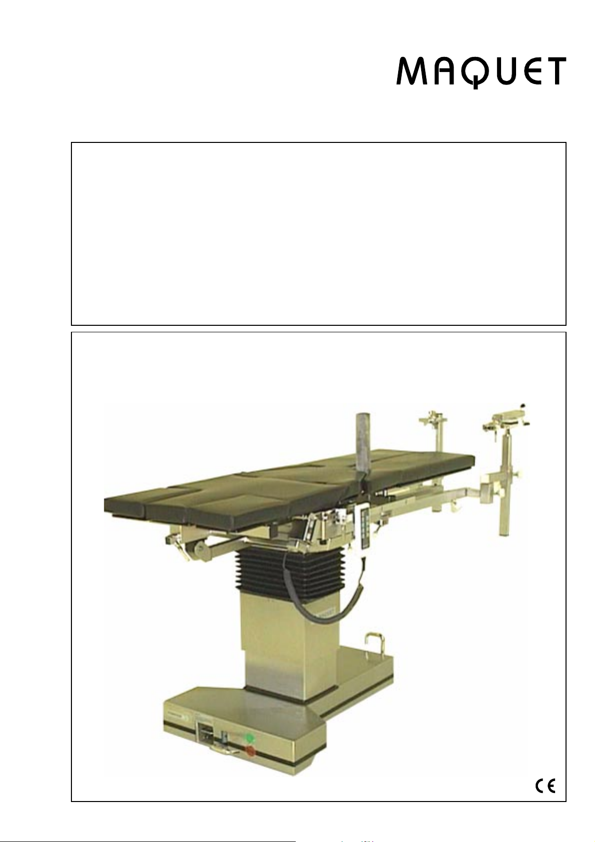
1425.01A/BORTHOSTAR II
Operating instructions
Mobile operating
and extension table
for:
traumatology
orthopaedics
spinal surgery
Englisch
GA142501GB03
Page 2
1425.01A/B ORTHOSTAR II
32
27
2
GA142501GB03
Page 3

1425.01A/B ORTHOSTAR II
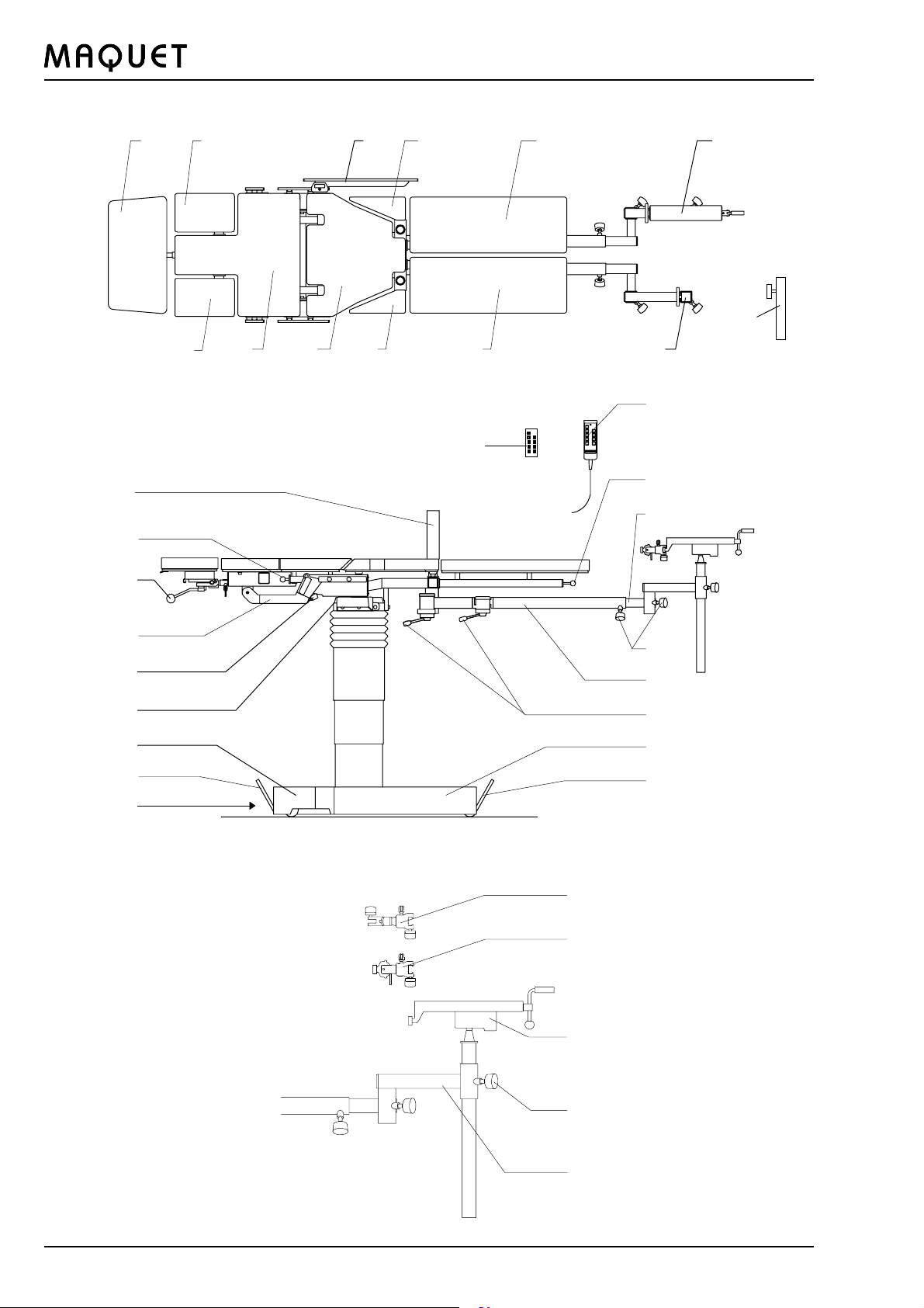
Pictorial guide
1 Head rest
2 Shoulder segment, left
3 Shoulder segment, right
4 Back plate
5 Seat plate
6 Side rail elongation
7 Triangular buttock support, left
8 Triangular buttock support, right
9 Leg plate, left
10 Leg plate, right
11 Countertraction post for neck of femur
12 Quick-release catch
13 Clamping lever
14 Supporting arm
15 Rocking lever
16 Pin for potential equalization (beneath the table top)
17 Rear base cover
18 Pedal
19 Supply cord on cable reel in the base
20 Pedal
21 Front base cover
22 Eccentric clamping lever
23 Traction bar
24 Handle screw
25 Telescopic bars
26 Quick-release catch for leg plates
27 Cable-connected hand control or IR hand control with charging station
28 Rotation and traction stirrup clamp
29 Rotation-tilt clamp
30 Screw tension device
31 Bar elongation
32 Foot plate support
GA142501GB03
3
Page 4

1425.01A/B ORTHOSTAR II
Contents:
Pictorial guide
I. Safety
II. Summary of safety precautions
III. General description
1. General description
2. Displacing / locking the operating table
3. Control of electrically controlled,
hydraulically powered motions
IV. Use of the operating table
1. Potential equalization
2. Mains operation
3. Battery-powered operation
4. Explosion protection
V. Table top components
1. Removing the back plate
2. Mounting sockets at the supporting frame
3. Leg plates
4. Triangular buttock supports
5. Traction bars
6. Padding
VI. Accessories
VII. Special accessory units
VIII. Removing the back plate
IX. Hazard of accident and injury
Accessories for Morbus Bechterew operations
Page
2 - 3
5
6
7 - 10
7
7
8
11
11
11
11
11
12
12
12
12
13
13
13
14 - 19
20
21
22
23
X. Care and maintenance
XI. Patient positioning using accessories
XII. List of accessories
XIII. Technical data
XIV. Spare part supply see spare parts list 9 491 320
4
24 - 25
26 - 34
35 - 36
37
38
GA142501GB03
Page 5
1425.01A/B ORTHOSTAR II
I. Safety
Important notes on these operating instructions:
Please read these operating instructions completely and carefully before using the unit. They were provided to
familiarize you with the features and correct use of the ORTHOSTAR II. Be sure to always follow the instructions
contained herein.
Store these instructions in a location near the equipment so that they will be available for ready reference.
We have used the following symbols to identify important notes in these instructions:
This symbol identifies information which is critical to safety as described in the international standard
applicable to the field of medicine.
è An arrow is placed in front of all information which is important to trouble-free operation of the system.
Intended use of an operating table
The operating tables sold by the MAQUET company are solely intended for medical treatment of humans. The
operator must be instructed in the correct use of the equipment. The equipment should be located in an area that
adheres to the current valid standards and guidelines. An absolute prerequisite for the use of the equipment is its
correct assembly and maintenance.
è For use the operating-room table has to be covered with clothes according to the established hygienic standards.
Fundamental safety aspects
l Any other use of the operating table, e.g. as a lifting platform, for material transport, as a rest rest platform, etc.
is considered not in accordance with the intended purpose.
Intended use
The operating table is intended for
l Positioning the patient during the operation incl. the preparatory and postoperative phases
l For transport of the patient inside the surgical department, e.g. from the patient transfer unit to the operating room
and vice versa.
This mobile operating table satisfies the requirements of the standard which is applicable internationally, IEC
601-1 (EN60601-1), corresponding to DIN VDE Standard 0750, Part 1. The operating table may be used only in
rooms where the installation technology satisfies the requirements of DIN 0107 or an equivalent national standard.
The ORTHOSTAR II operating table may be operated only by persons who have been instructed in the correct use
of the equipment. This familiarization by MAQUET was confirmed in an acceptance log.
CLASSIFIED BY UNDERWRITERS LABORATORIES INC: WITH RESPECT TO ELECTRIC SHOCK;
FIRE AND MECHANICAL HAZARDS ONLY IN ACCORDANCE WITH UL 2601-1
Whenever maintenance work is required, remember that the MAQUET Service Department is always the right
address in terms of quality and maintaining guarantee protection. You will certainly understand that MAQUET can
assume responsibility for the safe operation of your operating table only if maintenance, repairs, modifications, etc.
are carried out either by our service department or by a firm expressly authorized to do this work and only if the
unit has been utilized in full compliance with the operating instructions.
GA142501GB03
5
Page 6
1425.01A/B ORTHOSTAR II
II. Summary of safety precautions
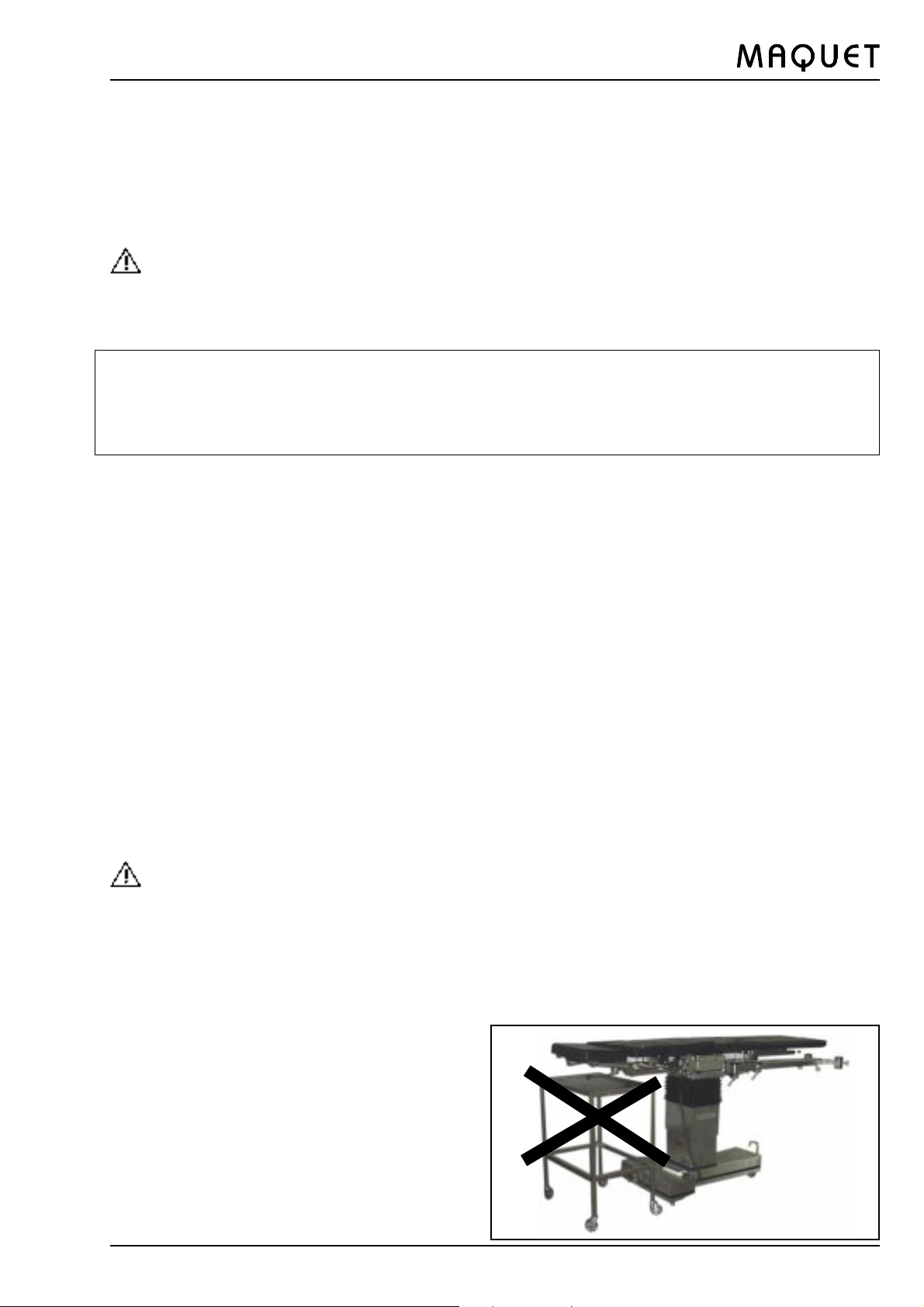
Pinch points are created during certain table top adjustments. Do not reach under the back plate or
attached accessory components and the joints.
The operator has to ensure that the location of the operating table is horizontal and safe.
The nursing staff must ensure that the patients are positioned and monitored so as to prevent compromising
respiration, nerve pathways or circulation.
Displacement of the operating table with patients weighing up to 135 kg (300 lb.) is allowed only up to a
table top height of 0.9 m (35.4 inches).
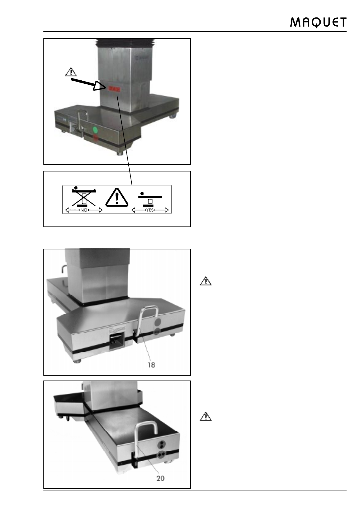
Note: The warning plate at the column must not be visible (Fig. A, page 7).
If the table top components contact an obstacle during an adjustment procedure, the table may tip. Remove
possible obstacles before lowering the operating table or individual table top components.
Lock the operating table when transferring the patient.
The operating table must not be operated from the mains in the presence of flammable anaesthetics.
Electrically conductive properties must be monitored by trained service personnel. Trained service personnel
must perform subsequent routine testing at least once a year.
When installing operating table accessories, check for correct attachment and tighten securely. Do not use
worn or damaged accessories. Check installation before using any accessory.
Unexpected table movement with a patient who is not secured could cause patient injury. The patient must
be secured to the operating table in accordance with the specific requirements, using the appropriate
accessories such as body strap, lateral supports, etc.
6
GA142501GB03
Page 7
1425.01A/B ORTHOSTAR II
Bild A
III. General description
1. General description
The ORTHOSTAR II 1425.01 is a mobile operating
table for traumatology, orthopaedics, spinal surgery
and shoulder operations.
The table top is divided into 8 sections (9 sections
including head rest to choice) and provided with
electrically controlled and hydraulically powered
adjustment functions for height, lateral tilt,
Trendelenburg / reverse Trendelenburg, and at the
back section.
Guide rails beneath the seat plate allow for X-ray film
cassette insertion from the sides. The side rails are
provided for fitting accessories.
The operating table is powered by batteries or mains
operated.
The batteries are recharged with a built-in battery
charger. The charge level of the batteries is indicated
by a luminous diode. Using an 0-position key, the
Trendelenburg and lateral tilt adjustments may be
reset and the table top returned to the horizontal
position. A pedal is used to lock and release the
operating table for travel.
According to IEC 601-1, the table is built for safe
è
handling of patients weighing up to 135 kg. If heavier
loading is to be expected, consult the manufacturer.
The operating table shall be equipped only with
MAQUET accessories (observe the operating
instructions!). Accessories made by other
manufacturers shall not be used without express
approval by MAQUET and must be particularly carefully
examined to ensure that they do not represent a
hazard to the patient, the personnel, or the operating
table.
When a patient is lying on the operating table, the
pedals for unlocking the base may be actuated
only when the warning plates are no longer visible
(Fig. A).
è Note:
All surgical procedures are permissible on the
locked operating table up to a patient weight of
135 kg (300 lb.).
2. Displacing / locking the operating table
è Always lock the operating table in position using
the pedals (18) and (20) before setting up the
patient position and during the operation.
For longitudinal displacement of the operating table,
l push the two pedals (18) and (20) upward
Displacement of the operating table with patients
weighing up to 135 kg (300 lb.) is allowed only up
to a table top height of 0.9 m (35.4 inches).
Note: The warning plate at the column must not
be visible (Fig. A).
For transverse displacement,
l push pedal (20) downward and
l pedal (18) upwar
For locking the operating table
l push pedal (20) upward and pedal (18) downward.
GA142501GB03
7
Page 8
1425.01A/B ORTHOSTAR II
3. Control of electrically controlled, hydraulically
powered motions
Depending on the customers requirements, the
operating table motions may be controlled by the
following three elements:
l Cable-connected hand control
l IR hand control
l Foot switch (only for the table top up/down and
Trendelenburg/reverse Trendelenburg functions.
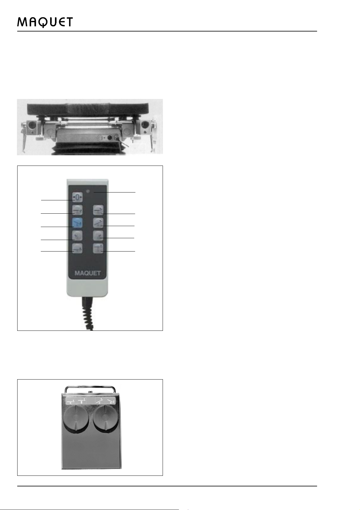
3.1 Cable-connected hand control
Once it has been removed from its packaging, the
plug for the cable-connected hand control is
connected at one of the two sockets (33) at the
column head. The operating table can then be
adjusted on battery power.
n
a
b
d
f
h
c
e
g
i
The column is equipped with two sockets for
simultaneous connection of the cable-connected
hand control and the foot switch.
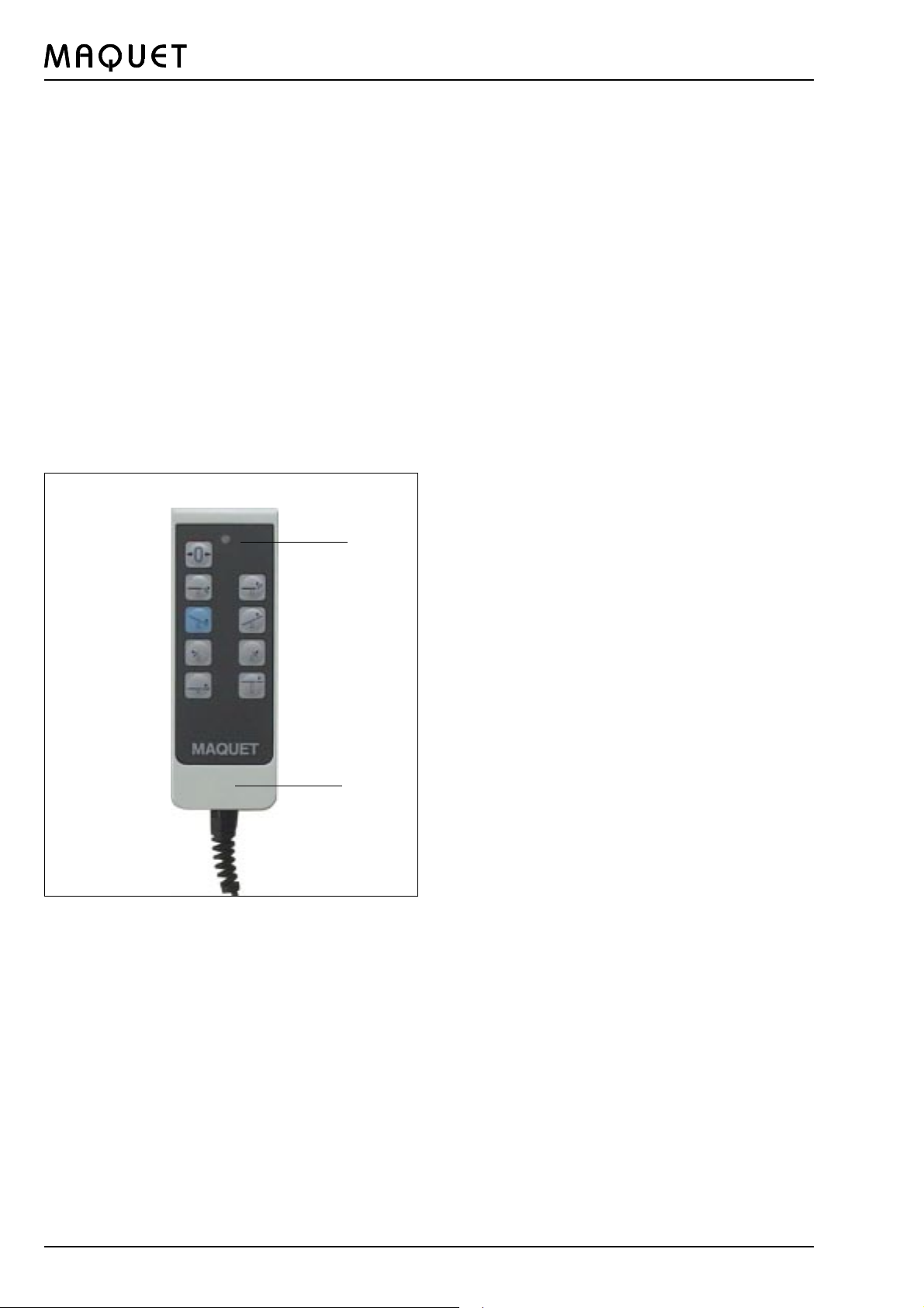
3.2 Functions
Press the appropriate function key to invoke the desired
adjustment function.
a Automatic 0-position feature
b Back plate downward
c Back plate upward
d Trendelenburg position
e Reverse Trendelenburg position
f Lateral tilt to left
g Lateral tilt to right
h Table top downward
j Table top upward
n Capacity indicator
3.3 Foot switch control
The foot switch (separate ref. no. 1009.79-B) is also
connected to one of the two sockets at the column
head. Now the electrically controlled, hydraulically
driven functions up/down and Trendelenburg/reverse
Trendelenburg can be operated by either the foot
switch, the cable-connected hand control or the IR
hand control.
èNote:
If functions are initiated simultaneously via foot
switch and hand control, each function of the
system will be stopped instantly and will be
resumed only when one of the control elements has
been released.
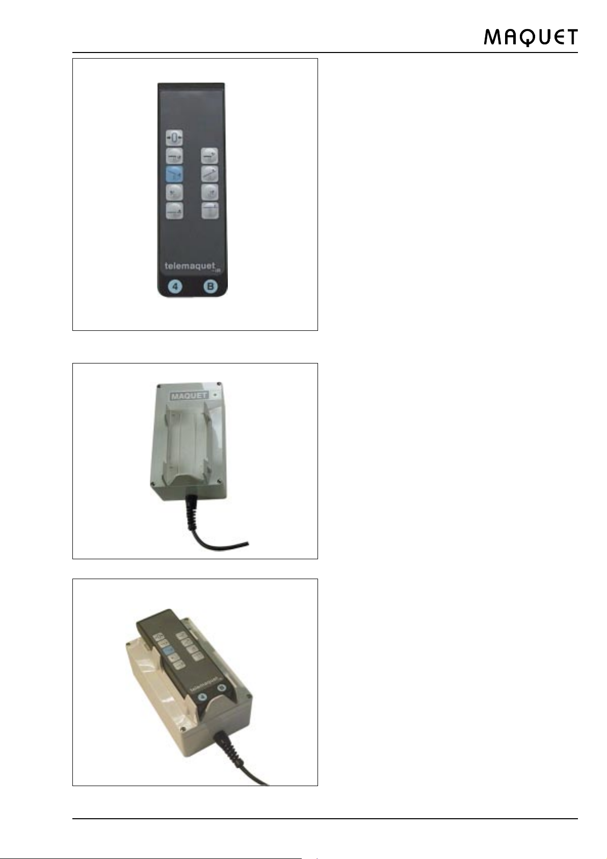
3.3a Infrared remote control
If desired, the table may be equipped with an IR
remote control. The arrangement of the function keys
for the adjustments of the operating table is the same
as on the cable-connected hand control.
If the operating table is equipped with an infrared
remote control, it differs from the version with the
cable-connected hand control in the following
characteristics:
l Cordless hand control
l Additional charging station with supply cable for IR
hand control
l Capacity indicator for battery capacity of the
operating table at the column head
l Additional acoustic signals of the operating table
and the IR hand control in particular use situations.
8
GA142501GB03
Page 9
1425.01A/B ORTHOSTAR II
è Note
The transmission power of the IR hand control is
sufficient to be able to adjust the operating table
even from a greater distance and with the
operating table draped. If the operating table does
not respond to the command even though the
function key is completely depressed, either reaim
the hand control or move to a slightly different
transmission position. In such cases the sensor
at the column is being blocked by a person.
3.4 IR system code
Each operating table and its IR hand control are
identified with the same codes. The encoding is
undertaken by authorized personnel.
The operating table and its hand control are
marked
with blue labels. The label is located
l at the lower end of the hand control
l at the base of the operating table near the supply
cable.
The IR system code is identified by a numeral from
0 to 9 or a letter from A to F.
Examples of possible IR system codes:
4B
C2
DA
è Note
The order of the numerals and letters is significant
here; IR system code 4 B is not equivalent with B
4, for instance.
The operating table can, of course, be used at any
time by connecting a cable-connected hand
control; here the IR system code is of no
significance.
3.5 Charging station
The charging station of the IR hand control is used for
recharging the battery in the hand control. The charging
station can be mounted on the wall near a power
socket; however, it does not necessarily have to be
mounted at all.
To recharge the battery in the IR hand control,
connect the charging station to the mains via supply
cable. The green indicator lights up.
Insert the hand control in the charging station as
follows:
GA142501GB03
l Hold the hand control so that the keypad is
visible, in the position for normal use
l the 0-position key is at the top
l the lower, narrow end of the hand control is in
contact with the lower edge of the holder.
9
Page 10
27
1425.01A/B ORTHOSTAR II
The battery in the IR hand control has sufficient
capacity to control adjustments of the operating table
for several days. We nonetheless recommend that the
hand control be stored in the charging station in the
evening so that the battery will be recharged overnight.
3.6 Battery charge level
The capacity of the batteries in the operating table and
the IR hand control is indicated by optical and acoustic
signals.
a) IR hand control
l A continuous tone will be sounded when one of the
function keys is pressed (the adjustment motion is
being executed). The capacity of the battery in the
hand control has dropped to approx. 10 %. Insert the
hand control in the charging station once the
adjustment motion has been completed.
b) Operating table
The battery charge level is indicated optically by the
luminous diode n.
When using a cable-connected hand control, the
luminous diode is integrated in the hand control.
n
When using an operating table with an IR hand
control, the luminous diode is located at the column
head.
Charging capacity
green continuous light at n:
Charging condition 100 30 % = good
Red continuous light at n:
Charging condition 30 10 % = still sufficient
Red intermittent light at n:
Charging condition less than 10 % = very low;
The batteries should urgently be recharged on
completion of the surgical intervention.
èNote
In addition to the luminous diode blinking red, this
charging condition is also indicated by an
intermittent acoustic signal for operating tables with
IR hand control.
Green intermittent light at n:
The operating table has been connected to the mains
supply. The batteries are being recharged; adjustments
can be made.
The operating table has been connected to the mains
supply. The batteries are being recharged; adjustments
can be made.
No signal at n:
The maximum discharge limit has been reached.
The electronics have shut down the unit to avoid
deep discharge which would damage the batteries.
The batteries must be charged.
10
Charging the batteries:
To recharge the batteries, connect the operating table
via the supply cable to the mains supply. The full
charging capacity is attained after a charging time of
approx. 15 hours. Overcharging is avoided by an
electronic power control. We recommend recharging
the batteries overnight or during the weekends.
GA142501GB03
Page 11
1425.01A/B ORTHOSTAR II
IV. Use of the operating table
1. Potential equalization
Connect the potential equalization pin (16) with cable to
a potential equalization point in the operating room (as
per VDE Electrical Standard 0107 or the corresponding
national codes).
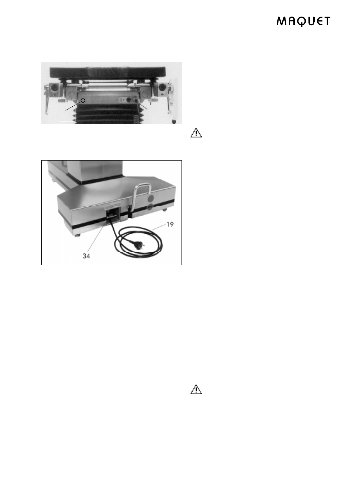
2. Mains operation
Use the cable (19) to connect the operating table to
the mains supply. To do so, pull the supply cable out of
the opening in the base (cable length approx. 4.5 m).
The separation of the OR-table from the mains is
made by the power plug.
èNote
Damaged mains cables must be replaced!
When pressing the lever (34) upward, the supply cable
is automatically wound on the cable reel inside.
3. Battery-powered operation
Unplug the operating table. At full charge,
the batteries will power the operating table
for several weeks, depending on the frequency
with which the adjustments are made.
èNote
Operating the table under battery power is always
to be given preference to operation from the mains
supply.
4. Explosion protection
When running on the integral batteries only with
no connection to the mains supply, the operating
table satisfies the requirements of Class M for the
anaesthetic test. It may be used in areas subject
to explosion hazard, Zone M.
When the operating table is connected to the
mains supply, it is not suitable for use in areas
subject to explosion hazard (AP-M).
Please refer to your national safety regulations.
GA142501GB03
Attention
To prevent oil leakage after the bleed screw has
been installed, do not tilt the operating table through
more than 25°.
11
Page 12
1425.01A/B ORTHOSTAR II
V. Table top components
1. Back plate (4)
The Orthostar II is equipped with a back plate (4) which
can be raised from the horizontal position under motor
power, using the hand control modules (see Section 3,
from page 8).
For shoulder operations, the shoulder segment (2) or
(3) may be removed by pulling off.
To attach the shoulder sections (2/3), insert them in the
square tube of the back plate and apply gentle pressure
to snap them in position. They will engage
automatically.
The entire back plate may be removed from the
operating table in order to attach other accessory units
for operations on the spinal column.
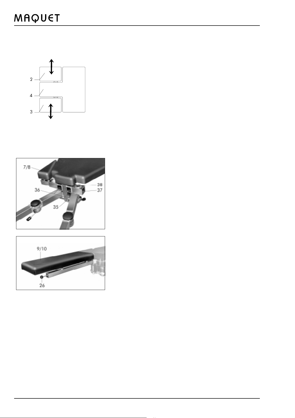
2. Mounting sockets at the supporting frame
The following mounting sockets are located at the
supporting frame (35) in the foot side area of the seat
plate:
l The square sockets (36) pointing towards the foot
end are used to attach the leg plates (9/10).
l The square sockets at the sides (37) are used to
attach the triangular buttock supports (7/8) and
various accessories.
l The vertical round sockets (38) are used to attach
the countertraction posts (see Chapter Basic
accessories)
3. Leg plates
To attach the leg plates (9/10), pull on the quickrelease catch (26) and insert the leg plate in the
square socket (36) up to the stop with the quickrelease catch (26) still being pulled on. The leg
plates will automatically be fixed in position as soon
as the catch (26) is released. To pull out the leg
plate, first pull on the quick-release catch (26) and
remove the leg plate with the catch (26) still being
pulled on.
12
GA142501GB03
Page 13

1425.01A/B ORTHOSTAR II
4. Triangular buttock supports
The triangular buttock supports (7/8) are
complementary parts of the table top. Like the leg
plates, they are used in the preparatory phase and
will be removed during the operation. To remove
them, pull them out of the sockets (37) to the side.
To attach the triangular buttock supports, place the
square tube to the socket (37) and press gently into
place with the ball of the thumb. It is locked
automatically.
5. Traction bars
Two traction bars are mounted on the supporting frame.
These bars (23) swivel in two swivel joints so that they
can be swung horizontally. The swivel joints nearer the
head are used to swing the entire traction bar, the ones
nearer the foot to adjust the angle of the bar. These
swivel joints make it possible to position the traction
bars during the operation so that they will not interfere
with using the image intensifier to examine the patients
extremities.
To adjust the traction bars, release completely the
clamping levers (22) for the appropriate swivel joint by
moving the lever horizontally. The directions of rotation
for releasing or tightening the clamping levers are shown
on the black covers on the swivel joints.
6. Padding
The table top consists of table top plates with pads
which are attached by means of Velcro straps.
èNote
l To clean the pads, remove them from the table top
plates.
l When re-placing them, take care that the soft bands
of the Velcro straps are completely dry.
GA142501GB03
13
Page 14

1002.86B0
13
1425.01A/B ORTHOSTAR II
VI. Accessories
1. Basic accessories
1
In addition to the leg plates, the extension table tops
are provided with the following basic equipment:
1.1 Head rest (to choice, 1002.81D0 or 1002.86 B0)
Mount the head rest (1) by inserting the square rod
in the mounting socket at the head end of the table
and tightening down the set screw.
To adjust the head rest, turn the clamping lever (13)
to the left and move the head rest to the desired
angle. Move the locking lever back to the right to
lock the head rest in position.
1.2 Telescopic bars
The telescopic bars (25) are supplied in two
different lengths.
Identification:
Long telescopic bar: with white end cap
Short telescopic bar: with black cap
The telescopic bars are inserted in the traction bars
(23) in preparation for mounting additional accessories;
the handle screws of the traction bars are used to fix
the telescopic bars at the required length.
è Note:
To ensure secure fixing of the telescopic bars they
must be inserted at least far enough into the
traction bars that the red mark is no longer visible.
14
GA142501GB03
Page 15

1425.01A/B ORTHOSTAR II
31
25
30
1.3 Bar elongations
The bar elongations (31) are inserted in the
telescopic bars (25) where additional length is
required; the bar elongations are fixed with the
handle screw. If turned through 180° and inserted,
they may be used where required to shorten the
telescopic bars.
1.4 Screw tension device 1003.37
The screw tension device (30) is used to adjust the
traction tension applied during the operation. The
supporting bar (30a) is inserted in the square
socket at the end of the telescopic bar and fixed at
the desired height by tightening the handle screw.
1003.37
1003.49
7/8
30b
30a
The screw tension device (30) is permanently joined
with the supporting bar (30a) by means of a balland-socket joint. Once the clamping lever (30b) has
been released, the screw tension device will swivel
freely on the ball. Swing the clamping lever (30b)
upward completely to release. To lock the screw
tension device in position, move the clamping lever
(30b) downward to the stop (the lever will then be
horizontal).
1.5 Foot plate support 1003.49
The foot plate support is also inserted in the socket
of the telescopic bar and used, in conjunction with
additional accessories (e.g. sole plate), to position
the sound leg of the patient.
1.6 Countertraction post for neck of femur
The countertraction post (11) is inserted in the
mounting socket (38) after removing the appropriate
buttock support (7/8). The countertraction post
serves to resist the traction applied during the
operation to the extremity affected. It will then be
located on the side corresponding to the fracture, in
the patients perineal area.
GA142501GB03
38
15
Page 16

1003.34
29
28
1425.01A/B ORTHOSTAR II
1.7 Rotation-tilt clamp 1003.34
The rotation-tilt clamp (28) serves to attach the foot
plates (to be ordered separately, ref. no. 1001.87)
to the screw tension device. The clamp is slid onto
the side rail at the screw tension device and is then
secured with the handle screw.
After loosening the upper locking handle, the side
rail may be rotated through 360°. Loosening the
lateral locking handle will make it possible to tip the
mounting rail section to accept the foot plate.
1.8 Rotation and traction stirrup clamp 1003.35
The rotation and traction stirrup clamp (29) serves
to attach to the screw tension device the traction
stirrups which are used for wire traction purposes.
The clamp is slid onto the mounting rail section at
the screw tension device and secured with the
handle screw. After loosening the locking handle,
the traction stirrup can be rotated through 360°.
After loosening the handle screw, the traction
stirrup may be inserted in the socket and secured
in position. The adjustment screws are provided for
fine positioning and exact fixing of the traction
stirrup.
1003.35
1004.91A0
1.9 Side rail elongation 1004.91A0
The side rail elongation (6) is mounted on the side
near the seat plate wherever accessory
6
components have to be attached at the lower end of
the seat plate (a Goepel knee crutch to support the
sound leg, for instance).
2. Optional accessories
The side rail elongation (6) is mounted on the side
near the seat plate wherever accessory
components have to be attached at the lower end of
the seat plate (a Goepel knee crutch to support the
sound leg, for instance).
2. Optional accessories
In addition to the basic accessories, there is
available a number of supplementary components
which may be utilized in accordance with the
requirements of the operation or the preferred
operating techniques.
2.1 Countertraction post for interlocking nailing
1004.90B0
This countertraction post is used instead of the
post for neck of femur (11) when treating femur
fractures with the patient in the supine position (and
also for interlocking nailing technique).
1004.90B0
16
The countertraction post for interlocking nailing is
inserted in the socket (38) at the supporting frame
after removing the buttock support (7/8) and the leg
plates (9/10) on the side corresponding to the
fracture.
GA142501GB03
Page 17

1425.01A/B ORTHOSTAR II
b
d
38
37
1004.85B0
c
40
37
2.2 Countertraction post for femur 1004.85B0
a
This countertraction post is used when treating
femur fractures with the patient in the lateral
position. The positioning plate (d) is supplied with
the 1004.85 countertraction post.
After removing the buttock support (7/8), the
countertraction post is inserted in the socket (37)
at the supporting frame and secured in the socket
(38) with the catch. The upper section of the
countertraction post (a) and the perineal bow (b)
may be removed by lifting it off. The perineal bow
(b) can be shifted through 180° and mounted for
use at the right or left of the table top. The vertical
spacing between the table top and the perineal bow
is adjusted with the hand crank (c).
The positioning plate (d) is inserted in the sockets
(37) after removing the leg plates (9/10).
2.3 Perineal support 1004.89
The perineal support is also used when treating femur
fractures with the patient in the lateral position. It
serves to absorb the traction tension applied to the
extremity being worked on.
The holder (a) is inserted in the socket (37) at the
supporting frame (40) after removing the buttock
support (7/8). Insert the perineal support and use the
handle screw to fix at the desired height.
1004.89
D
2.4 Countertraction post for tibia and fibula
a
E
F
1003.50A0
This countertraction post is used when operating on
lower leg fractures.
After removing the buttock support (7/8), insert the
countertraction post in the socket (37) at the
supporting frame, securing it with the catch in the
socket (38). The countertraction post (a) and the
telescopic bar (b) can be lifted off after loosening
the appropriate handle screw.
The countertraction post (a) can be shifted
through 180° and mounted for use at the right or left
of the table top. The vertical spacing between the
table top and the countertraction post (a) is
adjusted after loosening the handle screw (c).
After opening the eccentric safety lever (d) the
countertraction post (a) can be swivelled to the
front.
Attention:
Hold the countertraction post at the telescopic bar
(b) before opening the eccentric lever and until the
eccentric lever (d) is locked again!
[
1003.50A
GA142501GB03
G
17
Page 18

1425.01A/B ORTHOSTAR II
To set up the traction exerted at a downward
angle, the countertraction post for tibia and fibula
can be swivelled via the gear rim: Press the safety
button (x) and open the eccentric lever (d). Swivel
the countertraction post as desired and tighten the
eccentric lever (d).
Attention
D
E
F
[
G
With extension accessories fixed in the telescopic
bar, the countertraction post may drop
automatically! Therefore, always support the
countertraction post with the free hand when
making adjustments.
1003.50A0
1004.93B0
1003.51
2.5 Condyle fixation 1004.93-B0
The condyle fixation can be used to secure the
patients knee exactly on the tibia countertraction
post while operating on lower leg fractures and thus
will help to avoid rotary alignment errors. The swivel
holders are bolted at the right and left on the
countertraction ratchet disks. Height adjustments
to suit the patients anatomy are made possible by
the eccentric attachment of the pressure plates to
the horizontal holder bars.
2.6 Horizontal guiding bar 1003.51
The horizontal guiding bar may be used to correct
the direction of traction at right angles to the
longitudinal axis (e.g. tibia fractures). To use the
guiding bar, attach the telescopic bar shifted
through 90° and tighten the guiding bar in the
socket, using the handle screw. The square socket
of the horizontal guiding bar is used exclusively to
attach the screw tension device.
2.7 Pelvis support plate 1003.52
The pelvis support plate can be used for procedures
with the countertraction bar centred along the
longitudinal axis of the table top., e.g. bilateral hip
procedures (e.g. corrective osteotomy).
To attach the pelvis support plate, remove the leg plates
from the table top and insert the pelvis support plate in
the square sockets for the leg plates.
The patients legs are positioned over the traction bars
using the basic accessories.
1003.52
18
GA142501GB03
Page 19

1425.01A/B ORTHOSTAR II
1004.86
1004.87
30
a
x
c
b
23
2.8 Universal support 1004.86
The universal support is used to position the sound
extremity. It is mounted at the guide bushing (a) on
the supporting bar for the screw tension device (30)
and fixed with a handle screw. The horizontal
guiding bar (b) is pivoted and the extension length
variable. The upholstered support can be moved on
the ball joint at the vertical bar after loosening the
appropriate handle screw (x).
2.9 Leg plate support 1004.87
The leg plate supports are used whenever the leg
plate (9/10) is to be attached to the traction bar
(23). Attach the leg plate support to the traction bar
and fix with the handle screw. Insert the leg plate in
the upper square socket. To do so, pull the quickrelease catches for the leg plate (26) towards to
foot end.
2.10 Clamp with side rail 1004.88
The clamp with side rail is used to mount
accessory components which are to be attached
to one of the traction bars. Use the handle screw
to fix the clamp with side rail to the traction bar.
1004.88
1001.87
2.11 Foot plate
The foot plate serves to secure the patients
extremity. It is most useful to attach it to the
rotation-tilt clamp (28) (see page 2) at the screw
tension device to make for exact adjustment in
regard to angle and rotation. The foot plate is
available in two sizes:
For adults
ref. no. 1001.87
For children
ref. no. 1001.90
2.12 Traction boots
For adults
ref. no. 1001.88
For children
ref. no. 1001.91
1004.41
GA142501GB03
2.13 Sole plate 1004.41
Use the 1001.41 sole plate as an alternative to the
combination of the foot plate and the traction boot.
The patients feet are fixed using gauze, tape or
the like.
19
Page 20

1425.01A/B ORTHOSTAR II
VII. Special accessory units
The ORTHOSTAR II can be equipped with special
accessory units (separate ref. nos.) for operations on
the spinal column.
For this purpose the entire back plate (4) can be
removed from the operating table, allowing to use the
electrically controlled, hydraulically driven interface for
these accessory units.
For interventions at the spinal column the shoulder
sections (2) and (3) can be removed by pulling them off
to the side.
Check to ensure that the bars are inserted up to
the stop and that the balls are fully engaged in the
mounts.
1. Positioning unit for operations on the spinal
column 1007.03A0 with the patient in the
genucubital position
Remove the entire back plate (4) from the
operating table to attach these accessory units;
mount and use 1007.03A0 as described in the
separate Operating Instructions 9 491 472 401
l Trolley 1007.07A0
l Bracket with lateral supports 1007.05A0
2. Pair of bars with skids 1007.08A0 for
Morbus Bechterew operations
Remove the entire back plate (4) from the
operating table to attach these accessory units;
mount and use 1007.08A0 as described in the
separate Operating Instructions 9 491 472 401.
l Sternum support 1007.10A0
l Thorax support 1007.11A0
l Guiding roller for head-side traction 1007.12A
20
GA142501GB03
Page 21

1425.01A/B ORTHOSTAR II
VIII. Removing the back plate
The back plate may be removed for cleaning or
attachment of other accessory components.
To remove the back plate, proceed as follows:
l Loosen the locking handle at the back plate (4) and
pull the head rest (1) out of the square rod.
l Remove the shoulder segments (2/3) by pulling them
off to the side.
l Pull the quick-release catches (12) at the back plate
(4) simultaneously towards the rear to release the
back plate.
Now the back plate is released and may be removed by
lifting it off in the direction of the arrow.
l To remove the supporting arm (14), pull the rocking
levers (15) towards the head end and pull out the
supporting arm.
l To attach the supporting arm (14), pull the rocking
levers (15) towards the head end and insert the rods
to the full depth of the mounting holes (45).
To attach the back plate, proceed as follows:
l Hang the clamps (43) of the back plate into the
openings (44).
l Pull the two quick-release catches (12)
simultaneously to allow the pins to engage in the
openings.
GA142501GB03
21
Page 22

1425.01A/B ORTHOSTAR II
IX. Hazard of accident and injury
Caution hazard of accident and injury!
When the back plate is lowered, never reach into
this area and take care that there are no objects in
the area near the right and left hinged sockets (46)
and the right and left seat rails (47).
46
46
47
23
22
Caution hazard of accident and injury!
Danger of pinching between the traction bars (23)
and the hinged sockets (46) on either side
when swivelling the traction bars completely
towards the head end.
46
23
GA142501GB03
Page 23

1425.01A/B ORTHOSTAR II
1007.08A0
Accessories for Morbus Bechterew operations
2.1 Pair of bars with skids 1007.08A0
For interventions at the spinal column to treat, for
example, scoliosis of Morbus Bechterew. Suitable
for operating tables 1130 and 1425, for instance.
Pair of bars for mounting the skids which slide in
the longitudinal direction, for attachment of head
and arm positioning accessories and the sternum
support 1007.10-A0.
2.2 Sternum support 1007.10A0
Transverse, radiotranslucent unit for attachment to
the sliding skids of the 1007.08-A0; the patients
thorax is supported by an attached, pivoted
support plate with a foam pad measuring 300 x
175 mm, 100 mm diam. padded roll or 50 mm
diam. padded roll.
1007.10A0
1007.11A0
2.3 Thorax support 1007.11-A0
Suitable for 1007.08-A0; can be used instead of
the sternum support 1007.10A0 during
interventions in the lumbar vertebral area;
radiotranslucent with foam pad, electrically
conductive cover.
2.4 Guiding roller for head-side traction 1007.12-A0
In combination with 1002.7000; mounted on side rail
piece (e.g. on 1002.64A0) on 1007.08A0, with
longitudinal and height adjustment.
1007.12A0
GA142501GB03
23
Page 24

1425.01A/B ORTHOSTAR II
X. Care Maintenance
Electrically conductive properties must be monitored by trained service personnel. Trained service
personnel must perform subsequent routine testing at least once a year.
A mildly alkaline all-purpose cleaning agent (soap solution) is recommended for cleaning the operating table
and accessories. Further, the cleaning agent should
contain surfactants and phosphates as the active
cleaning agents. Use the cleaning agent in concentrated form if the surfaces are extremely soiled. This
will, however, make it necessary to rinse them afterwards with clear water. Then use a dry cloth to remove
any water which may have collected.
We recommend to cover the table top with sterile
sheets when not in use.
Surface disinfectants which contain neither chlorine
nor compounds which would liberate chlorine are
suitable for sanitizing. We suggest using a standard
surface disinfectant in an aqueous solution to disinfect
the operating table upholstery. Please observe the
manufacturers instructions for use and disinfect
manually.
Hand sanitizing compounds are not suitable for
disinfecting the operating table padding since they
usually contain alcohol or compounds of alcohol.
Disinfection agents containing alcohol must not be
used on the padding since excess exposure to alcohol
(i.e. collections of liquids containing alcohol and
remaining in contact with the surface for longer than 5
minutes) could damage the finish of the padding. The
potential hazard of forming explosive mixtures also
precludes using agents containing alcohol for surface
disinfection.
It is for this reason that we recommend using an
aldehyde-based disinfectant to clean the surfaces.
Disinfection of the castors:
l Raise the operating table to the highest position,
function key (j).
l Grip the rear cover (17) with both hands from the
sides and pull it upwards.
l Slightly lift the front cover (21) at the front end and
pull it forward.
l Unscrew the castor covers (47/48); the castors are
now accessible for disinfection.
l Re-assemble the covers of the castors
l Slide the inclined front cover (21) from the front onto
the T-base and press firmly into place.
l Slide the rear base cover (17) from above onto the T-
base and take care that the edges of the front cover
are covered at the same time.
24
GA142501GB03
Page 25

1425.01A/B ORTHOSTAR II
Notes:
èIf the lateral tilt and Trendelenburg/reverse
Trendelenburg functions have not been used for a
longer time, play may be encountered in the
universal joint suspension.
Remedy:
Operate both movements until the final stop is
reached, e.g. lateral tilt right/left or Trendelenburg /
reverse Trendelenburg position.
The hydraulic system should be serviced by
MAQUET Customer Service staff only.
èRegular recharging of the batteries, e.g. at night or
over the weekend, even if the battery indicator
(luminous diode n) indicates sufficient charge, will
extend battery life.
The operating table has to be serviced annually. Please
contact the MAQUET Customer Service (Service
Hotline see last page) or a local representative.
To conclude a maintenance contract, please contact:
MAQUET Aktiengesellschaft
P.O. Box 2162
D-76411 Rastatt
Phone + 49 7222 932-0
Fax + 49 7222 931-631
For maintenance outside Germany, please contact your
local representative.
If your operating table malfunctions, please contact
your MAQUET representative or the company itself.
Describing the symptoms and quoting the serial
number will help us solve your problem faster.
In case of malfunctions do not try to repair the table nor
to use force.
Environmental protection
l Do not throw old, damaged batteries to the normal
waste.
l Do not throw batteries into water or fire
l Remove the hydraulic oil before disposing of the
table.
l Dispose of electronic waste from the control unit and
the hand control modules in accordance with the
rules.
GA142501GB03
25
Page 26

1425.01A/B ORTHOSTAR II
XI. Patient positioning
General:
All the patient positions described below may be set up
by just a single person (except for the position for
nailing the femur in lateral position).
The extension accessories are mounted after
anaesthesia has been initiated with the patient in the
supine position on the table top. Only after patients
extremities have been placed in the approximate
position are the leg plates removed and the final
position set up (by adjusting the accessory
components).
èOnce the patient position is completed, check
to ensure that all eccentric levers and clamping
screws at the operating table and the accessories
are tightened down completely.
On completion of the surgical treatment, first attach the
leg plates, then release the feet / legs and remove the
accessory components.
HF surgery
Use of defibrillators and defibrillation
monitors
When using electrocautery units,
defibrillators, and defibrillation monitors, it is
important to follow the manufacturers
instructions. Disregard of safety precautions
can lead to serious incidents. If the patient
should come into contact with the metal parts
of the operating table or with accessories,
there is a danger of burns. This also applies if
the patient is lying on moist underlays or
sheets on the conductive operating table
pads!
26
GA142501GB03
Page 27

1425.01A/B ORTHOSTAR II
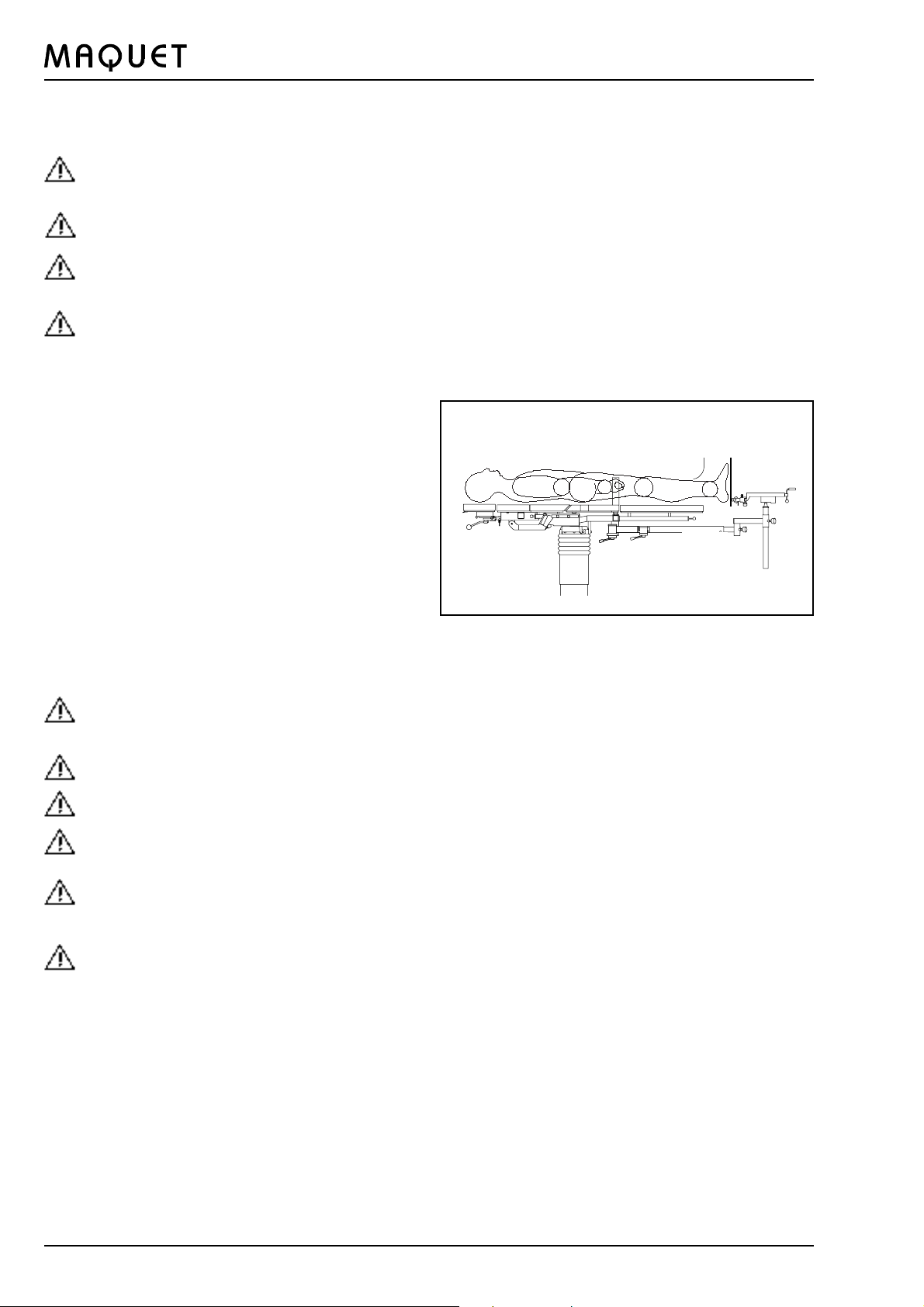
Patient positioning for nailing neck of
femur
I. Recommendations for positioning
l Patient in supine position
l with his legs straddled
l feet attached in traction boots with a slight inward
rotation
l perineum close to the countertraction post
In order to permit image intensifier control in vertical
a.p. view, it is recommended to tilt the operating table
at the side of the affected leg 15° to the unaffected leg.
The C-arm can be inserted from between the legs or
laterally from the head end, depending on the medical
indication.
II. Patient positioning
Accessories:
11 Countertraction post for neck of femur
25 Telescopic bars
30 Screw tension device
28 Rotation-tilt clamp
Foot plates 1001.87
Foot plate support (for the unaffected leg)
1003.49
23
11
l Bars and accessories to be adjusted according to
the illustration, to be fitted to the patient and secured
l The countertraction post has always to be inserted
on the side of the affected leg
l Remove the leg plates
l Adjust the C-arm for control in a.p. and lateral view
l Drape the patient
èNote:
On completion of the surgical treatment, first attach the
leg plates (9/10) (see page 20), then release the feet /
legs.
Remove the countertraction post (11)! Swivel the bars
(23) towards the head end.
GA142501GB03
27
Page 28

1425.01A/B ORTHOSTAR II
Positioning for nailing femur in lateral
position
I. Recommendations for positioning
l Patient in lateral position on his sound side
l The affected femur is placed over the perineal bow of
the countertraction post with the hip bent at approx.
right angles. For transcondyle wire extension the
lower leg is supported at an angle of approx. 80°
l Clamp the sound leg and stretch backwards as far
as possible until the C-arm can be swivelled in both
planes without trouble.
l C-arm between the patients legs.
II. Patient positioning
Accessories:
Countertraction post for femur 1004.84
25 Telescopic bars, for transcondyle extension,
the short telescopic bar is used as traction bar.
29 Rotation and traction stirrup clamp
28 Rotation-tilt clamp
30 Screw tension device
Foot plate 1001.87
Universal support 1004.86
Foot plate support 1003.49
l Adjust bars (23) and accessories as shown on the
photo.
l Remove leg plates (9/10) and insert positioning plate
a
b
d
(d)
l Move patient towards the foot end, place fractured
femur over the perineal bow (b), adjust the height using
the crank (c)
l Adapt bars and accessories to the patient and secure
them
l Adjust C-arm for a.p. and lateral view
l Drape the patient
èNote:
c
On completion of the surgical treatment
l move the patient towards the head end
l remove the positioning plate (d)
l attach leg plates (9/10), then release feet/legs
l remove countertraction post, swivel the bars towards
the head end.
28
GA142501GB03
Page 29

1425.01A/B ORTHOSTAR II
Positioning for nailing femur in supine
position, as well as for interlocking nailing
I. Recommendations for positioning
Patient in supine position with
l transcondyle Steinmann nail extension on the distal
femur fragment or
l over the stretched leg with foot plate The sound leg is
placed
l in the Goepel knee crutch and adjusted laterally
towards the head end or
l downward in half-vertical position until the second
femur permits the unobstructed control of the affected
femur by means of the image intensifier.
Proximal fracture:
l Extreme flexion of the patients body to the sound
side
l Traction in the axis of the leg without adduction
Distal fracture:
l Flexion of the patients body to the sound side
l Traction with extreme adduction
l The C-arm is placed in a contra-lateral position at
right angles to the affected extremity.
II. Patient positioning
Only one traction bar is necessary for this positioning.
Accessories:
Countertraction post for interlocking nailing
1004.90
25 Telescopic bar short for transcondyle
traction
25 Telescopic bar long for traction over the
stretched leg
30 Screw tension device
29 Rotation and traction stirrup clamp
6 Side rail elongation
Radial setting clamp 1003.23
Goepel knee crutch 1001.65
alternatively for traction over the stretched leg
(see photo below):
28 Rotation-tilt clamp
Universal support
Foot plate
l Adjust bars and accessories as shown on the photo,
adapt them to the patient and secure them.
l Adjust bars and accessories as shown on the photo,
adapt them to the patient and secure them.
l Drape the patient.
GA142501GB03
èNote:
On completion of the surgical treatment
l remove the countertraction post
l attach leg plates (9/10)
l then release feet/legs
6
l swivel the bar (23) towards the head end
29
Page 30

1425.01A/B ORTHOSTAR II
Positioning for nailing femur in lateral
position
I. Recommendations for positioning
l Patient in lateral position
l Extension with foot plate
l The affected extremity is placed horizontally over the
perineal support which is used instead of the
countertraction post.
l The sound leg is placed on a leg plate and is
abducted or in nearly parallel position to the affected
extremity in order to permit unobstructed access of
the C-arm in both planes
l C-arm approached in contra-lateral position at right
angles to the affected leg.
II. Patient positioning
Accessories:
Perineal support 1004.89
25 Telescopic bar long
30 Screw tension device
28 Rotation-tilt clamp
Foot plate 1001.87
Leg plate support 1004.87
1004.89
l Adjust bars and accessories as shown on the photo
l Equip traction bar (23) with leg plate support.
Leg plate (9) must be swivelled laterally.
l Insert perineal support, adjust its height to the
patient
l Insert perineal support, adjust its height to the
patient
l Remove the second leg plate (10)
l Adjust C-arm for a.p. and lateral view
l Drape the patient
èNote:
On completion of the surgical treatment
l Attach leg plate (9)
l Align second leg plate (10) in parallel position
l release the foot
l remove the perineal support
l swivel the bars towards the head end.
30
GA142501GB03
Page 31

1425.01A/B ORTHOSTAR II
$
Positioning for nailing tibia and fibula
I. Recommendations for positioning
l Patient in supine position with trans-calcaneal
Steinmann nail extension
l The sound leg is placed in the Goepel knee crutch
and adjusted laterally towards the head end
l The countertraction post must lie close to the lower
third of the thigh - otherwise the proximal fragment
would take a ventral position
l The affected extremity is stretched over the
countertraction post downwards in half-vertical position
or in horizontal direction. The C-arm is placed in
contra-lateral position at right angles to the affected
extremity.
èNote:
With the knee secured by means of the condyle
fixation, the possibility of undesired rotation is
eliminated.
II. Patient positioning
Both traction bars are swivelled under the table top and
secured. Remove the triangular buttock support of the
seat plate on the side of the affected leg, insert the
countertraction post for tibia and fibula and secure with
the bracket (x). For traction at a downward angle, swivel
the countertraction post for tibia and fibula towards the
foot end and attach the extension accessories as shown
on the photo.
Accessories:
Countertraction post for tibia and fibula 1003.50A
25 Telescopic bar long and horizontal guiding
bar, if required
30 Screw tension device
6 Side rail elongation
29 Rotation-tilt clamp
Radial setting clamp 1003.23
Goepel knee crutch 1001.65
alternatively:
Universal support 1004.86
28 Rotation-tilt clamp
Foot plate 1001.87
Foot plate support 1003.49
l Remove triangular buttock support (7/8) on the side
of the affected leg
l Insert the countertraction post for tibia and fibula from
the side, secure it by pressing bracket (x) into the
socket (37).
l Swivel the bars and the accessories downward, adjust
them to the patient and secure them.
Attention:
Hold the bar after it has been released it may
drop with the accessories attached.
l Remove leg plates
l Adjust C-arm for a.p. and lateral view
l Drape the patient
èNote:
On completion of the surgical treatment
l Attach leg plates (9/10)
l Remove countertraction post
l Release feet / legs.
GA142501GB03
31
Page 32

1425.01A/B ORTHOSTAR II
Positioning for operations on the shoulder
I. Recommendations for positioning
l Patient in supine position
l Head rest adapted to the patients size
l Patient positioned with free access for use of the
image intensifier for the shoulder to be operated on
II. Patient positioning
Accessories:
Roll pad 1002.81D
Side rail elongation 1004.91C
l Use key (c) to raise the back plate (4) (function key c)
l Remove shoulder segment (2/3)
l Place roll pad beneath the patients knees
l Use key (d) to move the table top to a slight
Trendelenburg position (function key d)
32
GA142501GB03
Page 33

1425.01A/B ORTHOSTAR II
Positioning with special accessories
Positioning for hip endoprosthesis
The patient is turned to the side, he is supported at
the buttocks, back, breast bone and pubis.
Pelvis intervention and THR:
For pelvis interventions the traction bars (23) are
swivelled out of the area which will be controlled by
image intensifier and secured by means of the clamping
levers (22).
The traction bars, the countertraction post and the
screw tension device can help to reposition the patient.
They can be adjusted so that they do not obstruct the
radiation of the image intensifier.
For radiography an X-ray film cassette (max. dimensions
24 x 30 cm) may be inserted in the area of the seat
plate, from either left- or right-hand side.
Accessories:
1002.19 Universal lateral supports, 4 pcs.
1002.11A Back-buttocks support, 1 piece
1002.11-C Lateral support, 1 piece
1002.11-B Pubis-sacrum-sternum support, 1 piece
alternatively for 1002.11-A and 1002.11-C:
1002.21 Lateral support, 2 pcs.
Positioning for upper arm
The patient is in supine position, the upper arm to be
nailed is guided over the padded roll of the positioning
device, the lower arm is supported in the Weinberger
hand traction device at the screw tension device.
Extension is effected by the patients own weight. The
C-arm is conducted around the upper arm in both planes
horizontally.
Accessories:
1004.98 Humerus positioning device
1004.80 Humerus countertraction post
1001.48 Weinberger hand traction device
Procedures on the knee
The MAQUET knee positioning device 1004.94 offers
itself for interventions on the knee and arthroscopy of the
knee joint. It is equipped with a crank handle for
swivelling thigh / tibia and fibula from horizontal to
vertical position. The thigh holder is equipped with two
adjustable, axially swivelling thigh cheeks with
integrated foam padding.
The knee positioning device is mounted to the table top
by means of the side rail elongation, the crank handle is
inserted from the head end.
For taller patients the leg plates (9/10) with the leg plate
supports and fixed on the traction bars. .
GA142501GB03
33
Page 34

1425.01A/B ORTHOSTAR II
Patient positioning for operation on the spinal column,
e.g. Morbus Bechterew, using the 1007.08A0,
1007.10A0, 1005.5800, 1002.5800, 1002.7000.
It is absolutely necessary to observe the
Operating Instructions 9 491 472 401 before attaching the accessory components!
During the operation the patient is raised via the
powered interface and positioning the trunk, sliding in
the longitudinal direction (sternum support, arm boards
and head positioning accessory).
Operation on the cervical vertebral column; head-side
traction using the Mayfield accessories 1005.3600,
1005.3500 (refer to MAQUET Accessories Catalogue
1000).
Patient positioning for operation on the cervical vertebral
column with fluoroscopy using 1007.08A0, 1007.11A0,
1002.7000.
Patient positioning for operation on the spinal column,
e.g. on an intervertebral disk.
It is absolutely necessary to observe the
Operating Instructions 9 491 001 403 before attaching the accessory components!
Attach the accessory components according to the
Operating Instructions 9 491 001 403 and position the
patient in the genucubital position using the
1007.03A0, 1007.05A0.
34
GA142501GB03
Page 35

1425.01A/B ORTHOSTAR II
XII. List of accessories
1001.4600
1002.57B0
1000.6800
1001.65A0
1002.5800
1001.44D0
1001.8700
1002.64A0
1002.7000
1003.23C0
1003.5200 1004.8000
GA142501GB03
1002.81D0
1003.50A0
1004.4100
1002.86C0
1003.5100
35
Page 36

XII. List of accessories
1425.01A/B ORTHOSTAR II
1004.85B0
1004.8700
1004.93B0 1004.9800
1004.8800
1004.8900
1004.9700
1004.86B0
1004.90B0
1005.5800
1007.11A0
1009.68A0
36
1007.08A0
1007.12A0
1007.10A0
1009.67A0
GA142501GB03
Page 37

1425.01A/B ORTHOSTAR II
XIII: Table top dimensions / Technical data
Type: ORTHOSTAR II 1425.01 A0/B0
1HLJXQJ
Trendelenburg position
1HLJXQJ
Reverse Trendelenburg position
Length without head rest: 1680 mm
Length incl. head rest: 1965 mm
Width of table top: 530 mm
Width incl. side rails: 530 mm
Height (Europe): 810 1175 mm
Height (USA): 840 1205 mm
Trendelenburg position: 30°
Reverse Trendelenburg position: 25°
Lateral tilt left/right: 20°
Back plate up: 60°
Permissible load: 135 kg
at higher loads consult the manufacturer
Nominal voltage: 200 / 220 / 230-240 V
(100 / 110-115 / 127 V AC)
adjustable
Nominal frequency: 50 / 60 Hz
Power consumption: max.400 VA
Lateral tilt left/right
.DQWXQJ
Operating mode: int 10 min.on / 20 min.off
Fuse protection: T2 L (T4 L) 250 V AC
replacement as per Standard
IEC 127
Battery: Type dryfit A made by
Sonnenschein GmbH
12 V DC 9,5 Ah
Class: II
Degree of protection against electric shocks: Typ B
The enclosure leakage current meets the requirements of
the patient leakage current for CF conditions according to
EN 60601-1.
IPX 4* IPS** SELV*** Dc 24 V
(IPX = protection against splash water)
Explosion protection: AP for battery-powered
operation
If operated from the mains, the operating table is not
suitable for hazardous locations (AP-M).
GA142501GB03
The noise level is < 70 dB(a)
* IPX 4 = protection against ingress of liquids
** IPS = internal power source
*** SELV = safety extra low voltage
37
Page 38

1425.01A/B ORTHOSTAR II
XIV. Spare part supply
Individual components which are part of the operating table ORTHOSTAR II or which are intended to be combined
with this operating table. The spare parts can be ordered using the indicated reference numbers. For further spare
parts and information, please refer to the spare parts list for ORTHOSTAR II, No. 9 491 320 4. and the spare parts
lists for the accessory components.
Choice of control modules which may be used:
IR hand control:
Mobile charging station for IR hand control:
Stationary charging station for IR hand control:
Cable-connected hand control:
Foot switch:
Seat plate pad:
Back plate pad:
Shoulder plate pad:
Pad for triangular buttock support, left:
Pad for triangular buttock support, right:
Leg plate pad:
Roll pad:
Back plate:
Supporting arm:
Shoulder plate, left:
Shoulder plate, right:
Triangular buttock support, left:
Triangular buttock support, right:
Leg plate, left:
Leg plate, right:
Countertraction post:
Telescopic bar, short:
Telescopic bar, long:
Bar elongation:
Screw tension device:
Foot plate support:
Rotation-tilt clamp
Rotation and traction stirrup clamp:
Side rail elongation:
3 110 30 D9.
3 110 26 A9., 3 110 26 B9.
3 110 33 A9., 3 110 32 B9.
3 110 29 D9., 3 110 29 L9.
1009.79B0 (2 Funktions)
9 081 084 4.
9 081 085 4.
9 081 091 4.
9 081 019 4.
9 081 030 4.
9 081 020 4.
9 080 525 4.
3 140 304 2.
3 140 310 2.
3 140 307 2.
3 140 308 2.
3 111 846 9.
3 111 847 9.
3 111 849 9.
3 111 850 9.
3 112 313 4.
3 111 706 3.
3 111 710 3.
3 111 796 4.
1003.3700
1003.4900
1003.3400
1003.35A0
1004.91A0, 1004.91C0
Use only spare parts approved by MAQUET.
38
GA142501GB03
Page 39

1425.01A/B ORTHOSTAR II
GA142501GB03
39
Page 40

All notes and technical data contained in these operating instruction reflect the status at the publication
date. Since we constantly strive to improve all MAQUET products, however, we reserve the right to
adopt modifications at any time, without giving prior notice.
MAQUET Aktiengesellschaft
Kehler Straße 31 D-76437 Rastatt
Surgical Tables Division
Phone: + 49(0)7222 9 32-0
Facsimile: + 49(0)7222 9 32-838
Service-Hotline: + 49-172 923 03 83
e-mail: info.op-tische@maquet.de
Internet: http://www.maquet.com
GA142501GB03 12 / 99
 Loading...