

Page 1
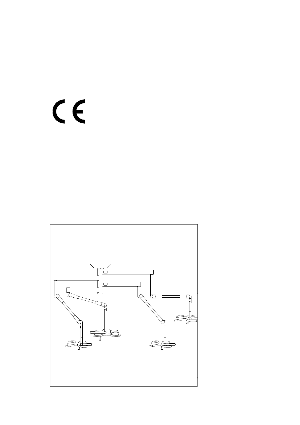
HANAULUX® 2000
Operating instructions
for all HANAULUX 2000 ceiling- and wall modells
56351039/C
Page 2

Operating Instructions 56351039/C HANAULUX
TABLE OF CONTENTS PAGE
®
2000
1.0 Important safety information
2.0 Description of the HANAULUX 2000 system
2.1 The HANAULUX concept 5
2.2 Standard components 5
2.3 Special components 6
2.4 Expandability 7
3.0 The HANAULUX benefits
3.1 Briliant cool light 8
3.2 In-depth illumination 9
3.3 Optimal hygiene 9
3.4 Easy manoeuvrability, true positioning 9
4.0 Operating your HANAULUX 2000 system
4.1 Mounting the sterilisable handle 10
4.2 Positioning the lights 11
4.3 Focussing the lights and changing the fieldsize 12
4.4 Dimming the light 13
4.5 Operating the HANAULUX 2007 iXL AF/2007 iXL
D
1
5
8
10
14
5.0 Important information about halogen bulbs
5.1 Changing the bulb 16
6.0 Adjustments
6.1 Adjusting the brakes 17
6.2 Adjusting the spring-arms 18
7.0 Cleaning/desinfecting and sterilising
7.1 Cleaning/ desinfecting the light 19
7.2 Cleaning the lenses 19
7.3 Sterilising the handles 19
7.4 Cleaning HANAUVISION 19
8.0 Maintenance and Repair
9.0 Troubleshooting your HANAULUX 2000 system
10.0 Technical Data
15
17
19
20
21
23
Page 3

1.0 Important safety information
Dear User!
• These instructions are intended for medical and technical staff in hospitals and
general practice.
• The work in the section entitled ”Maintenance” can be carried out by the operator’s
service man with due consideration for the safety notes.
• The unit can be cleaned by trained cleaning staff.
• Please read these instructions carefully before using the unit. This will allow you to
obtain the full benefit from the unit and will protect you and others from any injury.
Dear Operator!
These instructions apply to all HANAULUX 2000 ceiling and wall models.
• Your HANAULUX 2000 operating theatre lighting system was developed with
consideration for the high demands made on the surgeon’s eyes during surgery. Modern
technology and the HANAUCHROME optical system optimise the illumination and detail
recognition in the operating field.With the HANAULUX 2000 operating theatre lighting
system you have a unit which together with the HANAUCHROME optical system brings
brilliant light into the operating field. More light with greater colour reproduction and a
lower heat load penetrates deep into the wound.This unit has been designed using the
latest technology and is fail-safe. Nevertheless there are risks in using this unit,
especially when it is operated by staff who are not adequately trained or when it is used
incorrectly or not as intended.
• Using these instructions show cleaning staff how to clean and care for the unit.
• Where there are translations in foreign languages the German version of these
instructions is binding.
• Unauthorised modifications or alterations to the unit are not permitted for safety reasons.
• In the event of particular problems which are not covered in sufficient detail in these
instructions please contact your supplier for your own safety.
Keep these instructions in a safe place close to the unit so that they can be
consulted for safety notes and important information.
HANAULUX, HANAUPORT and HANAUVISION are registered trade marks of
MAQUET SA.
1
Page 4
Operating Instructions 56351039/C HANAULUX® 2000
The Operating Instructions are designed to be as clear as possible. The illustrations are all numbered
to correspond to the relevant text. This helps you follow the instructions in the text more easily.
These operating instructions refer to the following HANAULUX 2000 luminaire systems, as a single
light or in combination with other HANAULUX 2000 lights or accessories:
HANAULUX 2007 iXL/2007 iXL D/2007 iXL AF
HANAULUX 2005 i und 2005 iXL
HANAULUX 2004 i und 2004 iXL
HANAULUX 2003 i und 2003 iXL
HANAULUX 2002 i.
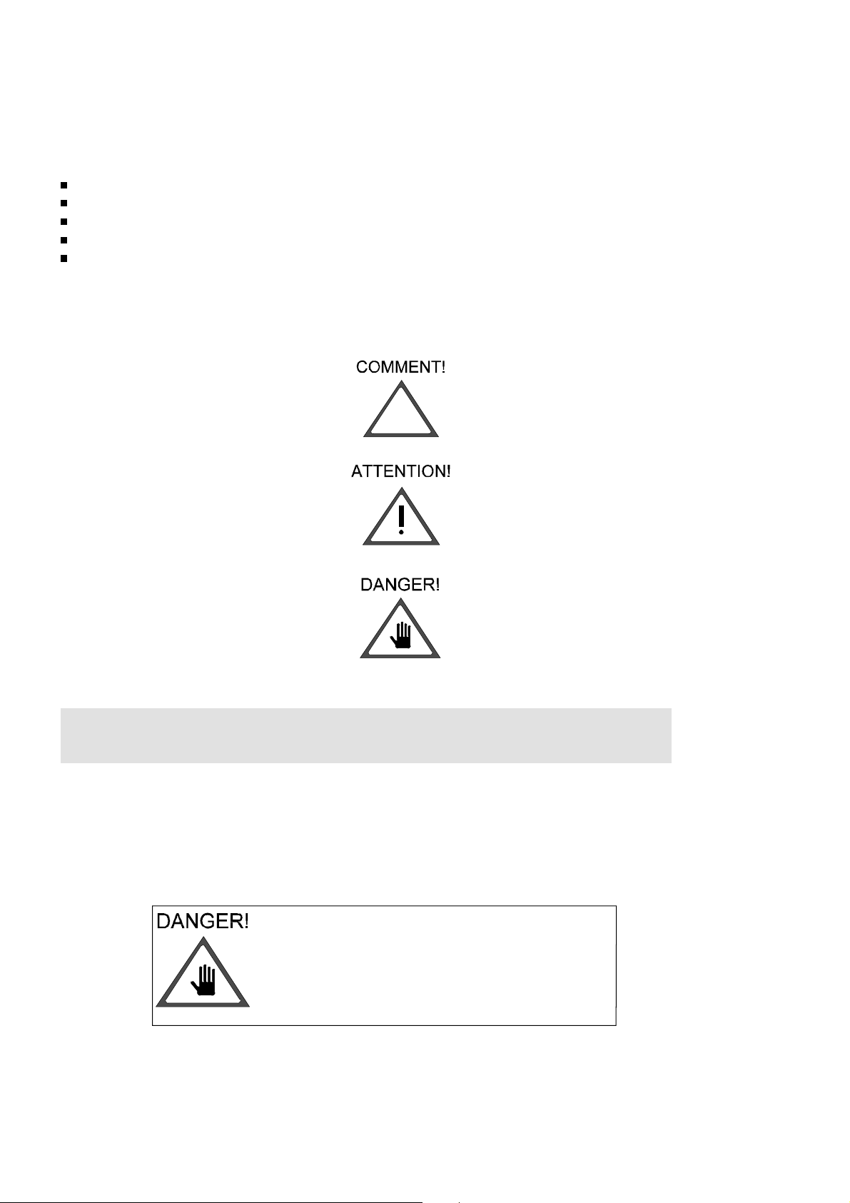
Explanation of the symbols used in these operating instructions:
1. COMMENT! is used where the correct functioning of the appliance could be affected.
2. ATTENTION! is used where the appliance could be damaged.
3. DANGER! is used where someone could be injured or killed.
1.1
General Safety Notes
To aid the surgeon where vision is difficult the light units offer a high degree of
illumination. The laws of physics mean that even visible light produces heat in the
operating field. If light fields from several light units are superimposed on each other,
illumination over 1000 W/m2 can be obtained. This involves an increased risk of the
tissue drying out and, especially in the case of longer use and reduced blood flow, there
is also the possibility of tissue damage.
A red band is located under the retaining ring on
the light unit side of the spring arm. This band
should not be visible during normal operation.If
the band is visible inform an authorised service
man immediately as there is a risk that the light
unit could fall.
2
Page 5

1.1.1 Use as intended
• The HANAULUX
®
2000 is for illuminating an
examination or operation area of a patient in
the clinic or doctor’s surgery.
• A single HANAULUX
®
2000 lamp is only
suitable for operations in which the light going
out does not endanger the patient.
®
• The HANAULUX
2000 light system must be
assembled as in the assembly instructions
accompanying the components.
• For service, repairs and alterations and as
accessories, only original Heraeus MED parts
may be used.
• A HANAULUX 2000 operation luminaire
system with several lamps is suitable without
limitation.
• The optimum working distance is 70 to 140
cm.
• The HANAULUX
®
2000 operation luminaire
system is suitable for continuous operation.
• Additional load on the light suspension is not
permitted.
• The light system is not for operation in areas
where there is danger of explosion
• The light system is not suitable for use in
combustible mixtures of anaesthetics with air
or oxygen or nitrous oxide.
• Keep the ambient temperature from 10°C to
40°C during operation.
• The relative humidity must not exceed 75%.
1.2.2 Requirements for safe operation
1.2.3 Transport and Storage
The following storage conditions apply for up to
15 weeks:
• Temperature- 25....+70°C
• Relative humidity 10%....75%
• Air pressure 500hPa....1060hPa
after which the values for the operating
conditions apply
• Do not subject the apparatus to severe
shaking
1.2.4 Disposal
Old units contain materials which are still
valuable. Do not take old units to the nearest
tip but find out about possible local
recycling from the town/ local authority.
The safe and correct function of the luminaire
system HANAULU 2000 within the given
technical data is only guaranteed if the following
conditions are fullfilled:
• The ceiling anchorage must be statically
safesecure and there must be a statics
certificate.
• The electrical installations of the rooms
concerned must conform to the nationally
valid specifications. VDE 0107 applies for
Germany.
• Extensions, alterations or repairs must be
carried out by Heraeus Med or an authorized
specialist.
HANAULUX halogen lamps can be disposed of
as domestic waste.
3
Page 6
Operating Instructions 56351039/C HANAULUX® 2000
2.1 The HANAULUX 2000 concept
The HANAULUX 2000 system is a modern
operating theatre lighting concept which fulfils the
highest requirements for light quality, hygiene
and flexibility. The basic principle of the
HANAULUX 2000 lighting systems is the
compatibility and interchangeability of the
individual components. The modular construction
concept allows configuration of the systems to
suit any surgical discipline.
The version "main light with SATELLIT" refers to
a combination with two or more different
lightheads.The lighthead with the highest
light-intensity is called the main light and is
always mounted on the lowest position, or
"position 1", of the central axle.
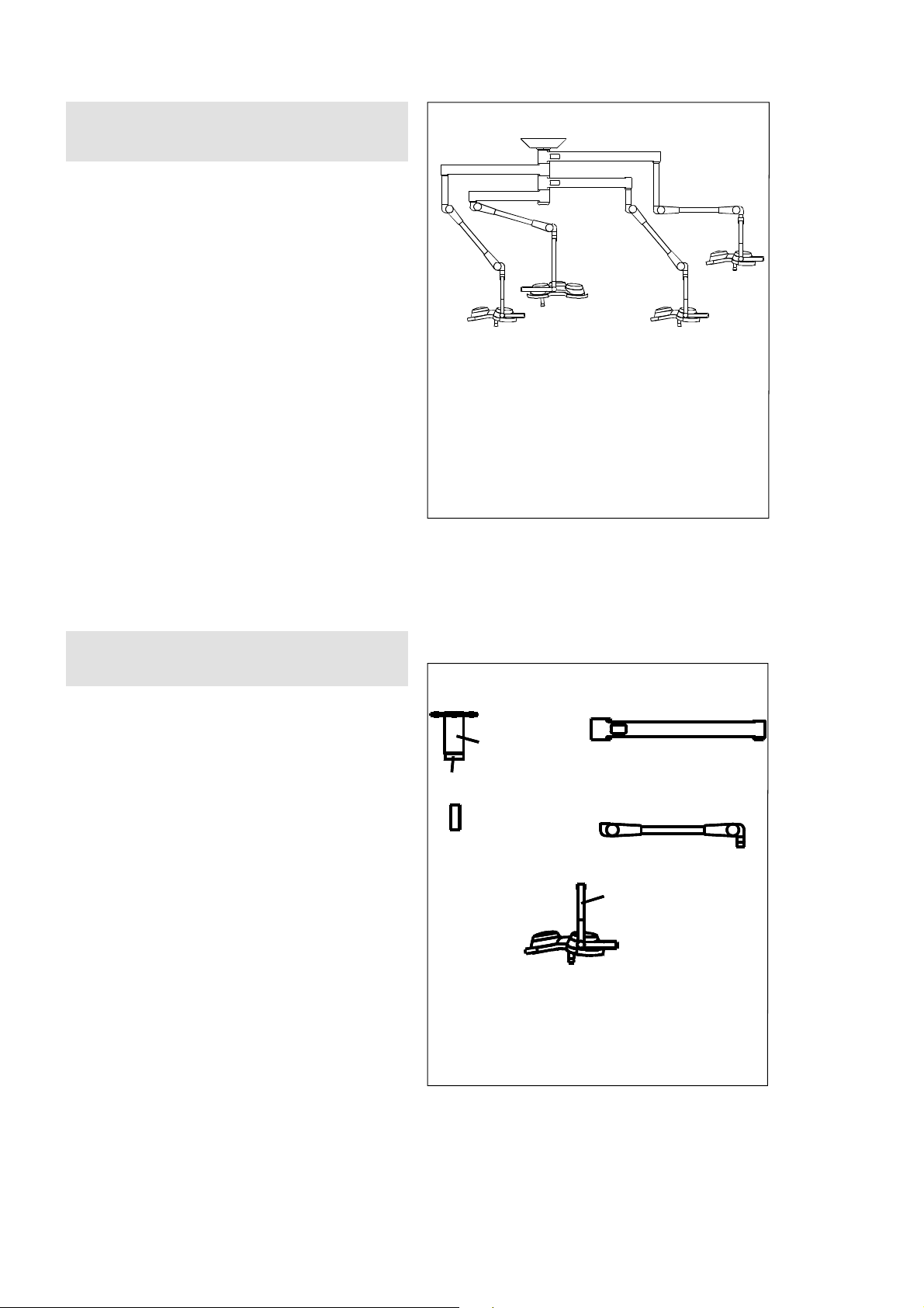
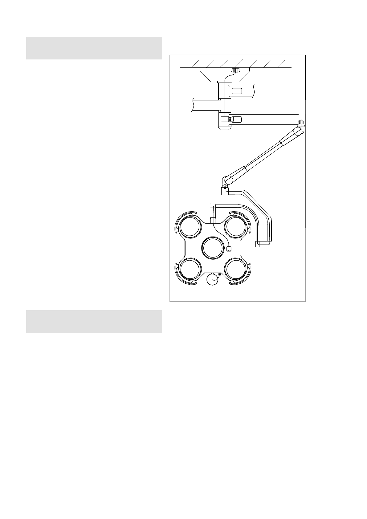
Fig. 2-1 shows a HANAULUX 2000 luminaire
system with the following components:
- 2005 main light, position 1
- 2003 SATELLIT light, position 2/3/4
2.2 Standard components
The standard HANAULUX 2000 components are
as follows:.
1 Flange tube
2. Central axle (in flange tube)
3. Extension-arm
4. Spacer
5. Spring-arm
1
2
4
6
3
5
6. Comfort arm
7. Lighthead with half semi-circular
bracket
7
4
Page 7
Operating Instructions 56351039/C HANAULUX® 2000
2.3 Special components
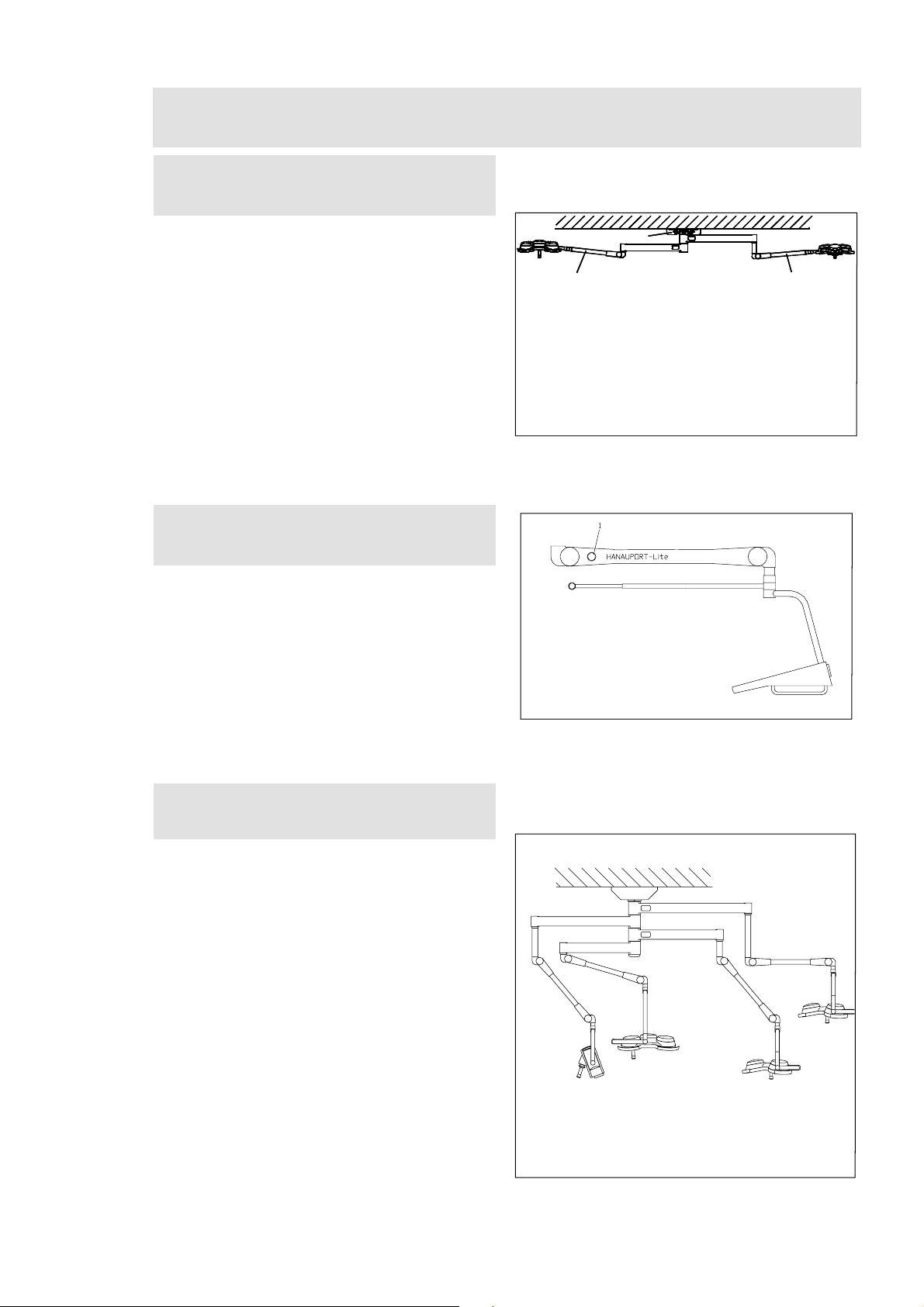
2.3.1. Special suspension system for low
ceilings
1
1
The full benefits of the HANAULUX 2000 system
can still be enjoyed even if the ceiling in your
operating theatre is very low. Two special
products are offered for low ceilings:
(i) A Flange-axle 1 which allows the central axle
to be mounted directly to the ceiling without
the need for a flange tube.
(ii) Straight spring-arms 2 with a restricted
upward movement offer optimal manoeuvrability
even in very low rooms.
2
Fig. 2.3.1
2
2.3.2. HANAUPORT-Lite equipment carrier
An appliance console which can support medical
appliances can be combined with HANAULUX
2000 light system. This console is suspended
from a HANAUPORT-Lite Arm and can bear
weights of 7-14 kg
2.3.4 HANAUVISION camera system
The HANAUVISION camera system combines all
the advantages of the latest in camera
technology with the ease of manouevrability of
the HANAULUX 2000 suspension system.
Fig. 2.3.2
A separate Installation and Operating Instruction
is available for the HANAUVISION system.
Fig. 2.3.3
5
Page 8
Operating Instructions 56351039/C HANAULUX® 2000
2.3.5 Versions with limited rotation
The versions with camera (without WDV
models), have additional cables inside the arms
and central axle. The rotation in these joints is
however limited in order to protect the additional
cables. The rotation in the central axle is limited
o
to 330
exact details please see the data sheet for the
product.
It is always possible to limit the rotation in the
axle or the arms in a HANAULUX 2000 system
should this be required. Please contact your
Heraeus Med service agent for further
information.
, the arms are limited to 360o or 225o. For
2.4 Expandability
The HANAULUX 2000 luminaire system can also
be prepared for the later installation of a
SATELLIT light, or a HANAUVISION camera
system. In this case, one axle position is left
"free" and is covered with a sleeve until the
SATELLIT light or camera is to be installed.
Fig. 2.3.4
6
Page 9

Operating Instructions 56351039/C HANAULUX® 2000
3.0 The HANAULUX Benefits
3.1 Brilliant cool light
The heart of the HANAULUX 2000 lighting
system is the HANAUCHROME optical system.
Each HANAULUX 2000 lightheads has a different
number of HANAUCHROME optical systems,
from one in the HANAULUX 2001 up to five units
in the HANAULUX 2005.
Each individual HANAUCHROME system
consists of a number of specially designed
components, all optimised to ensure maximum
illumination of the operating field.
A special halogen bulb 3, with a unique filament
geometry generates the high light-intensity.
A revolutionary glass reflector 2, coated with a
colour correcting conversion film, and an infrared
reflection disc 4 remove the heat from the light,
producing the famous HANAULUX cool light.
A specially developed double Fresnel lens 1,
creates a homogenous lightfield and completes
the HANAUCHROME optical system which
guarantees a cool "white" light for every surgical
discipline.
The HANAUCHROME socket 5, completes the
system. This socket is constructed to be extra
safe and ensure that changing an
HANAUCHROME bulb is never dangerous.
reflection disc 4 remove the heat from the light,
producing the famous HANAULUX cool light.
Abb. 3.1
7
Page 10

Operating Instructions 56351039/C HANAULUX® 2000
3.2 In-Depth illumination
The double Fresnel lens produces a cascade of
focal points underneath the HANAUCHROME
system. The result is a well illuminated field with
homogeneous light distribution and great
operating depth (50 cm), almost cylindrical in
shape.
3.3 Optimal hygiene
Every light unit in the HANAULUX 2000
luminaire system has a sealed housing with
smooth surfaces. Chrome plated outer handles 1
and a removable,sterilisable central handle 2 are
mounted on this housing for moving the light. All
handles are robust and chemically resistant and
are designed to withstand aggressive disinfecting
agents.
The high glance powder coat paint system has a
low surface energy. This means that it does not
easily attract dirt or germs and is easy to clean.
This tough paint system is also particularly
resistant to scratches and scuffs.
3.4 Easy manoeuvrability, true positioning
Even if the HANAULUX 2000 system is equipped
with several SATELLIT lights and a
HANAUPORT Lite arm, all can be easily moved
without damage or interference. Three special
features make this possible: graduated extension
arm lengths, graduated spacers and
limitless rotation of the main joints.
The weight of the lightheads is exactly
compensated by spring balances in the
spring-arms which also hold every position. The
finely adjustable brakes in the joints of the
supporting arms ensure light, easy movement
and true positioning.
Abb. 3.2
Abb. 3.3
1
1
2
3
4
1. 1200 mm extension-arm with spacer 4
2. 1050 mm extension-arm with spacer 3
3. 900 mm extension-arm with spacer 2
4. 750 mm extension-arm
5. 900 mm extension-arm for 2006 iXL TV /
2007iXL lights
Abb. 3.4
5
8
Page 11

Operating Instructions 56351039/C HANAULUX® 2000
4.0 Operating your HANAULUX 2000 luminaire system
4.1 Mounting and removing the
sterilisable handle
All HANAULUX 2000 models have a sterilisable
handle which can be removed and sterilised.
To mount the handle 1, push it up onto the
handle pillar until the ball bearing 2 snaps into
place, as shown. The ball bearing must make an
audible click.
Handles which are cracked or
damaged must be replaced
immediately. Otherwise they could
fall down into the operating area
during an operation.
Fig. 4.1
To remove the handle, push in the ball bearing 2
and gently pull handle off pillar.
4.2
The weight of the appliance is balanced by
weights in the shelf. These are installed during
assembly of the appliance pendant. When
changing the appliance for another one which
weighs more or less than the previous appliance,
the weights in the shelf must be changed. For
further details please refer to the assembly
instructions. The spring arm can be locked in the
uppermost, lowermost and mid position by
pressing the lock button 1, if the appliance has to
be removed from the pendant. Press button 1
and move the arm in the desired direction until it
clicks fully into position
HANAUPORT Lite with Equipment
Carrier
Fig. 4.2
Fig. 4.3
9
Page 12

Operating Instructions 56351039/C HANAULUX® 2000
4.2.2. Positioning the lights
The extension arm at position 1 is specially
shaped to allow the light to be positioned directly
under the central axle, as is required for some
disciplines.
In order to achieve best possible mobility please
position this arm in relation to the second light in
a M position, as shown in fig. 4.2-2. In the M
position the spring-arm is always on the inside of
the extension arm, never on the outside, so that
the light can be easily moved.
Failure to position the arms in the
M position shown could result in
the spring-arms hitting the
extension-arms and damage
could occur.
To move the lighthead up or down:
Make sure that the sterilisable handle 2 is in
position (For details on mounting the handle
please see chapter 4.1).
Grip the handle tightly with your hand and gently
push or pull the lighthead upwards or downwards
into position.
To move the lighthead from side to side
Firmly grip the outer handles 1 with both hands
and gently pull or push the lighthead towards you
or away from you.
The lighthead must never be turned
upside down while switched on, as
the heat generated in the optical
system will not be able to radiate
downwards and the optical system
could be damaged as a result.
:
Fig. 4.2.2
10
Fig. 4.2.3
Page 13

Operating Instructions 56351039/C HANAULUX® 2000
4.3 Focussing the lights
4.3.1 Avoiding light spill
When focusing or adjusting the fieldsize of your
lights please keep the fieldsize to the minimum.
The fieldsize should be just sufficiently large to
illuminate the incision and surrounding tissues.
If the field is too big, light spill around
the operating area could dazzle and
tire the eyes.
4.3.2 Focussing the light
To focus the 2002-2005 models with
ERGO-FOCUS, proceed as follows::
1. Make sure the sterilisable handle is correctly
mounted.
2. Make sure the light is positioned within 70 to
140 cm of the operating field.
3.Turn the handle 1 until it locks into place. The
field remains in this position focused on the
operating area.
4.To focus the
handle until the field is round and is of the
required field size.
This also applies to the special model 2007
Autofokus. Please consult Section 4.5 for
information on how to set the field size of this
light at the controls.
2007
model turn the central
Fig. 4.3.1
To change the fieldsize turn the sterilisable
handle 1:
to the right to increase
to the left to decrease the fieldsize.
or
Fig. 4.3.2
11
Page 14

Operating Instructions 56351039/C HANAULUX® 2000
4.3.3 Working area and focus range
Your HANAULUX 2000 lights have a special
optical system (see chapter 3.1) which has the
unique feature of providing a column of light
which approximately 50 cm long. In practise this
means that once the light is focussed the lighting
conditions within an area of 50 cm are more or
less uniform. Within this area minimal
refocussing is required.
The focus range or operating distance of the
lights is 700-1400 mm. This distance is
measured from the bottom of the light unit.
If the light is closer than 70 cm to
or further than 140 cm from the
operating field the light cannot be
properly focussed.
Fig. 4.3.3
4.4 Dimming the light
We recommend the installation of a dimmer for
varying the light-intensity. The Heraeus
recommended dimmer allows the light-intensity
to be varied between 50% and 100% and is
mounted in a control panel on the wall. For
further details of the recommended dimmer
please see our "Preparatory Measures for
Installing HANAULUX 2000."
Before starting any operation please adjust the
illuminance in accordance with the requirements
of the intended operation and the surgeon’s
personal preference.
If the operation is to last more than 2 hours our
tip is to begin the operation with a lower
light-intensity, e.g. 50 %. This allows you to
increase the light-intensity gradually during the
operation and to thus compensate the eye
fatigue which often occurs during longer
operations.
12
9
6
50%
Fig. 4.4
3
h
lux
9
100%
12
3
6
12
Page 15

Operating Instructions 56351039/C HANAULUX® 2000
4.5 Operating the 2007 iXl D and 2007 iXL AF
4.5.1 Operating the 2007 iXL AF light
The HANAULUX 2007 iXL AF is equipped with
an autofocus system which automatically
regulates the fieldsize. In order to optimise the
use of your 2007iXL AF light the following must
be observed.
The autofocus system has a working range
of 70 to 140 cm, measured from the bottom edge of the lighthead to the operating
area.
The light tests itself when it is turned on.
This test lasts about 30 seconds. In order
to activate the light after this test a handle
must be lightly touched.
The autofocus system is now ready for operation.
The fieldsize can be adjusted at the touchpanel
and the middle handle. To change the fieldsize at
the touchpanel, the switches "+" or " -" must be
pressed. To increase the fieldsize press the
switch 1, to decrease it press the switch 2. The
corresponding light diode lights up.
The autofocus system is now set. The fieldsize
will remain the same during the entire operation.
The autofocus only reacts when the distance
between the light and the operating field
increases. The system will not react if hands or
tools are in the operating field. If the light is to be
refocussed to a higher point before or after the
operation a handle must be lightly touched. The
autofocus system will now focus on the first
object it finds within its working range.
The autofocus system can be turned off by
pressing switch 3. Press switch 4 to turn the
system on again.
4.5.2 Operating the dimmer on the
2007 iXL AF and 2007 iXL D
The 2007 iXL AF and 2007 iXL D lights are
equipped with a light-intensity regulator on the
touch panel. For important information about the
proper use of a dimmer please see chapter 4.4
Press switch 5 to reduce the light-intensity,
switch 6 to increase.
1
2
4
3
Fig. 4.5
6
5
13
Page 16

Operating Instructions 56351039/C HANAULUX® 2000
5.0 Important information about halogen bulbs
5.1 Changing a bulb
The shape and structure of the filament of the
halogen bulbs used for the HANAULUX 2000
DUO lighting systems are specially designed for
the HANAUCHROME optical system (see
chapter 3.1).
Only original Hereaus bulbs should be used as
any of the following could otherwise occur:
A lower light-intensity
A higher temperature increase in the operating
field
Colour falsifications
Inhomogenous lightfield
Reduced bulb life
Damage to the optical system.
The halogen bulbs significantly
determine the technical data for the
HANAULUX operating theatre lights.
They are, therefore, accessories
under the terms of the law on
medical products (§ 3 MPG) and
must therefore only be brought into
circulation with the CE symbol as
this type of accessory.
Important information about voltage,
light-intensity and life of bulb and
optical system
The HANAUCHROME bulbs and optical system
are rated for a voltage of 22,8 V (AC or DC) at
the bulb socket. Higher voltages should be
avoided as they cause a decreased bulb life. In
extreme cases the life of the optical system could
be also be reduced.
Fig. 5.0
In order to optimise the life and
performance of the optical system
the voltage to the bulb should not
exceed more than 10 % above
the rated value of 22,8 V.
Excessive voltages could result in
damage to the optical system.
Voltage
at flange
(V)
Voltage
at bulb
(V)
Rel. light
intensity
(%)
23.0 21.8 90 120
23.5 22.3 96 105
24.0 22.8 100 100
24.5 23.3 105 95
25.0 23.8 109 85
25.5 24.3 70 50
Rel. life
of bulb
(%)
A lower voltage results in a lower light-intensity.
Significantly lower voltages can also reduce the
life of the halogen bulb.
Table showing the relationship between voltage,
light-intensity and the life of the bulb.
14
Page 17

Operating Instructions 56351039/C HANAULUX® 2000
The bulb generates considerable
heat which is emitted through the
top of the lighthead. The covers
will therefore be quite warm to the
touch.
Never change a bulb as long as
the cover is still warm as you could
burn yourself.
Switch off the light system.
1. With one hand push the button 2 in as far as
possible. At the same time turn the cover 1
towards the right or the left until it opens.
2. Remove the cover 1 and place carefully to one
side. The cover will not fall out as it is attached
to the lighthead by a grounding cable.
3. Open the two clips 3 on the socket 4.
4. Gently pull the socket 4 as far as possible out
of the socket holder.
5. Remove bulb 5 from socket 4.
Never touch a bulb with bare
hands as the life of the bulb could
be considerably shortened.
7. Still holding the bulb 5 in the plastic
packaging, gently push the bulb as deeply as
possible into the socket 4. Make sure the bulb is
sitting straight. Gently remove the plastic
packaging from the bulb.
6. Carefully unpack the new bulb by tearing the
bottom of the plastic bubble packaging and
pushing the bulb down until the pins protrude
about 1.5 cm out of the packaging.
Fig. 5.1.a
Fig. 5.1.b
8. Replace the socket 4 in the socket holder,
taking care not to knock the bulb in the
process.The holes on the socket 4 must be
matched up to the corresponding fittings on
the socket holder. Close the two spring clips 3.
9. Closing the lighthead cover: Place the cover 1
on the light, making sure that the spring latch 2
is lined up to one of the arrows. Gently press
down on the cover 1 and at the same time
slowly turn the cover in the direction indicated
by the arrow until the cover snaps audibly into
place.
15
Page 18

Operating Instructions 56351039/C HANAULUX® 2000
6.0 Adjustments
The brakes are always adjusted during the
commissioning phase and before official
handover. The brakes should always be
adjusted so that the manoeuvrability of the light
is as light as possible but the light still maintain
it’s position.
As with all mechanical parts it is to be expected
the brakes and the spring balance will fatigue or
wear and need readjusting.
6.1 Adjusting the brakes
Tools:
A flatheaded screwdriver, ca. 6mm is required.
The brake adjustment points are shown in fig.
6.1.
Should the brakes be worn they will be too soft
and the light could drift from side to side.
Should the brakes be too hard the light will be
difficult to move. In either case the brakes can be
easily readjusted.
Single Lights: Single lights, ceiling and wall
version, do not have a brake screw at position 1.
The 2003 i and 2004 i/iXL single lights have
brake screws at Points 2, 3 and 4, the 2002 i
single light only has them at Points 3 and 4.
All brake screws are slotted screws.
To set the brake force, gently tighten or loosen
the brake screw.
All other screws are fixing screws
and should not be adjusted as a
part could loosen and fall down.
Fig. 6.1
16
Page 19

Operating Instructions 56351039/C HANAULUX® 2000
6.2 Adjusting the spring-arms
Should the lighthead drift downwards or jump
upwards then the spring balance in the
spring-arm is fatigued and must be readjusted.
The adjustment method varies with the
spring-arm version.
6.2 .1 Adjusting the spring-arms 2002 i
-2005 i/iXL
1. Open the spring-arm covers 1 by removing
the screw 2.
2. Use a small screwdriver to gently force the
covers apart.
3. Push the spring-arm upwards until the adjustment nut is visible in the opening 1 of the
spring-arm. (Fig. 6.2.b)
4. Insert the metal pin which is supplied with the
arm into the nut and turn nut to adjust spring
force.
5. Place the spring-arm covers on the pring-arm.
The holes for the screw 3 and the hole in the
cover nose must line up. Make sure that the
metal strips 2 are not bent or twisted.
6. Tighten screw 3 to fix covers into place. Check
that covers are sitting properly.
The covers must always be screwed
into place. Otherwise they could open
and fall off during operation.
Fig. 6.2.c
Fig. 6.2.a
Adjust the spring force, so that:
(i) The strength required to pull the spring-arm
up or down is the same in both directions,
(ii) The lightheads remain stable and firm in
both directions.
Turning the nut decrease the spring force
Turning the nut increases the spring force
6.2.2
Remove the fixing screw 1 and the cover 2. Push
the spring-arm upwards until the adjustment nut
is visible in the opening 3 of the spring-arm.
Adjust spring-arm as described in steps 3 and 4.
Fig. 6.2.d
Straight spring-arm:
Fig. 6.2.b
17
Page 20

Raise the arm above the horizontal to facilitate ad-
justment (Fig. 2).
6.3 Adjustment of Acrobat
2000 spring arm
Unscrew to
raise stop
Screw to lower
stop (to horizontal)
Abb. / Fig. 1
Abb. / Fig. 2
6.3.2 Adjustment of spring arm:
balancing
Unscrew to
increase the
strength of the
spring arm (cupola goes up)
Screw to
reduce the
strength of
the spring arm
(cupola goes
down)
Use the 5 mm Allen key provided
(Fig. 1).
Reinstall the arm to check the new position
obtained. Adjust if required.
Make sure that the cupola appears
to weigh the same during raising and
lowering and that it remains stable in any
position in which it is left.
+
-
Abb. / Fig. 3
6.4.1 Adjustment of spring arm:
upper stop
6.4 Adjustment of Acrobat
2000 straight spring arm
Locate the setting. Use the rod provided (Fig. 3)
Turn downwards to
lower stop (to
horizontal)
Turn upwards
to raise stop
Reinstall the side covers, engaging the end first
(Fig. 4).
Then engage the other end taking care to leave
the spring blades on the outside.
Fasten the covers using a 2.5 mm Allen key
(Fig. 5).
Lower the arm to reinstall the top spring blade.
Then raise the arm to reinstall the bottom blade.
Abb. / Fig. 4
Abb. / Fig. 5
6.3.1 Adjustment of spring arm:
upper stop
Operating Instructions 56351039/C HANAULUX® 2000
6.4.2 Adjustment of spring arm:
balancing
See 6.3.2 Adjustment of spring arm: balancing
18
COMMENT!
COMMENT!
Page 21

Operating Instructions 56351039/C HANAULUX® 2000
7.0 Cleaning/desinfecting and sterilising
7.1 Cleaning/ desinfecting the
light
Sterilising or cleaning agents which
The HANAULUX 2000 system has a special
powder coat paint coating which is easy to clean
and resistant to chemicals. The outer handles are
chrome plated to make them chemically
resistant.
Note
The user has to pay attention to th
demands of the national committee for
hygiene and disinfection.
e
7.3 Sterilising the handles
contain alcohol should never be
used on the HANAULUX 2000
lenses.
Alcohol attacts the lenses causing
them to become cloudy or milky
and the light-intensity will therefore
decrease.
To avoid damage to plastic and glass
parts, do not use any scouring agent, or
any cleaning agent which is alkaline
acidic or contains alcohol (e.
propanal, ...) or aldehyde.
• Only disinfect the apparatus when it i
cold.
•We recommend our teste
cleaning/desinfection agent HANAU
-clean.
•Because there are a
cleaning/desinfecting agents on the
market, and we do not know their
interactions with plastic used, damage
cannot be ruled out if other agents are
used.
•For cleaning, use a soft, lint-free cloth.
7.2 Cleaning the lenses
g. ethanol
great number of
The central handles, both metal and plastic, can
withstand up to 350 sterilisation cycles without
damage, provided they are correctly sterilised.
The handles should be sterilised as follows:
The handle should be placed upright in the
sterilisation unit with the opening facing
s
downwards to prevent any condensation occuring
in the cavity. Otherwise the handles could crack.
d
The sterilisation temperature should not exceed
o
134
C. The handles should not come into contact
with any other appliances during the sterilisation
process.
Handles which show signs of wear
(discolouration, cracking, etc.)
should be replaced immediately. A
damaged handle could fall off into
the sterile area during an
operation.
7.4 Cleaning HANAUVISION
The HANAULUX 2000 lenses are made of tough,
high quality acrylic. As all plastics are subject to
aging processes the lenses should be visually
inspected from time to time. Alcohol based
cleaning agents should not be used. We
recommend the cleaning agent HANAUCLEAN.
Lenses which are damaged,
cracked or cloudy shoudl be
immediately replaced as they
could otherwise break during an
operation.
For details regarding the special care and cleanig
of your HANAUVISION camera system please
refer to the separate HANAUVISION operating
Instructions.
19
Page 22

Operating Instructions 56351039/C HANAULUX® 2000
8.0 Maintenance and repair
HANAULUX operating theatre lights have been
designed and built to last for a very long time.
However, to guarantee perfect and safe
operation over long periods, it is necessary to
check the lights regularly. Regional regulations
must also be observed when doing this.
8.1 Inspection by the operator
All HANAULUX 2000 products are to be
inspected by the operator every six months with
attention to the following points:
- defects in paint work
- cracks in plastic parts
- deformation in the supporting system
In the case of any problems or damage,
please inform our customer services.
8.2
Inspection by the Service
When ordering spare parts please observe the
following:
Identifying the correct parts:
Please check the model type on the type label
which is to be found on lighthead axle.
Model Reflector
(Part. no.)
2006/7 iXL
2007 iXL AF
2004/2005 iXL
2002 i to 2005 i
Visible markings:
In order to facilitate identification of the correct
parts the reflectors and lenses are marked as
follows:
56052959
56052969
56052961 56052962
56052961 56052609
Lenses
(Part. no.)
56050730
56050732
All HANAULUX 2000 products are
serviced once a year by
HERAEUS Med or an authorised
customer services office. This
service covers the following
points:
- performance check test
- electrical safety test
- inspection of the supporting system
The service man is trained in how to conduct
the tests.
8.3 Important information about
Description Part. No.
HANAUCHROME bulb
HANAUCHROME bulbs, 8 off 56 051 757
Sterilisable handle, plastic 3 off 560 50 756
Sterilisable handle, metal 3 off 56 050 755
HANAUCLEAN 56 051778
The HANAULUX 2000 offers two different light
systems:
- HANAULUX Improved (i)
- HANAULUX Improved Extra Large (iXL)
, 1off
56 115 282
Fig.1: Reflectors
Marking: Label with part number
Fig. 2: Lenses
2 strips for 2002-5 i, 3 strips for 2004/5 iXL
Reflectors and lenses may only be
used in the combinations shwon
above. Other combinations could
result in poor light quality.
20
Page 23

Operating Instructions 56351039/C HANAULUX® 2000
9.0 Troubleshooting your HANAULUX 2000 system
Fault Possible cause Corrective measure Reference
Suspension System/Manoeuvrability
Light is heavy,
difficult to move
Light is too light,
drifts easily
Lighthead drifts
downwards
Lighthead jumps
upwards
Spring-arm
knocks against
ceiling
Spring arm
covers fall off
Metal strips
under spring-arm
covers broken
Extension-arms
move together,
scrape against
one another
Brakes are too tight Readjust brakes Chapter 6.1
Brakes are too loose
or worn
Spring-balance in
spring-arm is tired,
worn
Spring-balance is too
tight
Spring-arm upper
movement must be
restricted
Covers have been
knocked/damaged
- Arm has been
knocked/damaged
- Covers have been
incorrectly mounted
Arm has been
knocked too hard and
tilted
Readjust brakes or replace Chapter 6.1
Readjust spring-balance Chapter 6.2
Readjust spring-balance Chapter 6.2
Height restrictor must be adjusted.IContact service
agent
Replace covers. Check that arms
are correctly used
Replace arm
Check covers are correctly
mounted
Light must be checked
immediately
Chapter 4.2.2
Contact service
agent
Chapter 6.2
Contact service
agent
Optical system/Lighting parameters
Light flickers/
power fails when
light is moved
Light-intensity is
too low
Light not white/
colour wrong
Light too bright
Lightfield not
round
Life of bulb too
short
Bulbs explode
Electrical contact is
damaged
- Voltage is too low
- Wrong bulb(s) in
light
- Lenses damaged
from wrong cleaning
agent
- Wrong lens!
- Wrong bulb(s)
- Wrong lens
- Wrong bulb(s)
- Voltage too high
- Wrong bulbs
- optical system
damaged
- Wrong bulb(s)
- Voltage too high
- Voltage too high
- Short circuit in wiring
Contact must be replaced Contact service
agent
- Electrician must check
- Check bulb, replace
- Lenses must be replaced,
cleaning must be changed
- Check lens version
Replace bulb
Check lens version
- Check bulb, replace
- Electrician must check
- Check bulb, replace
- Optical system must be replaced
- Check bulb, replace
- Electrician must check
Electrician must check
- Chapter 11
- Chapter 5.0
- Chapter 8.0
- Chapter 9.0
- Chapter 5.0
- Chapter 9.0
- Chapter 5.0
- Chapter 11.0
Chapter 11.0
Chapter 5.0
21
Page 24

Operating Instructions 56351039/C HANAULUX® 2000
Fault Possible Cause Corrective Measure Reference
Lenses
Lenses cracked,
splitting
Lenses have
melted, bubbled
on inside
Wong cleaning agent
used
- Voltage too high
- Wrong bulbs used
- Replace lenses
- Check cleaning agent
- Replace lenses
- Check voltage
- check bulbs
Chapter 8.0
Chapter 5.0
Sterilisable Handles
Sterilisable
Handles do not
last long enough
(less than 150
cycles)
Handles are
cracked or
discoloured
Handles fall off
Handles incorrectly
sterilised
Handles have reached
end of working life
Handles are
damaged/worn
Check sterilisation process Chapter 8.0
Replace immediately Chapter 8.0
Replace immediately Chapter 8.0
Focussing/Field change
Light does not
focus when
middle handle
turned
Focus is
stiff/jerky
Light cannot be
focussed
properly,
although focus
mechanism
works
Focus mechanism
broken
Focus mechanism dry,
must be greased
Light is too close to /
too far from operating
field
Replace immediately Contact service
agent
Grease mechanism Contact service
agent
Check that light is within working
area
Chapter 4.3
If any of these faults reoccur or cannot be rectified, please contact your service
agent.
22
Page 25

Operating Instructions 56351039/C HANAULUX® 2000
10.0 Technical data: Lighting parameters
The lighting parameters are measured in accordance with EN 60601-2-41.
Model Light-intensity
(kLux)
2007 iXL
2007 iXLAF
2006 iXL TV
2005 i
2005 î TV
2005 i NRH
2005 iXL
2005 iXL TV 100 20-30 55 70-140
2005 iXL NRH
2004 i
2004 iXL
2004 i TV
2003 i
2002 i
130 20-35 60 70-140
130 20-35 60 70-140
115 20-35 60 70-140
130 17-25 55 70-140
130 17-25 55 70-140
130 17-25 55 70-140
100 20-30 55 70-140
100 20-30 55 70-140
100 17-25 50 70-140
80 20-26 50 70-140
100 17-25 50 70-140
80 17-23 50 70-140
60 17-23 40 70-140
Lightfield
(cm)
Working area
(cm)
Focussable
area (cm)
23
Page 26

10.1 Technical data: Mechanical data
Model max.
diameter of
rotation
(cm)
Vertical
action
(cm)
Mass of
lighthead
*
(kg)
Mass of
suspension
system
(main light)
(kg)
Mass of
Sat.
suspension
system
(kg)
2007 iXL
360 100 29 62 -----
2007 iXL AF 360 100 34 62 -----
2005 i 420 115 17 55 28
2005 i TV
420 115 20 55 28
2005 i NRH
420 115 15 55 28
2005 iXL
420 115 17 55 28
2005 iXL TV
420 115 20 55 28
2005 iXLNRH
420 115 15 55 28
2004 i
420 115 16,5 52 18
2004 iXL
420 115 16,5 52 18
2004 i TV
420 115 19 55 28
2003 i
420 115 13,5 52 18
2002 i
420 115 8,5 52 18
* All basis version except 2004/5 i/iXL TV which is always comfort version.
Mass of ceiling anchor ring with shortest flange tube: ca. 20 kg.
For longer flange tubes an extra 1,1 kg must be added for every 10 cm length.
Operating Instructions 56351039/B HANAULUX® 2000
MAQUET S.A.
Parc de la Limère
Avenue de la Pomme de Pin
ARDON 45074 ORLÉANS CEDEX 2
Tel: +33 (0) 2 38 25 88 88 Fax: +33 (0) 2 38 25 88 00
www.maquet-sa.fr
 Loading...