

Page 1
x
User's Manual
FLOW-i 4.2
Anesthesia System
Page 2

Page 3

Table of contents
| Table of contents |
1
2
3
4
5
6
7
8
9
10
11
12
13
14
15
16
17
18
5|Introduction
9|Important
17|System overview
47|Startup and system checkout
65|System functionality
119|Breathing system
149|AFGO (Additional Fresh Gas Outlet, Option)
155|Membrane buttons
183|Alarms and patient safety
209|Ventilation modes
233|System shutdown
235|Routine cleaning and maintenance
265|Technical specifications
291|EMC Declaration
299|Definitions
301|Certificates
303|Index
309|Log sheet
FLOW-i 4.2, User's Manual
Infologic 1.67
3
Page 4

| Table of contents |
4
FLOW-i 4.2, User's Manual
Infologic 1.67
Page 5

1 Introduction Table of contents
| Introduction |
6|Indications for use1.1
6|Intended use1.2
7|Using this manual1.3
1 |
FLOW-i 4.2, User's Manual
5
Page 6
| Introduction |
| 1
1.1 Indications for use
The indication for FLOW-i Anesthesia System is administering inhalation anesthesia while
controlling the entire ventilation of patients with no ability to breathe, as well as in supporting
patients with a limited ability to breathe. The system is intended for use on neonatal to adult
patient populations. The system is intended for use in hospital environments, except MRI
environment, by healthcare professionals trained in inhalation anesthesia administration.
1.2 Intended use
The system is intended for use in administrating anesthesia while controlling the entire ventilation
of patients with no ability to breathe, as well as in supporting patients with a limited ability to
breathe.
The system is intended for use by healthcare professionals, trained in the administration of
anesthesia.
The system is intended for use on neonate to adult patient populations.
The system is intended for use in hospital environments, except the MRI environment.
When not in operation, the system is designed for in-hospital transport.
6
FLOW-i 4.2, User's Manual
Page 7

| Introduction |
1 |
1.3 Using this manual
This manual is divided into the following
chapters:
• Chapters 1 and 2: Important information
before use, along with a basic introduction
to the system and User's Manual.
• Chapter 3: Overview of the functional parts
of the system.
• Chapters 4 through 11: Understanding and
working with the system.
• Chapter 12: Routine cleaning and
maintenance procedures.
• Chapter 13: The technical specification of
the system.
• Chapter 14: EMC Declaration
• Chapter 15: Terminology and definitions
• Chapter 16: Certificates
• Chapter 17: Index
Important information is highlighted with
Warning or Caution, where:
WARNING! Indicates critical information
about a potential serious outcome to the
patient or the user.
CAUTION: Indicates instructions that must
be followed in order to ensure the proper
operation of the equipment.
• Chapter 18: Log sheets
References made to optional accessories
within the FLOW-i User's Manual are
accompanied by the text 'option' in brackets.
FLOW-i 4.2, User's Manual
7
Page 8

| Introduction |
| 1
8
FLOW-i 4.2, User's Manual
Page 9

2 Important Table of contents
| Important |
10|General information2.1
11|Connection2.2
12|Operation2.3
13|Installation and service2.4
14|Accessories and auxiliary equipment2.5
2 |
FLOW-i 4.2, User's Manual
9
Page 10

| Important |
| 2
2.1 General information
• The following applies throughout this User's
Manual:
- 'FLOW-i', 'anesthesia system' and
'system' represent FLOW-i anesthesia
system version 4.2.
• This manual applies to the FLOW-i
anesthesia system models C20, C30 and
C40, and optional equipment that can be
fitted onto these.
• Only authorized personnel who are well
trained in its use should operate the
anesthesia system. It must be operated
according to the instructions in this User's
Manual.
• Gas volumes, flows and leakages
associated with the breathing system are
stated in the technical specifications and
adhere to BTPS reference conditions. (Body
temperature, ambient pressure, Saturated).
• All gas concentration readings are normally
referenced to dry gas conditions, ambient
room temperature and atmospheric
pressure (ATPD).
• The condition for measured inlet gas
pressures and flows is STPD (Standard
Temperature and Pressure Dry); 20° C,
standard pressure at 101.3 kPa and 0 %
relative humidity (dry).
• All data on pressures are given in either
cmH2O or bar, where
1 cmH2O = 1 hPa = 1 mbar
1 bar = 15 psi = 1 atm = 1 kgf/cm2 (kp/cm2)
• The anesthesia system is not made with
natural latex.
• Applied parts, i.e. equipment making
physical contact with the patient, comprise
gases (including agents) and the patient
mask.
• If the mains power supply is interrupted,
the internal battery will provide temporary
power to the system (approx. 90 minutes
when fully charged).
• The fresh gas/gas supply outlets are not
affected by switch to battery power.
• Malfunction of the central gas supply can
potentially cause one or several of the
devices connected to the system to stop
their operation simultaneously.
• When the system is in use, a backup gas
supply shall always be available.
• If the central gas supply is interrupted, the
backup gas cylinders O2/N2O or O2/Air
(option) will provide gas to the system.
• In case of automatic ventilation failure,
switch to manual ventilation. In case of
manual ventilation failure, switch to
emergency ventilation.
• In case of a total power (mains power and
battery) or other electronic failures, the
built-in emergency ventilation system can
be used.
• The system maintains its performance when
tilted up to two degrees.
• In case of a complete system failure,
immediate access to alternative means of
ventilation, e.g. a manually powered
resuscitator, must be ensured to avoid
possible patient injury.
• MAQUET takes full responsibility for
compliance of the CE mark requirements
for the MAQUET CO2 cartridge produced
by Molecular Products Ltd (MPL). MAQUET
takes full responsibility for the supply of the
instructions for use in accordance with the
legislation relevant for the intended use for
this product.
10
FLOW-i 4.2, User's Manual
Page 11

| Important |
2 |
WARNING! To avoid the risk of electric
shock, this equipment must only be
connected to a supply mains with protective
earth.
CAUTION: Federal law restricts this device
to sale by or on the order of a physician.
2.2 Connection
• A full System checkout procedure must be
performed at least once a day.
• The system must never be left unattended
while connected to a patient.
• Electronic accessories and auxiliary
equipment other than the vaporizers must
not be connected or disconnected during
operation or when the system is plugged
into a mains power outlet. Such connection
or disconnection may interfere with the
functioning of the system.
• Supplied gases shall meet the requirements
for medical grade gases according to
applicable standards.
• The backup gas supply should only be
turned ON (valves open) when the backup
gas supply is in use, or during System
checkout.
FLOW-i 4.2, User's Manual
11
Page 12

| Important |
| 2
2.3 Operation
• The system shall always be used in
combination with other vital signs
monitoring devices and/or professional
human judgements of patient condition.
• To protect the patient from high airway
pressure, an upper pressure limit must
always be set. See Chapter 10 for details.
• To protect the patient, an alarm limit must
always be set for low expired minute
volume. See Chapter 10 for details.
• Only anesthetic agents recommended by
MAQUET are suitable for use.
• Anesthetic agent bottles without keying may
not be used with the system, nor is it
allowed to tamper with the keying of
anesthetic agent bottles.
• Ensure that the operating room is properly
ventilated.
• The system is not intended for use during
interhospital transportation.
• The system is not intended for use in an MR
environment.
• Antistatic or electrically conductive
breathing tubes should not be used. If such
breathing tubes are used in combination
with high frequency electric surgery
equipment, burns may occur.
• To allow for mains power disconnection,
make sure that the power cable connected
to the mains power supply remains visible
and fully accessible during patient treatment
and not obstructed in any way by ME
(Medical Electrical) equipment.
• If the integrity of the protective earth
conductor or the protective earthing system
in the installation is in doubt, unplug the
mains power cable and use battery power.
12
• The equipotentiality terminal is designed for
the connection of a potential equalization
conductor according to DIN 42 801 and
IEC 60601-1. The function of the
equipotentiality terminal is to equalize
potentials between the system and other
medical electrical devices that can be
touched simultaneously. The
equipotentiality terminal must not be used
for a protective earth connection.
• The anesthesia system has been designed
and tested to comply with requirements
specified in electromagnetic compatibility
standard IEC 60601-1-2. It is the
responsibility of the user to take necessary
measures to ensure that the EMC
environment in which the workstation will
be used is compatible with the requirements
of IEC 60601-1-2 and that the installation
is carried out according to the EMC
information. See Chapter 16 for details on
EMC environments. If limits are exceeded,
the accuracy and safety of the system may
be impaired. Proactive measures include,
but are not limited to, avoiding the use of
portable and mobile radio-emitting devices,
such as cellular phones and high frequency
apparatus, in the proximity of the system.
• Full performance is reached after a 15
minute warm-up. In case of an emergency,
the system can be used immediately.
• FLOW-i shall be connected to a
centre-tapped single phase supply circuit
when connected to a 240 Vac
(L1-L2-N-GND) supply in the United States.
• The breathing system can handle negative
pressures down to -200 cmH2O, but is not
designed to withstand pressures below that.
• The operator must not touch the patient
and any of the following parts
simultaneously:
Accessible contacts of connectors-
FLOW-i 4.2, User's Manual
Page 13

| Important |
2 |
- Contacts of fuse holders that are
accessible during replacement of the
fuse.
- Contacts of lamp holders that are
accessible after removal of the lamp.
- Parts inside access covers that can be
opened without the use of a tool, e.g.
patient cassette lid connector.
WARNINGS!
• In case of system failure, the lack of
immediate access to appropriate
alternative means of ventilation can result
in patient injury.
• Gas inlets and outlets shall not be
covered or in any other way be
obstructed.
• FLOW-i is not designed to be resistant
to direct exposure to high ionizing
radiation. Such exposure may result in
memory erasure and/or interruption of
ventilation.
2.4 Installation and service
• Installation, service and maintenance of the
system must be performed by personnel
trained and authorized by MAQUET.
• Instructions for installation, service and
maintenance, i.e. a service manual, is
available for personnel trained and
authorized by MAQUET.
• Only original spare parts from MAQUET
must be used in the system.
FLOW-i 4.2, User's Manual
13
Page 14

| Important |
| 2
2.5 Accessories and auxiliary equipment
• External equipment intended for connection
to signal input, signal output or other
connectors shall comply with relevant IEC
standards (e.g. IEC 60950 for IT equipment
and the IEC 60601 series for medical
electrical equipment). In addition, all such
combinations – systems – shall comply with
the standard IEC 60601-1 'Safety
requirements for medical electrical
systems'. Equipment not complying with
IEC 60601-1 shall be kept outside the
patient environment, as defined in the
standard.
• Any person who connects external
equipment to signal input, signal output or
other connectors has formed a system and
is therefore responsible for ensuring that
the whole system complies with the
requirements of IEC 60601-1. If in doubt,
contact a qualified medical technician or
your local representative.
• For optional equipment and accessories,
refer to the user documentation supplied
by the manufacturer.
• Use of an anesthesia gas scavenging
system is compulsory and must comply
with ISO 7396-2 (wall connection) and ISO
80601-2-13 (tubings).
• Values measured at the signal outputs of
the anesthesia system, which have been
processed in auxiliary equipment, must not
be used as a substitute for therapeutic or
diagnostic decisions. Such decisions can
be made only by staff with medical
expertise, and according to established and
accepted practice.
• If there should be any deviation between
information shown on the system and that
shown by auxiliary equipment, the
parameters shown on the system shall be
considered the primary source of
information.
• When electrical equipment is connected to
the auxiliary power outlet or
communications interface, a medical
electrical system (ME system) is effectively
created, potentially reducing the level of
safety. This could result in previously
unidentified risks to patient, users or third
parties. It is the responsibility of the user to
ensure that the connected equipment is
compatible with the requirements of IEC
60601-1.
• Connecting auxiliary equipment to the
auxiliary power outlet can potentially
increase leakage currents to values above
the allowable limits.
• External monitors or similar devices
connected to the VGA port of the system,
must be powered via a medical grade
isolation transformer. No other use is
allowed.
• The responsible organization should
identify, analyze, evaluate and control these
risks.
• Subsequent changes to the medical
electrical system could introduce new risks
and require additional analysis.
• Changes to the medical electrical system
include configuration changes, connection
of additional items, disconnection of items,
update or upgrade of connected equipment.
14
FLOW-i 4.2, User's Manual
Page 15

| Important |
2 |
• The use of O2 and Air gas outlets may,
depending on central gas supply pressure
and ventilation settings, affect ventilation
performance.
• Reprocessing parts labelled 'Single-use'
will degrade biocompatibility and
cleanliness.
WARNINGS!
• The use of other accessories,
transducers and cables other than those
specified by MAQUET may result in
increased emissions or decreased
immunity (EMC) of the system.
• No other electrical equipment other than
those described in this user's manual
may be placed on, or in the immediate
vicinity of the system.
• The patient monitor power connector
must only be used for patient monitors
or equipment mounted on the top shelf.
CAUTIONS:
• Only MAQUET recommended
accessories, supplies and auxiliary
equipment must be connected to or used
in conjunction with the system. Use of
other unvalidated accessories, supplies
and auxiliary equipment may impair the
performance and safety of the system.
• To prevent the system from tilting, follow
the restrictions for patient monitors and
auxiliary equipment specified in Chapter
15, page 268. Maximum torque on the
side rails by the table is 20 Nm.
• Equipment placed on shafts or rails must
not restrict opening of the Emergency
Ventilation cover.
FLOW-i 4.2, User's Manual
15
Page 16

| Important |
| 2
16
FLOW-i 4.2, User's Manual
Page 17

3 System overview Table of contents
| System overview |
18|System parts3.1
19|Control panel3.2
25|Patient monitor (option)3.3
25|Breathing system3.4
26|Vaporizer unit3.5
26|Emergency ventilation system3.6
27|External connections3.7
32|Explanation of symbols3.8
36|Ergonomical positioning3.9
38|Storage and transportation3.10
40|System models3.11
41|Optional equipment3.12
3 |
FLOW-i 4.2, User's Manual
17
Page 18
| System overview |
| 3
The anesthesia system is designed to enable the operator to work with the basic parts of the
system in the most suitable way for each procedure. As the system is mounted on wheels,
and the control panel is mounted on a rotatable arm, it can be easily moved into an
ergonomically-suitable position.
There are a number of different system models available. For more information on the different
models, see page 40.
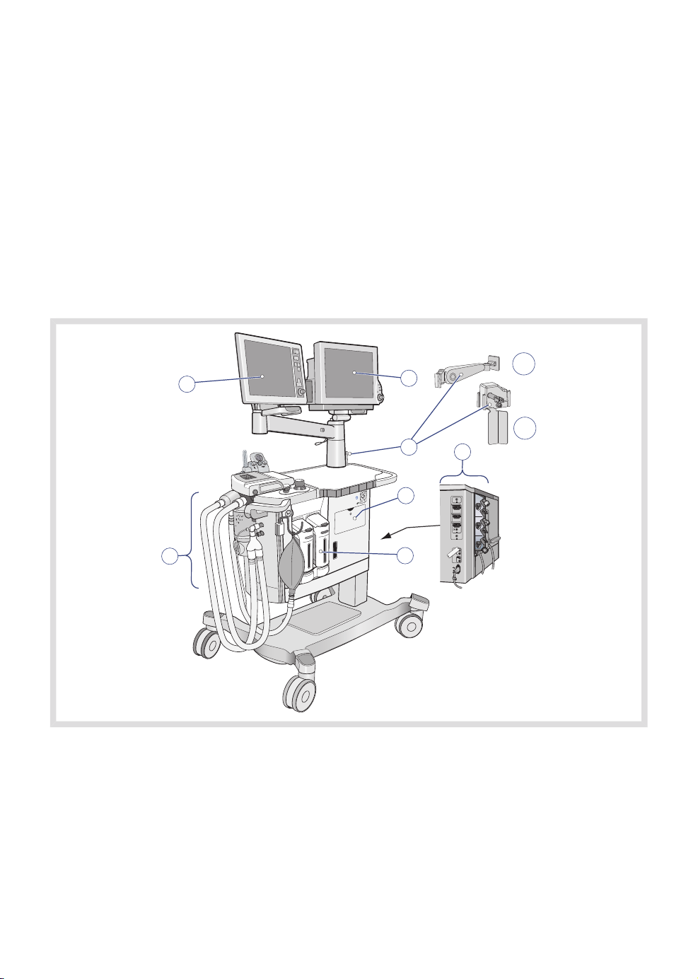
3.1 System parts
The system comprises the following basic parts:
1
7
2
3
5
220-240V~
400 VA
T 1.6 A
6
250 V
T 4 A
250 V
5. Emergency ventilation system1. Control panel
2. Patient monitor (option) 6. Vaporizer unit
7.3. Additional arm 'A' (option) and/or
Breathing system
Gas backup holder 'B' (option)
1
4. External connections
A
B
4
1. C30 can only be equipped with the additional arm or the extra backup gas holder.
18
FLOW-i 4.2, User's Manual
Page 19
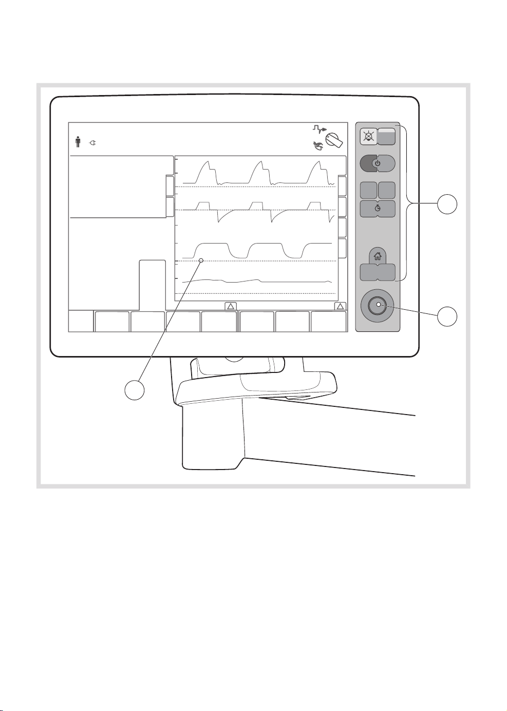
3.2 Control panel
01-01 13 00
| System overview |
3 |
312
3
2
1
The control panel includes:
1. Screen with active touch pads
2. Rotary knob
3. Membrane buttons
FLOW-i 4.2, User's Manual
19
Page 20
| System overview |
| 3
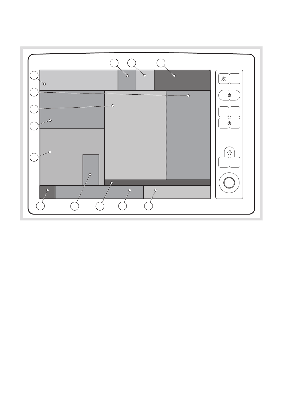
3.2.1 Areas of the screen
10
9
8
7
6
11 12 13
5 2 1
4 3
The screen is divided up into a number of different areas:
1. Ventilation direct access settings
2. Gas direct access settings
3. Activate additional settings/gas settings
window
4. Fresh gas mix rotameter
9. Tab area:
- Short trends
- Loops
- Volume Reflector Indicator
- Gas supply pressure
5. APL valve value
6. Gas measurement area
7. Ventilation measurement area
8. Waveform area
10. Current alarm and status area
11. Alarm functions
12. Timer
13. Mode indicator
20
FLOW-i 4.2, User's Manual
Page 21

| System overview |
3 |
The touch screen and rotary knob allow the
operator to control the primary functions of
the anesthesia system, where the patient's
condition is monitored through measured
values and waveform displays.
Measured values and waveforms are displayed
on the screen in the following color groups:
Color for measured values and waveforms
YellowPressure
GreenFlow
BlueVolume
2
2
Light grayCO
WhiteO
BlueN2O
GrayMAC
PurpleIsoflurane
BlueDesflurane
YellowSevoflurane
Messages are displayed in the Alarm message
area or System message area. The following
color scheme is adopted:
Color for alarms and system messages
High priority alarms
Medium priority alarms
Low priority alarms
Technical alarms, i.e.
alarms with the prefix
TEXXX, where XXX is an
integer.
System messages
Black text on red
background
Black text on yellow
background
Black text on blue
background
Black text on red,
yellow or blue
background, dependent
on priority
(high/medium/low)
White text on black
background
A detailed description of alarms and patient
safety is found in Chapter 10.
The colors for O2 and N2O in the above table
may vary due to country-specific standards.
FLOW-i 4.2, User's Manual
21
Page 22

| System overview |
| 3
3.2.2 Navigating the screen
There are several ways of navigating the
screen and setting values.
Using the touch screen
1. Press the required touch pad. The touch
pad becomes active, which is indicated
by a blue highlight.
2. Turn the rotary knob to the required value.
3. Press the touch pad to confirm setting.
An activated touch pad is only active for 20
seconds. The system will prompt the user to
enter a value when 10 seconds have passed.
If no value is entered and confirmed within the
following 10 seconds, the touch pad setting
returns to its previous setting and is
deactivated.
Using the rotary knob
1. Turn the Rotary knob to move between
the touch pads on the screen. The
selected touch pad is indicated by a blue
frame.
2. On required touch pad, press the rotary
knob to activate the touch pad. This will
highlight the touch pad in blue.
3. Turn the Rotary knob to the required
value.
4. Press the Rotary knob to confirm setting.
22
FLOW-i 4.2, User's Manual
Page 23
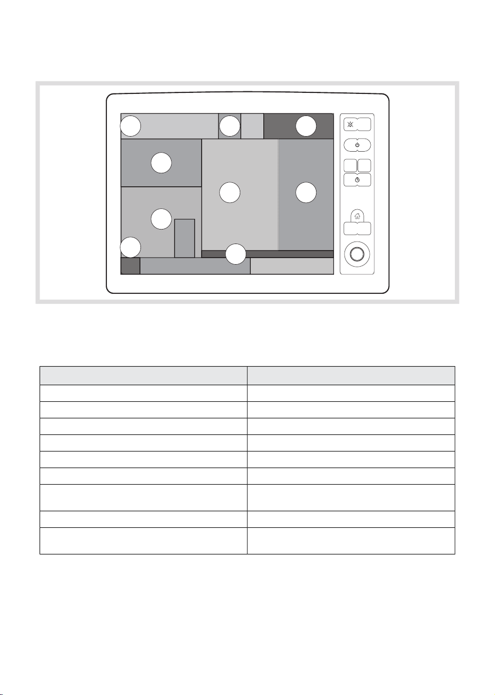
Active screen
| System overview |
3 |
5
6
4
8
3
2
Pressing any of the areas labelled with a
number in the illustration, displays a window
according to the table below.
7. Mode indicator area
9. Tab area (displayed window depends on
selected tab)
7
9
1
Dialog/window producedScreen area
Multiple windows, see Chapter 51. Gas settings/ Ventilation settings
Patient category, see Chapter 5, page 75.2. MAC value
Alarm profile window, see Chapter 10, page 187.3. Gas measurement area
Alarm profile window, see Chapter 10, page 187.4. Ventilation measurement area
Patient category, see Chapter 5, page 75.5. Patient category symbol
Alarm profile window, see Chapter 10, page 187.6. Alarm functions
Ventilation mode selection, see Chapter 5, page
87.
Waveforms and scales, see Chapter 9, page 163.8. Waveform area
- Waveforms and scales, see Chapter 9, page 163.
- Screen layout, see Chapter 9, page 163.
FLOW-i 4.2, User's Manual
23
Page 24
| System overview |
| 3
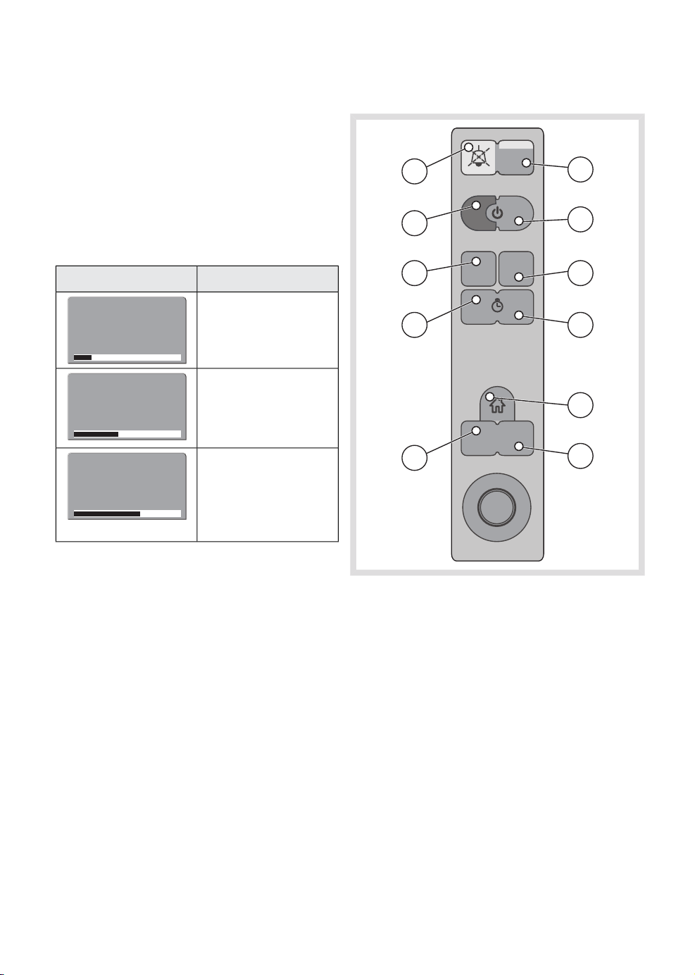
3.2.3 Touch pad settings
A range bar is located at the bottom of all
ventilation and gas touch pads, where a
numeric value can be specified by the user. If
the entered value deviates too far from the
norm given the current ventilation mode and
other parameter settings, the bar will change
color according to the table below.
DescriptionTouch pad setting
A black range bar
indicates normal
20
0 120
cmH20
50
0 120
cmH20
75
0 120
cmH20
parameter setting.
A yellow range bar
indicates that the
parameter setting is
high (or low, depending
on the parameter).
A red range bar
indicates that the
parameter setting is
very high (or very low,
depending on the
parameter).
3.2.4 Membrane buttons
1
3
5
7
10
2
4
6
8
9
11
The change in color of the range bar is
accompanied by a system message that
remains displayed on the screen until the
trigger condition is relieved.
24
1. Audio pause
2. Alarm profile
3. Start case
4. End case
5. Save screen
6. Trends
7. Start/Stop timer
8. Reset timer
9. Home
10. Screen layout
11. Menu
See Chapter 9 for more information.
FLOW-i 4.2, User's Manual
Page 25
| System overview |
3 |
3.3 Patient monitor (option)
The system can be connected to a selection
of different patient monitors. For full details,
contact your local MAQUET representative.
The patient monitor must comply with
IEC 60601-1 ed. 3.
During mains power failure, the backup battery
in the anesthesia system will not power the
patient monitor.
3.3.1 Panel interchangeability
If desired, the placement of the control panel
and the patient monitor can be switched so
that the patient monitor is placed on the
display arm. This procedure shall only be
performed by a service technician trained and
authorized by MAQUET. Contact your local
MAQUET supplier for more information.
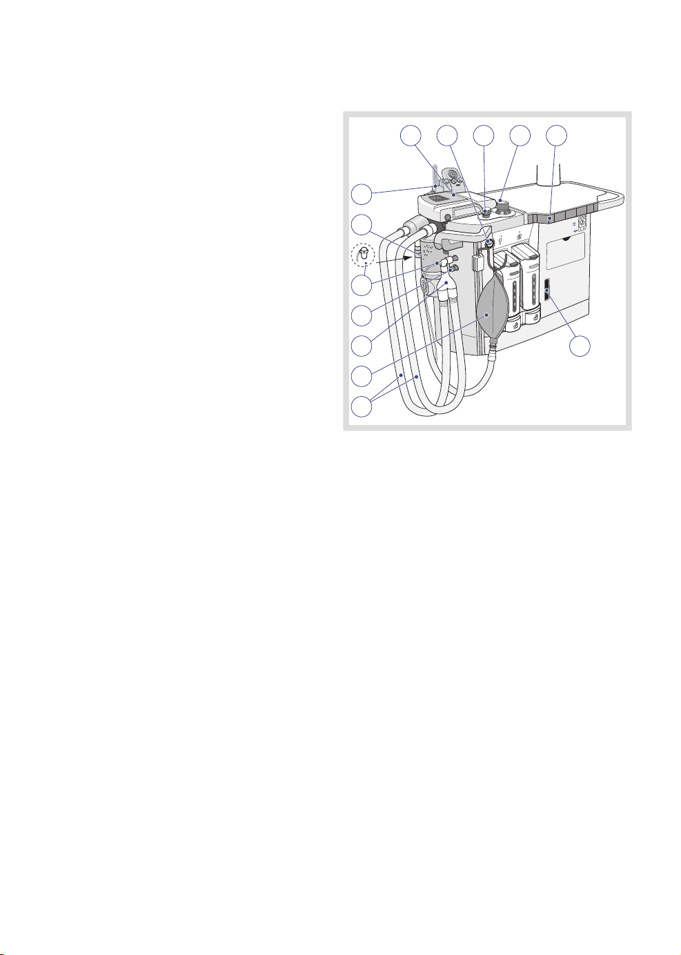
3.4 Breathing system
4
1
2
13
12
11
10
9
8
7
The breathing system comprises the following:
1. Patient cassette
2. O2 flush
3. MAN/AUTO ventilation switch
4. APL valve
5. Volume reflector
6. AGS (Anesthetic Gas Scavenging) flow
indicator
7. Patient tubing
8. Manual breathing bag with tubing
9. Y-piece
10. AFGO - Additional Fresh Gas Outlet
(option)
11. Water trap and sampling line
12. CO2absorber
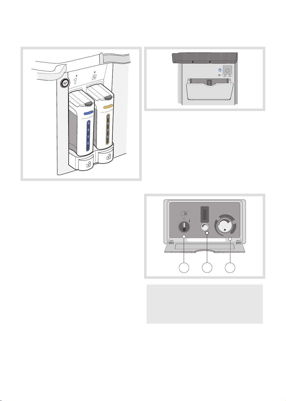
13. Auxiliary O2 and suction module (option)
53
6
FLOW-i 4.2, User's Manual
MAQUET recommends that a bacterial/viral
filter is always connected to the expiratory
connection on the patient cassette. This will
minimize the risk of cross-contamination.
25
Page 26
| System overview |
| 3
3.5 Vaporizer unit
The vaporizer unit holds one to two vaporizers,
where vaporizers can be selected for the
following agents:
• Isoflurane
• Sevoflurane
• Desflurane
3.6 Emergency ventilation system
O
2
10
8
mbar / cmH2O
6
4
2
30
I/min
Emergency ventilation
O
I/min
2
In case of a total power (i.e. mains power and
battery) or system failure, this system will allow
the patient to be manually ventilated. The
emergency ventilation system comprises:
1. Activation switch
2. O2 gas supply and flowmeter, graded up
to 10 l/min.
3. Mechanical APL
O
2
10
8
6
4
2
I/min
I/min
O
2
Not for use with AFGO
APL
80
SP
mbar / cmH2O
APL
60
26
1 3
2
WARNING! If the emergency ventilation
system is activated while the anesthesia
system is in operation, the anesthesia
system will be shutdown.
FLOW-i 4.2, User's Manual
Page 27
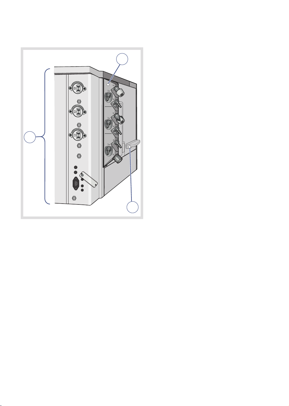
3.7 External connections
| System overview |
3 |
2
O
2
Air
1
N2O
3
The following external connections exist on
the system:
1. Power supply and fuses
2. Gas connections
3. Input/Output ports
FLOW-i 4.2, User's Manual
27
Page 28
| System overview |
| 3
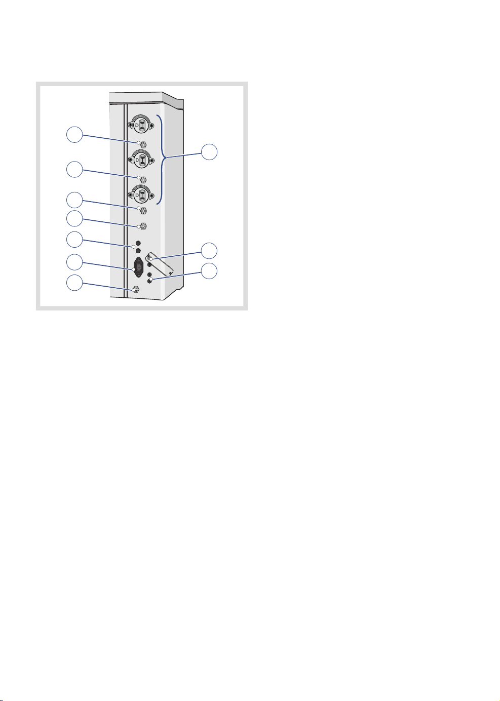
3.7.1 Power supply and fuses
1
2
3
4
5
6
7
9
8
10
1. Auxiliary power outlets fuse 2A (option)
2. Auxiliary power outlets (option)
3. Auxiliary power outlets fuse 1A (option)
4. Auxiliary power outlets fuse 1A (option)
5. Patient monitor fuse (option)
6. Isolation transformer fuse (option)
7. Mains power inlet fuses
8. Lift fuses (C30 model only)
9. Mains power inlet
10. Equipotential terminal (earth)
The patient monitor outlet and the auxiliary
power outlets do not have a battery backup.
Auxiliary power supply outlet connections vary
depending on country specific standards.
In addition to the individual fuses, the
maximum current delivered through the
system is regulated by a shared fuse.
In case of mains power failure, a battery
backup will power the system for a limited
time.
28
FLOW-i 4.2, User's Manual
Page 29
| System overview |
3 |
WARNING!
Restrictions apply to the use of auxiliary
power outlets:
• Outlets must not be used to power life
support equipment unless the life support
equipment itself is equipped with battery
backup.
• A multiple socket extension cord must
not be connected to any of the outlets.
CAUTION: The auxiliary power outlets shall
only be used for supplying power to
equipment intended to form part of the
medical electric system.
For more details on the power supply and
status, see Chapter 10, page 203.
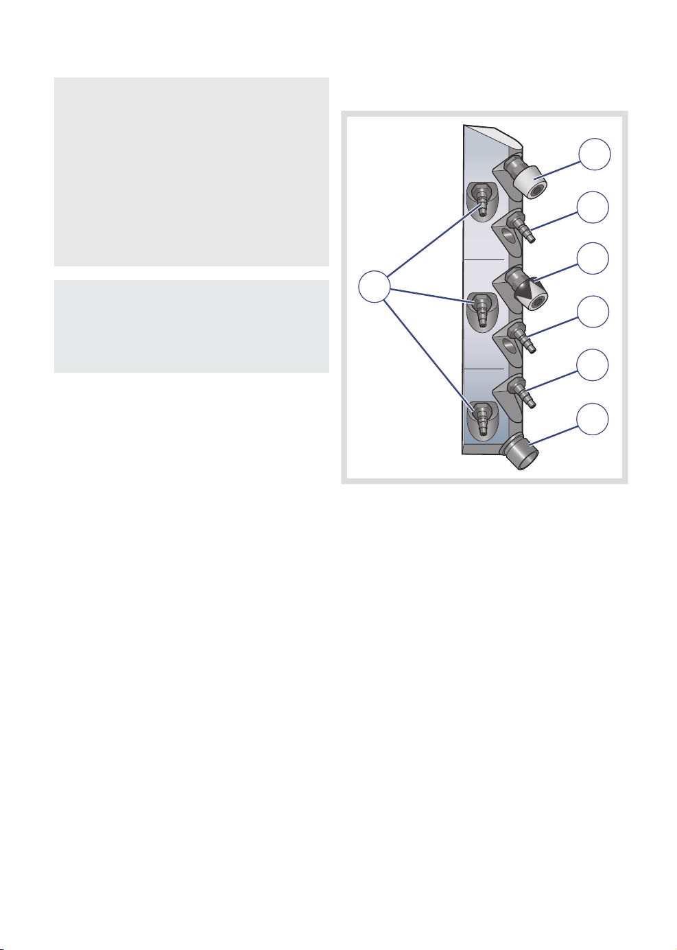
3.7.2 Gas connections
1
2
3
7
4
5
6
FLOW-i 4.2, User's Manual
1. O2 outlet (option)
2. O2 inlet
3. Air outlet (option)
4. Air inlet
5. N2O inlet
6. AGS outlet (country-specific connections)
7. Gas cylinder inlets for O2, Air and N2O
(option)
If equipment with high gas consumption are
connected to the gas outlets, the central gas
supply pressure should be above 3 bar (300
kPa, 44 PSI). Make sure that the central gas
supply is sufficient for the extra equipment.
29
Page 30
| System overview |
| 3
The intended use for the Auxiliary O2 outlet is
to provide oxygen for patient therapy.
The intended use for the Auxiliary AIR outlet
is to provide drive gas for small ejector driven
suction devices.
Maximum allowed air flow from each of the
O
and Air outlets is 60 l/min.
2
The central N2O gas supply (wall supply) is
connected to the system via a pressure
regulator attached to the N2O gas inlet.
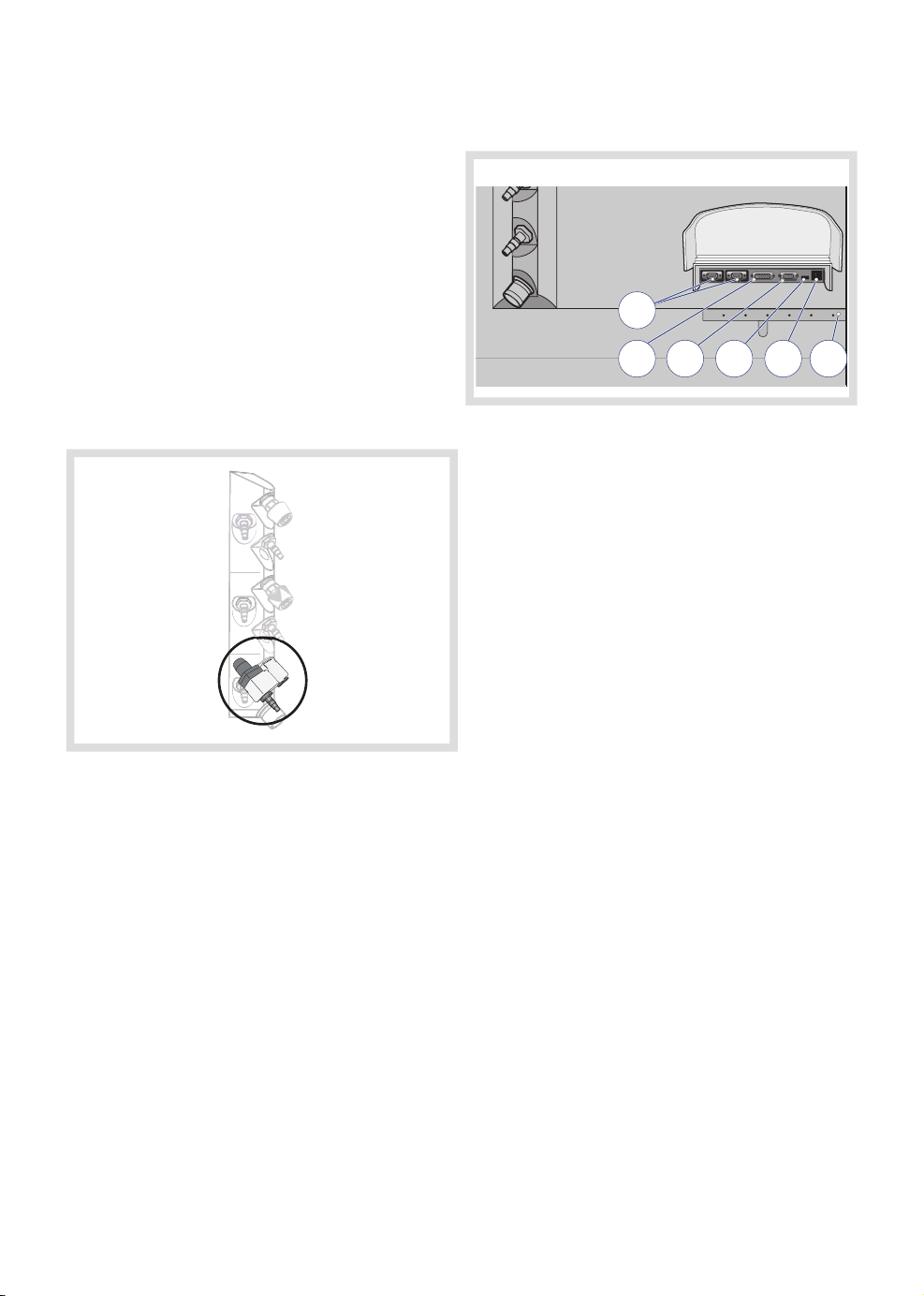
3.7.3 Input/Output ports
1
2 3 4
1. RS232 serial data communication ports
2. Control panel connection
3. VGA connector
4. USB port
5. Network connection
6. Cable restrainer
The intended use of the USB port is only for
USB memory flash drives. Restricted items
include, but are not limited to, external hard
drives, USB hubs and any equipment using
the USB port primarily as a power source.
6
5
Clinical situations that require high gas
consumption might affect the supply gas
pressure.
If the gas supply is low, i.e. close to 2.5 bar
(250 kPa, 36 PSI), the system's ability to
deliver gas according to all possible settings
might be compromised by additional gas
hoses and connections.
30
FLOW-i 4.2, User's Manual
Page 31

The network connection (LAN) port is for
service use, and should only be used by
personnel trained and authorized by MAQUET.
External cables connected to the I/O ports
must be secured using cable restrainers where
available.
CAUTION: The operator must not touch
any of the input/output ports, e.g. RS232,
VGA connector and USB port, and the
patient simultaneously.
| System overview |
3 |
FLOW-i 4.2, User's Manual
31
Page 32

Y
SN
| System overview |
| 3
3.8 Explanation of symbols
3.8.1 Labels
The following symbols are shown on the
system:
DescriptionSymbol
CE label. The device complies
with the requirements of the
0123
C US
European Council Directive
93/42/EEC (i.e. the Medical
Device Directive).
CSA label—Indicates compliance
with Canadian and US standards
Manufacturer
Manufacturing date
2012
UDI Label - Unique Device
Identification. See technical
specifications, page 290.
Class 1 equipment, Type B. The
device classification according
to IEC 60601-1.
Federal law restricts this device
Rx
to sale by or on the order of a
physician.
ONL
IP classification: IPX1, drip proof
IPX1
SN
LOT
DescriptionSymbol
Worn-out batteries must be
recycled or disposed of properly
in accordance with appropriate
industrial and environmental
standards.
White drawing on a blue
background. Consulting
accompanying documentation is
a mandatory action.
Indicates instructions that must
be followed in order to ensure
the proper operation of the
equipment.
Use by date
Black cross over an orange
background. Broken CO
absorber canisters may cause
skin irritation.
Use no oil. Applicable to parts
marked with this symbol.
Serial number
Batch code
Article number
Do not use if packaging is
damaged
2
32
Pb
Black border, black exclamation
mark over a yellow background.
Indicates critical information
about a potentially serious
outcome to the patient or the
user.
Special waste to be disposed of
in accordance with appropriate
industrial and environmental
standards.
Caution must be taken when
moving the system up or down
a slope. Refer to Transport
conditions, page 38.
FLOW-i 4.2, User's Manual
Page 33

| System overview |
3 |
<
2
365 kg
DescriptionSymbol
Medical device maximum weight
(C20 with three drawers). C30
and C40 are lighter, see
technical specifications, page
266.
Red circle with a single red line
over a black drawing. Pushing
prohibited
Red circle with a single red line
over a black drawing. Stepping
prohibited
Red circle with a single red line
over a black drawing. Sitting
prohibited
Lift button, 10% lift dutycycle,
for more information see Chapter
18
>
7, page 146.
Manual (MAN) ventilation
Autoclavable
DescriptionSymbol
CO2 absorber connected and
locked in position
CO2 absorber bypassed
CO2 absorber unlocked,
vaporizer unlocked,
patient cassette unlocked,
wheel brake unlocked
Wheel brake locked
Labelled part may be disinfected
using a steam autoclave
Use centre of floating ball as
reference when reading from the
Auxiliary O
flow scale
2
Inspiratory connection to the
patient cassette
FLOW-i 4.2, User's Manual
Automatic (AUTO) ventilation
Manual breathing bag
connection
Y-piece connection for System
checkout
Equipotentiality terminal.
Mains power On Off button
Insp.
Expiratory connection to the
patient cassette
Exp.
O2 flow meter/suction equipment
O2 flush
02 +
Anesthesia Gas Scavenging
AGS
Home touch pad symbol, see
Chapter 9, page 162
33
Page 34

| System overview |
| 3
Emergency
ventilation
Not for use with AFGO
N O
2
2 . 5 - 6.5 k Pa x 10 0
( 3 6 - 94 p s i )
DescriptionSymbol
Timer touch pad symbol, see
Chapter 9, page 162
Emergency ventilation
Not for use with AFGO.
Emergency O
flow is always
2
delivered through the patient
cassette.
N2O inlet pressure range:
250-650 kPa/2.5-6.5 bar/36-94
PSI
AFGO Max 120 mbar/cmH2O
Reading lamp
Cylinder gas inlet
DescriptionSymbol
Data communication
input/output ports
Fuse
Control panel connection
VGA connection
USB connection
RS232
34
Backup gas system pressure
increase/decrease
RS232 serial port
Gas supply inlet
Gas supply outlet
Network connection
FLOW-i 4.2, User's Manual
Page 35

2
| System overview |
3 |
3.8.2 Screen-displayed symbols
The following symbols are shown on the
screen:
DescriptionSymbol
Standby mode
Active alarm
Multiple active alarms
Audio pause, pre-mute alarm,
mute active alarm or remove
resolved alarms.
Audio off
Alarm off
Power indicator - indicates AC
power connected
Infant
+
60
58
2:00
88 min
DescriptionSymbol
Overlay loops
Numerical trends selected
Graphical trends selected
Activates a cursor in the trends
display window, and allows for
use of the rotary knob to scroll
through values.
Checkbox - can be selected to
mark an option or to choose a
feature for display on the screen
Gas analyzer has no information
to display
Audio pause—silence or confirm
an alarm
Power indicator - indicates
battery operation, along with
estimated time remaining
R
FLOW-i 4.2, User's Manual
Adult
Ventilation mode indicator
Manual ventilation selected
Automatic ventilation selected
Reference loop
Timer activated
02:35:10
Date and time
08-19 16 04
35
Page 36

| System overview |
| 3
3.9 Ergonomical positioning
• The C20 and C30 systems are on wheels
and can be rotated 360°.
• The C40 system is mounted onto a ceiling
pendant and can be moved and rotated as
allowed by the pendant solution.
• The control panel can be tilted up and down
15° and rotated 220° (without moving the
display arm).
• The display arm can be rotated 170°.
• The height of the C30 working surface can
be set anywhere between approx. 30 in.
and 40 in.
3.9.1 Using the brake
Once a suitable position has been found, the
wheels should be locked into position.
1 2
1. Push the brake down to lock the wheel.
2. Push the brake up to unlock the wheel.
CAUTION: Be careful when moving the
display arm to avoid damaging equipment
placed on the writing table or top shelf.
36
FLOW-i 4.2, User's Manual
Page 37

3.9.2 Working position
The flexibility of the system allows the operator
many alternative working positions:
Examples of working positions
| System overview |
3 |
FLOW-i 4.2, User's Manual
37
Page 38

| System overview |
| 3
3.10 Storage and transportation
3.10.1 Before transport
• If the system is to be moved to another
room or transported a longer distance,
ensure mounted accessories are securely
attached to the system.
• The C40 system is intended for transport
inside the operation room only when
undocked from the ceiling pendant.
Transportation to other locations requires
the use of a suitable cart or trolley
according to hospital routines.
CAUTION: Make sure extra equipment and
accessories, e.g. support arm and
additional table, are folded close to the
system during transport to minimize the risk
of tipping. The display arm should be
positioned as shown in the illustration.
3.10.2 During transport
• Move the system using the handles on the
main unit and not those on the control panel
or patient monitor. This will reduce the risk
of tipping and/or system damage.
• If the optional extra table is installed, make
sure it is folded into a vertical position.
• Be careful when moving the system down
a slope.
38
FLOW-i 4.2, User's Manual
Page 39

3.10.3 Storage
• During storage keep the system connected
to the mains power supply so that the
batteries maintain a full charge.
• If the system is disconnected from a power
source, ensure the batteries are fully
charged before storage to avoid
deterioration of battery performance.
• When the system is disconnected from a
mains power supply, a fully charged battery
can be stored in the FLOW-i system for up
to six weeks at temperatures between +5°C
(+40°F) and +40°C (+105°F). At
temperatures between +50°C (+125°F) and
60°C (+140°F) storage time is one week. If
these limits are exceeded, battery
performance can no longer can be
guaranteed.
• MAQUET recommends that the vaporizers
are emptied before long term storage (>30
days).
• For fire safety purposes, the system
requires functional batteries for system
Startup.
• Ensure the system is not exposed to
temperatures below -25oC (-13oF) or above
+60oC (140oF).
• For information on CO2 absorber storage,
see Chapter 7, page 128.
• Ensure the system is not exposed to a
relative humidity above 95%.
| System overview |
3 |
FLOW-i 4.2, User's Manual
39
Page 40

1
2
1
2
1
2
| System overview |
| 3
3.11 System models
The anesthesia system is available in different
models:
• C20
• C30
• C40
The following table shows the standard
equipment for these different models (main
components):
C40C30C20
• Working surface/writing table
• Reading lamp
• Two drawers, one lockable
• Battery for approx. 90 minutes
support (fully charged)
• Vertical shafts for optional
horizontal rails
• Four wheels with individual
locking brake
40
• Height adjustable
• Working surface/writing table
• Reading lamp
• One lockable drawer
• Battery for approx. 90 minutes
support (fully charged)
• Vertical shafts for optional
horizontal rails
• Four wheels with individual
locking brake
• Ceiling pendant
• Working surface/writing table
• Reading lamp
• One lockable drawer
• Battery for approx. 90 minutes
support (fully charged)
• Vertical shafts for optional
horizontal rails
FLOW-i 4.2, User's Manual
Page 41

| System overview |
3 |
3.12 Optional equipment
Not all listed optional equipment may be
available in your country, contact your local
MAQUET representative for more information.
3.12.1 Vaporizer holder
The vaporizer holder provides easy access to
an additional vaporizer during surgical
procedures.
The vaporizer holder may only be installed or
moved by a service technician trained and
authorized by Maquet.
FLOW-i 4.2, User's Manual
Attaching a vaporizer
A
Slide the vaporizer into the slot until the front
locks into place (A).
To remove the vaporizer, lift up the front and
gently pull outwards.
41
Page 42

| System overview |
| 3
3.12.2 Universal bracket for C20
The universal bracket for C20 is intended for
use with the FLOW-i C20 model only. It
provides additional space for mounting
accessory equipment.
3.12.3 Manual breathing bag support arm
The support arm provides a static and secure
support for the manual breathing bag and
associated tubings.
The support arm shall only be used to secure
the manual breathing bag and associated
tubings.
The universal bracket is permanently attached
to the core unit, and shall only be removed by
a service technician trained and authorized by
MAQUET.
Maximum dimensions of mounted equipment
is approximately 430x340x180 mm (WxHxD).
Always ensure mounted equipment is properly
secured before starting a patient case.
42
Connection
A
The support arm is fastened to the vertical
railing on the core unit by turning the fastening
knob (A).
FLOW-i 4.2, User's Manual
Page 43

| System overview |
3 |
3.12.4 EVAC Restrictor
The EVAC restrictor acts to reduce the
pressure difference between high vacuum
evacuation systems and the FLOW-i AGS
outlet. This ensures proper gas evacuation
without adverse side effects.
The EVAC restrictor may only be installed by
a service technician trained and authorized by
Maquet.
AGS hose assemblies connected to the
system shall comply with ISO 80601-2-13.
If equipped with alternate connector systems,
the connectors shall comply with DISS:
CGA-V5:2008 (WAGD), SS 875 24 30:2004
(UTS).
Restrictor unit
3.12.5 Cable support arm
To organize and manage cables connecting
the patient to the patient monitor, a cable
support arm can be attached to any of the
system's four vertical shafts.
The arm can be bent and angled to provide
the most suitable cable arrangement. Ensure
that the emergency ventilation hatch is not
obscured by the cable support arm.
A
The apropriate evacuation flow is achieved by
turning the adjusting knob (A), so that the
evacuation floater in the AGS flow meter
hovers above the dashed area. This ensures
sufficient evacuation flow.
FLOW-i 4.2, User's Manual
The cable support arm is to be used for
electrical cables only. It shall not be used for
patient tubings or any other equipment.
The maximum load is 1.1 lbs.
43
Page 44

| System overview |
| 3
3.12.6 Top shelf
The top shelf is attached to the display
column. Various types of equipment, e.g.
parameter box and patient monitor, can be
used in combination with the shelf.
20”
CAUTIONS:
• The maximum load of the top shelf is 20
kg. Applies to all system models.
• The size and placement of equipment
mounted on the top shelf must be
constrained to the following dimensions:
- Height: 20 in.
- Width: 14 in.
- Depth: 18 in.
• Ensure that equipment mounted on the
top shelf is properly fastened.
• Be aware of equipment mounted on the
top shelf when moving the display arm.
The top shelf, along with any associated
equipment, shall be assembled by a hospital
technician.
44
FLOW-i 4.2, User's Manual
Page 45

| System overview |
3 |
3.12.7 Vaporizer slot cover
The vaporizer slot cover is intended to protect
the gas and electrical connections inside the
vaporizer slot when no vaporizer is connected.
1 2
Slide the cover at a slight angle into the vacant
vaporizer slot until it locks into place..
3.12.8 Backup gas system
The backup gas rack and backup gas cylinder
holder are described in Chapter 10, page 204.
FLOW-i 4.2, User's Manual
45
Page 46

| System overview |
| 3
46
FLOW-i 4.2, User's Manual
Page 47

4 Startup and system checkout Table of contents
| Startup and system checkout |
48|System startup4.1
49|System checkout4.2
59|Leakage check4.3
60|Vaporizer check4.4
61|Understanding results4.5
62|Standby mode4.6
63|Start case4.7
64|Emergency ventilation4.8
4 |
FLOW-i 4.2, User's Manual
47
Page 48

| Startup and system checkout |
| 4
4.1 System startup
• Start the system by means of the Power
button found directly above the Emergency
ventilation system.
48
FLOW-i 4.2, User's Manual
Page 49

| Startup and system checkout |
4 |
4.2 System checkout
01-01 13 00
1 2
A prompt to start the System checkout
procedure is automatically displayed at system
startup:
1. Bypass the System checkout
2. Start the System checkout
To ensure correct system functionality, optimal
performance and patient safety, the System
checkout procedure must be performed as
follows:
• Once a day, or before connecting the first
patient within a running 24 hour period.
• After replacing the patient cassette.
• After the system has been transported.
If the system needs to be used immediately,
i.e. during an emergency, values and results
from the last successful System checkout
remain in effect.
Press the Start touch pad in the System
checkout window to begin the procedure.
The System checkout can also be initiated via
the Menu membrane button during Standby,
see Chapter 9, page 166.
The procedure includes the following main
areas:
• Preparations
• Checks requiring user interaction
• Automatic checks
FLOW-i 4.2, User's Manual
49
Page 50

| Startup and system checkout |
| 4
4.2.1 Preparations
01-01 13 00
1
2
3
The first part of the System checkout
procedure ensures that the system is correctly
prepared for use.
4
5
6
7
8
9
An in-depth description of the different steps
is presented in the table on page 52.
Check the components listed on the screen
and press the 'Continue' touch pad located
in the bottom right of the screen when
finished.
50
FLOW-i 4.2, User's Manual
Page 51

| Startup and system checkout |
4 |
If an external Patient Gas Analyzer is used (not
the one in FLOW-i), the sampling has to be
switched off in order not to remove gas from
the system. The Leakage check may otherwise
fail.
If the system has backup cylinders installed,
an extra check point appears on the screen.
Make sure these cylinders are open for the
duration of the System checkout.
If only the O
backup gas cylinder is used, the
2
Air and/or N2O backup gas cylinder pressure
check can be disabled in Service and Settings
– Startup configuration, see Chapter 9, page
178.
If any of the connected vaporizers contain
<5% of the total agent volume, the automatic
vaporizer test will not be initiated for that
vaporizer. A prompt window appears. Pressing
'bypass test' will exclude that vaporizer from
the check. Pressing 'redo test' will repeat the
test.
4.2.2 Gas sampling leakage
The 'sampling leakage alarm' responds to
amounts of leakage sufficient to interfere with
the gas sampling precision.
If the alarm is activated, perform any or all of
the following actions before contacting Maquet
service:
• Check the sampling line connections
• Check the patient tubing connections
• Replace the patient cassette
FLOW-i 4.2, User's Manual
51
Page 52

| Startup and system checkout |
| 4
Additional descriptionPreparatory steps
Step 1
Check that the breathing circuit is correctly
mounted and connected to the test plug (A).
Step 2
Check the water trap and sampling line.
Discard/empty any water present in the water trap.
A
Step 3
Check that the absorber is correctly mounted and
unsaturated. Also check that the switch is in the
'locked' position.
52
FLOW-i 4.2, User's Manual
Page 53

Step 4
Check that the vaporizer(s) contains sufficient
agent.
| Startup and system checkout |
4 |
Additional descriptionPreparatory steps
max
max
Step 5
Check that the Anesthesia Gas Scavenging (AGS)
flow indicator is above the dashed area.
CAUTION: Ensure that the AGS is correctly
connected. Running the system with a poor AGS
connection may result in anesthetic agent being
emitted into the operation environment.
Step 6
Check that the central gas supplies are connected.
min
min
FLOW-i 4.2, User's Manual
53
Page 54

| Startup and system checkout |
| 4
Step 7 (only if backup cylinders are installed)
Check that the Backup cylinders are opened. Close
the cylinders after completing System checkout.
The system checkout will not initiate if the system
is not connected to the central gas supply.
WARNING! If the backup gas supply pressure
is higher than the central gas supply pressure,
the backup cylinder gas will be used during the
System checkout. Make a note of the backup
cylinder pressure presented on the Control Panel
screen during the System checkout.
Additional descriptionPreparatory steps
Step 8
Check that the manual resuscitator is readily
available and is working correctly.
Step 9
Check for adequate suction pressure in the suction
unit and that the auxiliary O
flow is functioning
2
properly, refer to Chapter 7, page 129, for
instructions.
54
FLOW-i 4.2, User's Manual
Page 55

4.2.3 Checks requiring user interaction
A
B
| Startup and system checkout |
01-01 13 00
3
2
1
2
1
4 |
The second part of the System checkout
procedure requires the user to perform a few
actions before proceeding to the next step:
A. Manually test the O2 flush:
• Press the 'Start check' touch pad.
• Fully depress the O2 flush button for
approx. 3 seconds. If the test is
successful, 'Passed' appears on the
panel screen. Continue to the next step
(B). Otherwise repeat the test.
FLOW-i 4.2, User's Manual
B. Inspect the function of the inspiratory and
expiratory unidirectional valves (some
systems may be fitted with a patient
cassette lid that needs to be opened to
see the valves):
• If necessary, open the patient cassette
lid.
• Press 'Start check' and ensure that the
unidirectional valves are moving up and
down.
• Confirm by pressing 'Yes' on the panel
screen prompt.
• If necessary, close the patient cassette
lid and press 'Continue' or simply press
'Continue' to move on to the next step.
55
Page 56

| Startup and system checkout |
| 4
4.2.4 Automatic checks
01-01 13 00
1
The third part of the System checkout
procedure contains a number of tests that the
system automatically performs. These are as
follows:
• Internal tests
• Barometer
• Gas supply pressure
• Pressure transducers
• Safety valve
• Vaporizer inlet/outlet valve
• Flow transducer
• AUTO ventilation leakage
• MAN ventilation leakage
• Gas analyzer
• Battery
• Vaporizer 1
• Vaporizer 2
• Technical alarms
Components listed on the screen are
individually tested. 'Passed' (in green text) or
'Failed' (in red text) is displayed after each test
depending on the outcome. 'Running'
indicates the test currently being performed.
If the gas analyzer test fails, the vaporizer tests
will not be performed. A dialog box will appear
to inform the user of this.
The automatic check procedure ends when
all tests are performed. This procedure can at
any time be bypassed by pressing the Bypass
touch pad located in the lower left area of the
panel screen (1).
The current leakage for manual and automatic
ventilation is displayed separately in ml/min.
A maximum leakage of up to 150 ml/min is
allowed for each of the ventilation modes. The
leakage tests are performed using a pressure
of 50 cmH2O and 30 cmH2O for AUTO and
MAN ventilation mode respectively.
Some automatic tests can be repeated after
the automatic test sequence has finished; a
prompt to check the relevant part and redo
check appears on the screen.
56
FLOW-i 4.2, User's Manual
Page 57

| Startup and system checkout |
4 |
If only the O2 backup gas cylinder is used, the
Air and/or N
O backup gas cylinder pressure
2
check can be disabled in Service and Settings
– Startup configuration, see Chapter 9, page
178.
Circuit compliance compensation is calculated
during the leakage tests and presented with
the test results.
If N2O central gas supply pressure is
connected while the N2O function is
deactivated, the system checkout will fail.
WARNING! If the System checkout is
unsuccessful, the system must not be
connected to the patient until the
malfunction is corrected. If the malfunction
cannot be corrected by the operator, the
system must be turned Off, taken out of
operation and serviced by personnel trained
and authorized by MAQUET.
4.2.5 Finalization
01-01 13 00
1 2 3
Once all checks are completed, a summary is
displayed on the screen. Press the Standby
touch pad located at the bottom right of the
screen to enter Standby mode.
Checks can be repeated by pressing any of
the touch pad buttons located in the bottom
left area of the panel screen:
FLOW-i 4.2, User's Manual
1. Redo System checkout
2. Redo leakage check
3. Redo vaporizer check
57
Page 58

| Startup and system checkout |
| 4
These checks can also be initiated in Standby
mode via the Menu membrane button.
The results of each test in the System
checkout procedure can also be viewed by
pressing the 'Results' touch pad in the
Standby mode main screen, or by accessing
the System checkout sub-menu via the Menu
membrane button.
CAUTION: Close the backup cylinders after
completing the System checkout to avoid
unintentional use or leakage of the backup
gas.
4.2.6 Bypassing System checkout
In emergencies, the System checkout can be
bypassed at any stage of the procedure. This,
however, is not recommended.
With an emergency startup situation, Manual
ventilation and fresh gas dosage are ready for
use within 15 seconds. Monitored parameters
have full accuracy after a maximum of 15
minutes. However, pressure, flow and volume
displays will be 90-95% accurate after approx.
two minutes.
If the system is still warm, full accuracy is
obtained much more quickly.
If the System checkout is bypassed, the
default system value (without patient tubing)
for circuit compliance compensation will be
used.
58
FLOW-i 4.2, User's Manual
Page 59

| Startup and system checkout |
4 |
4.3 Leakage check
Performs a Leakage check of the manual and
automatic breathing circuits. It shall be
performed after each change of tubings,
breathing bags or filters.
01-01 13 00
1 3
2 4
Leakage check preparatory phase contains
four steps, equivalent to steps 1, 2, 3 and 6
performed during the Full system check, see
section 4.2.1.
The automatic check sequence includes
automatic and manual breathing circuit
leakage checks.
01-01 13 00
1 2 3
A summary of the results is displayed after the
automatic check. Press the Standby touch
pad to enter Standby mode or press any of
the touch pads marked 1-3 to repeat any of
the checks.
The circuit compliance compensation is
re-calculated during the Leakage check and
the log is updated with the new measured
values for leakage.
FLOW-i 4.2, User's Manual
59
Page 60

| Startup and system checkout |
| 4
4.4 Vaporizer check
Performs a leakage check of the manual and
automatic breathing circuits and a check of
vaporizer functionality. It shall be performed
after a vaporizer has been connected to the
system.
The first part is identical to the Leakage check
and is made to ensure that no agents leak out
into the operating room during Run mode.
01-01 13 00
1
4
5
2
6
3
01-01 13 00
1 2 3
The automatic check sequence includes
vaporizer checks in addition to the automatic
and manual breathing circuit leakage checks.
A summary of the Leakage check and the
Vaporizer check results is displayed after the
automatic check. Press the Standby touch
pad to enter Standby mode or press any of
the touch pads marked 1-3 to repeat any of
the checks.
Vaporizer check preparatory phase contains
six steps, equivalent to steps 1 to 6 performed
during the Full system check, see section
4.2.1.
If any of the connected vaporizers contain
<5% of the total agent volume, the automatic
vaporizer test will not be initiated for that
vaporizer. A prompt window appears. Pressing
'bypass test' will exclude that vaporizer from
the check. Pressing 'redo test' will repeat the
test.
60
When the vaporizer is connected and active,
the Agent concentration touch pad displays
the name of the agent, and the agent
concentration is by default set to OFF.
FLOW-i 4.2, User's Manual
Page 61

| Startup and system checkout |
4 |
4.5 Understanding results
01-01 13 00
1
32
In Standby mode, the central area of the
screen displays the result of performed system
checks, along with date, time and outcome.
The symbol (1) can be either green, yellow or
red, depending on the current status of system
checkouts. A detailed view is obtained by
pressing 'View results' (2). A full system
checkout, leakage check or vaporizer check
is initiated by pressing the corresponding
touch pad (3).
Patient cases should not be started if only
Leakage or Vaporizer checks have been
performed since system startup or during the
last 24 hours period.
Press the 'Results' touch pad to display a
window describing the system checkout
results in more detail.
Symbol color codes correspond to the
following:
Passed. A patient case can be
started.
FLOW-i 4.2, User's Manual
More than 24 hours since a
successful full system checkout
was performed. Perform a System
checkout.
Not performed. A patient case
can be started, but this is not
recommended. Perform a System
checkout.
Red symbolYellow symbolGreen symbol
Failed. One or several checks
failed during the System
checkout/Leakage
check/Vaporizer check. Make
appropriate adjustments and redo
check.
61
Page 62

| Startup and system checkout |
| 4
4.6 Standby mode
01-01 13 00
The Standby screen provides a summary of
the System status, the current gas/ventilation
settings and the selected ventilation mode. If
a vaporizer is connected and selected, the
name of the agent is presented on the screen.
Listed below are examples of functions that
can be performed in Standby mode either by
pressing the active touch pads, or by
accessing the menu using the Menu button.
If the System checkout was bypassed, or if
the System checkout failed, a corresponding
system message will be displayed in the
message area.
When a patient case is started using AUTO
ventilation or a switch is made during Run
mode to AUTO ventilation, the preset gas and
ventilation settings are activated.
• The gas and ventilation settings can be
preset before starting a patient case.
• Define patient settings.
• Any or all system checks can be started;
System checkout, Leakage test and
Vaporizer test.
• The Service and settings menu can be
accessed.
• A patient case can be started.
• Alarm limits can be preset before starting
a patient case.
• Test results of the latest performed checks
can be reviewed by pressing the results
touch pad.
62
FLOW-i 4.2, User's Manual
Page 63

| Startup and system checkout |
4 |
4.7 Start case
Once a successful system checkout has been
performed, the system is ready to start a
patient case. Customize the case by defining
patient category, ventilation mode, ventilation
mode settings, and alarm limits. Press the
'start case' membrane button to start the case.
See Chapter 9, page 157, for more information.
Patient category selection is described in
Chapter 5, page 75.
Ventilation mode selection and parameter
settings are described in Chapter 5.
Alarm limit settings are described in Chapter
9, page 187.
WARNING! Ensure that all alarm limits and
ventilator settings are appropriately set
before connecting the system to the patient.
4.7.1 Compliance compensation
Part of the volume of each inspiration will not
reach the patient because of gas compression
in the anesthesia system and expansion of the
tubing. All components in the patient circuit
affect such losses.
When compliance compensation is calculated,
the delivered and measured volume and flow
values are automatically compensated for
these losses. The leakage test must be passed
in order for the system to calculate correct
compliance compensation. If the leakage test
is not passed, the default system value
(without patient tubing) for circuit compliance
compensation will be used.
The compliance compensation calculations
are made based on the current set-up of the
system, and are subject to changes to the
breathing system volume.
FLOW-i 4.2, User's Manual
These calculations become obsolete when,
for example, patient tubings are changed (e.g.
from adult to infant), or if additional equipment
is installed which increases the breathing
system volume.
Update the system by performing a new
leakage check to ensure correct delivery of
gas flow.
63
Page 64

| Startup and system checkout |
| 4
4.8 Emergency ventilation
4.8.1 Manual check of Emergency
ventilation system
To test its operation, perform the following:
1. Activate the Emergency ventilation system
using the activation switch for emergency
ventilation.
2. Set the O2 flow to 10 l/min - the current
flow is indicated on the flowmeter when
the center of the ball is aligned with the
printed scale.
3. Check at various APL settings that the
test lung can be ventilated using the
Manual breathing bag.
O
2
10
8
mbar / cmH2O
6
4
2
I/min
APL
If the emergency ventilation is activated, either
during a patient case or when testing the
system, the emergency ventilation APL valve
must be set to minimum before resuming
normal ventilation (AUTO or MAN) or starting
a new patient case.
CAUTIONS:
• The emergency flow is always delivered
via the patient cassette outlet and thus
the patient tubings must always be
connected to patient cassette outlets
when emergency ventilation is used.
• Staff working with the system should
practise regularly using the emergency
ventilation system.
64
I/min
O
2
Not for use with AFGO
1 3
2
FLOW-i 4.2, User's Manual
Page 65

5 System functionality Table of contents
| System functionality |
66|FLOW-i Anesthesia system5.1
74|Patient settings5.2
79|Fresh gas flow settings5.3
83|Ventilation settings5.4
104|Measured values5.5
107|Waveform area5.6
114|Inspiratory and expiratory hold5.7
117|Miscellaneous5.8
5 |
FLOW-i 4.2, User's Manual
65
Page 66

| System functionality |
| 5
5.1 FLOW-i Anesthesia system
The FLOW-i is a software controlled circle
system for anesthesia. It features several
components distinguishing it from other
anesthesia systems; gas modules regulating
fresh gas flow, the volume reflector and the
injector based vaporizer.
The volume reflector replaces the 'bag in
bottle' used in many traditional systems. It has
a fixed volume of 1.2 liters and no moving
parts. Gas flow is regulated by the reflector
gas module. This facilitates precise control of
gas flow and pressure during automatic
ventilation.
The Vaporizer works with an electronic based
injector technology capable of operating at
low tidal volumes. This allows for fresh gas to
be led directly through the vaporizer chamber
and be mixed with the anesthetic agent.
Changes made in agent concentrations will
therefore be instantaneous. The vaporizer
technology also enables high agent
concentrations at high fresh gas flows, i.e. up
to 20 l/min.
5.1.1 Tidal volume delivery
The tidal volume delivered to the patient
comes from two sources: the fresh gas flow
and exhaled gas in the volume reflector
pushed back towards the patient by the
reflector gas module. Refer to page 72 for a
schematic view.
When the part of the tidal volume delivered
from the volume reflector exceeds one litre,
gas from the reflector gas module may pass
through the volume reflector and add oxygen
to the breathing system. This will trigger the
'Leakage' alarm.
In these situations, the oxygen concentration
will increase and the agent concentration will
decrease. However, ventilation will always be
maintained.
The situation can be corrected by increasing
the fresh gas flow.
Carefully monitor displayed gas measurements
when using low fresh gas flow settings and
high tidal volumes.
66
FLOW-i 4.2, User's Manual
Page 67

5.1.2 Low flow anesthesia
The use of oxygen as the drive gas in the
volume reflector diminishes the risk for hypoxia
should a leakage occur during low, or minimal
flow anesthesia. However, should a leakage
occur (the source of which is either known of
unknown), then the volume reflector always
ensures ventilation (it will never collapse like
a bellows).
A leakage moves the borderline between
exhaled gas and oxygen towards the breathing
circuit, see illustration below. During a leakage
the volume reflector adds oxygen to the
breathing circuit. The leakage is obvious to
the anesthetist as there is a simultaneous slow
increase of oxygen concentration and a slow
decrease of agent concentration at the
y-piece. A leakage alarm will also be activated.
| System functionality |
A
B
5 |
3
2
1
3
The illustration shows the relative positioning
of oxygen to exhaled gas during three different
situations; Inhalation (A), Exhalation (B) and
Leakage (C).
C
3
1. Exhaled gas
2. Oxygen from the reflector module
3. Oxygen/exhaled gas border
FLOW-i 4.2, User's Manual
67
Page 68

| System functionality |
| 5
5.1.3 Safety functions in FLOW-i to avoid potential hypoxia
To prevent the oxygen concentration in the
breathing circuit from becoming too low and
potentially causing hypoxia, the system has
two features; O2Guard and the Safety Flush.
O2Guard
During a patient case, exhaled gas from the
volume reflector and fresh gas from the
system are mixed in the breathing circuit. This
results in an oxygen concentration in the
breathing circuit that is lower than the set
oxygen concentration.
During low flow anesthesia the oxygen
concentration in the total inspiratory flow may
decrease over time. This may result in a
situation whereby the inspiratory oxygen
concentration becomes so low that the patient
experiences hypoxia.
Safety flush
If the inspiratory oxygen concentration falls
even lower, possibly due to gas delivery
malfunction, then the system performs a safety
flush replacing the entire breathing circuit
volume with gas containing a high oxygen
concentration. In addition, the fresh gas flow
and O2 concentration are increased to
predefined values. These actions are
accompanied by a dialog window informing
of the changes.
If the system detects an inspiratory oxygen
concentration below a certain level (see image
below), it will initiate several actions to mitigate
the situation. The gas mix is set to Air/O2, the
fresh gas flow and oxygen concentration are
both adjusted. A dialog window appears
informing of the alterations. These changes
remain in effect until new settings are made.
The trigger level is always lower than the
relevant alarm, 'FiO2: low, thus avoiding
interference.
68
FLOW-i 4.2, User's Manual
Page 69

Inspiratory oxygen concentration and alarm
limits
[O
2
]%
| System functionality |
21%
5 |
The illustration opposite shows how the
settings for the 'FiO2: Low' alarm affect the
activation thresholds for O2Guard and the
Safety Flush. At lower alarm settings, the
respective thresholds for O2Guard and Safety
Flush decrease accordingly to avoid
interference between the functions. At higher
alarm settings, these thresholds remain at
20.5% and 17.5% for O2Guard and the Safety
Flush respectively.
Each shaded area corresponds to a system
action that is dependant on the current
inspiratory oxygen concentration (Y-axis), and
current alarm limit settings (X-axis). A vertical
line can be drawn from the X-axis (21% in the
illustration), representing the current alarm
level setting. In this case, as long as the
inspiratory oxygen level remains above 21%,
no O2-alarm is triggered.
However, if at an alarm setting of 21%, the
inspiratory oxygen falls below 21%, the 'FiO2:
Low'-alarm is triggered. If the inspiratory
oxygen decreases even further, then O2Guard
is activated at 20,5%, and the Safety Flush at
16,5% respectively.
The O2Guard and Safety Flush are only
activated after the trigger requirements have
been met for more than 20 consecutive
seconds.
99
1
30
25
2
21
3
17.5
4
13.5
0
18% 99%
Inspiratory oxygen concentration i listed on the Y-axis, and
inspiratory oxygen alarm level on the X-axis.
1. Normal operation (no alarm)
2. Activation of the low inspiratory oxygen
alarm
3. Activation of O2Guard
4. Activation of the Safety Flush
FLOW-i 4.2, User's Manual
69
Page 70

| System functionality |
| 5
5.1.4 Manual ventilation
The fresh gas flow is constant during both
inspiration and expiration when manual
breathing mode is selected.
Inspiration
1
2
10
3
11
Expired gas is, together with new fresh gas
from the gas modules, re-administered to the
patient by compression of the manual
breathing bag. This resulting pressure build-up
also serves to evacuate gas through the APL
valve when the set APL pressure is reached.
9
8
7
6
5
Direction of gas flow is indicated by the
arrows.
1. Air gas module
2. O2 gas module
3. N2O gas module
4. Vaporizer
5. One-way valve
6. CO2 absorber
7. Flow transducer
8. Volume reflector
9. Manual breathing bag
10. APL valve
11. Gas evacuation
4
70
FLOW-i 4.2, User's Manual
Page 71

Expiration
Exhaled gas enters the volume reflector. Fresh
gas is added to the circle system from the gas
modules.
Due to the counter pressure in the inspiratory
channel caused by flow from the patient, fresh
gas delivered during the expiration phase will
fill the CO2 absorber. It will be returned to the
inspiratory channel during the next inspiration.
| System functionality |
1
2
9
8
7
5 |
3
4
6
5
Direction of gas flow is indicated by the
arrows.
1. Air gas module
2. O2 gas module
3. N2O gas module
4. Vaporizer
5. CO2 absorber
6. One-way valve
7. Flow transducer
8. Volume reflector
9. Manual breathing bag
FLOW-i 4.2, User's Manual
71
Page 72

| System functionality |
| 5
5.1.5 Automatic ventilation
The fresh gas delivery is designed to be cost
effective with regards to agent consumption.
The fresh gas flow is thus limited to the set
minute volume, i.e. the delivered fresh gas can
never exceed the set minute volume.
A larger proportion of the fresh gas is added
during the inspiration phase, also contributing
to minimizing agent consumption. The set
fresh gas flow is the mean of fresh gas flow
delivered during a full breathing cycle.
19
2
3
8
4
Inspiration
In automatic (controlled) ventilation, reflector
gas is used to mechanically push the exhaled
gas mixture in the volume reflector, back into
the circle system. The mixture passes through
the CO2 absorber, washing the gas free of
CO2, before re-administration to the patient.
The gas mixture from the volume reflector,
along with new fresh gas, form the patient's
tidal volume. This ensures precise delivery of
the tidal volume irrespective of changes in the
fresh gas flow.
7
6
5
Direction of gas flow is indicated by the
arrows.
1. Air gas module
2. O2 gas module
3. N2O gas module
4. Vaporizer
5. One-way valve
6. CO2 absorber
7. Flow transducer
8. Volume reflector
9. Reflector gas module
72
FLOW-i 4.2, User's Manual
Page 73

Expiration
Exhaled gas enters the volume reflector.
Reflector gas is pushed back and evacuated
through the PEEP valve.
Due to the counter pressure in the inspiratory
channel caused by flow from the patient, fresh
gas delivered during the expiration phase will
fill the CO2 absorber. It will be returned to the
inspiratory channel during the next inspiration.
| System functionality |
1
2
910
8
7
5 |
3
4
6
5
Direction of gas flow is indicated by the
arrows.
1. Air gas module
2. O2 gas module
3. N2O gas module
4. Vaporizer
5. CO2 absorber
6. One-way valve
7. Flow transducer
8. Volume reflector
9. PEEP valve
10. Gas evacuation
FLOW-i 4.2, User's Manual
73
Page 74

| System functionality |
| 5
5.2 Patient settings
01-01 13 00
Press 'Patient settings' in standby, or press
the patient category symbol in the upper left
corner to open the patient settings menu.
1
2
3
4
5
7
6
8
Press each data field and use the rotary knob
to set and confirm the patient data value.
The patient data (1-5) is used to determine
allowable ventilatory setting ranges, relative
MAC
and recommended ventilatory values.
age
To estimate PBW, all fields need to be filled
in. The PBW, together with the patient
category, is then used to define the
recommended values for ventilation (7)
displayed on the right.
The 'Use recommended values' touch pad (8)
may be used to apply these recommended
values.
1. Category
2. Age
3. Weight
4. Height
5. Gender
6. Predicted body weight
7. Recommended values
8. Use recommended values
74
FLOW-i 4.2, User's Manual
Page 75

| System functionality |
5 |
5.2.1 Patient category
The selected patient category is either 'Infant'
or 'Adult'. This determines the allowable
setting ranges for ventilatory parameters and
patient data.
Recommended ventilatory parameters outside
the allowed patient category range are always
highlighted in yellow.
If the patient category is changed in standby,
all entered patient data except age is removed.
Patient age has the default setting.
Recommended ventilation parameters are also
removed.
If the patient category is changed during
running mode, entered patient data is
generally conserved but patient details outside
the allowed patient category range are
automatically changed to the closest allowable
value.
If patient data is changed while the system is
in AUTO running mode, it will not be possible
to select and use the resulting 'recommended
values'.
Changing the patient category affects the
following:
• Alarm ranges and defaults
• Circuit compliance compensation
• Parameter setting ranges
• Step values, i.e. differences in increments
when increasing/decreasing parameter
values
• Automatic changes in parameter settings
when the current value is outside the patient
category parameter range
If there is no circuit compliance compensation
data available after the patient category has
been changed, the default value will be used
until a full check, or leakage check, has been
performed.
CAUTION: Alarm limits and ventilation
settings may change after having selected
a different patient category. Re-check the
set alarm limits after the patient category
has been changed.
Changing the patient category can also be
done by using options available under the
Menu membrane button, see Chapter 9, page
165.
FLOW-i 4.2, User's Manual
75
Page 76

| System functionality |
| 5
5.2.2 Patient Age
This field is never blank. If no information is
entered, the default value will be used.
Select 'Age' in the patient settings menu and
use the rotary knob to adjust the value.
DefaultRangeCategory
11 - 15 yearsInfant
405 - 120 yearsAdult
Patient category age default values can be
changed in Service and Settings, see Chapter
9 page 178.
Patient age is used to estimate the relative
MAC for the current patient, see page 145.
5.2.3 Weight
Used for calculating PBW and recommended
ventilatory values according to the description
on page 74.
5.2.6 Predicted body weight
If all patient details have been filled in, PBW
will be displayed. In some cases, it will be the
same as the actual body weight, while in
others the PBW may be either higher or lower
than actual body weight.
The PBW estimate is based on various
formulae depending on patient gender, height
and weight, as shown in the tables.
Gender - male
Weight < 30 kg
Weight > 30 kg
Height < 130
cm
Actual body
weight used for
PBW
PBW based on
a limited
version of the
formula used
by Devine et al,
1974.
Height > 130
cm
PBW based on
a combination
of actual body
weight and the
formula used
by Devine et al,
1974.
PBW estimate
based on the
formula used
by Devine et al,
1974.
5.2.4 Height
Used for calculating PBW and recommended
ventilatory values according to the description
on page 74.
5.2.5 Gender
Used for calculating PBW and recommended
ventilatory values according to the description
on page 74.
76
FLOW-i 4.2, User's Manual
Page 77

| System functionality |
5 |
Gender female
Weight < 30 kg
Weight > 30 kg
Height < 135
cm
Actual body
weight used for
PBW
PBW based on
a limited
version of the
formula used
by Devine et al,
1974.
Height > 135
cm
PBW based on
a combination
of actual body
weight and the
formula used
by Devine et al,
1974.
PBW estimate
based on the
formula used
by Devine et al,
1974.
The PBW value displayed here forms the basis
for all values for ventilatory parameters
recommended in this window.
The estimated PBW may be displayed
alongside the patient category symbol in the
top left corner depending on the setting in the
Screen layout window. See section Screen
layout on page 163.
When PBW is shown, the figure is used as the
basis of an estimated parameter, set VT/PBW,
displayed among estimated parameters in the
ventilation mode window and in the additional
ventilation settings for the following ventilation
modes:
• Volume Control (VC)
• Pressure Regulated Volume Control (PRVC)
• SIMV (VC) + PS
It also forms the basis of a measured value,
expired VT/PBW, found on the selected page
of Measured values when the system is
running. See section Ventilation measurements
on page 104.
FLOW-i 4.2, User's Manual
This measured value is also trended, see
section Page information on page 161.
77
Page 78

| System functionality |
| 5
5.2.7 Recommended values
The values recommended here for Tidal
volume, Resp. rate and Minute volume are
based on the patient category selected and
the patient data entered.
Values that are out of range for the patient
category are highlighted in yellow.
5.2.8 Use recommended values
When the patient data fields have been
completed, the suggested ventilatory
parameters are presented.
The 'Use recommended values' touch pad
may then be either automatically checked or
empty depending on settings made in Service
& Settings/Startup configuration/Ventilation &
gas. See section Startup configuration on
page 174.
If the recommended ventilatory values are
satisfactory, either press 'Accept' if the touch
pad is pre-checked,or check it and then press
'Accept'. The direct settings at the bottom
right of the control panel are then updated
accordingly.
This can be done when the system is in
standby. When it is running, it can only be
done if using manual ventilation (MAN) but
NOT when using automatic ventilation (AUTO).
See section MAN/AUTO ventilation switch on
page 84. This restriction also applies if the
Volume setting in Service & Settings/Startup
configuration/Ventilation & gas is set to Minute
Volume. See section Startup configuration on
page 174.
78
FLOW-i 4.2, User's Manual
Page 79

5.3 Fresh gas flow settings
01-01 13 00
312
| System functionality |
5 |
1 2 3 4
The fresh gas supply is set using the following
touch buttons:
1. Gas mix
2. Fresh gas flow
3. O2 concentration
4. Agent concentration
FLOW-i 4.2, User's Manual
79
Page 80

| System functionality |
| 5
5.3.1 Selection of gas mixture
01-01 13 00
312
There are two settings:
• O2/Air (oxygen/air)
• O2/N2O (oxygen/nitrous oxide).
5.3.2 Setting fresh gas flow
01-01 13 00
312
Total fresh gas flow in liters/minute.
The minimum O2 flow is 200 ml/min. The
electronic gas mixer will automatically adjust
the fresh gas flow settings to match this if
necessary.
80
01-01 13 00
312
Additionally, the fresh gas flow can be shown
using the rotameter, configurable via the
Screen layout membrane button. It is a graphic
representation of the individual flow rates for
each gas.
FLOW-i 4.2, User's Manual
Page 81

| System functionality |
5 |
5.3.3 Setting O2 concentration
01-01 13 00
312
Percentage oxygen set in the fresh gas
mixture. The range of the fresh gas
concentration is 28-100% for O2/N2O and
21-100% for O2/Air.
The O2 flow can never be less than 200 ml/min
for any patient category. The current O
2
concentration in the gas mix is automatically
adjusted to match this requirement if the fresh
gas flow is decreased sufficiently. In addition,
the O2 concentration touch pad is highlighted
to inform of this adjustment, and a system
message is displayed for as long as the
limitation is active: 'O2 lower limit reached'.
Confirming the new fresh gas flow will also
confirm the new O2 concentration.
5.3.4 Setting anesthesia agent
concentration
01-01 13 00
312
Sets the anesthesia agent concentration for
the selected vaporizer.
The name of the selected vaporizer agent is
shown on the touch pad.
The agent concentration can have four states:
DescriptionState
No agent
OFF
0 %
0.3 - 5 % (ISO)
0.3 - 8 % (SEV)
1.0 - 18 % (DES)
No connected vaporizer
in the selected slot
Vaporizer ready to be
disconnected
Pressurized and active
vaporizer
Selected vaporizer/
agent concentration
range
FLOW-i 4.2, User's Manual
Agent concentration values on the screen are
grayed out when the vaporizer lid is open.
81
Page 82

| System functionality |
| 5
5.3.5 Selecting active vaporizer
Selecting an active vaporizer is necessary if:
• The vaporizer is connected into the
non-selected slot.
• There is a need to change the active
vaporizer when there are two vaporizers
connected to the system.
1. Press the vaporizer touch button on the
screen.
01-01 13 00
312
1
2
2. The Select vaporizer window appears. It
displays the connected vaporizer´s current
liquid level (1) and vaporizer type (2).
82
FLOW-i 4.2, User's Manual
Page 83

| System functionality |
5 |
3. To select a vaporizer, press the required
vaporizer type and confirm by pressing
Accept. This activates the vaporizer. The
agent name is shown on the Vaporizer
setting touch pad.
If the new vaporizer contains another agent,
the suggested agent concentration displayed
on the control panel is based on the equivalent
MAC value of the previous agent.
When a second vaporizer is activated, the
other vaporizer is automatically de-activated;
the agent concentration is set to OFF, the
vaporizer is depressurized, flushed and
unlocked.
It is possible to manually set the agent
concentration to OFF, and the vaporizer to
standby, using the Agent concentration touch
pad, see page 141 for details.
5.4 Ventilation settings
The system can be run using manual (MAN)
or automatic (AUTO) ventilation. Ventilation
modes available for automatic ventilation
include the following:
• Pressure Control (PC)
• Volume Control (VC)
• Pressure Support (PS)
Manual ventilation modes include manual
ventilation using the circle system and manual
ventilation using an external breathing system
connected to the AFGO outlet (option).
The system also allows for the patient category
(Infant or Adult) to be specified, affecting
parameter setting limits and step values.
FLOW-i 4.2, User's Manual
83
Page 84

| System functionality |
| 5
5.4.1 MAN/AUTO ventilation switch
70
80
SP
Sets the status of the ventilator:
• Manual ventilation (MAN)
• Automatic ventilation (AUTO)
Using manual ventilation
Manual ventilation is performed using the
manual breathing bag to administer breaths,
and the APL valve to regulate the pressure
limit. For details on the APL valve, see page
122.
The set value of the APL valve is displayed at
the bottom-left of the screen:
01-01 13 00
312
84
FLOW-i 4.2, User's Manual
Page 85

Using automatic ventilation
Automatic ventilation is performed using the
built-in ventilator, where the ventilation mode
initially selected will depend on the system's
startup configuration, see Chapter 9.
For a detailed description of each automatic
ventilation mode, see Chapter 11.
The required ventilation settings can be
pre-set before switching to automatic
ventilation. The ability to pre-set these values
is also true when switching back to manual
ventilation.
| System functionality |
5 |
FLOW-i 4.2, User's Manual
85
Page 86

| System functionality |
| 5
5.4.2 Parameter settings
01-01 13 00
312
1
The ventilation parameter settings are
controlled using the following touch pads on
the screen:
1. Ventilation mode selection
2. PEEP
3. Respiratory rate
4. PC above PEEP/Tidal volume
PC above PEEP will be replaced with
Tidal/Minute volume in the Volume Control
ventilation mode.
2 3
4
Due to interdependencies between parameter
settings, certain setting combinations are not
possible, particularly settings relating to
breathing cycle phases (Ti, Tinsp rise, Tpause
and RR) in combination with Tidal volume (VC)
and Pressure over PEEP (PC, PS). These
parameters cannot be set so that the
subsequent gas flow exceeds the system’s
performance, e.g. high tidal volumes with a
short Ti.
86
FLOW-i 4.2, User's Manual
Page 87

| System functionality |
5 |
5.4.3 Selection of automatic ventilation
mode
01-01 13 00
312
Pressing the ventilation mode text (e.g. Volume
control) on the control panel, displays the
following window:
01-01 13 00
If AFGO is installed on the system then manual
and AFGO ventilation appear as selectable
options to the left of this window. These
options can be preset in preparation for
switching to manual breathing mode using the
MAN/AUTO switch, see Chapter 7, page 151.
312
Available ventilation modes appear and can
be selected. Manual ventilation modes are
grayed out.
FLOW-i 4.2, User's Manual
87
Page 88

| System functionality |
| 5
When selecting the required ventilation mode,
the set ventilation mode parameter window
appears:
01-01 13 00
312
312
Adjust the ventilation settings as desired and
press 'Accept'. This will activate (or preset if
current mode is AFGO or MAN) the chosen
automatic ventilation mode.
The following pages describe each ventilation
mode parameter window individually.
Direct access ventilation settings are always
accessible at the bottom right of the control
panel.
Additional settings can be viewed anytime by
pressing the triangular 'Additional settings'
touchpad located above the direct settings
area. The additional settings window always
corresponds to the current ventilation mode.
01-01 13 00
312
Refer to page 95 for a description of direct
access settings.
88
Refer to page 99 for a description of additional
settings.
FLOW-i 4.2, User's Manual
Page 89

Pressure Control
| System functionality |
5 |
Additional settings windowVentilation mode parameter window
7
1
4
2 3
5
6
1. PEEP
2. Respiratory Rate
3. PC above PEEP
4. I:E or Ti (inspiration time)
5. T insp. rise
6. Trigger
7. Estimated parameters
1
2
3
1. I:E or Ti (inspiration time)
2. T insp. rise
3. Trigger
4. Estimated parameters
4
FLOW-i 4.2, User's Manual
89
Page 90

| System functionality |
| 5
Volume Control
Additional settings windowVentilation mode parameter window
8
1
4
2
5
3
6
7
1. PEEP
2. Respiratory Rate
3. Tidal/Minute volume
4. I:E or Ti (inspiration time)
5. T pause
6. T insp. rise
7. Trigger
8. Estimated parameters
1
2
3
1. Trigger
2. I:E or Ti (inspiration time)
3. T pause
4. T insp. rise
5. Estimated parameters
5
4
90
FLOW-i 4.2, User's Manual
Page 91

PRVC
| System functionality |
5 |
Additional settings windowVentilation mode parameter window
7
1
4
2 3
5
6
1. PEEP
2. Respiratory Rate
3. Tidal/Minute volume
4. I:E or Ti (inspiration time)
5. T insp. rise
6. Trigger
7. Estimated parameters
1
2
3
1. Trigger
2. I:E or Ti (inspiration time)
3. T insp. rise
4. Estimated parameters
4
FLOW-i 4.2, User's Manual
91
Page 92

| System functionality |
| 5
Pressure Support
Additional settings windowVentilation mode parameter window
1
2
3
4
5
76
1. PEEP
2. PS above PEEP
3. T insp. rise
4. Trigger
5. Insp. cycle off
6. Estimated parameters
6
1
8
3
2
4
5
1. PS above PEEP
2. PC above PEEP
3. Trigger
4. Insp. cycle off
5. T insp. rise
6. Estimated parameters
92
FLOW-i 4.2, User's Manual
Page 93

SIMV (PC) + PS
10
| System functionality |
Additional settings windowVentilation mode parameter window
5 |
1
4
7
2
5
3
6
8
9
1. PEEP
2. SIMV rate
3. PC above PEEP
4. I:E or Ti (inspiration time)
5. T insp. rise
6. Breath cycle time
7. Trigger
8. Insp. cycle off
9. PS above PEEP
10. Estimated parameters
1
2
3
4
5
1. PS above PEEP
2. Trigger
3. Insp. cycle off
4. I:E or Ti (inspiration time)
5. T insp. rise
6. Breath cycle time
7. Estimated parameters
7
6
FLOW-i 4.2, User's Manual
93
Page 94

| System functionality |
| 5
SIMV (VC) + PS
Additional settings windowVentilation mode parameter window
11
1
4
8
2
5
3
6 7
9
10
1. PEEP
2. SIMV rate
3. Tidal/Minute volume
4. I:E or Ti (inspiration time)
5. T pause
6. T insp. rise
7. Breath cycle time
8. Trigger
9. Insp. cycle off
10. PS above PEEP
11. Estimated parameters
1
2
3
4
7
1. PS above PEEP
2. Trigger
3. Insp. cycle off
4. I:E or Ti (inspiration time)
5. T pause
6. T insp. rise
7. Breath cycle time
8. Estimated parameters
8
65
94
FLOW-i 4.2, User's Manual
Page 95

5.4.4 Setting direct access parameters
01-01 13 00
312
The following direct access parameters can
be set for the selected ventilation mode:
| System functionality |
5 |
Ventilation
mode
PS
+ PS
+ PS
Tidal/Minute
volume
PC above
PEEP
2
X
PS above
PEEP
2
Respiratory
Rate
Backup
RR
PEEPSIMV rate
XXXPC
XXXVC
XXXPRVC
XXX
XXXSIMV (PC)
XXXSIMV (VC)
2. In PS backup ventilation, the direct access parameter toggles between 'PS above PEEP' and 'PC above PEEP'
depending on if pressure support or backup ventilation is the current active mode.
FLOW-i 4.2, User's Manual
95
Page 96

| System functionality |
| 5
Tidal/Minute volume
01-01 13 00
312
Sets the tidal/minute volume.
Different setting intervals apply for adult and
infant patient categories, see table below.
Patient
Category
Tidal Volume
Minute
Volume
0.5 - 60 l/min100 - 2000 mlAdult
0.3 - 20 l/min20 - 350 mlInfant
Either tidal (MTi) or minute (MV) volume can
be used and is selected as part of the system
configuration, see Chapter 9.
Pressure control above PEEP
01-01 13 00
312
Sets the pressure level above PEEP. When
the set inspiration pressure above PEEP is
reached, the system generates a pressure
plateau until the start of the expiration phase.
Different setting intervals apply for adult and
infant patient categories, see table below.
PC above PEEPPatient category
0 - 120 cmH2OAdult
0 - 80 cmH
OInfant
2
96
FLOW-i 4.2, User's Manual
Page 97

| System functionality |
5 |
Pressure support above PEEP
01-01 13 00
312
PS above PEEP is the set inspiratory pressure
support level for triggered breaths in pressure
support. Same restrictions apply as for 'PC
above PEEP'.
Respiratory rate
01-01 13 00
Backup respiratory rate
01-01 13 00
312
Sets the frequency of pressure controlled
administered breaths, i.e. backup rate, should
the patient not initiate a breathing attempt.
The time-out period, after which a breath is
administered, is 60 seconds divided by
'backup respiratory rate'.
The system allows a backup breathing
frequency within the range of 2 to 60
breaths/minute and OFF.
312
Sets the frequency of administered breaths.
The system allows a breathing frequency
within the range of 4 to 100 breaths/minute.
FLOW-i 4.2, User's Manual
Setting the backup respiratory rate to OFF will
deactivate this parameter when running PS
backup ventilation.
97
Page 98

| System functionality |
| 5
SIMV rate
01-01 13 00
312
Rate of controlled mandatory breaths (b/min).
Active only in SIMV modes.
PEEP
01-01 13 00
312
Sets the Positive End Expiratory Pressure.
The system allows PEEP settings within the
range 0 to 50 cmH2O.
98
FLOW-i 4.2, User's Manual
Page 99

5.4.5 Setting additional parameters
The following additional parameters can be
set for the selected ventilation mode:
| System functionality |
5 |
Ventilation
mode
+ PS
+ PS
T pauseI:E/TiTrigger
T insp.
rise
PC
above
PEEP
XXXPC
XXXXVC
XXXPRVC
PS
above
PEEP
Insp.
cycle off
Breath
cycle
time
XXXXPS
XXXXXXSIMV (PC)
XXXXXXXSIMV (VC)
FLOW-i 4.2, User's Manual
99
Page 100

| System functionality |
| 5
Setting inspiration time
The following parameters can be set to control
inspiration time:
• I:E/Ti
• T pause
• T insp. rise
I:E/Ti
Sets the ratio between the inspiratory and
expiratory time for each breath.
Either I:E or Ti can be used and is selected as
part of the system configuration. See Chapter
9, page 178, for more information.
If I:E is set to 1:4, the fresh gas flow is limited
to the highest allowed flow for this setting, and
may result in the delivered fresh gas flow being
less than the set fresh gas flow.
ventilation. A decrease of the inspiratory flow
to a preset level causes the system to switch
to expiration. This preset level is measured as
a percentage of the maximum flow during
inspiration.
The range is 1 - 70%.
Breath cycle time
This is the length of the breath i.e. the total
cycle time of the mandatory breath in SIMV
(inspiration, pause plus expiration). This is set
in seconds within the range:
• Infants: 0.5 -15 seconds in half second
steps.
• Adults: 1-15 seconds in one second steps.
See Chapter 11, page 227, for more
background on breath cycle time.
T pause
Sets the inspiratory pause time as a
percentage of the breath cycle time. During
the pause, the inspiratory flow is closed.
The range is 0 to 30%.
T insp. rise
Sets the time to full inspiratory flow or
pressure at the start of each breath, as a
percentage of the breath cycle time.
The range is 0 to 20%.
Insp. cycle off
Inspiratory Cycle-off is the point at which
inspiration changes to expiration in
spontaneous and supported modes of
100
FLOW-i 4.2, User's Manual
 Loading...