

Maquet CS300 Service Manual

SERVICE MANUAL

CS300™ is a U.S. trademark of Datascope Corp.
Copyright © Datascope Corp., 2015. Printed in U.S.A. All rights reserved. Contents of this publication may not be
reproduced in any form without permission of Datascope Corp.
Datascope
®
Mini Dopplex
is a U.S. registered trademark of Datascope Corp.
®
is a U.S. registered trademark of Huntleigh Healthcare, Inc.
0070-10-0689 CS300™ Service Manual

Table of Contents
Foreword....................................................................................................................................................... v
Warnings, Precautions and Notes.....................................................................................................................v
Warning........................................................................................................................................................v
Precautions ....................................................................................................................................................v
Notes ............................................................................................................................................................vi
Theory of Operation ......................................................................................................... 1 - 1
System Block Diagrams.................................................................................................................................... 1 - 2
Circuit Descriptions ......................................................................................................................................... 1 - 6
Power Supply for CS300.......................................................................................................................... 1 - 6
Sensor Module........................................................................................................................................ 1 - 6
Repair Information ........................................................................................................... 2 - 1
Introduction.................................................................................................................................................... 2 - 1
Safety Precautions........................................................................................................................................... 2 - 1
Troubleshooting Guidelines .............................................................................................................................. 2 - 1
Test Equipment and Special Tools Required........................................................................................................ 2 - 3
Troubleshooting Code Numbers........................................................................................................................ 2 - 4
Configuration DIP Switch (S2) Set-up on the Main Board ..................................................................................... 2 - 7
System Configuration ...................................................................................................................................... 2 - 8
Service Diagnostics ......................................................................................................................................... 2 - 8
Introduction............................................................................................................................................. 2 - 8
User Interface.......................................................................................................................................... 2 - 9
Main Menu............................................................................................................................................. 2 - 10
Pneumatic System Test ..................................................................................................................... 2 - 11
Display Test .................................................................................................................................... 2 - 14
Keypad / Switch Test ...................................................................................................................... 2 - 15
External RS-232 Port Test .................................................................................................................. 2 - 16
Modem Test .................................................................................................................................... 2 - 17
Recorder Test .................................................................................................................................. 2 - 18
Functional Tests ............................................................................................................................... 2 - 18
Diagnostic Support .......................................................................................................................... 2 - 25
Pneumatic Instructions...................................................................................................................................... 2 - 32
Removal ................................................................................................................................................. 2 - 32
Disassembly............................................................................................................................................ 2 - 33
Re-Assembly............................................................................................................................................ 2 - 34
Helium Regulator Yoke Extension Removal ......................................................................................................... 2 - 35
Pre-Removal Helium Leak Check ................................................................................................................ 2 - 35
Rear Panel Cover Removal........................................................................................................................ 2 - 35
Yoke Removal ......................................................................................................................................... 2 - 35
Replacement Parts ............................................................................................................ 3 - 1
Introduction.................................................................................................................................................... 3 - 1
Available Replacement Parts and Sub-Assemblies ............................................................................................... 3 - 1
Product Variations and Options................................................................................................................. 3 - 1
Exchange Program .................................................................................................................................. 3 - 1
Replacement Parts Pricing Information ........................................................................................................ 3 - 2
Ordering Information ............................................................................................................................... 3 - 2
Abbreviations.......................................................................................................................................... 3 - 3
Isometric Drawing and Parts Lists ...................................................................................................................... 3 - 10
Chassis .................................................................................................................................................. 3 - 10
Chassis International Parts List ................................................................................................................... 3 - 17
Monitor Module ...................................................................................................................................... 3 - 20
Monitor Module International Parts List ....................................................................................................... 3 - 22
Compressor Assembly .............................................................................................................................. 3 - 24
CS300™ Service Manual 0070-10-0689 i

Table of Contents
Cart Assembly......................................................................................................................................... 3 - 26
Cart Assembly International Parts List ......................................................................................................... 3 - 27
Calibration Procedure ....................................................................................................... 4 - 1
Introduction.................................................................................................................................................... 4 - 1
Warnings And General Guidelines ................................................................................................................... 4 - 2
Test Equipment and Special Tools Required................................................................................................. 4 - 2
Calibration..................................................................................................................................................... 4 - 4
Preliminary Steps..................................................................................................................................... 4 - 4
Initial Set-up for Calibration ...................................................................................................................... 4 - 4
Power-Up Test Routine .............................................................................................................................. 4 - 4
Service Diagnostics.................................................................................................................................. 4 - 5
User Interface ................................................................................................................................. 4 - 5
Power Supply Checks............................................................................................................................... 4 - 6
Record Time............................................................................................................................................ 4 - 7
Reference Voltage Check.......................................................................................................................... 4 - 7
Internal Transducer Check ........................................................................................................................ 4 - 7
Balloon (Shuttle) Transducer Calibration ..................................................................................................... 4 - 8
Atmospheric Transducer Calibration .......................................................................................................... 4 - 9
Drive Transducer Calibration..................................................................................................................... 4 - 9
Safety Disk Leak Test................................................................................................................................ 4 - 10
K6, K6A, K7, K8 Leak Test ....................................................................................................................... 4 - 11
Pressure Regulator and Vacuum Check....................................................................................................... 4 - 12
Autofill Calibration .................................................................................................................................. 4 - 12
Solenoid Driver Board Checks................................................................................................................... 4 - 14
Fiber Optic Test Instructions ...................................................................................................................... 4 - 15
ECG Gain Calibration ............................................................................................................................. 4 - 16
Blood Pressure Gain Calibration................................................................................................................ 4 - 17
Functional Tests .............................................................................................................................................. 4 - 18
Keypad / Switch Test............................................................................................................................... 4 - 18
External RS-232 Port Test .......................................................................................................................... 4 - 18
Modem Test ............................................................................................................................................ 4 - 20
Recorder Test .......................................................................................................................................... 4 - 21
Motor Calibration/Test............................................................................................................................. 4 - 21
Helium Tank Calibration........................................................................................................................... 4 - 22
Pneumatic Performance Tests..................................................................................................................... 4 - 22
Blood Pressure Channel Checks................................................................................................................. 4 - 23
ECG Channel Checks .............................................................................................................................. 4 - 24
Preference and Printer Menu Checks.......................................................................................................... 4 - 25
Pumping Checks...................................................................................................................................... 4 - 25
Portable Operation Check ........................................................................................................................ 4 - 26
Manual Fill Valve..................................................................................................................................... 4 - 26
Timer Check............................................................................................................................................ 4 - 26
Helium Checks ........................................................................................................................................ 4 - 26
Fan Check .............................................................................................................................................. 4 - 27
Leakage Current Test - Safety Checks ................................................................................................................ 4 - 28
Source Current, Chassis Case to Ground Leakage ....................................................................................... 4 - 28
Lead to Ground....................................................................................................................................... 4 - 29
Ground Resistance................................................................................................................................... 4 - 29
Calibration Test Point Locations ................................................................................................................. 4 - 30
Preventive Maintenance.................................................................................................... 5 - 1
Introduction.................................................................................................................................................... 5 - 1
Required Parts ................................................................................................................................................ 5 - 2
ii 0070-10-0689 CS300™ Service Manual

Table of Contents
System Log Book............................................................................................................................................. 5 - 3
Preventive Maintenance Schedules.................................................................................................................... 5 - 4
Visual Inspection Checklists .............................................................................................................................. 5 - 6
Weekly or Before Each Use ...................................................................................................................... 5 - 6
Every 6 Months or 2500 Hours of Use ....................................................................................................... 5 - 6
Access and Replacement Instructions ................................................................................................................. 5 - 8
Pump Maintenance Instructions.................................................................................................................. 5 - 8
Pump Muffler Replacement........................................................................................................................ 5 - 11
Pneumatic Filter Replacement Instructions .................................................................................................... 5 - 11
Shock Mounts and Hoses ......................................................................................................................... 5 - 12
Battery Replacement ................................................................................................................................ 5 - 12
Purge Line Filter Replacement .................................................................................................................... 5 - 14
Power Supply.......................................................................................................................................... 5 - 15
Clean Fiber Optic Assembly ..................................................................................................................... 5 - 15
Fiber Optic Lamp Replacement.................................................................................................................. 5 - 17
CS300™ Service Manual 0070-10-0689 iii

Table of Contents
This page intentionally left blank.
iv 0070-10-0689 CS300™ Service Manual

Foreword Introduction
Foreword
This manual is intended to provide information required to properly service the Datascope
CS300 Intra-Aortic Balloon Pump.
Warnings, Precautions and Notes
Please read and adhere to the following list of warnings, precautions and notes; some of
which are repeated in the appropriate areas throughout this manual.
A WARNING is provided if there is reasonable evidence of an association of a serious
hazard with the misuse of this device or when special attention is required for the safety of
the patient.
A PRECAUTION is provided when any special care is to be exercised by the practitioner to
avoid causing damage to this device or other property. They may also include actions to be
taken to avoid effects on patients or users that may not be potentially life threatening or result
in serious injury, but about which the user should be aware.
A NOTE is provided when extra general information is applicable. Notes appear in the
appropriate areas throughout the manual.
Warning
WARNING: Compressed gasses (helium cylinders) are considered
Dangerous Goods/Hazardous Materials per I.A.T.A. and
D.O.T. Regulations.
It is a violation of federal and international law to offer any
package or over pack of dangerous goods for
transportation without the package being appropriately
identified, packed, marked, classified, labeled and
documented according to D.O.T. and I.A.T.A. regulations.
Please refer to the applicable I.A.T.A. Dangerous Goods
Regulations and / or the Code of Federal Regulations 49
(Transportation, Parts 171-180) for further information.
WARNING: Preventive Maintenance should not be performed when the
IABP is attached to a patient.
Precautions
CAUTION: Do not short component leads together.
CAUTION: The troubleshooting charts are not intended as a rapid
course on how to repair devices of this type. Rather, they
are intended as a guide for qualified technical personnel
only. The instrument covers should only be removed by
technically qualified personnel who have received
supplementary instructions regarding maintenance of
medical electronic equipment or have had equivalent
experience in this area.
CS300™ Service Manual 0070-10-0689 v

Introduction Notes
CAUTION: The accidental shorting of component leads can easily over
CAUTION: To avoid damage, do not use the high powered iron to
stress components, resulting in a second unnecessary failure
(aside from creating a possible safety risk).
repair printed wiring boards as the conductors will lift from
the surface under the extreme heat.
Notes
NOTE: Datascope maintains a policy of continual product
improvement and reserves the right to change materials
and specifications without notice.
vi 0070-10-0689 CS300™ Service Manual

1.0
Theory of Operation
The Theory of Operation is divided into two parts. The first part contains block diagrams for
the entire system, including cabling, and pneumatics. It should be used by service personnel
to become familiar with the internal organization of the instrument. The second part contains
PCB drawings, the related block diagrams, and a brief circuit description.
CS300™ Service Manual 0070-10-0689 1 - 1

System Block Diagrams Theory of Operation
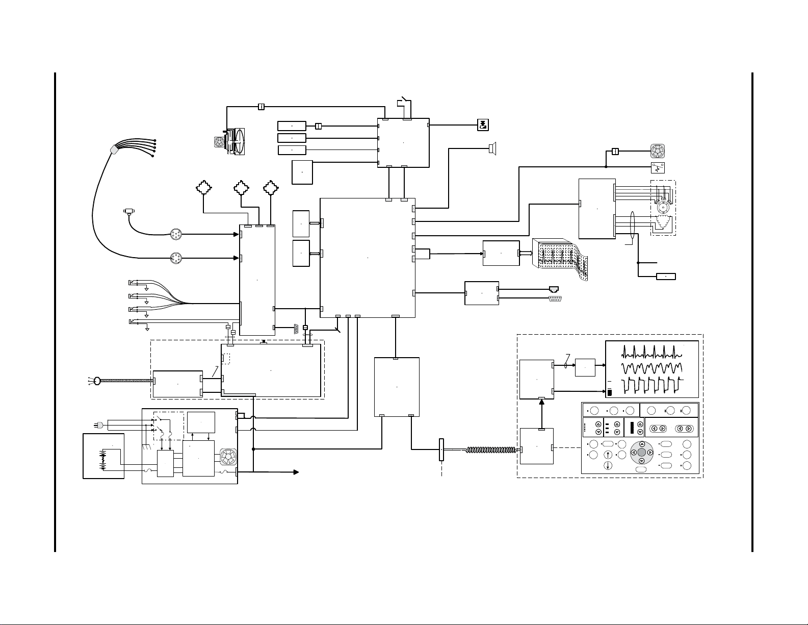
1.1 System Block Diagrams
The Block Diagrams indicate the internal organization of the instrument. They are used to
gain familiarity with the instrument and to locate malfunctioning PC boards as readily as
possible. To avoid clutter, the number of PC board interconnects is minimized. The
interconnects shown represent major or essential signal flow and clock connections.
Block Diagrams Page
System Block Diagram 1-3
Cable Block Diagram 1-4
Pneumatic Block Diagram 1-5
1 - 2 0070-10-0689 CS300™ Service Manual

Safety
Disk
RA
LA
LL
Patient
Balloon
Pres sur e
Transducer
ECG
Cathet er
Extender
Patient Inputs
Recorder
AR-42
Main Board
ECG
Pressure
9
Tel e - co m
Output
RS-23 2
Exter nal
Monitor
Inputs
ECG
Pressure
Trainer
Auto Fill tubing
Drain
tubing
FAN
Peltiercooler
&heatsink
Pelti er & f an
LVDS0,1,2,C(2 ea)
RxMAIN(2)
TxMAIN(2)
BULK-RT N(2)
BUF-RxMAI N
TxMAIN
HD0- 15
ToMotor control Bd.
S
S
Motor A
Motor B
Motor C
HALL A
HALLB
HALL C
HALL+
HALL-
FromPower Supply
DC Brushless Motor
BULK20-32VDC
Shared
RAM
68HC11
Communication
Processor
6809 Micro processor
IABP Sub-system
68020 Microprocessor
Display Sub-system
0670-00-1152 or
0670-00-0788
ECG-EXT-SEL*
ECG-EX T-IN
BP-EXT-SEL*
BP-EXT-IN
SOLND-STATE
BALLOON - E XC +, -
DRIVE-EXC+,-
DRIVE-X OUT +, -
BALLOON- XOUT +, -
0670-00-0668
1mV
5uV/V/1mmHg
1VOLT/mV
1VOLT/100mmHg
FE-TX
FE-RX
FE-CLK
TRIG- PULSE *
SOLND-STATE
BATT-VOLT
BATT-CURR
To Test
Connector
REMOTE-ON*
LED-ANODE,LED-CATH
Status-FAN-FAIL*,BATT-FLT*,BATT-LOW*,BATT-OP*
BATT-GND, BATT-CUR, BATT-VOLT
+12VRecorder, -12V,+5V Vcc, +24V Sol. Driver
Power Swit ch
ON/ OF F
DGND
BD 0-7
+24V,+ -12, +5
CHARGE L ED +, -
XXXX_SOL *
K1*, K2*, K4* Fil l
K6 , K7 ,K 8 D ri ve
K3,K5Purge
FULL*,EMPTY*,K6A
J1
J4 J5
J2J3
J6
JP5
JP19 JP18
JP16
JP22
JP21
JP17
JP1
JP3
JP20
ON/OFF
JP25
JP1
JP2
JP11
JP8
JP7
JP5
JP6
JP3
0670-00-0639
Solenoid Driver
Board
Pneumatics
(solenoids, switches
andpressuret ransducers)
Front End
Board
Displ ay Boa rd
0670-00-0640
MODEM
BOARD
JP2
JP1
JP3
JP30
SystemTimer (hours)
101.3
BULK
BULK-RET
SPKR(+)
DGND
JP1
JP3
0671-00-0004
Motor
Control
Board
JP1
JP2
0670-00-0647
RECORDER
INTERFACE
BOARD
J1
J2
20
MTR-ENABL E*, MOTO R-DRIVE
MOTO R- TACH , D IG -TA CH
+5V,12V-RCD,12VRET-RCD
AR42-TXD,AR42-RTS, AR42-RES*
AR42-RXD,AR42-CTS,A R42-SYNC
0670-00-0736
Video
Board
JP23
PUMP ASSEMBLY
COOLING FAN
CMPRS-FAN-FAIL*
24V
J7
JP2
BULK(2)
Receive r
0670-00-0786
Datase tte
(FLASH)
IAB
DriveManif old
0104-00-0018
FillManifold
0104-00-0023
Dual-Head
Compressor
2
Helium
pressure
regulator
Helium
Ta n k
To S a l i ne B ag
J2
CS*,OE*
J1
0670-00-0787
Datase tte
(FLASH)
DSS
CS*,OE*
J1
Pressure
Vaccuum
0670- 00-0 763
+5V
J2
J2
Keypad
Controller
0670-00-1145
LVDS0,1,2,C(2 ea)
+5V(2),+12V(2)
RTN(4), RATE0,
RATE1
Board-to-board
Connection
J4
Dual Re ser voi r
Press ure
Transducer
PSIG
J8
ECG-EXT-OUT
BP-EXT-OUT
ECG/Press.
Outputs
RL
C
JP9
Battery
Charge
LED
Bloo d
Detec t
Sensor
(p/o
Sol Dr v)
Backlight
Inverter
J4
0671-00-0230
Speaker
JP31
CS100 Keypad
J5
Coiledcable
Te st Connector
FromFront EndBoard
1-ECG-VAR-TEST
2-BP-TEST
3-BALLOON-PRESS-TEST
4-DRIVE-PRESS-TEST
5-PCR-PLS-TEST
6-TRIG-PLS-TEST
7-SOLND-STAT-TEST
8-GND_A
9-GND_D
ECG
AUTO
AUTO
100
76
94
112
80
II
2
20
LCD Display 640X 480
105
0160-00-0071-02 or
0160-00-0113*
ECG
PRESSURE
Pacer V/ AV
Pacer A
Internal
OPEN
MENU
1:1
1:2
1:3
MAX
OFF
IABINFLATION
Earlier Later
HELP
IABDEFLATION
LaterEarlier
AUTO
START
STANDBY
TRIGGERSOURCE IAB FREQUENCY
AUGMENTATION
SEMI
AUTO
MANUAL
ZERO
PRESSURE
ALARM
MUTE
IAB
FILL
REF
LINE
AUG
ALARM
BACK
ECG/AP
SOURCES
PUMP
OPTIONS
USER
PREFERENCES
INFLATION
INTERVAL
FREEZE
DISPLAY
PRINT
STRIP
OPERATION MODE
16
3Ring
4Tip
1,2,5,6 n/ c
RJ11 Connector
Power Supply Assembly
DC Fan
AC
Power E ntr y
Module
AC IN
Fusib le l ink
24VBattery
Input
filters
Control
Board
-Power factor
correction
-Battery charger
-Regulatedsuppl ies
PowerBoard
J100
J101
J102
J103
30A
10A
10A
0014-00-0033-05
FOS Assy
Fiber-Optic
Intfc Board
0997-00-1161
p/o J2
JP15
J3
J3
J1
J2
V-BULK, B ULK-RTN
V-B U LK
BULK-RTN
V-B UL K
BULK-RT N
TxD, RxD
Rst, Sy nc
J1
TxD,RxD
FE-CLK
p/o J2
J5
S1
BedsideBP
ZeroPB-SW
Lo-Lvl
Out
iso-zone
Fiber-Optic Sensor
p/o Sensor IAB
PurgeManifold
0104-00-0026
0161-00-0022
Bat te ry A ss y
0146-00-0047-XX ( non UTS)
0146-00-0051( UTS)
Fiber Optic Sensor
Assembly
MOTOR
COMPRESSOR
ASSEMBLY
0102-00-0001
ATM
Xducer
0331-00-0119
CS300 Block Diagram
0012- 00-1 429 o r
0012- 00-1 747*
* For use with NEC64E dis play.
CS300
™
Service Manual 0070-10-0689 1 - 3
FIGURE 1-1 System Block Diagram
Theory of Operation System Block Diagrams
1 - 4 0070-10-0689 CS300
Safety Disk /
C R M Asse mb l y
Pressure
Transducer
ECG
Pat ient I np uts
Recorder
AR-42
Main Board
ECG
Pressu re
Tele-com
Output
RS-232
Exter nal
Monitor
Inputs
ECG
Pre ssu r e
Trai ne r
FA N
Pel t i er co o l e r
&heatsink
To Motor Cont roll er Bd.
S
S
MotorA
MotorB
MotorC
HALL A
HALL B
HALL C
HALL +
HALL-
DC Br u shl ess M ot or
0670-00-1152
0670-00-0668
Power Swit ch
J1
J5J4
J2
J3
J1
JP5
JP19 JP18
JP16
JP 2 2
JP23
JP17
JP1
JP3
JP20
JP25
JP1 JP 2
JP11JP8
JP7
JP3
JP5
JP6
0670-00-0639
Solenoid D r iver
Board
Front End
Board
Display Board
0670-00-0640
MODEM
BOARD
JP2
JP1
JP3
JP 3 0
0671-00- 0004
Motor
Control
Board
JP1
JP3
0670-00-0647
RECORDER
INTERFACE
BOARD
J1
J2
0670-00-0736
JP 2 1
J7
JP2
Video
Boar d
Receiver
0670-00-0786
D a t a set t e
(FLASH)
IAB
J2
J1
0670-00-0787
Datasette
(FLASH)
DSS
J1
0670-0 0-076 3
J2
J2
Keypad
Controller
PCB
0670-00-1145
Boar d- to- b oar d
Connecti on
J4
J8
ECG/Pres.
Outputs
JP9
Batt ery
Charge
LED
Backlight
Inverter
J4
0671-00-0230
Speaker
JP31
CS100 K e y pad
0331-00-0119
J5
Coi l ed cabl e
ECG
AUTO
AUTO
100
76
94
112
80
II
2
20
LCDDisplay640 X480
105
0160- 00- 00 71- 02 o r
0160- 00- 01 13*
ECG
PRESSURE
PacerV/AV
PacerA
Internal
OPEN
MENU
1:1
1:2
1:3
MAX
OFF
IABINFLATION
Earlier Later
HELP
IABDEFLATION
LaterEarlier
AUTO START
STANDBY
TRIGGER SOURCE IAB FREQUENCY
AUGMENTATION
SEMI
AUTO
MANUAL
ZERO
PRESSURE
ALARM
MUTE
IAB
FILL
REF
LINE
AUG
ALARM
BACK
ECG/AP
SOURCES
PUMP
OPTIONS
USER
PREFERENC ES
INFLATION
INTERVAL
FREEZE
DISPLAY
PRINT
STR I P
OPERATIONMODE
Po w e r S u p p l y A ssem b l y
DCFan
AC
Pow er En t ry
Module
AC IN
Fusiblelink
24V Battery
Input
fil ters
Control
Board
-Power factor
correct ion
-Batterycharger
-Regul ated suppl ies
Pow er Bo ar d
J100
J101
J102
J1 0 3
30A
10A
10A
0014-00-0033-05
FOS Assy
Fiber-Opt ic
InterfaceBoard
p/o J2
JP15
J3
J3
J1
J2
J1
p/o J2
J5
S1
Fiber -Opti c Sensor
p/o Sensor I AB
Battery Assy
0146-00-0047-X X ( non UTS)
0146-00-0051 ( U TS)
0997- 00- 1161
Fiber Optic Sensor
Assembly
0012-00-0977
FillM anifold
0104-0 0-002 3
Purge M anifold
0104-00 -0026
DriveManifold
0104-00-0018
Saf e t y V en t
Sol en o i d K 6A
Sensor s
-Empty
-Full
0012-00-0976
Helium
Tran sduc er
Ball oon
Transducer
Dri ve
Trans duc er
0012-00-0834
0012- 00- 1062
2
/
0012- 00- 1104
6
/
6
/
6
/
8
/
0012- 00- 0767
4
/
0012- 00- 1096-0 1
0012- 00-1 097-01
10/26
/
0012-00-1061
14
/
0012- 00- 1196-01
20
/
20
/
20
/
0012-00-0784-02
0012-00-0761-02
0012-00-0874-02
2
/
0012-00-0893-02
4
/
0012- 00- 0759-0 2
4
/
Compressor
Fan
Thermal
Swi t c h
0012-00-1056
From Power Suppl y
101.3
Sys t em T i mer
(hours)
4
/
2
/
0012- 00- 14 29 or
0012- 00- 17 47*
0012- 00-142 8
0012-00-1059
Chassi s
0012- 00-1 056
0012- 00-1 060
0012- 00-1 875-02
0012-00-0766
0012- 00- 1537
part of
0012- 00- 153 9
0012- 00- 1538
0012- 00- 1765
0012- 00-105 8
0012- 00- 0745
JP2
0012- 00- 0888
0012- 00- 1536
par t of
0012- 00- 1539
par t of
0012-00-1539
* For usewi th NEC64E display.
0012-00-0746
0012-00
-0785
0012-00-1422
0012-00
-0964
(UT S)
0012-00-0886- 01 - 110V
0012-00-0886- 02 - 220V
0012-00-0886- 03 - 220V ( Chinese)
0012- 00- 1682
System Block Diagrams Theory of Operation
™
Service Manual
FIGURE 1-2 Cable Block Diagram

CS300
Helium
Gauge
0
2K
4K
Helium
Cylinder
Volume Cylinder
K5
K1
K2
Fill Solenoid
Patient I.A.B.
Helium
Solenoid
RG1
C
C
21
2
Legend: Solenoids shown in normal position ( non-activated )
Solenoid (open )
Solenoid (closed)
Relief Valve
Transducer
Regulator
C - common
1 -- normally open
2 -- normally closed
3Way
Solenoid
Pump
To Solenoid
Driver PCB
Purge
Solenoids
Empty
S2
Full
Blood Back
Sensor
2 Stage
regulator
FP1
Safety Disk
Brushless
DC Motor
Filter
Pressure
Head
Muffler
Vacuum
Head
K4
Isolation
Solenoid
Muffler
To Front End PCB
Muffler
CV2
4.5 P.S.I.
Relief
Valve
1
Hall Effect
Sensors
PRESSURE
RESERVOIR
X2
Drive
Transducer
X1
Balloon
FAN
Peltier cooler
& heatsink
Manual
Fill Port
FILL MANIFOLD
DRIVE MANIFOLD
To Motor
Control PCB
To Solenoid
Driver PCB
S1
CV1
K8
K7
Pressure
Solenoid
Vacuum
Solenoid
RG2
8 P.S.I.
Back Pressure
Regulator
9 P.S.I.
Relief Valve
K6
Vent
Solenoid
REF.
SIGNAL
TUBE
SIGNAL
LED
Transducer
VACUUM
RESERVOIR
Safety
Vent
Solenoid
K3
PURGEASSEMBLY
X4
Helium
Tank
Transducer
To Front End PCB
K6A
Muffler
™
Service Manual 0070-10-0689 1 - 5
Theory of Operation System Block Diagrams
FIGURE 1-3 Pneumatic Block Diagram

Circuit Descriptions Theory of Operation
1.2 Circuit Descriptions
1.2.1 Power Supply for CS300
P/N INPUTS OUTPUTS
0014-00-0033-05 AC Mains, Battery 18 - 32 volts (main or bulk supply)
24 V (solenoid supply) +/-12 volts, +5 volts,
Battery charger, charge LED drive
1.2.2 Sensor Module
P/N DESCRIPTION
0992-00-0202 The Fiber Optic Sensor Assembly accepts an optical signal that
communicates blood pressure information from a sensor placed in
the intra-aortic balloon.
1 - 6 0070-10-0689 CS300™ Service Manual

Theory of Operation Circuit Descriptions
Circuit Descriptions Page
Power Supply Assembly Block Diagram P/N 0014-00-0033-05 1-8
Front End Description 1-9
Front End PCB Drawing P/N 0670-00-0668 1-10
Front End PCB Block Diagram P/N 0670-00-0668 1-11
Main Board Description 1-12
Main PCB Drawing P/N 0670-00-1152 / 0670-00-0788 1-13
Main Board Block Diagram P/N 0670-00-1152 / 0670-00-0788 1-15
Display Controller Description 1-16
Display Controller PCB Drawing P/N 0670-00-0640 1-17
Display Controller Block Diagram P/N 0670-00-0640 1-18
Solenoid Driver Description 1-19
Solenoid Driver PCB Diagram P/N 0670-00-0639 1-20
Solenoid Driver PCB Block Diagram P/N 0670-00-0639 1-21
Keypad Controller Description 1-22
Keypad Controller PCB Diagram P/N 0670-00-1145 1-23
Keypad Controller Block Diagram P/N 0670-00-1145 1-24
Video Receiver Description 1-25
Video Receiver Board Diagram P/N 0670-00-0736 1-26
Video Receiver Block Diagram P/N 0670-00-0736 1-27
Sensor Module Description 1-28
Sensor Module Board Diagram P/N 0997-00-1161 1-29
Sensor Module Block Diagram P/N 0997-00-1161 1-30
CS300™ Service Manual 0070-10-0689 1 - 7

1 - 8 0070-10-0689 CS300
1
2
3
AC
ACN
GND
EMI
FILTER
DC
FAN
POWER
FACTOR
CORRECTION
CONVERTER
(PFC)
J1
1
2
3
BATT
BATT
BATT-RET
J3
4
BATT-RET
90-264
VAC
20-32 VDC
BATTERY
CHARGER
MULTIPLE
OUTPUT
FLYBACK
CONVERTER
1
2
3
4
BULK
BULK
BULK-RET
BULK-RET
1
2
3
4
BATT-VOLT
BATT-CURR
AGND
REMOTE-ON*
5
6
7
8
BATT-LOW *
BATT-HRT*
BATT-FLT*
BATT-OP*
P/O J100
J103
J101 J102
INPUT PCBA
POWER PCBA
STATUS CONNECTOR
POWER
CONNECTORS
CONTROL
PCBA
SELV
BARRIER
SELV
BARRIER
CHASSIS
GROUND
PFC
CONTROL
ISO
CONVERTER
CONTROL
CHARGER CONTROL
FAN DRIVE
STATUS LINES
FLYBACK
CONVERTER
CONTROL
INTERNAL BULK
MAINS
ON/OFF
MAINS
FUSES
BATTERY
FUSE
BULK
FUSE
EMI
FILTER
BULK
SWITCH
RECTIFIER
BRIDGE
HOUSEKEEPING
SUPPLY
CONTROL
LOGIC
1
2
3
4
+12V
12RET
-12V
5RET
5
6
7
8
+5RET
+24V
24RET
+5V
1
2
3
4
+12V
12RET
-12V
5RET
5
6
7
8
+5RET
+24V
24RET
+5V
9
10
11
12
FF_SD_DISABLE
REDUCED_AIR
13
14
15
LED-CATH
DGND
LED-ANODE
P/O J100
18-32 VDC
POWER ENTRY MODULE
MAINS
ISOLATION
CONVERTER
NOT USED
NOT USED
Service Manual
™
FIGURE 1-4 Power Supply Assembly Block Diagram
P/N 0014-00-0033-05
Circuit Descriptions Theory of Operation

Theory of Operation Circuit Descriptions
Front End Description
ECG Pressure
• Patient isolation • Patient isolation
• ESU filters • Pressure scaling
• Lead selection • Auto zero circuit
• Reference lead drive • Pressure gain adjustment
• External ECG signal selection • External pressure signal selection
• Pacer detection • Pressure ESD protection
• ECG trigger signal conditioning
• ECG size
• ECG ESD protection
• ECG defibrillator protection
Data Acquisition Microcontroller
• Pneumatic transducer amplifiers • Serial interface to Main Board
• A/D converter for display signals • ECG circuit control latches
• 12-Bit A/D converter • Pressure circuit control latches
• Transducer excitation voltages • Controls A/D conversion
• Pacer blanking
• ESU detect and time-out
• Auto zero control
CS300™ Service Manual 0070-10-0689 1 - 9

1 - 10 0070-10-0689 CS300
Circuit Descriptions Theory of Operation
FIGURE 1-5 Front End PCB Drawing
P/N 0670-00-0668
™
Service Manual

CS300
CSD
Circuitry
Amp
ESU Flt
Lead Sel
Lead Drv
Diff Amp
Mod
De-Mod
De-Mod
Amp
&
Lead
Fault
Var Ga in
DAC
Pacer Det
&
ESU Det
Mux
A/D
Conv
68HC711
Micro-
controller
Gain Adj
&
Zero Ofst
He tank-Pres
ECG-Trig
BP-Trig
ECG-Disp
BP-Disp
Drive-Pres
Bal-Pres
Atmos-Pres
2.5V Ref
Batt-Volt
Batt-Cur
Tem p
A-Gnd
Pwr
Conv
Iso Pwr
Supply
Iso-Barrier
BP-Trig
BP-Disp
ECG-Trig
ECG-Disp
BP
ECG
To Comm Proc.
on Main Board
Ext BP In
Ext ECG In
Trigg er
Processing
Pressure
ECG
Patient
Inputs
5uV/V/1mmHg
1mV
Mod
Display
Gain
Balloon-Exc(+)
Balloon-Exc(-)
Balloon-Xout(+)
Balloon-Xout(-)
Drive-Exc(+)
Drive-Exc(-)
Drive-Xout(+)
Drive-Xout(-)
J4
J5
Excit.
Voltage
Reg.
2.5VRef
+5V -5V
+5V Ref
Scaling
Amp
On board
transducer
Offset
Atmospheric Pressure Channel
Instrumentation Amp
Offset
Balloon Pressure Channel
Instrumentation Amp
Offset
Drive Pressure Channel
2.5V
Reg.
Independent
Reference
Buffer
Buffer
4mV / mmHg
4mV / mmHg
Balloon-Press
Tes t ( to P6)
Drive-PressTes t ( to P6)
Tan k -E x c
Tan k -S i g
Tan k -G n d
Buffer
+5V Ref.
Scaling
Amp
Helium Tank
Pressure Channel
Tem p
Sensor
Solnd-state
Trig-pulse*
Batt-volt
Batt-curr
FE-TX
FE-RX
FE-Clk
Scaling
Amp
BattCurr
BattVolt
Buffer
Buffer
Solnd-Stat-Test (To P6)
Trig-Pls-Test (To P6)
Buffers
68HC711
Micro-Controller
125mV/V
250mV/A
Temperature
Channel
12 MHz
Xtal
Divide-
by-48
Clk-62.5 KHz
3.00 MHz
ESU-Present*
Pacer-Blanking*
LD-Flt-Detect
Trai ner*
Slew-rate-exceeded
HW-ESU-exceeded
Xducer*
60Hz / 50Hz*
ECG-Ext-Sel*
BP-Ext-Sel*
1 Volt / mV
1 Volt / 100mmHg
External Monitor Inputs
ECG-Ext-In
ECG-Ext-Sel*
BP-Ext-In
BP-Ext-Sel*
ECG-Ext-Out
BP-Ext-Out
Solnd-State
50/60 HZ
Notch
60 Hz / 50 Hz*
J3
Trainer
ECG
Pressure
6 - Trig-Pls-Test
7 - Solnd-Stat-Test
8 - Gnd_A
9 - Gnd_D
1 - ECG-Var-Test
2 - BP-Test
3 - Balloon-Press-Test
4 - Drive-Press-Test
5 - Pcr-Pls-Test
Diagnostic Output
P6
Service Manual 0070-10-0689 1 - 11
™
FIGURE 1-6 Front End PCB Block Diagram
P/N 0670-00-0668
Theory of Operation Circuit Descriptions

Circuit Descriptions Theory of Operation
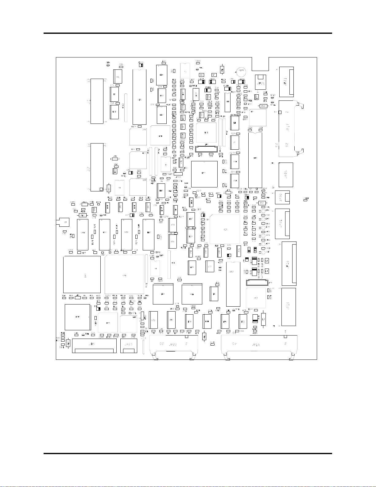
Main Board Description
6809 Microprocessor (2 MHz) 68020 Microprocessor (33 MHz)
• 50 k EPROM (Datasette) • 2 M EPROM (Datasette)
• 12 k RAM • 2 M RAM
• Solenoid control signals • Real time clock and NVRAM
• Watchdog timer • Display interface
• Alarm processing • Recorder control
• Pneumatic switch status • Recorder interface
• IABP control status • RS-232 interface
• Motor speed D/A converter • Modem interface
• Configuration DIP switch
68HC711 Microprocessor
Serial interface to the Front End, Solenoid Driver and Keypad Controller boards
• Shared RAM interface
Shared RAM
• Port 1 interfaces with the 68020 sub-system
• Port 2 interfaces with the 6809 sub-system
• Port 3 interfaces with the 68HC711 (communications processor)
1 - 12 0070-10-0689 CS300™ Service Manual
Theory of Operation Circuit Descriptions
FIGURE 1-7 Main PCB Drawing
P/N 0670-00-1152
CS300™ Service Manual 0070-10-0689 1 - 13

Circuit Descriptions Theory of Operation
FIGURE 1-8 Main PCB Drawing
P/N 0670-00-0788
1 - 14 0070-10-0689 CS300™ Service Manual

CS300
68020 (DSS)
Processor
Circuit
Group
6809 (IAB)
Processor
Circuit
Group
68HC11
(Comm)
Processor
Circuit
Group
RAM
Datasette
VIA
D/A Conv
Audio
Synth
& Amp
Shared
RAM
RAM
Datasette
QUAD
UART
To Modem
To Thermal Printer
& RS232
spare
To D is p l a y
Controller
To F r o n t
End
To K ey p ad
Control
To Solenoid
Driver
To Motor
Control
To Speaker
RTC /
NVRAM
JP5
p/o JP16
p/oJP17JP21JP20JP22JP31p/oJP1
6
JP19
+5V
+12V
-12
+24
From
Power
Supply
JP18
To
Power
Supply
Status
Remote On
p/o JP17
From
Solenoid
Driver
Status
™
Service Manual 0070-10-0689 1 - 15
Theory of Operation Circuit Descriptions
FIGURE 1-9 Main Board Block Diagram
P/N 0670-00-1152 / 0670-00-0788

Circuit Descriptions Theory of Operation
Display Controller Description
• Generates system display via Hitachi ACRTC device
• Acts as peripheral to 68020 (DSS) processor
• Transmits video data and control signals to display head via LVDS transmitter
• Provides serial communications link between Comm Proc and Keypad Controller
• Provides V-Bulk supply voltage to Display Head assembly with soft-start circuit
1 - 16 0070-10-0689 CS300™ Service Manual

CS300
™
Service Manual 0070-10-0689 1 - 17
Theory of Operation Circuit Descriptions
FIGURE 1-10 Display Controller PCB Drawing
P/N 0670-00-0640

1 - 18 0070-10-0689 CS300
XILINX
FPGA
Clock
Gen
Frame
Buffer
Hitachi
Graphics
Processor
Osc
Bidir
Buff
Data
CS,WE
DTACK
MAD
ADDR
DATA
LD,UD
FLM,LP
DISP-OFF
7.5M HZ
3.75MHZ
(Frame Buffer
&
LCD
Controller)
30MHz
Config.
PROMs
CS,CLK
LVDS
Driver
30MHz
VS,MRD
DRW,AS
CS,WS(2)
Data
CP
JP1
JP2
JP3
SoftStart
Ckt
KCTxD
KCRxD
Diff
DrvRcv
IRQ
To M ai n Board
To D i spl ay Head
V-Bulk,
Rtn
CP-EN
OE*
T/R*
Circuit Descriptions Theory of Operation
™
Service Manual
FIGURE 1-11 Display Controller Block Diagram
P/N 0670-00-0640

Theory of Operation Circuit Descriptions
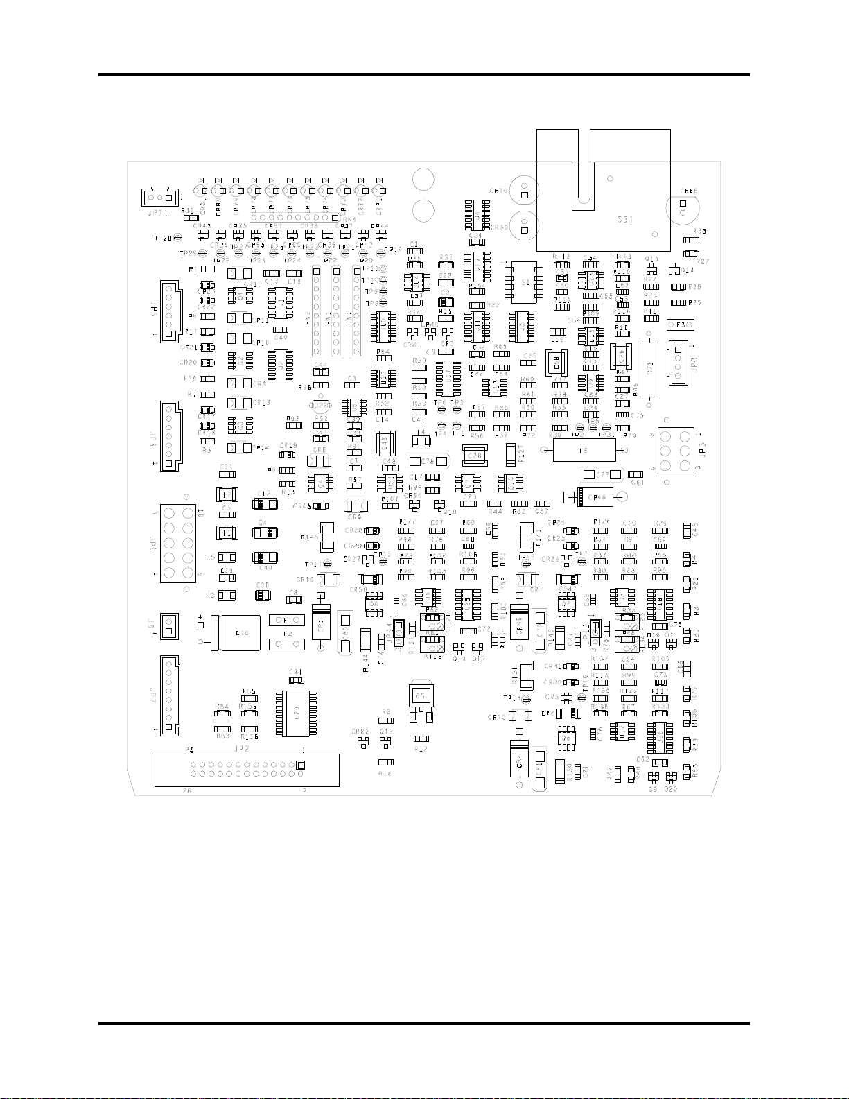
Solenoid Driver Description
• Receives solenoid control signals (11) from Main Board
• Energizes fill solenoids (K1, K2, K3, K4 and K5)
• Energizes drive solenoids (K6, K6A, K7 and K8)
• Provides prolonged inflation watch-dog timer
• De-energizes drive solenoids if watch-dog timer expires and sends signal to Main Board
• Energizes Peltier devices in Safety Disk
• Incorporates blood detection circuitry
CS300™ Service Manual 0070-10-0689 1 - 19
Circuit Descriptions Theory of Operation
FIGURE 1-12 Solenoid Driver PCB Diagram
P/N 0670-00-0639
1 - 20 0070-10-0689 CS300™ Service Manual

MAIN BOARD
JP2
JP7
BD0 - 8
6809 DATA BUS
SWITCH
STATUS
FET CONTROL
FILL
SOLENOIDS
DRIVE
SOLENOIDS
FET CONTROL
(K1,K2,K4)
(K6,K7,K8)
PROLONGED
INFLATION
FAIL SAFE
LED
INDICATORS
WDOG*
RD_SOL_STATE*
JP5
JP3
FILL
SOLENOIDS
DRIVE
SOLENOIDS
SOL_WATCHDOG*
K7*, K8*
XXXX_SOL*
SOL_WDOG*
JP9
CHRG-LED-, +
CHRG-LED -, +
K1*,K2*,K4*
K6*,K7*,K8*
PELT_ON/OFF*
SOL_WDOG*
JP11
JP1
ON/OFF
DGND
POWER
SWITCH
ON/OFF
+5v-PELT
+24v,+12v,+5V-12V
JP6
PURGE
SOLENOIDS
PURGE
SOLENOIDS
FET CONTROL
(K3 , K5)
FULL*
EMPTY*
K6A*
DRAIN TUBING
240HZ
LED
DRIVE
BB_LED+, -
CLOCK
TUBE_SGN
REF_SGN
DEMOD
DEMOD*
SYNCHRONOUS
DETECTOR
LOW PASS
FILTER
LOW PASS
FILTER
COMPARATOR
SENSOR
BLOCK
REF_SIGNAL
TUBE_SIGNAL
2.5V
REFERENCE
2.5V
+12VF
PELT_ON/OFF*
AMBIENT
TEMP.
PELTIER
CONTROL
JP8
CONDENSATE
REMOVAL
MODULE
PELT_CONTROL
PELT-PWR
+12VP (FAN)
SAFETY VENT
SOLENOID
VOLUME
CYLINDER
SENSORS
LED
CHARGE
INDICATOR
MAIN BOARD
K3*,K5*
BBALARM*
CS300
Service Manual 0070-10-0689 1 - 21
™
FIGURE 1-13 Solenoid Driver PCB Block Diagram
P/N 0670-00-0639
Theory of Operation Circuit Descriptions

Circuit Descriptions Theory of Operation
Keypad Controller Description
• 68HC11 micro-controller continually scans key matrix of 7 Rows X 6 Columns (42 keys
max)
• Micro-controller controls LEDs via serial input LED driver chip
• Micro-controller communicates switch closures and receives LED data via serial
communications link to Comm Processor on Main Board
• Passes video interface (LVDS) through to Video Receiver PCBA
• Provides DC/DC converters from V-Bulk to +5V and +12V to power this PCBA, Video
Receiver and LCD display panel
1 - 22 0070-10-0689 CS300™ Service Manual
 Loading...