

Page 1
Compressor Mini
Service Manual
CRITICAL CARE
Page 2

Compressor Mini Service Manual
Notes
2 Revision 02
Page 3

Compressor Mini Service Manual
Contents
1. Important ............................................................................................................................. 4
2. Introduction ......................................................................................................................... 8
2.1 General description...................................................................................................... 8
2.2 Main units..................................................................................................................... 8
2.3 Functional principles .................................................................................................... 9
3. Description of functions ....................................................................................................10
3.1 Compressed air production ....................................................................................... 10
3.2 Compressor cooling .................................................................................................. 12
3.3 Electric functions .......................................................................................................12
4. Disassembling and assembling ......................................................................................... 16
4.1 General ....................................................................................................................... 16
4.2 Handling PC boards .................................................................................................. 16
4.3 Tools ..........................................................................................................................16
4.4 Compressor cover ..................................................................................................... 17
4.5 Internal tubing ............................................................................................................ 17
4.6 Compressor with motor ............................................................................................. 18
4.7 Compressor maintenance ......................................................................................... 19
4.8 Water separator .........................................................................................................20
4.9 Thermoelectric cooler ................................................................................................ 21
4.10 Axial fan ..................................................................................................................... 22
4.11 Radial fan ...................................................................................................................22
4.12 Standby valve ............................................................................................................ 23
4.13 Drainage valve ........................................................................................................... 23
4.14 PC board ....................................................................................................................24
5. Service procedures ........................................................................................................... 25
5.1 Transport safety lock .................................................................................................25
5.2 Replacing / resetting fuses ........................................................................................26
5.3 Setting the DIP switch ...............................................................................................27
6. Troubleshooting ................................................................................................................. 28
7. Preventive maintenance .................................................................................................... 31
7.1 General ....................................................................................................................... 31
7.2 5.000 hour overhaul ...................................................................................................31
7.3 10.000 hour overhaul .................................................................................................33
8. Index ..................................................................................................................................34
9. Diagrams............................................................................................................................ 36
9.2 Wiring diagram ........................................................................................................... 36
9.2 Functional block diagram ..........................................................................................37
Revision 02 3
Page 4
Compressor Mini Service Manual
1. Important
1
General
• This Service Manual is intended to give service
personnel sufficient knowledge about the
Compressor Mini to be able to diagnose any
possible problem or failure and to identify which
part or component that causes the problem or
failure. The description is limited to a level, which
allows the service personnel to track problems
down to parts that are found in the spare part list.
• This Service Manual is also intended to give
information how to perform preventive
maintenance.
• Documentation for Compressor Mini consists of:
– Compressor Mini – User's Manual
– Compressor Mini – Service Manual
– Compressor Mini – Installation Instructions
– Compressor Mini, Alternative connections –
Installation Instructions
• The Compressor Mini – User's Manual is an
indispensable complements to the Service
Manual for proper servicing.
Text inside a box is used to highlight important
information.
• In addition to the Important information given
here and in the related documents, always pay
attention to applicable local and national
regulations.
• Responsibility for the safe functioning of the
equipment reverts to the owner or user in all
cases in which service or repair has been done
by a non-professional or by persons who are not
employed by or authorized by MAQUET, and
when the equipment is used for other than its
intended purpose.
• Data on internal pressures are given in Pa (psi).
Airway pressures are given in cm H
1 hPa = 1 mbar 1 mbar = 1 hPa
1 kPa = 10 mbar 1 mbar = 0.1 kPa
1 kPa = 0.01 bar 1 bar = 100 kPa
1 kPa ≈ 10 cm H
≈ 0.01 at 1 at ≈ 100 kPa
1 kPa
1 kPa
≈ 0.01 kgf/cm
1 kPa
≈ 0.01 kp/cm
≈ 0.145 psi 1 psi ≈ 6.9 kPa
1 kPa
O 1 cm H
2
2
2
1 kgf/cm
1 kp/cm
O (Pa).
2
O ≈ 0.1 kPa
2
2
≈ 100 kPa
2
≈ 100 kPa
Symbols used in this manual
• ESD sensitive components. When
handling ESD-sensitive devices,
established procedures must be
observed to prevent damage.
• Technical training. Refers to the
Technical training supplied by
MAQUET.
• Service contract. Refers to the
Service contract supplied by
MAQUET.
• Special waste. Discard disposable,
replaced and left-over parts in
accordance with appropriate
industrial and environmental
standards.
Abbreviations used in this manual
If not stated otherwise:
• The 115 V AC / 60 Hz version is referred to as the
115 V version.
• The 220 V AC / 50 Hz – 240 V AC / 50 Hz version
is referred to as the 230 V version.
Software versions
• There are three different software versions
released for the Compressor Mini:
– SW version V1.1.0
– SW version V1.2.0
– SW version V2.1
The information in this Service Manual is valid for
all SW versions unless otherwise stated. The SW
version list above is valid as from October 2004.
For further information regarding the SW
versions, refer to chapter 3. 'Description of
functions' section 28. 'PC board'.
Installation
• Only personnel trained and
authorized by MAQUET shall be
permitted to install the Compressor
Mini. The installation and handingover procedures are described in the
Compressor Mini – Installation Instructions.
4 Revision 02
Page 5
Compressor Mini Service Manual
1. Important
Functional check
• After any installation, maintenance or service
intervention in the Compressor Mini, perform a
'Function check'. Refer to the User's Manual.
Hazard notices
• Before disassembling or assembling the
Compressor Mini, make sure that the:
– Power switch is set to Off.
– Mains power cable is disconnected.
– Gas supply is disconnected.
– The system is cleaned according to instructions
in the Compressor Mini – User's Manual,
chapter 'Cleaning'.
• With mains power supply connected to
the Compressor Mini, there are
energized electrical components as
well as moving mechanical parts inside
the equipment. All personnel must
exercise extreme caution when in the
vicinity of this equipment if fault tracing
or adjustments are performed with
mains power supply connected and
with the compressor cover removed.
• The Compressor Mini generates compressed air
at a pressure of 450 kPa (64 psi). Do not attempt
to connect or disconnect the compressed air line
or service the compressor section while
compressed air is being supplied. Do not direct
the compressed air line toward the eyes or
directly onto unprotected skin surfaces.
To the responsible service personnel
• The contents of this document are not binding.
If any significant difference is found between the
product and this document, please contact
MAQUET for further information.
• We reserve the right to modify products without
amending this document or advising the user.
• Only personnel trained and authorized
by MAQUET shall be permitted to
perform installation, service or maintenance. Only MAQUET genuine spare
parts must be used. PC boards (spare
parts) must always be kept in a package for
sensitive electronic devices. MAQUET will not
otherwise assume responsibility for the materials
used, the work performed or any possible
consequences of same.
• The device complies to standards and
requirements as stated in the 'Compressor Mini –
User's Manual'.
Service
• The Compressor Mini must be
serviced at regular intervals by
personnel trained and authorized by
MAQUET. Any maintenance or service
must be noted in a log book.
• It is recommended that maintenance
and service is done as a part of a
service contract with MAQUET.
• Preventive maintenance must be performed at
regular intervals as follows:
– At 5.000 hours of operation as described in this
Service Manual, chapter 'Preventive
maintenance'.
– At 10.000 hours of operation as described in
this Service Manual, chapter 'Preventive
maintenance'.
• When working with ESD sensitive
components, always use a grounded
wrist band and a grounded work
surface. Adequate service tools must
always be used.
• The Compressor Mini is oil free, and
oil must not be used when servicing
the compressor.
• Discard all disposable, replaced and
left-over parts in accordance with
appropriate industrial and
environmental standards.
1
Revision 02 5
Page 6
Compressor Mini Service Manual
1. Important
1
Environmental declaration
Purpose
This environmental declaration is for a
Compressor Mini unit.
Number codes within brackets refers to the
position number on each component in the
Functional Block Diagram in chapter Diagrams.
Components with special environmental
concern
Components listed below shall be disposed of in
accordance with appropriate industrial and
environmental standards.
Printed circuit boards
• Control board (28)
Other electronics
• Compressor with motor (2)
• Thermoelectric cooler with Peltier element (4)
• Standby valve (9)
• Drainage valve (12)
• Radial fan (16)
• Axial fan (18)
• Mains power inlet with fuses and
On/Off switch (20-22)
• Mains power terminal (23)
• Transformer (24)
• Rectifier (25)
• DC Capacitor (26)
• Autofuse (27)
• Motor relay (29)
• Radial fan capacitor (30)
• Motor capacitor (31)
• Thermostat (32)
• Buzzer (33)
• Internal cabling
Construction materials
The construction materials used in Compressor
Mini in % of the total weight.
Metal – total 43%
• Aluminum
• Steel
• Stainless steel
• Brass
• Copper
• Bronze
• Zinc (surface treatment)
• Chromium (surface treatment)
• Nickel (surface treatment)
Polymeric material – total 13%
• ABS (Acrylonitrile-butadiene-styrene plastic)
• PA (Polyamide)
• PE (Polyethylene)
• PET (Polyethylene terephtalate)
• PMMA (Polymethyl methacrylate)
• POM (Polyoxymethylene)
• PTFE (Polytetrafluoroethylene)
• PUR (Polyurethane)
• PVC (Polyvinyl chloride)
• CR (Chloroprene Rubber)
• EPDM (Ethylene Propylenendienmonomer)
• FPM (Fluoro Rubber)
• IR (Isoprene Rubber, Synthetic)
• NBR (Nitrile rubber)
• VMQ (Silicone)
Electronics – total 44%
• Printed circuit boards, cables etc.
Others – very small amounts
• Threadlocking adhesives
• Tape
• Corrugated cardboard
• Label
• Marking ink
6 Revision 02
Page 7
Compressor Mini Service Manual
1. Important
Articles of consumption
1. Compressor dust filter
2. Thermoelectric coolers dust filter
3. Air inlet filter
4. Water separator filter incl. O-ring
5. Compressor shock absorbers
6. Compressor maintenance kit incl:
– Cylinder liners
– Piston rings
– Valve plates
– Gaskets
– O-rings
– Misc. screws.
Items 1 – 4: Changed approx. every 5.000 hours.
Items 5 – 6: Changed approx. every 10.000 hours.
1
Power consumption
550 W at nominal voltage.
Noise level
Approximately 50 dB(A) at a distance of 1 m.
Packing materials
•Plywood
• Steel
• PE (Polyethyelene)
• PA (Polyamide)
• Corrugated cardboard
• Desiccator
Revision 02 7
Page 8
Compressor Mini Service Manual
2. Introduction
2.1 General description
The Compressor Mini is designed to supply medicalgrade compressed air. The compressor has a
capacity of approx. 30 l/min at a pressure of 350 –
450 kPa (50 – 64 psi).
The Compressor Mini can be placed on the ventilator
cart to form a compact unit which is easy to move.
It can also be used as a stand-alone unit.
2
The Compressor Mini is well insulated against noise
and therefore does not cause disturbance when used
during operations.
The Compressor Mini is equipped with a standby
function. In the standby mode, the compressor will
start to deliver compressed air if the hospital central
gas supply fails.
The Compressor Mini is fitted with temperature and
pressure alarms. The temperature alarm is activated
if the compressor should overheat or if there is a
malfunction in the thermoelectric cooler.
The pressure alarm is activated if the air pressure in
the compressed air tank is too high or too low.
The Compressor Mini is available in two different
versions; 115 V/60 Hz and 230 V/50Hz. With the
exception of air connections and ratings of various
electrical components, these versions are identical.
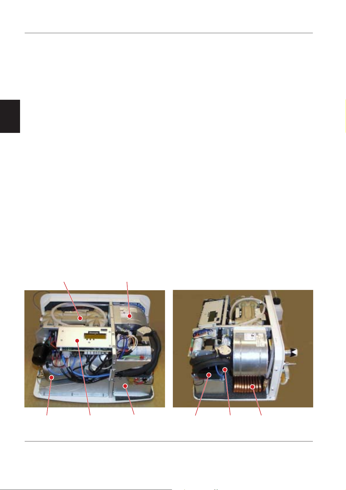
2.2 Main units
The Compressor Mini comprises the following main
units:
• Compressor with motor
• Cooling coil
• Water separator
• Thermoelectric cooler including axial fan
• Tank
• Radial fan for compressor cooling
• PC board including display.
Compressor
with motor
Tank
PC board
including display
Radial fan for
compressor cooling
Thermoelectric
cooler
Thermoelectric
cooler
Water
separator
Cooling
coil
8 Revision 02
Page 9

Compressor Mini Service Manual
2.3 Functional principles
This description refers to the Functional block
diagram, see chapter 9. 'Diagrams'.
Compressed air production
The dry and clean compressed air is produced as
follows:
• Ambient air from the inside of the Compressor Mini
is supplied to the Compressor with motor via the
Air inlet with filter.
• The action of the compressor imparts heat to the
compressed air. To provide preliminary cooling, the
air flow is passed through the Cooling coil before it
enters the Thermoelectric cooler. The cooling coil
is cooled by the air stream forced through the unit
by the Radial fan.
• In the Thermoelectric cooler, the air temperature is
further lowered. Moisture that remains in the
compressed air is then partly transformed into
water by condensation. This water is separated
from the air in the Water separator and routed to
the Drainage bottle via the Drainage valve.
• A Pressure regulator is connected to the
compressed air tubing. Air pressure in excess of
the preset level on this pressure regulator, normally
approx. 450 kPa (64 psi), will cause a flow which is
fed back to the inlet of the compressor.
• The dried, compressed air is collected in the Tank
and routed to the Compressed air outlet. The Tank
is equipped with a Safety valve. If water, for some
reason, is collected in the Tank, this water can be
removed by manually pressing the Drain valve pin.
• Compressed air from the hospital central gas
supply can be connected to the Compressed air
inlet and the Compressor Mini can then be started
in stand-by mode. The air pressure in the
Compressed air inlet is monitored by a pressure
sensor in Compressor Mini. If the hospital central
gas supply fails, the compressor automatically
starts to deliver compressed air. The Standby valve
will switch between the Compressed air inlet and
the Tank as compressed air source.
Compressor cooling
Efficient cooling is required to keep the specified
working temperature inside the unit, but also to
condensate water from the compressed air.
• The Compressor with motor is cooled by the air
stream forced through the unit by the Radial fan
and the two fans in the compressor. The cooling air
is cleaned by a Dust filter mounted on the rear
panel.
• The Thermoelectric cooler is cooled by the air
stream forced through its Cooling flanges by the
Axial fan. The cooling air is cleaned by a Dust filter
mounted on the underside of Compressor Mini.
Electric functions
Mains power to the compressor is connected via and
controlled by the On/Off switch which also includes
mains fuses. A number of electric power supply
functions (transformer, rectifier, capacitors, etc.) are
mounted inside the unit. Internal mains power supply
is distributed from the Mains power terminal.
Electrical control functions, the display and the
indicator LEDs are located on the PC board.
Three Temperature sensors and two pressure
sensors monitor the unit. The Buzzer (audible alarm)
and the red alarm indicator LED is activated during
temperature alarm and/or pressure alarm. The alarm
will be silenced if the Compressor Mini is switched off.
Transport safety lock
The Transport safety lock, mounted into the rear
panel, secures the Compressor with motor to the
rear panel. This will relieve the load from the shock
absorbers.
The Transport safety lock must be removed before
starting the Compressor Mini.
2
Revision 02 9
Page 10
Compressor Mini Service Manual
3. Description of functions
The text in this chapter refers to the Circuit and
connection diagrams and the Functional block
diagram, see chapter 9. 'Diagrams'.
The number in each sub-heading refers to the
position number on each component in the
Functional block diagram.
3.1 Compressed air production
1. Air inlet with filter
The Air inlet with filter supplies ambient air from the
inside of the unit to the Compressor with motor.
The filter is made of a felt, and must be replaced at
3
the 5.000 hour overhaul as well as at the 10.000 hour
overhaul. The filter must not be cleaned in any liquid.
2. Compressor with motor
The Compressor Mini is equipped with an integrated
compressor and electric motor unit.
The electric motor is a single phase motor supplied
with mains power. There are two different versions of
the motor, one for 115 V and one for 230 V.
The motor is fitted with a self-resetting thermal
switch that will cut the power supply to the motor
if the temperature at the switch exceeds approx.
130°C (266°F). When the motor cools down, the
thermal switch will automatically restart the motor.
As motors fitted with a self-resetting termal
switch can restart automatically, all personnel
must exercise extreme caution when in the
vicinity of this equipment if fault tracing is
performed with mains power supply connected
and with the compressor cover opened or
removed.
The compressor is an oil free twin-cylinder assembly
in which the filtered air is compressed by the action
of the twin pistons. A manifold pipe is connected
between the two cylinder heads so that the
compressed air generated collectively by both
pistons is available at a single outlet on one of the
cylinder heads.
The compressor’s capacity is at least a flow rate of
30 l/min at a pressure of 350 kPa (50 psi).
An overhaul of the compressor must be performed at
the 10.000 hour overhaul.
3. Cooling coil
A preliminary cooling of the compressed air is
provided by the Cooling coil assembly, which is
made of metal tubing. The compressed air to this
cooling coil is supplied from the compressor and the
output is connected to the Thermoelectric cooler.
The Cooling coil is cooled by the air stream forced
through the unit by the Radial fan. This air stream is
then routed to the Compressor with motor.
4. Thermoelectric cooler
The Compressor Mini is equipped with a Thermoelectric cooler. The thermoelectric cooler is a selfcontained unit including a 12 V Peltier element which
has one cool side and one warm side.
The compressed air is supplied to the cool side of
the Peltier element. When the temperature of the
compressed air is lowered, moisture that remains in
the air is partly transformed into water by
condensation. This water is then collected in the
Water separator connected to the outlet of the
Thermoelectric cooler.
The temperature at the Peltier element is controlled
by the PC board. The temperature sensor TS3,
connected to the Peltier element monitors the
temperature at the cool side of the element. To avoid
formation of ice in the thermoelectric cooler, power
supply to the Peltier element will be cut if the
temperature drops below a specified limit.
The warm side of the Peltier element is equipped
with Cooling flanges and is cooled by the air stream
provided by the Axial fan. A thermostat mounted at
the cooling flanges will cut the power to the Peltier
element if the warm side is overheated, refer to
section 32. 'Thermostat' below.
5. Water separator
The Water separator is a standard compressed air
filter (5 microns) provided to filter the air as well as to
separate water from the air. This water separator is
connected to the outlet of the Thermoelectric cooler,
and it supplies compressed air to the Tank (via a
one-way valve).
Water separated from the air is collected in the metal
bowl. The water separator is automatically drained at
regular intervals by the Drainage valve, and the water
is collected in the Drainage bottle.
The Water separator must be overhauled at the
5.000 hour overhaul as well as at the 10.000 hour
overhaul.
10 Revision 02
Page 11

Compressor Mini Service Manual
6. Pressure regulator
The compressed air supply is tapped off at the Water
separator and applied to the Pressure regulator. This
device is actually a pressure relief valve.
Pressure in excess of the set level, normally approx.
450 kPa (64 psi), opens this relief valve. The excess
compressed air flow is returned to the inlet of the
compressor. This arrangement effectively silences
the outlet of this relief valve.
7. Tank
The compressed air Tank is a metal container with a
volume of approx. 1.25 liters. A Safety valve and a
manual Drain valve is connected to the Tank.
8. Safety valve
A spring-loaded Safety valve is connected to the
Tank. The valve will open if the pressure inside the
tank exceeds approx. 700 kPa (102 psi).
9. Standby valve
The Standby valve is powered with 6 V and
electrically controlled by the PC board. The standby
pressure levels differ between the SW versions.
The Standby valve is a three-port valve with the
following function:
1. If the air pressure in the hospital central gas
supply, connected to the Compressed air inlet,
is above approx.:
• 300 kPa (44 psi) for SW version V1.1.0
• 250 kPa (36 psi) for SW version V1.2.0 and V2.1
the Standby valve connects this inlet with the
Compressed air outlet. The compressor is in
standby mode.
2. If the air pressure in the hospital central gas
supply, connected to the Compressed air inlet,
drops and stays below approx.:
• 300 kPa (44 psi) for SW version V1.1.0
• 250 kPa (36 psi) for SW version V1.2.0 and V2.1
for more than 2 seconds, the compressor starts
to supply compressed air to the Tank. At the
same time, the Standby valve will switch to
connect the Tank with the Compressed air outlet.
The compressor runs in active mode.
3. If the air pressure in the hospital central gas
supply, connected to the Compressed air inlet,
rises and stays above approx.:
• 350 kPa (50 psi) for SW version V1.1.0
• 300 kPa (44 psi) for SW version V1.2.0 and V2.1
for more than 30 seconds, the compressor stops.
At the same time, the Standby valve will switch
to connect the Compressed air inlet with the
Compressed air outlet. The compressor returns
to standby mode.
10. Compressed air inlet
Compressor Mini is equipped with a Compressed air
inlet. The purpose of this air inlet is to provide
compressed air from the hospital central gas supply
via Compressor Mini when used as a standby unit.
The inlet nipple can be adapted to local standards.
The inlet air connection nipple is provided with a
M12 x 1 thread.
The standby function is further described in section
9. 'Standby valve' above and in the User's Manual.
11. Compressed air outlet
The Compressed air outlet is connected to the Tank
via the Standby valve. The outlet nipple can be
adapted to local standards. The outlet air connection
nipple is provided with a M12 x 1 thread.
A test nozzle, provided as a service tool, can be used
when performing functional checks or troubleshooting on the Compressor Mini. It provides a
simulated load that permits rapid, easy checks of the
output pressure.
When testing the Compressor Mini, the test nozzle
should be connected to this outlet so that
compressed air flows through the nozzle. Output
pressure can then be read on the display.
The test nozzle permits an air flow of approx. 30 l/min
at 350 kPa (50 psi). An air pressure of 350 – 400 kPa
(50 – 58 psi) indicated on the display shows that the
compressor is operating correctly.
12. Drainage valve
The Drainage valve is powered with 12 V and
electrically controlled by the PC board.
The purpose of the Drainage valve is to remove
water collected in the Water separator at regular
intervals.
The valve is closed in non-activated condition.
During operation, the valve will be activated (open)
for approx. 0.5 seconds twice every minute by the
timing circuit on the PC board.
When the valve opens, the water collected in the
water separator will be transported to the Drainage
bottle.
13. Drainage bottle
The Drainage bottle collects the water that is
extracted from the compressed air by the Water
separator. It is a plastic container with a screw cap
into which the water hose from the water separator is
connected. There are ventilation holes in the cap.
3
Revision 02 11
Page 12

Compressor Mini Service Manual
14. Drain valve
The manual Drain valve is connected to the bottom
of the Tank with a plastic tube. This valve is a springloaded valve that is provided to drain the tank if
water, for some reason, collects in the tank. The
valve pin must be pushed manually.
The Drain valve can also be used to decrease the
internal air pressure e.g. during Function check or
during troubleshooting of the unit.
3.2 Compressor cooling
15. Dust filter – compressor
This Dust filter, made of a synthetic material, is
mounted on the rear panel of the unit. The purpose
3
of this filter is to clean the cooling air forced through
the unit by the Radial fan and the two fans in the
compressor.
The filter must be inspected and cleaned regularly as
described in the User's Manual, chapter 'Cleaning'.
The filter must be replaced at the 5.000 hour
overhaul as well as at the 10.000 hour overhaul.
16. Radial fan
The Compressor Mini is equipped with a Radial fan.
The fan is supplied with mains power as long as the
29. 'Motor relay' is activated. There are two different
versions of the fan, one for 115 V and one for 230 V.
The purpose of this Radial fan is to provide forced air
cooling for the Cooling coil and for the Compressor
with motor.
The forced cooling air stream provided by the Radial
fan enters the unit via the 15. 'Dust filter' and exits
via the outlet on the underside of the unit.
17. Dust filter – thermoelectric cooler
This Dust filter, made of a synthetic material, is
mounted on the underside of the unit. The purpose
of this filter is to clean the cooling air forced through
the Cooling flanges of the Thermoelectric cooler.
The filter must be inspected and cleaned regularly as
described in the User's Manual, chapter 'Cleaning'.
The filter must be replaced at the 5.000 hour
overhaul as well as at the 10.000 hour overhaul.
18. Axial fan
The Compressor Mini is equipped with an Axial fan.
The fan is supplied with 12 V power supplied by the
PC board.
The purpose of this Axial fan is to provide forced air
cooling for the 19. 'Cooling flanges' of the
Thermoelectric cooler.
The forced cooling air stream provided by the Axial
fan enters the unit via the 17. 'Dust filter' and exits
via the outlet on the underside of the unit.
19. Cooling flanges
The warm side of the Peltier element in the Thermoelectric cooler is equipped with Cooling flanges.
The purpose of these Cooling flanges is to lower the
temperature in the Thermoelectric cooler and thus
make the cooler work more efficient.
3.3 Electric functions
20. Mains power inlet
The mains power cable is connected to the Mains
power inlet, a male connector mounted on the rear
panel of the unit.
The Mains power inlet, the holder for the Mains fuses
F3/F4 and the On/Off switch is one complete unit.
On the 115 V-version, the mains power cable must
have a hospital grade plug.
21. Mains fuses F3/F4
There are two mains power fuses, F3 and F4.
The value for the mains fuses is as follows:
• 115 V version .....................................8.0 AT, 250 V
• 230 V version .....................................4.0 AT, 250 V
22. On/Off switch
The On/Off switch is the circuit breaker between the
mains power fuses F3/F4 and the power supply to
the rest of the unit.
23. Mains power terminal
Mains power from the On/Off switch is connected to
the Mains power terminal and, from this terminal,
distributed to the rest of the unit.
12 Revision 02
Page 13

Compressor Mini Service Manual
24. Transformer
The transformer used is a toroid transformer. The
same transformer is used in the 115 V and 230 V
versions, but the electrical connection of the
transformer differs.
The transformer is fitted with a non-resetting thermal
switch that will disconnect the current through the
transformer if it is overheated.
25. Rectifier
The Rectifier is supplied with 12 V AC from the
transformer. The output from the rectifier, approx.
15 V DC, is supplied to the PC board via the
Autofuse F2. The rectifier consists of a rectifier
bridge assembled as a complete, exchangable unit.
26. DC capacitor
The DC capacitor is a rectifer smoothing capacitor.
27. Autofuse F2
The Autofuse F2, rated 20 A, is connected to the
rectifier output to protect the units DC circuit.
A button on the autofuse is used to reconnect the
fuse if it blows.
28. PC board
The PC board controls most of the electric functions
within the Compressor Mini. The PC board is protected by the 800 mAT fuse F1 connected to the board.
Note: Operating time and pressure calibration
factors are stored on the PC board. These data will
be lost when replacing the PC board.
There are two different versions of the PC board.
The PC boards versions can be identified by the
design of the cover plate, refer to illustrations below:
• Version B. To be used with SW version V2.1.
When delivered as spare part, the SW is always
stored on the PC board.
The main functions of the PC board are:
3
Microprocessor
The PC board functions are controlled by a
microprocessor. The microprocessor also contains
memories e.g. for the software, for the operating
time meter and for pressure calibration factors.
There are three different software versions released
for Compressor Mini:
• SW version V1.1.0 intended for PC board of
Version A.
• SW version V1.2.0 intended for field update of PC
board of Version A. The update is performed with a
software download tool.
• SW version V2.1 intended for PC board of Version B.
The main difference between the SW versions are the
standby pressure levels. Refer to section 9. 'Standby
valve' in this chapter.
The SW version list above is valid as from October
2004.
Display
The Display is the user interface of the unit. It shows
e. g. operating mode, operating time, outlet air
pressure and alarm messages. Refer to the User's
Manual.
During startup, the SW version number is shown in
the display.
Indicator LEDs
There are three Indicator LEDs:
• On/Off (green)
• Version A. Replaced in production and as spare
part by Version B due to obsolete components.
To be used with SW versions V1.1.0 and V1.2.0.
Revision 02 13
• Standby (yellow)
• Alarm (red)
The indicator LED functions are described in the
User's Manual.
Page 14

Compressor Mini Service Manual
DIP switch
The DIP switch is a selector with 6 different switches.
It is used to:
• Select air pressure unit shown on the display.
• Select language shown on the display.
• Activate service mode.
The different DIP switch settings are described in
chapter 5. 'Service procedures'.
Voltage regulation and distribution
The different DC voltage levels used in Compressor
Mini are regulated and distributed from the PC
board.
The distributed voltage levels are:
3
• +12 V. Used by the termoelectric cooler, the axial
fan and the drainage valve.
• +6 V. Used by the motor relay and the standby
valve.
• +5 V. Used internally on the PC board.
Test points are described below.
Pressure monitoring
There are two pressure sensors mounted on the PC
board, PS1 and PS2:
• PS1 is connected to the tank and measures the
pressure inside the tank.
• PS2 is connected to the standby valve and
measures the pressure in the compressed air inlet.
The pressure sensors are connected to their
pressure sourses with tubes.
Low pressure alarm or High pressure alarm is activated if measured pressures are outside alarm limits.
Alarm conditions are described in the User's Manual,
chapter 'Technical data'.
Measured max. pressure value is stored in the
memory and can be displayed in the Service mode.
Temperature monitoring
There are three temperature sensors mounted inside
Compressor Mini:
• TS1 is mounted at the cooling air inlet on the rear
panel. It measures the temperature of the ambient
air.
• TS2 is mounted in the compressor compartment.
It measures the temperature at the compressor.
• TS3 is mounted inside the thermoelectric cooler.
It measures the temperature at the Peltier element.
The temperature sensors are connected to the PC
board with cables.
Temperature alarms are activated if measured
temperatures are outside alarm limits. Alarm
conditions are described in the User's Manual,
chapter 'Technical data'.
Measured max. and min. temperature values are
stored in the memory and can be displayed in the
Service mode.
Cooling control
The cooling control can be divided in two parts;
cooling of the compressed air and cooling of the
compressor.
Cooling of the compressed air: The temperature at
the Peltier element inside the thermoelectric cooler is
controlled by the PC board. Input data for this
control is supplied by the temperature sensors TS1
and TS3. The PC board also controls the axial fan
that provides forced cooling of the cooling flanges.
Cooling of the compressor: Cooling of the
compressor is monitored by the PC board. Input
data is supplied by the temperature sensor TS2.
Standby control
Compressed air from the hospital central gas supply
connected to the compressed air inlet is monitored
by pressure sensor PS2. As long as the pressure in
the hospital central gas supply is within specified
limits, Compressor Mini will remain in standby mode.
If the pressure drops below specified limit, the PC
board will activate the motor relay and the
compressor will start to produce compressed air.
If the pressure in the hospital central gas supply
returns, Compressor Mini will return to standby
mode.
If the internal pressure is above 200 kPa (29 psi) at
startup, a 'quick-start' will be performed. Software
version is not shown on the display, and the pixel
and buzzer tests are excluded.
Conditions for the standby function are described in
section 9. 'Standby valve' above and in the User's
Manual.
14 Revision 02
Page 15

Compressor Mini Service Manual
Water drainage control
The drainage valve is controlled by the PC board.
To ensure a gentle startup, the drainage valve will be
kept open a few seconds during the compressor
startup.
During operation, the drainage valve will be opened
for 0.5 seconds twice a minute. This is to remove
water collected in the water separator and transport
this water to the drainage bottle.
To ensure a gentle stop of the compressor, the
drainage valve will be kept open a few seconds when
the compressor is turned off.
Test points
For troubleshooting purpose, the PC board is
equipped with a number of test points. The values
stated below are referred to ground. Ground points
(GND1–GND4) are available on the PC board.
• TP1 = Unregulated power supply, +11 to +16 V DC.
• TP2 = +6 V DC for power supply to motor relay
and standby valve.
• TP3 = Unregulated power supply, +11 to +16 V DC
fused by F1.
• TP4 = Vcc_5 V; +5,5 V DC for power supply to PC
board circuits.
• TP5 = Vcc; +5 V DC for PC board backup power.
• TP6 = Vcc+12 V; +12 V DC for power supply to
pressure transducer amplifiers.
• TP7 = 3.7–5.7 V DC constant power supply for
display backlight.
• TP8 = Pressure sensor PS1 signal.
• TP9 = Pressure sensor PS2 signal.
• TP10 = +12 V DC for power supply to axial fan and
drainage valve.
32. Thermostat
The Thermostat is mounted in the compartment of
the axial fan and the cooling flanges. If the temperature at the thermostat exceeds approx. 70°C
(158°F), the thermostat will cut the power supply to
the Peltier element. The power supply will be
reconnected when the temperature drops below
approx. 55°C (131°F)
33. Buzzer
The Buzzer will be activated during alarms. The
buzzer is controlled by the PC board.
At power failure or when the unit is switched off,
the buzzer will be activated during 12 seconds.
3
34. Transport safety lock
The Transport safety lock is mounted into the rear
panel. The purpose of the transport safety lock is to
secure and stabilize the Compressor with motor e.g.
during transport of the unit. This will relieve the load
on the motor mountings (shock absorbers).
Remove the transport safety lock before starting the
unit. Keep the transport safety lock parked on the
drainage bottle holder when not in use.
29. Motor relay
Power supply to the Compressor with motor and to
the Radial fan is distributed via the Motor relay.
The relay is supplied with a 6 V control signal by the
PC board.
30. Radial fan capacitor
Start capacitor for the radial fan motor.
31. Motor capacitor
Start capacitor for the compressor motor.
Revision 02 15
Page 16

Compressor Mini Service Manual
4
Before the compressor cover is removed, make
sure that the mains power supply is disconnected
and that the compressed air tank is
depressurized.
With mains power supply connected to
the Compressor Mini, there are
energized electrical components as
well as moving mechanical parts inside
the equipment. All personnel must
exercise extreme caution when in the
vicinity of this equipment if fault tracing
or adjustments are performed with
mains power supply connected and
with the compressor cover removed.
After any service intervention in the Compressor
Mini, perform a 'Function check' according to
instructions in the User's Manual.
4. Disassembling and
assembling
4.1 General
• Only personnel trained and authorized
by MAQUET shall be permitted to
perform installation, service or
maintenance of the Compressor Mini.
• All service associated with the Compressor Mini,
including disassembly and assembly, is to be done
in accordance with this Service Manual.
• This chapter describes the disassembling and
assembling required to replace spare parts and to
perform preventive maintenance.
• If not stated otherwise, the assembling procedure
is the reverse of the described disassembling
procedure.
• To avoid the possible spillage of water, before
disassembling the Compressor Mini, run the unit
until the drainage valve operates to drain water into
the drainage bottle. Then remove the drainage
bottle, empty the bottle and refit it.
• Wait for the Compressor Mini to cool down before
proceeding.
• Locking compound is used on many of the screw
connections. Further information can be found
below in this chapter. Old locking compound must
be removed and the threads must be cleaned
before any new compound is applied.
4.2 Handling PC boards
• The PC board contains components that
are highly sensitive to static electricity.
Those who come into contact with circuit
boards containing sensitive components
must take certain precautions to avoid
damaging the components (ESD protection).
• When working with ESD sensitive components
always use a grounded wristband and grounded
work surface. Adequate service tools must also be
used.
• PC boards (spare or exchange parts) must always
be kept in protective packaging for sensitive
electronic devices.
• PC boards must not be inserted or removed while
power is applied to the PC boards.
• Remove and insert the PC boards very carefully to
avoid damage to the connectors.
4.3 Tools
• Standard service tools.
16 Revision 02
Page 17

Compressor Mini Service Manual
4.4 Compressor cover
Disassembling
Before the compressor cover is removed, make
sure that the mains power supply is disconnected
and that the compressed air tank is depressurized.
• Remove the four screws (1).
• Pull out and lift off the cover (2).
H
6
Assembling
The assembling procedure is the reverse of the
disassembling procedure as described above.
4
4.5 Internal tubing
The couplings used for the internal tubing (nylon
tubes) are quick-action couplings. These couplings
are used for compressed air tubes as well as for
drain water tubes.
The tubes must be cut at a right angle and the ends
of the tubes must be without burrs.
To disconnect a tube
• Push in and hold the ring (1).
• Pull out the tube (2).
To connect a tube
• Push the tube (2) into the coupling. Push the tube
forcefully toward the stop inside the coupling.
• Pull the tube to make sure that it is secured to the
coupling.
Revision 02 17
Page 18

Compressor Mini Service Manual
4.6 Compressor with motor
Disassembling
6
H
• Remove the cover as described in section
4.4 'Compressor cover'.
• Remove the six screws (1) holding the cover plate.
• Lift off the cover plate (2).
6
6
4
9
<
;
• Disconnect the two tubes (3 and 4).
• Disconnect the motor cable connector (5).
• Remove the four screws (6).
=
=
18 Revision 02
Page 19

Compressor Mini Service Manual
?
?
?
@
• Lift out the compressor with motor.
Note: The sound absorbing mat attached to the
chassis may cause the mounting rails (7) to stick.
Use a large screwdriver (8) to pry them loose.
• Remove the mounting rails (7) from the compressor.
• Remove the shock absorbers (9) from the mounting
rails.
4
Assembling
The assembling procedure is the reverse of the
disassembling procedure as described above.
Locking compound (Loctite 243) must be used at:
• Screws holding the shock absorbers to the
mounting rails.
A
• Screws holding the shock absorbers to the
compressor with motor.
• Screws holding the mounting rails to the base
plate.
4.7 Compressor maintenance
The only spare parts available for the compressor
with motor are included in the 'Maintenance kit,
10.000 hour'.
Detailed instructions for the compressor
maintenance are enclosed in the maintenance kit.
Revision 02 19
Page 20

Compressor Mini Service Manual
4.8 Water separator
Disassembling
6
• Remove the cover as described in section
4.4 'Compressor cover'.
• To remove the complete water separator:
– Remove the three screws (1).
– Disconnect all tubings from the water separator
and lift off the water separator (2).
H
9
4
9
;
• To replace the filter in the water separator:
– Disconnect the tube (3).
– Unscrew the water separator housing (4).
– The water separator filter (5) can now be replaced.
Assembling
The assembling procedure is the reverse of the
disassembling procedure as described above.
Note: Loctite 243 must be used on the screws (1).
<
20 Revision 02
Page 21

Compressor Mini Service Manual
4.9 Thermoelectric cooler
Disassembling
• Remove the cover as described in section
4.4 'Compressor cover'.
• Disconnect the two cables at the terminal (1).
H
=
9
• Disconnect the connector P6 (2) at the PC board.
• Remove the four screws (3) and carefully pull out
the thermoelectric cooler (4).
• Disconnect the tubings at the cooler inlet (5) and
the cooler outlet (6).
• Lift off the thermoelectric cooler (4).
6
Assembling
The assembling procedure is the reverse of the
<
disassembling procedure as described above.
4
;
;
9
Revision 02 21
Page 22

Compressor Mini Service Manual
4.10 Axial fan
Disassembling
• Remove the thermoelectric cooler as described in
section 4.9 'Thermoelectric cooler'.
• Disconnect the connector P2 (1) at the PC board.
6
H
• The cable is routed through a rubber bushing in the
housing. Remove the rubber bushing from the
housing and carefully pull the cable connector
through the bushing.
• Remove the four screws (2) holding the axial fan.
• Lift off the axial fan (3).
9
Assembling
The assembling procedure is the reverse of the
H
4
disassembling procedure as described above.
Make sure that the direction of the air stream created
by the fan is correct. The air must be drawn via the
fan towards the cooling flanges. Refer to the
'Functioning block diagram'.
H
6
H
9
4.11 Radial fan
Disassembling
• Remove the cover as described in section
4.4 'Compressor cover'.
• Disconnect the cable connector (1).
• Remove the four screws (2) holding the radial fan.
• Carefully pull out and lift off the radial fan (3).
Assembling
The assembling procedure is the reverse of the
disassembling procedure as described above.
22 Revision 02
Page 23

Compressor Mini Service Manual
4.12 Standby valve
Disassembling
• Remove the radial fan as described in section
6
H
4.11 'Radial fan'.
• Remove the inlet and outlet air connection nipples
(1 and 2).
• Disconnect tubings and cable connectors from the
standby valve (3).
• Lift off the standby valve (3).
Assembling
The assembling procedure is the reverse of the
disassembling procedure as described above.
Note: The port marked 2 on the standby valve must
be mounted towards the aluminum block.
Sealing compound (Loctite 542) must be used on
the air connection nipple threads.
4
9
6
9
H
4.13 Drainage valve
Disassembling
• Remove the cover as described in section
4.4 'Compressor cover'.
• Disconnect the connector P3 (1) at the PC board.
• Remove the two screws (2) holding the drainage
valve (3).
• Disconnect all tubings from the drainage valve.
• Lift off the drainage valve.
Assembling
The assembling procedure is the reverse of the
disassembling procedure as described above.
Revision 02 23
Page 24

Compressor Mini Service Manual
4.14 PC board
Disassembling
• Remove the cover as described in section
4.4 'Compressor cover'.
• Disconnect all tubings and cable connectors from
the PC board.
• Loosen the screw (1) a few turns.
• Remove the two screws (2).
• Lift off the PC board assembly (3).
6
Assembling
The assembling procedure is the reverse of the
disassembling procedure as described above.
Spare part PC boards are delivered with the
following settings:
4
9
H
• Factory calibrated pressure transducers.
• Time meter set to 0.
• kPa set as pressure unit.
• English set as language.
For pressure unit and language setting, refer to
chapter 5. 'Service procedures', section 'Setting the
DIP switch'.
When delivered as spare part, the SW is always
stored on the PC board.
24 Revision 02
Page 25

Compressor Mini Service Manual
5. Service procedures
Before the compressor cover is removed, make
sure that the mains power supply is disconnected and that the compressed air tank is
depressurized.
With mains power supply connected to
the unit, there are energized electrical
components as well as moving
mechanical parts inside the equipment.
All personnel must exercise extreme
caution when in the vicinity of this
equipment if fault tracing or adjustments are performed with mains power
supply connected and with the
compressor cover removed.
After any service intervention in the Compressor
Mini, perform a 'Function check' according to
instructions in the User's Manual.
6
5
5.1 Transport safety lock
The Transport safety lock is mounted into the rear
panel. The purpose of the transport safety lock is to
secure and stabilize the compressor with motor e.g.
during transport of the unit.
Remove the transport safety lock before starting the
unit. Keep the transport safety lock parked on the
drainage bottle holder when not in use.
To remove the transport safety lock
• Unscrew the transport safety lock (1) and pull it
out.
• Park the transport safety lock on the drainage
bottle holder.
Do not discard the transport safety lock. It must be
used during transport of the unit.
To refit the transport safety lock
The procedure for refitting the transport safety lock is
the reverse of the removing procedure previously
described.
Revision 02 25
Page 26

Compressor Mini Service Manual
5.2 Replacing / resetting fuses
Mains fuses F3/F4
There are two mains power fuses, F3 and F4, located
at the mains power inlet.
The value for the mains fuses is as follows:
• 115 V version ................................... 8.0 AT, 250 V
H
• 230 V version ................................... 4.0 AT, 250 V
6
To replace the fuses:
• Pull out the connector at the mains power inlet.
• Pull out the fuse holder (1).
• Replace the mains fuses (2).
Autofuse F2 20 A
The Autofuse F2, rated 20 A, protects the units DC
circuit.
5
9
;
To reset the fuse:
• Remove the cover as described in section
4.4 'Compressor cover'.
• Push the button (3) on the autofuse.
PC board fuse F1
The fuse F1, rated 800 mAT, protects the PC board.
To replace the fuse:
• Remove the cover as described in section
4.4 'Compressor cover'.
• Replace the fuse (4).
26 Revision 02
Page 27

Compressor Mini Service Manual
5.3 Setting the DIP switch
The following settings are made with the DIP
switch (1) on the PC board:
• Reset, SW1. Used for factory calibration of the
6
SW1 SW2 SW3 SW4 SW5 SW6
ON–––––N/A
(Reset)
OFF ON OFF – – – Psi
OFF OFF ON – – – kPa
OFF ON ON – – – Bar
OFF – – ON OFF OFF Italian
OFF – – OFF ON OFF Swedish
OFF – – ON ON OFF German
OFF – – OFF OFF ON Not used
OFF – – ON OFF ON Spanish
OFF – – OFF ON ON French
OFF – – ON ON ON English
OFF OFF OFF OFF OFF OFF Service
mode
PC board. Not intended for field service. Must
remain in OFF-position.
• Pressure unit, SW2 – SW3. To select the pressure
unit shown on the display.
• Language, SW4 – SW6. To select the language
shown on the display.
• Service mode, SW1 – SW6. To show highest
stored pressure reading and lowest/highest stored
temperature reading. The service mode loop is
shown in the flow chart below.
Note: Make sure to set the appropriate pressure
unit and language after using the service mode.
The adjacent DIP switch-illustration shows the
following pressure unit and language settings:
– kPa (SW 2–3)
– English (SW 4–6).
Setting procedure
• Make sure that the Compressor Mini is switched
Off.
• Remove the cover as described in section 4.4
'Compressor cover'.
• Set SW2 – SW6 to select appropriate pressure unit
and language (or service mode).
• Start the Compressor Mini with the On/Off switch.
Check that the selected settings are activated.
• Mount the cover as described in section 4.4
'Compressor cover'.
5
Service mode startup display.
1 second.
Highest pressure value stored (bar).
INT (Internal) = PS1
EXT (External) = PS2.
5 seconds.
Lowest temperature value stored (°C).
A (Ambient) = TS1
D (Thermoelectric cooler) = TS3
M (Motor) = TS2.
5 seconds.
Highest temperature value stored (°C).
A (Ambient) = TS1
D (Thermoelectric cooler) = TS3
M (Motor) = TS2.
5 seconds.
Revision 02 27
Page 28

Compressor Mini Service Manual
6. Troubleshooting
Before you start any troubleshooting, begin if
possible by questioning the person reporting the
fault. Ask how the fault appeared.
Make sure that there has been no operating error.
For this purpose, see also the chapter
'Troubleshooting' in the User's Manual.
There should be a logical trend to your troubleshooting. First try to trace the faulty function. Then
the most suitable procedure is to track down the
exact fault by systematically replacing individual
spare parts, one at a time.
One purpose of the 'Description of functions' and the
'Diagrams' in this Service Manual is to make it easier
to trace faults.
Malfunction Action
The compressor will not start; the green On/Off-LED
does not come on:
6
The compressor runs, but the mains power LED
does not come on:
Before the compressor cover is removed, make
sure that the mains power supply is disconnected
and that the compressed air tank is
depressurized.
With mains power supply connected to
the unit, there are energized electrical
components as well as moving
mechanical parts inside the equipment.
All personnel must exercise extreme
caution when in the vicinity of this
equipment if fault tracing or adjustments are performed with mains power
supply connected and with the
compressor cover removed.
After any service intervention in the Compressor
Mini, perform a 'Function check' according to
instructions in the User's Manual.
• Check the mains power supply.
• Check fuses (F1, F2, F3 and F4).
• Check all electrical cables and connectors. Tighten
loose connectors.
• Check voltage at the 26. DC Capacitor:
– If the voltage is 11 – 16 V: Malfunction on the
PC board.
– If the voltage is 0 V: Malfunction in the
transformer or rectifier.
• Replace the PC board.
No compressed air is delivered although the
compressor is running:
The compressor stops; the mains power LED stays
on:
28 Revision 02
• If the pressure shown on the display is normal,
check the compressed air outlet for obstruction or
damage and replace it if necessary.
• If the pressure shown on the display is too low,
check the internal compressed air tubing for
leakage. Clear obstructions, tighten loose
connectors.
• Check the drainage valve and the standby valve.
Replace if necessary.
• Check the operation of the compressor. Overhaul
or replace if necessary.
• Mains power below specified range.
• Check the internal wiring and connectors.
• The thermal switch inside the motor may have
tripped. The thermal switch will reset automatically
and the motor will restart.
Page 29

Compressor Mini Service Manual
Malfunction Action
Operating pressure (shown on the display) is correct
during functional check but drops when a ventilator
is connected:
The 'Low pressure alarm' is activated:
• Too high air consumption. The compressor cannot
supply the equipment connected.
• The dust filters or the air inlet filter are clogged.
Clean or replace the filters if necessary.
• Check the internal compressed air tubing for
leakage. Clear obstructions, tighten loose
connectors.
• Check the operation of the compressor with motor.
Overhaul or replace if necessary.
• Too high air consumption. The compressor cannot
supply the equipment connected.
• Check the internal compressed air tubing for
leakage. Clear obstructions, tighten loose
connectors.
• The dust filters or the air inlet filter are clogged.
Clean or replace the filters if necessary.
• Pressure alarm malfunction. Replace the PC board.
• Check the operation of the compressor with motor.
Overhaul or replace if necessary.
• Malfunction in the pressure regulator.
The 'High pressure alarm' is activated:
The 'Temperature alarm 1' is activated: • Ambient air temperature is too high.
• Pressure alarm malfunction. Replace the PC board.
• Malfunction in the pressure regulator.
• The compressor’s ventilation holes are blocked.
Check cooling air inlet on the rear panel as well as
cooling air outlet on the underside of the unit.
• The compressor's dust filter is clogged.
Clean or replace if necessary.
• Check the operation of the radial fan.
Replace if necessary.
• Temperature alarm malfunction.
Replace the PC board.
• Malfunction in TS2 (temperature sensor 2).
6
Revision 02 29
Page 30

Compressor Mini Service Manual
Malfunction Action
The 'Temperature alarm 2' or 'Temperature alarm 3'
is activated:
Abnormal amounts of water flush out through the
drain valve when the valve pin is depressed:
• Ambient air temperature is too high.
• The thermoelectric cooler's ventilation holes are
blocked. Check cooling air inlet as well as cooling
air outlet on the underside of the unit.
• The thermoelectric cooler's dust filter is clogged.
Clean or replace if necessary.
• Check the operation of the axial fan.
Replace if necessary.
• Thermoelectric cooler malfunction.
Replace the thermoelectric cooler.
• Temperature control malfunction.
Replace the PC board.
• Temperature alarm malfunction.
Replace the PC board.
• Malfunction in TS1 (temperature sensor 1).
• Check the internal water tubing.
• Check the operation of water separator and the
drainage valve. Overhaul or replace if necessary.
• Malfunction in the thermoelectric cooler.
Replace if necessary.
• Malfunction on the PC board. Replace if necessary.
The display does not indicate the correct operating
pressure:
6
Water appears to be leaking from the Compressor
Mini:
Water does not accumulate in the drainage bottle at
regular intervals. Drainage is too frequent, not
frequent enough, or does not occur at all:
• Check the internal compressed air tubing for
leakage. Clear obstructions, tighten loose
connectors.
• Check the operation of the compressor with motor.
Overhaul or replace if necessary.
• Malfunction on the PC board. Replace if necessary.
• Check the drainage bottle for leaks or a loose
connection. Replace the bottle if necessary.
• Check all water tubes and connectors. Tighten
loose connectors.
• Check the water separator. Replace if necessary.
• Check the drainage valve. Replace if necessary.
• Check all water tubes and connectors. Clear
obstructions and/or replace faulty components.
• Check the water separator. Replace if necessary.
• Check the drainage valve. Replace if necessary.
• Malfunction on the PC board. Replace if necessary.
30 Revision 02
Page 31

Compressor Mini Service Manual
7. Preventive maintenance
Before the compressor cover is removed, make
sure that the mains power supply is disconnected
and that the compressed air tank is depressurized.
With mains power supply connected to
the unit, there are energized electrical
components as well as moving
mechanical parts inside the equipment.
All personnel must exercise extreme
caution when in the vicinity of this
equipment if fault tracing or adjustments are performed with mains power
supply connected and with the
compressor cover removed.
Any service or maintenance must be noted in a
log book.
7.1 General
The Compressor Mini must be serviced at regular
intervals by personnel trained and authorized by
MAQUET. Any maintenance or service must be
noted in a log book.
It is recommended that maintenance and service is
done as a part of a service contract with MAQUET.
Preventive maintenance must be performed as
follows:
• 5.000 hour overhaul when replacing filters.
• 10.000 hour overhaul when replacing filters, shock
absorbers and overhauling the compressor.
All disposable parts must be discarded
according to local regulations and in an
environmentally acceptable way.
After any service intervention in the Compressor
Mini, perform a 'Function check' according to
instructions in the User's Manual.
Preparations
• Make sure that the Compressor Mini is properly
cleaned before performing any maintenance. For
cleaning procedures, refer to the User's Manual.
• Make sure that the Compressor Mini works
properly before performing any maintenance.
Tools
• Standard service tools.
7.2 5.000 hour overhaul
When performing the maintenance, a 'Maintenance
kit, 5.000 hour' should be used.
For disassembling and assembling instructions, refer
to chapter 4. 'Disassembling and assembling'.
• Replace the compressors dust filter (1).
7
6
Revision 02 31
Page 32

Compressor Mini Service Manual
• Replace the thermoelectric coolers dust filter (2).
H
• Replace the air inlet filter (3).
9
7
;
<
• Replace the O-ring (4).
• Replace the water separator filter (5).
Safety inspection
• Make a visual inspection of the Compressor Mini
for external defects or damages. Replace defective
or damaged parts.
• Check the mains power cable and the mains power
inlet for damage.
• Perform a leakage current test. The leakage current
test is a standard procedure regulated by IEC 60
601-1 or corresponding national standards.
Allowable values and test methods are defined in
the standard. The use of a leakage tester, e. g.
Bender Safety Tester 601/751 or equivalent is
recommended.
Completing the 5.000 hour overhaul
• Connect the test nozzle, provided as a service tool,
to check the output pressure. An air pressure of
350 – 400 kPa (50 – 58 psi) indicated on the display
shows that the compressor is operating correctly.
• Perform a 'Function check'. Refer to the User's
Manual.
• Note in the units log book that a 5.000 hour
overhaul has been performed.
32 Revision 02
Page 33

Compressor Mini Service Manual
7.3 10.000 hour overhaul
When performing the maintenance, a 'Maintenance
kit, 10.000 hour' should be used.
For disassembling and assembling instructions, refer
to chapter 4. 'Disassembling and assembling'.
• Replace the following parts as described in section
7.2 5.000 hour overhaul:
– The compressors dust filter.
– The thermoelectric coolers dust filter.
– The air inlet filter.
– The water separator filter.
• Replace the compressors shock absorbers (1).
6
• Perform an overhaul of the compressor.
Detailed instructions are enclosed in the
compressor maintenance kit.
Safety inspection
• Make a visual inspection of the Compressor Mini
for external defects or damages. Replace defective
or damaged parts.
• Check the mains power cable and the mains power
inlet for damage.
• Perform a leakage current test. The leakage current
test is a standard procedure regulated by IEC 60
601-1 or corresponding national standards.
Allowable values and test methods are defined in
the standard. The use of a leakage tester, e. g.
Bender Safety Tester 601/751 or equivalent is
recommended.
Completing the 10.000 hour overhaul
• Connect the test nozzle, provided as a service tool,
to check the output pressure. An air pressure of
350 – 400 kPa (50 – 58 psi) indicated on the display
shows that the compressor is operating correctly.
• Perform a 'Function check'. Refer to the User's
Manual.
• Note in the units log book that a 10.000 hour
overhaul has been performed.
7
Revision 02 33
Page 34

Compressor Mini Service Manual
8. Index
Introduction
Description of functions
Disassembling and assembling
Service procedures
5.000 hour overhaul 31
10.000 hour overhaul 33
A
Air inlet 9 10
Air inlet filter 32
Axial fan 8,9 12 22
B
Buzzer 9 15
C
Compressed air inlet 9 11
Compressed air outlet 9 11
Compressor cover 17
Compressor maintenance 19 33
Compressor with motor 8,9 10 18
Cooling coil 8,9 10
Cooling flanges 9 12
D
DC capacitor 13
DIP switch 14 27
Display 9 13
Drain valve 9 12
Drainage bottle 9 11
Drainage valve 9 11 23
Dust filter – compressor 9 12 31
Dust filter – thermoelectric cooler 9 12 32
F
Fuse F1 (PC board) 13 26
Fuse F2 (autofuse) 13 26
Fuse F3 (mains) 12 26
Fuse F4 (mains) 12 26
Preventive maintenance
O
On/Off switch 9 12
P
PC board 8,9 13 24
Pressure regulator 9 11
Pressure unit selection 27
R
Radial fan 8,9 12 22
Radial fan capacitor 15
Rectifier 13
S
Safety inspection 32
Safety valve 9 11
Service mode 27
Shock absorbers 19 33
Software reset 27
Software (SW) versions 13
Standby valve 11 23
T
Tank 8,9 11
Temperature sensors 9
Thermoelecrtic cooler 8,9 10 21
Thermostat 15
Tools 16
Transformer 13
Transport safety lock 9 15 25
W
Water separator 8,9 10 20
Water separator filter 20 32
Introduction
Description of functions
Disassembling and assembling
Service procedures
Preventive maintenance
H
Handling PC boards 16
I
Internal tubing 17
8
L
Language selection 27
M
Mains power inlet 12
Mains power terminal 9 12
Microprocessor 13
Motor capacitor 15
Motor relay 15
34 Revision 02
Page 35

Compressor Mini Service Manual
Notes
Revision 02 35
8
Page 36

3
5
3
5
er
0
C
5.
9
p
r
al
er
0
C
5.
er
ofuse
A
use
A
U
OG
GN
U
U
OG
U
G
9
36 Revision 02
20. Mains power inlet
21. Mains fuses F3/F4
22. On/Off switch
L
N
GND
20. Mains power inlet
21. Mains fuses F3/F4
22. On/Off switch
L
N
GND
In this manual,
the DIN IEC
757-standard
is used when
describing
lead colours;
BK = Black
BN = Brown
RD = Red
OG = Orange
YE = Yellow
GN = Green
BU = Blue
VT = Violet
GY = Grey
WH = White
PK = Pink
GD = Gold
SR = Silver
TQ = Turquoise
230 V
115 V
BK
BU
GNYE
BK
BU
GNYE
BU
BU
30. Radial fan
BN
31. Motor
capacitor
23. Mains powe
termin
23. Mains
terminal
capacitor
GNYE
PK
GNYE
BU
BN
GNYE
BU
2. Compressor
with motor
ower
B
B
BN
PK
BU
GNYE
16. Radial fan
BN
BK
BK
2
. Motor
relay
9. Standby
4. Thermoelectric cooler
Peltier element
24. Transform
Thermo 11
24. Transform
Thermo 11
valve
32. Thermostat
18. Axial fan
B
27. Autof
F2 20
N
B
27. Aut
F2 20
RD
2
Rectifi
2
Rectifier
Temperature sensors
12. Drainage
valve
RD
BK
TS2
TS3
TS1
33.
Buzzer
26. DC
Capacitor
RD
BK
WH
WH
BN
GN
WH
BN
GN
WH
BN
GN
RD
BK
RD
BK
RD
BK
RD
BK
PK
YE
GN
RD
BU
9. Diagrams
9.1 Wiring diagram
28. PC board
F1
800 mAT
J1
J5
J6
J7
J2
J8
J3
P5
P3
P1
P6
P7
P2
P8
1 +15 V
2 GND2
3
4 +
5 -
6 +
7 -
8 +
9 -
1 Signal
2 +5 V
3 GND
1 Signal
2 +5 V
3 GND
1 Signal
2 +5 V
3 GND
1 +
2 -
1 +
2 -
1 +
2 -
Compressor Mini Service Manual
Page 37

Compressor Mini Service Manual
9.2 Functional block diagram
14. Drain
valve
27.
Auto-
fuse F2
20 A
1. Air inlet
with filter
13. Drainage
bottle
25.
Rectifier
28. PC board
F1
34. Transport
safety lock
capacitor
31. Motor
2. Compressor
with motor
26. DC
Capacitor
PS1 PS2
800 mAT
P1
Thermo
450 kPa
(64 psi)
6. Pressure
regulator
µP
P5 P6 P7P2 P8 P3 P4
DIP switch
Display
10. Compressed
air inlet
9. Standby valve
TS2
S/W
11. Compressed
P1
16. Radial fan
29. Motor
relay
P1
terminal
23. Mains power
air outlet
Dust filter
12. Drainage
30. Radial fan
capacitor
15.
P8
valve
Buzzer
P3
33.
TS1
22. On/Off
switch
21. Mains
P7
fuses
F3/F4
20. Mains
power
inlet
3. Cooling coil
5. Water
sepa-
rator
24. Transformer
Thermo 110˚C
8. Safety
valve
7. Tank,1.25 liter
The position number on each component refers to the Description of functions in chapter 3.
P#
Main functions
1 - 14 Compressed air production
15 - 19 Compressor cooling
20 - 33 Electric functions
34 Transport safety lock
Connected to PC bord socket #
- P1 Standby valve - P5 Motor temp. sensor
- P2 Fan - P6 Cooler temp. sensor
- P3 Drain valve - P7 Ambient air temp. sensor
- P4 S/W download - P8 Buzzer
P6
P1
TS3
4. Thermoelectric cooler
Peltier element
19. Cooling flanges
32. Thermostat
P2
17. Dust filter
TS#
Temperature sensor #
- TS1 Ambient air
- TS2 Motor
- TS3 Cooler
18. Axial fan
Cooling air
Air
Water
Revision 02 37
Page 38

Maquet Critical Care AB
SE-171 95 Solna, Sweden
Phone: +46 8 730 73 00
www.maquet.com
© Maquet Critical Care AB, 2002–2005. All rights reserved.
No part of this publication may be reproduced, stored in a retrieval
system, or transmitted in any form or by any means, electronic,
mechanical, photocopying, recording, or otherwise, without the prior
permission of the copyright owner in writing.
Subject to alterations without prior notice.
Issued by Maquet Critical Care AB, SE-171 95 Solna, Sweden.
Compressor Mini – Service Manual
Order No. 65 43 222
Printed in Sweden
Price group: 5
050113
Revision 02, January 2005
English edition
 Loading...