

Page 1
BLUELINE
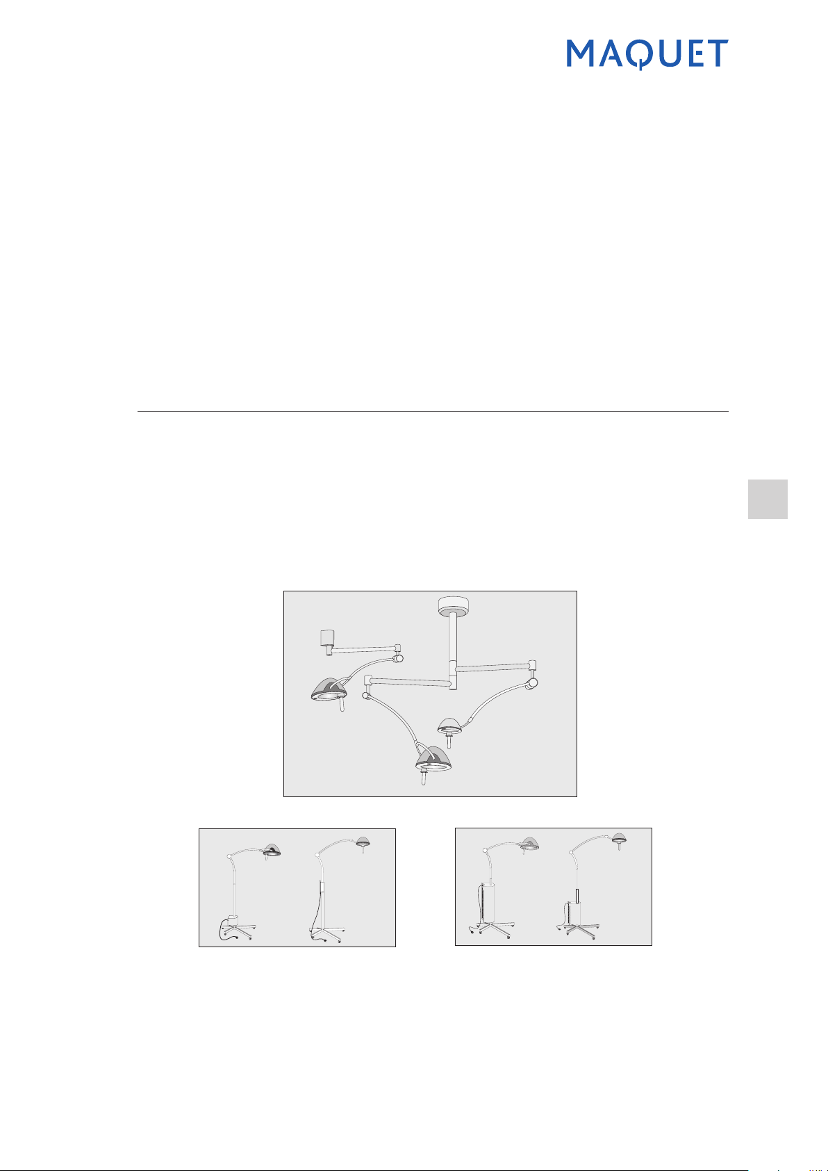
Ceiling, wall-mounted or mobile surgical light
Technical manual
EN
BLUELINE NT 0136201 EN Ed1A 01/08
Page 2

Ceiling, wall-mounted or
mobile surgical light
0136201
2
Technical manual
BLUELINE
Ceiling, wall-mounted or
mobile surgical lighting
CONTENTS
QUALITY STANDARDS COMPLIANCE ......................................................................................................3
SYMBOLS USED IN THESE INSTRUCTIONS ............................................................................................4
1 GENERAL CHARACTERISTICS ........................................................................................................5
2 CLEANING / DISINFECTION / STERILISATION ................................................................................6
2.1 Cleaning and disinfecting the surgical light ....................................................................................6
2.2 Cleaning and sterilising the handles ...............................................................................................6
3 GENERAL MAINTENANCE ................................................................................................................8
3.1 Preventive maintenance .................................................................................................................8
3.2 First level maintenance ..................................................................................................................8
3.3 Changing the bulb ........................................................................................................................11
3.4 Adjusting the balance ...................................................................................................................15
3.5 Adjusting the top limit stop of the BLUE 80 lighthead
3.6 Adjusting the lighthead brake .......................................................................................................17
3.7 Removing and installing the BLUE 30 lighthead ..........................................................................19
3.8 Removing and installing the BLUE 80 lighthead ..........................................................................21
3.9 Checking the BLUE 30/80 HOSPITAL .........................................................................................22
4 MAINTENANCE PROCEDURES ......................................................................................................24
4.1 BLUE 30 .......................................................................................................................................24
4.2 BLUE 80 .......................................................................................................................................27
5 SPARE PARTS AND MAINTENANCE KITS ....................................................................................34
5.1 BLUE 30 .......................................................................................................................................34
5.2 BLUE 80 .......................................................................................................................................36
6 ELECTRICAL INSTALLATION .........................................................................................................38
6.1 Suggested electrical installation ...................................................................................................38
6.2 Ceiling-mounted BLUE 30 ...........................................................................................................40
6.3 Ceiling-mounted BLUE 80 ...........................................................................................................41
6.4 BLUE 30 MOBILE ........................................................................................................................42
6.5 BLUE 80 MOBILE ........................................................................................................................43
6.6 BLUE 30 HOSPITAL ....................................................................................................................44
6.7 BLUE 80 HOSPITAL ....................................................................................................................45
7 DIAGRAMS AND PARTS LISTS .......................................................................................................47
7.1 Ceiling-mounted BLUELINE .........................................................................................................47
7.2 Wall-mounted BLUELINE .............................................................................................................67
7.3 BLUELINE MOBILE .....................................................................................................................79
7.4 BLUELINE HOSPITAL .................................................................................................................87
7.5 Lightheads ....................................................................................................................................99
7.6 Power supply boxes ...................................................................................................................105
8 TROUBLESHOOTING .....................................................................................................................111
Page 3

Ceiling, wall-mounted or
mobile surgical light
0136201
3
Technical manual
BLUELINE
QUALITY STANDARDS COMPLIANCE
Certication of MAQUET SA’s quality system
LNE/G-MED certies that the quality system developed by MAQUET SA for design, implementation, sales,
installation and after-sales service of surgical lights complies with the requirements of the following interna-
tional standards:
• ISO 9001:2000
• NF EN ISO 13485:2004
Reference standards
The BLUE 30/80 surgical light was designed to comply with the following standards:
• EN ISO 14971:2000 Medical devices - Application of risk management to medical devices
(ISO 14971:2000)
• EN ISO 14971:2000/A1:2003
• EN 60601-1:1990 Medical electrical equipment - Part 1: General requirements for safety
Amendment A1:1993 to EN 60601-1:1990
Amendment A2:1995 to EN 60601-1:1990
Amendment A13:1996 to EN 60601-1:1990
• EN 60601-1-2:2001 Medical electrical equipment - Part 1-2: General requirements for safety Collateral standard: Electromagnetic compatibility - Requirements and tests
• EN 60601-1-4:1996 Medical electrical equipment - Part 1-4: General requirements for safety -
Collateral standard: Programmable electrical medical systems
Amendment A1:1999 to EN 60601-1-4:1996
• EN 60601-1-6:2004 Medical electrical equipment - Part 1-6: General requirements for safety -
Collateral standard: Usability
• EN 60601-2-41:2000 Medical electrical equipment - Part 2-41: Particular requirements for the safety of
surgical luminaires and luminaires for diagnosis
This product has been veried for compliance with the following additional standards: CAN/CSA-C22.2
No. 601.1-M90 (R2005) (includes national differences for Canada), EN 60601-1:1990 + A1:1993 + A2:1995
+ A13:1996, UL 60601-1, rst edition, 2006-04-26 (includes national differences for the USA).
This product only meets FCC/UL requirements when equipped with a MAQUET SA power supply.
CE labelling/intended use
Compliance with the requirements of Directive 93/42/EEC on medical devices has been assessed and
approved by LNE/G-MED. BLUE 30/80 surgical lights belong to Class I as described in Annex IX of Directive
93/42/EEC.
This range includes single or dual ceiling-mounted, single wall-mounted and mobile light units with or without
battery-backed power supply.
Page 4

Ceiling, wall-mounted or
mobile surgical light
0136201
4
Technical manual
BLUELINE
SYMBOLS USED IN THE MANUAL
Symbol Meaning
F
Mandatory:
may affect patient or user safety
Recommendation:
risk of damage to device or accessories
CE mark: The device complies with the requirements of
European Directive 93/42/EEC on Medical Devices.
This device complies with Canadian and US safety
requirements.
Page 5

Ceiling, wall-mounted or
mobile surgical light
0136201
5
Technical manual
BLUELINE
1 GENERAL CHARACTERISTICS
(IN ACCORDANCE WITH STANDARD IEC 60 601-2-41)
Specications Unit BLUE 30 BLUE 80
Nominal illumination*
Nominal voltage V DC 22.8 22.8
Maximum power W 40 80
Colour temperature
Colour rendering index >85 >85
Illumination depth cm (inch) 175 (69) 140 (67)
Diameter d10
Diameter d50
With one mask % 0 % 6 %
lx
+/- 10%
K
+/-6%
cm (inch)
+/- 10%
cm (inch)
+/- 10%
35,000 90,000
4600 4600
17 (6.7) 16 (6.3)
10 (3.9) 10 (3.9)
With two masks % 62% 49 %
At base of tube % 100 % 100 %
Shadow dilution
With one mask, at base of tube % 0 % 6 %
With two masks, at base of tube % 62 % 49 %
Irradiance (Ee)* W/m
* Values measured during certication:
BLUE 30: 38.400 lx / 139 W/m
BLUE 80: 85.500 lx / 305 W/m
2
2
2
140 360
Page 6

Ceiling, wall-mounted or
mobile surgical light
0136201
6
Technical manual
BLUELINE
2 CLEANING / DISINFECTION / STERILISATION
Users must contact their hospital's sanitary specialists. The recommended products and procedures must
be applied. Should there be any doubt concerning the compatibility of active agents to be used, contact the
local Maquet customer service department.
2.1 Cleaning and disinfecting the surgical light
F
2.1.1 General instructions concerning cleaning, disinfection and safety
• Remove the sterilisable handles.
• Clean the system using a cloth soaked in surface detergent, in line with the manufacturer's recom-
• Use a cloth to rinse the unit with clean water and wipe dry.
• Disinfect uniformly using a cloth soaked in a disinfectant, in line with the manufacturer’s recommenda-
• Use a cloth to rinse with clean water in order to remove residues (in particular products containing al-
• Wipe with a dry cloth.
2.1.2 Examples of recommended products
Getinge USA product: TEC-QUAT 256
Anios products: SURFA’SAFE, 0.5% HEXANIOS G + R (ammonium IV, polyhexanide); ANIOSYME P.L.A
(quaternary ammonium, enzymes); SALVANIOS pH10 (quaternary ammonium, guanidinium); ANIOS DDSH
(quaternary ammonium, guanidinium).
Schülke & Mayr products: Antifect Plus (Glyoxal), Terralin (Benzyl-C12-18-alkyldimethyl ammonium, phe-
noxypropan and phenoxypropanol).
2.1.3 Examples of prohibited products
F
Check that the power is switched off and the light is cool before cleaning.
mended dilution, application time and temperature.
tions.
dehydes, quaternary ammonium or surfactants).
Solutions containing glutaraldehyde, phenol, iodine, bleach, alcohol or chloride ions must not be
used.
Fumigation methods are unsuitable for disinfecting the unit and must not be used.
2.2 Cleaning and sterilising the handles
2.2.1 Before cleaning
• Use a soft cloth immediately after use to wipe away soiling from the handle surface.
• Store handles in a place that keeps them moist to make further cleaning easier.
• Take care to store them in such a way that the inside does not get soiled.
2.2.2 Cleaning
• Soak the handles in a detergent solution.
• Soak for 15 minutes to allow the solution to act, then clean by hand with a soft brush and a lint-free
cloth.
• During cleaning, check regularly that the handles are fully clean and that no soiling remains on the
inside or outside.
• If any soiling remains, repeat cleaning or use an ultrasonic cleaning process.
• Rinsing: Rinse thoroughly in clean water to completely eliminate the detergent solution.
• Drying: Wipe with a clean lint-free cloth.
1
Never soak the handles in enzyme-based detergents as they may damage the material used; rinse thoroughly if
these detergents are used.
1
Page 7

Ceiling, wall-mounted or
mobile surgical light
0136201
7
Technical manual
BLUELINE
2.2.3 Washing and disinfection
Handles may be disinfected by machine (Clean Maquet) and rinsed at a maximum temperature of 93°C.
Typical recommended cycles:
2.2.4 Sterilisation
Step Temperature Time
Pre-wash 18 - 35°C 60 sec
Wash 46 - 50°C 300 sec
Neutralisation 41 - 43°C 30 sec
Wash 2 24 - 28°C 30 sec
Rinse 92 - 93°C 600 sec
Dry 20 min
After cleaning, the handles must be steam sterilised as set out below:
Countries
USA & Canada Prevacuum
France
Other countries Prevacuum Comply with national regulations
Sterilisation cycle
2
ATNC (Prion)
(Prevacuum)
Temperature [°C] Time [min] Drying [min]
132 - 135 10 16
134 18
• Check that each handle is clean before continuing the process.
• Wrap the handles with sterilisation wrapper material (double wrapper or equivalent).
Handles may also be placed in paper or plastic sterilisation bags3, for easier identication and reuse.
• Place the handles on steriliser trays with the opening downwards.
• Package with biological and/or chemical indicators for monitoring the sterilisation process, in accord-
ance with applicable regulations.
• Run the sterilisation cycle according to the steriliser manufacturer's instructions.
F
F
• Dispose of sterilisable handles in the same way as other hazardous products in a hospital environ-
To ensure correct sterilisation do not allow any soiling to penetrate inside the handle.
Handles are not guaranteed beyond 350 sterilisation cycles with the above sterilisation param-
eters.
ment.
4
2
This handle is made of a porous material.
3
Possible sterilisation bag suppliers:
Medical Action Industries
SBW Medical
Baxter International
4
For air removal and faster drying.
Page 8

Ceiling, wall-mounted or
mobile surgical light
0136201
8
Technical manual
BLUELINE
3 GENERAL MAINTENANCE
Isolate the surgical light from all electrical power sources and/or check that it is connected to an
isolating transformer at very low voltage.
If the spring arm is not disabled when dismantling the lighthead, the arm may spring up abruptly
and present a hazard. The rst step is therefore to disable the spring arm.
The light unit becomes hot during operation. Allow it to cool down before any maintenance or
repair work.
3.1 Preventive maintenance
To preserve your surgical light’s original performance and reliability, annual maintenance and inspections
should be performed as follows:
• By a Maquet technician or Maquet-approved distributor during the guarantee period.
• By a Maquet technician or Maquet-approved distributor or by the hospital's technical maintenance de-
partment outside the guarantee period (contact your dealer to arrange the required technical training).
3.2 First level maintenance
3.2.1 Daily inspection (user)
• Check that the bulbs operate correctly.
• Check that the sterilisable handle locks correctly in place, and replace it if not.
• Check the arm position.
• If a backup power supply is installed, check that the light would operate correctly if a power cut were to
occur.
• Check the overall condition of the unit: paintwork in good condition, screws fastened tightly, bezels and
covers in position.
3.2.2 Annual inspection (must be performed by an authorised technician)
• Check that the limit stops are in place and in good condition.
• Check and tighten the brakes.
• Check the bulb holder and replace if necessary.
• Check that the lighthead limit stops are in place and in good condition.
• For the BLUE HOSPITAL, check the battery autonomy and the backup supply changeover system (see
section 5.4).
• Check that the underside is in good condition and replace it if necessary.
Safety items
Check the following points:
• Attachment screws on suspension tube correctly tightened, seals in position.
• Arm(s) correctly mounted.
• All covers and caps installed.
Other checks
• Nominal illumination: see technical data.
• Earth continuity: 0.1 Ohm maximum.
• Suspension tube vertical.
• Balancing system adjusted correctly.
• Sterilisable handle locking mechanism.
• Voltage.
Page 9

Ceiling, wall-mounted or
mobile surgical light
0136201
9
Technical manual
BLUELINE
Dismantling certain elements may affect operation and safety. For example:
• Servicing the electrical power supply.
• Servicing the suspension arm and balance system.
• Servicing the optical system of lightheads equipped with lters designed to eliminate radiation not
visible to the patient. Surgical lights must never be used without these lters.
Contact the authorised Maquet after-sales service department for this type of inspection.
Page 10
Ceiling, wall-mounted or
mobile surgical light
0136201
10
Technical manual
BLUELINE
BLUE 30
2
1
Figure 1
3
Figure 3
4
Figure 2
Figure 4
Figure 5
Figure 7
Figure 6
Page 11

Ceiling, wall-mounted or
mobile surgical light
0136201
11
Technical manual
BLUELINE
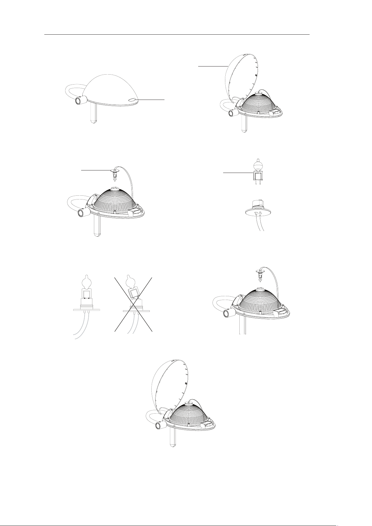
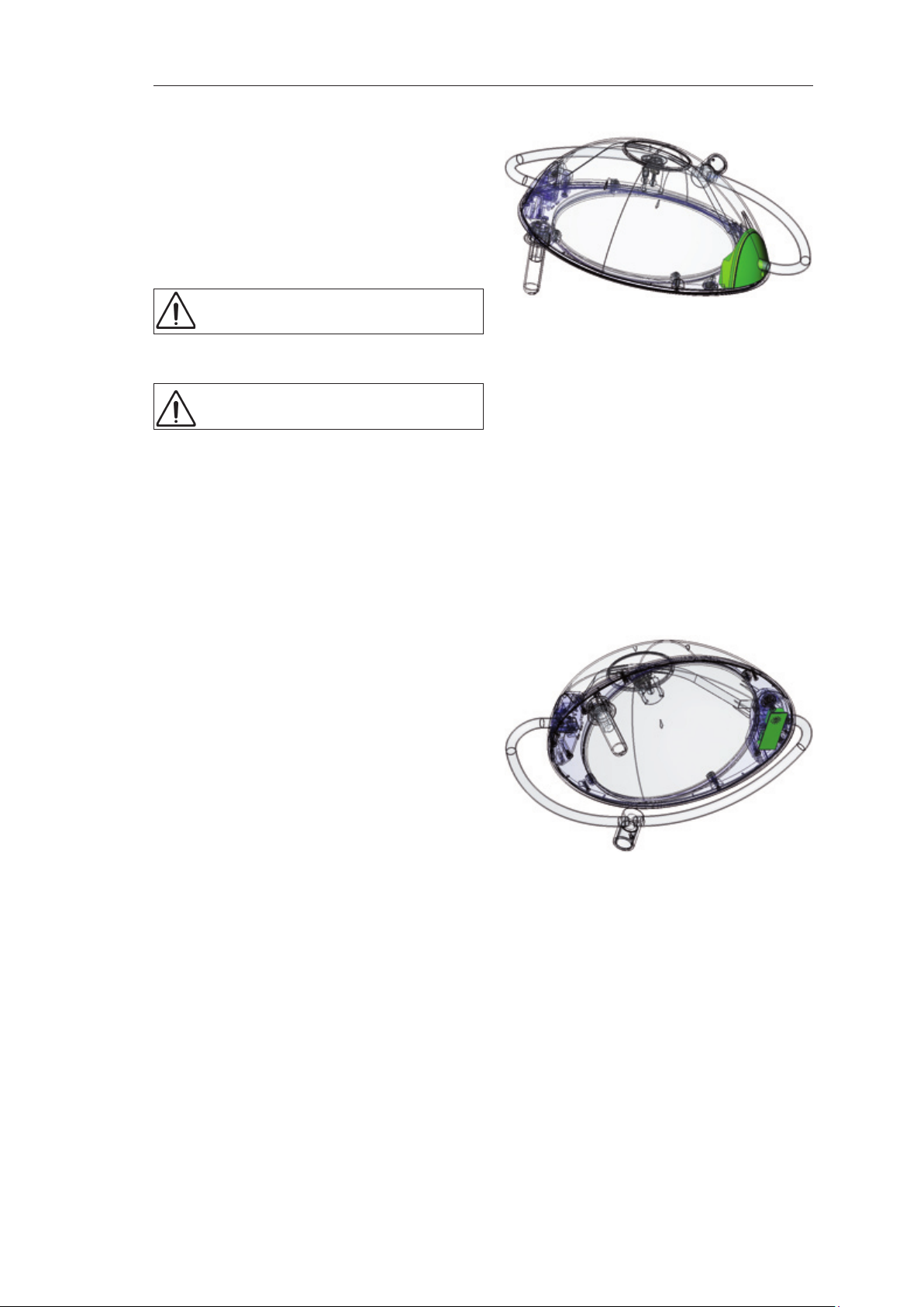
3.3 Changing the bulb
BLUE 30 lighthead
F
Figures 1 and 2
• Press the locking tab (1) and raise the casing of the failed bulb (2).
Figure 3
• Remove the bulb holder (3), taking care not to knock the hot bulb against any surfaces.
Figure 4
• Take the failed bulb (4) and remove it from the holder.
• Take the new bulb and remove it from its packaging.
Figure 5
• Insert the bulb pins into the bulb holder as far as they can go.
• Check that the bulb is correctly seated.
F
Figure 6
• Replace the bulb holder (3) and check that the locking tab clicks audibly into place.
Figure 7
• Close the cover and check that the locking tab clicks audibly into place.
F
When changing a blown bulb:
• Switch off the power supply and leave the lighthead to cool for 25 minutes.
• Only use MAQUET bulbs.
• Handle bulbs carefully through a cloth or wearing gloves.
• Never touch bulbs with bare hands. Grease on bulbs can shorten their life.
Do not change bulbs during an operation.
The unit is designed to operate with the cover closed. When conducting maintenance, take precautions to avoid touching surfaces marked as hot with the following symbol:
To avoid failures during operations, we recommend changing the bulbs on a preventive basis
every 600 hours.
If the bulb cannot be inserted fully, do not force it beyond the limit stop.
Check that the cover is correctly in place.
Page 12

Ceiling, wall-mounted or
mobile surgical light
0136201
12
Technical manual
BLUELINE
BLUE 80
4
Spare bulb
Figure 1
1
Figure 2
1
1
3
Main bulb
2
Figure 3
Figure 5
2
1
Figure 4
5
Figure 6
1
Figure 7
Figure 8
Page 13
Ceiling, wall-mounted or
mobile surgical light
0136201
13
Technical manual
BLUELINE
BLUE 80 lighthead
F
Figures 1 and 2
• Push the cover in slightly (1) and slide it sideways.
Figures 3 and 4
• First remove the main bulb holder (3), then the spare bulb holder (4), taking care not to knock the hot
Figure 5
• Take the failed bulb (5) and remove it from the holder.
• Take the new bulb and remove it from its packaging.
• Insert the bulb pins into the bulb holder as far as they can go.
F
Figure 6
• Check that the bulb is correctly seated.
Figure 7
• Replace the spare bulb holder rst, then the main bulb holder, checking that the locking tab clicks audi-
Figure 8
• Close the cover (1) and check that it is correctly in place.
When changing a blown bulb:
• Switch off the power supply and leave the lighthead to cool for 20 minutes.
• Only use MAQUET bulbs.
• Handle bulbs carefully through a cloth or wearing gloves.
• Never touch bulbs with bare hands. Grease on bulbs can shorten their life.
Do not change bulbs during an operation.
The unit is designed to operate with the cover closed. When conducting maintenance, take precautions to avoid touching surfaces marked as hot with the following symbol:
To avoid failures during operations, we recommend changing the main and spare bulbs on a preventive basis every 750 hours.
The yellow indicator on the underside of the BLUE 80 lighthead is lit if the spare bulb is activated.
To avoid a total failure of the surgical light, change the main bulb as soon as possible. We recommended changing the spare bulb at the same time.
bulb against any surfaces.
If the bulb cannot be inserted fully, do not force it beyond the limit stop.
bly into place in each case.
Page 14

Ceiling, wall-mounted or
mobile surgical light
0136201
14
Technical manual
BLUELINE
2
1
1 Bezel on mobile arm of spring arm
2 Bezel on xed arm of spring arm
3 Adjustment nut
3
Figure 33
1
1 Bezel on mobile arm of spring arm
2 Set screw
Figure 34
2
Page 15
Ceiling, wall-mounted or
mobile surgical light
0136201
15
Technical manual
BLUELINE
3.4 Adjusting the balance
Figure 33
F
• Remove the bezel from the mobile arm of the spring arm (1) and, for the BLUE 80, the bezel from the
• Turn the adjustment nut (3) by no more than half a turn, holding the hexagon socket screw on the op-
• If the lighthead goes down, turn to the right.
• If the lighthead goes up, turn to the left.
• Check that the spring arm remains steady in each position.
• Replace the bezel(s).
3.5 Adjusting the lighthead top limit stop
Figure 34
F
• Carefully remove the bezel from the mobile arm of the spring arm (1).
• Position the lighthead at the maximum desired height.
• Tighten the two socket screws (2) until resistance is felt.
If the spring arm does not remain steady in all positions, the force of the spring in the arm can be
increased or decreased.
xed arm (2).
posite side in position for the BLUE 80.
BLUE 80
BLUE 80 lightheads can be adjusted so that the travel cannot exceed the ceiling height.
The spring arm may be damaged if the socket screws are not tightened evenly.
Tighten the socket screws uniformly.
Page 16

Ceiling, wall-mounted or
mobile surgical light
0136201
16
Technical manual
BLUELINE
BLUE 30
1
2
3
1 Locking tab
2 Brake screw
3 Retaining screw (do not loosen)
BLUE 80
2
Figure 35
1
Figure 36
1 Brake screw
2 Lighthead fork
Page 17

Ceiling, wall-mounted or
mobile surgical light
0136201
17
Technical manual
BLUELINE
3.6 Adjusting the lighthead brake
The lighthead brakes are adjusted during installation. Brakes, like all mechanical parts, are subject
to wear. If the lighthead no longer remains steady in all positions the brake must be readjusted.
The light unit becomes hot during operation. Allow it to cool down before adjusting the brake.
BLUE 30 lighthead
Figure 35
• Turn off the BLUE 30 lighthead and allow it to cool down.
• Press the locking tab (1) to remove the bezel.
• Adjust the lighthead braking by tightening or loosening the brake screw (2). The retaining screw (3)
holds the lighthead in place and must not be loosened.
• Close the cover and check that the locking tab clicks audibly into place.
• Check that the cover is correctly in place.
BLUE 80 lighthead
Figure 36
• Turn off the BLUE 80 lighthead and allow it to cool down.
• Adjust the lighthead braking by tightening or loosening the brake screw (1) above the lighthead fork
(2).
Page 18
Ceiling, wall-mounted or
mobile surgical light
0136201
18
Technical manual
BLUELINE
2
3
1
Figure 4
4 65
2
7
Figure 5
Page 19

Ceiling, wall-mounted or
mobile surgical light
0136201
19
Technical manual
BLUELINE
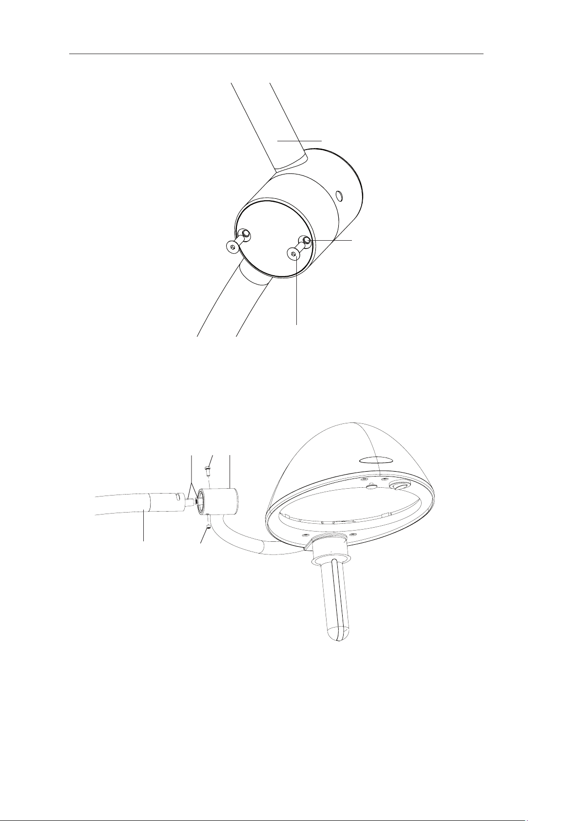
3.7 Removing and installing the BLUE 80 lighthead
If the spring arm is not disabled when removing the lighthead, the arm may spring up abruptly and
present a hazard.
• Lower the spring arm and lock it in a safe position when installing the lighthead.
• Assemble in the correct order: rst install the lighthead then enable the arm.
• Place the arm in the topmost position when removing the lighthead.
• Keep clear of the spring arm when enabling it.
Removing the BLUE 30 lighthead
Figure 4
• Place the spring arm (2) in the top position.
• Remove the two taper-head hex socket screws (1) to disable the spring arm.
Figure 5
F
• Unscrew the hexagon socket screw (5).
• Unscrew the brake screw (7).
• Remove the fork (6) from the spring arm and separate the connectors (4).
The hex socket screw (5) is a safety screw* that must be replaced each time the unit is
reassembled.
Reinstalling the BLUE 30 lighthead
Figure 4
F
• To disable the spring arm, unscrew the two taper-head hex socket screws (1).
Figure 5
• Secure the connectors (4).
F
• Insert the fork (6) in the spring arm (2) such that the hole in the spring arm lines up with the hole in the
• Lock the fork in place with the hex socket safety screw (5).
• Use a at screwdriver to tighten the brake screw (7).
Figure 4
• To enable the spring arm, tilt the lighthead and spring arm (2) upwards until the holes (3) line up with
• Install the two taper-head hex socket screws (1).
* Safety screws are available in packs of 5 (3 690 51 555).
The spring arm must be disabled before installing the BLUE 30 lighthead.
The hex socket screw (5) is a safety screw that must be replaced each time the unit is
reassembled.
fork.
the tappings (3).
Page 20

Ceiling, wall-mounted or
mobile surgical light
0136201
20
Technical manual
BLUELINE
1
2
4
8
2
5
76
3
Figure 9
Figure 10
Page 21
Ceiling, wall-mounted or
mobile surgical light
0136201
21
Technical manual
BLUELINE
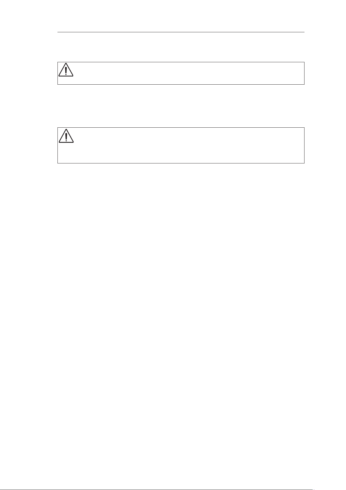
3.8 Removing and installing the BLUE 80 lighthead
The order of disassembly is important:
If the spring arm is not disabled when disassembling the BLUE 80 lighthead, the arm may spring
up abruptly and present a hazard. The rst step is therefore to disable the spring arm.
Disabling the BLUE 80 spring arm
Figure 9
• Remove the bezel (1) from the mobile side of the spring arm (2).
• Pivot the spring arm down to the oor and insert the locking pin (3) in hole (4).
If the locking pin is not inserted deeply enough in the hole the spring arm may spring up abruptly
and present a hazard.
Check that the spring arm correctly locked in place before releasing it.
Only use the supplied locking pin.
Removing the BLUE 80 lighthead
Figure 10
F
• Unscrew the hexagon socket screw (5).
• Unscrew the brake screw (6).
• Remove the fork (7) from the spring arm and separate the connectors (8).
Reinstalling the BLUE 80 lighthead
Figure 10
• Secure the connectors (8).
F
• Insert the fork in the spring arm such that the hole in the fork lines up with the hole in the ring.
• Lock the fork in place using the shakeproof hex socket screw (5) and the brake screw (6).
Enabling the BLUE 80 spring arm
Figure 9
• Lower the spring arm (2) and lighthead slightly by pressing on it.
• Remove the locking pin (3).
• Install the bezel (1) and check that it is correctly in place.
The hex socket screw (5) is a safety screw that must be replaced each time the unit is reassembled.
The hex socket screw (5) is a safety screw* that must be replaced each time the unit is
reassembled.
* Safety screws are available in packs of 5 (3 690 52 555).
Page 22

Ceiling, wall-mounted or
mobile surgical light
0136201
22
Technical manual
BLUELINE
3.9 Checking the BLUE 30/80 HOSPITAL
F
To ensure that the surgical light will operate correctly in the event of a power failure it must be
checked before each use.
LED 1
Check Mains
LED 1
Plug the light into
the power outlet
and turn it on
Disconnect the
power outlet (the
light should remain
on)
Testing the autonomy of the batteries in the BLUE 30/80 HOSPITAL light
F
To guarantee that the light will operate correctly in the event of a power cut, the battery autonomy
must be checked at least once a year, as part of preventive maintenance work.
Check Mains
Turn off the light
and charge the
batteries for at
least 14 hours
Turning on the light LED green LED off LEDs 3 to 8
Disconnect the
power outlet (the
light should remain
on)
BLUE 30:
After 1 hour's battery operation
BLUE 80:
After 4 hours' battery operation
Connect the power
outlet
LED green LED off LEDs 3 to 8
LED off LED yellow One of LEDs 3 to
LED 1
LED green LED off LEDs 3 to 8
LED off LED yellow One of LEDs 3 to
LED off LED yellow One of LEDs 3 to
LED green LED off LEDs 3 to 8
Batteries
LED 2
Batteries
LED 2
Charging
LEDs 3 to 8
scrolling
LED 8 ashes Batteries
8 lit
(battery charge
level)
Charging
LEDs 3 to 8
scrolling
LED 8 ashes Batteries
scrolling
LED 8 ashes Batteries
8 lit
(battery charge
level)
8 lit
(battery charge
level)
scrolling
LED 2
LEDs 3 to 8
Comment
Batteries charging
completely
charged
Operation on
batteries
Comment
Batteries charging
completely
charged
Batteries charging
completely
charged
Operation on
batteries
Operation on
batteries
Batteries charging
Page 23
Ceiling, wall-mounted or
mobile surgical light
0136201
23
Technical manual
BLUELINE
Anomalies
Operation Anomaly Likely cause Corrective action
On power outlet
(light on)
On batteries (light
on)
LED 1 not lit green Electronic fault Call Maquet technical
department
LED 2 lit yellow Mains fuse missing or
blown
LED 1 ashes red Charging circuit safety
fuse fault
LEDs 3 to 8 not scrolling;
LED 8 not lit
LED 2 not lit yellow Electronic fault Call Maquet technical
None of LEDs 3 to 8 lit Electronic fault Call Maquet technical
The light goes out when
the power outlet is
disconnected
LED 4 ashes Batteries discharged Recharge batteries
Electronic fault Call Maquet technical
Batteries faulty or
incorrectly connected
Charging circuit safety
fuse fault
Electronic fault (charger
board)
Change the fuse
Change the fuse
(quick-blow automotive
type, 7.5 A/32 V)
department
department
department
Check the connections
and change the batteries if
necessary
Change the fuse
(quick-blow automotive
type, 7.5 A/32 V)
Call Maquet technical
department
F
LED 3 lit red
LED 1 lit red
No warning is provided if the batteries are completely discharged or out of order. The fault may be
checked by disconnecting the power outlet. No indicators are lit in this case.
Batteries close to deep
discharge
Recharge batteries
urgently
Page 24

Ceiling, wall-mounted or
mobile surgical light
0136201
24
Technical manual
BLUELINE
4 MAINTENANCE PROCEDURES
Required tools
• Cross-head screwdriver
• Torx screwdriver
• Allen wrench
4.1 BLUE 30
4.1.1 Removing the BLUE 30 lighthead cover
• Press the tab.
• Lift the cover.
4.1.2 Reinstalling the BLUE 30 lighthead cover
• Proceed in reverse order.
Check that the tab is correctly located.
4.1.3 Replacing the reector subassembly
• Remove the BLUE 30 lighthead cover.
• Disconnect and remove the lamp bracket.
• Unscrew and remove the four screws and wash-
ers.
• Remove the reector subassembly.
The spacers (and lens) may adhere to the
reector slightly.
• Install the new reector subassembly on the
spacers.
• Put the screws in place.
• Tighten the screws.
• Connect and position the lamp bracket.
• Reinstall the BLUE 30 lighthead cover.
4.1.4 Replacing the lens
• Remove the BLUE 30 lighthead cover.
• Remove the reector subassembly.
• Remove the lens.
• Remove the four spacers from the lens.
• Take the new lens and place the four spacers 90°
apart.
• Place this assembly on the base of the BLUE 30
lighthead.
• Reinstall the reector subassembly.
• Reinstall the lamp bracket.
• Reinstall the BLUE 30 lighthead cover.
Page 25
Ceiling, wall-mounted or
mobile surgical light
0136201
25
Technical manual
BLUELINE
4.1.5 Replacing the spacers
Always change the four spacers at the
same time.
• Remove the BLUE 30 lighthead cover.
• Remove the reector subassembly.
• Remove the lens.
• Remove the four spacers.
• Place the four new spacers 90° apart on the lens.
• Place this assembly on the base of the BLUE 30
lighthead.
• Reinstall the reector subassembly.
• Reinstall the lamp bracket.
• Reinstall the BLUE 30 lighthead cover.
4.1.6 Replacing the underside
• Remove the BLUE 30 lighthead cover.
• Loosen the brake screw.
• Loosen the screw to allow the fork to slide.
• Unscrew the screw.
• Remove the sterilisable handle bracket.
The handle bracket may fall.
• Remove the screw.
• Remove the underside (with plastic washer and clip).
The underside may fall.
• Put the new underside in place.
• Re-attach the side with the clip.
• Install the sterilisable handle bracket.
• Tighten the screw holding the sterilisable handle bracket.
• Reposition the fork in the base of the BLUE 30 lighthead.
• Tighten the limit stop screw.
Check that it is correctly in place.
• Tighten the brake screw.
• Reinstall the BLUE 30 lighthead cover.
Page 26

Ceiling, wall-mounted or
mobile surgical light
0136201
26
Technical manual
BLUELINE
4.1.7 Replacing the switch
• Remove the BLUE 30 lighthead cover.
• Remove the switch, separating the pivoting head
from the rest of the switch.
• Disconnect the switch from the connectors.
• Connect the new switch.
The wires are colour-coded.
• Separate the pivoting head to put the switch in
place.
• Reinstall the BLUE 30 lighthead cover.
4.1.8 Replacing the fork
• Remove the lighthead from the spring arm.
• Remove the lighthead from the spring arm.
• Remove the BLUE 30 lighthead cover.
• Disconnect the connector connected to the lamp
• Disconnect the connectors from the switch.
• Unscrew the brake screw to release the fork.
• Unscrew the limit stop screw.
• Remove the fork from the base of the BLUE 30
• Slide the wiring through rst.
• Position the fork in the base of the BLUE 30
• Tighten the limit stop screw.
• Tighten and adjust the brake screw.
• Connect the connectors to the switch.
The spring arm may spring up sharply.
bracket.
lighthead along with the wiring.
body.
Check that it is correctly in place.
The wires are colour-coded.
• Connect the connector to the lamp bracket.
• Reinstall the BLUE 30 lighthead cover.
Page 27

Ceiling, wall-mounted or
mobile surgical light
0136201
27
Technical manual
BLUELINE
4.1.9 Replacing the lamp bracket
• Remove the BLUE 30 lighthead cover.
• Disconnect the lamp bracket.
• Remove the lamp bracket from the reector
subassembly.
• Connect the new lamp bracket.
• Place the lamp bracket on the reector.
• Reinstall the BLUE 30 lighthead cover.
Page 28

Ceiling, wall-mounted or
mobile surgical light
0136201
28
Technical manual
BLUELINE
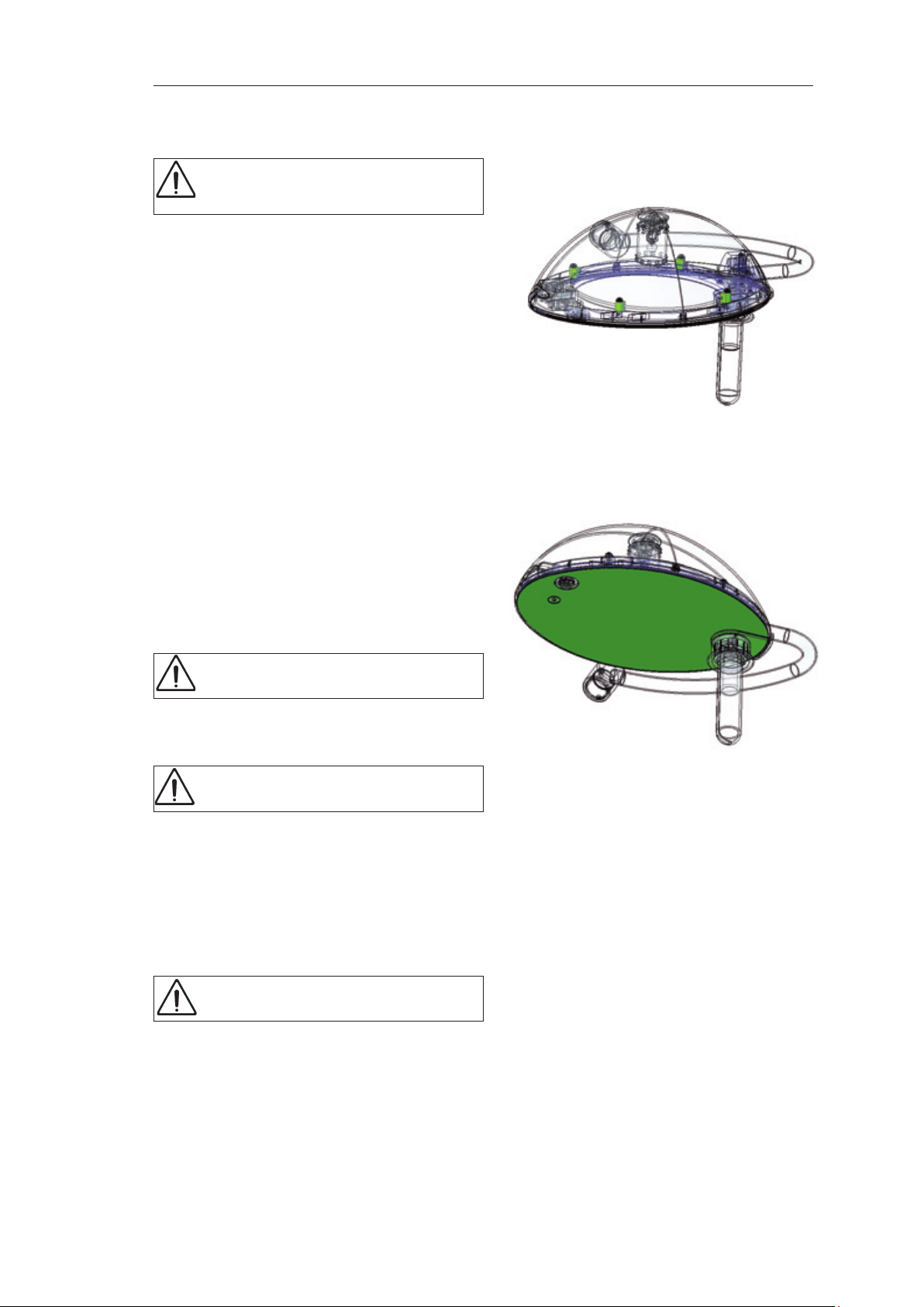
4.2 BLUE 80
4.2.1 Removing the BLUE 80 lighthead cover
• Remove the four central screws from the underside.
• Remove the BLUE 80 cover.
4.2.2 Reinstalling the BLUE 80 lighthead cover
• Put the BLUE 80 cover in place.
• Tighten the four screws.
4.2.3 Replacing the reector subassembly
• Remove the BLUE 80 cover.
• Remove the lamp brackets from the reector.
• Unscrew and remove the four screws and washers.
• Remove the reector subassembly.
Avoid touching the inside of the reector.
• Install the new reector subassembly on the spacers.
Ensure that it is correctly oriented relative
to the fork.
• Put the screws in place and tighten them.
• Put the lamp brackets back in position.
• Reinstall the BLUE 80 cover.
4.2.4 Replacing the lens
• Remove the BLUE 80 cover.
• Remove the reector subassembly.
• Remove the lens.
• Remove the four spacers from the lens.
• Take the new lens and put the four spacers in place.
• Place the assembly on the base of the BLUE 80.
• Reinstall the reector subassembly.
• Reinstall the lamp brackets.
• Reinstall the BLUE 80 cover.
Page 29

Ceiling, wall-mounted or
mobile surgical light
0136201
29
Technical manual
BLUELINE
4.2.5 Replacing the spacers
Always change the four spacers at the
same time.
• Remove the BLUE 80 cover.
• Remove the reector subassembly.
• Remove the lens.
• Remove the four spacers from the lens.
• Put the four new spacers in place.
• Place the assembly on the base of the BLUE 80.
• Reinstall the reector subassembly.
• Reinstall the lamp brackets.
• Reinstall the BLUE 80 cover.
4.2.6 Replacing the underside
• Remove the six visible screws from the underside.
Four of these six screws hold the cover in
place. It may fall after they are removed.
• Remove the two screws from the sterilisable handle bracket.
The underside may fall.
• Put the new underside in place.
• Install the sterilisable handle bracket.
• Tighten the screws holding the sterilisable han-
dle.
• Tighten the six visible screws on the underside.
• Ensure that the two short screws are placed at
the join with the ends of the fork.
• Reinstall the BLUE 80 cover.
4.2.7 Replacing the switch
• Remove the BLUE 80 cover.
• Remove the switch, separating the pivoting head
from the rest of the switch.
• Disconnect the connectors from the switch.
• Connect the new switch.
• Separate the pivoting head to put the switch in
place.
• Reinstall the BLUE 80 cover.
Page 30

Ceiling, wall-mounted or
mobile surgical light
0136201
30
Technical manual
BLUELINE
4.2.8 Replacing the ap
• Remove the BLUE 80 cover.
• Remove the reector subassembly.
Take care not to let the lens fall.
• Unscrew the two screws holding the ap.
• Check the ap.
• Put the new ap in place.
• Tighten the two screws holding the ap.
• Reinstall the reector subassembly.
• Reinstall the BLUE 80 cover.
4.2.9 Replacing the fork bracket
• Remove the BLUE 80 cover.
• Remove the reector subassembly.
• Remove the ap.
Remove the lens to avoid it falling by accident.
• Remove the underside.
• If both fork brackets are to be replaced, remove
and reinstall one fork at a time.
Left side:
• Unscrew (but do not remove) the screw from the
limit stop.
• Remove the four screws.
• Remove the fork bracket from the base and from
the fork.
• Install the new fork bracket.
Check that the limit stop screw, brake
screw and nut are in place on the new fork
bracket.
• Tighten the four screws holding the fork bracket
to the base.
• Position the fork bracket correctly in the fork.
• Tighten the limit stop screw.
Page 31
Ceiling, wall-mounted or
mobile surgical light
0136201
31
Technical manual
BLUELINE
Right side:
• Remove the switcher board from its slot.
• Disconnect the wires from the board.
• Remove the four screws.
• Remove the fork bracket from the base of the
fork.
• Install the new fork bracket.
Check that the brake screw and nut are in
place on the new fork bracket.
• Tighten the four screws holding the fork bracket
to the base.
Ensure that all cables are in place before
tightening.
• Connect the wires to the switcher board.
• Place the switcher board in its slot.
• Reinstall the underside.
• Reinstall the ap.
• Reinstall the lens.
• Reinstall the reector subassembly.
• Reinstall the BLUE 80 cover.
4.2.10 Replacing the switcher board
• Remove the BLUE 80 cover.
• Remove the underside.
• Remove the switcher board from its slot.
• Disconnect the wires.
• Connect the wires to the new switcher board.
• Place the switcher board in its slot.
• Reinstall the underside.
• Reinstall the BLUE 80 cover.
Page 32

Ceiling, wall-mounted or
mobile surgical light
0136201
32
Technical manual
BLUELINE
4.2.11 Replacing the lamp brackets
• Remove the BLUE 80 cover.
• Remove the underside.
• Disconnect the connectors from the lamp brack-
ets.
• Unscrew (but do not remove) the screws holding
the fork bracket, to release the cables to the new
lamp brackets on the switcher board.
• Connect the new lamp bracket connectors to the
switcher board.
• Place the switcher board in its slot.
• Reinstall the underside.
• Reinstall the BLUE 80 cover.
4.2.12 Replacing the fork
• Remove the lighthead from the spring arm.
Take care as the spring arm may spring
up.
• Remove the BLUE 80 cover.
• Remove the underside.
• Remove the reector subassembly.
• Remove the lens (and spacers).
• Remove the ap.
• Remove the fork brackets.
• Remove the fork.
• Take the new fork.
• Reinstall the fork brackets and fork on the base
of the lighthead.
• Reinstall the underside.
• Reinstall the lens.
• Reinstall the ap.
• Reinstall the reector subassembly.
• Reinstall the BLUE 80 cover.
Ensure that the limit stop screw ts properly
into the slit. Do not overtighten.
• Reinstall the lighthead on the spring arm.
Page 33

Ceiling, wall-mounted or
mobile surgical light
0136201
33
Technical manual
BLUELINE
Page 34

Ceiling, wall-mounted or
mobile surgical light
0136201
34
Technical manual
BLUELINE
5 SPARE PARTS AND MAINTENANCE KITS
5.1 BLUE 30 spare parts and maintenance kits
The quantities listed are those included in the kit.
Part number Description Quantity
5 690 03 039 BLUE 80/30 single 850 cable 1
5 690 03 040 BLUE 80/30 duo 1000 cable 1
5 690 10 106 BLUE 30-80 wall-mounting cover 1
5 690 03 038 BLUE 80/30 850 cable 1
5 690 10 102 BLUE 30 spring arm cap 1
5 605 17 82 50-ZIO x 35.5 caster with brake (set of 2) 2
5 605 17 84 Assembly kit for 3/5 legs
M8 x 35 CHc screw DIN 912 5
8.4 mm star washer DIN 6797 5
M8 x 22 CHc screw DIN 912 1
M8 nut DIN 934 5
5 690 14 026 BLUE 30 stand star section 1
3 690 57 555 Set of 10 5x20 3.15 A quick-blow fuses 10
5 607 52 05 Mains cable (Europe) 1
5 607 52 05 Mains cable (US) 1
5 690 05 624 BLUE 30 body 1
3 690 03 997 BLUE 30 reector S/A
5 690 05 004 BLUE 30 Reector 1
5 690 05 021 Spring blanking plate - machined 1
6 000 80 306 Pan-head cross-head screw - 6 lobes - zinc-plated steel - M3 x 6 4
5 690 05 024 BLUE 30 glass tube 1
5 690 05 020 Spring blanking plate 1
6 566 00 011 Spring bush - hex socket - stainless steel - M4 x 9 4
6 014 10 402 H 0.8 M4 nut - stainless steel 1
5 690 05 070 Bracket 1
3 690 40 555 BLUE 30 spacer kit
5 690 05 060 BLUE 30 spacer 4
6 009 90 040 Plastic raised countersunk head screw - Pozidriv - L 20 - Ø 4 4
6 023 70 043 Flat washer - Ø8 - Ø4.3 - thickness 0.5 mm - zinc-plated steel 4
3 690 50 555 BLUE 30 underside replacement kit
5 690 05 002 Underside 1
5 665 31 87 Plastic washer 1
5 607 72 72 Clip 1
6 000 80 306 Pan-head cross-head screw - 6 lobes - zinc-plated steel - M3 x 6 1
6 024 20 306 Flat washer - Ø6 - Ø3.2 - thickness 0.5 mm - zinc-plated steel 1
Page 35

Ceiling, wall-mounted or
mobile surgical light
0136201
35
Technical manual
BLUELINE
3 690 51 555 Set of BLUE 30 safety screws (pack of 5)
6 007 70 410 Low-prole pan head Torx screw - M4 x 10 - stainless steel 5
5 690 05 034 BLUE 30 - lens 1
5 605 17 83 Caster 50 210 - 35.5 (pack of 2) 2
5 605 31 53 3-track brushes 1
5 690 10 104 Bumper 1
3 693 01 555 Pack of 10 miniature 7.5 A 32 V quick-blow fuses 10
3 643 02 555 BLUE plastic ring with bearings 1
3 690 08 998 Diode bridge kit
3 693 06 555 BLUE 30 wall/ceiling-mounted adjustable power supply
3 693 07 555 BLUE 30 MOBILE adjustable power supply (Europe)
3 693 08 555 BLUE 30 MOBILE adjustable power supply (US)
3 693 03 555 BLUE 30/80 HOSPITAL power supply
3 690 09 997 New B30 fork S/A
Page 36

Ceiling, wall-mounted or
mobile surgical light
0136201
36
Technical manual
BLUELINE
5.2 BLUE 80 spare parts and maintenance kits
Part number Description Quantity
5 690 03 039 BLUE 80/30 single 850 cable 1
5 690 03 040 BLUE 80/30 duo 1000 cable 2
5 690 10 106 BLUE 30-80 wall-mounting cover 1
5 690 42 999 BLUE 80 wall/ceiling-mounted spring arm 1
5 690 03 038 BLUE 80/30 850 cable 1
3 690 10 997 BLUE 80 MOBILE mains cable loom S/A
5 690 03 031 Wiring 1
6 914 00 095 KEC mains connector (BLUE 30/80) 1
6 890 04 520 2-pole fuse drawer without mains cut-out 1
5 601 89 21 Sleeve 1
6 936 00 020 5x20 3.15 A quick-blow fuse 2
3 690 57 555 Set of 10 5x20 3.15 A quick-blow fuses
3 690 11 997 BLUE 80 MOBILE power supply cable outlet loom
6 887 00 02 Ferrite 1
5 690 03 029 BLUE 80 power supply cable outlet 1
5 607 52 05 Mains cable (Europe) 1
5 607 52 05 Mains cable (US) 1
5 690 10 100 BLUE 80 spring arm cap 1
5 690 05 035 BLUE 80 - lens 1
5 601 97 05 Switch assembly 1
5 690 03 016 Circuit board 1
3 690 04 997 BLUE 80 reector S/A
5 690 05 042 Painted bezel 1
5 690 05 041 Bezel bracket 3
6 000 80 306 Pan-head cross-head screw - 6 lobes - zinc-plated steel - M3 x 6 3
5 690 05 005 BLUE 80 - reector 1
5 690 05 080 Bracket 1
6 566 00 011 Spring bush - hex socket - stainless steel - M4 x 9 1
6 014 10 402 H 0.8 M4 nut - stainless steel 1
3 690 42 555 BLUE 80 spacer kit
5 690 05 061 BLUE 80 spacer 4
6 009 90 041 Plastic raised countersunk head screw - Pozidriv - L 20 - Ø 5 4
6 021 81 652 Flat washer - Ø16 - Ø5.3 - thickness 1 mm - stainless steel 4
3 690 54 555 BLUE 80 ap kit
5 601 95 21 Plastic raised countersunk head screw - Pozidriv - L 8 - Ø 5 2
5 690 05 630 BLUE 80 ap assembly 1
Page 37

Ceiling, wall-mounted or
mobile surgical light
0136201
37
Technical manual
BLUELINE
3 690 53 555 Fork bracket kit
5 690 05 616 BLUE 80 fork bracket 1
5 665 20 68 Square nut 10x10 - M6 - thickness 5 mm 1
5 607 73 04 Modied screw 1
5 665 04 70 Raised countersunk head screw - Pozidriv - M4 x 8 1
3 690 52 555 Set of BLUE 80 safety screws (pack of 5)
6 012 40 510 Low-prole pan head Torx screw - M5 x 10 - stainless steel (x5) 1
3 690 55 555 BLUE 80 handle bracket kit
5 690 05 621 BLUE 80 sterilisable handle bracket - assembled 1
6 009 50 430 Pan head screw - 6 lobes - stainless steel - M4 x 30 2
3 690 08 999 Fork S/A
5 690 03 015 BLUE 80 fork cable kit
5 607 78 57 BLUE 80 fork ring 1
6 005 80 504 Hex socket set screw - M5 x 4 - stainless steel 1
6 012 40 510 Low-prole pan head Torx screw - M5 x 10 - stainless steel (x5) 1
5 690 05 515 Fork 1
3 690 05 999 Spare bulb holder
5 690 03 012 B80 halogen socket, wired 1
5 690 05 082 Socket bracket 80 - 2 1
6 012 50 312 Pan head screw - 6 lobes - M3x12 - stainless steel 2
3 690 06 997 Main bulb holder
5 690 03 012 B80 halogen socket, wired 1
5 690 05 081 Socket bracket 80 - 1 1
6 012 50 312 Pan head screw - 6 lobes - M3x12 - stainless steel 2
5 605 31 53 3-track brushes 1
5 690 10 104 Bumper 1
3 693 01 555 Pack of 10 miniature 7.5 A 32 V quick-blow fuses 10
3 643 02 555 BLUE plastic ring with bearings 1
3 690 08 998 Diode bridge kit
3 693 05 555 BLUE 80 wall/ceiling-mounted power supply
3 693 04 555 BLUE 80 MOBILE power supply
3 693 03 555 BLUE 30/80 HOSPITAL power supply
3 693 07 555 Pack of 5 x 6.3 A fuses for B80 circuit board
Page 38

Ceiling, wall-mounted or
mobile surgical light
0136201
38
Technical manual
BLUELINE
6 ELECTRICAL INSTALLATION
6.1 Suggested electrical installation
Installation components
E1M BLUE 30 or BLUE 80 lighthead
F1F Fuse for indicators
K1N +
K2N
Q1M Main switch
T1M power supply
H1H Red LED, backup supply operating
H2H Green LED, main power supply operating
Technical characteristics of components
Component Technical characteristics Part number
K1N + K2N
Measurement relays
T1M
Voltage control relay
24 V DC ARD 6 886 00 220
BLUE 30 100-230 V 50/60 Hz 70 VA ARD 5 690 03 018
BLUE 80 100-230 V 50/60 Hz 120 VA ARD 5 690 39 999
Page 39

Ceiling, wall-mounted or
mobile surgical light
0136201
39
Technical manual
BLUELINE
(13)
A1
(14)
A2
(9)
11
(1)
12
(5)
14
(12)
41
(4)
42
(8)
44
(13)
A1
(14)
A2
(9)
11
(1)
12
(5)
14
(12)
41
(4)
42
(8)
44
T1M
N
L
L1
N
PE
PA
+24Vdc
0V
Q1M
E1M
KN1
K2N
H2HH1H
F1F
E1M
+24V dc 0V
Page 40

Ceiling, wall-mounted or
mobile surgical light
0136201
40
Technical manual
BLUELINE
N
L
-
+
6.2 Ceiling-mounted BLUE 30
5 600 41 27
Suspension
5 600 41 29
anchorage
main arm
spring arm
mauve
5 690 03 39
5 600 44 83
black
switch
white
lighthead
grey
grey
bulb
Page 41

Ceiling, wall-mounted or
mobile surgical light
0136201
41
Technical manual
BLUELINE
6.3 Ceiling-mounted BLUE 80
anchorage
5 690 03 030
MPS 120 - 228 power supply
lighthead + fork
5 690 03 028
6.3 A fuse
spare bulb
grey
main bulb
grey
circuit board
black
switch
white
black
suspension
5 600 41 29
5 600 41 27
5 690 03 039
main arm
spring arm
5 600 44 84
Page 42
Ceiling, wall-mounted or
mobile surgical light
0136201
42
Technical manual
BLUELINE
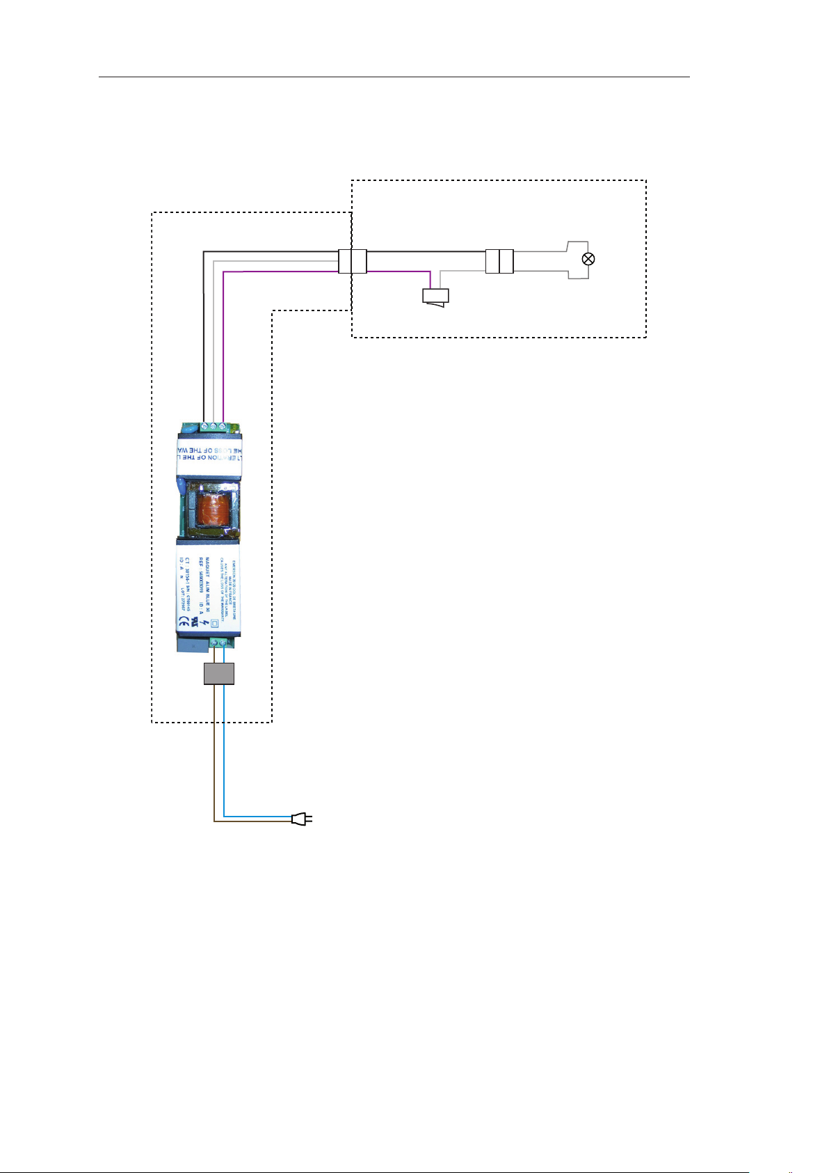
6.4 BLUE 30 MOBILE
spring arm
lighthead
black
white
mauve
black
mauve
switch
white
grey
bulb
grey
brown
ferrite
blue
Page 43

Ceiling, wall-mounted or
mobile surgical light
0136201
43
Technical manual
BLUELINE
N
L
6.5 BLUE 80 MOBILE
transformer unit
spare bulb
grey
6.3 A fuse
lighthead + fork
main bulb
grey
circuit board
black
switch
white
black
white
MPS 120 - 228 power supply
white
24 V
black
blue
brown
green/yellow
3.15 A fuse
110 V/220 V
0 V
ferrite
straight tube
black
vertical tube
white
black
spring arm
Page 44

Ceiling, wall-mounted or
mobile surgical light
0136201
44
Technical manual
BLUELINE
- 0 V
N
L
+15 V
+
+
-
-
6.6 BLUE 30 HOSPITAL
transformer unit
black
mauve
bulb
white
switch
black
lighthead
batteries
black
mauve
red
black white
spring arm
brown
3.15 A fuse
110 V/220 V
blue
green/yellow
black
white
mauve
black
MPS 120 - 15 power supply
ferrite
charger board
mini. 7.5 A fuse
Page 45
Ceiling, wall-mounted or
mobile surgical light
0136201
45
Technical manual
BLUELINE
- 0 V
N
L
+15 V
+- +-
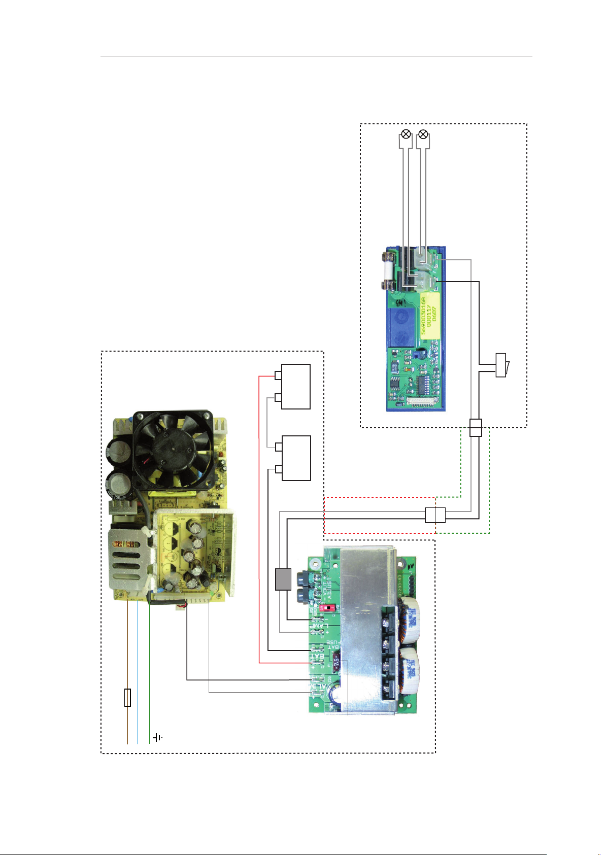
6.7 BLUE 80 HOSPITAL
transformer unit
spare bulb
grey
6.3 A fuse
lighthead + fork
main bulb
grey
black
white
black
circuit board
switch
batteries
white
red
black white
vertical tube
black
spring arm
MPS 120 - 15 power supply
blue
brown
green/yellow
3.15 A fuse
black
white
white
ferrite
black
charger board
110 V/220 V
mini. 7.5 A fuse
Page 46

Ceiling, wall-mounted or
mobile surgical light
0136201
46
Technical manual
BLUELINE
Page 47

Ceiling, wall-mounted or
mobile surgical light
0136201
47
Technical manual
BLUELINE
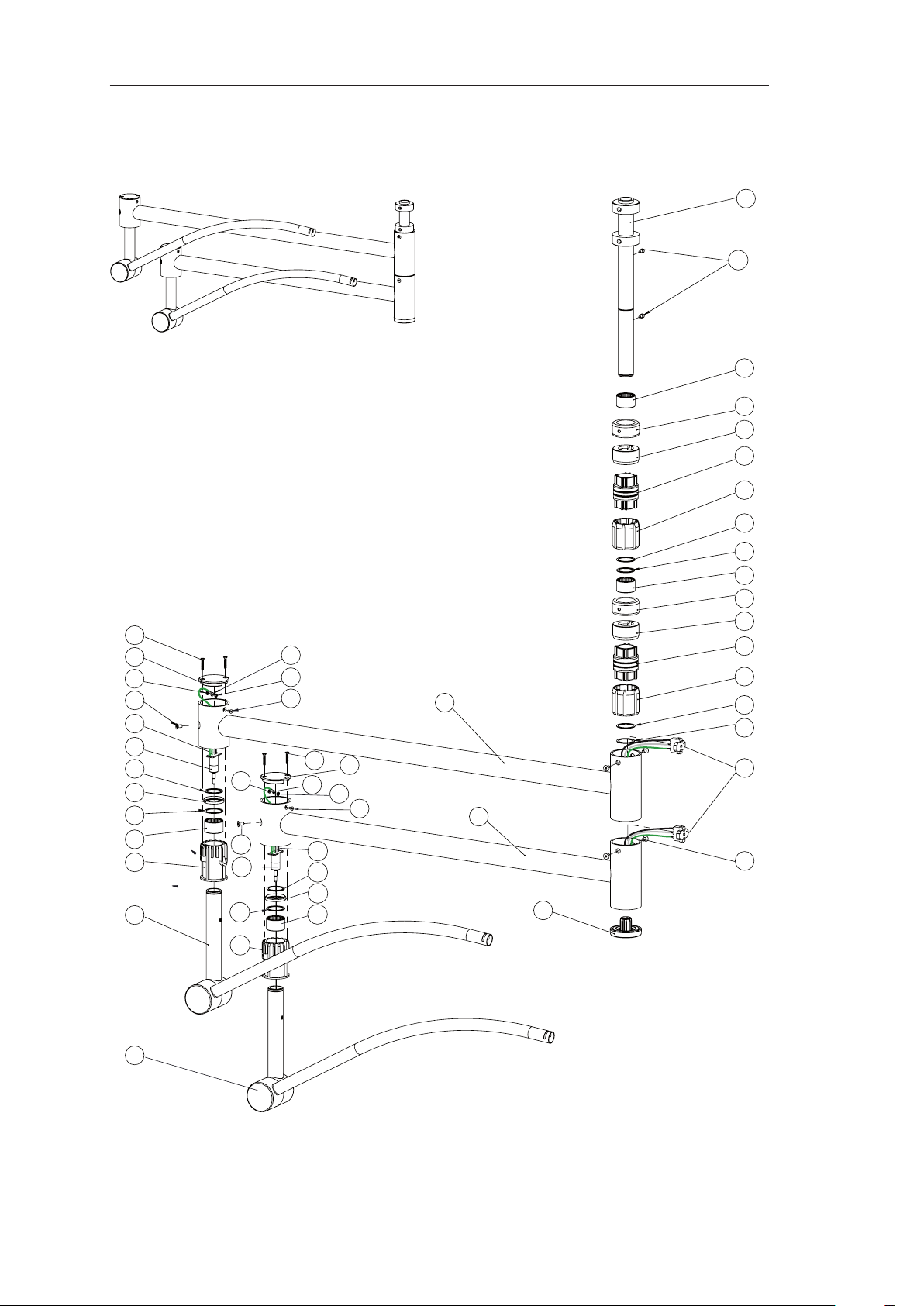
7 DIAGRAMS AND PARTS LISTS
7.1 CEILING-MOUNTED BLUELINE
Page 48

Ceiling, wall-mounted or
mobile surgical light
0136201
48
Technical manual
BLUELINE
34
33
32
31
30
35
39
28
1
2
3
4
5
6
7
8
29
22
23
24
36
25
26
9
10
11
12
13
14
15
16
17
18
27
19
2120
38
37
40
BLUE ANCHORAGE WITH POWER SUPPLY DIAGRAM 1
Page 49

Ceiling, wall-mounted or
mobile surgical light
0136201
49
Technical manual
BLUELINE
BLUE ANCHORAGE WITH POWER SUPPLY PARTS LIST 1
Ref. Part number Description Quantity
1 5 607 76 44 Anchor ring for DUO version 1
5 607 76 53 Anchor plate for single version 1
2 FHc M12 x 80 screw 6
3 5 665 20 38 M12 hex nut DIN 934-8 A4E 18
4 5 665 30 19 13 mm at washer DIN 125-ST-A4E 12
5 5 601 05 10 Sleeve 15/16x13x21 6
6 5 601 05 11 Plastic washer 30x15x7 12
7 5 608 00 05 BLUE 30/80 ange 1
8 5 608 01 33 Rail 1
3 693 05 555 BLUE 80 wall/ceiling-mounted power supply
9 6 005 30 320 CHc M3 x 20 stainless steel screw A2 NFE27161 4
10 6 023 70 032 M3 white zinc-plated washer DIN 433 8
11 5 690 03 044 Bracket for BLUE 80 MPS power supply 1
12 5 690 03 045 Plate for BLUE 80 MPS power supply 1
13 6 951 50 010 Round spacer Ø3.2 x 6 x 10 4
14 5 690 03 021 MPS 120 - 228 power supply for BLUE 80 1
15 6 951 00 555 Hexagonal spacer FF M3 x 55 4
16 5 690 03 046 Housing for BLUE 80 MPS power supply 1
17 6 005 30 310 CHc M3 x 10 stainless steel screw 5
18 5 690 11 000-10 200 mm to 1200 mm extension tube 1
19 5 690 05 609 Ceiling mounting cover, height 250 mm 2
20 5 690 10 105 BLUE 30/80 ceiling cover half-ring 2
21 CHc M3 x 25 white zinc-plated steel screw DIN 912 2
3 693 06 555 BLUE 30 wall/ceiling-mounted adjustable power supply
22 5 690 03 018 BLUE 30 wall/ceiling-mounted adjustable power supply 1
23 M5 Onduex washer 2
24 CHc M5 x 6 screw 2
25 13 mm at washer DIN 125 4
26 CHc M12 x 80 screw 2
27 M12 nylstop nut 2
28 5 665 31 02 4.3 mm star washer DIN 6797 FD-ST A4E 2
29 5 665 05 88 FHc M4 x 8 screw DIN 965-4.8 A4E 2
30 5 602 00 01 Earth terminal 1
31 6 890 10 013 Grey junction block 2
32 6 890 39 302 Blue junction block 2
33 6 89010 014 Yellow/green junction block 2
34 5 690 03 030 BLUE ange power cable 1
35 5 690 03 028 BLUE 30/80 power supply terminal strip outlet cable 1
36 5 665 30 31 12 mm Grower washer DIN 127 FD-ST A4E 6
37 5 665 07 30 M4x8 raised countersunk head screw DIN 7985 1
38 5 665 30 71 A-shape 4.3 mm star washer DIN 6797-A4E 2
39 5 600 41 29 Lighthead ange cable 1
40 5 600 44 16 Flange earth cable 1
Page 50

Ceiling, wall-mounted or
mobile surgical light
0136201
50
Technical manual
BLUELINE
30 29
27
26
25
24
28
1
22
2
3
4
5
6
7
19
20
23
21
14
15
11
12
13
16
10
8
9
1817
BLUE 30 ANCHORAGE WITHOUT POWER SUPPLY DIAGRAM 2
Page 51

Ceiling, wall-mounted or
mobile surgical light
0136201
51
Technical manual
BLUELINE
BLUE 30 ANCHORAGE WITHOUT POWER SUPPLY PARTS LIST 2
Ref. Part number Description Quantity
1 5 607 76 44 Anchor ring for DUO version 1
5 607 76 53 Anchor plate for single version 1
2 FHc M12 x 80 screw 6
3 5 665 20 38 M12 hex nut DIN 934-8 A4E 18
4 5 665 30 19 13 mm at washer DIN 125-ST-A4E 12
5 5 601 05 10 Sleeve 15/16x13x21 6
6 5 601 05 11 Plastic washer 30x15x7 12
7 5 608 00 05 BLUE 30/80 ange 1
8 5 608 01 33 Rail 1
9 5 665 31 02 4.3 mm star washer DIN 6797 FD-ST A4E 2
10 5 665 05 88 FHc M4 x 8 screw DIN 965-4.8 A4E 2
11 5 665 30 31 12 mm Grower washer DIN 127 FD-ST A4E 6
12
13 CHc M12 x 80 screw 2
14 13 mm at washer DIN 125 4
15 M12 nylstop nut 2
16 5 690 05 609 Ceiling mounting cover, height 250 mm 2
17 CHc M3 x 25 white zinc-plated steel screw DIN 912 2
18 5 690 10 105 BLUE 30/80 ceiling cover half-ring 2
19 5 665 30 71 A-shape 4.3 mm star washer DIN 6797-A4E 2
20 5 665 07 30 M4x8 DIN 7985 1
21 6 881 00 025 Diode bridge 1
22 6 590 00 014 Silicone thermal heatsink paste
23 6 005 10 516 CHc M5x16 screw 1
24 5 602 00 01 Earth terminal 1
25 6 890 10 013 Grey junction block 1
26 6 890 39 302 Blue junction block 1
27 6 89010 014 Yellow/green junction block 1
28 5 600 44 16 Earth cable 1
29 5 690 03 035 Diode bridge cable 1
30 5 600 41 29 Lighthead ange cable 1
5 690 11 000-10 200 mm to 1200 mm extension tube 1
Page 52

Ceiling, wall-mounted or
mobile surgical light
0136201
52
Technical manual
BLUELINE
1
2
3
4
5
6
22
7
19
20
23
21
10
8
9
11
12
13
16
1817
14
15
27
26
25
24
28
30 29
BLUE 80 DUO ANCHORAGE WITHOUT POWER SUPPLY DIAGRAM 3
Page 53

Ceiling, wall-mounted or
mobile surgical light
0136201
53
Technical manual
BLUELINE
BLUE 80 DUO ANCHORAGE WITHOUT POWER SUPPLY PARTS LIST 3
Ref. Part number Description Quantity
1 5 607 76 44 Anchor ring for DUO version 1
2 FHc M12 x 80 screw 6
3 5 665 20 38 M12 hex nut DIN 934-8 A4E 18
4 5 665 30 19 13 mm at washer DIN 125-ST-A4E 12
5 5 601 05 10 Sleeve 15/16x13x21 6
6 5 601 05 11 Plastic washer 30x15x7 12
7 5 608 00 05 BLUE 30/80 ange 1
8 5 608 01 33 Rail 1
9
5 665 31 02 4.3 mm star washer DIN 6797 FD-ST A4E 2
10 5 665 05 88 FHc M4 x 8 screw DIN 965-4.8 A4E 2
11 5 665 30 31 12 mm Grower washer DIN 127 FD-ST A4E 6
12 5 690 11 000-10 200 mm to 1200 mm extension tube 1
13 CHc M12 x 80 screw 2
14 13 mm at washer DIN 125 4
15 M12 nylstop nut 2
16 5 690 05 609 Ceiling mounting cover, height 250 mm 2
17 CHc M3 x 25 white zinc-plated steel screw DIN 912 2
18 5 690 10 105 BLUE 30/80 ceiling cover half-ring 2
19 5 665 30 71 A-shape 4.3 mm star washer DIN 6797-A4E 2
20 5 665 07 30 M4x8 DIN 7985 1
21 6 881 00 025 Diode bridge 1
22 6 590 00 014 Silicone thermal heatsink paste
23 6 005 10 516 CHc M5x16 screw 1
24 5 602 00 01 Earth terminal 1
25 6 890 10 013 Grey junction block 2
26 6 890 39 302 Blue junction block 2
27 6 89010 014 Yellow/green junction block 2
28 5 600 44 16 Earth cable 1
29 5 690 03 035 Diode bridge cable 2
30 5 600 41 29 Lighthead ange cable 2
Page 54

Ceiling, wall-mounted or
mobile surgical light
0136201
54
Technical manual
BLUELINE
23
29
27
26
25
24
28
1
13
2
3
4
5
6
8
10
22
12
9
19
20
11
7
15
14
21
16
18 17
BLUE LC ANCHORAGE WITHOUT POWER SUPPLY DIAGRAM 4
Page 55

Ceiling, wall-mounted or
mobile surgical light
0136201
55
Technical manual
BLUELINE
BLUE LC ANCHORAGE WITHOUT POWER SUPPLY PARTS LIST 4
Ref. Part number Description Quantity
1 5 607 76 44 Anchor ring for DUO version 1
5 607 76 53 Anchor plate for single version 1
2 FHc M12 x 80 screw 6
3 5 665 20 38 M12 hex nut DIN 934-8 A4E 18
4 5 665 30 19 13 mm at washer DIN 125-ST-A4E 12
5 5 601 05 10 Sleeve 15/16x13x21 6
6 5 601 05 11 Plastic washer 30x15x7 12
7 5 690 15 001 BLUE 30/80 LCH anchor tube 1
8 5 608 01 33 Rail 1
9 5 665 31 02 4.3 mm star washer DIN 6797 FD-ST A4E 2
10 5 665 05 88 FHc M4 x 8 screw DIN 965-4.8 A4E 2
11 5 665 30 31 12 mm Grower washer DIN 127 FD-ST A4E 6
12 5 665 30 71 A-shape 4.3 mm star washer DIN 6797-A4E 2
13 5 665 09 07 M4 nut DIN 934 A4E 2
14 6 881 00 025 Diode bridge
15 6 590 00 014 Silicone thermal heatsink paste
16 5 690 05 608 Ceiling mounting cover, height 115 mm 2
17 CHc M3 x 25 white zinc-plated steel screw DIN 912 2
18 5 690 10 105 BLUE 30/80 ceiling cover half-ring 2
19 5 665 30 71 A-shape 4.3 mm star washer DIN 6797-A4E 2
20 5 665 07 30 M4x8 DIN 7985 1
21 6 005 10 516 CHc M5x16 screw 1
22 5 665 04 70
23 5 600 41 29 Lighthead ange cable 2
24 5 602 00 01 Earth terminal 1
25 6 890 10 013 Grey junction block 2
26 6 890 39 302 Blue junction block 2
27 6 89010 014 Yellow/green junction block 2
28 5 600 44 16 Earth cable 1
29 5 690 03 035 Diode bridge cable 2
Page 56
Ceiling, wall-mounted or
mobile surgical light
0136201
56
Technical manual
BLUELINE
1
2
6
5
7
8
9
10
11
12
13
14
15
16
17
18
19
20 21 22 23 24 25 26 27 28
29
30
31
4
3
9
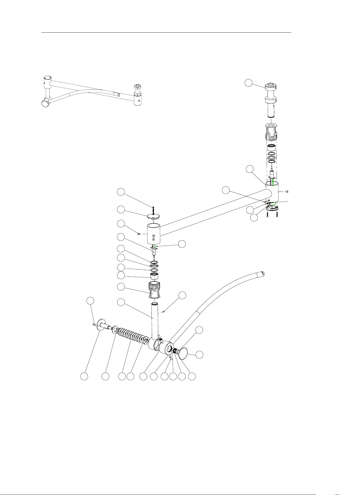
BLUE 30 SINGLE SUSPENSION ARM DIAGRAM 5
5 690 80 999
Page 57

Ceiling, wall-mounted or
mobile surgical light
0136201
57
Technical manual
BLUELINE
BLUE 30 SINGLE SUSPENSION ARM PARTS LIST 5
Ref. Part number Description Quantity
1 5 607 63 45 BLUE 30-80 single shaft 1
2 5 690 12 102 B30-80 850 mm single extension arm 1
3 Hm M4 nut 1
4 16/18 AWG M4 eyelet contact 1
5 M4 serrated washer 1
6 FHc M4 x 8 screw 1
7 FZ M4 x 25 screw 4
8 5 690 10 282 BLUE 30-80 single suspension arm cap 2
9 FHc M6 x 12 screw 4
10 5 601 64 00 ONDAL 3-way rotating contact 2
11 5 601 97 30 Circlips for 32 mm shaft 2
12 5 607 74 83 Ring 2
13 5 601 72 05 Set ring 2
14 HK 32x39x24 needle bush 2
15 5 690 10 011 Suspension shaft plastic ring 2
16 5 690 13 004 BLUE 30 spring arm interface 1
17 FHc M3 x 10 screw 1
18 FHc M5 x 16 screw 2
19 5 690 13 001 Spring arm shaft 1
20 5 665 31 78 22x30x0.5 mm washer DIN 988 A4E 2
21 5 601 97 04 40x20.4x2.25 mm spring washer DIN 2093-1.8159 14
22 5 690 13 210 BLUE 30 spring arm cam 1
23 5 690 13 004 BLUE 30 spring arm interface 1
24 5 668 00 50 NK 8/12 TN needle bearing 2
25 8M6x20 cylindrical pin 2
26 5 668 00 55 AS 1226 stop washer 1
27 5 668 0054 Axial needle bearing cage AXK 1226 1
28 5 668 00 56 LS 1226 stop washer 1
29 5 665 20 08 Nylstop nut DIN 985 A4E 1
30 5 690 10 102 BLUE 30 spring arm cap 1
31 5 690 03 039 BLUE 80/30 single 850 cable 1
Page 58

Ceiling, wall-mounted or
mobile surgical light
0136201
58
Technical manual
BLUELINE
1
15
14
13
12
11
10
9
2
3
4
5
6
7
7
8
9
10
11
12
13
14
15
16
17
BLUE 80 SINGLE SUSPENSION ARM DIAGRAM 6
5 690 81 999
Page 59

Ceiling, wall-mounted or
mobile surgical light
0136201
59
Technical manual
BLUELINE
BLUE 80 SINGLE SUSPENSION ARM PARTS LIST 6
Ref. Part number Description Quantity
1 5 607 63 45 BLUE 30-80 single shaft 1
2 5 690 12 102 B30-80 850 mm single extension arm 1
3 Hm M4 nut 1
4 16/18 AWG M4 eyelet contact 1
5 M4 serrated washer 1
6 FHc M4 x 8 screw 1
7 FZ M4 x 25 screw 4
8 5 690 10 282 BLUE 30-80 single suspension arm cap 2
9 FHc M6 x 12 screw DIN 7991 8.8 A4E 4
10 5 601 64 00 ONDAL 3-way rotating contact 2
11 5 601 97 30 Circlip for shaft Ø32 2
12 5 607 74 83 Ring 2
13 5 601 72 05 Set ring 2
14 HK 32x39x24 needle bush 2
15 5 690 10 011 Suspension shaft plastic ring 2
16 5 690 42 999 BLUE 80 spring arm 1
17 5 690 03 039 BLUE 80/30 single 850 cable 1
Page 60
Ceiling, wall-mounted or
mobile surgical light
0136201
60
Technical manual
BLUELINE
1
23
3
4
5
6
24
26
23
3
4
5
6
24
26
21
2
9
10
8
16
15
14
13
11
12
17
18
19
25
22
20
20
18
19
25
22
26
23
24
26
24
23
17
11
12
13
14
15
16
7
BLUE 30-30 DOUBLE SUSPENSION DIAGRAM 7
5 690 86 999
Page 61

Ceiling, wall-mounted or
mobile surgical light
0136201
61
Technical manual
BLUELINE
BLUE 30-30 DOUBLE SUSPENSION PARTS LIST 7
Ref. Part number Description Quantity
1 5 607 72 57 BLUE 30-80 double shaft 1
2 5 665 07 71 CHc M5x8 screw DIN 912-8.8 A4E 2
3 5 607 71 80 Needle bearing ring 4
4 5 607 73 13 BLUE 30-80 top shaft ring 2
5 5 607 73 15 Rotating contact 2
6 5 607 73 14 BLUE 30-80 bottom shaft ring 2
7 FHc M6x12 screw 4
8 5 690 10 104 Bumper 1
9 5 690 12 101 BLUE 30-80 1000 mm duo extension arm 1
10 5 690 12 100 BLUE 30-80 850 mm duo extension arm 1
11 FZ M4 x 25 screw 4
12 5 690 10 282 BLUE 30-80 single suspension arm cap 2
13 Hm M4 nut 2
14 16/18 AWG M4 eyelet contact 2
15 M4 serrated washer 2
16 FHc M4 x 8 screw 2
17 FHc M6 x 12 screw DIN 7991 8.8 A4E 4
18 5 690 03 040 BLUE 30/80 duo 1000 cable 2
19 5 601 64 00 ONDAL 3-way rotating contact 2
20 5 690 41 999 BLUE 30 wall/ceiling-mounted spring arm 2
21 5 605 31 53 3-track brushes 2
5 605 34 53 BLUE plastic ring with bearing
22 5 690 10 011 Suspension shaft plastic ring 2
23 5 668 00 39 Needle bearing bush HK 32x39x24 4
24 5 601 72 05 Set ring 4
25 5 607 74 83 Ring 2
26 5 601 97 30 Circlip for shaft Ø32 4
Page 62

Ceiling, wall-mounted or
mobile surgical light
0136201
62
Technical manual
BLUELINE
1
24
3
4
5
6
25
27
24
3
4
5
6
25
27
7
2
9
10
8
16
15
14
13
11
12
17
18
19
26
23
20
21
27
25
24
19
26
27
24
18
23
24
17
11
12
13
14
15
16
22
BLUE 30-80 DOUBLE SUSPENSION DIAGRAM 8
5 690 85 999
Page 63
Ceiling, wall-mounted or
mobile surgical light
0136201
63
Technical manual
BLUELINE
BLUE 30-80 DOUBLE SUSPENSION PARTS LIST 8
Ref. Part number Description Quantity
1 5 607 72 57 BLUE 30-80 double shaft 1
2 5 665 07 71 CHc M5x8 screw DIN 912-8.8 A4E 2
3 5 607 71 80 Needle bearing ring 4
4 5 607 73 13 BLUE 30-80 top shaft ring 2
5 5 607 73 15 Rotating contact 2
6 5 607 73 14 BLUE 30-80 bottom shaft ring 2
7 FHc M6x12 screw 4
8 5 690 10 104 Bumper 1
9 5 690 12 101 BLUE 30-80 1000 mm duo extension arm 1
10 5 690 12 100 BLUE 30-80 850 mm duo extension arm 1
11 FZ M4 x 25 screw 4
12 5 690 10 282 BLUE 30-80 single suspension arm cap 2
13 Hm M4 nut 2
14 16/18 AWG M4 eyelet contact 2
15 M4 serrated washer 2
16 FHc M4 x 8 screw 2
17 FHc M6 x 12 screw DIN 7991 8.8 A4E 4
18 5 690 03 040 BLUE 30/80 duo 1000 cable 2
19 5 601 64 00 ONDAL 3-way rotating contact 2
20 5 690 41 999 BLUE 30 wall/ceiling-mounted spring arm 1
21 5 690 42 999 BLUE 80 spring arm 1
22 5 605 31 53 3-track brushes 2
5 693 02 555 BLUE plastic ring with bearing
23 5 690 10 011 Suspension shaft plastic ring 2
24 5 668 00 39 Needle bearing bush HK 32x39x24 4
25 5 601 72 05 Set ring 4
26 5 607 74 83 Ring 2
27 5 601 97 30 Circlip for shaft Ø32 4
Page 64

Ceiling, wall-mounted or
mobile surgical light
0136201
64
Technical manual
BLUELINE
1
2
9
16
15
14
13
11
12
17
18
19
25
22
20
26
24
23
23
3
4
5
6
24
26
23
3
4
5
6
24
26
7
20
19
25
26
23
17
18
22
24
11
12
14
13
15
16
10
8
21
BLUE 80-80 DOUBLE SUSPENSION DIAGRAM 9
5 690 84 999
Page 65

Ceiling, wall-mounted or
mobile surgical light
0136201
65
Technical manual
BLUELINE
BLUE 80-80 DOUBLE SUSPENSION PARTS LIST 9
Ref. Part number Description Quantity
1 5 607 72 57 BLUE 30-80 double shaft 1
2 5 665 07 71 CHc M5x8 screw DIN 912-8.8 A4E 2
3 5 607 71 80 Needle bearing ring 4
4 5 607 73 13 BLUE 30-80 top shaft ring 2
5 5 607 73 15 Rotating contact 2
6 5 607 73 14 BLUE 30-80 bottom shaft ring 2
7 FHc M6x12 screw 4
8 5 690 10 104 Bumper 1
9 5 690 12 101 BLUE 30-80 1000 mm duo extension arm 1
10 5 690 12 100 BLUE 30-80 850 mm duo extension arm 1
11 FZ M4 x 25 screw 4
12 5 690 10 282 BLUE 30-80 single suspension arm cap 2
13 Hm M4 nut 2
14 16/18 AWG M4 eyelet contact 2
15 M4 serrated washer 2
16 FHc M4 x 8 screw 2
17 FHc M6 x 12 screw DIN 7991 8.8 A4E 4
18 5 690 03 040 BLUE 30-80 duo 1000 cable 2
19 5 601 64 00 ONDAL 3-way rotating contact 2
20 5 690 42 999 BLUE 80 spring arm 2
21 5 605 31 53 3-track brushes 2
5 693 02 555 BLUE plastic ring with bearing
22 5 690 10 011 Suspension shaft plastic ring 2
23 5 668 00 39 Needle bearing bush HK 32x39x24 4
24 5 601 72 05 Set ring 4
25 5 607 74 83 Ring 2
26 5 601 97 30 Circlip for shaft Ø32 4
Page 66

Ceiling, wall-mounted or
mobile surgical light
0136201
66
Technical manual
BLUELINE
Page 67

Ceiling, wall-mounted or
mobile surgical light
0136201
67
Technical manual
BLUELINE
7.2 WALL-MOUNTED BLUELINE
Page 68

Ceiling, wall-mounted or
mobile surgical light
0136201
68
Technical manual
BLUELINE
19
9
6
8
5
4
18
4
5
7
6
1
2
3
21
22
20
24 25 23
2726
14
15
13
12
11
16
17
10
11
12
13
7
8
15
WALL-MOUNTED BLUE 30 SUSPENSION ARM DIAGRAM 10
5 690 88 999
Page 69

Ceiling, wall-mounted or
mobile surgical light
0136201
69
Technical manual
BLUELINE
WALL-MOUNTED BLUE 30 SUSPENSION ARM PARTS LIST 10
Ref. Part number Description Quantity
1 5 608 00 16 Wall-mounted BLUE 30-80 mounting point 1
2 5 601 96 38 4-way connection strip 1
3 5 665 04 67 BZ M3 x 16 screw DIN 7985-4.8-A4E 2
5 693 02 555 BLUE plastic ring with bearing
4 5 690 10 011 Suspension shaft plastic ring 2
5 5 668 00 39 HK 32x39x24 needle bush 2
6 5 601 72 05 Set ring 2
7 5 607 74 83 Ring 2
8 5 601 97 30 Circlip for shaft Ø32 2
9 5 601 64 00 ONDAL 3-way rotating contact 1
10 5 690 12 103 B30-80 850 mm wall-mounted extension arm 1
11 FHc M6 x 12 screw DIN 7991 8.8 A4E 4
12 5 690 10 282 BLUE 30-80 single suspension arm cap 2
13 FZ M4 x 25 screw 2
14 Hm M4 nut 1
15 16/18 AWG M4 eyelet contact 2
16 M4 serrated washer 1
17 FHc M4 x 8 screw 1
18 5 690 41 999 BLUE 30 spring arm 1
19 5 690 03 038 Wiring 1
3 693 06 555 BLUE 30 wall/ceiling-mounted adjustable power supply
20 5 690 03 018 BLUE 30 wall/ceiling-mounted adjustable power supply 1
21 M5 Onduex washer 2
22 CHc M5 x 6 screw 2
23 5 690 10 106 BLUE 30-80 wall-mounting cover 1
24 M3x8 plastic screw T15 2
25 Stainless steel L4 washer 2
26 5 665 04 70 Bz M4x8 screw 1
27 5 665 30 71 A-shape 4.3 mm star washer DIN 6797-A4E 2
Page 70

Ceiling, wall-mounted or
mobile surgical light
0136201
70
Technical manual
BLUELINE
4
5
7
8
6
19
9
7
6
8
5
4
18
1
2
3
21
22
20
20
2423
11
12
13
14
15
16
17
10
13
12
11
15
WALL-MOUNTED BLUE 80 SUSPENSION ARM DIAGRAM 11
5 690 87 999
Page 71

Ceiling, wall-mounted or
mobile surgical light
0136201
71
Technical manual
BLUELINE
WALL-MOUNTED BLUE 80 SUSPENSION ARM PARTS LIST 11
Ref. Part number Description Quantity
1 5 608 00 16 Wall-mounted BLUE 30-80 mounting point 1
2 5 601 96 38 4-way connection strip 1
3 5 665 04 67 BZ M3 x 16 screw DIN 7985-4.8-A4E 2
5 693 02 555 BLUE plastic ring with bearing
4 5 690 10 011 Suspension shaft plastic ring 2
5 5 668 00 39 HK 32x39x24 needle bush 2
6 5 601 72 05 Set ring 2
7 5 607 74 83 Ring 2
8 5 601 97 30 Circlip for shaft Ø32 2
9 5 601 64 00 ONDAL 3-way rotating contact 1
10 5 690 12 103 B30-80 850 mm wall-mounted extension arm 1
11 FHc M6 x 12 screw DIN 7991 8.8 A4E 4
12 5 690 10 282 BLUE 30-80 single suspension arm cap 2
13 FZ M4 x 25 screw 2
14 Hm M4 nut 1
15 16/18 AWG M4 eyelet contact 2
16 M4 serrated washer 1
17 FHc M4 x 8 screw 1
18 5 690 42 999 BLUE 80 spring arm 1
19 5 690 03 038 Wiring 1
20 5 690 10 106 BLUE 30-80 wall-mounting cover 1
21 Stainless steel L4 washer 2
22 M3x8 plastic screw T15 2
23 5 665 04 70 Bz M4x8 screw 1
24 5 665 30 71 A-shape 4.3 mm star washer DIN 6797-A4E 3
Page 72

Ceiling, wall-mounted or
mobile surgical light
0136201
72
Technical manual
BLUELINE
4
5
7
8
6
7
6
8
5
4
18
21
22
20
1
2
3
25
23 24 2620 23
29
28
30
11
12
13
10
13
12
11
19
9
15
14
16
17
WALL-MOUNTED BLUE 30-80 SUSPENSION ARM DIAGRAM 12
WITHOUT POWER SUPPLY
5 690 94 999
Page 73

Ceiling, wall-mounted or
mobile surgical light
0136201
73
Technical manual
BLUELINE
WALL-MOUNTED BLUE 30-80 SUSPENSION ARM PARTS LIST 12
WITHOUT POWER SUPPLY
Ref. Part number Description Quantity
1 5 608 00 16 Wall-mounted BLUE 30-80 mounting point 1
2 5 601 96 38 4-way connection strip 1
3 5 665 04 67 BZ M3 x 16 screw DIN 7985-4.8-A4E 2
5 693 02 555 BLUE plastic ring with bearing
4 5 690 10 011 Suspension shaft plastic ring 2
5 5 668 00 39 HK 32x39x24 needle bush 2
6 5 601 72 05 Set ring 2
7 5 607 74 83 Ring 2
8 5 601 97 30 Circlip for shaft Ø32 2
9 5 601 64 00 ONDAL 3-way rotating contact 2
10 5 690 12 103 B30-80 850 mm wall-mounted extension arm 1
11 FHc M6 x 12 screw DIN 7991 8.8 A4E 4
12 5 690 10 282 BLUE 30-80 single suspension arm cap 2
13 FZ M4 x 25 screw 2
14 Hm M4 nut 1
15 16/18 AWG M4 eyelet contact 3
16 M4 serrated washer 1
17 FHc M4 x 8 screw 1
18 5 690 41 999 BLUE 30 spring arm 1
5 690 42 999 BLUE 80 spring arm 1
19 5 690 03 038 Wiring 1
20 5 690 10 106 BLUE 30-80 wall-mounting cover (right and left) 1
21 Stainless steel L4 washer 2
22 M3x8 T15 plastic screw 2
23 6 005 30 416 CHc M4x16 stainless steel screw 1
3 690 08 998 Diode bridge kit
24 6 881 00 025 Diode bridge 1
25 5 690 03 035 Diode bridge cable 1
26 Thermal paste
27 5 665 30 06 3.2 mm at washer DIN 125 1
28 5 665 04 70 Bz M4x8 screw 1
29 5 665 30 71 A-shape 4.3 mm star washer DIN 6797-A4E 3
Page 74
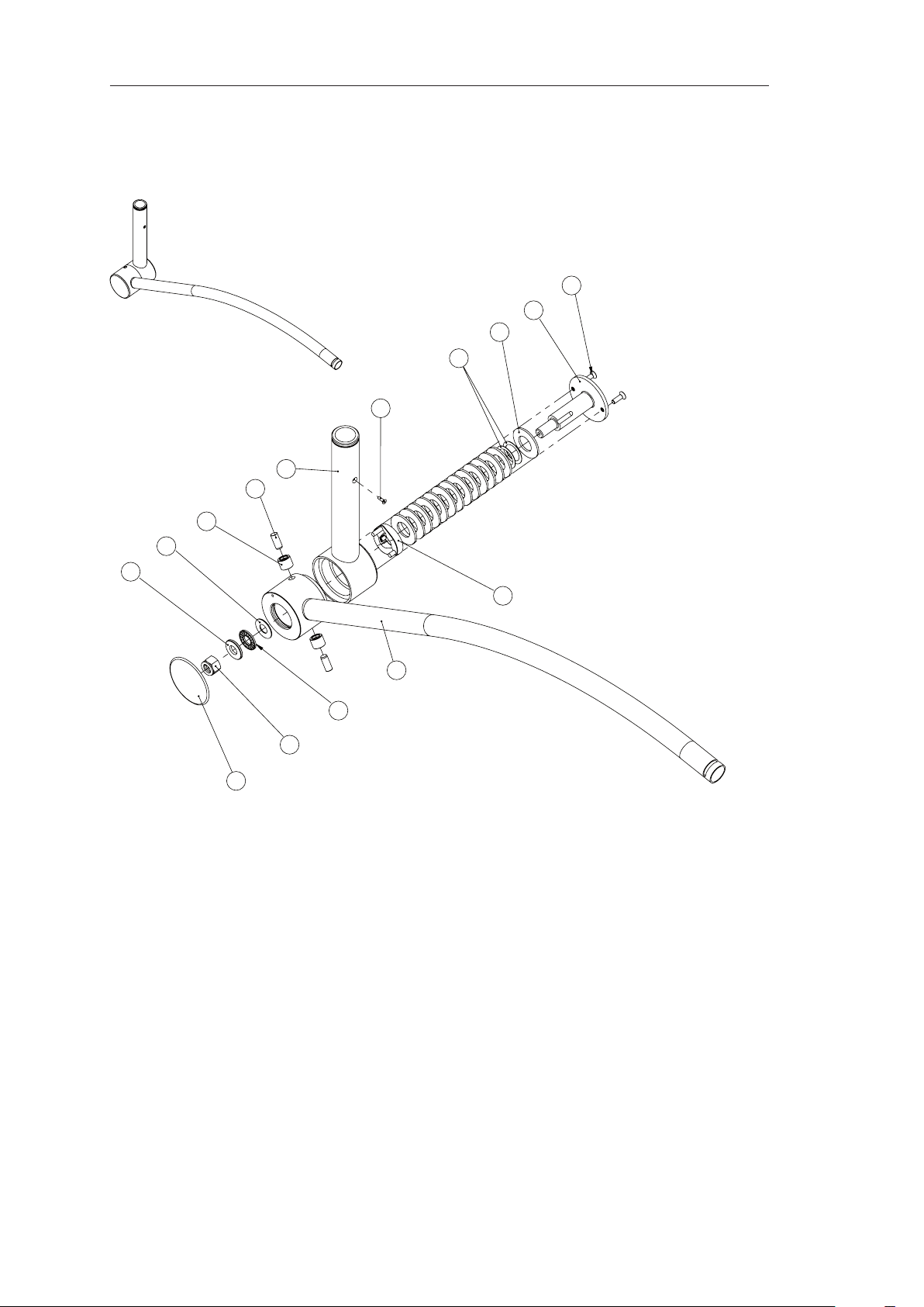
Ceiling, wall-mounted or
mobile surgical light
0136201
74
Technical manual
BLUELINE
15
1
2
3
4
5
7
8
9
11
13
14
12
10
6
BLUE 30 WALL/CEILING-MOUNTED SPRING ARM DIAGRAM 13
5 690 41 999
Page 75

Ceiling, wall-mounted or
mobile surgical light
0136201
75
Technical manual
BLUELINE
BLUE 30 WALL/CEILING-MOUNTED SPRING ARM PARTS LIST 13
Ref. Part number Description Quantity
1 FHc M5 x 16 screw 2
2 5 690 13 001 Spring arm shaft 1
3 5 601 97 04 40x20.4x2.25 mm spring washer DIN 2093-1.8159 14
4 5 665 31 78 22x30x0.5 mm washer DIN 988 A4E 2
5 FHc M3 x 10 screw 1
6 5 690 13 210 BLUE 30 spring arm cam 1
7 5 69013 004 BLUE 30 spring arm interface 1
8 8M6x20 cylindrical pin 2
9 5 668 00 50 NK 8/12 TN needle bearing 2
10 5 690 10 073 BLUE 30 spring arm painted angled tube 1
11 5 668 00 55 AS 1226 stop washer 1
12 5 668 00 54 Axial needle bearing cage AXK 1226 1
13 5 668 00 56 LS 1226 stop washer 1
14 5 665 20 08 Nylstop nut DIN 985 A4E 1
15 5 690 10 102 BLUE 30 spring arm cap 1
Page 76

Ceiling, wall-mounted or
mobile surgical light
0136201
76
Technical manual
BLUELINE
1
2
4
11
13
6
7
8
10
1
14
12
9
5
3
BLUE 80 WALL/CEILING-MOUNTED SPRING ARM DIAGRAM 14
5 690 42 999
Page 77

Ceiling, wall-mounted or
mobile surgical light
0136201
77
Technical manual
BLUELINE
BLUE 80 WALL/CEILING-MOUNTED SPRING ARM PARTS LIST 14
Ref. Part number Description Quantity
1 5 690 10 100 BLUE 80 spring arm cap 2
2 5 665 08 93 CHc M12x90 screw DIN 912-8.8 A4E 1
3 FHc M3 x 10 screw 1
4 5690 13 005 BLUE 80 spring arm interface 1
5 5 601 97 31 70 x 30.5 x 3 mm spring washer 13
6 5 607 73 55 BLUE 80 cam 1
7 5 668 00 52 NATV 10 axial guide cam roller 2
8 5 665 52 81 ISO8734 10H8x28-A-ST cam 2
9 5 690 10 071 BLUE 80 spring arm painted angled tube 1
10 5 668 00 55 AS 1226 stop washer 1
11 5 668 00 54 Axial needle bearing cage AXK 1226 1
12 5 665 02 95 Hc M6 x 30 screw DIN 913-45H A4E 2
13 5 668 00 56 LS 1226 stop washer 1
14 5 665 20 08 Nylstop nut DIN 985 A4E 1
Page 78

Ceiling, wall-mounted or
mobile surgical light
0136201
78
Technical manual
BLUELINE
Page 79

Ceiling, wall-mounted or
mobile surgical light
0136201
79
Technical manual
BLUELINE
7.3 BLUELINE MOBILE
Page 80

Ceiling, wall-mounted or
mobile surgical light
0136201
80
Technical manual
BLUELINE
1
2
6
4
3
12
7
5
13
11
8
10
9
BLUE 30 MOBILE STAND DIAGRAM 15
5 690 72 999
Page 81

Ceiling, wall-mounted or
mobile surgical light
0136201
81
Technical manual
BLUELINE
BLUE 30 MOBILE STAND PARTS LIST 15
Ref. Part number Description Quantity
1 M4 x 8 CHc screw DIN 7984 1
2 5 690 14 023 BLUE 30 MOBILE stand tube 1
3 5 690 14 025 Plastic star section 1
4 5 690 14 022 BLUE 30 short stand section 3
5 5 690 14 021 BLUE 30 long stand section 2
6 5 690 14 024 BLUE 30 cap 5
7 5 605 17 83 50-ZIO x 35.5 caster 3
8 5 605 17 82 50-ZIO x 35.5 caster with brake (set of 2) 2
5 605 17 84 Assembly kit for 3/5 legs
9 M8 x 35 CHc screw DIN 912 5
10 8.4 mm star washer DIN 6797 6
11 M8 x 22 CHc screw DIN 912 1
12 M8 nut DIN 934 5
13 5 690 14 026 BLUE 30 stand star section 1
Page 82

Ceiling, wall-mounted or
mobile surgical light
0136201
82
Technical manual
BLUELINE
7
10
12
1
2
4
3
9
8
6
5
14
11
13
15
16
17
BLUE 30 MOBILE SPRING ARM DIAGRAM 16
5 690 40 999
Page 83

Ceiling, wall-mounted or
mobile surgical light
0136201
83
Technical manual
BLUELINE
BLUE 30 MOBILE SPRING ARM PARTS LIST 16
Ref. Part number Description Quantity
1 FHc M5 x 16 screw 2
2 5 690 13 001 Spring arm shaft 1
3 5 601 97 04 40x20.4x2.25 mm spring washer DIN 2093-1.8159 14
4 5 665 31 78 22x30x0.5 mm washer DIN 988 A4E 2
5 5 690 10 102 BLUE 30 spring arm cap 1
6 5 690 13 210 BLUE 30 spring arm cam 1
7 5 690 14 003 BLUE 30 MOBILE spring arm vertical tube 1
8 8M6x20 cylindrical pin 2
9 5 668 00 50 NK 8/12 TN needle bearing 2
10 5 690 10 073 BLUE 30 spring arm painted angled tube 1
11 5 668 00 55 AS 1226 stop washer 1
12 5 668 00 54 Axial needle bearing cage AXK 1226 1
13 5 668 00 56 LS 1226 stop washer 1
14 5 665 20 08 Nylstop nut DIN 985 A4E 1
15 5 690 10 103 BLUE 30 MOBILE spring arm complete power supply cover 1
3 693 07 555 BLUE 30 MOBILE adjustable power supply (RAL Europe)
16 5 690 03 017 BLUE 30 MOBILE adjustable power supply (RAL Europe) 1
3 693 08 555 BLUE 30 MOBILE adjustable power supply (US)
16 5 690 03 019 BLUE 30 MOBILE adjustable power supply (US) 1
17 5 600 44 82 Wiring 1
Page 84

Ceiling, wall-mounted or
mobile surgical light
0136201
84
Technical manual
BLUELINE
5
8
21
9
7
320
1762224 54
1
2
3
5
25
11 10
13
19
26
27
15
14
24
18
12
23
16
BLUE 80 MOBILE STAND DIAGRAM 17
5 690 75 999
Page 85

Ceiling, wall-mounted or
mobile surgical light
0136201
85
Technical manual
BLUELINE
BLUE 80 MOBILE STAND PARTS LIST 17
Ref. Part number Description Quantity
1 5 690 14 000 BLUE 80 MOBILE stand straight tube 1
2 5 690 14 001 BLUE 80 MOBILE ve-legged stand 1
3 5 690 14 032 BLUE 80 MOBILE transformer unit 1
4 5 690 14 031 power supply bracket 1
5 5 665 07 33 M3 x 8 screw DIN 966 - EN ISO 7047 8
6 6 951 10 310 M3 x 10 stainless steel cylindrical spacer 4
7 5 690 03 021 MPS 120-228 power supply 1
8 5 665 30 06 3.2 mm A-shape at washer DIN 125 4
9 6 005 30 306 CHc M3 x 6 A2 stainless steel screw 4
10 5 665 07 62 Low-prole CHc M5x10 screw DIN 6912-8.8-A4E 3
11 5 665 30 75 5.3 mm A-shape star washer DIN 6797-A4E 10
12 5 601 42 47 BLUE 80 75 mm caster 3
13 6 060 12 525 Flat anti-static caster 0443-01A 2
14 5 690 14 005 BLUE 80 MOBILE spring arm vertical tube 1
15 5 665 08 23 Low-prole CHc M5 x 8 screw with guide hole DIN 7984 A2 1
16 5 600 44 88 BLUE stand cable 1
3 690 10 997 BLUE 80 MOBILE mains cable loom S/A
17 5 690 03 031 Wiring 1
18 6 914 00 095 KEC mains connector (BLUE 30/80) 1
19 6 890 04 520 2-pole fuse drawer without mains cut-out 1
20 5 601 89 21 Sleeve 1
3 690 57 555 Set of 10 5x20 3.15 A quick-blow fuses
21 6 936 00 020 5x20 3.15 A quick-blow fuse 2
3 690 11 997 BLUE 80 MOBILE power supply cable outlet loom
22 6 887 00 02 Ferrite 1
23 5 690 03 029 BLUE 80 power supply cable outlet 1
24 5 690 03 050 Earth cable 2
25 6 013 90 525 Hm M5 stainless steel nut A2 NF E27 411 2
26 5 607 52 05 Mains cable (Europe)
27 5 607 52 03 Mains cable (US)
Page 86

Ceiling, wall-mounted or
mobile surgical light
0136201
86
Technical manual
BLUELINE
Page 87

Ceiling, wall-mounted or
mobile surgical light
0136201
87
Technical manual
BLUELINE
7.4 BLUELINE HOSPITAL
Page 88

Ceiling, wall-mounted or
mobile surgical light
0136201
88
Technical manual
BLUELINE
32
1
31
29
28
30
15
16
13
14
3
8
7
9
10
11
13
22
12
18
2 465
21
20 19 17 23
38
9
24 25 26 27
35
33
34
2221
9
36
37
10
7
41
39
40
BLUE 30 HOSPITAL DIAGRAM 18
5 690 77 999
Two-way switch:
BLUE 30 HOSPITAL position
Page 89

Ceiling, wall-mounted or
mobile surgical light
0136201
89
Technical manual
BLUELINE
BLUE 30 HOSPITAL PARTS LIST 18
Ref. Part number Description Quantity
1 5 69 14 027 BLUE 30 HOSPITAL stand tube 1
2 5 690 14 008 BLUE hospital label 1
3 5 690 10 075 BLUE 30 MOBILE transformer unit 1
4 5 601 89 21 Sleeve 1
5 6 914 00 95 Mains connector 1
6 M3 x 20 solder stud 4
7 5 690 03 022 BLUE 30/80 charger board 1
8 5 601 97 21 7 x 3.6 x 12 mm spacer 4
9 5 665 30 06 3.2 mm A-shape at washer DIN 125 8
10 5 665 20 21 Nut DIN 934-5-A4E 4
11 6 887 00 02 Ferrite 1
12 5 607 78 97 Battery 2
13 6 013 20 432 Hu M4 stainless steel nut A2 DIN 934 5
14 5 665 30 71 A-shape 4.3 mm star washer DIN 6797-A4E 6
15 CEMBRE eyelet UL RP-M4 2
16 M4 x 10 solder stud 5
17 6 005 30 306 CHc M3 x 6 A2 stainless steel screw 4
18 5 690 14 200 BLUE 30 HOSPITAL light stand 1
19 5 690 03 042 MPS 120-15 power supply for BLUE hospital 1
20 5 951 10 310 M3 x 10 stainless steel cylindrical spacer 4
21 5 690 10 092 BLUE 30 HOSPITAL power supply bracket 1
22 5 665 07 33 M3 x 8 screw DIN 966 - EN ISO 7047 12
23 5 690 10 086 BLUE 30 hospital transformer unit grille 1
24 5 665 09 19 CHc M6 x 40 screw DIN 912-8.8 A4E 2
25 5 665 30 13 6.4 mm at washer DIN 125-ST-B2E 3
26 5 665 30 77 6.4 mm star washer DIN 6797 FD-ST A4E 2
27 5 665 20 32 M6 nut DIN 6-934-A5E 3
28 5 690 03 031 BLUE charger mains power supply cable 1
29 5 690 03 049 BLUE 30 HOSPITAL charger board cable 1
30 5 600 43 69 Earth cable 1
31 5 690 03 027 BLUE 30 battery charger cable 1
32 5 690 03 036 BLUE 30 power supply charger cable outlet 1
33 6 890 04 520 2-pole fuse drawer without mains cut-out 1
3 690 57 555 Set of 10 5x20 3.15 A quick-blow fuses 1
34 6 936 00 020 5x20 3.15 A quick-blow fuse 2
35 5 665 05 24 Pan head cross-head M3 x 10 screw DIN 7985-4.8-A4E 2
36 5 601 97 75 Bush 2
37 5 665 30 66 3.2 mm star washer DIN 6797-A4E 2
38 5 601 97 74 White mounting ring 2
39 5 607 52 05 Mains cable (Europe) 1
40 5 607 52 03 Mains cable (US) 1
3 693 01 555 Pack of 10 miniature 7.5 A 32 V quick-blow fuses 1
41 6 936 00 050 Miniature 7.5 A 32 V quick-blow fuse 1
Page 90

Ceiling, wall-mounted or
mobile surgical light
0136201
90
Technical manual
BLUELINE
13
1
2
3
4
5
7
8
6
11
12
9
10
BLUE 30 HOSPITAL STAND DIAGRAM 19
5 690 14 200
Page 91

Ceiling, wall-mounted or
mobile surgical light
0136201
91
Technical manual
BLUELINE
BLUE 30 HOSPITAL STAND PARTS LIST 19
Ref. Part number Description Quantity
1 M4 x 8 CHc screw DIN 7984 1
2 5 690 14 027 BLUE 30 HOSPITAL stand tube 1
4 5 690 14 025 Plastic star section 1
5 M8 nut DIN 934 5
6 5 690 14 022 BLUE 30 short stand section 3
7 5 690 14 021 BLUE 30 long stand section 2
8 5 690 14 024 BLUE 30 cap 5
5 605 17 84 Assembly kit for 8/5 legs
9 5 690 14 026 BLUE 30 stand star section 1
10 8.4 mm star washer DIN 6797 6
11 M8 x 35 CHc screw DIN 912 5
3 M8 x 22 CHc screw DIN 912 1
12 5 605 17 83 50-ZIO x 35.5 caster 3
13 5 605 17 82 50-ZIO x 35.5 caster with brake 2
Page 92

Ceiling, wall-mounted or
mobile surgical light
0136201
92
Technical manual
BLUELINE
32
31
33
28
29
27
1
30
2
3
6
8
7
10
11
39
22
25
23
18
9
12
36
38
37
3534
5
16
15
14
13
4
17
9
19
20
21
26
24
42
7
43
44
24
13
14
15
42
41
40
BLUE 80 HOSPITAL STAND DIAGRAM 20
5 690 76 999
Two-way switch:
BLUE 80 HOSPITAL position
Page 93

Ceiling, wall-mounted or
mobile surgical light
0136201
93
Technical manual
BLUELINE
BLUE 80 HOSPITAL STAND PARTS LIST 20
Ref. Part number Description Quantity
1 5 69 10 070 BLUE 80 HOSPITAL stand straight tube 1
2 5 690 14 008 BLUE hospital label 1
3 5 690 10 072 BLUE 80 MOBILE transformer unit 1
4 5 601 89 21 Sleeve 1
5 6 914 00 95 Mains connector 1
6 M3 x 20 solder stud 4
7 5 690 03 022 BLUE 30/80 charger board 1
8 5 601 97 21 7 x 3.6 x 12 mm spacer 4
9 5 665 30 06 3.2 mm A-shape at washer DIN 125 8
10 5 665 20 21 Nut DIN 934-5-A4E 4
11 5 665 30 77 A-shape 6.4 mm star washer DIN 6797 FD-ST A4E 6
12 5 665 02 82 CHc M6 x 40 screw DIN 912-8.8 A4E 6
13 6 013 20 432 Hu M4 stainless steel nut A2 DIN 934 3
14 5 665 30 71 A-shape 4.3 mm star washer DIN 6797-A4E 6
15 5.3 mm eyelet UL 3
16 M4 x 10 solder stud 3
17 6 005 30 306 CHc M3 x 6 A2 stainless steel screw 4
18 5 690 14 001 BLUE 80 MOBILE ve-legged stand 1
19 5 690 03 042 MPS 120-15 power supply for BLUE hospital 1
20 5 951 10 310 M3 x 10 stainless steel cylindrical spacer 4
21 5 690 14 031 power supply bracket 1
22 5 665 07 62 Low-prole CHc M5x10 screw DIN 6912-8.8-A4E 2
23 5 665 30 75 A-shape 5.3 mm star washer DIN 6797-A4E 2
24 5 665 07 33 M3 x 8 screw DIN 966 - EN ISO 7047 12
25 5 606 77 42 AMP 9041 S12V-45Ah battery 2
26 5 690 10 082 BLUE 80 hospital transformer unit grille 1
27 5 690 03 026 BLUE 80 battery charger cable
28 6 060 12 525 Flat anti-static caster 0443-01A 2
29 5 601 42 47 BLUE 80 75 mm caster 3
30 6 887 00 02 Ferrite 1
31 5 690 03 032 BLUE 80 power supply cable outlet 1
32 5 690 03 036 BLUE power supply charger cable outlet 1
3 690 10 997 BLUE 80 mains cable loom S/A
33 5 690 03 031 BLUE charger mains power supply cable 1
34 6 890 04 520 2-pole fuse drawer without mains cut-out 1
3 690 57 555 Set of 10 5x20 3.15 A quick-blow fuses
35 6 936 00 020 5x20 3.15 A quick-blow fuse 2
36 5 601 6289 Rubber bush 2
37 5 665 30 08 4.3 mm at washer DIN 125-ST A4E 2
38 5 665 07 50 M4 x 12 Z-type cross-head screw DIN 7985 2
39 5 607 58 31 Captive nut 2
40 5 601 81 90 Ring 1
41 5 665 08 23 CHc low-prole M5 x 8 screw DIN 7984 A2 1
42 5 600 43 69 Earth cable 1
43 5 607 52 05 Mains cable (Europe) 1
44 5 607 52 03 Mains cable (US) 1
6 936 00 050 Pack of 10 miniature 7.5 A 32 V quick-blow fuses
45 6 936 00 050 Miniature 7.5A 32V quick-blow fuse
Page 94

Ceiling, wall-mounted or
mobile surgical light
0136201
94
Technical manual
BLUELINE
14
7
12
10
13
11
1
2
4
3
9
8
6
5
15
BLUE 30 HOSPITAL SPRING ARM DIAGRAM 21
5 690 44 999
Page 95

Ceiling, wall-mounted or
mobile surgical light
0136201
95
Technical manual
BLUELINE
BLUE 30 HOSPITAL SPRING ARM PARTS LIST 21
Ref. Part number Description Quantity
1 FHc M5 x 16 screw 2
2 5 690 13 001 Spring arm shaft 1
3 5 601 97 04 40x20.4x2.25 mm spring washer DIN 2093-1.8159 14
4 5 665 31 78 22x30x0.5 mm washer DIN 988 A4E 2
5 5 690 10 102 BLUE 30 spring arm cap 1
6 5 690 13 210 BLUE 30 spring arm cam 1
7 5 690 10 074 BLUE 30 spring arm vertical tube 1
8 8M6x20 cylindrical pin 2
9 5 668 00 50 NK 8/12 TN needle bearing 2
10 5 690 10 073 BLUE 30 spring arm painted angled tube 1
11 5 668 00 55 AS 1226 stop washer 1
12 5 668 00 54 Axial needle bearing cage AXK 1226 1
13 5 668 00 56 LS 1226 stop washer 1
14 5 665 20 08 Nylstop nut DIN 985 A4E 1
15 5 690 03 048 Spring arm ergodisc cable
Page 96

Ceiling, wall-mounted or
mobile surgical light
0136201
96
Technical manual
BLUELINE
3
11
10
13
12
8
7
1
9
6
5
4
2
1
BLUE 80 MOBILE/HOSPITAL SPRING ARM DIAGRAM 22
5 690 43 999
Page 97
Ceiling, wall-mounted or
mobile surgical light
0136201
97
Technical manual
BLUELINE
BLUE 80 MOBILE/HOSPITAL SPRING ARM PARTS LIST 22
Ref. Part number Description Quantity
1 5 690 10 100 BLUE 80 spring arm cap 2
2 5 665 08 93 CHc M12x90 screw DIN 912-8.8 A4E 1
3 5 665 20 08 Nylstop nut DIN 985 A4E 1
4 5690 14 004 BLUE 80 MOBILE spring arm interface 1
5 5 601 97 31 70 x 30.5 x 3 mm spring washer 13
6 5 607 73 55 BLUE 80 cam 1
7 5 668 00 52 NATV 10 axial guide cam roller 2
8 5 665 52 81 10H8x28-A-ST cam ISO 8734 2
9 5 690 10 071 BLUE 80 spring arm painted angled tube 1
10 5 668 00 55 AS 1226 stop washer 1
11 5 668 00 541 Axial needle bearing cage AXK 1226 1
12 5 665 02 95 Hc M6 x 30 screw DIN 913-45H A4E 2
13 5 668 00 56 LS 1226 stop washer 1
Page 98

Ceiling, wall-mounted or
mobile surgical light
0136201
98
Technical manual
BLUELINE
Page 99

Ceiling, wall-mounted or
mobile surgical light
0136201
99
Technical manual
BLUELINE
7.5 LIGHTHEADS
Page 100

Ceiling, wall-mounted or
mobile surgical light
0136201
100
Technical manual
BLUELINE
14
20 19 21
23
24
15
16
17
18
22
4
28
16
26
27
25
3
5
9
11
12
10
8
1
2
29
6
7
13
30
31
BLUE 30 LIGHTHEAD DIAGRAM 23
5 690 50 999
 Loading...