

Page 1

111801 / 02 / 03
Betaclassic / Alphaclassic
Maintenance and Mobile O.R. table
Repair Instructions
English
MAQUET GmbH + Co. KG · Postfach 2162 · D-76411 Rastatt
Telefon (07222) 932-0 ·
1118.0XGB_06
06.2005
Page 2

Wartungs- und Reparaturanleitung Alphaclassic / Betaclassic
Maintenance and Repair Instruction
1118
1118.0XGB_ 06 Page: 1
Page 3

Wartungs- und Reparaturanleitung Alphaclassic / Betaclassic
Maintenance and Repair Instruction
1118
Contents: Page:
General 3
1. Design and functional description 5
Summary of functional parts 5
Transformer, charging unit (1118.02 / 03) 5
Batteries (1118.02 /03) 5
Controller unit A1 and IR-receiver board A4 (1118.03) 6
Corded hand control (1118.03) 6
Override board A2 (1118.03) 6
IR-remote control (1118.03) 6
2. Measurements and tests - electrical, electronic (1118.02) 8
2.1 Transformer T1 primary 8
2.2 Transformer T1 secondary 8
2.3 Charging unit 8
2.4 Batteries 8
2.5 Electric motor 8
3. Measurements and tests - hydraulic 10
3.1 Check of the oil level 10
3.2 System pressure 10
3.3 Hydraulic cylinders 10
3.4 Lowering valve (general), Lowering valve of 1118.01 / 02 12
double check valve (1118.03) 14
3.5 Potentiometer for “0“-positioning (1118.03) 14
3.6 Corded hand control (1118.03) 15
3.7 IR-remote control (1118.03) 15
4. Identification of faults – what to do if... - 16
5. Repair work / instructions for replacement of components 18
5.1 Casings (of the column, of the base- , bellows) 18
5.2 Guiding 20
5.3 Castors with locking lever 22
5.4 Pedal pump (1118.01 / 02) 24
5.5 6/3 directional valve with switch tray (1118.01 / 02) 26
5.6 Lowering valve (1118.01 / 02) 28
5.7 Lowering valve (1118.01 / 02) 30
Double check valve, 5/3-directional valve (1118.03) 30
5.8 Hydraulic cylinders (Height, tilting, trendelenburg) 32
5.9 Hydraulic power unit (1118.02 / 03) 34
5.10 Charging unit, Batteries (1118.02) 36
Charging unit, Batteries (1118.03) 38
5.11 Gas spring (back and leg plate) 40
5.12 Longitudinal shift – Bowden cable ( Type „J“, „K“) 42
5.13 Longitudinal shift – Linear guide ( Type „J“, „K“) 44
5.14 Replacement of gear parts (Spindle, cog wheels) of body elevator (Type „G“, „H“) 46
5.15 Controller unit A1 and IR-Receiver board A4 (1118.03) 50
5.16 Adjustment/setting of the “0“- positioning potentiometer (1118.03) 52
1118.0XGB_ 06 Page: 2
Page 4

Wartungs- und Reparaturanleitung Alphaclassic / Betaclassic
Maintenance and Repair Instruction
1118
General
MAQUET products are to be serviced annually (assuming between 200 and 300 hours in service each year).
Damaged and/or defective components can be replaced by following the instructions given in this manual.
Special tools and equipment will be required for certain repairs.
Maintenance and repair may be carried out only by MAQUET GmbH & Co KG or by
service personnel licensed and authorized by MAQUET to do so.
1118.0XGB_ 06 Page: 3
Page 5

Wartungs- und Reparaturanleitung Alphaclassic / Betaclassic
Maintenance and Repair Instruction
1118
1
3
2
1118.0XGB_ 06 Page: 4
Page 6
Wartungs- und Reparaturanleitung Alphaclassic / Betaclassic
Maintenance and Repair Instruction
1118
1. Design and functional description
The main components:
- Transformer (1118.02/03)
- Charging unit, Batteries (1118.02/03)
- DC motor (1118.02/03)
- Hydraulic pump (1118.02/03)
- Pedal pump
- 6/3 directional valve with selector calotte
- Lowering valve
- Hydraulic pressure lines, hydraulic cylinders
- Lowering valve (check valve)
For further information refer to the technical description and to the operating instructions
Description
1118 is a mobile O.R. table that is also available as a electrical-hydraulic version. Actuation of its hydraulic
cylinders is selected by means of a selector calotte.
A 6/3-channel valve (1) [6 connections, 3 switch positions] is used to control the oil flow. Channels are switched
depending on the position of the selector calotte to either extend or reverse the piston rod of the selected cylinder.
2 combined switch&check valves (2) are assigned to the 6/3-channel valves of the tilting and the
trendelenburg functions. Channels of these combined switch&check valves are opened or closed by means of the
oil flow coming from the 6/3-channel valve.
2 lowering valves (check valves) (2) for tilting and trendelenburg belong to the 6/3 directional valve that are
controlled i.e. opened or closed, by means of the oil flow of the 6/3 directional valve.
The A and B channels of these lowering valves are closed in quiescent position in order to prevent the piston rod
from being pushed back under load.
Depending on the position of the selector calotte the functions “tilting” and “trendelenburg” are actuated.
In neutral position of the selector calotte the height cylinder is selected. Contrary to the tilting and trendelenburg
cylinder, the height cylinder is a single-acting type
To move the table downward the lowering valve (3) must be actuated by means of the separate pedal lever.
- see also the description in the operating instructions.
Transformer and charging unit – only types with electrical option (1118.02)
The O.R. table is supplied with the mains voltage via a 2-conductor cord with a standard inlet-plug and a mains
plug. The transformer is equipped with a voltage selector to adapt the O.R. table correctly to the on-site voltage
(100...240 V). The primary winding consists of four parts – 2x10⁴ V and 2x12V.
To select a voltage of e.g. 230V, all four parts of the winding are connected in series (=232V).
The lower limit of voltages that can be selected is achieved in that both the 104V-windings are connected parallel.
A temperature fuse (133°C) is integrated in the primary winding. This fuse cannot be replaced i.e. the complete
transformer must be replaced if this fuse has blown.
The secondary windings provide 2x14V as a supply voltage for the charger board A3.
The 2 batteries and the 24V-DC-motor are connected to the charger board A3. These 2 parts are located in the
base of the O.R. table.
The AC voltages (2x24V) from the transformer are used to produce 2 charging voltages of 13.75V that are
regulated separately. Each of these voltages is connected to one battery.
Batterien (1118.02/03)
The batteries used for this O.R. table are maintenance-free lead-gel types. These batteries supply the motor with
24V DC, . 2 batteries with are capacity of 7Ah are sufficient for 1118.02 – batteries with a capacity of 15Ah are
used for 1118.03. The period for which the O.R. table can be operated by the batteries depends on the power
consumption of the motor and the time for which the motor is actually running. The nominal current consumption
of the motor is app. 7A.
According to the supplier, the useful lifetime of the batteries is 5-6 years.
This is equivalent to 300 cycles of charging/discharging when the batteries are charged weekly.
1118.0XGB_ 06 Page: 5
Page 7

Wartungs- und Reparaturanleitung Alphaclassic / Betaclassic
Maintenance and Repair Instruction
1118
Controller unit A1 and IR- receiver board A4 (type 1118.03 only)
The controller unit A1 is located underneath the black bellows and is covered by a metal protection plate.
The IR receiver board is plugged onto the controller unit A4 as an additional board.
Both IR preamplifiers B1 and B2 are connected to this board.
nd
One of the preamplifiers is located at the head side, the 2
one at the foot side of the column. The receiver board
A4 and the preamplifiers B1/B2 are permanently supplied with a voltage of 5V. Current consumption is very low
i.e. this affects the battery capacity only negligibly.
If more than one O.R. table with IR remote control is used in a surgical department (same floor) each of these
tables and the correspondig remote control must be set to its individual code – see technical description.
2 potentiometers B3/B4 for the “0” positioning and one potentiometer B7 for the height adjustment are connected
to the controller unit A1. Their positions are monitored by the controller unit and functions are carried out
accordingly.
Output voltages of the potentiometers must always be in the range of 0,16V...4,84V.
Corded hand control (type 1118.03 only)
The corded handcontrol consists of 2 housing parts, a PCB with pushbuttons for the functions and an LED for
status indication,
a keypad foil, and a spiral cable with 4 wires (B5, 5V, 0V, Data).
Voltage for the internal circuit is supplied by the connectors 0V
and 5V. B% is used to switch the controller unit A4 ON and OFF.
The line “DATA” is used for bi-directional communication between hand control and controller unit.
Serial signals are sent by the hand control to actuate functions accordingly. The controller unit sends information
to the hand control to actuate the status LEDs accordingly.
To switch the system on, the button “ON” must be pressed.
The status LEDs “battery, mains, ON” are actuated briefly.
After this sequence only the LEDs that indicate the situation
of the O.R. table will be illuminated.
The individual function buttons can now be actuated.
If no function is actuated for a period of 4 min. the controller
unit will be switched off automatically.
Override A2 (type 1118.03 only)
The functions of the override panel correspond to the
functions of the corded hand control. The override panel
can be used as an emergency control if functions of the hand control or the controller unit A4 fail.
Contrary to the hand control the override panel directly
actuates the valve of the desired function. The motor can
directly be actuated by means of the button “ON”, i.e. 2 buttons must be pressed simultaneously – “ON” + the
function button for the movement.
IR remote control (type 1118.03 only)
Contrary to the corded hand control there is no bi-directional
communication with the controller unit.
The LED “battery” indicates the capacity status of the accumulator inside the remote control.
Information on the capacity of the accumulators of the O.R. table is given at the override board.
If no function is actuated within a period of 1,5 min. the controller
Unit will be switched off automatically.
1118.0XGB_ 06 Page: 6
Page 8

Wartungs- und Reparaturanleitung Alphaclassic / Betaclassic
Maintenance and Repair Instruction
1118
5
BK
A
RD
Charger unit (0970.2083)
1118
22.5
3
1118.0XGB_ 06 Page: 7
Page 9

Wartungs- und Reparaturanleitung Alphaclassic / Betaclassic
Maintenance and Repair Instruction
1118
2. Measurements and tests - electrical, electronic
2.1
Measurements at the primary part (1) - transformer T1:
Voltage as per the selector position and the actual mains voltage.
2.2
Measurements at the primary part (2) - transformer T1
2 x 14 ... 15 Volt AC at the plug connectors of the transformer
2 LEDs at the display A§ must be illuminated.
2.3
Charging unit (3):
Connect the O.R. table to the mains supply.
Measure the voltage at the batteries.
Voltage ⇒ in the range of 13,6 V ... 13,95 V DC
Otherwise the charger board must be replaced.
Charging current:
The current from the charger board to the batteries depends on the condition of the batteries i.e.
information on the condition of the charging unit cannot be obtained from the charging current.
Batteries (5):
Test by means of connecting a light bulb (12 V ca. 45 Watt)
Battery in good condition
Weak battery
To be sure about the test result, a weak battery should be charged and tested again.
Both batteries should always be replaced together.
2.5
Test of motor M1
Disconnect the plug X3.1 from the charging unit (3), connect an Ampere-meter in between and select
a function. Fully press the pump lever and let the cylinder move to its final position. (Max. pressure: 90
bar)
The current consumption must be in the range of 6 ... 7,5 A..
If the current consumption is higher than 8 A
defective.
Remove the motor and measure the current consumption with no mechanical load.
Motor running without load:
If the current is higher than 0,6 A, replace the motor. If the motor is not found to bedefective →
Replace the hydraulic pump.
After replacement of the pump, check the current consumption (< 8 A).
Please note:
Use of an O.R. table with excessive current consumption for a longer period may entail a failure of the
charging unit (3) and other components..
:⇒ bright light for 1...2 min. (good charge/capacity)
:⇒ Light becomes visibly darker after app. 1 min. Voltage drops below 10 V.
, the motor (7) or the hydraulic pump (8) is probably
current max 0,6 Amp.
1118.0XGB_ 06 Page: 8
Page 10
Wartungs- und Reparaturanleitung Alphaclassic / Betaclassic
Maintenance and Repair Instruction
90 bar 1118.01/02
100 bar 1118.03
1118
4
3.1
3.2
1118.01 / 02
1118.03
3.3
1118.0XGB_ 06 Page: 9
Page 11

Wartungs- und Reparaturanleitung Alphaclassic / Betaclassic
Maintenance and Repair Instruction
1118
3. Measurements and tests - hydraulic
Please note:
Before a hydraulic line is opened the concerned cylinder must be free from mechanical load i.e. it must
be prevented from sinking down. Move the piston rod to a position in which it is free from load. In most
cases this will be the lowermost position of the table movement.
For the height cylinder a distance bar must be used to support the table and prevent it from sinking
down. This will also avoid loss of much hydraulic fluid.
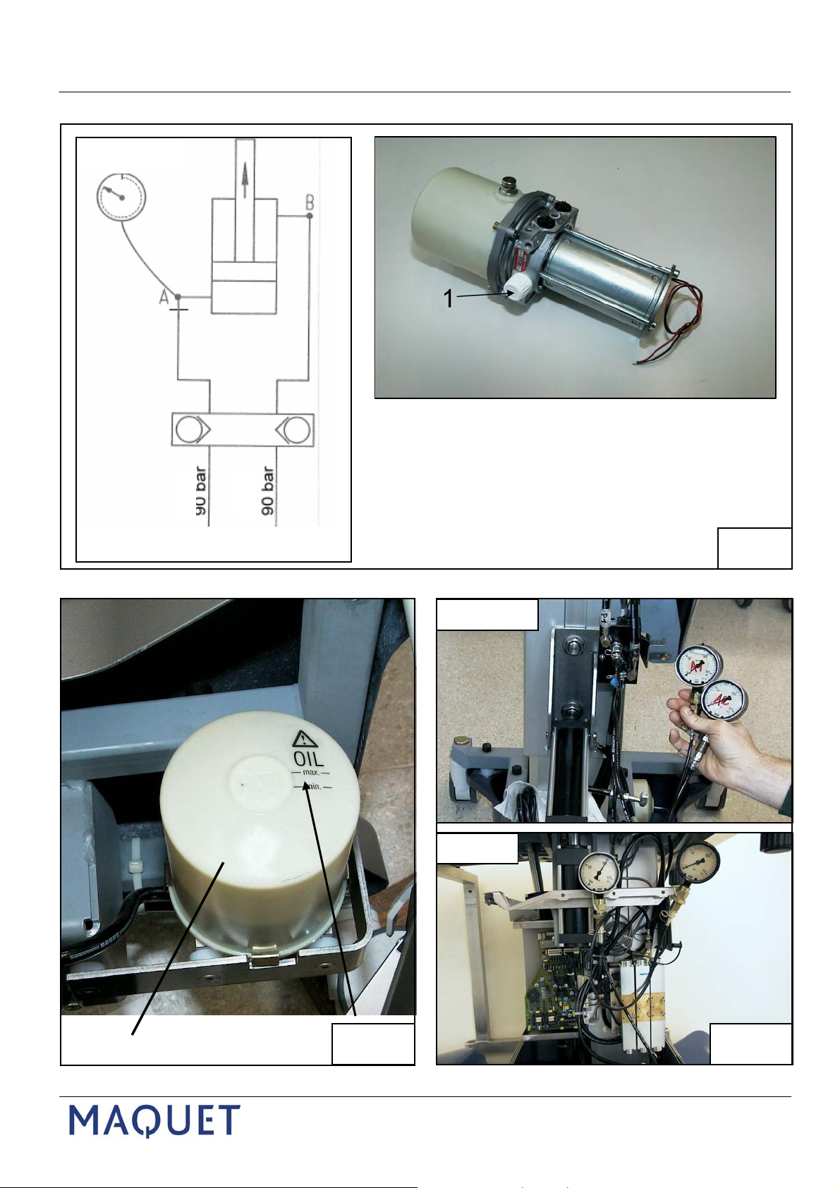
3.1
Check of hydraulic fluid level
Adjust the O.R. table to its uppermost position. Adjust the table top to a horizontal position.
Move the base casing upward and secure it to the table top.
Fluid level should be above the minimum and below the maximum markings at the tank (4).
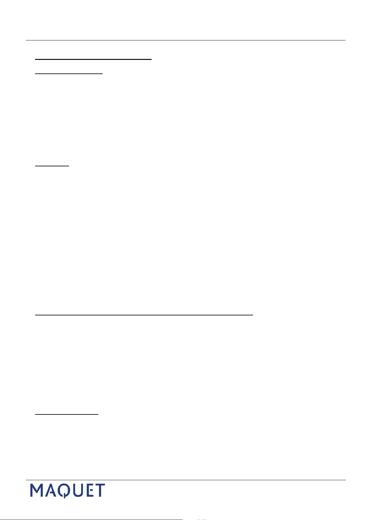
3.2
System pressure
The nominal system pressure of O.R tables 1118.01 and .02 is 90 bar, - for 1118.03 it is 100 bar.
This pressure can be tested at any cylinder as follows:
Connect a pressure gauge to the “A”-line of the cylinder and extend the cylinder to its maximum
position.
If the system pressure is too low it can be readjusted at the pressure limiter valve “DB 90” (DB 100 for
1118.03).
Tolerance: + 5 bar.
If the correct pressure cannot be obtained by adjustment, the DB90/DB100, the pump, or the motor is
probably defective (motor test!
3.3
Hydraulic cylinder
Inspect hydraulic cylinders for visible leakages.
Test the lowering valve (1118.01 / 02) or check valve (1118.03) (measure without the cylinder).
If the valve is found to be working correctly the cylinder must be replaced.
1118.0XGB_ 06 Page: 10
Page 12

Wartungs- und Reparaturanleitung Alphaclassic / Betaclassic
Maintenance and Repair Instruction
1118.01/02
1118
3
5
1118.03
3
3.4
1118.0XGB_ 06 Page: 11
Page 13

Wartungs- und Reparaturanleitung Alphaclassic / Betaclassic
Maintenance and Repair Instruction
1118
3.4
Oil tightness of the double check valve (3) or lowering valve (5)
To test oil tightness of the valve (3) or (5) the function in question must be free from mechanical load and
supported to prevent it from moving.
For types 1118.01 and 1118.02:
Lowering valve (3)
Remove hydraulic lines “A” and “B”
Connect the pressure gauge by means of the measuring adapter included in the tool kit (3111.4913).
Actuate the function “tilting” or “
The pressure must rise to a maximum of 90 bar. Release the pedal. The valve (3) must close.
trendelenburg” depends on which valve you check.
Within the following 10 minutes the pressure must not drop below 70 bar
Please note the pressure diagram "Y".
If the pressure suddenly drops at the beginning by app. 10...30 bar and remains constant thereafter, bleed the
measuring lines and repeat the measurement.
Lowering valve (5)
Remove the height cylinder
Remove hydraulic line from the cylinder
Connect the pressure gauge to the hydraulic line by means of the measuring adapter included in the tool kit
(3111.4913).
Actuate the function “up” .
The pressure must rise to a maximum of 90 bar. Release the pedal. The valve (5) must close.
Within the following 10 minutes the pressure must not drop below 70 bar
If the pressure suddenly drops at the beginning by app. 10...30 bar and remains constant thereafter, bleed the
measuring lines and repeat the measurement.
10 min
1118.01/02
5 10 15 20 min
1118.0XGB_ 06 Page: 12
Page 14

Wartungs- und Reparaturanleitung Alphaclassic / Betaclassic
Maintenance and Repair Instruction
1118
1118.0XGB_ 06 Page: 13
Page 15

Wartungs- und Reparaturanleitung Alphaclassic / Betaclassic
Maintenance and Repair Instruction
1118
Check valve (type 1118.03)
To test oil tightness of the valve (3) the function in question must be free from mechanical load and
supported to prevent it from moving.
To test oil tightness of the valves (3) the segment in question must be free from mechanical load and
secured.
Check valve (3):
Disconnect the hydraulic lines A and B of the valve to be tested at the
valve block. Close the open ends of the hydraulic lines.
Connect the pressure gauge along with the measurement adapter
of the hydraulic tool kit (3111.4913).
Actuate the function “up” (or “down”) at the hand control.
The pressure must rise to its maximum (100bar).
Release the button, the valve (3) must close.
The presssure of 100 bar must not drop below 70 bar within a period of 30 min.
See graph in the pressure diagram "Y"
If the pressure suddenly drops at the beginning by app. 10 bar
and remains constant thereafter, bleed the measuring lines and
repeat the measurement.
This procedure is applicable in the same way for all of the 3 valves.
3.5
Potentiometers for "0"-(Level) adjustment (1118.03 only)
B3/tilting, B4/trendelenburg
Supply voltage is 5 Volt – measured at the connected potentiometer between the red and the black
wire
The "0"-position refers to app. 2,5 Volt measured between the
Troubleshooting:
red and the green wire (voltage divider).
- Function moves in the opposite direction when “0”-button is pressed:
→ Possibly red and black wire have been reversed.
- There is a continuous tone when the "0"-button is pressed:
A potentiometer is defective or positioned outside its permitted range (0,15.. 4,8V)
Re-adjust or replace.
1118.03
1118.0XGB_ 06 Page: 14
Page 16

Wartungs- und Reparaturanleitung Alphaclassic / Betaclassic
Maintenance and Repair Instruction
3.6
Corded hand control (1118.03 only)
Functions of the hand control can be simulated by means of the override keypad A2.
If functions can be moved by the override panel but not by hand control, either the hand control or the
controller unit A1 is defective.
Test the functions with another hand control, or with the IR-Tester. If there is
still no movement, the controller unit A1 is defective.
The corded hand control can be tested with the IR tester in the mode Modus „READ DATA-BUS 1132“
Test whether the supply voltage for the hand control (5 Volt) is present.
3.7
IR- remote control (1118.03 only)
Test IR-remote control functions and function of the charging station with the IR tester (mode “1118”)
Check to see that selector switches of the remote control and of the board A4 are set to the same
code.
Test the IR preamplifiers B1/B2 with the IR tester.
If a continuous tone is emitted by the IR transmitter, the code has been altered but not acknowledged.
See also technical description.
Note:
The IR-Code must also be acknowledged on the board A4 by means of the button S3.
If the board has been replaced and the code is not acknowledged on the new board, also the
functions of the corded hand control will not be enabled!!
1118
1118.0XGB_ 06 Page: 15
Page 17

Wartungs- und Reparaturanleitung Alphaclassic / Betaclassic
Maintenance and Repair Instruction
1118
4. Troubleshooting – what to do if...
In the course of troubleshooting please always proceed in the correct order of testing parts to ensure that the
defective part can be localised and identified.
Random testing of different components will hardly be crowned with success.
Procedure : e.g. for “no function at all”: transformer, charger board /charging voltage, batteries, Motor function/
voltage / current, pressure of the hydraulic pump...
4.1
Motor is running without the pedal being actuated (for 1118.02):
Check the micro switch at the pedal. Disconnect the micro switch and check if the motor is still running, Check the
charger board, replace it if necessary.
4.2
Motor is working correctly but no movement is carried out (for 1118.02)
Set the selector calotte to neutral position and adjust the column to its uppermost position.
Check the switch function of the calotte, replace the 6/3 channel valve if necessary.
A channel within the lowering valve may be blocked (tilting and trendelenburg functions fail)
4.3
Height adjustment moves downward only very slowly or not at all, or the height cylinder is sinking
down without being actuated
Other functions work correctly
-Test cylinder, pressure measurement, dynamic (backward) pressure too high, system pressure too low
-Too much friction in the guiding, Height adjustment upward (with no load on the table) at app. 40-50bar (2)
-Test the double check valve, pressure measurement (I, II)
4.4
Trendelenburg or tilting cylinder show some play at the piston rod after some time (1...2 days), or the
cylinder is sinking down without being actuated
-Test the double check valve
-Measure the pressure of A- and B-line
-Test the cylinder
4.5
No function at all
Connect the O.R. table to the mains supply. If the motor can then be actuated, charge the batteries for app. 1...2 h
and test functions again with no mains connection.
If there is still no function with the mains supply connected test the transformer, charger etc. ...
-Measure the current consumption of the motor
-still no function: test motor, batteries, charger...
1118.0XGB_ 06 Page: 16
Page 18

Wartungs- und Reparaturanleitung Alphaclassic / Betaclassic
Maintenance and Repair Instruction
1118
5
1118.0XGB_ 06 Page: 17
Page 19

Wartungs- und Reparaturanleitung Alphaclassic / Betaclassic
Maintenance and Repair Instruction
5. Repairwork, Replacement of hydraulic and mechanical components
5.1
Replacement of the column casings and the bellows
Bellows
Lock the O.R. table on the floor.
Remove all screws (4) of the seat plate (3).
Remove the seat plate (3).
Remove 6 screws (7).
Secure the column casings to prevent it from dropping
Remove all the rivets (1) of the bellows (2) .
Lower the casings and remove the bellows.
Column casing
Bend the 2 clips (10) of the uppermost segment of the casings (5) to enable removal of the bracket
(11).
Remove the uppermost segment of the casings.
Disassemble the centre part of the casings in the same order.
Remove the 3 screws (8) of the lower casing part.
Disassemble the lower part of the casings as described above.
Removal of the base casing:
1118
Remove 4 fixation screws (12).
The base casing (9) can now be removed from the base in an upward direction.
Plase note:
To replace the base casing the table top must be separated from the column – see 5.2
(column guiding).
1118.0XGB_ 06 Page: 18
Page 20

Wartungs- und Reparaturanleitung Alphaclassic / Betaclassic
Maintenance and Repair Instruction
1118
1118.0XGB_ 06 Page: 19
Page 21

Wartungs- und Reparaturanleitung Alphaclassic / Betaclassic
Maintenance and Repair Instruction
5.2
Guiding
Separate the table top from the column:
Adjust the column to its uppermost position.
Remove the bellows. Lower the column casing.
Adjust the tilting movement fully to the left hand side.
Secure the table top to prevent it from lateral moving.
Remove the upper pivot bolt (1) of the tilting cylinder (2).
Actuate the tilting movement and move the piston rod into fully the cylinder.
Support the table top by means of the assembly trolley as shown.
Remove the upper bolt (3) of the trendelenburg cylinder (4).
Actuate the trendelenburg movement and move the piston rod into fully the cylinder.
Loosen the nut (5), remove the velcro strip (6)
Remove the tilting bolt (7) and the fork support (8).
Please note:
Pay attention to the position of the fork support (8):
The bevel in the cut must be located downward (piston rod of trendelenburg cylinder).
Actuate the height movement and move the piston rod into fully the cylinder.
Move the assembly trolley with the table top to the side.
Remove the frame plate (10), pay attention to the position of assembly.
Replace the column guiding:
Fully extend the height cylinder.
Disconnect and stopper the hydraulic lines P1 and P2 of the trendelenburg cylinder.
Remove the trendelenburg cylinder (4) along with the valve (11).
Mark the position of the hydraulic lines.
Actuate the height movement and move the piston rod into fully the cylinder.
Disconnect and stopper the hydraulic lines P1 and P2 of the tilting cylinder.
Remove the fixation bow (12) of the height cylinder and the lateral bolt (13). Pay attention to
the distance washers (2pcs at the valve side, 1 at the opposite side).
Remove the tilting frame (14).
Remove the column casings and the upper base casing.
Tilt the O.R. table aside by 90° and remove the lower column casing.
Remove the 4 screws (15) of the guiding (16) and remove the guiding unit.
Remove all assembled parts (17) from the column and use them for the new column.
Assembly in reverse order.
Please note:
Functional test.
Pay attention to the position of the fork support (8):
The bevel in the cut must be located downward (piston rod of trendelenburg cylinder).
Ensure that the guiding is fixed in a parallel position.
1118
1118.0XGB_ 06 Page: 20
Page 22

Wartungs- und Reparaturanleitung Alphaclassic / Betaclassic
Maintenance and Repair Instruction
1118
1
5
2
3
8
6
4
7
2
1118.0XGB_ 06 Page: 21
Page 23

Wartungs- und Reparaturanleitung Alphaclassic / Betaclassic
Maintenance and Repair Instruction
1118
5.3
Castors with brake lever
Fixed castors:
Move the table top to its uppermost position and lock it on the floor.
Loosen the base casing, move it upward and secure it to the table top.
Remove 2 screws (1).
Support the O.R. table at the centre part.
Remove the castor (2) in a downward direction.
Ensure that the castor is positioned correctly.
Assemble in reverse order.
Secure the screws (1) with Loctite 245.
Locking castors with brake lever:
Remove the fixation screws (3) of the actuator shaft (4).
Tilt the O.R. table aside and lay it down on the floor.
Warning:
Release the brake lever (5).
Remove 4 screws (6) of the castors (7).
Remove the grub screw (8) of the locking lever.
Pull the actuator shaft (4) out of its guide holes (use the bolt removal tool).
Remove the brake lever (5).
Remove the castor (7).
Assembly in reverse order.
Ensure that the castor is positioned correctly.
Secure the screws (6) with Loctite 245.
Functional test.
Pay attention to the base casing (possibility of breakage!)
1118.0XGB_ 06 Page: 22
Page 24

Wartungs- und Reparaturanleitung Alphaclassic / Betaclassic
Maintenance and Repair Instruction
1118
1
2
3
5
T
4
P
5.4
1118.0XGB_ 06 Page: 23
Page 25

Wartungs- und Reparaturanleitung Alphaclassic / Betaclassic
Maintenance and Repair Instruction
5.4
Pedal actuated pump
This pump is to be replaced along with the pump lever (one assembly group)
Loosen the upper base casing, lift it up and secure it to the table top. Adjust the column to the uppermost
position.
Type 1118.02:
Disconnect the O.R. table from the mains supply.
Unplug X5 at the charger board (voltage supply)
Remove the micro switch (1)
Tilt the O.R. table to one side and lay it down on the floor.
Remove the lower base casing.
Press the pump lever (2) downward and remove the upper fixation screws (3).
Disconnect and stopper hydraulic lines „P“ and „T“ of the pump (4).
Close the connectors of the pump by means of stopper screws.
Remove the lower fixation screws (5).
Replace the pedal pump.
Assemble in reverse order.
Please note:
Always use new seal rings.
Actuate all functions several times and move them to their final positions (see “bleeding”).
Check the oil level.
1118
1118.0XGB_ 06 Page: 24
Page 26

Wartungs- und Reparaturanleitung Alphaclassic / Betaclassic
5.5
Maintenance and Repair Instruction
1118
2
5
4
1
3
6
1118.0XGB_ 06 Page: 25
Page 27

Wartungs- und Reparaturanleitung Alphaclassic / Betaclassic
Maintenance and Repair Instruction
5.5
6/3 directional valve with switch tray
Please note:
If the 6/3 directional valve has to be replaced ensure that you have also a new switch tray 0799.2212) at
hand – it may be destroyed during replacement work.
Loosen the base casing, lift it and secure it to the table top.
Adjust the column to uppermost position.
Loosen the locking nut (1) .
Unscrew the switch tray (2) .
Remove 4 screws (3), remove the guide plate (4).
Tilt the O. R. table and lay it down on the floor.
Remove the lower base casing.
Mark the position in which the 6/3 directional valve (5) is fixed.
Disconnect all hydraulic lines and stopper them.
Remove 3 fixation screws (6).
Replace the valve.
Assemble in reverse order.
The switch tray must be secured with Loctite.
The valve must be positioned in a way that the switch tray can move freely in all directions. However
there must be no space between the tray and the upper base casing.
The position can be corrected in that the fixation screws are loosened and the valve is moved laterally.
Please note:
Always use new sealing rings.
Check the oil level.
Actuate all functions several times and move them to their final positions (see “bleeding”).
1118
1118.0XGB_ 06 Page: 26
Page 28

Wartungs- und Reparaturanleitung Alphaclassic / Betaclassic
Maintenance and Repair Instruction
1118
1
2
1118.0XGB_ 06 Page: 27
Page 29

Wartungs- und Reparaturanleitung Alphaclassic / Betaclassic
Maintenance and Repair Instruction
5.6
Lowering valve (Model 1118.01/02)
Loosen the base casing, lift it up and secure it to the table top.
Adjust the column to the uppermost position.
Tilt the O.R. table and lay it down on the floor.
Remove the lower base casing.
Disconnect and stopper all hydraulic lines.
Remove 3 fixation screws(1).
Replace the lowering valve (2) .
Use the spring, spring tray, and the slide element for the new valve.
Assemble in reverse order.
Always use new sealing rings.
Check the oil level.
Test all functions.
1118
1118.0XGB_ 06 Page: 28
Page 30

Wartungs- und Reparaturanleitung Alphaclassic / Betaclassic
Maintenance and Repair Instruction
1118.01 / 02 1118.03
1118
4
X12
X2
1
3
5
2
6
7
height tilt trendelenburg
1118.0XGB_ 06 Page: 29
Page 31

Wartungs- und Reparaturanleitung Alphaclassic / Betaclassic
Maintenance and Repair Instruction
1118
5.7
Replacement of double check valves (types 1118.01 and .02 only)
Remove the column casing (see 5.1)
Support the segment in question (cylinder) of the valve to be replaced to prevent it from moving
during service work
Disconnect the hydraulic lines (1) of the valve (2) and stopper them.
Remove 2 fixation screws (3) of the valve and remove it.
Assemble in reverse order.
Apply some vaseline grease onto the o-rings before assembly.
Torque down the hollow screws (4) at 10 Nm.
Replacement of 5/3 directional valve, (type 1118.03)
Remove the column casing (see 5.1)
Support the segment in question (cylinder) of the valve to be replaced to prevent it from moving
during service work
Disconnect the connectors of the 5/3 directional valve (6) at the plugs X2 or X12.
Remove the 3 fixation screws (5) of the 5/3 directional valve (6) and remove the valve (6) along with the
check valve (7).
Replace the 5/3 directional valve (6) / the check valve (7).
Assemble in reverse order.
Apply some vaseline grease onto the o-rings before assembly.
1118.0XGB_ 06 Page: 30
Page 32

Wartungs- und Reparaturanleitung Alphaclassic / Betaclassic
Maintenance and Repair Instruction
1118
5
6
7
3
1
3
2
1
4
3
1118.0XGB_ 06 Page: 31
Page 33

Wartungs- und Reparaturanleitung Alphaclassic / Betaclassic
Maintenance and Repair Instruction
5.8
Replacement of cylinders
Height cylinder (1118.01 and .02 only)
Remove the seat plate.
Loosen the bellows.
Adjust the column of the O.R. table to lowermost position.
Remove the fixation brackets (5).
Tilt the O.R. table and lay it down on the floor.
Remove the lower base casing.
Remove 6 fixation screws (6) of the cylinder.
Remove the cylinder and disconnect the hydraulic line (7).
Assemble in reverse order.
Torque the hollow screw of the hydraulic line down at 12-14 Nm.
Check oil level..
Functional test.
Height cylinder ( Variante 1118.03)
Separate the table top from the column.
Adjust the column of the O.R. table to lowermost position.
Remove the casings of the base and the column.
Set the O.R. table on wooden blocks.
Remove the fixation screw (6) of the cylinder.
Pull the cylinder off and disconnect the hydraulic line (7).
Assemble in reverse order.
Torque the hollow screw of the hydraulic line down 12-14 Nm.
Check oil level..
Functional test.
Tilting and trendelenburg cylinders
Remove the column casings (see 5.1)
Support the segment in question (cylinder) to prevent it from moving during service work.
Remove the upper pivot bolt (1) of the cylinder.
Fully move the piston rod into the cylinder.
Disconnect the hydraulic lines from the cylinder and stopper them.
Remove the lower pivot bolt (2).
Use the fork support (3) of the tilt cylinder or the piston head (4) of the trendelenburg cylinder for the new
cylinder and secure it with Loctite.
Assemble in reverse order with new cylinder.
Always use new sealing rings.
Torque the hollow screws down at 10 Nm.
Check oil level.
Functional test.
1118
1118.0XGB_ 06 Page: 32
Page 34

Wartungs- und Reparaturanleitung Alphaclassic / Betaclassic
Maintenance and Repair Instruction
1118.02
1118
1118.02
1
1118.03
1
2
3
4
1118.0XGB_ 06 Page: 33
Page 35

Wartungs- und Reparaturanleitung Alphaclassic / Betaclassic
Maintenance and Repair Instruction
5.9
Hydraulic unit, motor (1118.02, 1118.03)
Hydraulic unit:
Disconnect the O.R. table from the mains supply.
Loosen the base casing, lift it up and secure it to the table top.
Unplug X3 from the charger board.
Lift and support the table at the side where the tank is located.
Remove the lower base casing.
Unscrew „P“ and „T“ lines and stopper them.
Disconnect the grounding cable from the motor housing.
Remove the fixation screws (1) and remove the hydraulic unit.
Assemble in reverse order.
Motor only:
Remove the hydraulic unit as described above.
Remove 4 screws (2), separate the motor (3) from the pump (4) and replace it by the new motor.
Hydraulic pump:
The hydraulic pump (4) can be replaced as well without using a new motor.
Please note:
The hydraulic pump can only be replaced along with the tank (assembly unit)
1118
1118.0XGB_ 06 Page: 34
Page 36

Wartungs- und Reparaturanleitung Alphaclassic / Betaclassic
Maintenance and Repair Instruction
1118
1
2
3
4
5
X5
8
6
7
9
10
11
+
1118.0XGB_ 06 Page: 35
Page 37

Wartungs- und Reparaturanleitung Alphaclassic / Betaclassic
Maintenance and Repair Instruction
5.10
Charger board, batteries (1118.02)
Charger board:
Disconnect the O.R. table from the mains supply.
Loosen the upper base casing (3), lift it up and secure it to the table top.
Remove 2 screws (1) of the cover (2), remove the cover.
Unplug all cables from the charger board (6).
Disconnect the grounding cable from the motor housing.
Remove the 2 fixation screws (5) of the charger board (6) (aluminium rail) in the base and remove the
charger board.
Assemble in reverse order.
Please note:
Measure the charging voltage, test the functions.
Batteries:
Disconnect the O.R. table from the mains supply.
Loosen the upper base casing (3), lift it up and secure it to the table top.
Remove 2 screws (1) of the cover (2), remove the cover.
Unplug X5 from the charger board (6).
Lift the table somewhat from the floor and support it. Remove the lower base casing.
Remove 2 screws (8).
Remove the screws (4) and (7) and remove both the batteries (10) with the fixation bracket (9).
Disconnect the cables (11) from the batteries.
Remove the batteries (10)
Assemble in reverse order.
Pay attention to the polarity markings (red“+“, black“-“)
Please note:
Measure the charging voltage, test the functions.
Connect the O.R. table to the mains supply at first, connect the batteries at the very last.
(plug X5)
Connect the O.R. table to the mains supply at first, connect the batteries at the very last.
(plug X5)
1118
1118.0XGB_ 06 Page: 36
Page 38

Wartungs- und Reparaturanleitung Alphaclassic / Betaclassic
Maintenance and Repair Instruction
1118
1
3
4
2
6
7
X5
5
9
8
+
+
1118.0XGB_ 06 Page: 37
Page 39

Wartungs- und Reparaturanleitung Alphaclassic / Betaclassic
Maintenance and Repair Instruction
Charger board, batteries (1118.03)
Charger board:
Disconnect the O.R. table from the mains supply.
Loosen the upper base casing (1), lift it up and secure it to the table top.
Remove the cover (2).
Unplug all cables from the charger board (3).
Disconnect the grounding cable from the motor housing.
Remove the 2 fixation screws (4) of the charger board (3) (aluminium rail) in the base and remove the
charger board.
Assemble in reverse order.
Pay attention to the polarity markings (red“+“, black“-“)
Please note:
Batteries (1118.03):
Disconnect the O.R. table from the mains supply.
Loosen the upper base casing (1), lift it up and secure it to the table top.
Remove the cover (2).
Unplug X5 from the charger board.
Lift the table somewhat from the floor and support it. Remove the lower base casing.
Remove 2 screws (5).
Remove the fixation bracket (6) and the insulation paper.
Disconnect the cables (8) from the batteries.
Remove the batteries (9)
Assemble in reverse order.
Pay attention to the polarity markings (red “+“, black “-“)
Please note:
Connect the O.R. table to the mains supply at first, connect the batteries at the very last.
(plug X5)
Connect the O.R. table to the mains supply at first, connect the batteries at the very last.
(plug X5)
1118
1118.0XGB_ 06 Page: 38
Page 40

Wartungs- und Reparaturanleitung Alphaclassic / Betaclassic
Maintenance and Repair Instruction
1118
1
7
2
3
8
5
4
11
10
9
1118.0XGB_ 06 Page: 39
Page 41

Wartungs- und Reparaturanleitung Alphaclassic / Betaclassic
Maintenance and Repair Instruction
5.11
Gas spring
Turn the gas spring (7) to the front and unscrew it.
Gas spring of backrest
Loosen the locking nut (1) .
Remove the circlip (2) remove the pivot bolt (3) to the outside.
Pay attention to the distance sleeves (4) and (5) .
Assemble in reverse order.
Please note:
The actuator pin of the gas spring (7) must be fully released as long as it is not actuated.
Gas spring of the legplate
Loosen the locking nut (10) .
Loosen the grub screw (8) and remove the shaft (9) to the outside.
Turn the gas spring (11) upward and unscrew it.
Assemble in reverse order.
Please note:
The actuator pin of the gas spring (11) must be fully released as long as it is not actuated.
1118
1118.0XGB_ 06 Page: 40
Page 42

Wartungs- und Reparaturanleitung Alphaclassic / Betaclassic
Maintenance and Repair Instruction
1118
1
2
3
4
5
6
8
9
10
11
12
13
14
7
1118.0XGB_ 06 Page: 41
Page 43

Wartungs- und Reparaturanleitung Alphaclassic / Betaclassic
Maintenance and Repair Instruction
5.12
Longitudinal movement – Bowden-cable (Variante “J”, “K”)
Disassembly:
Remove 3 screws (1).
Remove the locking plate (3) from the strut (2).
Loosen 2 grub screws (10).
Pull the traction cable (4) back. Remove the spring guide (11) and the spring (9).
Completely remove the bowden cable (7).
Assembly:
Separate the cable (4) from the guide hose, route it through the actuator handle (6) and through the
adjustment screw (5).
Push the cable (4) back into the guide hose.
Assemble 3 wire sleeves (13) onto the end pieces of the cable (4) and solder or crimp them.
Place the traction cable (7) into the strut (2) and rout the end piece through the hole for the locking plate
(3) to the outside.
Fully push the locking catch (14) back and fix it by means of a grip tool.
Route the cable (4) through the adjustment screw, the eye of screw (8), the spring (9), and the guide (11).
The end piece of the cable (4) must be outside the spring guide by app.2.5 mm.
Tighten the 2 grub screws (10).
Adjust the screws (5) and (12) to 6mm and lock them.
Remove the grip tool.
Actuate the handle (6) up to the stop. The locking catch (14) must disappear up to the top of the locking
plate (3). Correct by screw (12) if necessary.
Insert the locking plate (3) into the strut (2).
Tighten the 3 screws (1) and secure them with Loctite243.
Functional test:
When the handle (6) is actuated, there must be a distance of app. 1mm between the locking catch (14)
and the frame. Correct with screw (5) if necessary.
The longitudinal movement is only enabled as long as the table top is in level position.
The table top can be locked in 9 positions when the handle (6) is released (9x 36,5mm distance from one
position to the other).
1118
1118.0XGB_ 06 Page: 42
Page 44

Wartungs- und Reparaturanleitung Alphaclassic / Betaclassic
Maintenance and Repair Instruction
1118
1
2
3
4
5
1118.0XGB_ 06 Page: 43
Page 45

Wartungs- und Reparaturanleitung Alphaclassic / Betaclassic
Maintenance and Repair Instruction
5.13
Longitudinal movement – linear guide ( types “J” and “K” )
Disassembly
Adjust the column to the uppermost position,
adjust the table top to level position.
Support the table top by means of the assembly trolley.
Remove the seat plate (1).
Open the bellows (3) as far as necessary.
Remove 4 screws (2) at each side.
Lower the O.R. table to enable the table top on the trolley to be rolled aside.
Support the linear guide (4) to prevent it from dropping.
Remove all fixation screws (5) of the linear guide (4).
Remove the linear guide with the carriage.
Assemble in reverse order.
1118
1118.0XGB_ 06 Page: 44
Page 46

Wartungs- und Reparaturanleitung Alphaclassic / Betaclassic
Maintenance and Repair Instruction
1118
1
4
5
6
3
2
7
10
9
8
11
14
13
12
15
13
1118.0XGB_ 06 Page: 45
Page 47

Wartungs- und Reparaturanleitung Alphaclassic / Betaclassic
Maintenance and Repair Instruction
5.14
Replacement of the gear parts (spindle, cog wheels) of the body elevator (types “G”, “H”)
Disassembly:
Adjust the table top to a horizontal position.
Remove the parts in the order as follows:
the fixation screws (1) of of the back plates (2).
both back plates (2).
the cover plates (3).
the bearing bolt (4).
2 screws (5) of the lateral support bar (6) at one side.
the grub screws (8) of the securing rings (9) at both sides of the drive tube (7).
Slide the securing rings (9) aside and remove the cylindric pin (10).
Slide the securing rings (9) back onto the drive tube (7)
Carefully push the back struts (11) apart, - only so far that the drive tube (7) can be removed.
Remove the securing ring (12) from the shaft (13) ang remove the cog wheel.
Remove the fitting key (15).
The sahft (13) can be removed in a lateral direction.
1118
1118.0XGB_ 06 Page: 46
Page 48

Wartungs- und Reparaturanleitung Alphaclassic / Betaclassic
Maintenance and Repair Instruction
1118
16
17
18
22
19
20
10
23
7
13
1118.0XGB_ 06 Page: 47
Page 49

Wartungs- und Reparaturanleitung Alphaclassic / Betaclassic
Maintenance and Repair Instruction
Disassembly:
Remove the closing cap (16).
Remove the spring pin (17).
Hold the spindle nut (18) in place and rotate the spindle (19) in order to remove it along with the
cog wheel (20).
Remove the distance tube (21) and the spindle nut (18) along with the connecting rod (22).
Separate the spindle nut (18) from the connecting rod (22).
If necessary the 2 bearing sleeves (23) can also be replaced at this stage.
Assemble in reverse order.
Please note:
To ensure parallel positioning pay attention to the following order of assembly:
The drive tube (7) is to be installed after all the other parts of the gear are in place.
When the drive tube (7) has been positioned, connect it to the shaft (13) at one side only.
Now both sides must be rotated up to the upper stop.
Then the remaining side of the drive tube (7) can also be connected to the shaft (13).
If necessary the drive tube (7) must be rotated somewhat towards the next fixing hole of
the shaft (13).
All gear parts must be lubricated with Molykote DX white (Mat.No. 5822.0040)
Carry out a functional test.
1118
1118.0XGB_ 06 Page: 48
Page 50

Wartungs- und Reparaturanleitung Alphaclassic / Betaclassic
Maintenance and Repair Instruction
1118
1
2
A1
A1
A4
S3
6
1118.0XGB_ 06 Page: 49
Page 51

Wartungs- und Reparaturanleitung Alphaclassic / Betaclassic
Maintenance and Repair Instruction
5.15
Controller unit A1 and IR receiver board A4 (1118.03 only)
Disconnect the O.R. table from the mains supply
Loosen the fixation of the column casing and move the casing downward.
Remove the cover plate (1)
Disconnect all the connectors of the controller board A1 and the IR receiver board A4.
Remove the fixation screws (2) – Remove the Controller board A1 along with the IR receiver board A4.
Separate the IR receiver board A4 from the controller unit A1.
Replace the board(s) if necessary.
Set the IR code on the new board A4 by means of the 2 code switches (6).
Install both boards in reverse order.
Connect all the plugs on the boards.
Acknowledge the code on the board A4.
Please note:
The IR code must always be acknowledged by means of the button S3 on the board A4.
If the board was replaced but the IR code has not been acknowledged, also the functions of the
corded hand control will not be enabled!
1118
1118.0XGB_ 06 Page: 50
Page 52

Wartungs- und Reparaturanleitung Alphaclassic / Betaclassic
Maintenance and Repair Instruction
1118
B3
1
B4
1118.0XGB_ 06 Page: 51
Page 53

Wartungs- und Reparaturanleitung Alphaclassic / Betaclassic
Maintenance and Repair Instruction
5.16
Adjustment of the “O“- positioning - potentiometers (1118.03 only)
The “0”-positioning of the table top is controlled by potentiometers B3 (tilting) and B4 (trendelenburg).
The supply voltage for the potentiometers is 5V – measured between the red and the black connector
cables. The “0”-position refers to an output voltage of app. 2,5V – measured between the green and the
black connector cable – i.e. the centre of the adjustment range is 2,5V.
Adjustment (setting):
Move the table top to a horizontal position by means of the hand control (tilting, trendelenburg).
Unscrew the fixation of the column casing and move the casing downward.
Loosen the screw (1) and adjust the potentiometers to their centre position.
Switch the controller unit on and measure the output voltage (between the green and the black
connector cable). Adjust the potentiometer to a voltage of app. 2,5V.
Tighten the securing screw (1) of the potentiometer.
Adjust the 2
Carry out a functional test.
nd
potentiometer in the same way.
1118
1118.0XGB_ 06 Page: 52
Page 54

Q
g
g
Q
py
g
y
Q
,
MAQUET GmhH & Co. KG
Geschäftsbereich Service
Kehler Straße 31
76437 Rastatt/Germany
National
Service-Hotline 01 80/3 21 21 44
International
Service-Hotline +49/7222/932-745
E-mail: info.service@maquet.de
Internet: www.maquet.com
Technische und konstruktive Änderungen vorbehalten.
The right is reserved to make technical and design changes.
Sous réserve de modifications dues au développement technique.
Nos reservamos el derecho de hacer modificaciones conformes al desarrollo técnico.
Rastatt
UET
MA
ht © b
ri
UET GmbH & Co. KG. L Co
enes Warenzeichen der MA
etra
UET Ein
® MA
 Loading...