

Page 1
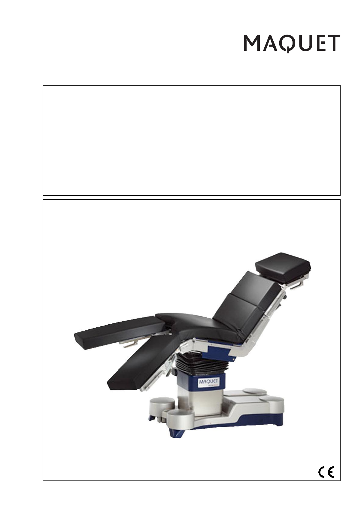
ALPHAMAXX 1133.12B1/B3/
F1/F3
Operating instructions
Universal
operating table
English
GA113312EN02
Page 2
1133.12B1/B3/F1/F3
9
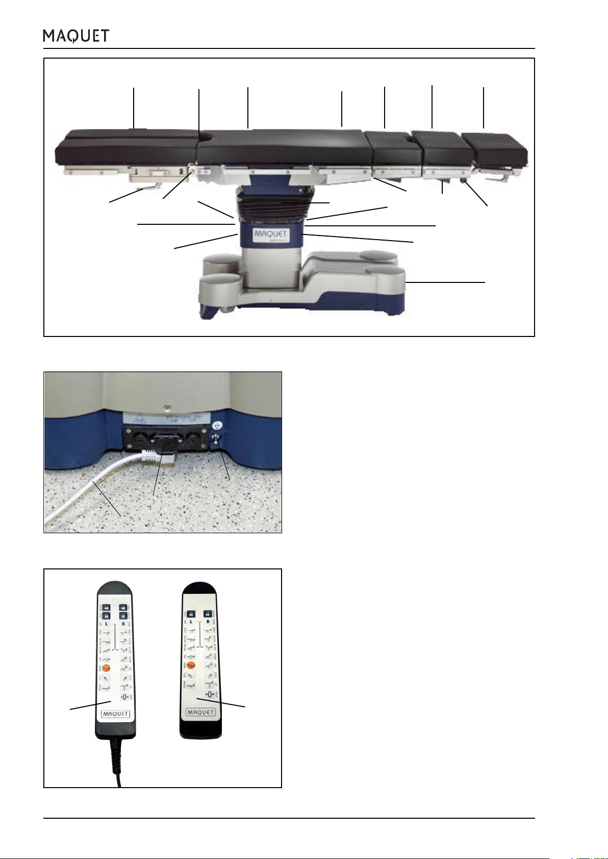
Pictorial guide
14
8
10
13
22
12
11
6
7
21
12
4
5
3
14
20
1
2
15
1. Head plate (e.g. 1130.64)
2. Fastening screws for head plate
16
15
3. Locking lever for extension segment
1131.31XX
4. Locking lever for extension segment
1131.31XX
(optional)
5. Mounting point for back plates
6. Lower back plate
17
7. Bellows
8. Leg plates 1133.53XX (optional)
9. Locking lever for leg plate abduction
10. Unlocking of leg plates
11. Seat plate
12. Infrared receiver and transmitter
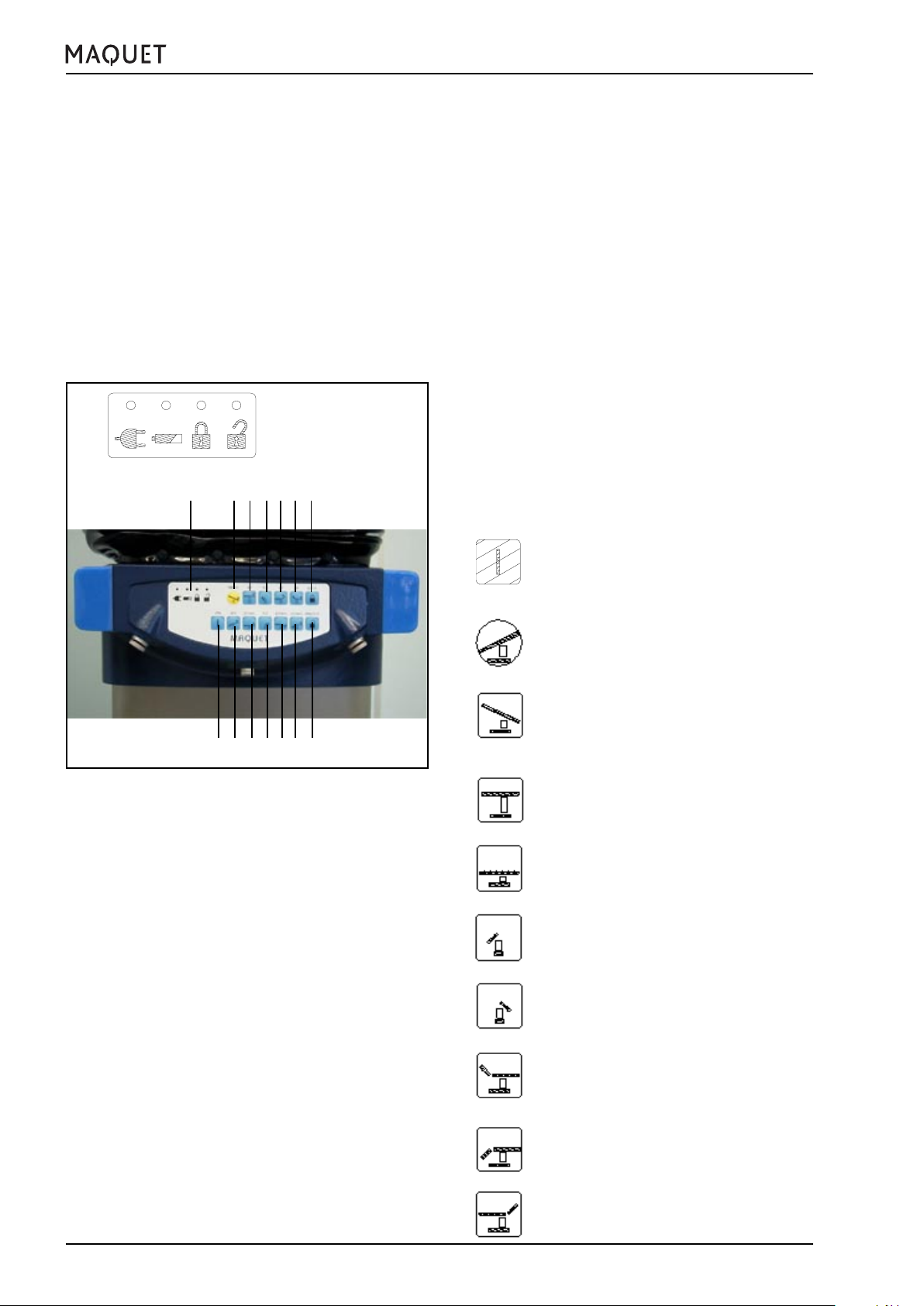
13. Override system with status indicators
for operating table (on the rear)
14. Sockets for corded hand control and
foot switch
15. Socket for mains cable
16. Mains cable
18
19
17. Potential equalization
18. Corded hand control (optional)
19. IR remote control (optional)
20. Interface for servicing (on the rear)
21. Seat plate extension 1131.55XX
(optional)
22. Mounting point for leg plates
2
GA113312EN02
Page 3

1133.12B1/B3/F1/F3
Table of contents
Pictorial guide ..................................................................................................................................... 2
I. Important safety notes.................................................................................................................. 5
II. Important information .................................................................................................................. 7
1. Important information on these operating instructions: .............................................................. 7
2. Intended use of an operating table ............................................................................................7
3. Intended purpose: .................................................................................................................... 7
4. Fundamental safety aspects ....................................................................................................7
III. General description...................................................................................................................... 8
1. General features ....................................................................................................................... 8
2. Control of functions .................................................................................................................. 9
2.1 Corded hand control ...................................................................................................... 10
2.2 Override system = emergency operation ........................................................................ 11
2.3 IR remote control (optional) ........................................................................................... 13
2.3.1 IR system code ................................................................................................... 14
2.3.2 Charging station ................................................................................................... 15
2.4 Control via IR wall control panel ..................................................................................... 15
2.5 Control via foot switch 1009.81DX (optional) .................................................................. 16
2.6 „Neurolock“ function ...................................................................................................... 16
3. Table top ................................................................................................................................17
3.1 General features ........................................................................................................... 17
3.2 Mechanical adjustments .............................................................................................. 18
3.2.1 Mount / remove the head plate ............................................................................. 18
3.2.2 Extension segment 1131.31B0/F0 ....................................................................... 23
3.3 Collision protection at the leg plate mounting point ....................................................... 24
3.3.1 Seat plate extensions ......................................................................................... 25
3.3.2 Leg plates ............................................................................................................ 26
3.4 Table top padding .......................................................................................................... 27
3.5 Accessories..................................................................................................................27
4. Autodrive in the base.............................................................................................................. 28
IV. Use of the operating table ......................................................................................................... 29
1. General .................................................................................................................................. 29
2. Operation on battery power .................................................................................................... 29
3. Operation on mains power...................................................................................................... 30
4. HF surgery, use of defibrillators .............................................................................................. 30
V. Patient positioning ..................................................................................................................... 31
1. General .................................................................................................................................. 31
2. Positioning a patient weighing between 225 kg and 450 kg (500 lb - 1000 lb) ......................... 33
2.1 Approved accessories ................................................................................................... 33
2.2 Operating table immobilized (LOCK) ............................................................................. 33
3. Positioning a patient weighing between 135 kg and 225 kg (300 lb - 500 lb) ........................... 34
3.1 Approved accessories ................................................................................................... 34
3.2 Operating table not immobilized (UNLOCK) .................................................................. 34
3.2.1 NORMAL patient orientation / operating table not immobilized (UNLOCK)............ 35
3.2.2 REVERSE patient orientation / operating table not immobilized (UNLOCK) ........ 36
3.3 Operating table immobilized (LOCK) ............................................................................. 37
3.3.1 NORMAL patient orientation / operating table immobilized (LOCK) ...................... 37
3.3.2 REVERSE patient orientation / operating table immobilized (LOCK) .................... 38
4. Positioning a patient weighing up to 135 kg (300 lb) ............................................................... 39
4.1 Approved accessories ................................................................................................... 39
4.2 Operating table not immobilized (UNLOCK) .................................................................. 39
4.2.1 General ................................................................................................................ 39
4.2.2 NORMAL patient orientation / operating table not immobilized (UNLOCK)............ 40
4.2.3 REVERSE patient orientation / operating table not immobilized (UNLOCK) ......... 41
4.3 Operating table immobilized (LOCK) ............................................................................. 42
4.3.1 NORMAL patient orientation / operating table immobilized (LOCK) ...................... 42
4.2.2 REVERSE patient orientation / operating table immobilized (LOCK) .................... 43
GA113312EN02
3
Page 4

1133.12B1/B3/F1/F3
VI. Care and maintenance .............................................................................................................. 44
1. Cleaning ................................................................................................................................. 44
2. Disinfection ............................................................................................................................ 44
3. Maintenance .......................................................................................................................... 45
4. Malfunctions .......................................................................................................................... 45
5. Environmental protection ........................................................................................................ 46
VII. Technical specifications ............................................................................................................. 47
1. Operating table adjustments .................................................................................................. 47
2. Electrical specifications ......................................................................................................... 47
VIII.List of accessories ...................................................................................................................... 48
1. Accessories for head-side mounting point: .............................................................................. 51
1.1 For patients weighing up to 450 kg (1000 lb) .......................................................................... 51
1.2 For patients weighing up to 225 kg (500 lb) ............................................................................ 51
1.3 For patients weighing up to 135 kg (300 lb) ............................................................................ 51
2. Accessories for the back plate mounting point........................................................................ 52
2.1 For patients weighing up to 450 kg (1000 lb) .......................................................................... 52
2.2 For patients weighing up to 225 kg (500 lb) ............................................................................ 52
2.3 For patients weighing up to 135 kg (300 lb) ............................................................................ 52
3. Accessories for leg plate mounting point................................................................................. 52
3.1 For patients weighing up to 450 kg (1000 lb) .......................................................................... 52
3.2 For patients weighing up to 225 kg (500 lb) ............................................................................ 52
3.3 For patients weighing up to 135 kg (300 lb) ............................................................................ 52
4. Accessories for side rails ........................................................................................................... 53
5. Special-purpose accessories ..................................................................................................... 54
6. Control units ................................................................................................................................54
IX. Spare parts list............................................................................................................................ 55
4
GA113312EN02
Page 5
1133.12B1/B3/F1/F3
I. Important safety notes
I. Important safety notes
Mount only the accessories listed in chapter VIII.
Make sure the operating table is set up horizontally and that it is stable.
Immobilize the operating table prior to use! Press the LOCK button!
Immobilize the operating table prior to transferring the patient! Press the LOCK button!
The patient may be transferred only from the side of the operating table. If the patient is transferred from
head or foot end, there is a danger of tipping over!
Injury hazard!
If the patient is not secured during transportation, when adjusting the operating table or when positioning the
patient (particularly when the slope feature is used), then the patient could slip, uncontrolled, off the operating table. Always secure the patient and maintain continuous observation.
Hazard of burns to the patient!
When using HF surgical equipment, defibrillators and defibrillation monitors, make sure to avoid that the
patient comes into contact with metal parts of the operating table, the table tops or the accessories. Also
make sure to avoid that the patient is lying on moist underlays or sheets on the conductive pads.
Be absolutely sure to comply with the manufacturers operating instructions!
Hazard of damage!
Avoid any collisions between the accessories and the operating table during adjustment procedures!
Consult MAQUET prior to using accessories produced by other manufacturers if they affect the longitudinal
geometry of the table top.
There is no explosion protection while recharging the batteries or when the operating table is on mains
power.
When connecting or removing the mains cable, observe the correct order of the procedure! (See page 22)
Avoid endangering the patient’s respiratory system, nerve pathways and circulatory system by ensuring the
patient is properly positioned and observing the patient’s condition.
The operating table’s electrical conductivity has to be checked once a year! This check should be performed only by trained servicing personnel.
Before opening the equipment, disconnect the mains plug.
Electrical devices (e. g. cellphones, radios, magnetic resonance tomographs) can interfere with the functioning of the operating table when used near the operating table.
Please observe the Technical Description for the operating table.
It contains imformation on electromagnetic compatibility (EMC) for the operating table (both radiation and
resistance to interference).
Adhere to those specifications when using electrical devices and respond properly in the event of effects on
your operating table.
GA113312EN02
5
Page 6
I. Important safety notes
Injury hazard!
Before aligning the leg plates horizontally, check
the patient’s position carfully, particularly when
using knee crutches.
Hazard of pinching and crushing!
Do not touch the side rails in the area of the joints
when adjusting the table top.
1133.12B1/B3/F1/F3
Hazard of pinching and crushing!
Hazard of pinching!
Do not reach under the table top or between the
table top components during adjustment procedures.
Hazard of pinching and crushing!
When immobilizing the operating table (LOCK),
the operator’s feet may be crushed or shorn.
When setting the operating table, keep enough
distance from the table base.
Hazard of damage!
Do not place any objects on the operating table
base.
Hazard of damage!
Do not press or pull on the covers of the joints.
Hazard of damage!
Make sure the cable of the hand control does not
get jammed when adjusting the operating table.
6
Collision hazard!
GA113312EN02
Page 7

1133.12B1/B3/F1/F3
II. Important information
II. Important information
Your hospital has opted for the 1133.12 operating table. We appreciate the confidence you have placed in us.
1. Important information on these operating instructions:
• Please read these operating instructions completely and carefully. They were written to familiarize you with
the features of this operating table.
• Be sure to always follow the instructions given here.
• Always store these operating instructions near the unit.
• In these operating instructions we have used the following symbols:
This symbol identifies information which is critical for safety as described in the international
standard applicable to the field of medicine.
Note
This symbol precedes all notes which will help to avoid operational difficulties.
X An “X” in the order number (e.g. 1133.53XX) stands in place of the different versions.
2. Intended use of an operating table
The operating tables distributed by MAQUET are to be used exclusively in the field of human medicine. Before the
equipment is used, all users must be instructed in its proper use. This familiarization session is confirmed in an
acceptance log. The location selected for the table must conform to the applicable standards and guidelines.
Before using the equipment, you must be absolutely certain that it is properly installed and maintained.
3. Intended purpose:
The operating table 1133.12 is used to support and position a patient for surgical treatment
• immediately before, during and after the operative phase,
• in rooms used for medical purposes which fulfil the following requirements:
- equipment to protect against electric shocks
- additional potential equalization
- electrically conductive floor (corresponding to Group 1 or 2 as per VDE 0100 Part 710)
• under medical supervision.
• A max. patient weight of 450 kg (1000 lb.) is permissible in certain circumstances.
Avoid excentric patient positions, i.e. the patient’s centre of gravity (near the navel) must be as close as
possible to the centre of the column.
The design of the table top makes the operating table suitable for every surgical discipline. The positioning options
are listed in the operating instructions.
The adjustments are made electrohydraulically using the corded hand control, the IR remote control, the IR wall
control panel or a foot switch.
Side rails are used to mount accessories, in accordance with the manufacturer’s instructions.
The radiotranslucent operating table top allows for intraoperative use of X-ray equipment.
Note:
In accordance with generally accepted hygiene standards, the operating table top is to be covered with
surgical drapes during use.
4. Fundamental safety aspects
This operating table meets the requirements set forth in the IEC 60601-1 international standard which is equivalent
to DIN VDE 0750, Part 1.
The operating table is classified as a Class I equipment according to the Medical Device Directive.
Whenever maintenance work is required, remember that the MAQUET Service Department is the right address in
terms of quality and maintaining guarantee protection. You will certainly understand that MAQUET can be held
responsable for the safety technology features only if assembly, enhancements, readjustment, modifications and
repairs are made exclusively by our service department or by an authorized agent and if the unit is full in full
compliance with the operating instructions.
GA113312EN02
7
Page 8
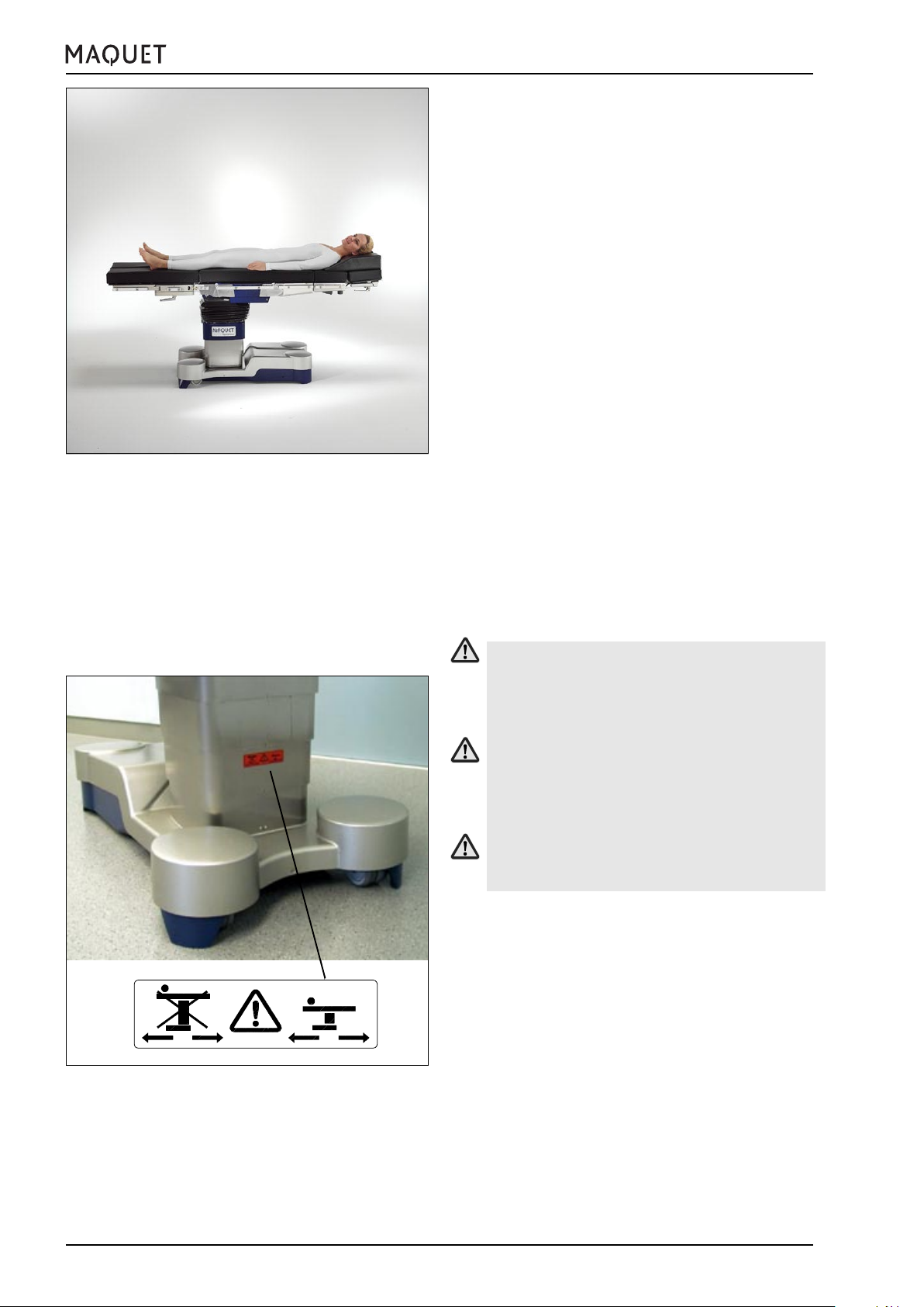
Fig.III-1: The preferred patient orientation
III. General description
III. General description
1. General features
In princliple, the operating table 1133.12 ALPHAMAXX
is suitable for the following surgical procedures:
• in the thorax and abdominal areas
• in the head area
• in gynaecology
• in urology
• in orthopaedics
If required, separate accessories can be attached to
the operating table.
The table top is subdivided into 6 sections:
• head plate (removable)
• upper back plate (removable)
• lower back plate
• seat plate
• split leg plates
The lower back, seat and leg plates are adjusted under
motor power.
The head plate and the upper back plate are adjusted
manually.
X-ray cassettes can be inserted underneath the back
plate.
The side rails are used to attach accessories.
1133.12B1/B3/F1/F3
NO
YES
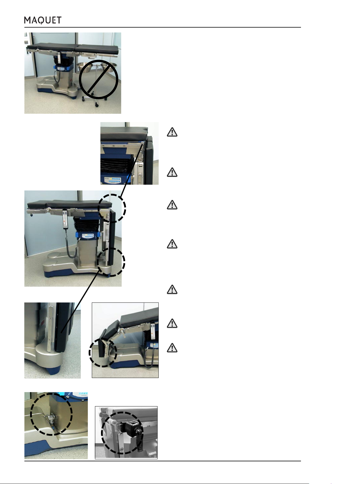
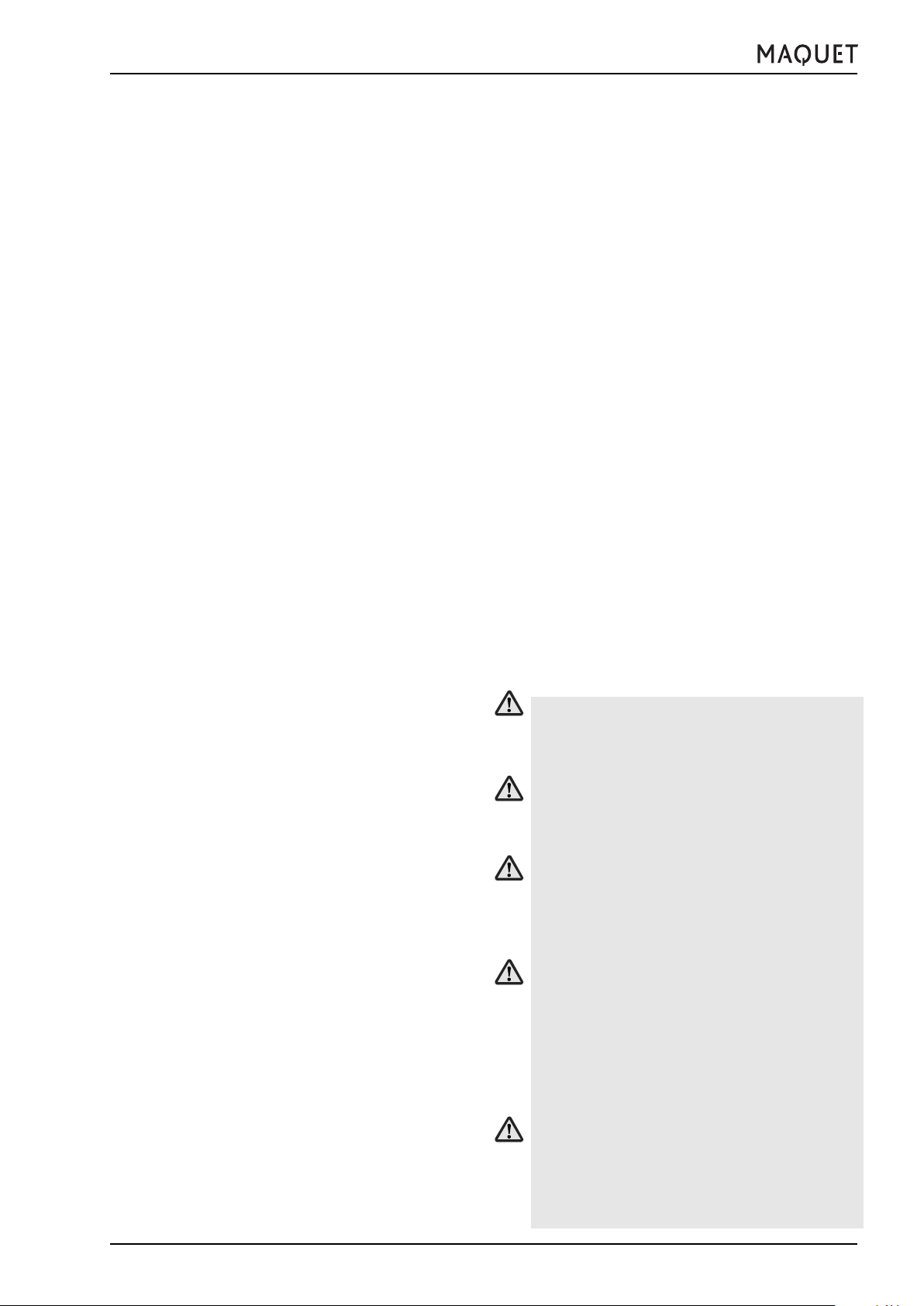
Fig.III-2: Warning sign for table top height
For patients weighing up to 135 kg (300 lb), place
the operating table on its castors (UNLOCK) only
up to the maximum table top height of 940 mm
(37 in)! The warning sign is not seen!
For patients weighing between 135 kg and max.
225 kg (300 - 500 lb), place the operating table
on its castors (UNLOCK) only when the table top
is in its lowest position.
Using the UNLOCK function for patient weights
exceeding 225 kg (500 lb) is not permissible.
1.1 Versions
Various versions of the operating table 1133.12 are available.
1133.12B1 Operating table incl. SFC padding and
standard side rails
1133.12B3 Operating table incl. SFC padding, standard side rails and autodrive in the base
1133.12F1 Operating table incl. SFC padding and US
side rails
1133.12F3 Operating table incl. SFC padding, US side
rails and autodrive in the base
The corded hand control, the IR transmitter, the charging station for the IR transmitter as well as head plates,
upper back plates and leg plates are to be ordered separately. The order numbers are listed in chapters VIII and
IX.
8
GA113312EN02
Page 9
1133.12B1/B3/F1/F3
III. General description
2. Control of functions
The electrohydraulic functions of the operating table can
be activated using one of the following control elements:
• Corded hand control (see 2.1)
• Override system = emergency operation(see 2.2)
or optionally via:
• IR remote control (see 2.3)
• Wall control panel (see 2.4)
• Foot switch (see 2.5)
The corded hand control and the IR remote control have
almost the same function buttons.
The override system is used only for emergency operation of the operating table.
The foot switch functions are: operating table height,
Trendelenburg/reverse Trendelenburg and another function (lateral tilt, longitudinal shift, back plate or leg plate
adjustment)
Note:
For safety reasons, only the following functions can
be used when the UNLOCK function is activated:
TRENDELENBURG and REVERSE TRENDELENBURG.
The sockets (14) for the corded hand control and
the foot switch are located on the override panel.
Note:
If the functions are controlled simulataneously by
more than one operating element, each movement
of the operating table is stopped immediately.
Hazard of operating table tipping over!
Make sure to remove any potential hindrances
before adjusting the operating table!
Hazard of damage during adjustments!
Do not place any objects on the operating table
base.
Hazard of pinching!
Do not reach under the table top or between the
table top components during adjustment procedures.
Injury hazard!
If the patient is not secured during transportation, when adjusting the operating table or when
positioning the patient (particularly when the slope
feature is used), then the patient could slip, uncontrolled, off the operating table. Always secure
the patient and maintain continuous observation.
GA113312EN02
Hazard of damage!
When not in use, hang up the corded hand control at the side rail of the operating table.
Make sure the cable of the hand control does not
get jammed when adjusting the operating table.
9
Page 10
III. General description
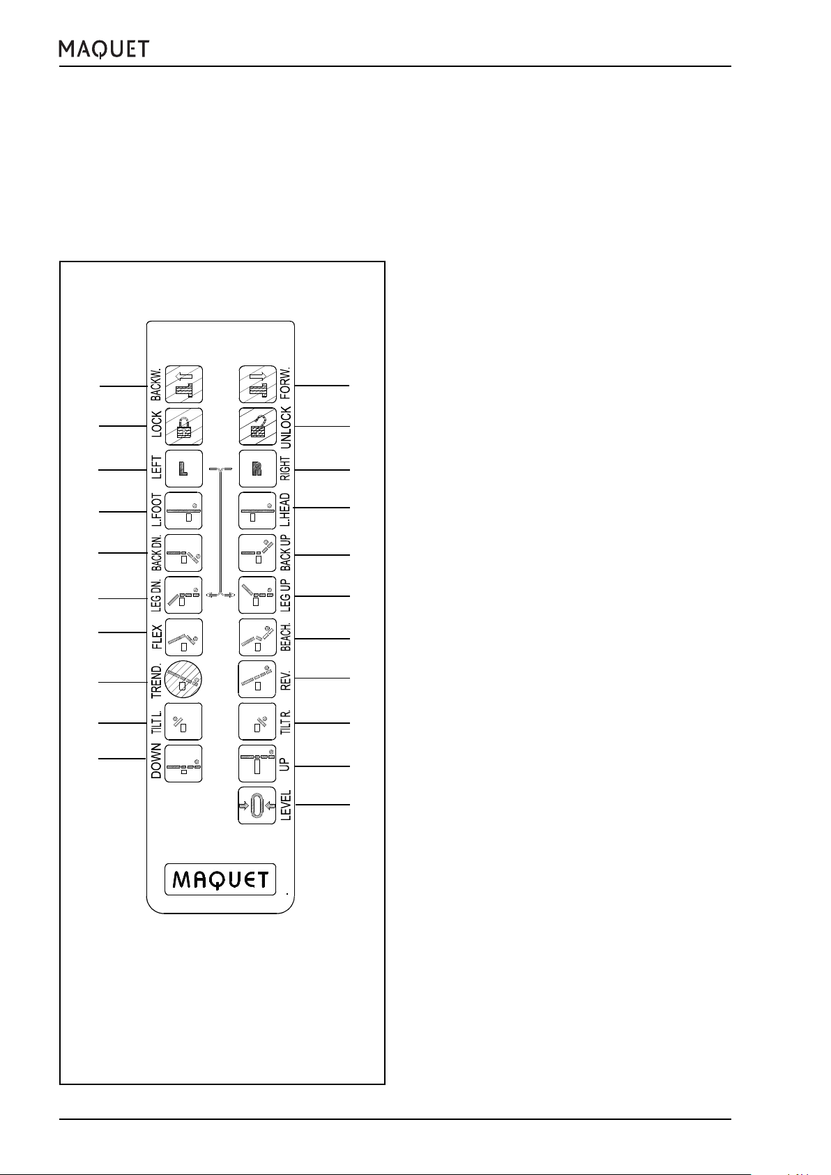
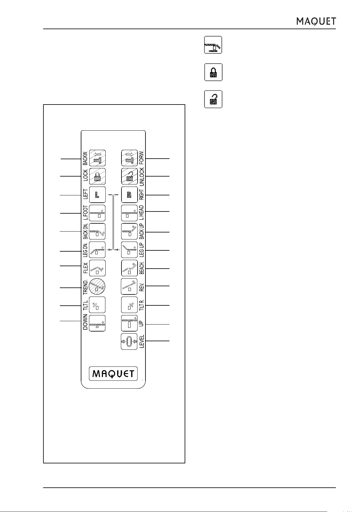
2.1 Corded hand control
The corded hand control is connected to the operating
table at one of the two sockets (14) (for simultaneous
connection of corded hand control and foot switch) on
the override panel (13). The electric motor-powered adjustments of the operating table can be made immediately by pressing down the corresponding function button.
1133.12B1/B3/F1/F3
v w
t
r
p
l
j
g
e
c
a
m
a) Table top
b) Table top
c) Tilt
d) Tilt
e) Trendelenburg position
f) Reverse Trendelenburg position
g)
Flex
Activates the functions
and
u
s
q
k
h
f
d
b
z
m) Slope (lower) back plate
w) Displace the operating table
reached to force the surgical field upward.
h)
Beach chair
Raises the back plate, moves the entire table
top into the Trendelenburg position and lowers the leg plates. The patient is moved into a
seated position.
j) Slope (both) leg plates
k) Slope (both) leg plates
l) Slope (lower) back plate
p) Shift table top
q) Shift table top
r) Adjust the left leg plate individually
The left leg plate can be controlled individually only in conjunction with the appropriate
function button for the desired movement, either downward (r+ j) or upward (r + k), under
two-button control.
s) Adjust the right leg plate individually
Analogous to the control for the left leg plate,
individually downward (s + j) or upward (s +
k), under two-button control.
t)
Lock
Press the LOCK button for at least 1 second:
the table will be immobilized automatically.
u)
UNLOCK
To unlock the operating table, press the UNLOCK button for at least 1 second, then the
castors will be extended automatically and
the table can be displaced.
v)
Autodrive in the base
Displace the operating table
ward the head end).
the foot end).
When displacing the operating table under
motor power, it must be guided with one hand.
down
up
to the left
to the right
position
(view from head end)
(view from head end)
back plate down
toward the foot end
toward head end
reverse Trendelenburg
until a flex position is
downward
upward
downward
upward
1133.12B2 (optional)
backward
forward
(to-
(toward
10
GA113312EN02
Page 11
1133.12B1/B3/F1/F3
III. General description
z) 0-position
Resets the lateral tilt, Trendelenburg/reverse
Trendelenburg, back plate and leg plate adjustments to the horizontal position. If the
function button z is pressed, the operating
table top will first reset the adjustments in the
following order: lateral tilt, Trendelenburg/reverse Trendelenburg, back plate. An acoustic
signal will indicate that these adjustments have
been reset. Release the function button z and
press once again to reset the leg plates to
the horizontal position; if the leg plates have
been adjusted individually, they will be positioned in parallel to one another.
Notes:
Manual adjustment functions such as those for the
upper back plate, head plate and leg plate abduction will not be affected by the IR remote control
(and, as a consequence, neither by the automatic
0-position function).
The transmission power for the IR remote control
ist sufficient to operate the draped operating table
even from a greater distance. If the desired adjustment is not executed by the operating table, even
though a function button is depressed completely,
then you should re-aim the hand control or move to
another position in the OR. In such cases the receiver is probably being blocked by a person’s body.
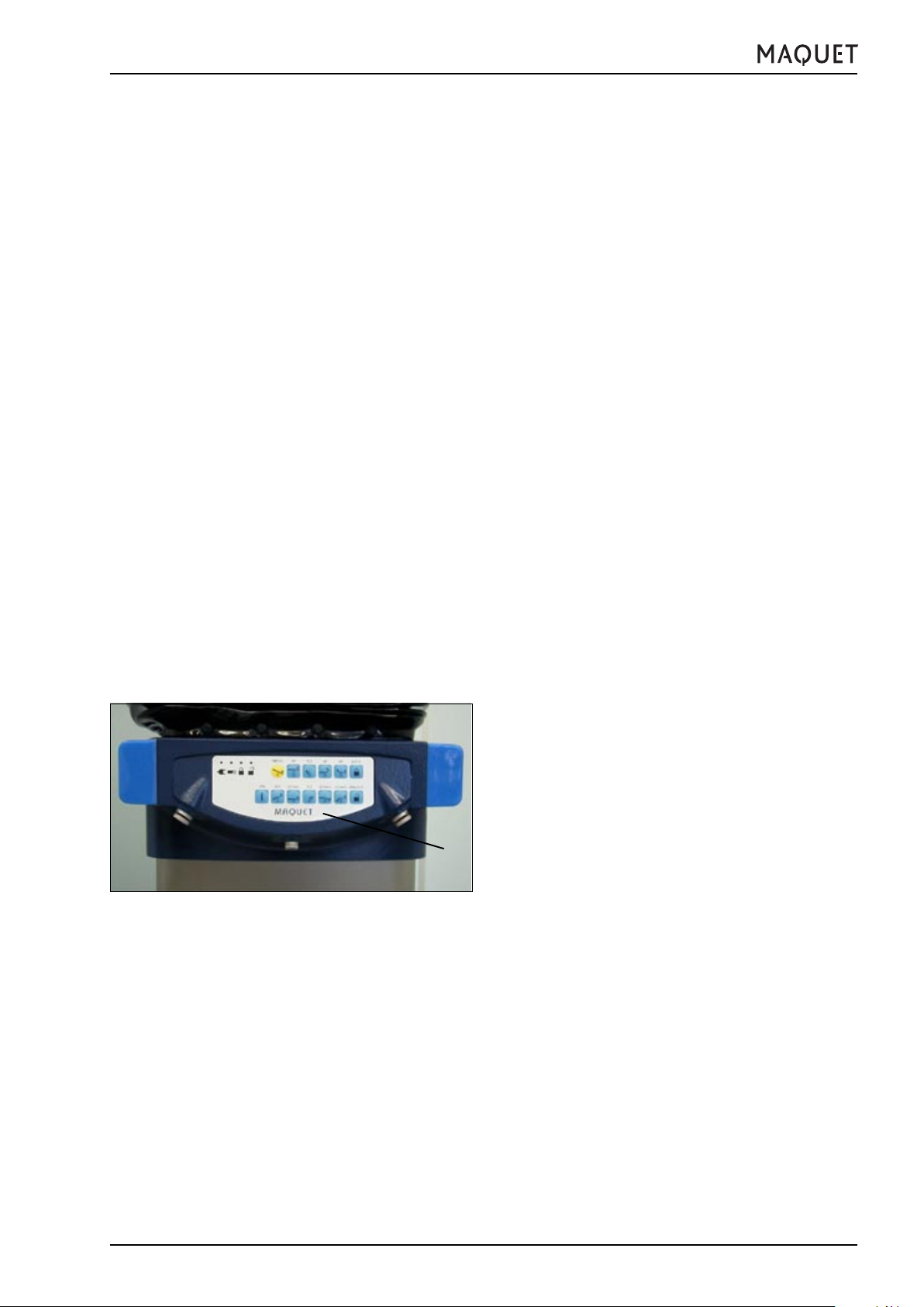
Fig.III-4: Override control panel
13
2.2 Override system = emergency operation
2.2.1 Override control panel
In case of a malfunction or if the hand control is defective, you can control the operating table functions via
the control panel (13) on the upper column casing (emergency operation).
Note:
Always press the ON button together with the desired function button.
Note:
If the operating table batteries are discharged, the
override system will only work when the operating
table is connected to the mains.
Note:
When using the override control panel, the collision
protection feature is not activated. Avoid extreme
adjustments - the combination of maximum Trendelenburg/reverse Trendelenburg position and maximum lateral tilt.
GA113312EN02
11
Page 12
AC
EGILN
III. General description
The functions of the override control panel are shown in
the following:
A) LED-Status indicators of the operating table
Note:
The status indicators are only active when the
corded hand control or the IR remote control is
switched on.
Description of the symbols from left to right:
• Mains connection: the green LED lights up
when the operating table is connected to the
mains.
• Battery charge level: the red LED flashes when
the operating table batteries have to be recharged as soon as possible.
• Operating table is immobilized: the green LED
lights up when the operating table is immobilized, i.e.
• Operating table castors are extended:
the red LED lights up when the operating table is on its castors and can be displaced, i.e.
UNLOCK
LOCK
activated.
activated.
1133.12B1/B3/F1/F3
DFHK
B
Fig.III-5: Override control panel buttons
MO
B) ON
switches the motor on and must be
pressed in addition to each function but-
ton
C) TREND
Table top into Trendelenburg position
D) REV.
Table top into reverse Trendelenburg
position
E) UP
Table top up
F) DOWN
Table top down
G) TILT
Lateral tilt to the left
12
H) TILT
Lateral tilt to the right
I) UP
Slope back plate upward
K) DOWN
Slope back plate downward
L) UP
Slope leg plate upward
GA113312EN02
Page 13
1133.12B1/B3/F1/F3
v w
t
r
III. General description
M) DOWN
N) LOCK
O) UNLOCK
2.3 IR remote control (optional)
The operating table can be equipped with an IR remote
control, as desired.
u
s
The required charging station for the IR remote control
is not included with the order no. 1133.91A0.
The layout of the function buttons for the operating table adjustments is the same on the corded hand control and the IR remote control apart from one exception:
Slope leg plate downward
Operating table immobilized
Operating table on its castors, can be displaced
m
q
k
h
f
d
b
z
There are no function buttons for the autodrive in the
base. For safety reasons, you can only activate this
function via the corded hand control.
Note:
When switching on the IR remote control, the LED
status indicators on the control panel on the operating table column are active (see chapter „Override
system“).
Note:
When using the IR remote control or the corded
hand control, the electronics generally avoid collisions with the floor or parts of the operating table.
If accessories with manual adjustment functions are
mounted, then it is not always possible to avoid
collisions.
p
l
j
g
e
c
a
Fig.III-6: IR remote control
GA113312EN02
13
Page 14
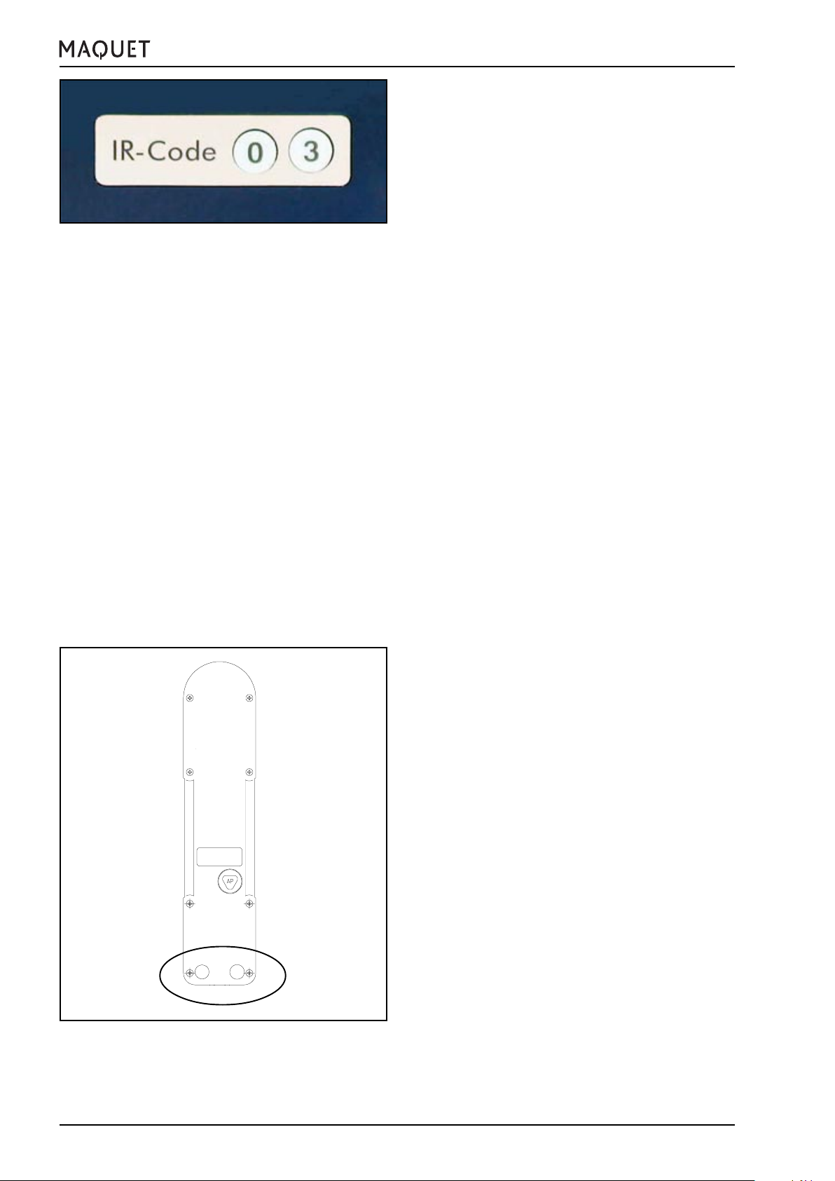
Fig.III-7: IR code
III. General description
2.3.1 IR system code
Every IR remote control is unequivocally assigned to an
operating table by way of the electronic encoding. The
operating table has the same system code as the associated IR remote control.
You can see from the label at the operating table column whether IR reception has been activated for this
operating table. If the IR code is crossed out, then the
infrared reception is blocked for the operating table.
The encoding for the operating table and the IR remote
control as well as activating/blocking the IR reception
are performed by authorized personnel.
The operating table and the associated IR remote control are marked by adhesive labels bearing the system
code which has been set:
• The adhesive labels are affixed to the operating table column next to the IR receiver.
• The adhesive labels are affixed to the back of the IR
remote control.
The two dot-shaped adhesive labels bear a number from
0 to 9 or a letter from A to F :
• left 0,1,2,...,A,B,...,F
• right 0,1,2,...,A,B,...,F
1133.12B1/B3/F1/F3
Fig.III-8: IR code
Examples of IR system codes which have been set:
Identification: 1 5
3A
C2
DA
Note:
The order of the identification letters/numbers is
singificant, i.e. the IR system code 4 B does not
equal B 4.
Note:
Always leave the IR remote control at the working
location for the associated operating table, since
the operating table can be adjusted only by using
this particular IR remote control.
Of course, the operating table can be adjusted via a
corded hand control or the override system at any
time, regardless of the IR remote control.
Note:
The transmission power of the IR remote control ist
0
3
sufficient to operate the draped operating table even
from a greater distance. If the desired adjustment is
not executed by the operating table, even though a
function button is depressed completely, then you
should re-aim the IR remote control or move to another position in the OR. In such cases the receiver
is probably being blocked by a person’s body.
14
GA113312EN02
Page 15
1133.12B1/B3/F1/F3
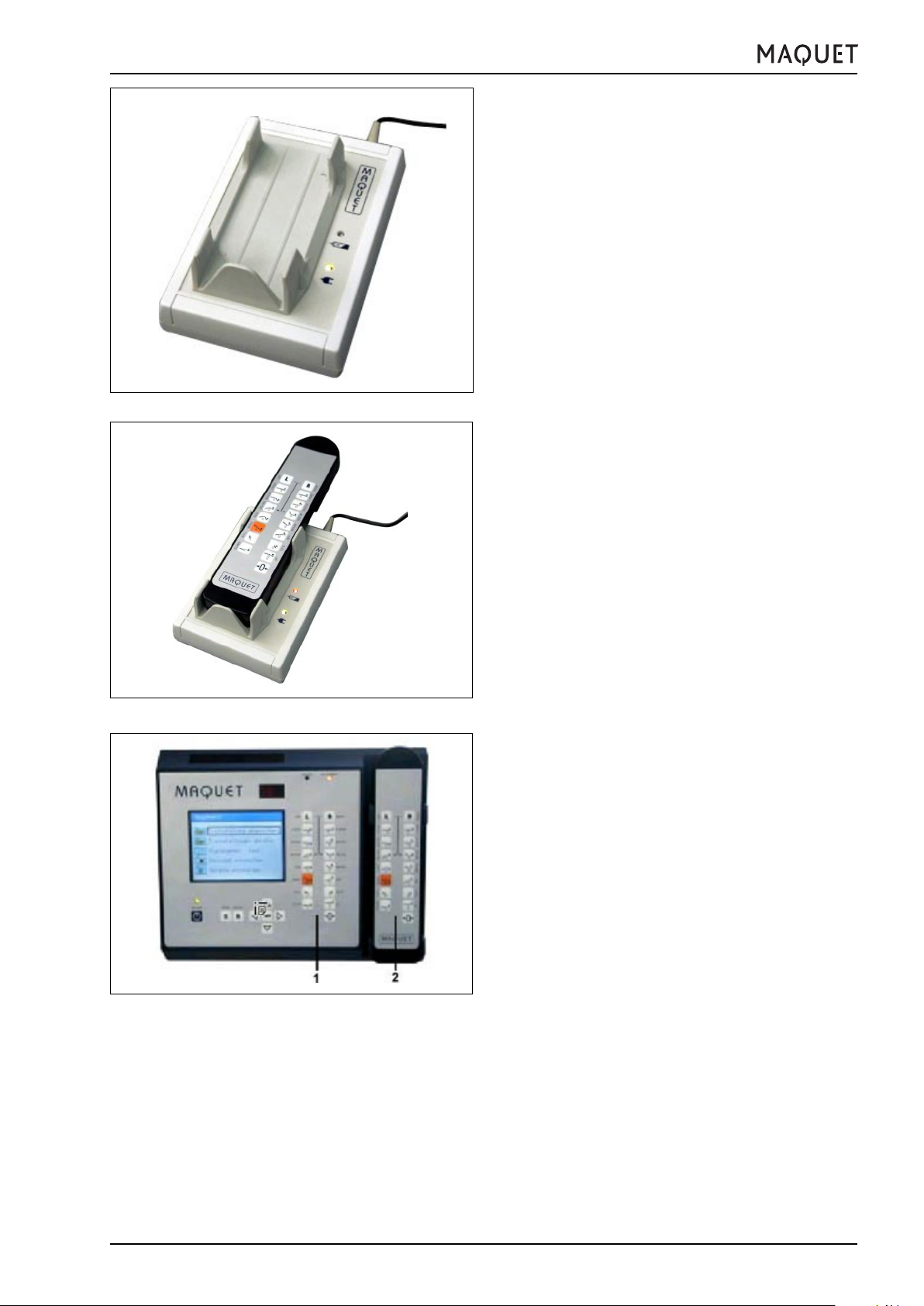
Fig.III-9: Charging station
III. General description
2.3.2 Charging station
Recharging the IR remote control:
• Connect the mobile charging station to the mains.
The green LED in the charging station indicates whether
the required supply voltage is available or not.
• Place the IR remote control in the charging station
as follows:
– Keypad visible, in the position for normal use,
i.e. the 0-position button (x) is located at the
bottom right
– the base of the hand control is in contact with
the lower limit stop of the holder.
Note:
The capacity of the rechargeable battery for the IR
remote control is sufficient to ensure several day’s
use of the operating table. Nevertheless, we recommend that you insert the hand control into the holder
of the charging station so that the battery is recharged overnight.
Fig.III-10: Charging station
Fig.III-11: IR wall control panel
2.4 Control via IR wall control panel
The desired adjustment functions of the operating table
can be controlled by means of the function buttons (1)
at the wall control panel or the separate IR hand control
(2).
Note:
The IR wall control panel can be mounted to the
wall at a later date.
For further information please refer to the operating
instructions GA115095GBxx.
GA113312EN02
15
Page 16
14
Fig.III-12: Foot switch
III. General description
2.5 Control via foot switch 1009.81DX (optional)
14
Connect the foot switch to one of the two sockets (14)
at the column head.
Three functions each can be activated using the following foot switch versions:
1009.81D0 Foot switch with the functions:
1009.81D1 Foot switch with the functions:
1009.81D2 Foot switch with the functions:
1009.81D3 Foot switch with the functions:
Note:
Observe the operating instructions for the foot
switch.
1133.12B1/B3/F1/F3
height, Trendelenburg/rev. Trendelenburg, back plate
height, Trendelenburg/rev. Trendelenburg, lateral tilt
height, Trendelenburg/rev. Trendelenburg, leg plates
height, Trendelenburg/rev. Trendelenburg, longitudinal shift
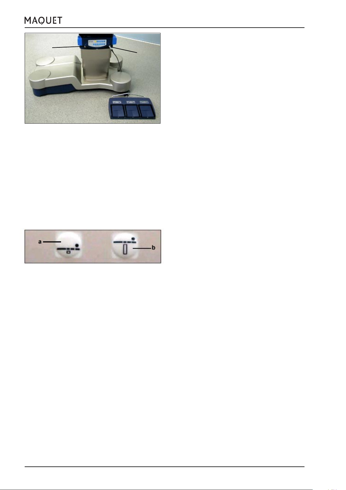
Fig.III-13: „Neurolock“ function
2.6 „Neurolock“ function
If requested, the MAQUET service personnel can set
the „Neurolock“ function at the operating table.
This function avoids adjustments of the table position
due to unintentional actuation of the buttons on the hand
control.
a+b) The „Neurolock“ function can be unlocked by
pressing simultaneously the buttons „table top
down“ (a) and „table top up“ (b) on the control
module. The operating table can now be adjusted.
If no further buttons on the control module are
actuated for approx. 8 seconds, then the
„Neurolock“ function will be activated again. Adjusting the operating table again is only possible
after actuating simultaneously the „table top
down“ (a) and „table top up“ (b) function buttons.
Note:
The „table top down“ and „table top up“ functions
cannot be actuated simultaneously using the foot
switch 1009.81X0.
Use an IR hand control or a corded hand control to
unlock the „Neurolock“ function.
16
GA113312EN02
Page 17

1133.12B1/B3/F1/F3
III. General description
3. Table top
3.1 General features
The table top 1133.12 has been designed to meet the
requirements of various surgical disciplines. Selecting
from a variety of modules lets you adapt the geometry
of the table top to accommodate the individual patient
height.
The table top is divided into a maximum of 6 sections,
depending on the type of leg plate and upper back plate
module selected.
• Head plate
• Upper back plate (extension segment)
• Lower back plate
• Seat plate
• Leg plates
The table top is equipped with a motor-powered
longitudinal shift feature through 230 mm, and motorpowered adjustment functions for the back plate and leg
plates. Furthermore the mounting sockets for the leg
plates automatically detect whether one-piece
components have been installed, thus increasing
reliability and safety in use. Depending on the application,
the adjustment ranges for the accessories mounted at
the leg plate mounting point may be restricted. Please
refer to the operating instructions for the accessory in
question.
Attaching different back plate modules at the lower/
upper back plate mounting point enables positions
perfectly suited to the patient and more favourable
functional working conditions for the surgical team and
the procedure. Guide rails for X-ray cassettes are
located underneath the back plate. The side rails are
used to attach accessories. Various head positioning
accessories can be mounted at the head end of the back
plate modules instead of the head plate (see chapter V,
Patient positioning).
GA113312EN02
Note:
According to the IEC 60601-1 international standard, the operating table is designed for safe handling of a patient weight of 450 kg (1000 lb). When
using accessories, the maximum load may be restricted. Please observe chapter VIII List of accessories.
17
Page 18

III. General description
3.2 Mechanical adjustments
3.2.1 Mount / remove the head plate
Note
Use and handling are described in detail in the operating instructions for this product.
Note
The head plate adapter 1130.81A0 is required to
mount head plates at the back plate mounting point.
3.2.1.1 Mount the head plate using the head plate
adapter 1130.81A0.
Note
The head plate adapter consists of a left and a right
part. Please observe the markings L and R.
If the adapters are mixed up, the distance of the
mounting sockets is not correct.
1133.12B1/B3/F1/F3
A
B
Fig.III-14: Mount the head plate adapter
C
A
B
Mount the head plate
⌧ Insert the pins of the two head plate adpaters
1130.81A0 (A) in the sockets (B) at the back plate
mounting point, up to the stop.
⌧ Insert the head plate pins (C) into the mounting
sockets (D) at the front of the table top, up to the
stop.
D
Fig.III-15: Mount the head plate
18
D
GA113312EN02
Page 19
1133.12B1/B3/F1/F3
III. General description
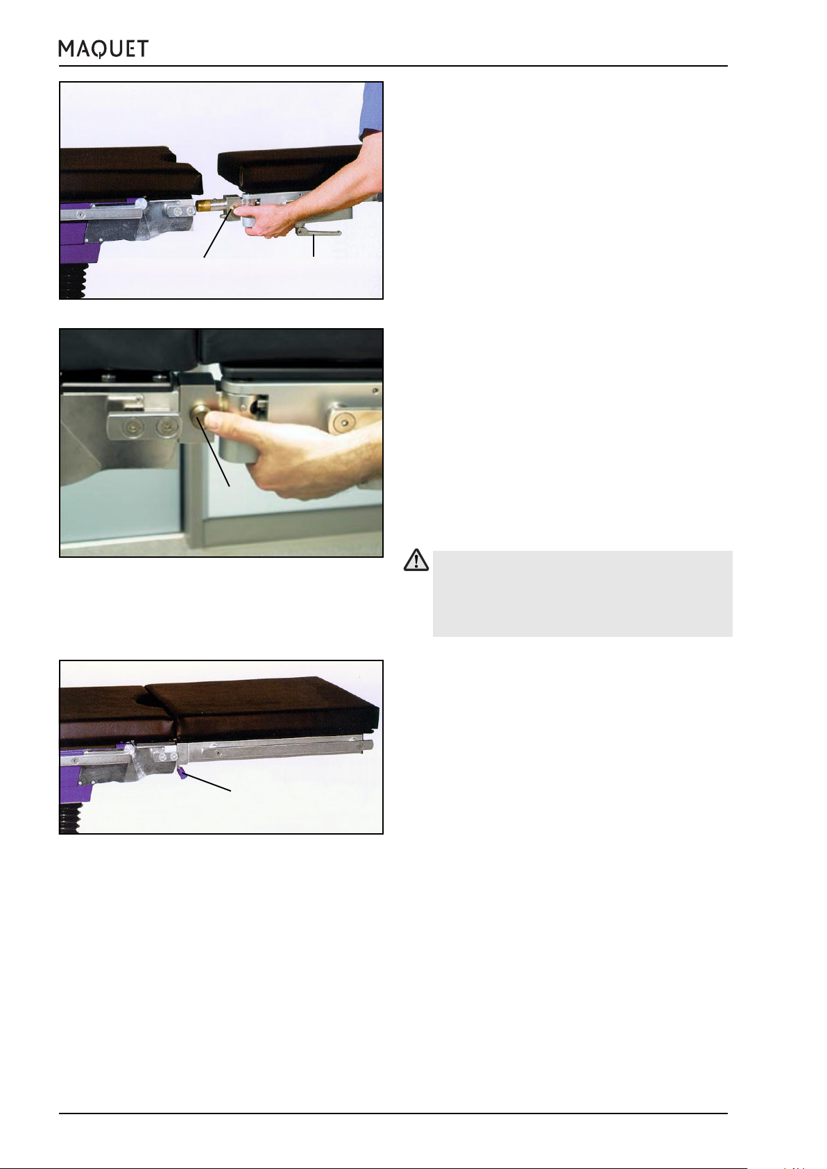
⌧ Tighten the locking screws (E).
⌧ Pull on either side of the seat plate extension to
ensure that it is properly secured.
E
Fig.III-16: Mount and secure the head plate
E
C
E
Remove the head plate
⌧ Loosen the locking screws (E).
⌧ Remove the head plate (C).
⌧ Remove the two head plate adapters 1130.81A0.
Fig.III-17: Remove the head plate
GA113312EN02
19
Page 20

III. General description
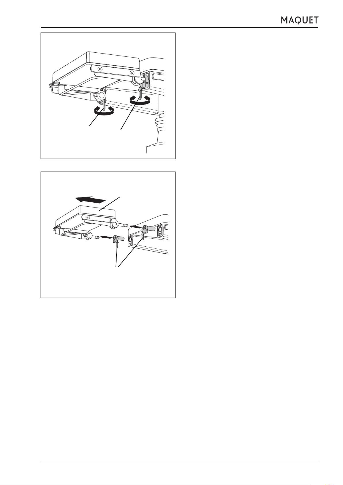
3.2.1.2 Mount / remove the joint adapters 1131.82A0
Note
The joint adapter consists of a left and a right part.
Please observe the markings L and R.
If the joint adapters are mixed up, they cannot be
used since the eccentric levers will point to the middle of the table top.
Mount the joint adapter
⌧ Insert the left joint adapter 1131.82A0 (L) and the
right joint adapter 1131.82A0 (R) with their pins fully
L
1
R
in the sockets (A) of the back plate mounting point,
at the front of the table top.
1133.12B1/B3/F1/F3
A
Fig.III-18: Insert the joint adapter
L
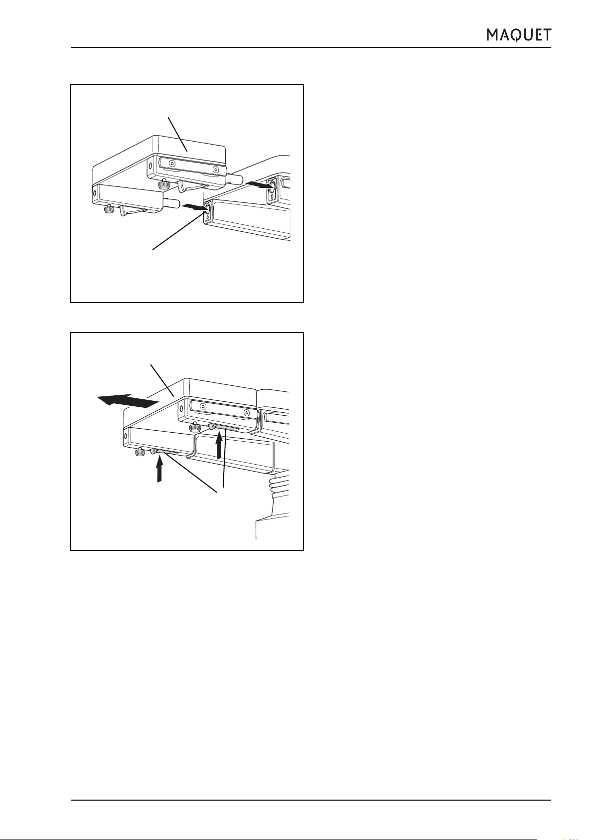
Fig.III-19: Swivel the joint adapters downward
R
⌧ Swivel the joint adapters (L) and (R) downward in the
direction of the arrows, up to the stop.
20
GA113312EN02
Page 21

1133.12B1/B3/F1/F3
Fig.III-20: Check to ensure proper attachment
III. General description
⌧ Pull on the adapter to ensure that it is properly
secured.
Remove the joint adapters
R
L
Fig.III-21: Remove the joint adapters
⌧ Swivel the joint adapters (L) and (R) upward in the
direction of the arrows, up to the stop.
⌧ Pull out the joint adapters (L) and (R).
GA113312EN02
21
Page 22

A
B
C
1
Fig.III-22: Remove the back plate
III. General description
3.2.1.3 Change out accessories at the joint adapter
1131.82A0
⌧ If a back plate (A) is already mounted: Hold the back
plate.
⌧ On either side:
Press on the safety push-button (B) and open the
eccentric lever (C).
⌧ Raise the back plate (A) until it is in an almost vertical
position (approx. 75°) and remove it from the joint
adapter mounting point.
1133.12B1/B3/F1/F3
Fig.III-23: Mount the back plate
⌧ Insert the other back plate (D) from above, in an
almost vertical position (approx. 75°), in the joint
D
E
adapter mounting point, lower it until it is in the
desired position and hold it.
⌧ On either side:
Retighten the eccentric lever (E).
22
GA113312EN02
Page 23
1133.12B1/B3/F1/F3
A
B
Fig.III-24: Mount the extension segment
III. General description
3.2.2 Extension segment 1131.31B0/F0
The table top is extended to position taller patients or
to optimize the patient position.
Mount the extension segment
⌧ If necessary, remove the head plate
⌧ Insert the pins of the extension segment (A) in the
mounting sockets (B) at the front of the table top, up
to the stop.
The extension segment is locked automatically.
⌧ Pull on either side of the seat plate extension to
ensure that it is properly secured.
A
C
Fig.III-25: Remove the extension segment
Remove the extension segment
⌧ Press the two levers (C) against the extension
segment.
⌧ Remove the extension segment (A) without binding.
GA113312EN02
23
Page 24
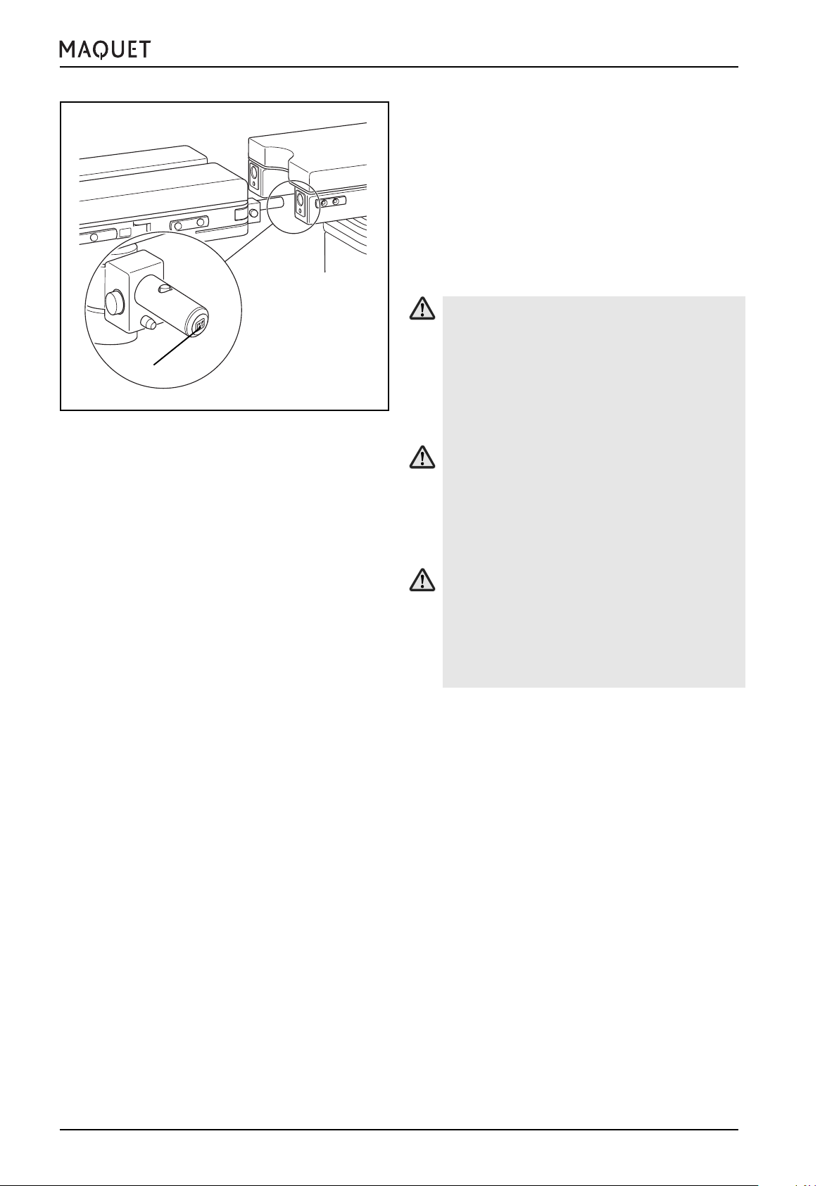
A
Fig.III-26: Accessory recognition feature
III. General description
3.3 Collision protection at the leg plate mounting point
The table top is fitted with an accessory recognition
feature at the leg plate mounting point. When using
encoded leg plate accessories, this feature recognizes
the accessories and avoids collision with the operating
table or the floor during leg plate adjustment.
Encoded accessories are fitted with a “code plug” (A) at
the front of the mounting pin.
Accessories which are not encoded at the mounting pin
can be used at the leg plate mounting point; however,
there is no collision protection when making adjustments.
Injury hazard!
It is possible to use accessories which are not
encoded at the leg plate mounting point: this may,
however, result in collisions during certain adjustment procedures.
Observe the movement during the adjustment
procedure and be sure to avoid any collision.
1133.12B1/B3/F1/F3
Injury hazard!
Additional accessories mounted at the side rails
will not be recognized by the collision protection
feature.
Observe the movement during the adjustment
procedure and be sure to avoid any collision.
Injury hazard!
A leg plate which is mounted in addition at the
seat plate extension will not be recognized by
the collision protection feature.
Observe the movement during the adjustment
procedure and be sure to avoid any collision.
Functional sequence
⌧ Press and hold any button.
The collision protection is activated and will stop
the downward movement in time.
⌧ Release the button.
24
GA113312EN02
Page 25

1133.12B1/B3/F1/F3
III. General description
3.3.1 Seat plate extensions
The seat plate extension is suitable for use during procedures in gynaecology and urology.
Seat plate extension 1133.55BC
• To mount or remove the seat plate extension, actuate the release lever (A) and insert the seat plate
extension in the mounting sockets up to the stop or
remove it.
• The seat plate extension cannot be adjusted.
A
Fig.III-27:Seat plate extension 1133.55BC
A
B
Fig.III-28: Mount the seat plate extension
Seat plate extension 1131.55B0/F0
Mount the seat plate extension
⌧ If necessary, remove the leg plate.
⌧ Insert the pins of the seat plate extension (A) in the
mounting sockets (B) at the front of the table top, up
to the stop.
The seat plate extension is locked automatically.
⌧ Pull on either side of the seat plate extension to
ensure that it is properly secured.
The seat plate extension can be adjusted.
Remove the seat plate extension
A
C
Fig.III-29: Remove the seat plate extension
GA113312EN02
⌧ Press the two levers (C) against the seat plate
extension.
⌧ Remove the seat plate extension (A) without binding.
25
Page 26
10
Fig.III-30: Mount the split leg plate
III. General description
3.3.2 Leg plates Split leg plate 1133.53BC
• To mount the split leg plates, press the push-button
(10) and insert the leg plate pins in the mounting
sockets, up to the stop (Abb. III-30).
• The leg plate is locked as soon as the push-button
is released (10) (Fig.III-31).
• The slope of the leg plate is adjusted
electrohydraulically by means of the control mod-
9
ule.
• To abduct the leg plate, open the eccentric lever (9)
and set the desired abduction angle.
• Retighten the eccentric lever after making the adjustment.
• A dual-pivot joint is used to abduct the leg plates
1133.53 so that on the one hand the surgeon has
access to the patient’s body from the foot end while
at the same time the patient’s leg is given sufficient support.
1133.12B1/B3/F1/F3
10
Fig.III-31: Unlock the leg plates
A
Fig.III-32: Mount / remove the single-section leg plate
• To remove the leg plate, press the push-button (10)
and pull the leg plate out of the mounting sockets.
Before setting the leg plates in the flat and horizontal position (0-position), be sure to observe
that they are not positioned one on top of the
other.
Collision hazard! Injury hazard!
Single-section leg plate 1133.58BC
• To mount or remove the single-section leg plate,
acuate the release lever (A) and insert the leg plate
in the mounting sockets up to the stop or remove it.
The single-section leg plate is suitable for surgical
procedures in orthopaedics ans vascular surgery
where the patient’s legs are to be X-rayed. The slope
of the leg plate is adjusted electrohydraulically by
means of the control mudule.
26
GA113312EN02
Page 27

1133.12B1/B3/F1/F3
III. General description
3.4 Table top padding
The operating table top is supplied with table top plates
and SFC pads secured with Velcro straps.
3.5 Accessories
Mount only the accessories listed in chapter VIII.
Do not use non-original accessories which affect the
longitudinal geometry of the table top without first consulting with MAQUET.
Accessories which are mounted on the side rails of the
operating table provided for this purpose should also be
drawn exclusively from the MAQUET line of accessories. When developing MAQUET accessories, close
attention is paid to careful harmonization with the
MAQUET operating tables. This means that when the
accessory is used for its intended purpose, the maximum possible safety for patients and staff will be attained.
Accessories (to be mounted on the side rails) which
are made by other manufacturers must be particularly
carefully examined to ensure that they do not represent
a hazard to the patient and the staff or to the operating
table (due to possible collisions). Particularly accessory units with high weights or long lever arms (such as
hand operating tables, retractor systems etc.) must be
expressly permitted by MAQUET.
Injury hazard!
Do not use worn or damaged accessories!
Injury hazard!
Make sure to fasten the table top accessories
properly!
Injury hazard!
Collisions between accessories, the operating
table and the patient can occur when adjusting
or displacing the operating table.
Observe the adjustment procedure and avoid collisions.
GA113312EN02
27
Page 28

III. General description
4. Autodrive in the base
The operating table version 1133.12B3/F3 is equipped
with an autodrive in the base. The operating table will
start moving slowly and will slow down softly after releasing the function button (i or k).
i) BACKW.
k) FORW.
To move the operating table, proceed as follows:
• Remove the mains cable from the operating table
• Fully extend the operating table castors (press UN-
LOCK button)
• Guide the operating table with at least one hand
• Press function button (v or w) and the operating ta-
ble will move in the selected direction.
• Release function button (v or w) and the operating
table will gently brake until it stops.
1133.12B1/B3/F1/F3
Move the table backward in the longitudinal
direction
Move the table forward in the longitudinal
direction
Fig.III-33:Overide control panel
Note:
If the LEDs for the LOCK and UNLOCK functions
are flashing, press the UNLOCK button.
Guide the operating table with at least one hand
during displacement.
Note:
When moving the operating table, do not press the
override system buttons since this will cause several functions to be activated simultaneously and
involve the hazard of injury or collision with potential
hindrances.
Note:
The operating table can only be moved laterally if
you have not activated the BACKW. or
FORW.functions!
28
GA113312EN02
Page 29

1133.12B1/B3/F1/F3
IV. Use of the operating table
IV. Use of the operating table
1. General
The operating table’s electrical conductivity has
to be checked once a year! This check should
be performed only by trained servicing personnel.
Note:
Connect the operating table to the potential equalization system in the OR during the surgical procedure (see DIN VDE 0100 standard, Part 1).
For this purpose, connect the potential equalization pin with the cable to a potential equalization
point in the OR, next to the patient.
A potential euqlization cable (5 m) with connectors
at both ends is included in the scope of supply of
the operating table.
2. Operation on battery power
When operating the table with the integrated batteries
with no connection to the mains supply, the operating
table meets the requirements of the Class AP Test for
Anaesthesiological Operation. It may be used in areas
subject to explosion hazard, zone M.
Battery operation of the table is always preferable to
operation on mains power.
Th capacity of the fully charged batteries allow approx.
one week’s use of the operating table, depending on
how often adjustments are made.
If the charge level of the batteries drops below a minimum permissible value, this is indicated by the red operating table status indicator LED when the operating
table is switched on.
Note:
At less than 10% charge the operating table will
shut down automatically.
Recharge the batteries
Discharged batteries will attain 90% of their charging
capacity after approx. 5 hours (100% after approx. 10
hours).
The batteries are automatically recharged as soon as
the operating table is connected to the mains by means
of the mains cable.
GA113312EN02
29
Page 30
IV. Use of the operating table
Note:
We recommend to recharge the batteries overnight,
but at least every 2 days, even if „low charge level“
of the batteries has not been indicated yet.
Regular recharging of the batteries will ensure sufficient battery power for the daily OR programme. It
will also serve to prolong the useful life of the batteries.
1133.12B1/B3/F1/F3
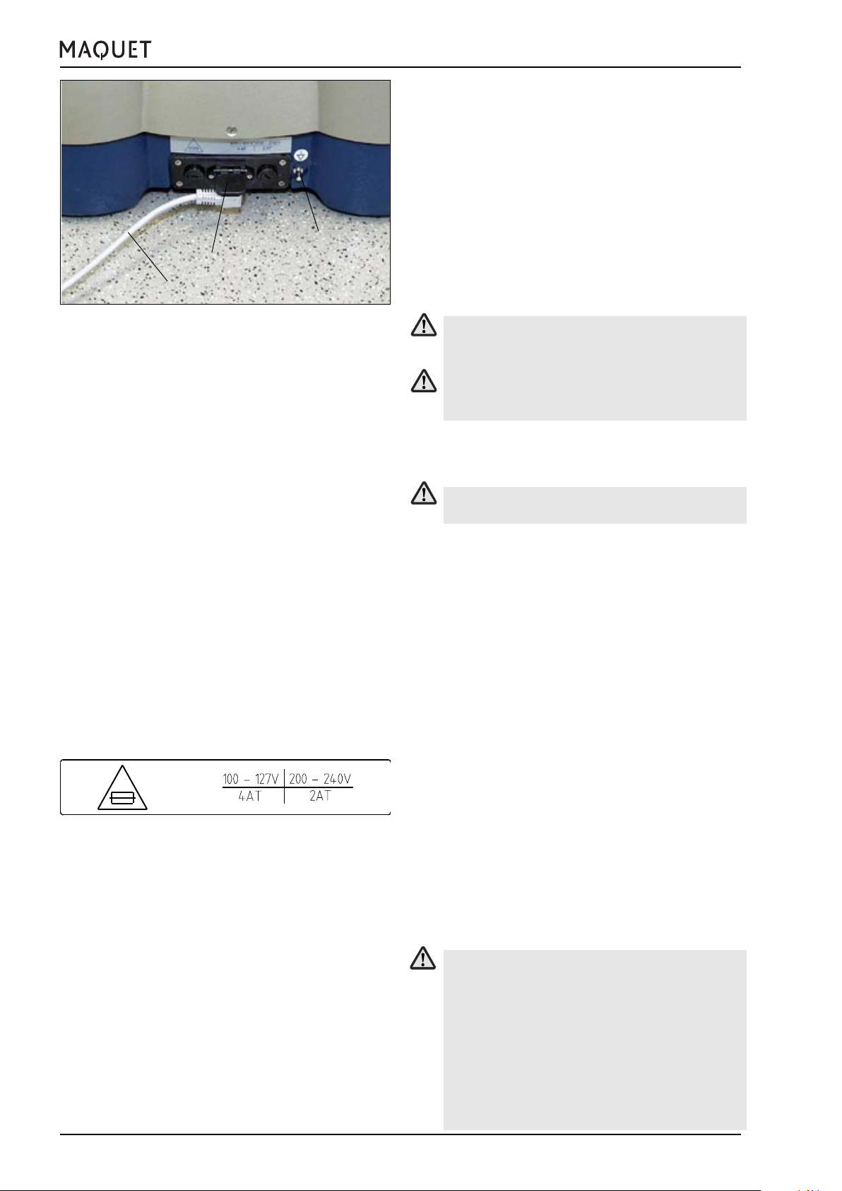
Potential equalization
Socket for mains cable
Mains cable
Fig.IV-1: Operating table connections
3. Operation on mains power
The batteries are automatically recharged as soon as
the operating table is connected to the mains by means
of the mains cable.
There is no explosion protection while recharging the batteries or when the operating table is
on mains power.
The operating table is disconnected from the
mains by means of the mains plug.
Connect the operating table to the mains by means of
the mains cable.
When connecting or removing the mains cable,
observe the correct order of the procedure!
• When connecting the mains cable, first of all
connect the operating table and then connect
the plug to the mains.
• When disconnecting the mains cable, first of
all pull the plug out of the socket and then
remove the cable from the operating table.
Fig.IV-2: Fuses
Note:
Damaged cables must be replaced immediately.
When replacing fuses, please note:
1. Unplug the operating table
2. Unscrew the two fuse holders located on the right
and left next to the socket for the mains connection using a coin or a large screw driver.
3. Insert the appropriate fuse according the the table
opposite
4. Reinsert the fuse holders
4. HF surgery, use of defibrillators
In the field of HF surgery and when using defibrillators,
be absolutely sure to observe the following safety instructions:
Hazard of burns!
When using HF surgical equipment, defibrillators
and defibrillation monitors, make sure to avoid
that the patient comes into contact with metal
parts of the operating table, the table tops or the
accessories. Also make sure to avoid that the
patient is lying on moist underlays or sheets on
the conductive pads.
Be absolutely sure to comply with the manufacturers operating instructions!
30
GA113312EN02
Page 31
1133.12B1/B3/F1/F3
V. Patient positioning
V. Patient positioning
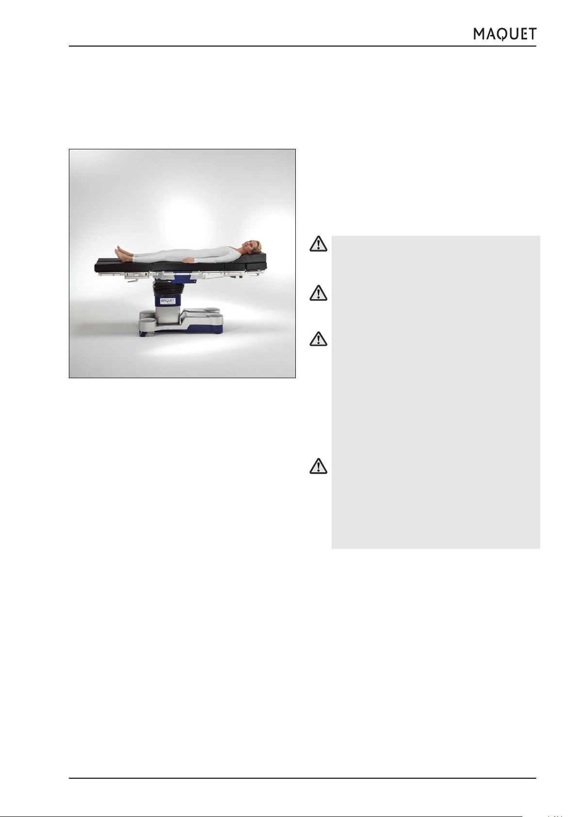
1. General
The 1133.12 modular operating table offers the possibility to use various modules as the back plate, thus providing advantages for adaptation of the patient position
to different surgical disciplines.
Note:
The NORMAL patient orientation is preferable to
the REVERSE patient orientation. In the NORMAL
patient orientation the patient’s head is lying above
the long end of the operating table base (see
sketch).
In accordance with generally accepted hygiene
standards, the operating table top is to be covered with surgical drapes during use.
Observe the prescribed orientation for the patient.
Never position the patient’s upper part of the body
on the leg plate.
Fig.V-1: The preferred patient orientation
Injury hazard!
Risk of injury due to the operating table tipping
over or material breaks when using non-approved
accessories. The patient positions vary, depending on the patient weight (see sketches in chapter V, Patient positioning) and the operating table accessories which may be employed (see
Accessories list, chapter VIII).
Observe the specifications for positioning the
patient according to his/her weight.
Injury hazard!
If the patient is not secured during transportation, when adjusting the operating table or when
positioning the patient (particularly when the slope
feature is used), then the patient could slip, uncontrolled, off the operating table. Always secure
the patient and maintain continuous observation.
GA113312EN02
31
Page 32

Fig.V-2: Patient position
V. Patient positioning
Injury hazard!
If the operating table is not wide enough to enable an ergonomic patient position, then the patient may be injured.
The table width extenders (1001.75A0 / 76A0)
may be mounted on the side rails of the operating table to enable ergonomic patient positioning.
Only one infusion stand (1009.01C0), one anaesthesia screen (1002.57A0), one wristlet
(1002.24C0) and one arm protector (1002.25A0)
may be mounted to the table width extenders
(1001.75A0 / 76A0).
When positioning the patient, be sure to observe
that the patient is lying above the centre of the
column in the lateral direction (see sketch).
Injury hazard!
It is not permissible to mount another table width
extender to a table width extender 1001.75A0/
76A0.
1133.12B1/B3/F1/F3
Injury hazard!
The nursing staff must ensure the patient is properly positioned and observe the patient’s condition in order to avoid endangering the patient’s
respiratory system, nerve pathways and circulatory system.
Injury hazard!
Keep the patient under continuous observation
when adjusting the knee crutches.
Hazard of tipping over!
Immobilize the operating table prior to transferring the patient! Press the LOCK button!
Note:
After standstills, actuate the operating table functions to check proper functioning before positioning
the patient.
Press the function buttons height up/down, Trendelenburg/reverse Trendelenburg, lateral tilt right/left,
back palte up/down, leg plates up/down for two to
three seconds each. Finally, press the 0-position
button (z) to align the operating table horizontally.
The functions of the corded hand control are described on page 9.
32
Note:
Depending on the patient weight, the speed of the
motor-powered adjustment and displacement functions will change.
When lowering the table while a heavy patient is
lying on the table top, the speed of downward movements will slighly increase.
The adjustment speed will be reduced during upward movments.
GA113312EN02
Page 33

1133.12B1/B3/F1/F3
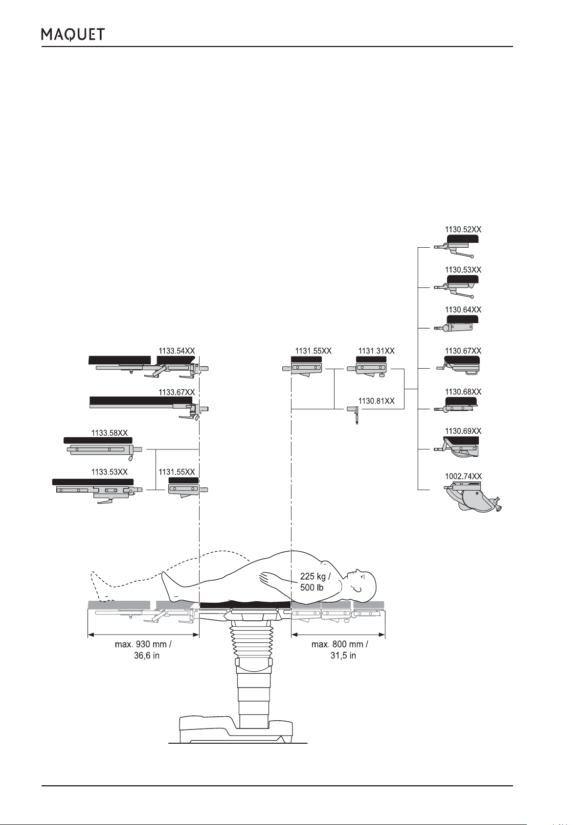
2. Positioning a patient weighing between 225 kg and 450 kg (500 lb - 1000 lb)
2.1 Approved accessories Injury hazard!
The accessories which are mounted may not exceed the maximum length as specified in the sketch below.
For further accessories, please refer to the accessories list in chapter VIII.
•
We recommend to use the extension segment 1131.31xx in conjunction with the head plate 1130.67xx to
extend the table top at the head end by 540 mm (21.3 in).
• Leg plates: The abductable leg plate 1133.53xx (max. length 675 mm) as well as the single-section leg plate
1133.58xx are approved.
• Accessories mounted on the side rails
1001.44D0 Arm posturing device 450 mm long
1001.75A0 Table width extender 100 x 300 mm
1001.76A0 Table width extender 100 x 200 mm
1002.25A0 Arm protector
1001.85B0 Foot plate
1001.86A0/B0 Split foot plate
2.2 Operating table immobilized (LOCK) Hazard of operating table tipping over!
Injury hazard due to the operating table tipping over when extending the operating table castors (UNLOCK).
The operating table must always be immobilized (LOCK) for patient weights exceeding 225 kg.
V. Patient positioning
Injury hazard!!
Injury hazard due to the patient slipping off the operating table during unrestricted use of adjustment functions.
Therefore, restrict the adjustment functions as follows for patient weights exceeding 225 kg:
• Longitudinal shift not permissible
• maximum slope (Trendelenburg/reverse Trendelenburg) ±10°
• maximum tilt (left/right) ±5°
• maximum back plate slope ±10°
• maximum leg plate slope ±10°
The adjustment functions are restricted in the interest of patient safety.
Injury hazard!!
If the patient is not positioned correctly, then the operating table may tip over.
Patients weighing more than 225 kg may be positioned in the NORMAL patient orientation only.
GA113312EN02
33
Page 34

V. Patient positioning
1133.12B1/B3/F1/F3
Fig. V-3: NORMAL patient orientation 450 kg (1000 lb) max. patient weight LOCK
3. Positioning a patient weighing between 135 kg and 225 kg (300 lb - 500 lb)
3.1 Approved accessories
Injury hazard!
The accessories which are mounted may not exceed the maximum length as specified in the following
sketch.
For further accessories, please refer to the accessories list in chapter VIII.
• We recommend to use the extension segment 1131.31xx in conjunction with the head plate 1130.67xx to
extend the table top at the head end by 540 mm (21.3 in).
• Accessories mounted on the side rails
1001.44D0 Arm posturing device 450 mm long
1001.75A0 Table width extender 100 x 300 mm
1001.76A0 Table width extender 100 x 200 mm
1002.25A0 Arm protector
1001.85B0 Foot plate
1001.86A0/B0 Split foot plate
3.2 Operating table not immobilized (UNLOCK)
Hazard of operating table tipping over!
If the patient is not positioned correctly, then the operating table may tip over when extending the operating
table castors (UNLOCK).
The patient must be positioned according to Fig. V-4 and Fig. V-5 and the operating table must be set to its
lowest position before extending the operating table castors (UNLOCK).
34
GA113312EN02
Page 35

1133.12B1/B3/F1/F3
3.2.1 NORMAL patient orientation / operating table not immobilized (UNLOCK)
V. Patient positioning
Fig. V-4: NORMAL patient orientation 225 kg (500 lb) max. patient weight UNLOCK
GA113312EN02
35
Page 36

V. Patient positioning
3.2.2 REVERSE patient orientation / operating table not immobilized (UNLOCK)
1133.12B1/B3/F1/F3
Fig. V-5: REVERSE patient orientation 225 kg (500 lb) max. patient weight UNLOCK
36
GA113312EN02
Page 37

1133.12B1/B3/F1/F3
3.3 Operating table immobilized (LOCK)
3.3.1 NORMAL patient orientation / operating table immobilized (LOCK)
V. Patient positioning
Fig. V-6: NORMAL patient orientation 225 kg (500 lb) max. patient weight LOCK
GA113312EN02
37
Page 38
V. Patient positioning
3.3.2 REVERSE patient orientation / operating table immobilized (LOCK)
1133.12B1/B3/F1/F3
Fig. V-7: REVERSE patient orientation 225 kg (500 lb) max. patient weight LOCK
38
GA113312EN02
Page 39

1133.12B1/B3/F1/F3
V. Patient positioning
4. Positioning a patient weighing up to 135 kg (300 lb)
4.1 Approved accessories
Injury hazard!
The accessories which are mounted may not exceed the maximum length as specified in the sketch.
For further accessories, please refer to the accessories list in chapter VIII.
4.2 Operating table not immobilized (UNLOCK)
4.2.1 General
Hazard of operating table tipping over!
If the patient is not positioned correctly, then the
operating table may tip over when extending the
operating table castors (UNLOCK).
The patient must be positioned according to Fig.
V-1 and the operating must be set to a height
less than 940 mm before extending the operating table castors (UNLOCK). The position below
940 mm is attained when the warning sign is not
seen.
NO
YES
Fig. V-8: Marking for moving patients weighing up to
135 kg
GA113312EN02
39
Page 40

V. Patient positioning
4.2.2 NORMAL patient orientation / operating table not immobilized (UNLOCK)
1133.12B1/B3/F1/F3
Fig. V-9: NORMAL patient orientation 135 kg (300 lb) max. patient weight UNLOCK
40
GA113312EN02
Page 41

1133.12B1/B3/F1/F3
4.2.3 REVERSE patient orientation / operating table not immobilized (UNLOCK)
V. Patient positioning
Fig. V-10: REVERSE patient orientation 135 kg (300 lb) max. patient weight UNLOCK
GA113312EN02
41
Page 42
V. Patient positioning
4.3 Operating table immobilized (LOCK)
4.3.1 NORMAL patient orientation / operating table immobilized (LOCK)
1133.12B1/B3/F1/F3
Fig. V-11: NORMAL patient orientation 135 kg (300 lb) max. patient weight LOCK
42
GA113312EN02
Page 43
1133.12B1/B3/F1/F3
4.2.2 REVERSE patient orientation / operating table immobilized (LOCK)
V. Patient positioning
Fig. V-12: REVERSE patient orientation 135 kg (300 lb) max. patient weight LOCK
GA113312EN02
43
Page 44

VI. Care and maintenance
VI. Care and maintenance
Cover the operating table with surgical drapes when not
in use.
1. Cleaning
Use a slightly alkaline general detergent (soap suds)
containing tensides and phosphates as the active cleaning agents to clean the operating table and the accessories.
If the surfaces are extremely dirty, then the cleaner
should be used in concentrated form. Wipe down the
surfaces with clear water.
Note:
Only use as much water as is absolutely necessary and immediately remove any excess water with
a dry cloth.
Note:
Do not use water or detergent jets sprayed out under high pressure. High-pressure cleaning can cause
the liquid to penetrate the gaps required for technical reasons and cause corrosion.
1133.12B1/B3/F1/F3
2. Disinfection
Use a standard commercially available, aldehyde-based
surface disinfectant in a dilute aqueous solution for
manual disinfection of the operating table. This agent
should be included in the list published by the German
DGHM* (German Association for Hygiene and Microbiology). There you will find further information on the
individual components of the disinfectant
Note:
The disinfectant may not contain the following components:
• Chlorine or compounds which would liberate chlorine.
These agents are corrosive to metallic surfaces.
• Alcohol or compounds containing alcohol.
Disinfectant solutions for the skin contain
alcohol!
These compounds will damage plastic components, e.g. table top pads, operating levers.
These agents will create explosive gas-air mixtures.
Note:
Never spray the disinfectant directly into the gaps
of the operating table.
* Deutsche Gesellschaft für Hygiene und Mikrobiologie DGHM
c/o Institut für Hygiene und Mikrobiologie
Universität Würzburg
Josef-Schneider-Str. 2
97080 Würzburg / Germany
http://www.dghm.org
44
GA113312EN02
Page 45

1133.12B1/B3/F1/F3
VI. Care and maintenance
3. Maintenance
The operating table requires annual servicing by MAQUET
Customer Service or by a MAQUET-authorized service
technician.
Please adhere to prescribed maintenance intervals as
otherwise guarantee coverage will lapse.
In so doing you also make a contribution to patient safety
and extend the useful life of your costly equipment.
We recommend concluding a maintenance contract with
MAQUET.
Outside Germany please contact your local representative in all matters relating to service.
4. Malfunctions
If your operating table is defective, we recommend proceeding as follows in order to place the operating table
on its castors:
1. Use the ‘UNLOCK’ function on the override panel:
Press the ‘ON’ and the ‘UNLOCK’ buttons simultaneously until the table is standing on its castors.
2. If there is no battery capacity: Use the mains cable
to connect the operating table to the mains and repeat step 1.
3. If the castors have to be extended manually:
• Remove the sealing cap at the base using a widebladed screw driver or a coin.
• Insert the ratchet (Ref. no. 3113.3649, included in
the delivery) into the opening.
• Turn the ratchet (A) clockwise until the castors
are extended (visual check). When the castors are
fully extended, it will be very difficult or impossible
to turn the ratchet (A).
• Screw in the sealing cap without tightening.
• Move the defective operating table to the desired
location and park it on its castors (secure it, if
required).
• Inform the service department.
Caution:
• If the castors have been extended using the manual
pump, then the UNLOCk function must not be actu-
A
ated, otherwise the base will be lowered and cannot
be mobilized again.
GA113312EN02
If there is a malfunction, please inform the local MAQUET
representative or the factory. Please give an accurate
description of the symptoms and quote the serial number
to facilitate our response and make it possible to rectify
the problem more quickly.
Note:
Never attempt to repair a malfunction yourself and
never use force!
45
Page 46

VI. Care and maintenance
5. Environmental protection
Packaging materials:
The packaging used for MAQUET products is made of
materials compatible with the environment. They are
made of untreated wood, cardboard, recyclable plastics or other reusable materials. MAQUET will dispose
of the packaging materials upon request.
MAQUET products:
MAQUET will take back any used products, or component parts thereof, which are no longer usable and reuse the components in a way which is not damaging
the environment. Please ring your local MAQUET service centre for more details.
Plastic components:
large plastic components have a symbol to indicate what
type of plastic they are made of in order to make recycling easier.
Padding can be disposed of as normal household
wastes.
1133.12B1/B3/F1/F3
Batteries / Rechargeable batteries:
can be disposed of through the local waste system.
Your local MAQUET representative may supply further
information. MAQUET is an affiliate of the “Unified Battery Return System,” a foundation established to ensure proper and environmentally benign battery recycling or, where appropriate, to provide for a means of
disposal compatible with the public interest.
46
GA113312EN02
Page 47

1133.12B1/B3/F1/F3
VII. Technical specifications
VII. Technical specifications
1. Operating table adjustments
Length without accessories: 866 mm (34.1 in.)
Length incl. accessories
1130.67xx / 1131.31xx / 1133.53xx: 2090 mm (82.3 in.)
Width: 530 mm (20.9 in.)
Width across side rails: max. 580 mm (22.8 in.)
Height (without pad) 1133.02.12XX 594 - 1056 mm (23.4 - 41.6 in.)
Weight: approx. 312 kg (688 lb.)
Trendelenburg: 30°
Reverse Trendelenburg: 30°
Lateral tilt left/right: 20°
Back plate up: 80°
Back plate down: 40°
Upper back plate up: 90° (manual adjustment)
Upper back plate down: 45° (manual adjustment)
Leg plate up: 10°
Leg plate down: 90°
Longitudinal shift: 230 mm
Flex position: 40°
Reverse Trendelenburg 20°
Back plate down 20°
Beach chair:
Trendelenburg 25°
Back plate up 80°
Leg plate down 70°
Max. patient weight: 450 kg (1000 lb.)
2. Electrical specifications
Nominal voltage: AC 100/110-115/127
200/220/230-240V
Frequency: 50/60 Hz
Power consumption: 400 VA max.
Class:II.
Applied part: Type B
The enclosure leakage current meets the requirements of the patient leakage current for CF conditions
according to IEC 60601-1, IP X4* IPS ** SELV*** DC 24V
Operating mode: int. 10 min ON / 20 min OFF
For patient weights from 225 kg to 450 kg: 2 min ON / 120 min OFF
Explosion protection AP for operation on battery power
When connected to the mains, the operating table is not
approved for use in areas subject to explosion hazard
(AP-M)!
Rechargeable batteries: Type A512C / 15SR
2 Batteriens 12 V / 15 Ah
* IPX 4 = protection against ingress of liquids ** IPS = internal power source *** SELV = safety extra low voltage
GA113312EN02
47
Page 48

VIII. List of accessories
VIII. List of accessories
1133.12B1/B3/F1/F3
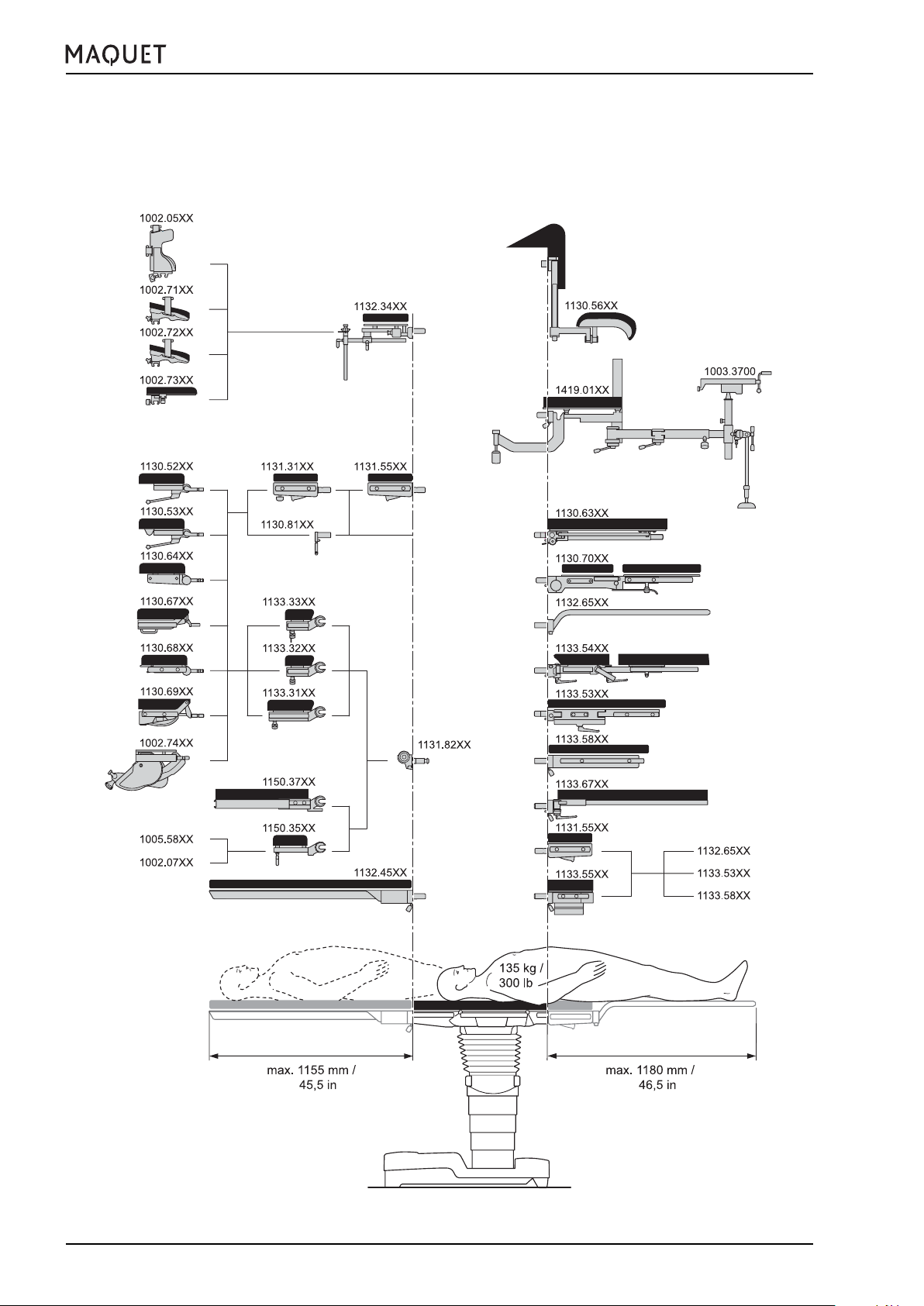
Fig. VIII-1: Accessories for patients weighing up to 450 kg (1000 lb).
For further approved accessories, please refer to the accessories list in chapter VIII.
48
GA113312EN02
Page 49

1133.12B1/B3/F1/F3
VIII. List of accessories
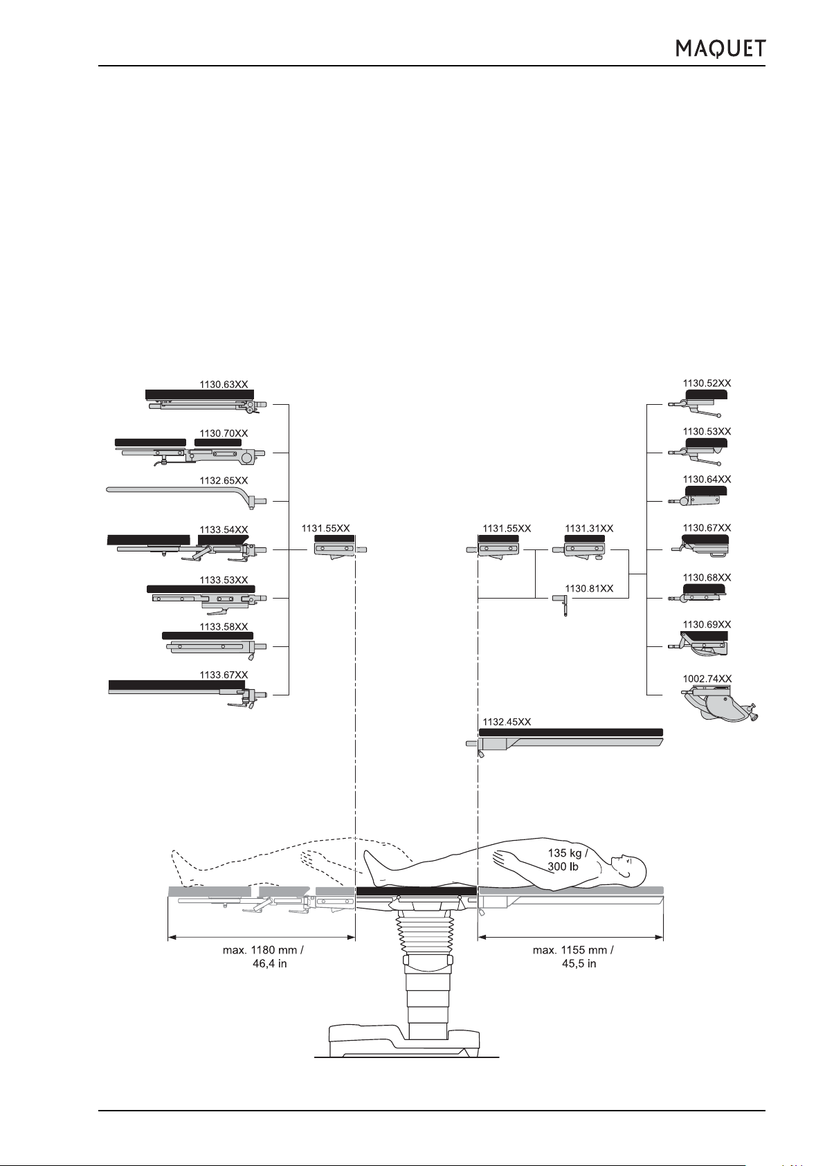
Fig. VIII-2: Accessories for patients weighing up to 225 kg (500 lb).
For further approved accessories, please refer to the accessories list in chapter VIII.
GA113312EN02
49
Page 50

VIII. List of accessories
1133.12B1/B3/F1/F3
Fig. VIII-3: Accessories for patients weighing up to 135 kg (300 lb).
For further approved accessories, please refer to the accessories list in chapter VIII.
50
GA113312EN02
Page 51

1133.12B1/B3/F1/F3
1. Accessories for head-side mounting point:
1.1 For patients weighing up to 450 kg (1000 lb)
1130.67X0 Head plate with gas strut assisted adjustment, washable
1.2 For patients weighing up to 225 kg (500 lb)
1130.52X0 Head plate, simple version
1130.53X0 Head plate with double articulation
1130.54B0 Connection bracket
1002.07A0 Head plate adapter
1002.71A0 Horseshoe-shaped head rest
1002.73A0 Head plate, flat
1002.6200 Head plate, flat
1002.72A0 Horseshoe-shaped head rest, split
1003.4700 Head support plate
1002.65A0 Connection fixture
1002.71A0 Horseshoe-shaped head rest
1002.73A0 Head plate, flat
1002.6200 Head plate, flat
1002.72A0 Horseshoe-shaped head rest, split
1003.4700 Head support plate
1005.3600 Special clamp for skull clamp
1005.5800 Supporting arm
1002.5800 Adapter
1130.64X0 Head plate
1130.67X0 Head plate with gas strut assisted adjustment, washable
1130.68B0 Head plate, long, folding down with gas strut, SFC padding, with side rails, Europe
1130.69X0 Head plate with double articulation
1002.74A0 Motor-powered head plate
1002.71A0 Horseshoe-shaped head rest
1002.73A0 Head plate, flat
1002.6200 Head plate, flat
1002.72A0 Horseshoe-shaped head rest, split
1004.75A0 Wrist support
1003.4700 Head support plate
VIII. List of accessories
1004.75A0 Wrist support
1004.75A0 Wrist support
1000.5700 Head ring, PUR
1000.5900 Gel head ring
1005.3500 Skull clamp
1002.71A0 Horseshoe-shaped head rest
1002.73A0 Head plate, flat
1002.72A0 Horseshoe-shaped head rest, split
1004.75A0 Wrist support
1.3 For patients weighing up to 135 kg (300 lb)
1150.71X0 Head plate
approved only in conjunction with the 1150.37X0 carbon-fibre back plate for neurosurgery
1130.54B0 Connection bracket
1005.2900 Basic unit
1005.25A0 Adapter
1002.71A0 Horseshoe-shaped head rest
1002.73A0 Head plate, flat
1002.72A0 Horseshoe-shaped head rest, split
1004.75A0 Wrist support
1005.3400 Clamp adapter for skull clamp
1005.3500 Skull clamp
In addition, the accessories listed under 1.2 are approved.
GA113312EN02
51
Page 52

VIII. List of accessories
2. Accessories for the back plate mounting point
2.1 For patients weighing up to 450 kg (1000 lb)
1131.82A0 Joint adapter
1150.36A0 Head plate adapter
1131.31B0 Extension segment
1131.31F0 Extension segment
1130.81A0 Head plate adapter
2.2 For patients weighing up to 225 kg (500 lb)
1131.82A0 Joint adapter
1133.31B0 Back plate for general surgery, SFC pad, Europe
1133.32B0 Short back plate for general surgery, SFC pad, Europe
1133.33B0 Back plate for neurosurgery, SFC pad, Europe
1150.34B0 Back plate for shoulder operations, SFC pad
1150.35B0 Back plate for ophthalmology, SFC pad
1150.36A0 Head plate adapter
1131.31B0 Extension segment
1131.31F0 Extension segment
1130.81A0 Head plate adapter
2.3 For patients weighing up to 135 kg (300 lb)
1150.37A0 Carbon-fibre back plate
1132.45A0 Carbon-fibre board
In addition, the accessories listed under 2.2 are approved.
1133.12B1/B3/F1/F3
3. Accessories for leg plate mounting point
3.1 For patients weighing up to 450 kg (1000 lb)
1133.53BC Leg plates, abductable, encoded, SFC pads
1133.58BC Single-section leg plate, encoded, SFC pad
3.2 For patients weighing up to 225 kg (500 lb)
1133.53BC Leg plates, abductable, encoded, SFC pads
1133.54BC Leg plate, manually adjustable via 2 joints, encoded, SFC pad
1133.58BC Single-section leg plate, encoded, SFC pad
1133.67BC Carbon-fibre leg plate, abductable, encoded, SFC pad
3.3 For patients weighing up to 135 kg (300 lb)
1130.56D0 Rectal positioning device
1003.3300 Knee supports, for fixation on side rails using clamps
1130.63X0 Leg plate with dual-joint abduction, with SFC pad
1130.65X0 Transfer board
1130.50A0 Leg plates, four-section
1130.70A0 Maquetmatic leg plate with SFC pad
1132.65A0 Transfer board
1133.55BC Seat plate extension, encoded, SFC pad
1133.53BC Leg plates, abductable, encoded, SFC pads
1133.58BC Single-section leg plate, encoded, SFC pad
1130.65X0 Transfer board
1132.65A0 Transfer board
1131.55B0 Seat plate extension, SFC pad
1133.53BC Leg plates, abductable, encoded, SFC pads
1133.58BC Single-section leg plate, encoded, SFC pad
1130.65X0 Transfer board
1132.65A0 Transfer board
1131.55F0 Seat plate extension, SFC pad
1133.53FC Leg plates, abductable, encoded, SFC pads
1133.58FC Single-section leg plate, encoded, SFC pad
1130.65X0 Transfer board
1132.65A0 Transfer board
1419.01HC Extension device, encoded
4831.001T Positioning device for spinal surgery
In addition, the accessories listed under 3.2 are approved.
52
GA113312EN02
Page 53

1133.12B1/B3/F1/F3
4. Accessories for side rails
1001.62A0 Hand operating table, Europe
9092.3214 Padding
1001.28C0 Wrist support
1001.44C0 Arm posturing device 300 mm
1001.44D0 Arm posturing device 450 mm
1001.45C0 Upper arm posturing plate
1001.4700 Leg restraint cuff
1001.56A0 Body strap, washable
1001.6000 Arm board, with ball joint adjustment
1001.85B0 Foot plate
1001.92C0 Axilla support, washable
1002.09C0 Shoulder support
1002.19C0 Fixture for body supports
1002.11A0 Back-buttocks support
1002.11B0 Pubis-sacrum-sternum support
1002.11C0 Lateral support
1002.11D0 Supporting roll
1002.21C0 Lateral support
1002.24C0 Wristlet
1003.22C0 Standard clamp
1002.57A0 Anaesthesia screen, angular
1001.4600 Arm restraint cuff
1002.59A0 Elongation tubes for anaesthesia screen, pivot-mounted
1005.86A0 Leg holders
1003.23C0 Radial setting clamp or
1003.61A0 Radial setting clamp
1002.2000 Thigh holder
1002.2300 Leg holders
1002.57A0 Anaesthesia screen, angular
1001.4600 Arm restraint cuff
1002.59A0 Elongation tubes for anaesthesia screen, pivot-mounted
1003.1000 Iliac support
1004.2400 Arm supports
1005.2300 Cross-bar attachment
1005.2900 Basic unit
1005.8700 Leg holders
1001.65A0 Goepel knee crutch
1009.02C0 Meniscus positioning device, radiotranslucent
1003.32C0 Mayo instrument table
1003.3300 Knee supports for rectal position
1004.23C0 Elbow support
1004.8000 Countertraction post for humerus
1004.91A0 Side rail extension
1004.84A0 Knee positioning device, motor-powered
1004.84B0 Knee positioning device, manual
1004.9800 Humerus positioning device
1001.4800 Weinberger hand traction device
1009.01C0 Infusion stand
VIII. List of accessories
1005.3400 Clamp adapter
1005.3500 Skull clamp
1005.3200 Skull pins for adolescents
GA113312EN02
53
Page 54

VIII. List of accessories
5. Special-purpose accessories
1000.5600 Pad
1000.5700 Head ring, PU foam
1000.5900 Gel head ring
1000.6800 Pad, segmented (for percutaneous kidney operations, spinal column)
1003.7400 PU pad for kidney operations
6. Control units
1009.81D0 Foot switch with the following functions: height, Trendelenburg/rev. Trendelenburg, back plate
1009.81D1 Foot switch with the following functions: height, Trendelenburg/rev. Trendelenburg, lateral tilt
1009.81D2 Foot switch with the following functions: height, Trendelenburg/rev. Trendelenburg, leg plates
1009.81D3 Foot switch with the following functions: height, Trendelenburg/rev. Trendelenburg, longitudinal
shift
1133.90A0 Corded hand control
1133.91A0 IR remote control
3 110 26A9 Charging station UK (230 V)
3 110 26B9 Charging unit with cable
3 110 26C9 Charging station Europe
3 110 26D9 Charging units US and Japan
3 110 26E9 Charging unit Europe, US and Japan
1133.12B1/B3/F1/F3
1150.95X0 Wall control panel
54
GA113312EN02
Page 55

1133.12B1/B3/F1/F3
IX. Spare parts list
IX. Spare parts list
You can order spare parts using the numbers listed below. Further information will be found in the spare parts lists.
1. Operating table
Head plate pad 1130.53B0 9093.0104
Pad for upper back plate 1133.31B0 9093.2424
Pad for lower back plate and seat plate 1133.12BX 9093.2383
Pad for extension segment 1131.31B0 9093.0693
Leg plate pad 1133.53BC (always 2 units required) 9093.0204
Mains cable
for 1133.12 BX (230V) 3113.3659
for 1133.12 BX (110V) 3113.3669
Rechargeable batteries (always 2 units required) 0227.0154
2. Accessories
• Hand control with spiral cable 1133.90A0
• IR remote control
IR remote control with charging station 1133.91A0
System digits and letters 9801.6234
Cover (for transfer board 1132.65A0) 9082.1223
Control cable with two plugs for foot switch 1009.81DX 0200.4273
Use only spare parts approved by MAQUET.
GA113312EN02
55
Page 56

All notes and technical data in these operating instructions reflect the status at the publication date. Since we
constantly strive to improve all MAQUET products, however, we reserve the right to adopt modifications at any
time, without prior notice. There might therefore be minor differences between the illustrations in these operating
instructions and the product’s current design. This will, however, not impar the validity and correctness of these
operating instructions as far as instructions and operational sequences herein are concerned.
MAQUET GmbH & Co. KG
Kehler Straße 31
76437 Rastatt / Germany
Phone: +49 (7222) 9 32-0
Fax: +49 (7222) 9 32-838
Service hotline: +49 (7222) 9 32-745
e-mail: info.sales@MAQUET.de
Internet: http://www.maquet.com
GA113312EN02 07 / 2005
 Loading...