

Page 1
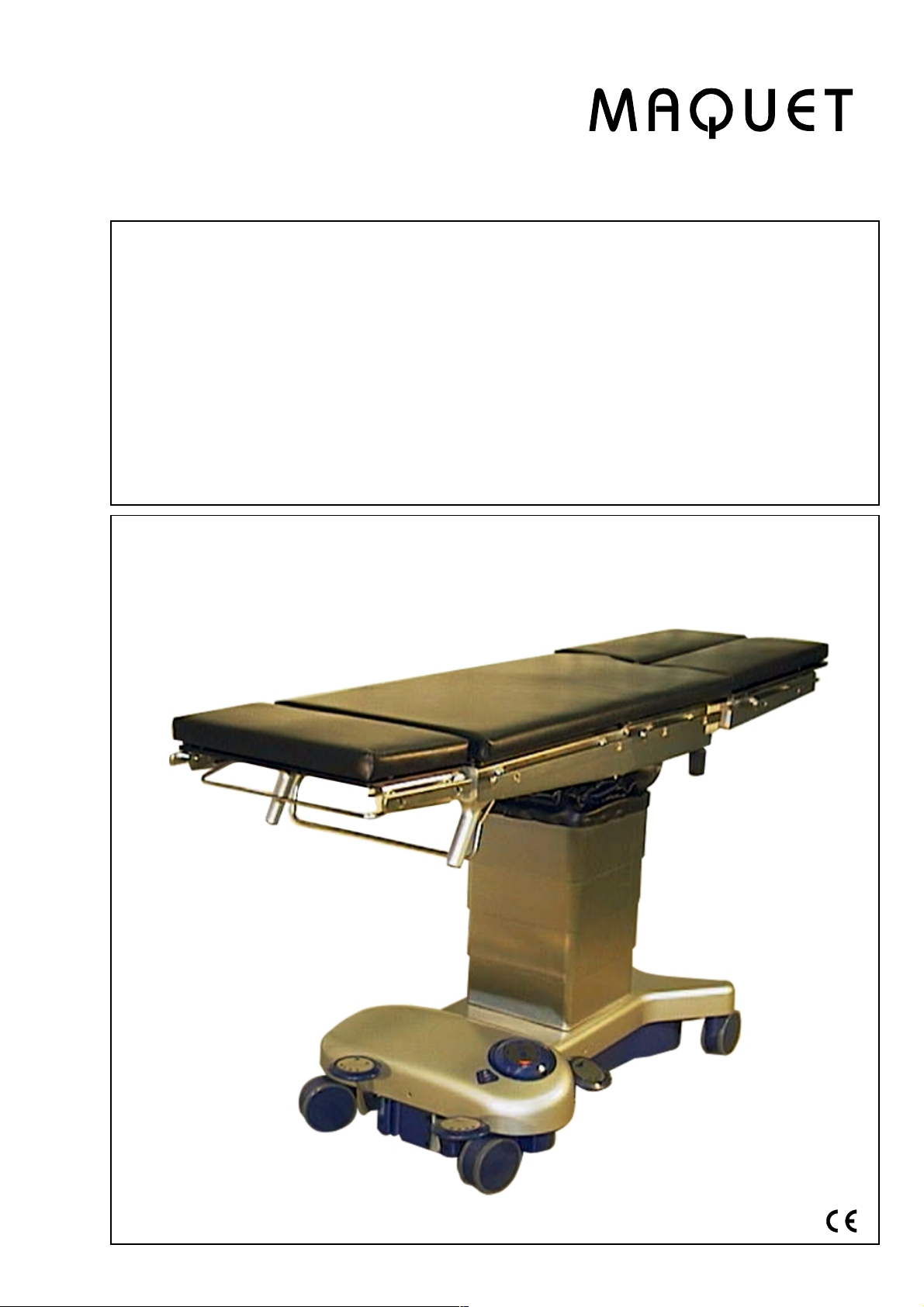
Alphaclassic
1118.02
A0/B0/E0/G0/J0/K0
Operating Instructions
Mobile Operating Table
for general surgery
Englisch
GA111802GB09
Page 2
1118.02
14
12
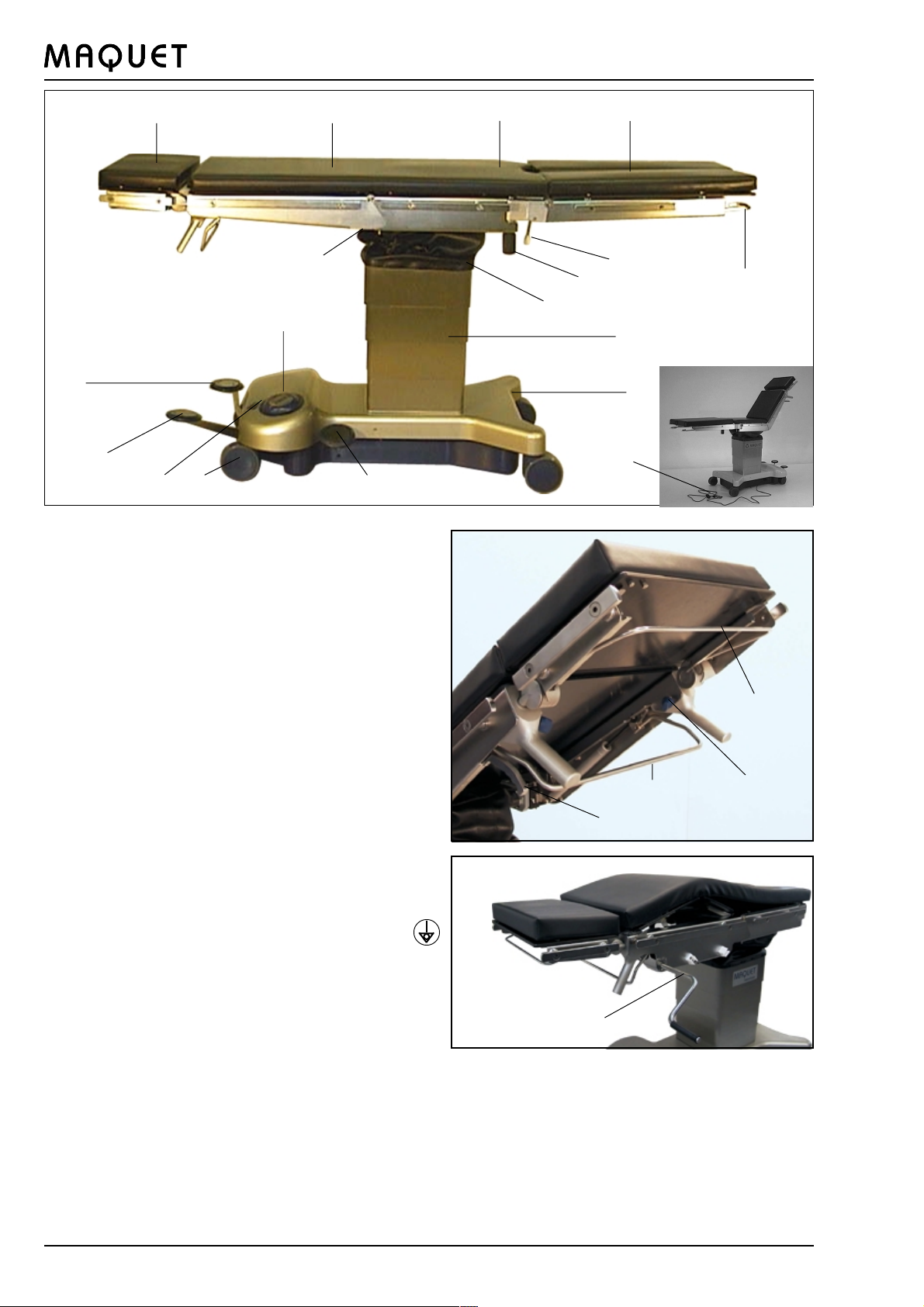
Overview
12
19
16
821
15
34
6
7
5
9
10
11
13
1 Head rest 1130.64C0/D0
2 Back plate
3 Seat plate
4 Leg plates 1118.50A0/B0
5 Lever (leg plate up/down)
6 Locking lever (leg plate)
7 Grip screw (abduct leg plates)
8 Castors
9 Bellows
10 Column casing
11 Base cover
12 Pump pedal
13 Mains power cord
14 Locking pedal (table locking)
15 Lowering pedal (lower table top)
16 Foot selector
17 Locking screw (head rest)
18 Operating bar (back plate)
19 Connecting pin for equipotential bonding
(located below table top)
20 Operating lever for head rest
21 Display: Mains supply
Battery charge level
Pump function ON
22 Release handle for longitudinal shift
23
22
18
20
17
23 Hand crank for body elevator
2
GA111802GB09
Page 3

1118.02
List of contents
Overview ................................................................................................................ 2
I. Important safety instructions ................................................................................ 4
II. Important information ........................................................................................... 6
1. Important information on the Directions for Use .............................................. 6
2. Use in the manner intended ........................................................................... 6
3. Purpose ......................................................................................................... 6
4. Basic safety aspects ..................................................................................... 6
III. General description............................................................................................... 7
1. General description ........................................................................................ 7
2. Moving/locking the operating table ................................................................. 7
3. Activating the functions .................................................................................. 8
3.1 Functions ............................................................................................ 8
3.2 Function of foot selector....................................................................... 8
3.3 Release pedal function......................................................................... 9
3.4 Lowering pedal function........................................................................ 9
3.5 Locking pedal function ......................................................................... 9
3.6 Table top functions............................................................................. 10
3.7. Body elevator (Version G) .................................................................. 11
3.8. Longitudinal shift (Versions J and K).................................................11
3.9 Light signals ...................................................................................... 11
3.10 Battery charging ................................................................................ 11
IV. Operating the operating table............................................................................ 12
1. Equipotential bonding................................................................................... 12
1.2 Operating table adjustments .................................................................. 12
2. Mains operation ........................................................................................... 12
3. Battery-powered operation ........................................................................... 12
4. Explosion protection regulations .................................................................. 12
5. Table top components .................................................................................. 13
5.3 Leg plates 1118.50X0 ......................................................................... 13
5.4 Table top padding ............................................................................... 14
5.5 Back plate adjustment ....................................................................... 14
V. Positionings ......................................................................................................... 15
1. General ........................................................................................................ 15
2. Lithotomy position ....................................................................................... 15
3. Thyroid ......................................................................................................... 16
4. Maxillo-facial surgery ................................................................................... 16
5. Lateral positioning........................................................................................ 17
6. Neurosurgical procedures............................................................................. 17
7. Orthopedic extension ................................................................................... 18
8. Gall bladder ................................................................................................. 18
VI. Maintenance and servicing ................................................................................ 19
1. Cleaning ...................................................................................................... 19
2. Disinfection .................................................................................................. 19
3. Disinfecting the castors ............................................................................... 19
4. Maintenance ................................................................................................ 20
5. Malfunctions ................................................................................................ 20
6. Nature and scope of maintenance work ........................................................ 20
7. Environmental protection .............................................................................. 20
VII. Specifications ...................................................................................................... 21
VIII. List of accessories ............................................................................................... 22
IX. Replacement parts list ........................................................................................ 23
GA111802GB09
3
Page 4
I. Important safety instructions
The operating table is designed for a patient weight limit of 135 kg (300 lb), surgical interventions may only be
performed using defined patient positions.
Make sure that the patient lies in the specified position. Never place the patients torso on the leg plates.
Danger of operating table tipping over.
Do not move an operating table with an add-on extension or rectal unit attached when a patient is lying on the
table. Danger of operating table tipping over.
Make sure that the operating table is positioned horizontally and is stable.
Secure the operating table before use.
Secure the operating table in position before transferring the patient.
Secure the patient before re-adjusting the operating table
1118.02
The table top may not be shifted longitudinally when the extension plate or the rectal positioning unit is
mounted. Hazard of collision!
Actuating the longitudinal shift feature is only permissible when the table top is in the 0-position.
When using high-frequency equipment, defibrillators and defibrillator monitors, avoid contact between the patient and metal parts of the operating table, the table tops and accessories, and do not position patients on wet
or damp surfaces or electrically conductive pads.
This may result in the patient sustaining burns.
It is absolutely essential to comply with the manufacturers Directions for Use.
Make sure that table top accessories are fixed properly.
When adjusting the operating table, take care to avoid collisions between accessories and the operating table.
Do not use worn or damaged accessories.
This may result in injury to the patient.
Non-original accessories which affect the longitudinal geometry of the table top may only be used after consultation with MAQUET.
There is no explosion protection during the battery charging cycle or when operating the table top system
powered from the mains.
Avoid endangering the patients respiratory system, nerve pathways and circulatory system by ensuring the
patients proper positioning and observing the patients condition.
Check the electrical conductivity of the operating table once a year. This check should be performed by trained
servicing personnel only.
Unplug the mains cable before opening the unit.
4
GA111802GB09
Page 5
1118.02
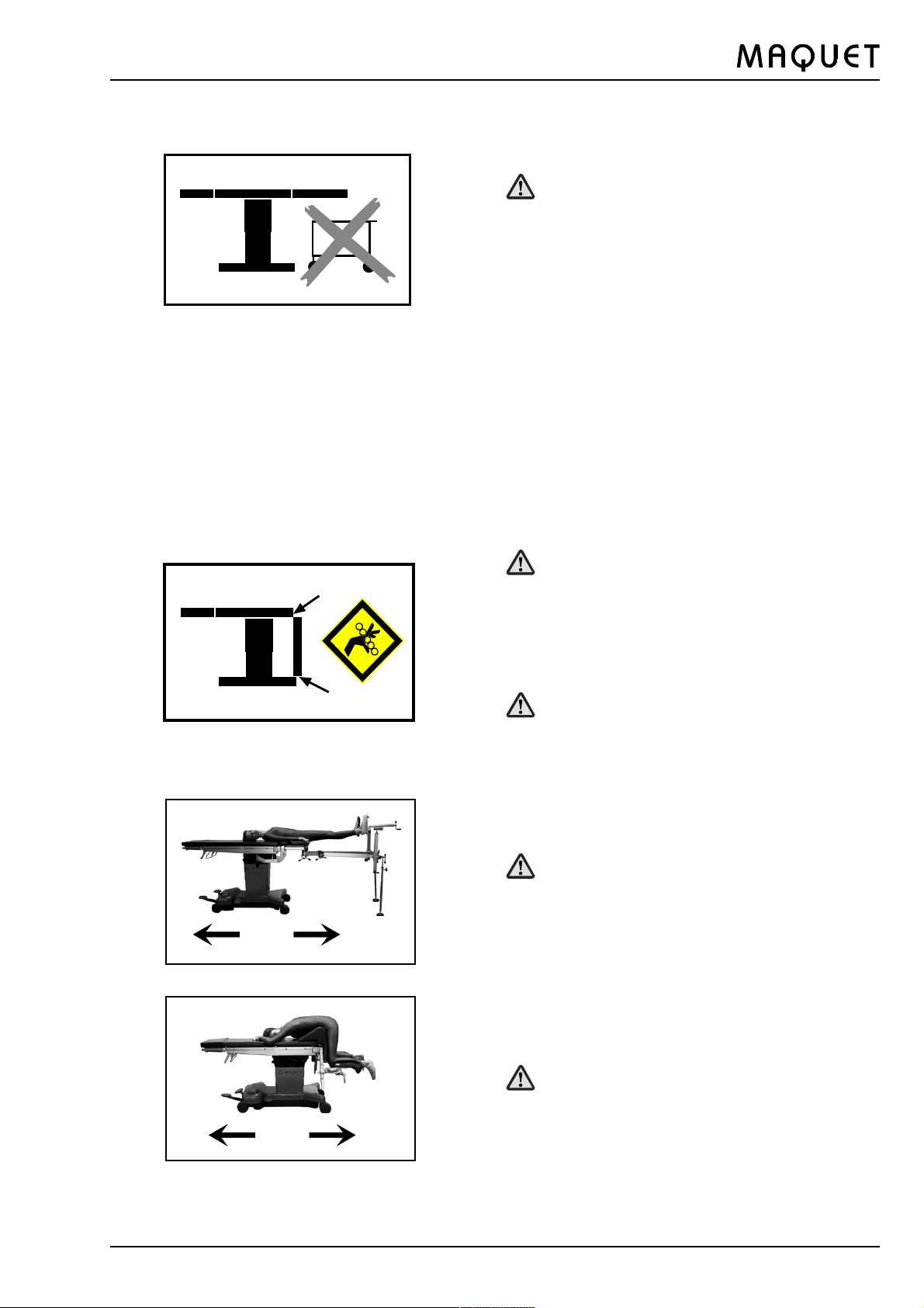
Remove possible obstacles before lowering or tilting the operating table.
Danger of operating table tipping over.
NO
Do not reach below the table top or between the
components of the table top when making adjustments.
Pinching hazard
When adjusting the table top (e.g. Trendelenburg/
reverse Trendelenburg position, height down, leg
plate down), avoid collisions between table top
components and the operating table base!
Do not move an operating table with an add-on
extension attached when a patient is lying on the
table.
Danger of operating table tipping over.
GA111802GB09
NO
Do not move an operating table with an rectal unit
attached when a patient is lying on the table.
Danger of operating table tipping over.
5
Page 6

1118.02
II.Important information
First of all, we should like to thank your clinic for choosing our mobile operating table 1118.
1. Important information on these Directions for Use:
Please read these Directions for Use carefully. We have prepared them for you so that you can familiarize yourself
with the systems characteristics.
Always follow the instructions contained here.
Keep these Directions for Use near by the equipment at all times.
In these Directions for Use, we have used the following symbols:
è Note
This symbol is displayed with all notes which help you to avoid equipment malfunctions.
This symbol indicates safety instructions in accordance with the prevailing international
standard for medical equipment.
2. Use of an operating table in the manner intended
The operating tables which MAQUET sells are intended for human medicine purposes only. Prior to use, the user
must be given instructions for operation of the equipment in the manner intended. The provision of instruction must be
verified in the form of a hand-over report. The chosen place of use for the equipment must conform to the applicable
standards and guidelines. A compulsory requirement for use is proper installation and maintenance of the equipment.
3. Purpose:
The purpose of the operating table is to position patients for surgery
directly before, during and after the operative phase
in rooms which are used for medical purposes and fulfil the following conditions:
- they are equipped with electric shock protection devices
- additional equipotential bonding
- electrically conductive floor covering (as per Groups 1 or 2 according to VDE 0107)
under medical surveillance
Due to the design of the table top, the operating table is suitable for all surgical disciplines. The range of possible
positionings is listed in the Directions for Use.
Movements are initiated manually; they are executed electrohydraulically by means of pedals and handles, otherwise
they are executed hydraulically. Side rails are provided for securing accessories in accordance with the manufacturers specifications.
The translucent table top of the operating table permits intraoperative use of X-ray equipment.
4. Basic safety aspects
CLASSIFIED BY UNDERWRITERS LABORATORIES INC: WITH RESPECT TO ELECTRIC SHOCK; FIRE
AND MECHANICAL HAZARDS ONLY IN ACCORDANCE WITH UL 2601-1
This operating table meets the provisions of the international IEC 601-1 standard and IEC 60601-2-46.
The operating table is classified as Class I equipment under the Medical Device Directive. You should include it in
your inventory.
For your maintenance work, please remember that the MAQUET Customer Service is the right address as far as
quality of work and warranty are concerned. We are sure you will appreciate that MAQUET can only accept responsibility for the safety of your equipment if installation, extension work, adjustments, modifications and repairs to your
equipment have been carried out exclusively by our Customer Service or by technical experts authorised by us and
also if the equipment has been operated strictly in accordance with our Directions for Use.
6
GA111802GB09
Page 7
1118.02
III.General description
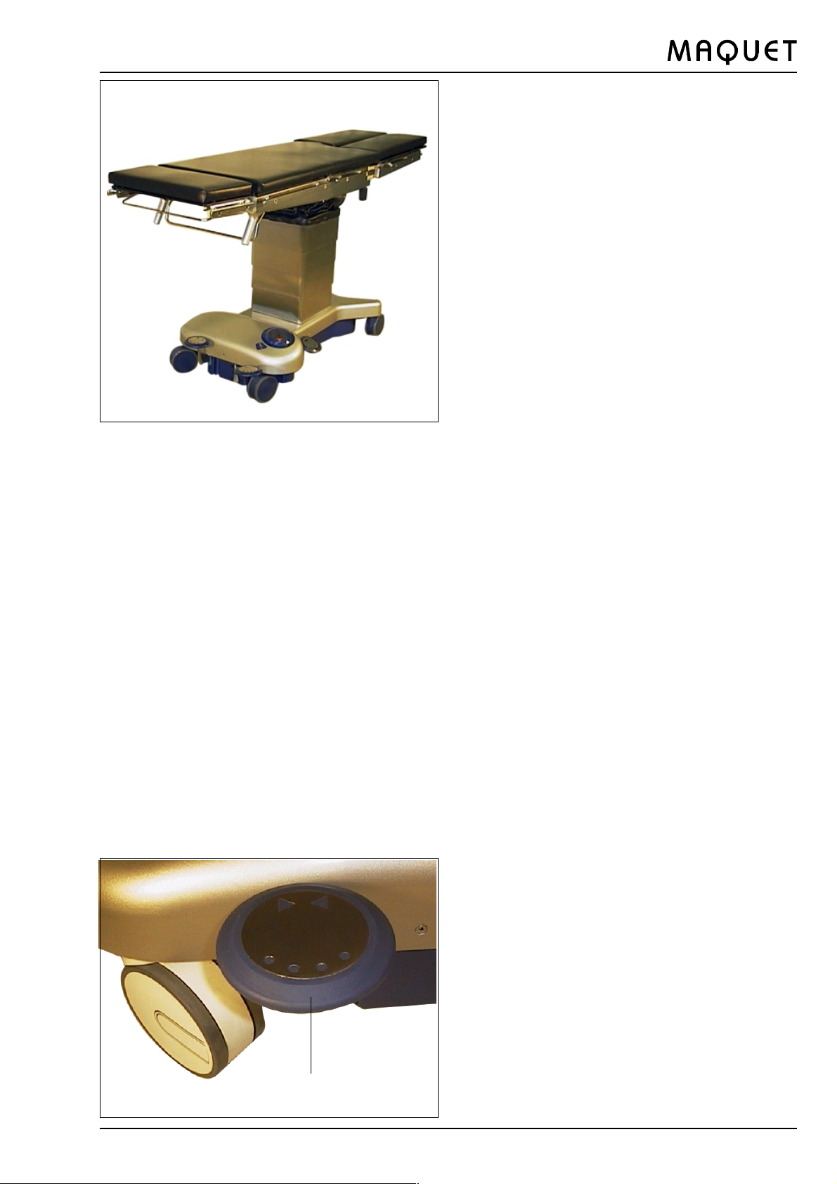
1.General description
The 1118.02 is a mobile operating table for general sur-
gery.
Depending on the leg plate type selected, the operating
table top can have up to 5 subdivisions: Located beneath
the table top are guide rails for inserting X-ray cassettes
at the head end.
X-ray cassettes can be inserted below the table top in
the head, back and seat areas.
The lateral side rails are for fixing accessories to the operating table.
Versions of the operating table:
1118.02A0 Operating table with PUR pads,
European side rails
1118.02B0 Operating table with Kaliko pads,
European side rails
1118.02E0 Operating table with Kaliko pads,
U.S. side rails
1118.02G0 Operating table with SFC padding,
European side rails and body elevator
1118.02J0 Operating table with PUR padding,
European side rails, longitudinal shift
1118.02K0 Operating table with SFC padding,
European side rails, longitudinal shift
The operating table can be enabled by releasing or fixing
a foot lever.
è The operating table is designed to handle safety pa-
tients weighing up to 135 kg as per IEC 601-1 standard. The operating table may only be equipped with
original MAQUET accessories (observe the Operating Instructions). Non-original accessories may only
be used with the manufacturers express prior approval and must be examined carefully prior to use to
make absolutely sure that they do not represent a
hazard to patients or personnel and cannot damage
the operating table.
è Note:
On the immobilised operating table, all surgical procedures may be performed on patients weighing up
to 135 kg (300 lb.).
2.Moving/locking the operating table:
è Before starting patient positioning and during the op-
eration, the operating table must always be immobilised by operating the locking pedal (14).
GA111802GB09
To move the operating table in a longitudinal direction,
l move the locking pedal (14) up.
To immobilise the operating table,
l move the locking pedal (14) down.
14
7
Page 8
12
16
1118.02
3.Activating the functions
3.1.Functions
The hydraulic functions of the operating table:
l height function
l inclination function
l lateral tilt function
are foot-activated via the followingoperating elements.
q Foot selector (16)
q Pump pedal (12)
q Lowering pedal (15)
15
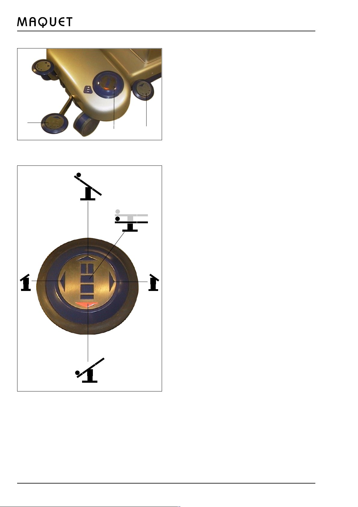
3.2 Functions of foot selector
The desired function is activated by pressing the selector
as shown.
c
a
e
d
a Table top up
b Trendelenburg position
c Reverse Trendelenburg position
d Lateral tilt right
e Lateral tilt left
a) Pressing foot selector in the middle
= height function
b) Tilting the foot selector in the
direction of the t arrow
= Trendelenburg position
c) Tilting the foot selector in the
direction of the s arrow
= reverse Trendelenburg position
d) Tilting the foot selector in the
direction of the arrow = lateral tilt right
e) Tilting the foot selector in the
direction of the arrow = lateral tilt left
t
t
b
8
GA111802GB09
Page 9

1118.02
3.3 Pump pedal
The function set at the foot selector (16) is released by
actuating the Pump pedal (12): press the pump pedal
(12) down as far as it will go. Let go of the pump pedal
(12) to stop the function. The yellow LED next to the ON
symbol lights up during the adjustment procedure
12
è Note
If the LED still lights up after completion of the adjustment procedure, please contact the MAQUET
Customer Service. For safety reasons, do not use
the table any further.
3.4 Lowering pedal function
The sole purpose of the lowering pedal (15) is to reduce
the height of the table top.
The position of the foot selector has no relevance to this
function.
15
3.5 Locking pedal function
14
When the locking pedal (14) is pressed, the two swivel
castors are locked.
Operations and patient positioning shall only be performed
when the operating table is locked.
GA111802GB09
9
Page 10

20
22
17
18
1118.02
3.6 Table top functions
The manual functions are activated via the controls on
the table top.
Operating bar for back plate (18).
Operating lever for head rest (20)
5
6
7
Locking screw for head rest (17)
Lever for leg plate (5)
Locking lever for leg plate (6)
Grip screw (abduct leg plate) (7)
Release handle for longitudinal shift (22)
Hand crank for body elevator (23)
23
5
Remove any possible obstacles before lowering or
tilting the operating table.
Danger of operating table tipping over.
6
7
6
Do not reach below the table top or between the
components of the table top when making adjustments.
Pinching hazard.
If table tops are adjusted downwards, avoid collisions with the base of the operating table when
making adjustments.
10
7
GA111802GB09
Page 11

1118.02
3.7 Body elevator (Version G)
The hand crank (23) and its mount (23a) used to actuate
the body elevator are located at the back section of the
table top. In the top position the two hard paper plates of
the back section are set to the body elevator position.
The hand crank should always be engaged in the
clips when not in use.
23a
23
Be careful when inserting the hand crank in the
mount at the back plate supporting bar or engaging it in the clips, in order to prevent injury caused
by the crank.
Ensure that the patients nerve pathways and circulation are not compromized by the body elevator adjustment.
Do not reach between the moving parts of the body
elevator during adjustment procedures. Moreover,
ensure that the patients limbs do not come between the moving parts of the body elevator.
3.8 Longitudinal shift (Versions J and K)
The release handle (22) for the longitudinal shift is located at the head end on the table top. When pulled towards the head end, this handle releases the locking
mechanism for the longitudinal shift; the table top can be
shifted manually to the desired position. When shifting
the table top, hold it with both hands at the head end.
When the handle (22) is released, the table top is locked
automatically (9 positions, spacing 36.5 mm).
22
21
Actuating the longitudinal shift feature is only permissible when the table top is in the 0-position.
Check to ensure that the table top is properly locked
before displacing the table in the longitudinal direction or before actuating the Trendelenburg adjustment feature.
3.9 Light signals (21)
Green LED: The operating table is connected to the
mains supply via the mains cable. The batteries are being charged.
Red LED: Recharge the batteries.
Yellow LED: The adjustment is being made.
3.10 Charging the batteries
Connect the mains cable of the operating table to the
mains supply to charge the batteries. A full charge takes
about 15 hours. The electronic circuitry prevents overcharging. We recommend to recharge the batteries overnight or at the weekend.
GA111802GB09
New and old batteries shall not be combined!
Always replace the complete set of batteries
11
Page 12

1118.02
IV. Operating the operating table
1.Equipotential bonding:
Connect the equipotential bonding pin (19) and the equali-
zation wire to an equipotential bonding system in the
operating room (in accordance with VDE-0107 or the prevailing national regulations).
1.2 Operating table adjustments
Height, Trendelenburg/reverse Trendelenburg positions and
lateral tilt are set at the foot selector (16) and released
by means of the pump pedal (12) (see Chapter III, Sec-
a
tion 3). The adjustments of the individual table top sections are described in Chapter IV, Section 5.
b
2. Mains operation
Use the mains power cord (13) to connect the operating
table to the mains supply. To do so, connect the mains
power cord (about 4.5 m long) to the socket at the operating table base and the mains supply. The green LED
(a) at the operating table base 21 will light up during this
procedure.
The separation of the OR-table from the mains is
made by the power plug
è Note
Damaged mains power cords will have to be replaced!
Disconnect the operating table immediately from the
mains supply!
3. Battery powered operation
Unplug the mains power cord of the operating table. The
capacity of the fully charged batteries allows use of the
operating table for at least 6 operations. Recharge the
batteries when the red LED (b) at the table base lights
up.
12
Connect the mains power cord of the operating table to
the mains supply to charge the batteries. A full charge
takes about 15 hours. The electronic circuitry prevents
overcharging. We recommend to recharge the batteries
overnight or at the weekend.
è Note
New and old batteries shall not be combined!
Always replace the complete set of batteries.
è Note
Battery powered operation of the operating table is
generally preferable to mains operation.
If the batteries are discharged, the operating may
be adjusted manually by means of the release pedal.
GA111802GB09
Page 13

1118.02
4. Explosion protection regulations:
The blue 1118.11A0 pads are not electrically conductive.
These pads must not be employed when using inflammable detergents and disinfectants there is no explosion
protection!
You can find details of the classification of areas subject
to explosion hazards into zones in Information Leaflet M
639, which is issued by the Professional Association for
Health and Welfare.
5.Table top components
5.1 Head rest 1130.64A0/B0/C0
To fix the head rest (1), insert the two pins into the locating holes until they fully engage. Then tighten the two
locking screws (17).
17
Check to see if the head rest is attached securely
by pulling it.
5.2 Adjusting the head rest
The head rest can be inclined downwards by pulling the
end of the plate up. The head rest engages automatically
step by step.
To incline the head rest upwards, pull the operating bar(20)
towards the padding. The head rest is automatically located in the next ratchet after you release the operating
lever (20).
è Make sure you comply with the Directions for Use for
the head rest.
5.3 Leg plates 1118.50X0
To attach the leg plate 1118.50X0, insert the pin into
the locating hole up to the stop. Pull the locking lever
(6) towards the foot end up to the stop. Insert the pin
fully into the locating hole, with the locking lever still
pulled. Release the locking lever so that it returns to
its original position.
The leg plate can be folded down and into the horizon-
5
6
7
tal position by pressing down lever (5) at the foot end
of the operating table.
The leg plates can be abducted by slackening the grip
screw (7). To secure the leg plate in a detent position,
re-tighten the grip screw (7).
To remove the leg plate, pull the locking lever (6) to-
wards the foot end of the operating table and pull the
leg plate out from the locating holes.
GA111802GB09
13
Page 14

18
1118.02
5.4 Table top covering
The SFC table top padding is affixed to the paper base
laminate plates by Velcro fasteners.
The PUR pads are also attached to the frame by means
of bolts.
5.5 Back plate adjustment:
The table top is equipped with a manually adjustable back
section with gas-filled spring support and is activated by
means of the bar (18).
When a patient of normal weight is lying on the table top,
the motion of the back plate is normally compensated.
When the back plate is not bearing any load, it moves up
after you release the bar.
The back plate is automatically immobilised after you
release the bar.
14
GA111802GB09
Page 15

1118.02
V. Positionings
1. General
The operating table must be integrated in the
equipotential bonding system of the operating room.
For this purpose, connect the equipotential bonding pin
and the equalisation wire to an equipotential bonding of the operating room near the patient. An equalisation cable (5 m long) with connectors at either end is
supplied with the operating table.
After positioning the patient, check to see if all the
excentric levers are closed and if all clamping screws
on the operating table as well as the accessories are
fastened tightly.
è Note
According to generally recognized hygiene regulations, the table top must be draped prior to use.
HF surgery
Use of defibrillators and defibrillator monitors
When using HF equipment, defibrillators and
defibrillator monitors, it is imperative that you
observe the equipment manufacturers Directions for Use, since ignoring the prescribed
safety precautions can result in serious damage to equipment or personal injury. Contact
between the patient and metal parts of the
operating table or operating table accessories
can cause burns. There is also a risk of burning if the patient is placed on damp or wet
surfaces or drapes on the electrically conductive padding of the operating table.
2. Lithotomy position
Immobilize the operating table.
Attach the leg supports to the side rails near the leg
plate mounts using the radial setting clamp.
Position the patients legs and remove the leg plates.
Move the back plate upwards with the bar (18).
Tilt the table top slightly into the Trendelenburg posi-
tion; set the dome-shaped selector switch (16) to b.
Adjust the inclination by pressing pedal (12).
Move the leg supports into position.
Recommended equipment
1001.65A0 Goepel knee crutch (2 pcs.)
1003.23C0 Radial setting clamp (3 pcs.)
1002.57A0 Anaesthesia screen
1002.59A0 Elongation tubes for anaesthesia screen
1001.44D0 Arm posturing device
1002.24C0 Wristlet
Alternative:
1002.2300 Leg holder with straps
GA111802GB09
15
Page 16

1118.02
3. Thyroid
Immobilise the operating table
Tilt the table top into the Trendelenburg position
Move the back plate upwards
Align the leg plate
Adapt the head rest
Recommended equipment
1132.64X0 Head rest
1002.57A0 Anaesthesia screen
1003.23C0 Radial setting clamp
1001.44D0 Arm posturing device
1002.24C0 Wristlet
1001.56A0 Body strap
1002.59A0 Elongation tubes for anaesthesia
screen
è Note:
Be sure to comply with the Directions for Use for all
accessories used.
4.Maxillo-facial surgery
Immobilize the operating table
Attach the required head positioning accessories to
the table top using the connecting bracket 1130.54B0
Tilt the table top into the Trendelenburg position
Move the back plate upwards
Align the leg plate
Adapt the head positioning accessories
Recommended equipment
1130.54B0 Connecting bracket
1002.64A0 Connecting fixture
1002.7000 Horseshoe-shaped head rest, split
1002.57A0 Anaesthesia screen
1003.23C0 Radial setting clamp
1001.44D0 Arm posturing device
1002.24C0 Wristlet
1002.59A0 Elongation tubes for anaesthesia
screen
è Note:
Be sure to comply with the Directions for Use for all
accessories used.
16
GA111802GB09
Page 17

1118.02
5. Lateral positioning (e.g. kidney, thorax)
Immobilize the operating table
Tilt the table top into the reverse Trendelenburg posi-
tion
Move the back plate downwards
Adapt the head rest
Recommended equipment
1130.53B0 Double articulation head rest
1002.57A0 Anaesthesia screen
1003.23C0 Radial setting clamp
1001.44D0 Arm posturing device
1001.56A0 Body strap
1001.4600 Arm restraint cuff
1002.21C0 Lateral support
1002.19C0 Fixture for body supports
1002.11A0 Back-buttocks support
1002.59A0 Elongation tubes for anaesthesia screen
è Note:
Be sure to comply with the Directions for Use for all
accessories used.
6. Neurosurgical procedures (patient in prone or
supine position)
Immobilize the operating table
Now attach the neurosurgical head positioning acces-
sories using the connecting bracket 1130.54B0
Lay the patient in the prone or supine position
Set the head positioning accessories
Recommended equipment
1130.54B0 Connecting bracket
1005.2900 Basic unit
1005.3400 Clamp adapter
1005.3500 Mayfield skull clamp
1002.57A0 Anaesthesia screen
1003.23C0 Radial setting clamp
1101.44D0 Arm posturing device
1002.59A0 Elongation tubes for anaesthesia screen
è Note:
Be sure to comply with the Directions for Use for all
accessories used.
GA111802GB09
17
Page 18

1118.02
7.Orthopedic extension
l Immobilize the operating table
l Attach extension unit 1419 and secure the
supports
l Remove the head rest
l Place patient on table and position legs
Recommended basic equipment
1419.01X0 Extension unit
1003.23C0 Radial setting clamp (3 pcs.)
1002.57A0 Anaesthesia screen
1001.44D0 Arm posturing device
1002.59A0 Elongation tubes for anaesthesia
screen
8. Gall bladder
l Immobilize the operating table
l Tilt the table top into the reverse Trendelenburg
position
l Move the back plate downwards
l Adapt the head rest
Recommended equipment
1130.64C0 Head rest
1002.57A0 Anaesthesia screen
1003.23C0 Radial setting clamp
1001.44D0 Arm posturing device
1002.24C0 Wristlet
1001.56A0 Body strap
1002.59A0 Elongation tubes for anaesthesia
screen
18
GA111802GB09
Page 19

1118.02
VI. Maintenance and servicing
We recommend you cover the operating table with drapes
when it is not in use.
è Where the lateral tilt and Trendelenburg/reverse
Trendelenburg functions have not been used for an
extended period of time, play may occasionally develop in the universal joint suspension.
Rectification:
Move the table top to the final position in each direction, e.g. tilt to the left and right, to the Trendelenburg
and reverse Trendelenburg positions.
The hydraulic system should be serviced by MAQUET
Customer Service staff only.
1. Cleaning
Avoid excessive use of water on the surfaces of the mobile operating table.
Also avoid spraying joints with spray cleaning or disinfection equipment.
Pressurized jets of water or detergent can result in liquid
entering the gaps between joints and causing corrosion.
To clean the operating table and accessories, we recommend you use a weak alkaline detergent (soap solution)
containing tensides and phosphates as active agents.
To clean the table, align the operating table horizontally
and move it to its highest position.
If surfaces are heavily soiled, use the detergent in concentrated form. Afterwards, wipe the surfaces with clean
water and remove any excess water with a dry cloth.
2. Disinfecting
To disinfect the operating table, we recommend you use
commercially available surface disinfectants on an aldehyde base in aqueous solution. Make sure you use an
agent that appears in the DGHM* list. Here, you can find
additional information on the individual constituents in the
disinfectants.
è Note:
The disinfectant should not contain the following components:
Chlorine or chlorine-splitting compounds
These agents attack the metallic surface.
Alcohol or compounds of alcohol.
Hand disinfectants contain alcohol.
These agents attack plastic parts, e.g. operating table padding, operating levers.
These agents form flammable mixtures.
* Deutsche Gesellschaft für Hygiene und Mikrobiologie DGHM
(German Society for Hygiene and Microbiology),
c/o Institut für Hygiene und Mikrobiologie
Universität Würzburg
Josef-Schneider-Str. 2
97080 Würzburg
http://www.dghm.org
GA111802GB09
3. Disinfecting the castors
Turn the castors outwards. Wipe the castors with surface disinfectants.
19
Page 20

1118.02
4. Maintenance
The operating table will have to be serviced once a year by
the MAQUET factory service department or by service technicians authorized by MAQUET to do so.
Please adhere to prescribed maintenance intervals as otherwise guarantee coverage will lapse.
In so doing you also make a contribution to patient and staff
safety and extend the useful life of your costly equipment.
We recommend concluding a maintenance contract with
MAQUET.
Outside Germany please contact your local representative in
all matters relating to service.
5. Troubleshooting
If you are having trouble with your equipment, please contact your local MAQUET representative or our factory. Please
give us detailed information regarding the symptoms of the
trouble and state the serial number of the equipment. This
will enable us to remedy your problem more quickly.
6. Nature and scope of maintenance work
Inspect components and joints critical to the functioning of
your equipment for wear and corrosion.
Pay special attention to the following parts:
Connecting bolts of the table top
Fastening bolts of the column guide
Pump and pump pedal suspension
For your patients safety, you are strongly advised to comply
with the yearly maintenance intervals.
è Note:
Non-observance of the prescribed maintenance intervals
will render the warranty on the equipment null and void.
Special tools are required to perform maintenance work
on the equipment.
However, servicing and repair work should always be referred to the trained technicians of MAQUETs Customer
Service.
è Note:
Do not attempt to perform any repairs if the equipment
malfunctions, and never use force.
7.Protection of the environment
Please note the following:
Packaging materials:
The materials used for packaging MAQUET products are
environmentally friendly. They are made of untreated wood,
cardboard, recyclable plastics or other reusable materials.
MAQUET-Products:
MAQUET takes used and not recyclable Products back.
All parts will be deposited environmentally.
Please call your MAQUET-Service to get more information.
Plastic components:
Large plastic components have a symbol to indicate what
type of plastic they are made of in order to make recycling
easier. Padding can be disposed of through the hospital
waste system.
Batteries:
Batteries can be sended to the lokal recycling system.
You can also get information from your MAQUET Service.
MAQUET will take the batteries back also.
20
GA111802GB09
Page 21

1118.02
95°
100 mm
290 mm
25°
VII. Technical specification
Operating table type: 1118.02
Length without head rest: 1790 mm
Length with head rest: 2075 mm
Width of table top: 510 mm
Width across side rails: 570 mm
Height: 650 - 1000 mm
Inclination in Trendelenburg adjustment: 25°
Reverse Trendelenburg adjustment: 25°
Lateral tilt, either side: 15°
Back up: 60°
Back down: 50°
Body elevator (Version G): 100 mm
Longitudinal shift (Versions J and K): 290mm
Leg plates up: 0°
Leg plates down: 95°
Weight: approx. 186 kg
Max. weight of patient: 135 kg
For heavier loads, consult the manufacturer
+
_
15°
+ 60°
- 50°
Electrical specifications
Nominal voltage: AC 100/110-115/127
200/220/230-240VCA
Frequency: 50/60 HZ
Power consumption: max. 400 VA
Protection class: II, (Double Insulated)
Degree of protection
against electric shock: Type B
Enclosure leakage current meets requirements of
patient leakage current of IEC 601-1 for CF applied
parts.
IPX4* IPS** SELV*** DC 24V
Duty cycle: int. 10 min. on/20 min. off
Explosion-protection: AP during battery operation
Use in potentially explosive
atmospheres of types AP-M
with mains connections not
allowed.
Rechargeable batteries: 2 batteries 12V / 6,5 Ah
Typ: A512 / 6,5 S
GA111802GB09
Classification: Class I as per Medical
Device Directive
*IPX = Protection against ingress of liquids (splashproof)
**IPS = Internal power source
***SELV= Safety extra low voltage
21
Page 22

VIII. List of accessories
Non-original accessories which affect the longitudinal geometry of the table top may not be used without the
express prior approval of MAQUET.
Always read the Directions for Use prior to use of accessories.
è Note
Non-original accessories (for fixing to the side rails) must be examined carefully prior to use to make absolutely
sure that they do not represent a hazard to patients or personnel and cannot damage the operating table (e.g. as
a result of possible collisions).
In particular, heavy accessories or accessories with a long leverage (retractor systems and the like) can cause
damage and therefore require close examination.
Listed below are all the accessories that may be attached to the operating table 1118.02X0.
This list has been sub-divided as follows: 1. Accessories for attachment to the side rails
2. Accessories for attachment to the head-end interface
3. Accessories for attachment to the foot-end interface
4. Pad
5. Other accessories
6. Accessories for versions 1118.02E0 only
1118.02
1. Accessories for attachment to the slide rails
1001.44C0 Arm posturing device, 300 mm long
1001.44D0 Arm posturing device, 450 mm long
1001.56A0 Body strap, washable
1002.24C0 Wristlet
1002.19C0 Fixture for body supports
1002.11A0 Back-buttocks support
1002.11B0 Pubis-sacrum-sternum support
1002.11C0 Lateral support
1002.11D0 Support roll
1001.6000 Arm board, adjustable via ball-and-socket joint
1001.85B0 Foot plate
1002.09C0 Shoulder supports
1003.23C0 Radial setting clamp
1001.65A0 Goepel knee crutch
1003.1000 Iliac support
1005.86A0 Leg holders with lower leg stirrups and gas-damped spring adjustment
1005.8700 Pair of leg holders, with adjustable lower leg support
1002.2300 Leg holder with straps
1009.02C0 Meniscus-positioning device
1002.57A0 Anaesthesia screen, L shaped
1001.4600 Arm restraint cuff
1002.59A0 Elongation tubes for anaesthesia screen
1005.2300 Cross-bar attachment (for NEURO positioning, patient seated)
1005.2900 Basic unit Mayfield
1002.21C0 Lateral support
1003.32C0 Mayo instrument table
1003.3300 Knee supports, pair
1009.01C0 Infusion Holder washable
22
1005.3400 Clamp adapter for Mayfield skull clamp
1005.3500 Mayfield skull clamp
1005.2500 Connecting element
GA111802GB09
Page 23

1118.02
2. Accessories for head-end interface
1130.53A0 Head rest with double articulation, can be folded down, PUR
1130.53D0 Head rest, with double articulation, washable, PUR
1130.64A0/B0/C0 Head rest
1130.54B0 Connecting bracket
3. Accessories for foot-end interface:
1005.78C0 Operating table top for babies and infants
1118.50A0/B0/E0 Pair of leg plates, can be folded down and abducted
1117.01A0/C0 Pair of leg plates, can be folded down and abducted
1117.01B0/EU Pair of leg plates, can be folded down and abducted, SFC
1130.50A0 Pair of leg plates, can be folded down and abducted, PUR
1130.50D0 Pair of leg plates, can be folded down and abducted, PUR, washable
1130.55A0/B0/C0 Seat plate extension
1130.56A0 Rectal positioning device
1130.58A0/B0/C0 Transfer board, one-piece design
1130.60F0/G0 One piece folding leg plates
1132.65A0 Transfer board
1130.65A0/B0 Transfer board, one-piece design, lightweight model
1419.01C0 Extension device
4. Pad
1000.5700 Head ring, Pu
1000.6800 Pad, segmented
1003.7400 Cushion, semi-circular
5. Orther accessories
1117.45A0 Drainage bowl incl. plastic guide frame
1002.8900 Cassette slide
6. Accessories for versions 1118.02E0 only
1118.80A0 X-ray top
IX. Replacement parts list
Component parts which belong to the operating table 1118.02 or which may be used in combination with the
operating table.
Spare parts can be ordered under the specified numbers. For details of further parts and information, refer to the
replacement parts list EL111802DE01 and the accessories replacement parts lists.
1. Operating table replacement parts
SFC-pad 1000.66D0 9092.3074
Back plate pad, PUR 3112.6852
Seat plate pad, PUR 3112.2982
Rechargeable batteries (for 1118.02AE/BE, two batteries required) 0 227 009 4.
Mains cable for 1118.02AE 1004.51A0
Mains cable for 1118.02BE 1004.51B0
2. Accessories replacement parts list
Leg plate pad 1118.50A0 right 3112.4693 PUR
left 3112.4683 PUR
Leg plate pad 1118.50B0 SFC-pad 9092.0204
Head rest 1130.64C0 SFC- pad 9092.0104
1130.64D0 PUR padded 3 113.300 3.
Use only spare parts approved by MAQUET.
GA111802GB09
23
Page 24

All information and technical specifications contained in these Operating Instructions apply at the time
of going to press. In keeping with our policy of continuous product improvement, however, we reserve
the right to change specifications without prior notice.
MAQUET GmbH & Co. KG
Kehler Strasse 31
D-76437 Rastatt
Surgical Tables Division
Phone ++49 7222 932-0
Telefax ++49 7222 932-838
Service hotline ++49 7222 932-745
e-mail: info.sales@maquet.de
Internet: http://www.maquet.com
We reserve the right to make technical and design changes.
GA111802GB09 04 / 2003
 Loading...